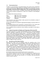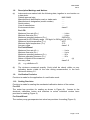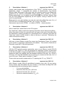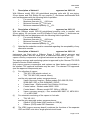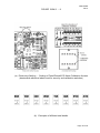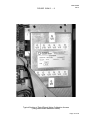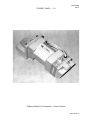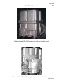
1
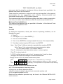
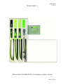
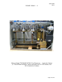
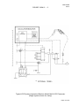
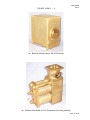
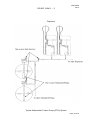
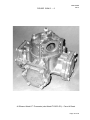
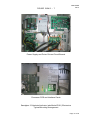
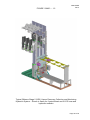
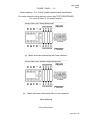
NMI 5/6M/3
Rev 2
Certificate of Approval
NMI 5/6M/3
Issued by the Chief Metrologist under Regulation 60
of the
National Measurement Regulations 1999
This is to certify that an approval for use for trade has been granted in respect of
the instruments herein described.
Gilbarco Model T923A8ND SK700-2 Fuel Dispenser for Motor Vehicles
submitted by
Gilbarco Australia Limited
20 Highgate Street
AUBURN
NSW
2144
NOTE: This Certificate relates to the suitability of the pattern of the instrument for
use for trade only in respect of its metrological characteristics. This Certificate
does not constitute or imply any guarantee of compliance by the manufacturer or
any other person with any requirements regarding safety.
This approval has been granted with reference to document NMI R 117-1,
Measuring Systems for Liquids Other than Water, dated July 2011.
This approval becomes subject to review on 1/12/20, and then every
5 years thereafter.
DOCUMENT HISTORY
Rev
0
1
2
Reason/Details
Pattern & variants 1 to 8 approved – certificate issued
Pattern & variants 1 to 8 updated & amended (software
version & Test Procedure) – certificate issued
Pattern & variants 1 to 8 reviewed & amended (density range)
– certificate issued
Date
26/11/10
13/02/13
24/08/15
Page 1 of 23
NMI 5/6M/3
Rev 2
CONDITIONS OF APPROVAL
General
Instruments purporting to comply with this approval shall be marked with approval
number ‘NMI 5/6M/3’ and only by persons authorised by the submittor.
It is the submittor’s responsibility to ensure that all instruments marked with this
approval number are constructed as described in the documentation lodged with
the National Measurement Institute (NMI) and with the relevant Certificate of
Approval and Technical Schedule. Failure to comply with this Condition may
attract penalties under Section 19B of the National Measurement Act and may
result in cancellation or withdrawal of the approval, in accordance with document
NMI P 106.
Auxiliary devices used with this instrument shall comply with the requirements of
General Supplementary Certificates No S1/0/A or No S1/0B.
Signed by a person authorised by the Chief Metrologist
to exercise their powers under Regulation 60 of the
National Measurement Regulations 1999.
Dr A Rawlinson
Page 2 of 23
NMI 5/6M/3
Rev 2
TECHNICAL SCHEDULE No 5/6M/3
1.
Description of Pattern
approved on 26/11/10
A Gilbarco model T923A8ND SK700-2 fuel dispenser (Figures 1 and 2) for motor
vehicles is approved to dispense LPG and various grades of liquid fuels, in
attendant-operated mode, or in attended self-service mode using any compatible
(#) approved control console. The meter is adjusted to be correct for the liquid for
which it is to be verified. The pattern includes Batchen model MkIII meters for
LPG and Gilbarco model C+ meters for other fuels.
(#)
‘Compatible’ is defined to mean that no additions/changes to
hardware/software are required for satisfactory operation of the complete
system.
1.1
Field of Operation
The field of operation of the measuring system is determined by the following
characteristics:
Characteristics common to all systems
•
•
Minimum measured quantity, Vmin
Ambient temperature range
2L
-25 to 55°C
Characteristics specific to LPG metering
•
•
•
•
•
•
•
Maximum flow rate, Qmax
40 L/min
Minimum flow rate, Qmin
8 L/min
Maximum pressure of the liquid, Pmax
2450 kPa
LPG density detection range (at 15°C)
500 kg/m³ to 590 kg/m³
Volume conversion to 15°C over a liquid temperature range of -5°C to 45°C
Operating pressure is maintained at least 200 kPa above the equilibrium
vapour pressure of LPG.
Accuracy class
1.0
Characteristics specific to petrol/diesel metering
•
•
•
•
•
•
•
•
Maximum flow rate, Qmax
Minimum flow rate, Qmin
Maximum pressure of the liquid, Pmax
Minimum pressure of the liquid, Pmin
Range of liquids viscosity (at 20°C)
Maximum temperature of the liquid, Tmax
Minimum temperature of the liquid, Tmin
Accuracy class
(#1)
Minimum pressure required for effective operation of the gas elimination
device.
The flowmeter is adjusted for use with one product viscosity. Fuels include
kerosene, distillate and various grades of petrol (which may include up to
10% ethanol, E10). The pattern and variants constructed for use to
dispense various grades of pure biodiesel and biodiesel/distillate blends (to
Australian government standard).
(#2)
50 L/min
5 L/min
350 kPa
140 kPa
0.5 to 20 mPa.s
50°C
-10°C
0.5
(#1)
(#2)
Page 3 of 23
NMI 5/6M/3
Rev 2
1.2
Description of the Metering Systems
The Gilbarco model T923A8ND SK700-2 dispenser (Figures 1 and 2) includes the
following components or features:
•
•
A Batchen model Mk-V constant bleed vapour elimination device.
Two Batchen model Mk VI spring-loaded pressure differential valves.
•
Two Batchen model MkIII two-piston liquefied petroleum gas (LPG)
flowmeters each fitted with a Gilbarco model 510 pulse generator for LPG.
With an optional magnetic coupling between the meter and the pulse
generator.
•
•
•
•
•
•
•
•
(*)
A Gilbarco model Sandpiper 2 (aka model E101) calculator/indicator
configured for use with a density detection device enabling the volume
conversion to 15°C for LPG.
With an optional pre-setting device.
Two Gasguard model LGI LPG or any other NMI-approved LPG nozzles (*).
Pressure inputs for petrol and diesel grades supplied by remote
submersible turbine pumps (STPs).
Six measurement transducers each comprising a Gilbarco model C+ four
piston positive displacement flowmeter fitted with an SK700-2 model
Encore 510 pulse generator.
A pre-set facility for volume or price.
Six 16 mm ZVA Elaflex or ZVA 2 Elaflex nozzle or any other NMI-approved
nozzle (*).
Note that the submittor must be consulted regarding the acceptability of any
alternative nozzles.
A compatible NMI-approved control system may also be connected to provide selfservice operation.
1.3
System Description for LPG (Figure 3)
(i)
The supply tank may be located above or below ground depending on the
type of pump used.
(ii)
The pump may be positioned above the supply tank, in which case the
pump shall be a multi-stage regenerative turbine LPG pump specially
designed for use in suction lift installations. Alternatively, the pump shall
be positioned below the supply tank or a submersible turbine pump (STP)
may be located within the supply tank so that it is always in a state of
flooded suction (suction head installations). There shall be no restrictive
fittings within ten pipe diameters of the pump inlet.
The inlet pipe to the pump is larger than the outlet pipe from the pump. The
external pump by-pass relief valve is installed in a line returning to the
vapour space of the supply tank.
A pump supplying LPG to several flowmeters shall be of sufficient capacity
rating to ensure that when all flowmeters are in use the flow rate through
each flowmeter is greater than Qmin.
Page 4 of 23
NMI 5/6M/3
Rev 2
(iii)
The LPG flowmeters are protected from the measurement of vapour by a
Batchen model Mk-V vapour eliminator (Figure 4a) and an LPG
Measurement model DSSG98 LPG or model DSSG-2000 monitoring
device.
The gas elimination device allows a continuous bleeding of LPG and any
vapour back to the vapour space of the supply tank, via a vapour return line
of not less than 20 mm in diameter.
In addition, a vapour detection sensor is incorporated which activates the
flow control valve to stop the measurement when an excessive amount of
vapour is detected.
The gas elimination device also has provision for inserting a reference
thermometer for verification of LPG temperature measurement.
(iv)
The measurement transducers are two Batchen model Mk III two piston positive
displacement LPG flowmeters (Figure 4b) each fitted with a Gilbarco model
Encore 510 dual channel pulse generator. The shaft of the meter and the
pulse generator rotate twice for a throughput of one litre. The pulse
generator incorporates gears to produce, in conjunction with the software of
the calculator/indicator, a pulse output of 250 pulses/litre. The outlet of the
meter is connected to a flow control valve with an optional pre-set valve.
The flowmeter is suitable for use over a flow rate range of 8 to 50 L/min, but
the dispenser is only approved for use up to a maximum of 40 L/min.
(vii)
The transfer device is a Gasguard model LGl LPG nozzle, or any other
compatible NMI-approved LPG nozzle (*) that cannot be placed in a hungup position other than to end the delivery. The nozzle is connected to a
DAYCO model 7132 CGA hose, or any other compatible hose complying
with the relevant standards for LPG. A breakaway coupling and an excess
flow valve may be fitted to the hose.
(viii)
A non-resettable electro-mechanical volume totaliser is provided for each
hose or each grade. The totaliser indicates the accumulative volume at
15°C dispensed by the instrument. The totaliser is located adjacent to the
Management Interface Unit.
An optional ‘dead man’ switch may be fitted to the LPG system. Refer to Variant 2.
1.4
System Description For Petrol/Diesel
The pattern incorporates the following components:
(i)
External compatible submersible turbine pumps (STPs) each incorporating a
leak detector system (Figure 5). The pattern (model T923A8ND SK700-2)
operates with standard (Normal) flow rate, Qmax of up to 50 L/min.
(ii)
Six measurement transducers each comprising a Gilbarco model C+ four
piston positive displacement flowmeter (Figure 6) fitted with an SK700
model Encore 510 pulse generator. The meter may also known as the
model T19976 G3, which may also have an ‘S’ suffix.
(iii)
Six 16 mm ZVA Elaflex or ZVA 2 Elaflex nozzles or any other NMIapproved nozzles (*).
(*)
Note that the submittor must be consulted regarding the acceptability of any
alternative nozzles.
Page 5 of 23
NMI 5/6M/3
Rev 2
1.5
Calculator/Indicator
A Gilbarco model Sandpiper 2 calculator/indicator (also known as the model E101
– Figure 7) which has a single display for indicating volume and another for price.
There is also a unit price display for each hose (Figure 1); an emergency stop may
be provided in the vicinity of the indicating head. The instrument is approved with
versions 25xxx, 27xxx or 29xxx (*) software, which can be viewed by at power up
or by forcing a restart by pushing the F1 then the F2 buttons on the Managers’
keypad.
The display limits and increments are:
Price
Volume
Unit price
Totaliser
9999, 99 in 0.01 $ increments
9999, 99 in 0.01 L increments
999, 9 in 0.1 ¢/L increments
9999999 L
A pre-set device may also be fitted to allow pre-set to be selected by means of
volume (litres) or price (dollars.
During pressurisation the instrument suppresses the display for the first 100 mL of
the delivery.
The calculator/indicator also incorporates a checking facility for the meter pulse
output, density/temperature measurement and vapour detection devices.
A non-resettable electro-mechanical volume totaliser is provided for each hose or
each grade.
1.6
Volume Conversion for Density and Temperature Device for LPG
The volume conversion for density and temperature function is performed by the
calculator indicator in conjunction with the LPG Measurement model DSSG98
LPG or model DSSG-2000 monitoring device. The device comprises a probe
located in the vapour eliminator interfaced to an integrated circuit board located in
a separate unit (model DSSG98 only). The probe senses LPG density, measures
the temperature of the LPG, and detects if any vapour is present. The monitoring
device incorporates the ASTM-IP-API Petroleum Measurement Tables for Light
Hydrocarbon Liquids, metric edition, Table 54 and Table 53 for volume conversion
within the approved field of operation.
1.7
Operation and Checking Facilities
Removing the nozzle from its receptacle starts the operating cycle of the
instrument. The reset cycle clears the display of any previous sale and starts the
pump. The instrument will automatically check for meter pulse output and for
correct parameter settings. A segment check is also performed and when
completed the unit price is displayed and the price and volume displays are reset
to zero. At the end of this cycle, the solenoid valve opens and the delivery can
start. Replacing the nozzle to its normal hang up position closes the solenoid
valve and the delivery is terminated. The details of the delivery are displayed by
the instrument until the next reset cycle.
An automatic segment test is performed at the start of each delivery.
The calculator monitors the presence and correct transmission of signal from the
measurement transducer, and in the event of detecting a fault the instrument
indicates an error code and has provision for controlling electrically-operated
valves to stop the delivery.
Page 6 of 23
NMI 5/6M/3
Rev 2
1.8
Descriptive Markings and Notices
(a)
Instruments are marked with the following data, together in one location on
a data plate:
Pattern approval sign
NMI 5/6M/3
Manufacturer’s identification mark or trade mark
.....
Manufacturer’s designation (model number)
.....
Serial number
.....
Year of manufacture
.....
Environmental class
class C
For LPG
..... L/min
Maximum flow rate (Qmax)
Minimum flow rate (Qmin)
..... L/min
Maximum operating pressure (Pmax)
2450 kPa
Approved for LPG density range 500 kg/m³ to 590 kg/m³ (at 15°C)
Maximum liquid temperature (Tmax)
45°C
Minimum liquid temperature (Tmin)
-5°C
Accuracy class
class 1.0
For Petrol/Diesel
Maximum flow rate (Qmax)
Minimum flow rate (Qmin)
Maximum operating pressure (Pmax)
Minimum operating pressure (Pmin)
Nature of liquids to be measured
Accuracy class
(#)
..... L/min
..... L/min
..... kPa
..... kPa
.....
class 0.5
(#)
e.g. distillate or D.
(b)
The minimum measured quantity (Vmin) shall be clearly visible on any
indicating device visible to the user during measurement, in the form
‘Minimum delivery 2 L’.
1.9
Verification Provision
Provision is made for the application of a verification mark.
1.10
Sealing Provision
Provision is made for sealing the mechanical calibration device of the meters.
For LPG
The meter has provision for sealing as shown in Figure 4b. Access to the
electronic calibration button and switches to select individual meters have
provision for sealing (Figure 8).
For Petrol/Diesel
The suction pump gas separator test valve has provision for sealing (Figure 9).
Page 7 of 23
NMI 5/6M/3
Rev 2
2.
Description of Variant 1
approved on 26/11/10
Certain other models and configurations of the T92*A*** SK700-2 series of fuel
dispensers, where *** represents the number of hoses/nozzles, the flowrate
(Normal, High, Extended or Ultra-high) and the hydraulic module type (Dispenser
supplied by an external submersible turbine pump (STP) system, or internal
Pump) respectively, e.g. the pattern (model T923A8NP is an 8 hose, ‘Normal’ flow
rate (50 L/min) Dispenser supplied by an STP system, having 2 hoses for LPG
and 6 for petrol/diesel.
Dispensers for use with distillate may also be used with a High flow rate, Qmax of
up to 90 L/min or an Ultra-high flow rate, Qmax of up to 160 L/min.
Instruments may be with (T923A…) or without (T927A…) hose retraction.
3.
Description of Variant 2
approved on 26/11/10
With a ‘dead man’ switch fitted to the LPG system.
The ‘dead man’ switch controls the opening of the flow control valve during filling.
When this switch is fitted, the solenoid valve will open at the end of the reset cycle
(as described in testing procedure for commencement of a delivery) and then the
‘dead man’ switch is held closed to allow a delivery to proceed. Releasing the
switch will stop the delivery.
4.
Description of Variant 3
approved on 26/11/10
With one or more Gilbarco model Eco screw type flowmeters (Figure 10) instead
of the model C+ flowmeters described for the pattern. This meter is fitted with an
Eltomatic model ME 01 04 pulse generator.
5.
Description of Variant 4
approved on 26/11/10
With the STP hydraulic system replaced by one or more Gilbarco model GPU-90
pumping units (Figure 11) with self-contained air separation system as described
in the documentation of approval NMI S455 for the petrol/diesel (non LPG) grades.
Hoses per grade may operate with the standard maximum flow rate, Qmax of up to
50 L/min, or if used with distillate may be used up to a maximum flow rate, Qmax of
up to 160 L/min. Refer also to variants 5, 6 and 7.
These units have model numbers with a ‘P’ replacing the ‘D’, e.g. T923A**P.
6.
Description of Variant 5
approved on 26/11/10
With Gilbarco model GPU-90 petrol/diesel pumping units with 32 mm piping,
32 mm hoses, and ZVA Elaflex 32 mm nozzles (*), and known as High flow rate
fuel dispensers with the following field of operation:
•
•
•
•
For use with distillate
Maximum flow rate (Qmax) 90 L/min
Minimum flow rate (Qmin) 9 L/min
Minimum measured quantity (Vmin) 5 L
Page 8 of 23
NMI 5/6M/3
Rev 2
7.
Description of Variant 6
approved on 26/11/10
With Gilbarco model GPU-140 petrol/diesel pumping units with 32 mm piping,
32 mm hoses, and ZVA Elaflex 32 mm nozzles (*), and known as Extended flow
rate fuel dispensers with the following field of operation:
•
For use with distillate
•
Maximum flow rate (Qmax) 130 L/min
•
Minimum flow rate (Qmin) 13 L/min
•
Minimum measured quantity (Vmin) 5 L
8.
Description of Variant 7
approved on 26/11/10
With two Gilbarco model GPU-90 petrol/diesel pumping units in parallel, with
32 mm piping, 32 mm hoses, and ZVA Elaflex 32 mm nozzles (*), and known as
Ultra-high flow rate fuel dispensers with the following field of operation:
•
For use with distillate
•
Maximum flow rate (Qmax) 160 L/min
•
Minimum flow rate (Qmin) 16 L/min
•
Minimum measured quantity (Vmin) 5 L
(*)
Note that the submittor must be consulted regarding the acceptability of any
alternative nozzles.
9.
Description of Variant 8
approved on 26/11/10
Instruments are fitted with a Gilbarco Stage 2 (VR2) vapour recovery and
monitoring system and are used up to a maximum flow rate of 42 L/min. The
vapour recovery components of a typical instrument are shown in Figure 12.
The vapour recovery and monitoring system is approved by the German TÜV SÜD
Industrie Service GmbH authority.
Only vapour recovery components and systems as listed below and included in
the relevant TÜV approval certificates may be used. The relevant TÜV approvals
(and the approved components) are:
(i)
For collection of vapour:
•
TÜV 85-2.128 (electric valves); or
•
TÜV TÜV 85-2.160 (manual valves),
and the only approved system components are:
•
Vapour recovery nozzles – Elaflex models ZVA 200 GR, ZVA
SLIMLINE 2 GR, or ZVA SLIMLINE 2 GRVP.
•
Coaxial hose – Elaflex model Conti Slimline 21/8 Coax.
•
Control valves – Burkert model 6022 / 2832.
•
Control board – Gilbarco model VRC 390/x or VRB (#).
•
Vapour recovery pump(s) – Durr models MEX 0831-10, MEX 083111, or MEX 0544.
(ii)
For automatic monitoring of the vapour to fuel ratio:
•
TÜV UE-12.5,
and the only approved system components are:
•
Gilbarco (GVR) model VMC monitor or VRB (#).
•
Gilbarco (GVR) model GE1 flowmeter.
(#)
The VRB (‘vapour recovery board’) combines the functions of the separate
VRC and VMC units into a single printed circuit board.
Page 9 of 23
NMI 5/6M/3
Rev 2
TEST PROCEDURE No 5/6M/3
Instruments shall be tested in accordance with any relevant tests specified in the
National Instrument Test Procedures.
Tests should be conducted in conjunction with any tests specified in the approval
documentation for any components used, including indicator/controller and
submersible turbine pump (STP) hydraulic systems.
The instrument shall not be adjusted to anything other than as close as practical to
zero error, even when these values are within the maximum permissible errors.
Maximum Permissible Errors
The maximum permissible errors are specified in Schedule 1 of the National Trade
Measurement Regulations 2009.
Tests
For LPG
To display the temperature, density and volume at operating conditions, via the
Manager’s keypad:
1. Push F1.
2. Push digits 2, 2, 2, 2, then ENTER (*).
3. Push 3, and then ENTER.
4. Push 1, then ENTER for uncompensated Volume (or 2 for compensated).
5. Push digit to select required LPG meter, then ENTER.
Note: Push ‘Clear’ if different selection required before pushing ENTER.
Refer Figure 13 for meter position and required selection digits.
e.g. For meter A select 1, for meter E select 5.
Push F1, to prompt to select alternative meters or volume options.
Push F2, to reboot and exit.
(*) ‘2222’ is default access code for level 1 programming; if code has been
changed, check with site manager for current access code.
Display format of ‘W & M’ (trade measurement) data:
PPU
$
VOL
T T
D
V V V v
t
D
v
LPG grade PPU = Temperature (e.g. 25.3 deg C)
3
$ display = Density setting from probe (e.g. .53 for 530 kg/m )
Vol display = Uncompensated or compensated Vol (last delivery)
Other applicable maximum permissible errors are:
±0.5°C for the temperature measuring device;
±10 kg/m3 for the density detection device;
±40 mL for deliveries equal to the minimum measured quantity; and
±1.0% for gas elimination for LPG.
Details on the calibration procedure may be found in the Gilbarco SK700-2 LPG
service manual.
Page 10 of 23
NMI 5/6M/3
Rev 2
FIGURE 5/6M/3 – 1
Gilbarco Model T923A8ND SK700-2 Fuel Dispenser for Motor Vehicles
Page 11 of 23
NMI 5/6M/3
Rev 2
FIGURE 5/6M/3 – 2
Gilbarco Model T923A8ND SK700-2 Fuel Dispenser – Hydraulic Cabinet
(3 × Petrol/Diesel modules, vapour eliminator and 2 × LPG meters, and
VR -2 module for 2 sides)
Page 12 of 23
NMI 5/6M/3
Rev 2
FIGURE 5/6M/3 – 3
Typical LPG System Hydraulics Batchen Model Mk III LPG Flowmeter
(Single system shown for clarity)
Page 13 of 23
NMI 5/6M/3
Rev 2
FIGURE 5/6M/3 – 4
(a) Batchen Model Vapour Mk V Eliminator
(b) Batchen Model Mk III LPG Flowmeter (including sealing)
Page 14 of 23
NMI 5/6M/3
Rev 2
FIGURE 5/6M/3 – 5
Typical Submersible Turbine Pump (STPs) System
Page 15 of 23
NMI 5/6M/3
Rev 2
FIGURE 5/6M/3 – 6
A Gilbarco Model C+ Flowmeter (aka Model T19976 G3) – Petrol & Diesel
Page 16 of 23
NMI 5/6M/3
Rev 2
FIGURE 5/6M/3 – 7
Power Supply and Driver Printed Circuit Boards
Processor PCB and Interface Cards
Sandpiper 2 Calculator/Indicator (aka Model E101) Electronics
Typical Mounting Arrangement
Page 17 of 23
NMI 5/6M/3
Rev 2
FIGURE 5/6M/3 – 8
(a) Electronics Sealing – Sealing of Petrol/Diesel/LPG Meter Calibration Access
(destructible adhesive labels used for security and calibration switches)
(b) Examples of different seal details
Page 18 of 23
NMI 5/6M/3
Rev 2
FIGURE 5/6M/3 – 9
Typical Sealing of Petrol/Diesel Meter Calibration Access
(using destructible adhesive labels)
Page 19 of 23
NMI 5/6M/3
Rev 2
FIGURE 5/6M/3 – 10
Gilbarco Model Eco Flowmeter – Petrol & Diesel
Page 20 of 23
NMI 5/6M/3
Rev 2
FIGURE 5/6M/3 – 11
Gilbarco Model GPU-90 Pumping Unit (without inlet filter bowl)
Gilbarco Model GPU-90 Pumping Unit (rear view with inlet filter bowl)
Page 21 of 23
NMI 5/6M/3
Rev 2
FIGURE 5/6M/3 – 12
Typical Gilbarco Stage 2 (VR2) Vapour Recovery Collection and Monitoring
Hydraulic System – Shown in frame for 6 petrol/diesel and 2 LPG hose and
hydraulic modules
Page 22 of 23
NMI 5/6M/3
Rev 2
FIGURE 5/6M/3 – 13
Meter mapping – For ‘W & M’ (trade measurement) identification
For meter selection during delivery review (see TEST PROCEDURE)
For meter A select 1, for meter E select 5
(a) Meter and hose relationship with hose retraction
(b)
Meter and hose relationship without hose retraction
Meter Mapping
~ End of Document ~
Page 23 of 23