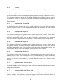
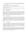
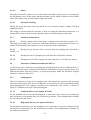
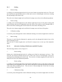
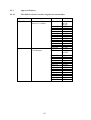
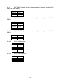
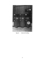
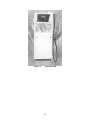
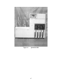
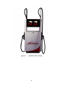
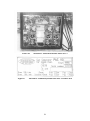
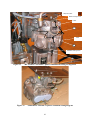
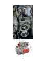
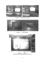
1
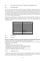
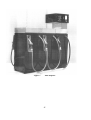
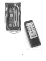
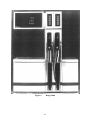
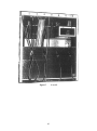
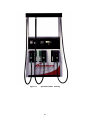
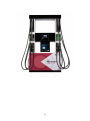
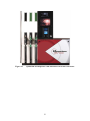
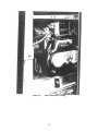
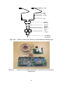
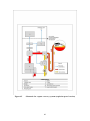
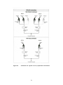
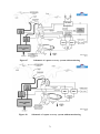
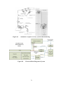
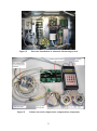
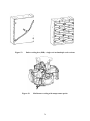
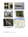
2286/80
III(5)a
Pursuant to section 12 of
the Weights and Measures Act 1985
Certificate No 2286/80 Revision 1
issued by:
The National Measurement Office
In accordance with the provisions of section 12 of the Weights and Measures Act
1985, the Secretary of State for Business, Innovation & Skills has issued this UK
national type-approval certificate to:
Tokheim UK Ltd
Unit 3
Baker Road
West Pitkerro Industrial Estate
Dundee, DD5 3RT
United Kingdom
and hereby certifies as suitable for use for trade the following pattern of a a liquid
flowmeter as described in the descriptive annex to this Certificate, and having the
following characteristics:DISPENSER:
Tokheim Elite dispenser as described in the descriptive annex.
POINT OF SALE
SYSTEMS:
As described in the associated certificates 2286/59.
The necessary data (principal characteristics, alterations, securing, functioning etc)
for identification purposes and conditions (when applicable) are set out in the
descriptive annex to this certificate.
Under the provisions of section 12(6) of the said Act, the validity of this certificate is
limited as shown below.
Note: This certificate relates to the suitability of the equipment for use for trade only
in respect of its metrological characteristics. It does not constitute or imply any
guarantee as to the safety of the equipment in use for trade or otherwise.
Issue Date:
Valid Until:
Reference No:
02 October 2014
26 October 2016
T1117/0027
Signatory: G Stones
for Chief Executive
National Measurement Office | Stanton Avenue | Teddington | TW11 0JZ | United Kingdom
Tel +44 (0)20 8943 7272 | Fax +44 (0)20 8943 7270 | Web www.gov.uk/nmo
NMO is an Executive Agency of the Department for Business Innovation & Skills
Descriptive Annex
1
INTRODUCTION
This pattern of an electrically driven meter comprises a dispensing unit operating in attended
stand-alone mode. It was originally manufactured by Schlumberger RPS Dunclare and
designated the Elite. It is now manufactured by Tokheim with several designations as listed in
this descriptive annex. The transaction data for each side is shown on the display and
computing head. The dispenser can indicate up to 999.99 litres giving an indication every 0.01
litres. The price-to-pay indication indicates up to £999.99 in intervals of £0.01. The unit price
increments every 0.1 pence per litre up to a maximum of 999.9 pence per litre.
The dispenser is of a modular design, with the master module comprising the electronics and
display head supported by a column as well as a hydraulic unit and hose retractor assembly.
The hydraulic unit is manufactured by Tatsuno and comprises a motor driven pumping unit
with integral air separator feeding two meters. The slave module comprises a hydraulic unit
and hose retractor assembly.
There may be up to four slave modules supported by the master module. This allows up to five
nozzles on each side of the dispensing unit. Electrical interlocks permit the use of only one
nozzle on a particular side of the dispenser at any one time. Any single nozzle may be used on
the opposite side of the dispenser at the same time.
This pattern is suitable for liquids other than water of low viscosity (<20mPa.s) except
liquefied gases. This includes ethanol blends up to 100% ethanol.
2
CONSTRUCTION
2.1
Mechanical (Figure 1)
The dispensing units are assembled using two types of hydraulics housings. These are a master module
and slave module, both of which contain the same hydraulic units, cabling and hose retraction
assemblies. In addition, the master module has a short column upon which is situated the
electronic calculator and display. Structural assemblies and paneiwork are constructed in steel.
Approximate Dimensions:Master module:
Slave module:
2.2
1565 mm high
1,140 mm high
510 mm wide
510 mm wide
470 mm long
470 mm long
Hydraulics (Figure 2)
The hydraulic unit comprises a motor driven pumping unit feeding two meters, and associated
air separators, non-return and pressure relief valves. The meter output pipes are routed via
solenoid valves to the hose retraction assemblies. There can be up to five such hydraulic
arrangements per dispensing unit.
2
2.2.1
Combined pump and air separator
The pumping unit is belt driven from an electric motor and has an integral air separator. The
pumping unit is manufactured by Tatsuno, and is designated the PGS-0257-H. This high speed
pumping unit is connected to two meters. The delivery rate is 45 L/min at each nozzle.
Fuel is drawn in via the inlet and passes through the strainer into the rotary pump. A by-pass
valve circulates liquid returning at a predetermined pressure to the pump inlet. Fuel passes
through the air separator where any air present is allowed to pass to the float chamber. The
float chamber houses a float operated valve that permits excess liquid to be returned to the
suction side of the pump. air is vented from the float chamber to the atmosphere via an
overflow protection valve. Liquid in the outlet chamber leaves the pumping unit via a check
valve.
2.2.2
Meter
The meter, designated type 02515-J, is a four-piston positive displacement type. The body of
the meter is made from aluminium alloy and the cylinders have stainless steel liners.
Calibration is by adjusting the stroke using an adjusting handle. This handle has a through hole
to accept sealing wire. The meter shaft rotates twice for every litre of fuel delivered.
2.2.3
Pipework
A pipe from each meter is routed via a solenoid valve to the hose retractor assembly. Each pipe
is then fixed to its respective hose, the hose terminating in a nozzle. Nozzles are stowed in
holsters along the sides of the hydraulics module.
2.2.4
Solenoid valve
A single-stage solenoid valve is fitted on the discharge side of each meter. When energised the
valve allows full flow of the liquid to the selected nozzle.
2.2.5
Nozzles
The following nozzles may be used:
Manufacturer
Elaflex
Elaflex
Elaflex
Elaflex
Elaflex
Elaflex
Elaflex
Elaflex
Elaflex
Model/Description
ZVA 4.4R for use with unleaded petrol
ZVA 4.4 for use with leaded petrol and diesel
ZVA 25.41 high flow nozzle for diesel
ZVA Slimline Drip Stop nozzle Minimum
Delivery 5 litres. (A legend indicating a 5 litre
minimum delivery will be marked on the spout
of the nozzle, this marking overrides that marked
on the dispenser).
ZVA Slimline 2
ZVA X204 GRV3G for use with unleaded petrol
ZVA X204 GRV3R-BL for use with leaded
petrol
ZVA X204M GRVP
ZVA Slimline 2 GR
3
Type
Automatic Shut-off
Automatic Shut-off
Automatic Shut-off
Automatic Shut-off
Automatic Shut-off
Vapour Recovery
Vapour Recovery
Vapour Recovery
Vapour Recovery
Manufacturer
Husky
Goodyear
Goodyear
Goodyear
Goodyear
OPW
OPW
OPW
OPW
ABR
2.2.6
Model/Description
Type ‘X’ series, single and double poppet
designs. Optional accessories including swivel
joints, sight glass option, and alternative spouts
and splash guards which may be fitted as
required.
GTR 50 for flowrates up to 50 litres /minute
GTR 80 for flowrates up to 80 litres /minute
GTR 120 for flowrates up to 120 litres /minute
GTR 50 VR
11 VAIE-0035 for use with unleaded petrol 11
VAIE-0037 is for leaded fuel.
11 VAIE-0037 for use with leaded petrol
12 EN (may be fitted with different sizes of
spout depending on the product type)
12 EN V (may be fitted with different sizes of
spout depending on the product type)
ABR 50 VR
Type
Automatic Shut-off
Automatic Shut-off
Automatic Shut-off
Automatic Shut-off
Vapour Recovery
Vapour Recovery
Vapour Recovery
Automatic Shut-off
Vapour Recovery
Vapour Recovery
Hoses
The following hoses may be used:
Manufacturer
Model
Elaflex, Germany
Elaflex, Germany
Elaflex, Germany
Elaflex, Germany
Good Year, USA
Good Year, USA
Good Year, USA
Conti – Slimline 25 Low temperature
Conti – Slimline 21 Low temperature
Conti – Slimline 16 Low temperature
Conti – Slimline 21 MPD
EN1360 TYPE 3 25mm 16 BAR M 1Q00 0310
EN1360 TYPE 3 16mm 16 BAR M 1Q99 0749
¾”Hardwall Petrol Hose
2.3
Maximum length
(Metres)
6
10
13
7
15
15
15
Electrical
2.3.1 Motor
The motors that drive the rotary pumps are single-phase or 3 phase, 1 HP rated.
2.4
Electronics
2.4.1 Pulser
On each meter output shaft is fitted a pulser which converts the rotary movement of the shaft to
electrical pulses. The pulser is a dual channel opto-electronic type that produces 200 pulses per
litre. The pulser is manufactured by Eltomatic and is designated type 0109. Also. a flexible
cable drive is coupled to a mechanical totaliser.
4
2.4.2
Display Head
The display head is supported from a column on the master module and contains the electronic
calculator, displays, power supply and motor switching circuits. These are all housed in a
fibreglass enclosure with a window in each side. Illumination is by fluorescent tubes.
2.4.3
Electronic calculator
The electronic calculator known as CoCa and comprises the following modules:
Uninterruptible power supply (UPS)
with external batteries
Maintains displays and transaction
information during power failure.
Calculator control module
Controls the hydraulic units and communicates
with kiosk equipment (if connected).
User interface module
Contains the transaction displays.
High voltage module
Interfaces to nozzle and motor switches.
Infra-red remote control module
In stand-alone mode this module allows dispenser
parameters to be set; unit prices etc.
2.4.4
Transaction displays
The dispensing unit contains two display boards, one on each side of the display head. The
board contains 7-segment Ferranti Packard electro-mechanical displays for price-to-pay (5
digit), volume (5-digit), and pence per litre (4 digit). Grade indication is by means of a LED
next to the appropriate grade indication legend.
2.4.5
Infra-red remote control (Figure 3)
When in stand-alone mode the dispenser configuration, unit prices etc. can be programmed by
means of the infra-red remote control. A key switch is located on the underside of the display
head. This key must be operated and a PIN code entered, via the remote control, before any
programming can be achieved.
If programming is attempted during a delivery ignores any instructions from the remote control
unit and continues as normal. Unit price changes are not possible whilst a delivery is in
progress.
2.4.6
Peripheral connection
Interfacing to peripheral equipment is provided via an RS232 port and to the kiosk control
equipment via a current loop.
5
2.5
Displays and legends (Figure 4)
The legends on the display face are given in the following table:
LEGEND
CHARACTER HEIGHT
£
This Sale
Litres
Pence per litre
See that indicator is at zero before
delivery commences
Minimum delivery 2 litres
18mm
15 mm
15 mm
5 mm
5 mm
5 mm
Legends associated with grade indication are 5 mm high and there is an illuminated pump
number 80 mm high. Additionally, there may be the following typical instructions adjacent to
the display face:
1
2
3
4
5
6
Remove fuel tank filler cap
Place nozzle in fuel tank
Squeeze trigger until required quantity is indicated or delivery stops automatically
Replace nozzle in holster
Replace fuel tank filler cap
Check indication and pay cashier.
2.6
Sealing (Figure 5)
2.6.1
Meter
The meter is sealed by means of a wire passed through a hole in the rim of the calibration
wheel, a hole in the locking pin and a hole in the head of a bolt securing the cover of the
calibrating cylinder. A wire passes through two bolt heads in each cylinder cover, one bolt
head in both the top and bottom meter covers and a hole in the dispenser frame.
2.6.2
Pulser
An adapter is fitted between the meter output shaft and the pulser shaft. A screw fixes the
adapter to the meter shaft and a further screw fixes the adapter to the pulser shaft. Each screw
head has a hole through which a sealing wire is passed, drawn taut, and then sealed.
3
OPERATION
3.1
Controls and features
On the underside of the computing and display head is a key switch. The operation of this key
switch allows the infra-red remote control access to the management programming mode once
a PIN number has been entered via the remote control.
6
3.2
Operating sequence
At the start of the transaction, the dispenser displays the previous sale. The attendant removes
the nozzle corresponding to the grade required on the side of the dispenser at which he is
standing. The displays show all 8s, blanks then zero. The grade selected and corresponding
unit price is displayed and the appropriate motor is started permitting a delivery to commence.
A second nozzle may be used on the other side of the dispensing unit. At the end of the
delivery the nozzle is replaced in the nozzle holster and the pump motor stops.
3.3
Interlocks and security features The following interlocks are provided:-
(i)
Only one grade can be selected at any one time and cannot be changed after a delivery
of 0.05 litres has occurred.
(ii)
The delivery is stopped if the pump detects an error condition.
In the event of a mains power failure, displays on the dispenser are maintained.
(iv)
A period of 5 seconds must elapse before a delivery of fuel can be authorised following
the replacement of the nozzle in the previous transaction.
(v) The unit price cannot be changed after any operation has been made on the dispenser to
initiate a transaction and before the expiry of the 5 second guard time (as iv).
The remote control cannot access the programming mode unless the key switch has been
operated and a PIN code is entered via the remote control, Access to the programming mode is
not possible during a transaction.
(vii)
It is not possible to enter a unit price below 32.4 pence per litre.
4
AUTHORISED ALTERNATIVES
4.1
Alternative Enclosure Arrangements
4.1.1
Having the dispensing unit, described in the certificate, with one, up to a
maximum of ten, hose(s) and associated nozzle(s). The hose arrangement may be with an equal
or unequal number of hoses on each side.
4.1.2
Having nozzles and displays fitted to one side of the dispenser only, in which
case the appropriate meters, encoders and valves are removed from the unit and that side of the
display case is blanked.
4.1.3
Having a single-product, single-hose high speed version. where the Tatsuno
hydraulic unit described at Section 2.2 feeds one meter only. The hydraulic unit is contained
within the master module.
4.1.4
Having a single-product two-hose high speed version, where the Tatsuno
hydraulic unit described at Section 2.2 feeds one meter only. The master module contains one
hydraulic unit and the hose assembly. The other hydraulic unit is contained within a slave
module which has no hose assembly
7
4.1.5
motor.
Having the single-phase motor described at Section 2.3 replaced by a 3-phase
4.1.6
Having the mechanical totalisers removed from the pullers.
4.1.7
Having submerged or remote hydraulics, in which case the motors and pumping
units are removed from the hydraulic enclosure. However, the meter described at Section 2.2.2
will remain within the enclosure.
4.1.8
Having the grade indication removed.
4.1.9
Having two dispensing units in a satellite configuration, the satellite unit
housing is as described in the Certificate. However, the unit contains no hydraulic components
other than a single stage solenoid valve and retractable hose unit.
4.1.10
Having a dispenser that is capable of delivering at two flow rates. The higher
flow rate is approximately 80L/min and the slow flow rate is approximately 40 L/min.
4.1.11
Having fitted to the dispenser push-buttons that allow the purchaser to preset by
either volume or price a specific delivery amount. There are two buttons that select the
required volume or price. These buttons may have any value and each operation increments the
preset amount by their respective values. A third `CLEAR ALL' button is included which
cancels the total preset amount and allows another to be entered. This button is only
operational up to the point of lifting the nozzle.
4.1.12
Having a volume only display.
4.1.13
as adblue.
Having a separate delivery system fitted for delivering non-fuel products such
4.2
Alternative Enclosure Styles
4.2.1
2000 Range
As described in the Certificate but having the Range 2000 dispenser housing as shown in
Figure 6. The display head is enlarged and mounted on top of heightened hose retraction units,
which are all mounted adjacent to each other. An additional smaller hydraulic housing is
positioned on the opposite side of the hose retraction units in configurations of 4. 6. 8 and 10
hose dispensing units.
4.2.2
Level 5
As described in the Certificate but having the Level 5 dispenser housing as shown in Figure 7.
The display head is mounted on one of the support columns for the hose canopy.
4.2.3
Industrial Cladding
Having the enclosure modified as shown at Figure 8. The cladding may be manufactured of
glass fibre or metal.
8
4.2.4
Pegasus
As described in the certificate but having the Pegasus housing as shown in Figure 9
4.2.5
Optima
As described in the Certificate but having the Optima dispenser housing as shown in Figure 10.
The calculator housing on Optima has an outside cladding of steel and is in halves. Each of
which may be opened for access to the calculator, An additional smaller hydraulic housing is
positioned on the opposite side of the hose retraction units in some configurations of hose
dispensing units.
4.2.6
Quantium 100, 300 and 500
As described in the Certificate but having a range of dispenser housings under the generic
name of Quantium. These are built using the same standard sub assemblies but with different
hose and product combinations.
4.2.6.1
Quantium 100 (Figure 11)
The calculator housing of the Quantium 100 is situated between two columns 340mm above
the hydraulic housing. The dispenser columns and hydraulic housing are steel sheet punched
and folded into modular units. Hoses are hung from either, spring actuated rope retraction
units, or stowed on a simple hook. Nozzle holders are in the columns (island) configuration.
4.2.6.2
Quantium 300 (Figure 12)
The calculator housing of the Quantium 300 is situated between two columns 340mm above
the hydraulic housing. The dispenser columns and hydraulic housing are steel sheet punched
and folded into modular units. Hoses are hung from either fixed or flexible hose masts. The
nozzle holders may be either in the hydraulic housing doors or in the columns.
4.2.6.3
Quantium 500 (Figures 13)
The calculator housing of the Quantium 500 is situated partially on the hose cassettes and on a
blanking unit for a future card reader, adjacent to the calculator housing is a space fill unit for
advertising. The card reader is situated above the hydraulic housing containing the solenoid
housing, this housing is situated above an extended hydraulic housing that is adjacent to the
cassettes.
4.2.7
Quantium 300T, 400T and 500T
As described in the certificate but having a range of dispenser housings under the generic name
of Quantium T. These are built using the same standard sub assemblies but with different hose
and product combinations.
4.2.7.1
Quantium 300T model (Figure 14)
Having the Quantium 300 dispenser as described above modified with minor dimensional and
cosmetic changes. This is primarily a change in footprint from 750mm x 500mm to 830mm x
520mm. The model is identified as the Quantium 300T.
9
Materials are similar to those used on the existing Quantium 300 model. The majority of
cladding panels, including the calculator housing and doors, are constructed from mild steel.
The use of plastic components for external panels is limited to the nozzle boots, as used on the
existing Quantium 300 and 500 models.
4.2.7.2
Quantium 400T model (Figure 15)
Having the Pegasus model as described above identified as the Quantium 400T. The model
may optionally use the plastic nozzle boots of the Quantium 300T or 500T.
An integrated payment terminal may be installed providing this certificate has approved its use.
4.2.7.3
Quantium 500T model (Figure 16)
Having the Quantium 500 dispenser as described above modified with minor dimensional and
cosmetic changes. This is primarily a 100mm increase in height of the hydraulic housing, and
single product models no longer include a ‘dummy’ hose retractor along side the populated
hose retractor. The model is identified as the Quantium 500T.
Materials are similar to those used on the existing Quantium 500 model. The majority of
cladding panels, including the calculator housing and doors, are constructed from mild steel.
The use of plastic components for external panels is limited to the nozzle boots, as used on the
existing Quantium 300 and 500 models.
An integrated payment terminal may be installed providing this certificate has approved its use.
4.2.8
Quantum 100T and 200T
As described in the certificate but having two alternative enclosures for the hydraulics and
calculator used on the Quantium 300T dispenser as described above. These two alternative
enclosures are named the Quantium l00T and Quantium 200T, and are built using the same
standard sub assemblies but with different hose and product combinations.
4.2.8.1
Quantium 100T model (Figure 17)
Models may only dispense a single product. Models may have displays for Price to pay,
Volume. and Unit price, or models are available with a Volume only display. The display is
mounted on one side of the dispenser only
4.2.8.2
Quantium 200T model (Figure 18)
Models may dispense one or two products through individual hoses. All mode1s are designed
for retail use with displays for Price to pay, Volume, and Unit price. Displays may be mounted
on one side of the dispenser or both.
4.2.9
Quantium 200T twin series dispenser with hydraulics for removing fuel
from vehicle fuel tanks (De-bowser unit)
As described in the Certificate but having the hydraulics serving one side of the dispenser
replaced with hydraulics for withdrawing fuel from vehicle fuel tanks. The pulser and
associated electronics in the headworks remain unaltered. The hydraulic arrangement is shown
in Figure 19.
10
NOTE: The de-bowser section is not approved for trade use but is intended for wetstock
reconciliation purposes only. A label is fixed to this section that clearly displays the
following text:
FOR WITHDRAWING FUEL ONLY. NOT FOR TRADE USE
The hydraulic components of the dispenser and the de-bowser are separate with the de-bowser
display showing volume only.
The dispenser may only be operated in a self contained mode or with self-service devices
approved for registered users only.
4.2.10
Quantium 410
As described in the certificate, but having an alternative dispenser enclosure designated
Quantium 410 (Figure 20). This is similar to the Quantium 400T model described above; but
having the electronics enclosure supported between the dispenser columns, and an airspace
between the top of the hydraulic housing and the underside of the electronics enclosure. The
upper halves of the dispenser columns may include a hose retraction mechanism. A payment
terminal enclosure may be fitted to the underside of the main calculator enclosure.
4.2.11
Quantium 510
As described in the certificate, but having an alternative electronics enclosure for the Quantium
510 model (Figure 21). The dispenser is visually similar to the Quantium 500T model
described above; but having a larger electronics enclosure, which extends down to the height
of the hydraulic top housing. The upper door to the enclosure supports the primary display and
an optional separate video display, which may be used for non-metrological purposes such as
advertising. A payment terminal enclosure may be fitted to the underside of the main calculator
enclosure.
4.2.12
Quantium 510C
As described in the certificate but having , but having an alternative arrangement for the hose
management system and electronics enclosure as shown in figure 22. The dispenser is similar
to the Q500T as described above, using the same style of hydraulics cabinet, hydraulic
components and calculator. The hose management cassette uses a single vertical column
instead of smaller multiple individual hose cassettes. The grades are separated using partitions
fitted external to the single hose cassette column.
The electronics enclosure is located within a safe area above the hydraulics cabinet, on the end
column of the hose management cassette. Any approved payment terminal under 2286 may be
fitted as an option. The type designation may be known as Quantium 510C, Q510C, Q510n
where n is an alphanumeric character used to reflect particular key features such as the hose
management cassette or style of electronics enclosure.
11
5
ALTERNATIVE HYDRAULICS
5.1
Alternative Schlumberger hydraulics (Figure 23)
As described in the Certificate but having all the Tatsuno hydraulic units replaced by
Schlumberger PAS hydraulic units. This hydraulic unit comprises a motor driven pumping
unit. with integral air separator and gas detector. feeding two meters and associated nozzles.
The maximum flowrate is approximately 55 litres per minute.
5.1.1
Pumping unit
Fuel is drawn in via a filter. through a check valve, into the rotary gear pump and then passes
through an air separating vortex. Fuel with a small amount of entrapped air then passes to the
main air separation chamber. Any remaining air is vented to atmosphere via an air vent check
valve and fuel is passed to the nozzle.
If the amount of air entrapped in the fuel passing through the pumping unit is greater than a
predetermined value the gas detector operates and causes the fuel flow to cease.
This pumping unit may be fitted in conjunction with any meter described in this certificate.
5.1.2
Meter
The Schlumberger SMIOO meter consists of two pistons which move horizontally and
transmit their movement to the pulser by means of crank pins. The meter adjustment is made
by adjusting the stroke of the pistons at one end. The meter adjustment wheels are covered and
sealed. The meter has a drive ratio of two revolutions per litre.
5.1.3
Pulser
As described in section 2.6.2.
5.1.4
Sealing (Figure 24)
5.1.4.1
Meter
The meter is sealed by means of a wire which passes through a loop in the serial plate, then
through a hole on the top cover and through concentric holes on the meter body and back
cover. It then passes through a hole in the meter body, a hole in the bottom cover. to the other
side of the meter and passes back to the loop in the serial plate. via a similar route described
above. and is then drawn taught and sealed.
A second wire passes through a screw on the cover of the calibration wheel and then through a
hole in the cover itself. It is then drawn taught and sealed.
The meter and pulser assembly are also sealed to a horizontal plate. A wire passes through all
the assembly fixing screws and a separate screw fixed to the plate. it is then drawn taught and
sealed.
12
5.1.4.2
Pulser
The pulser is sealed by means of a wire which passes through a special seal screw securing the
top and bottom covers of the pulser and then through a screw which is fastened to the bottom
cover of the pulser only. It is then drawn taught and sealed.
5.1.4.3
Alternative Sealing
Having the meter and pulser sealed by means of a wire routed as shown in figure 25 drawn
taught and sealed.
The sealing as shown should be such that, as well as sealing the individual components, it is
not possible to remove them from the dispenser frame without breaking a sealing wire.
5.1.3
Authorised Alternatives
5.1.3.1
Having a single meter being fed by a pumping unit described at section 5.1.1.
This high speed single hose version has a maximum flowrate of approximately 80 litres per
minute. The remaining of the hydraulic unit is as described in this amendment.
5.1.3.2
Having the gas detector device removed from the pumping unit described at
section 5.1.1
5.1.3.3
Having the PAS 130 pumping unit with max flow of 80 litres a minute.
5.1.3.4
Having the-PAS 130/8 pumping unit with a max flow of 130 litres per minute
5.2
Alternative Tokheim hydraulic unit PAS V3
As described in the Certificate but replacing the existing hydraulics with the Tokheim PAS V3
hydraulic unit that can be configured with different combinations of meters and nozzles to give
different maximum flow rates (Qmax). A typical arrangement within the alternative Pegasus
enclosure is shown in Figure 26.
5.2.1
Pumping unit
This unit comprises a motor driven pumping unit, with integral air separator and associated
non-return and pressure relief valves, feeding one or two meters, directly mounted horizontally
on the pumping unit. The complete assembly can be identified by the ‘sticker’, as shown in
Figure 27, attached to the body of the pumping unit.
5.2.1.1
Standard delivery rate (Qmax 40 L/min)
For the standard delivery rate the pumping unit is connected to two meters each feeding one
hose and nozzle at a maximum flow rate of 40 litres per minute. This configuration is suitable
for use with petrol and diesel.
5.2.1.2
High speed delivery rate (Qmax 80 L/min)
For the high speed delivery rate the pumping unit is connected to one meter feeding one hose
and nozzle at a maximum flow rate of 80 litres per minute. This configuration is suitable for
use with petrol and diesel.
13
5.2.1.3
Super high speed delivery rate (Qmax 130 L/min)
For the super high speed delivery rate the pumping unit is connected to two meters feeding one
hose and nozzle at a maximum flow rate of 130 litres per minute. This configuration is suitable
for use with diesel only. The minimum delivery is 5 litres.
5.2.2
Sealing (Figure 28)
The meter is sealed by means of a wire, which passes through tabs and cast bosses on the sheet
metal and cast components of the pump meter and pulser.
I. Pulser;
A seal wire passes through two sets of aligned holes in the body and lid of the
pulser. The holes are in diagonally opposite corners of unit and the seal is made close to one of
the corners.
II & III. Meter;
The wire first threads through the lead seal then to a hole in the bell
housing flange of the meter on to a tab with hole on the pulser gear retaining plate, round to the
back plate of the meter through aligned holes in the meter body and back plate. The wire now
passes through two similarly positioned holes in two corners of the bottom plate then returns
via another hole in the back plate to bell housing and on to a second tab/hole in the pulser gear
plate, and finally to the lead seal.
IV. Calibration wheels, and meter to dispenser;
A wire is passed from the seal through a
hole in the calibration cover then the cover securing screw to a hole in the pumping unit top
and back to the seal.
V. Blanked pump port (where only one meter is installed) A wire is passed through holes in
the nut end of the two securing bolts preventing their removal or rotation. The seal is made
between the two bolts.
All seal wires are drawn taut through all the holes prior to sealing
5.2.3
Authorised Alternatives
Having the PAS V3 combined pump and air separator unit described but having a modified
vortex valve and outlet non-return valve. This is identified by a data plate that references
OIML certificate number “OIML R117-95-NL-01.04”.
5.3
29)
Alternative Tokheim combined pump and air separator unit EPZ (Figure
Having the dispensers as described in the Certificate but replacing the existing pump and air
separator unit with the Tokheim EPZ pump and air separator unit. This can be configured with
different combinations of meters and nozzles to give different maximum flow rates (Qmax)
14
5.3.1
Construction
This unit comprises a combined rotary pump and air separator known as the model EPZ. Fuel
is drawn into the pump via an inlet strainer, and through a checkvalve prior to entering the
pumping section. The pump is based upon a rotary vane device, and the unit includes a bypass
circuit controlled by a mechanical spring valve. Within the pump discharge circuit, all fuel
passes under pressure through a centripetal air separator, and finally through a non-return valve
to the discharge port.
Separated air is vented to atmosphere via the air vent, and any liquid is returned to the inlet
side of the pump via a float valve within the air separation chamber.
5.3.2
Standard delivery rate (Qmax 40 L/min)
For the standard delivery rate the pumping unit is connected to two meters each feeding one
hose and nozzle at a maximum flow rate of 40 litres per minute. This configuration is suitable
for use with petrol and diesel.
5.3.3
High speed delivery rate (Qmax 80 L/min)
For the high-speed delivery rate the pumping unit is connected to one meter feeding one hose
and nozzle at a maximum flow rate of 80 litres per minute. This configuration is suitable for
use with petrol and diesel.
5.4
Alternative Tokheim Meter MA26 and Pulser MP-T1 (Figure 30)
Having the dispensers as described in the Certificate but having the Tokheim Meter MA26 and
the Pulser MP-T1 combination fitted to the Tokheim PAS V3 or the EPZ or PAS 130 pump
and air separator units
5.4.1
Meter
The meter is the Tokheim model MA26. This is a positive displacement device with four
horizontal pistons. The meter output shaft, which rotates once very 0,7 litres, is directly
connected to the pulser model MP-T1. Calibration is provided by moving a lever on a notched
quadrant at the base of the meter, which adjusts a cam acting on the four pistons. Each step is
approximately 0.1%.
5.4.2
Pulser
The pulser is a Tokheim type MP-T1, which generates 100 pulses per litre. This is bolted to the
meter and directly couples to the meter output shaft. This is similar to the MP1 pulser used
with the SM80 meter described in certificate 2286/13 but the gearing is modified to output 70
pulses per revolution and to account for the MA26 meter rotating in the reverse direction to the
SM80 meter.
15
5.4.3
1
Sealing
Piston sealing
A sealing wire feeds through the head of a seal screw fitted in each piston end cover. This seal
wire also diverts upwards between two of the end covers to feed through a seal screw securing
the top housing to the meter body.
The seal wire is drawn taught and a seal fixed for stamp access above the calibration quadrant.
2
Pulser sealing
A sealing wire feed through holes in the bottom right hand corner of the pulser casting and
meter housing, then travels diagonally across the front of the pulser to pass through either a
hole in the meter mounting plate or the head of the front meter mounting screw.
The seal wire is drawn taught and a seal fixed for stamp access in front of the pulser.
3
Calibration sealing
A seal wire passes through holes in the calibration locking screw drawn taught and a seal fixed.
4
Meter sealing
The meter is sealed into the dispenser by passing a seal wire through the heads of two of the
meter mounting screws.
The seal wire is drawn taught and a seal fixed for stamp access on the top of the hydraulic
stack.
5.4.3.1
Alternative Sealing of MA26 meter and MP-T1 pulser
The following numbers refer to Figure 31:1
Piston sealing
Sealing wire feeds through the head of a sealing screw fitted in each piston end cover. This
seal wire also diverts upwards between two of the end covers to feed through a seal screw
securing the top housing to the meter body. The seal wire is drawn taught and a seal fixed for
stamp access above the calibration quadrant.
2
Pulser sealing
A sealing wire feeds through holes in the bottom right hand corner of the pulser casting and
meter housing, then diagonally across the front of the pulser to pass through a hole in the head
of the front meter mounting screw. The seal wire is drawn taught and a seal fixed for stamp
access in front of the pulser.
3
Calibration sealing
A seal wire passes through holes in the calibration locking screw drawn taught and a seal fixed.
16
4
Meter to frame sealing
The meter is sealed to the frame of the dispenser by passing the pulser seal wire (described in
2) through the head of the front meter mounting screw.
The following numbers refer to Figure 32:1
Meter sealing
The meter is sealed in to the frame of the dispenser by passing a seal wire through the heads of
two meter mounting screws then drawing taught and fixing a lead seal.
2
Pulser sealing
A sealing wire passes through two sets of aligned holes in the body and lid of the pulser. The
holes are in diagonally opposite corners of the unit and the seal is made close to one of the
corners.
3
Housing, piston, and bottom plate sealing
A seal wire passes through a lead seal then through a hole in the meter top housing flange to a
tab with a hole on the pulser gear retaining plate, round to the back of the meter through
aligned holes in the meter body and back plate. The wire now passes through two similarly
positioned holes in two corners of the bottom plate then returns via another hole in the back
plate to the meter top housing flange and to a second tab/hole in the pulser gear plate, and
finally returns to the lead seal.
4
Calibration sealing
A seal wire passes through the head of the calibration cover securing screw and a hole in the
cover, the wire is drawn taught and a lead seal fixed
5.5
Quantium dispenser models with TQP pumping unit and TM80 meter
Having the TQP pump and TM80 meter fitted to the Quantium dispenser models. The
dispenser may be renamed in order to highlight the alternative hydraulics being employed as
defined in the following table:
Existing Model Name
Q100T
Q200T
Q300T
Q400T
Q500T
Q410
5.5.1
Alternative model name
with new hydraulics
Q110
Q210
Q310
Q400T (name unchanged)
Q510
Q410 (name unchanged)
TQP pumping unit
As described in the Certificate but having the air separator lid of the EPZ pumping unit
reduced in height, and a casting added to the pump outlet port. This casting allows direct
connection to one or two meters. The pumping unit is designated TQP.
17
5.5.2
TM80 meter
As described in the Certificate but having internal modifications to the SM80 meter which
reduces drift over the meter lifespan. This meter is designated the TM80 meter.
The TQP pumping unit and TM80 meter are shown in Figure 33
5.6
TQM meter
Having the TQM meter fitted. This meter is similar to the TM80 meter as above but with
modifications to the piston seals (Figure 34).
The meter may be used for dispensing traditional petrol and diesel products; but may also be
used for dispensing biodiesel blends of up to 20% biodiesel, and ethanol petrol blends of up to
15% ethanol. The aluminium components may optionally be anodised resulting in a dark grey
external finish. The meter will typically dispense an 85 % ethanol blend, but may dispense up
to 100% ethanol. This is shown on the component label with the added reference, “For use
with E85.” This is subject to the bio-fuels not having excessive water content.
With this meter the models may optionally carry the alternative names Q110, Q210, Q310,
Q410, and Q510 in order to highlight alternative hydraulics being employed.
6
ALTERNATIVE ELECTRONICS
6.1
Model 6 Alternative Display head electronics
The electronic calculator known as Model 6 comprises the following modules:
a
Battery backed
Power supply
b
Computer Board
-
Power to calculator and displays
Controls Hydraulic modules and communicates with
Kiosk equipment
c
6.2
Multiplexor Board
-
Interfaces nozzles pulsers and solenoids to computer
board
Opto isolator
As described in the certificate, and any compatible variants thereof, but having a Veeder Root
single channel opto isolator. The device provides an optically isolated RS232 interface and
connects any tank gauging system to any Kiosk Control Unit, or any Point of Sale Terminal
approved under this certification for connection to the KCU, or any DOMS controller which is
approved under this certification or any compatible variants with an existing RS232 output port
and having a current valid until date. The device allows communication of tank related data.
The tank gauging system provides the power source for the opto isolator.
This opto isolator is primarily intended for the connection of a tank gauging system. However
there may be any peripheral equipment connected to the opto isolator in use for management
purposes only. The peripheral equipment must provide the power source for the opto isolator.
18
The label on the opto isolator bears the part number 700-017-1010, an alternative design of the
opto isolator bears the part number 700-017-1011, as shown in Figure 35.
6.3
World Wide Calculator (WWC)
6.3.1
Introduction
Having the dispensers as described in the Certificate but replacing the existing calculator head
with the World Wide Calculator.
6.3.2
Construction
6.3.2.1
Calculator (Figure 36)
The electronic calculator known as the WWC comprises of the following:a)
Power supply unit HVU
Identification No: COC OEL 046._
Incorporates rechargeable batteries and maintains display and transaction information during a
power failure.
b)
Main board HCM
Identification No: WWC OEL 001._
Incorporates the calculator module and controls the hydraulic units and communicates with the
communication adapter board COM, and the nozzle bus board NBB, both of which are
mounted on the main board.
c)
Communication adapter COM
Identification No: WWC OEL 007._
Interfaces the dispenser operation to self-service equipment.
d)
Nozzle switch bus NBB (optional)
Identification No: WWC OEL 012._
Interprets the signals from the nozzle switches.
e)
Incoming and outgoing board I/O
Identification No: WWC OEL 002._
Converts, controls and distributes the signals from the hydraulics unit (pulsers,valves,motors)
and communicates with the main board.
f)
User access board (optional)
Identification No: WWC OEL 005._
In stand-alone mode this allows the dispenser to be set (unit prices etc), using the infra-red
handset control unit.
6.3.2.2
Transaction display (Figures 37)
The calculator contains two display boards, one on each side of the display head.
The boards contain 7-segment electro-mechanical or liquid crystal displays for price to pay (5digits of 25mm height), volume (5-digits of 25mm height), and pence per litre (4-digit of
12mm height).
19
6.3.2.3
Handset control unit
The dispenser may be set up using either, a remote infrared handset, or a handset, which plugs
in to the calculator main board. These handsets are used to set up local configurations, fuel unit
prices etc. It is also possible to have readout of totals and errors.
6.3.2.4
Optional LON Interface
Having the Communication adapter COM board "WWC OEL 007" replaced with the LON
interface board "WWC OEL 003". This allows communication to approved forecourt control
systems using the IFSF protocol.
6.4
World Wide Calculator T1 (WWC–T1)
6.4.1
Introduction
The WWC- T1 differs from the WWC in that the nozzle switch bus board (NBB) is no longer
used, the functions of this are now incorporated in the Main board (HCM).
The Main board and the Incoming and outgoing board are now enclosed in a moulded plastic
housing which is fixed to the calculator chassis plate.
6.4.2
Construction
6.4.2.1
Calculator (Figures 38 and 39 )
The electronic calculator known as the WWC-T1 comprises of the following:a)
Power supply unit HVU
Identification No COC OEL 046._
Incorporates rechargeable batteries and maintains display and transaction information during a
power failure.
b)
Main board HCM
Identification No WWC OEL 001._
Incorporates the calculator module, controls the hydraulic units, interprets the signals from the
nozzle switches, and communicates with the communication adapter board COM which is
positioned outside the plastic cover and mounted on to the main board through holes in the
plastic cover.
c)
Communication adapter COM
Identification No WWC OEL 007._
Interfaces the dispenser operation to self-service equipment.
d)
Incoming and outgoing board I/O
Identification No WWC OEL 002._
Converts, controls and distributes the signals from the hydraulics unit (pulsers,valves,motors)
and communicates with the main board.
e)
User access board (optional)
Identification No WWC OEL 005._
In stand-alone mode this allows the dispenser to be set (unit prices etc), using the infra-red
handset control unit.
20
6.4.3
Optional LON Interface
Having the Communication adapter COM board "WWC OEL 007" replaced with the LON
interface board "WWC OEL 003". This allows communication to approved forecourt control
systems using the IFSF protocol.
6.5
World Wide Calculator 1.1 (WWC–1.1 EIO/EST)
As described for the WWC-T1 but with the following updated components:
6.5.1
Alternative Components
PART
Basic I/O Board
Pre processor module
ARM9 Processor Board
Hydraulic Module Board
Hydraulic Module Board (Cortex based)
Display Boards
VGA Display Devise
Slave I/O Board
Power Supply Boards
Impulse Encoders
IFSF Lon Interface
IFSF LONC Interface
EIN Interface
UDC Interface
Logitron Interface
EPS/Dresser Interface
ZSR/Dunclare
GIL Interface
PT100 Temperature Sensor
IDENTIFICATION
TQC-EST/TQC 030L0 or
TQC EIO4/TQC 001L3
With EI04 only
TQC APB3/TQC 011L3
TQC-HYM
TQC-HYM6/TQC 002L6
TQC-CS01-PPU/TQC 027L1
TQC-CSD3/TQC 014L3
iBase M1910E(F) or
Avalue EMX-GM45
TQC-S101/TQC006L1
TQC-PSU 2/TQC 005L2
TQC-PSU5/TQC 005L5
TQC-MPL3
TQC-MPC3
TQC-MPC5
TQC LON3/TQC 007L3
TQC LON4/TQC 007L5
TQC-008
TQC-012
TQC-009
TQC-EPS1
TQC-029
TQC-031L
Atexis 909545
21
6.5.2
Approved Software
6.5.2.1
The ARM-9 software contains 4 legally relevant modules:
Application name
IibTqcWM.so
DisplayHdl.Arm
description
version
Calculation for "amount = 00.001.02
unit price X volume"
01.000.07
02.000.07
02.001.07
02.003.7
03.000.07
04.000.07
05.001.08
05.002.08
05.006.08
05.008.08
06.001.08
07.005.08
07.006.08
Interface to the C5D and 00.001.04
VGA Manager
00.006.09
00.006.10
00.006.11
0'1.000.15
02.000.16
02.001.16
02.003.16
03.000.17
04.000.'19
05.001.23
05.002.23
05.006.24
05.008.25
06.001.25
07.005.27
07.006.27
22
checksum(s)
00008A76;
0x6340;
0x6350
Ox77CA
OxF6FF
0xF714
OxF6FD
0x464D
0xA392
0x4E88
Ox4E4F
0x214E
0x2842
Ox6DA7
0x33A4
Ox7F90
OOOOC316
OxCB52;
Ox5EDC
0x949A
0x7B46
OxFD62
OxFF74
OxFF8C
OxFF6E
Ox2EFF
Ox3 E E3
0x4C86
0x4B37
Oxl5E5
0x5C87
0x9564
OxE17E
0x3329
Application name
VgaMgr.Arm
_ 1.2.12
6.5.2.2
6.5.2.3
description
version
Interface to the VGA
display
00.006.31
00.00632
00.006.33
Pre processor (PPE) software
00.006.38
00.006.41
00.006.42
01.000.59
02.000.60
02.003.60
03.000.60
04.000.67
05.001.74
05.003.75
05.006.75
05.008.77
06.001.77
07.005.81
07.006.81
IFSF_srv.Arm
TCP IFSF pump controller 00.000.02
interface
00.000.03
00.000.03
00.000.03
00.000.04
Pre processor (PP) software (for WWC1.1 E10)
Application name
description
version
PP
Pre-processor module
00.001.31
00.006.42
00.006.44
01.000.50
02.000.52
03.000.54
05.000.58
05.000.65
06.000.68
06.000.70
07.000.73
07.001.75
07.003.76
checksum(s)
00005616
Ox2F17
Ox4BB6
OxBDC6
0x6867
0x4C25
0xE851
0x6084
0x6084
0x62E8
OxEF76
0x4515
OxEE2D
0x9890
Ox62EB
0xB899
Ox3FF8
0xE268
OxOB06
OxOC41
0x0E39
0x253B
OxDB3D
checksum
0000454F
OxBB57
0x1 E45
OxA9A4
Ox5E8F
OxA7C4
OxBF07
Ox8CC9
OxE1FB
Ox1 DC9
0x85F4
OxCC80
OxEE38
Pre processor (PPC) software (for WWC1.1 E1O)
Application name
description
version
checksum
PPC
Pre-processor module
06.000.68
OxDD4F
06.001.72
0x8C3F
07.000.73
0x961 F
07.003.76
OxA572
23
6.5.2.4
Pre Processor (PPE) Software
Application name
description
PPE
Pre-processor module
6.5.2.4 Pre processor (PPCE) software
Application name
description
PPCE
6.5.2.5
05.000.58
06.000.68
06.001.72
07.001.75
07.003.76
version
06.000.68
06.001.72
ST software (only for the WWC1.1 EST)
Application name
description
version
_
ST
6.5.2.6
Pre-processor module
version
Single twin software
05.001.05
06.001.08
07.001.16
08.000.19
08.000.20
STE software (only for the WWC1.1 EST)
Application name
description
version
STE
Single twin software
24
05.001.05
06.000.06
06.001.08
07.001.15
08.000.19
08.000.20
checksum
0x39B8
OxDD4F
OxEECD
Ox6FB5
0x86E5
checksum
OxE2A7
Ox4C5E
checksum
0x0327
0xE 199
Ox8E6E
OxCC84
OxCCA7
checksum
OxFDC5
OxEB9C
0x34A5
OxCDEO
OxCDEO
Ox1 FDF
6.5.2.7
Indicating devices software
Application name
CSD
version
CAN based LCD display _ 00.001.03
00.006.15
02.000.27
03.000.30
05.001.38
05.000.39
05.001.39
06.00040
07.001.42
CAN based LCD display 05.001.11
(Cortex based)
06.001.15
07.000.16
07.001.17
07.002.18
VGA screen (Ethernet
00.008.00
connected)
00.008.04
00.008.08
00.008.12
00.001.04
01.000.00
02.000.00
04.000.03
04.001.00
05.001.00
05.002.00
05.003.00
05.005.00
05.008.00
07.002.02
07.002.03
CSDC
VGA
6.5.2.8
description
checksum
00008671
OxD83B
Ox6FF3
OxEF7A
OxA1 FA
0x97E3
0x97E3
Ox1F6F
Ox6B6B
OxDEE3
OxC2DB
Ox7F74
Ox550E
OxFCO1
0x3B551A95
OxC74AAB23
0x97CB865A
0x2764D6EB
0x70C7 E761
0x8331 D612
Ox480A82DD
OxE1D2A9C7
0x3475B699
Ox1A3OF1FB
OxEFA1O201
Ox30CBA253
0x870E5B36
OxD30A4F70
OxFC2DD913
Ox6064E 1 CD
TQC-MPC3 and TQC-MPL3 impulse encoder software.
version
00.001.15
00.006.20
00.007.23
01.000.27
02.000.28
05.000.32
05.001.36
06.000.37
06.001.42
07.001.44
07.001.17
07.003.48
checksum
00006371
0x5115
0x2885
Ox38FD
0x86E4
OxED33
0x5C26
0x7363
OxF786
0x768C
0x4781
0x5326
25
6.5.2.9
TQC-MPCE impulse encoder software (applies to impulse encoders TQCMPC3 and TQC-MPL3).
version
05.000.32
05.000.37
06.001.42
07.001.44
6.5.2.10
MPC5).
TQC-MPCC impulse encoder software (applies to impulse encoder TQC-
version
05.001.36
06.000.37
06.001.42
07.001.44
07.003.48
6.5.2.11
MPC5).
checksum
0x0930
Ox9D66
OxF362
, 0x87A7
checksum
Ox653F
0x8006
Ox6D8F
OxDF32
OxAE94
TQC-MPCCE impulse encoder software (applies to impulse encoder TQC-
version checksum
06.000.37 0x9225
06.001.42 Ox1B1F
07.001.44 0x5851
6.5.2.12
TQC-LON interface.
version
00.001 A6
00.001.10
02.00014
03.000.16
04.000.18
07.001.22
6.5.2.13
checksum
0000AEDB
OxA7D7
OxF4F6
0x9291
Ox92C8
0x92C8
TQC-LONC interface.
version
05.000.14
05.000.15
06.001.21
07.001.23
checksum
OxACEA
OxBAD8
Ox108B
OxD669
26
6.5.2.14
EIN interface.
version
00.007.04
02.000.07
02.000.13
03.000.14
05.000.17
05.001.21
05.001.23
06.000.24
07.001.26
07.003.29
08.000.30
08.000.31
6.5.2.15
UDC interface.
version
03.000.12
03.000.15
04.000.19
05.000.23
05.000.25
05.000.26
05.000.29
05.001.37
05.001.38
06.001.43
07.001.45
07.002.50
08.000.54
6.5.2.16
checksum
0x029D
Ox6E4A
0x9638
Ox28BA
0x9393
OxF69F
0x3C 15
0xD624
0x43C8
0xF503
0x999D
0x8332
checksum
0x122D
0x35C7
Ox51 F5
OxF75A
Ox996B
0x9973
Ox51 C8
0x1 C50
0x211 C
0x9725
OxF709
OFEE9
0x42F9
UDCC interface.
version checksum
06.000.41 Ox5FCF
07.001.45 0xC267
6.5.2.17
Logitron interface.
version
03.000.03
05.000.11
05.001.14
06.001.16
07.001.17
checksum
OxB7F7
0x4A98
Ox5E7A
0x1 D18
0x4781
27
6.5.2.18
EPS / Dresser interface.
version
05.000.06
05.000.12
05.000.14
05.001.16
06.001.20
07.001.21
07.001.22
6.5.2.19
ZSR / Dunclare interface.
version
05.000.06
05.001.09
06.000.10
07.001.11
08.000.19
08.000.21
08.000.22
6.5.2.20
checksum
Ox3ED7
OxB6B7
0x3908
OxD7A5
OxlOD8
Ox11AF
Ox45BA
checksum
Ox15F7
OxC28D
Ox3DDB
Ox2A15
OxC1 EC
OxBB47
OxADBB
GIL interface.
Version
07.000.00
Checksum
OxB2DE
7
STAGE II VAPOUR RECOVERY
7.1
ECVR or ASF Assisted Vapour Recovery System
As described in the certificate but having either an ECVR or ASF assisted vapour recovery
system. These systems extract 10% greater vapour by volume than fuel delivered. Independent
electronics control the rate of vapour extraction by the Burkert electronic control valve. These
electronics and valve are common to each system. A schematic of each system is shown in
Figure 40a.
Vapour recovery may be supplied for each grade of fuel. The existing hose is replaced by a coaxial hose with the vapour line converted to small bore copper pipe at the connection to fixed
pipe. The nozzle is replaced by a vapour recovery nozzle which incorporates a vapour annulus.
Recovered vapour is returned to the supply tank independent of the dispenser hydraulics.
The CoCa electronics may be fitted with LCD displays. This system may also be fitted to
WWC and WWC-T1 Calculator Heads.
The electronic control valve described in the first paragraph may be any suitable alternative, an
alternative layout using a Durr vacuum pump is shown in figure 40b.
28
7.2
Nuovo Pignone vapour recovery system RV-01 - open frame version and
explosion proof version
7.2.1
Description
As described in the certificate but having an assisted vapour recovery system. When the vapour
control electronics detect pulses from one of the pulsers the vapour pump is turned on and the
relevant voltage is supplied to the vapour control valve, controlling the rate of vapour
extraction. These electronics and valves are common to each system. A schematic of each
system is shown in Figures 44, 45 and 46.
Vapour recovery may be supplied for each grade of fuel. The existing hose is replaced by a
co-axial hose with the vapour line converted to small steel or plastic pipe at the connection to
fixed pipe. The nozzle is replaced by a vapour recovery nozzle that incorporates an annulus
vapour duct. Recovered vapour is returned to the supply tank independent of the dispenser
hydraulics via a non-return valve.
The gas outlet of the air separation unit must not be connected to the vapour recovery system.
The vapour recovery module used may be one of two types, an open frame version (Figure 41)
for installation in non-explosive areas, or an explosion proof version (Figure 42) for use in
explosive areas. Both versions may be connected to the pulse output from the pulser via a
junction box or to a pulser output from a magnetic encoder (Figure 3) mounted on the meter
shaft.
This approval does not permit the connection of the vapour recovery module directly to the
calculator.
NOTE: For each dispenser types the hazardous and non hazardous areas are defined by the
safety certification documents. This documentation specifies where each component of the
vapour recovery system may be installed.
7.2.2
Components
The vapour recovery system comprises of the following main components:
Manufacturer
Description
Model No:
Nuovo Pignone
vapour recovery control module
Open frame version
Explosion proof version
TSO91033-34
TSO91030-31
Nuovo Pignone
Power supply board
TSO31086
Nuovo Pignone
magnetic encoder
SWITCH MZ94
Nuovo Pignone
vacuum pump motor
(filter on suction side as an option)
NFB459001061
(or similar model)
29
7.3
Malte Persson Meg-95 assisted vapour recovery system
As described in the certificate but having assisted vapour recovery system, with or without
system monitoring, schematics of both systems are shown in figures 47 and 48. When the
vapour control electronics detect pulses from one of the pulsers the vapour pump is turned on
and the relevant voltage is supplied to the vapour control valve, controlling the rate of vapour
protection.
The monitoring system is a Gilbarco VMC with a GE1 meter, it checks for the correct
operation of the system, and if after a number of consecutive transactions the system is found
to be functioning incorrectly an alarm system is activated. This indicates to the operator or
owner of the dispenser, that the monitor has detected a fault condition with the vapour recovery
system and the system should be serviced or repaired. The alarm can either be local at the
dispenser (indicating lamp) or can be remotely located in the kiosk area. If, after a certain
period, the dispenser has not been repaired, the appropriate fuelling position will be
automatically disabled until the repair is carried out.
Vapour recovery may be supplied for more than one nozzle. The existing hose is replaced by a
co-axial hose with the vapour line converted to small bore copper or stainless steel pipe at the
connection to fixed pipe. Recovered vapour is returned to the supply tank independent of the
dispenser hydraulics. The gas outlet of the air separation unit must not be connected to the
vapour recovery system.
7.4
Fafnir Vaporix Stage II Vapour Recovery System
As described in the certificate but having assisted vapour recovery system, with or without
system monitoring, a schematics of the monitored system is shown in figure 49. As dispensing
commences the amount of vapour displaced from the vehicle’s tank is sucked through the
vapour recovery pipe work at a rate that matches the flow rate of fuel being dispensed into the
vehicle’s tank. This is achieved by connecting to a single channel of each pulser, using a high
impedance CMOS buffer circuitry to minimise the load on the pulser circuit. This circuitry
then provides buffered outputs for both the flow rate control circuits and the automatic
monitoring system. The Burkett flow control unit takes the buffered flow rate and controls a
proportional valve that restricts the flow of the vapour recovered and also energises the
vacuum pump operation. The monitoring of recovered vapour provides enhancement to the
standard vapour recovery package detailed above. The resulting system is referred to as
“Enhanced Vapour Recovery” or “EVR”.
The Vaporix monitoring unit checks the fuel flow rate from the buffered flow rate unit against
its vapour flow sensor readings. The system is deemed functioning if the volumetric vapour
reading lies between 85% and 115% of the fuel flow rate. If for 10 consecutive transactions the
reading is outside this range then the monitor will alert the operator at the kiosk or locally at
the dispenser.
After seven days, if the unit has not been serviced by an authorised engineer the Vaporix
monitor unit will disable the dispenser by disconnecting the appropriate pulser power supply
connection. The calculator will immediately detect a pulser error status and prevent any further
dispensing. The communications to the kiosk is achieved by implementation of an IFSF LON
protocol interface unit.
30
Figure 50 is a block diagram that shows the electrical interconnections between the elements of
the system. Figure 51 details the construction and appearance of the electronic installation
which is mounted securely within the dispenser head enclosure.
Vapour recovery may be supplied for more than one nozzle. The systems described consist of
the following standard components:
Vapour meter
Fafnir Vaporix-flow
Electronic control unit for
vapour monitoring systems
Fafnir Vaporix-control
Pulse control module
Fafnir Vaporix PCM
Kiosk alarm indicator
Fafnir Vaporix-master (optional)
Condenser
Fafnir Condensate separator
Electronic control unit for
vapour recovery systems
Fuel / vapour splitter adaptor
Burkert 1094
Safety break
Elaflex CBS21
Vapour pumps
ASF 8014 series
Durr MEX 0831 series
Or any approved vapour vacuum
pump
Burkert 2832 series
Burkert 6022 series
Proportional valve
Elaflex ZAF series
Recovered vapour is returned to the supply tank independent of the dispenser hydraulics. The
gas outlet of the air separation unit must not be connected to the vapour recovery system.
8
VOLUME CONVERSION DEVICES
8.1
MPE pulser incorporating a volume conversion device (temperature
compensation) and/or electronic calibration
8.1.1
Introduction
The fuel dispenser is modified to enable the volume to be temperature corrected for volume to
15°C and/or to have electronic calibration. The components in this system are shown in figure
52.
31
8.1.1.1
calibration
Volume conversion device (temperature compensation) and electronic
The temperature compensation function and electronic calibration is added by the connection
of an alternative pulser designated the MPE which enables the pulse output stream to be
adjusted.
8.1.1.2
Electronic Calibration
Electronic calibration is effected by adjusting the number of pulses per rotation of the meter
output shaft.
8.1.1.3
Temperature compensation
The volume of fuel passing through the meter is corrected to 15°C by monitoring the
temperature of the fluid passing through the meter and adjusting the number of pulses per
rotation of the meter output shaft.
The pulse output is no longer a fixed number of pulses per rotation of the meter output shaft,
but adjusts the volume of fuel as if it is dispensed at 15°C.
8.1.2
CONSTRUCTION - MPE pulser
The MPE has a pulser circuit that includes a real time clock, which enables an event logger to
record all changes to pulser programming, whether these be modifications to the temperature
compensation parameters (fuel type etc) or electronic calibration activities.
For temperature compensation operation the MPE pulser incorporates a second cable entry to
provide a connection port for a temperature probe which is fitted through the meter cover plate,
such that the probe tip is immersed in the fuel being dispensed. The probe tip does not come
into contact with any meter components. The probe cable is routed to the electronic circuit
board within its associated pulser housing.
The probe is a Class A, PT100 type device. There is no regular calibration required of the
probe and the pulser checks the temperature probe for errors.
8.1.2.1
Installation
The pulser cable carries an additional 2 cores, which are a communication link to the
intelligent pulser circuit board. The other 4 cores are the traditional power and pulse output
signals. The cable routes up to the dispenser calculator enclosure and routes to a hand set
connection circuit board within a steel pulser sealing box (PSB). Connectors are provided to
link the pulser communication port to a standard Tokheim plug-in programming handset.
8.1.2.2
Indication of measurement result
A legend shall be affixed adjacent to the volume indication clearly indicating that the volume
dispensed is corrected to 15°C.
32
8.1.3
Adjustments
A programming handset is required to make adjustments to the calibration and temperature
compensation. The programming handset also provides the function of displaying the volume,
temperature compensated volume, and the recorded temperature for the measurement. The
handset can only be connected by removing the seals to the connector covers (figure 53).
The procedure for making adjustments to the meter calibration is to disable the temperature
compensation function before performing either a mechanical or electronic calibration. The
handset is then used to enable/disable and program temperature compensation functions (such
as fuel density type), and provide an electronic calibration sequence.
8.1.3.1
Electronic calibration
To calibrate electronically, the handset is used to record the volume dispensed into a measuring
vessel (unadjusted for temperature) and the associated amount displayed on the calculator
indicator.
8.1.3.2
Temperature compensation
Programming the temperature compensation functions, including setting fuel type/density, are
described in the Technical Manual Ref: 941005-001 Revision 1.X, where “X” may be any
number representing a minor revision.
8.1.4
Sealing
8.1.4.1
The connectors for the handset are either behind a single steel lid sealed with a
wire and seal, or behind individual small steel plates that may seal an individual pulser
communication connection (figure 53).
8.1.4.2
The meter is sealed as shown in figures 54 and 55. This ensures that the
temperature probe is secured by the sealing wire. Alternatively the probe may be fitted through
an elbow connection at the meter outlet, in which case a sealing wire is routed through the
probe head and around the pipe connection.
8.1.5
Conditions
8.1.5.1
For dispensers providing temperature compensation, the primary indicator
(dispenser display) shall clearly indicate that the volume dispensed is corrected to 15°C.
8.1.6
Recommended tests
8.1.6.1
Check that the correct software version is installed on the programming handset
before any adjustments are made. Software versions: 01.07, 01.08 and 01.09.
33
8.2
TVC volume conversion device (Temperature compensation device)
8.2.1
System Description
The TVC is a conversion device for use with two meters, intended for correcting volumes of
fuel as if dispensed at 15°C. The temperature compensation function is added by connecting
the TVC unit between the pulse output of the dispenser pulser and dispenser calculator. The
TVC provides a pulse output stream corrected for temperature by monitoring the temperature
of the fluid passing through the meter. The pulse output is no longer a fixed number of pulses
per rotation of the meter output shaft, but adjusts the volume of fuel as if it is dispensed at
15°C. The TVC unit is shown in figure 56.
The conversion calculation for a certain density of fuel is determined by the selection of a
suitable density block (module) as shown in figure 58. The density block contains the
calculations as specified in the ASTM manual D1250-80, table 4. The density blocks are
identified as follows:
Module identification
B1
B2
B3
B4
B5
B6
D1
D2
D3
D4
8.2.2
Construction
8.2.2.1
TVC unit
Density range in kg/m3
720 - 730
730 - 740
740 - 750
750 - 760
760 - 770
770 - 780
810 - 820
820 - 830
830 - 840
850 - 860
The TVC circuit board is housed in a secure box which prevents unauthorised access to the
calibration button and the power supply, data link, temperature sensor, density block and pulser
connections. The box has a clear lid to allow inspection of the density block.
Optionally an LCD display (figure 57) may be installed which allows access to the following
data by pressing the scroll button:
- Fixed Density
- Temperature (Actual temperature from liquid)
- Uncompensated volume 1(last delivery, 2 digits behind the comma)
- Uncompensated volume 2(last delivery, 2 digits behind the comma)
- When test button is pressed, display shows “bypass”
- Display shows “ERROR” when the TVC is defective or errors occur
8.2.2.2
Temperature sensor
A temperature sensor manufactured by E. Meurs BV and designated LM335 is connected to
the TVC unit. The temperature sensor (figure 59) is installed in the fuel delivery pipe within
one metre from the flow meter; a typical installation is shown in figure 60.
34
8.2.2.3
Software
An infrared port in the TVC unit allows the reading of data and performing the calibration via
an infra red reader connected to a portable PC running the Windows based software ‘Fuel
Monitor’, produced by E. Meurs BV. A typical data display is shown in figure 63
The software version number is: V1.01 and can be accessed with the ‘Fuel Monitor’ software,
or by viewing the LCD screen in the TVC unit where fitted.
8.2.2.4
Indication of measurement result
A legend shall be affixed adjacent to the volume indication clearly indicating that the volume
dispensed is corrected to 15 °C.
8.2.3
Adjustments
Adjustments to the calibration and temperature compensation of the TVC unit may be made
using a PC having an infra red link and running ‘Fuel Monitor’ software or using the scroll
buttons if the TVC unit has an LCD display.
8.2.4
Sealing
8.2.4.1
The TVC unit is sealed as shown in figure 61.
8.2.4.2
The temperature sensor is secured to prevent removal from the T-connector and
the T-connector from the fuel pipe by routing a sealing wire through the sensor and around the
pipe connection (figure 62).
8.2.6
Recommended tests
Check that the correct software version is installed in the TVC unit
9
CONNECTION TO MID APPROVED FUEL DISPENSERS AND SELFSERVICE DEVICE SYSTEMS
9.1
Fuel Dispensers
In addition to the dispensers already included in this approval, the system may also include
dispenser models which have been conformity assessed, and issued with a Type Examination
certificate, by a Notified Body responsible for Type Examination (Annex B) under Directive
2004/22/EC.
The dispensers may be as described in the following MID EC type-examination certificates:
T10001 - Fuel Dispensers
T10096 - LPG
T10105 - AdBlue
35
9.2
Self-Service Devices
The dispensers in this approval may be connected to any compatible MID POS having an EC
Parts Certificate issued by a Notified Body responsible for Type Examination (Annex B) under
Directive 2004/22/EC.
The dispensers may be connected to the Fuel-POS system having EC evaluation certificate
TC7346.
10
AUTHORISED ALTERNATIVES
Having the dispensers described in this approval connected to any compatible POS described
in certificate number 2286/xx, where “xx” represents the number of the associated certificate
e.g. “Variant” or “Supplement”.
11
RECOMMENDED TESTS
The following tests may be performed in addition to those specified in Regulations in order to
determine conformity with the approved pattern.
11.1
Check that unit price changes are inhibited when a sale is in progress.
11.2
Check that the sequence of all `8's, blanks and all `0's appear on the dispenser
display prior to the start of a sale.
11.3
any time.
Check that it is not possible to authorise more than one nozzle on one side at
11.4
Check that when returning from calibration mode, the volume display to revert
to two decimal places
11.5
Check that the correct checksum number is generated and can be displayed on
the volume display.
12
CERTIFICATE HISTORY
ISSUE NO.
2286/80
2286/80 revision 1
DATE
26 June 2013
DESCRIPTION
Certificate first Issued
Revision 1 issued
Addition of new section 10 AUTHORISED
ALTERNATIVES, subsequent sections are
renumbered accordingly.
36
Figure 1
Elite dispense
37
Figure 2
Tatsuno
hydraulics
Figure 3
38
Infra-red remote control
Figure 4
Display head legends
39
Figure 5
40
Sealing
Figure 6
Range 2000
41
Figure 7
Level 5
42
Figure 8
Industrial Cladding
43
Figure 9
Pagasus
Figure 10
Optima
44
Figure 11
Quantium 100
45
Figure 12
Quantium 200
46
Figure 13
Quantium 500
47
Figure 14
Quantium 300 T housing
48
Figure 15
Quantium 400 T housing
49
Figure 16
Figure 17
Quantium 500 T housing
Quantium 100T model
50
Figure 18
Figure 19
Quantium 200T model
Quantium 200T metering dispenser and de-bowser
51
igure 20
Quantium 410 Dispenser
52
Figure 21
Quantium 510 dispenser with alternative electronics enclosure
53
Figure 22
Q510 n model with an optional third payment terminal fitted
54
Figure 23
Schluniberger hydraulic unit
55
Figure 24
Meter and pulser sealing
56
Figure 25
Schlumberger hydraulics Alternative Sealing
57
Figure 26
Figure 27
Alternative Tokheim hydraulic unit PAS V3
Alternative Tokheim hydraulic unit PAS V3 Data Label
58
Figure 28
Alternative Tokheim hydraulic unit PAS V3 Sealing
59
Figure 29
EPZ pump and air separator
4
2
1
Figure 30
3
MA26 meter and MP-T1 pulser combination sealing arrangement
60
Dispenser frame
Meter mounting screw
Pulser
2
meter
1
Calibration locking screw
3
Figure 31
Figure 32
MA 26 meter and MP-T1 pulser combination sealing arrangement
SM80 meter and MP-T1 pulser combined sealing diagram
61
Figure 33
TQP pumping unit and TM80 meter
Figure 34
The TQM meter
62
Figure 35
Opto isolators and labels
63
Figure 36
Figure 37
WWC Internal views
WWC Displays
Figure 38
WWC-T1
(Calculator Chassis/plate and input cable cover)
64
Figure 39
WWC-T1
(Showing power supply assembly on the left and the main board plastic cover with the
communication adapter board positioned outside of it on the right)
Figure 40a
ECVR or ASF Vapour Recovery System
65
nozzle
Coax
hose
splitter
filter
Optional
monitoring
circuit
Optional
damper
vessel
Electronic
control
valve
Durr
vacuum
pump
Connection
to forecourt
vapour pipe
Figure 40b
Figure 41
ECVR or ASF Vapour Recovery System With Durr Pumping unit
Vapour recovery module (open frame version) with associated power
supply board
66
Figure 42
Figure 43
Vapour recovery module (explosion proof version)
Magnetic encoder shown fitted between meter and pulser
67
Figure 44
Schematic for vapour recovery system (open frame version)
68
Figure 45
Schematic for vapour recovery system (explosion proof version)
69
Figure 46
Schematic for vapour recovery hydraulic connections
70
Figure 47
Figure 48
Schematic of vapour recovery system with monitoring
Schematic of vapour recovery system without monitoring
71
Figure 49
Schematic of vapour recovery system with monitoring
Figure 50
Electrical Block Diagram of System
72
Figure 51
Figure 52
Electronic Installation of Automatic Monitoring System
Volume conversion (temperature compensation) components
73
Figure 53
Pulser sealing box (PSB) - single seal and multiple seal versions
Figure 54
MA26 meter sealing with temperature probe
74
Figure 55
SM80/TM80/TQM sealing with probe
KEY:
1 Power Supply connection 230V
2 Infrared Port for Data communication
3 Temperature sensor connection
4 Density block connection
5 Pulser channel connection
6 Calibration button TVC system on/off
Figure 56
TVC unit without LCD display
75
Key:
1 Power Supply connection 230V
2 Infrared Port for Data communication
3 Temperature sensor connection
4 Density block connection
5 Pulser channel connection and Calculator connection
6 Calibration button TVC system on/off
7 Scroll function for display information
8 Display
Figure 57
TVC unit with LCD display
76
Figure 58
Density blocks
Figure 59
Figure 60
Typical installation of
temperature sensor
Temperature sensor: LM335
Figure 61
TVC unit sealing
arrangement
Figure 62
Typical installation of
temperature sensor and sealing
arrangement
Figure 63
Typical display of
measurement data using ‘Fuel Monitor’
software
© Crown copyright 2014.
This material may be freely reproduced except for sale.
77