1
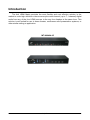
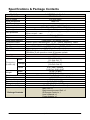
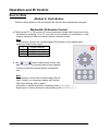
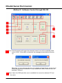
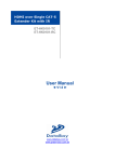
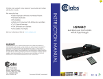
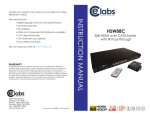
4x4 HDMI Matrix Switch MT-H00404-0C User Manual ◄ V1.1 ► www.databay.uk.com Introduction The 4x4 HDMI Matrix provides the most flexible and cost effective solution in the market to route high definition video sources plus multi-channel (up to 7.1 channel) digital audio from any of the four HDMI sources to the any four displays at the same time. This solution is well suited for use in home theater, conference room presentation systems, or other similar setting or application. MT-H00404-0C 2 / 15 Features z State-of-the-art Silicon Image (founder of HDMI) chipset embedded for upmost compatibility and reliability z HDMI 1.3c compliant z HDCP compliant z Allows any source to be displayed on multiple displays at the same time z Allows any HDMI display to view any HDMI source at any time z Supports 7.1 channel digital audio z Supports default HDMI EDID and learns the EDID of displays z The matrix master can switch every output channels to any HDMI inputs by push button, IR remote control, or RS-232 control z The cable length from input source to Matrix Switch plus Matrix Switch to output display is maximum 20 meters. 3 / 15 Specifications & Package Contents Model Name Model No. Role of usage HDMI compliance HDCP compliance Video bandwidth Video support Audio support ESD protection 4x4 HDMI Matrix Switch MT-H00404-0C True 4x4 matrix HDMI 1.3c Yes Single-Link 340MHz [6.75Gbps] 480i / 480p / 720p / 1080i / 1080p60 Surround sound (up to 7.1ch) or stereo digital audio [1] Human body model — ±15kV [air-gap discharge] & ±8kV [contact discharge] [2] Core chipset — ±8kV Input Output HDMI Input selection IR remote control HDMI connector RJ-45 connector RS-232 connector DIP switch 4 HDMI / 1x RS-232 4 HDMI Push button / IR remote / RS-232 Electro-optical characteristics: τ = 25° / Carrier frequency: 38kHz Type A [19-pin female] WE/SS 8P8C with 2 LED indicators [TMDS & DDC channels] DE-9 [9-pin D-sub female] [SW1~SW4] 2-pin for EDID, audio mode & safe mode [SW Main] 4-pin operation mode & firmware update Housing SPEC Material Metal 340 x 110 x 44mm Model [1’1.4”x4.3”x1.7”] Dimensions 545 x 230 x 110mm Package (L x W x H) [1’9.5”x9.1”x4.3”] Carton 570 x 580 x 260mm [1’10.5”x1’10.9”x10.2”] Model 1075g / [2.4lbs] Weight Package 2090g / [4.6lbs] Fixedness 1U rack-mount with ears and wall hanging holes Power supply 5V 6A DC Power consumption 20 Watts [max] Operation temperature 0~40°C [32~104°F] Storage temperature -20~60°C [-4~140°F] Relative humidity 20~90% RH [no condensation] Main Unit x 1 Rack-mounting ears (Set) x 1 IR Remote Control x 1 Package Contents User’s Manual x 1 Power Adapter x1 4 / 15 Panel Descriptions Front Panel 6 1. 2. 3. 4. 5. 6. 5 4 6 5 4 6 5 4 6 5 4 3 1 Power: Power indicator IR: IR receiver Input: Input source indicator HP1–HP4: Connection status indicator for each output channel Port1–Port4: Input source channels mapping LED for each output channel Port1 Select–Port4 Select: Push button for selecting input channels Rear Panel 13 2 11 12 10 9 8 9 8 7 7. 8. 9. 10. 11. HDMI OUT1–HDMI OUT4: HDMI outputs IN1–IN4: HDMI inputs SW1–SW4: DIP switch [see DIP Switch section in p.6] SW Main: DIP switches [see DIP Switch section in p.7] RS-232: RS-232 control port 12. 13. +5V DC: 5V DC power jack Power on/off switch 5 / 15 DIP Switch SW1-SW4 for EDID/Audio DIP Switch Position Pin#1 Pin#2 Video Audio OFF [©] Up to 1080p Stereo1 OFF [©] ON [ª] Up to 720p / 1080i Stereo ON [ª] OFF [©] Bypass4 Bypass4 ON [ª] ON [ª] Bypass Stereo OFF [©] Description Default Mode2 – Up to 1080p & stereo audio output for most HDTVs Safe Mode3 – Enforce the system output at 720p/1080i video and stereo audio for basic compatibility among HDTVs EDID Learning Mode5 – for learning EDID from the display while playing any received HDMI audio format EDID Learning & Stereo Mode5 – for learning EDID from the display while enforcing stereo output if any HDTV cannot play surround sound normally Note 1 If the HDTV shows video but without audio, please try to set audio mode to stereo. 2 Factory default of SW1-SW4: Pin#1-OFF [©] & Pin#2- OFF [©] for 1080p with stereo. 3 If you encounter any unsolved audio/video output problem during system installation, please turn any SW1-SW4 to Pin#1-OFF[©] & Pin#1-ON[ª], for safe mode to enforce the most compatible 720p stereo output for system check. However, the safe mode cannot be initiated if your HDMI source is set to enforce 1080p output. In this case, please reconfigure your HDMI source to all resolution output for troubleshooting. 4 Bypass means the matrix will maintain playing the original format of HDMI signals in video and perhaps audio. By setting at this mode, the users may encounter compatibility issue among different kinds of HDMI sources and displays. If you cannot get the audio and/or video output normally at the system installation, please change the DIP switch setting to default mode or even safe mode to verify the functionality of the device. 5 Set Pin#1 at ON[ª] first then connect the HDMI Input to HDTV through a HDMI cable. Wait for 20 seconds. The EDID learning procedure will be finished. If you want to learn the EDID from another HDTV, you must set Pin#1 at OFF[©] first and repeat this procedure. 6 / 15 SW Main for firmware update (for technical support only) DIP Switch Position Pin#1 Pin#2 Pin#3 Normal Operation OFF [©] OFF [©] ON [ª] 6 Mode Firmware Update ON [ª] ON [ª] OFF [©] 7 Mode 6 Pin#4 OFF [©] OFF [©] Note Factory default for SW Main: Pin#1-OFF [©], Pin#2-OFF[©], Pin#3-ON [ª], Pin#4-OFF[©]. PLEASE MAINTAIN THIS SETTING AT ANYTIME FOR REGULAR USE! 7 Sequence for firmware update [1]. Power off the MT-H00404-0C. [2]. Set the DIP switch position to Firmware Update Mode. [3]. Power on the MT-H00404-0C. [4]. Power off the MT-H00404-0C. [5]. Set the DIP switch position to Normal Operation Mode. [6]. Power on the MT-H00404-0C. 7 / 15 Hardware Installation MT-H00404-0C 1. 2. 3. 4. Connect all sources to HDMI Inputs on the 4x4 HDMI Matrix Connect all outputs to HDMI devices Connect the +5V 6A DC power supply to the 4x4 HDMI Matrix Power on the 4x4 HDMI Matrix MT-H00404-0C Use ET-HK0101-RC / ET-KH0101-RC for HDMI over CAT5 transmission Short distance: 15m(50ft) under Full HD (1080p), or 25m (80ft) under HD (720p/1080i) 1. Plug ET-KH0101-RC into HDMI output 2. Plug ET-KH0101-RC into HDTV 3. Use CAT-5e LAN cable to connect devices in between Long distance: 35m(115ft) under Full HD (1080p), or 55m (180ft) under HD (720p/1080i) 1. Plug ET-KH0101-RC into HDMI output 2. Plug ET-HK0101-RC into HDTV 3. Use CAT-5e LAN cable to connect devices in between 8 / 15 Operation and IR Control Source Side Method A: Push Button Push the switch button on the front panel, the source will be sequentially changed. Method B: IR Remote Control a. Please press F1 to F4 to enter IR control mode and decide which output port to be controlled by pressing F1 to F4, and wait a few seconds for audio/video of next channel coming out after the channel switch command is sent. Note If the setting is correct, the corresponding LED will flash. If not, please press output port select button again. F1 HDMI output #1 F2 HDMI output #2 F3 HDMI output #3 F4 HDMI output #4 b. Use or keys to select input source, and wait a few seconds for audio/video of next channel coming out after the channel switch command is sent. Note If the setting is correct, the corresponding LED will flash. If there is no response, please wait until the LED stops flashing, and try again. Left button to switch channels in ascending order (1, 2, 3, 4, 1, ...) Right button to switch channels in descending order (1, 4, 3, 2, 1, …) 9 / 15 RS-232 Serial Port Control Method C: Software Control through RS-232 1 Scan: Push this button will trigger the automatic search over all the available COM ports (1-255). If the matrix is detected, the message window below will show up. Otherwise, an error message shows up to indicate no legal device can be found. Notice that successful connection is only established if there exists at least one available COM port. 2 Open: Open the COM port after scan to establish the connection between PC and the matrix. 10 / 15 3 Close: Release the COM port after scan. 4 Quick Setup Buttons: Provide the fast setup between inputs and outputs of the matrix. “Default” button makes input 1, 2, 3, 4 mapped to output 1, 2, 3, 4 respectively. “Channel 1” makes all outputs see input-1, same for the remaining buttons. 5 Output Channel Setup: Click on this button, a quick selection table of inputs will show up. Users can therefore easily select the input video for each output. 6 Input Channel Setup: The button will bring up the setup window for the inputs as below. A Input Channel: Select the input channel to do bitmap and label change. B Bitmap Path: Select the figure for each channel. Notice that only pictures in BMP format are supported. C Description: Channel description. 11 / 15 RS-232 Commands RS-232 transmission Format Baud rate: 9600 Data bit: 8 Parity: None Set Command Command Code Data 0x08 0x4d 0x41 0x51 0x44 0x05 *0x01~0xff 0x0c 0x4d 0x41 0x51 0x44 Device_Id 0x02 port1 port2 port3 port4 Check SUM 0x31~0x2f Response ACK 0xaa 0x0c+…+port4 0xaa Description SET SET MT-H00404-0C Device ID Set MT-H00404-0C Source Mapping of Output Port Status Command Command Code Data 0x05 0x4d 0x4f 0x44 0x07 0x4d 0x41 0x53 0x57 0x04 0x08 0x4d 0x41 0x51 0x44 *0x01~0xFF 0x01 0x08 0x4d 0x41 0x51 0x44 *0x01~0xFF 0x04 Response Check SUM Get Status Description Check SUM Status 0xaa 0x06 0x4d Get Device Type 0x29 0x41 0x51 0x44 MT-H00404-0C 0xaa 0x3 0x43 0x04~0x02 Get Device ID 0x01~0xff 0xaa 0x06 port1 0x2e~0x 0x06 + Get Source Mapping port2 port3 2c port1~port4 of Output Port port4 0xaa 0x08 0x56 0x30~0x Software Version 0x33 0x2e 0x30 0x81 2e V.3.01a 0x31 0x61 0xe5 Check sum: Check sum = (Data value sum)%256 The check sum of response is not included 0xaa. 0x01 ~ 0xFF: This data is device ID. The Device ID saved in the device, if the device ID of the controlled device is 0xff, the device will ignore its own ID and carry out the commands. 12 / 15 Firmware Update Warning! There could be unexpected consequences resulted from inappropriate firmware update operation. Please do it with caution. 1. Please unzip the Matrix_Firmware_Update.zip into your designated folder. 2. Please turn off the power of the MATRIX and set DIP location of [SW Main] at Pin#1-ON(ª), Pin#2-ON(ª), Pin#3-OFF(©), & Pin#4-OFF(©). 3. Please execute the file Matrix_Firmware_Update.exe 4. In the pop-up window, at [Select Chip], please select W78E365. 5. In the pop-up window, at [Select File], please choose the BIN file in the designated folder, as shown in the picture. 6. In the pop-up window, please select the [File Format] to Binary. 13 / 15 7. Please make sure your PC has direct connection to the RS-232 port of the MATRIX, as shown in the picture (left), that in [Communication Setting] the onlne status should be “Wait to connect”. If the RS-232 connection is not firmly established, you will see the online status is “Disconnect.” If so, please check the RS-232 connection until the online status becomes “Wait to Connect.” 8. Please turn on the MATRIX. The firmware update process will automatically initiate. If nothing happens, please turn off and turn on the MATRIX again to initiate the automatic firmware update. 9. The firmware update process is successful if you see the [Information] window pops up to inform you that the process is complete. If you see the [Error] window pops up, please turn off the MATRIX and turn it on again. If necessary, please redo the whole sequences 1-9. 10. The message “Program: OK!” means the firmware update process is successful. If you see the [Error] window pops up after the message [Program: OK!], please ignore it. 11. Turn off MATRIX. Set DIP location of [SW Main] at Pin#1-OFF(©), Pin#2-OFF(©), Pin#3-ON(ª), & Pin#4-OFF(©). 12. Turn the MATRIX back on and return to normal operation. 14 / 15 Notice 1. If the DVI or HDMI device requires the EDID information, please use EDID Reader/Writer to retrieve and provide DVI/HDMI EDID information. 2. All HDMI over CAT5 transmission distances are measured using Belden 1583A CAT5e 125MHz LAN cable and ASTRODESIGN Video Signal Generator VG-859C. 3. The transmission length is largely affected by the type of LAN cables, the type of HDMI sources, and the type of HDMI display. The testing result shows solid LAN cables (usually in bulk cable 300m/1000ft form) can transmit a lot longer signals than stranded LAN cables (usually in patch cord form). Shielded STP cables are better suit than unshielded UTP cables. A solid UTP CAT5e cable shows longer transmission length than stranded STP CAT6 cable. For long extension users, solid LAN cables are your only choice. 4. EIA/TIA-568-B termination (T568B) for LAN cables is recommended for better performance. 5. To reduce the interference among the unshielded twisted pairs of wires in LAN cable, you can use shielded LAN cables to improve EMI problems, which is worsen in long transmission. 6. Because the quality of the LAN cables has the major effects in how long transmission distance will be made and how good is the received display, the actual transmission length is subject to your LAN cables. For resolution greater than 1080i or 1280x1024, a CAT6 cable is recommended. 7. If your HDMI display has multiple HDMI inputs, it is found that the first HDMI input [HDMI input #1] generally can produce better transmission performance among all HDMI inputs. Performance Guide for HDMI over LAN Cable Transmission Performance rating Wiring Shielding Unshielded Solid (UTP) Shielded (STP) Unshielded Stranded (UTP) Shielded (STP) Termination CAT5 Type of LAN cable CAT5e CAT6 Please use EIA/TIA-568-B termination (T568B) at any time 15 / 15