1
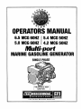
OPERATORS MANUAL
6.5 MCG 60HZ
5.0 MCG 60HZ
5.4 MCG 50HZ
4.2 MCG 50HZ
Multi-port
MARINE GASOLINE GENERATOR
SINGLE PHASE
CALIFORNIA PROPOSITION 65
WARNING
Exhaust gas from diesel and
gasoline engines (and some of
its constituents)· are known to
the State of California to cause
cancer, birth defects, and other
reproductive harm.
A WARNING:
Exhaust gasses contain Carbon Monoxide, an odorless and
colorless gas. Carbon Monoxide is poisonous and can cause
unconsciousness and death. Symptoms of Carbon Monoxide
exposure can include:
• Throbbing in Temples
•Dizziness
• Muscular Twitching
•Nausea
• Vomiting
•Headache
• Weakness and Sleepiness •Inability to Think Coherently
IF YOU OR ANYONE ELSE EXPERIENCE ANY OF THESE SYMPTOMS,
GET OUT INTO THE FRESH AIR IMMEDIATELY. If symptoms persist,
seek medical attention. Shut down the unit and do not restart
until it has been inspected and repaired. _
A WARNING DECAL is provided by WESTERBEKE and
should be fixed to a bulkhead near your engine or
generator.
WESTERBEKE also recommends installing CARBON
MONOXIDE DETECTORS in the living/sleeping
quarters of your vessel. They are cosl affective and
easily obtainable at your local marine store.
Gasoline with an ETHANOL content
higher than 10°/o (E10) is not allowed
and may void warranty.
~'~ •WESTERBEKE™
~
Engines & Generators
SAFETY INSTRUCTIONS
INTRODUCTION
Read this safety manual carefully. Most accidents are
caused by failure to follow fundamental rules and
precautions. Know when dangerous conditions exist and
take the necessary precautions to protect yourself, your
personne~ and your machinery.
The following safety instructions are in compliance with
the American Boat and Yacht Council (ABYC) standards.
PREVENT ELECTRIC SHOCK
A WARNING: Do not touch AC electrical connections
while engine is running. Lethal voltage is present at
these connections!
PREVENT BURNS - FIRE
A WARNING: Fire can cause injury or death!
•
Prevent flash fires. Do not smoke or permit flames or
sparks to occur near the fuel injector, fuel line, filter, fuel
pump, or other potential sources of spilled fuel or fuel
vapors. Use a suitable container to catch all fuel when
removing the fuel lines, injectors or fuel filters.
• . Do not operate with the Coast Guard Approved flame
arrester removed. Backfire can cause severe injury,, . ·
• Do not smoke or permit flames or sparks to occur near
the fuel system. Keep the COII).partment and the
engine/generator clean and free of debris to minimize the
chances of fire. Wipe up all spilled fuel and engine oil.
•
Be aware -
gasoline is highly flammable.
•
Do no~ operate this maehinery without electrical
enclosures and covers· in place.
•
Shut off electrical power before accessing electrical
equipment.
•
Use in~ulated mats whenever working on electrical
equipment.
•
Make sure your clothing and skin are dry, not damp
(particularly shoes) when handling electrical equipment.
•
•
Remove wristwatch and all jewelry when working-on
electrical equipment.
Do noit connect utility shore power to vessel's AC
circuits, except through a ship-to-shore double throw
transfer switch. Damage to vessel's AC generator may
result if this procedure is not followed.
Follow re-fueling safety instructions. Keep the vessel's
hatches closed when fueling. Open and ventilate cabin after
fueling. Check below for fumes/vapor before running the
blower. Run the blower per boat builders recommendations.
•
Electrical shock results from handling a charged
capacitor. Discharge capacitor by shorting terminals
together.
•
•
All fuel vapors are highly explosive. Use extreme care
when handling and storing fuels. Store fuel in a
well-ventilated area away from spark-producing
equipment and out of the reach of children.
Do not fill the fuel tank(s) while the generator is running.
Shut off the fuel service valve at the engine when servicing
the fuel system. Take care in catching any fuel that might
spill. DO NOT allow any smoking, open flames, or other
sources of fire near the fuel system or engine when
servicing. Ensure proper ventilation exists when servicing
the fuel system.
Do not alter or modify the fuel system.
•
•
PREVENT BURNS - EXPLOSION
A WARNING: Explosions from fuel vapors ca_n cause
injury or death/
PREVENT BURNS - HOT ENGINE
A WARNING: Do not touch hot engine parts or
exhaust system components. A running engine gets
very hot!
•
Always check the engine coolant level at the coolant
recovery tank.
A WARNING: Steam can cause injury or death!
•
In case of an engine overheat, allow the engine to cool
before touching the engine or checking the coolant.
•
·
·
•
•
Be sure all fuel supplies have a positive shutoff valve.
Be certain fuel line fittings are adequately tightened and
free of leaks.
•
Make sure a fire extinguisher is installed nearby and is
properly maintained. Be familiar with i'ts proper use.
Extinguishers rated ABC by the_NFPA are appropriate
for all applications encountered in this environment.
SAFETY INSTRUCTIONS
ACCIDENTAL STARTING
:A WARNING: Carbon monoxide (CO} Is a deadly gas!
A WARNING: Accidental starting can cause injury
or death!
•
Ensure that the exhaust system is adequate to expel gases
discharged from the engine. Check the exhaust system
regularly for leaks and mak:e sure the exhaust manifolds
are securely attacfled and no warping exists. Pay close
attention to the n1anifold, water injection elbow, and
exhaust pipe fittings.
• Be sure the unit and its surroundings are well ventilated.
• In addition to routine inspection of the exhaust system,
install a carbon monoxide detector. Consult your boat
. builder or dealer for installation of approved detectors.
• For additional information, refer to ABYC 'HT-22
(educational information on Carbon Monoxide).
• Thm OFF the DC breaker on the control panel or tum the
unit's battery selector switch to OFF before servicing the
engine.
• Disconnect the battery cables before servicing the engine/
generator. Remove the negative lead first and reconnect
it last.
• Make certain all personnel are clear of the engine before
starting.
• Make certain all covers, guards, and hatches are
re-installed before starting the engine.
BAMRY EXPLOSION
A WARNING: Carbon monoxide (CO} Is an Invisible
odorless gas. Inhalation produces nu-1/ke symptoms,
nausea or death!
A WARNING: Battery explosion can cause Injury
or death!
•
• Do not smoke or allow an open flame near the battery
being serviced. Lead acid batteries emit hydrogen, a
highly explosive gas, which can be ignited by electrical
arcing or by lit tobacco products. Shut off all electri~al
equipment in the vicinity to prevent electrical arcing
during servicing.
• Never connect the negative (-) battery cable to the
positive (+) connection terminal of the starter solenoid.
Do not test the battery condition by shorting the terminals
together. Sparks could ignite battery gases or fuel vapors.
Ventilate any compartment containing batteries to prevent
accumulation of explosive gases. To avoid sparks, do not
disturb the battery charger connections while the battery
is 'being charged.
• Avoid contacting the terminals with tools, etc., to prevent
burns or sparks that could cause an explosion. Remove
wristwatch, rings, and any other jewelry before handling
the battery.
• Always tum the battery charger off before disconnecting
the battery connections. Remove the negative lead first
and reconnect it last when disconnecting the battery.
•
•
Do not use copper tubing in exhaust systems. EXhaust
sulfur causes rapid deterioration of copper tubing
resulting in exhaust/water leakage.
Do not install exhaust outlet where exhaust can be drawn
through portholes, vents, or air conditioners. If the engine
exhaust discharge outlet is near the waterline. water could
enter the exhaust discharge outlet and close or restrict the
flow of exhaust. Avoid overloading the craft.
Carbon monoxide gas is present in exhaust fumes. Some
of the symptoms or signs of carbon monoxide inhalation
or poisoning are:
Vomiting
Muscular twitching
Dizziness
Intense headache
Throbbing in temples Weakness and sleepiness
AVOID MOVING PARTS
A
WARNING:.Rotatlng parts can cause Injury
or death!
•
BAnERYACID
A WARNING: Sulfuric acid In batteries can cause
Do not service the engine while it is running. If a
situation arises in which it is absolutely necessary to
make operating adjustments, use extreme c:are to avoid
touching moving parts and hot exhaust system
· ·
components.
severe InJury or death!
• When servicing the battery or checking the electrolyte
level, wear rubber gloves, a rubber apron, and eye
protection. Batteries contain sulfuric acid, which is
destructive. If it comes in contact with your skin, wash it
off at once with water. Acid may splash on the skin or
into the eyes inadvertently when removing electrolyte
caps.
Engines & Generators
ii
SAFETY INSTRUCTIONS
• Do not wear loose clothing or jewelry when servicing
equipment; tie back long hair and avoid wearing loose
jackets, shirts, sleeves, rings, necklaces or bracelets that
could be caught in moving parts.
• Make sure all attaching hardware is properly tightened.
Keep protective shields and guards in their respective
places at all times.
• Do not check fluid levels or the drive belt's tension while
the engine is operating.
• Oo not allow any swimming or activity around or near
the exhaust discharge opening for the generator while the
generator is operating. Carbon Monoxide poisoning or
death can occur.
ABYC, NFPA AND USCG PUBLICATIONS FOR
INSTALLING ENGINES AND GENERATORS
Read the following ABYC, NFPA and USCG publications
for safety codes and standards. Follow their recommendations when installing your engine.
ABYC (American Boat and Yacht Council)
"Standards and Technical Information Reports for Small
Craft"
Order from:
ABYC
613 Third Street, Suite 10
Annapolis, MD 21403
www.abycinc.org
NFPA (National Fire Protection Association)
"Fire Protection Standard for Motor Craft"
Order from:
NFPA
11 Tracy Drive
Avon Industrial Park
Avon, MA 02322
USCG (United States Co~st Guard)
"USCG 33CFR183"
Order from:
U.S. Government Printing Office
Washington, D.C. 20404
HAZARDOUS NOISE
A WARNING: High noise levels can cause hearing
loss!
• Never operate an engine without its muffler installed.
• Do not run the engine with the air intake (silencer) or
flame arrester removed.
• Do not run engines for long periods with their enclosures
open (when installed).
A WARNING: Do not work on machinery when you are
mentally or physically incapacitated by fatigue!
OPERATORS MANUAL
Many of the preceding safety tips and warnings are repeated
in your Operators Manual along with other cautions and
notes to highlight critical information. Read your manual
carefully, maintain your equipment, and follow all safety
procedures.
GASOLINE ENGINE AND GENERATOR INSTALLATIONS
Preparations to install a gasoline engine or generator should
begin with a thorough examination of the American Boat and
Yacht Council's (ABYC) standards. These standards are from
a combination of sources including the USCG and the NFPA.
Sections of the ABYC standards of particular interest are:
H-2 Ventilation for Boats using Gasoline
H-24 Gasoline Fuel Systems
P-1 Installation of Exhaust Systems
for Propulsion and Auxiliary Engines
P-4 Marine Inboard Engines and Transmissions
E-IIAC and DC Electrical Systems on Boats
All installations must comply with the Federal Code of
Regulations (FCR).
Engines & Generators
iii
INSTALLATION
When installing WESTERBEKE engines and generators it is important that strict
attention be paid to the following information:
CODES AND REGULATIONS
Strict federal regulations, ABYC guidelines, and safety codes must be complied with
when installing engines and generators in a marine environment.
SIPHON-BREAK
For installations where the exhaust manifold/water injected exhaust elbow is close to
or will be below the vessel's waterline, provisions must be made to install a siphonbreak in the raw water supply hose to the exhaust elbow. This hose must be looped a
minimum of 20" above the vessel's waterline. Failure to use a siphon-break when
the exhaust manifold injection port is at or below the load waterline will result in
raw water damage to the engine and possible flooding of the boat.
If you have any doubt about the position of the water-injected exhaust elbow relative
to the vessel's waterline under the vessel's various operating conditions, install a
siphon-break.
NOTE: A siphon-break requires periodic inspection and cleaning to ensure proper
operation. Failure to properly maintain a siphon-break can result in catastrophic
engine damage. Consult the siphon-break manufacturer for proper maintenance.
AVAILABLE FROM
YOUR WESTERBEKE
DEALER
SIPHON-BREAK WITH STAINLESS
LOOP
EXHAUST SYSTEM
The exhaust system's hose MUST be certified for marine use. Corrugated Marine
Exhaust Hose is recommended. The use of this type of hose allows for extreme bends
and turns without the need of additional fitting and clamps to accomplish these bends
and turns. In this regard, a single length of corrugated exhaust hose can be used. The
system MUST be designed to prevent the entry of water into the exhaust system
under any sea conditions and at any angle of vessels heel.
A detailed Marine Installation Manual covering gasoline and diesel,
engines and generators, is supplied with each unit. A pdf is available
to download from our website at www.westerbeke.com.
Engines & Generators
iv
CARBON MONOXIDE "CO"/LOW-CO GENERATORS
IMPORTANT INFORMATION
DESCRIPTION
In a closed space, such as the engine compartment, the boat,
or underneath a stem swim platform, concentrations will
potentially rise to the undiluted level emanating from the
exhaust system due to a lack of fresh air to dilute the exhaust
gas. Therefore, one should never rely on dilution of the
exhaust to provide a margin of safety.
Westerbeke Low-CO generators achieve reduction of CO
by precise control control of the engine's air/fuel ration
coupled with after treatment in a special catalyst. CO
emissions are not the same for every model because each
engine is different. Also, certain fuel system components are
comrnonized across several engine models being adequate
for some and extra-adequate for others, thus producing
different CO levels for different models.
Carbon monoxide "CO" is a component of engine exhaust. It
is a colorless, tasteless, odorless, lighter than air poisonous
gas that can kill you without any warning. CO poisoning is
one of the major safety risks associated with boating. It is a
threat that must not be underestimated.
Westerbeke Low-CO generators are designed to dramatically
reduce normal levels of CO in the engine exhaust.
Several standards for CO have been published, expressed in
parts per million "ppm" and hours of exposure:
Regulator
CO ppm
EPA
9
ACGIH
EPA
25
35
35
50
125
200
1200
NIOSH
OSHA
ACGIH
NIOSH
NIOSH
(IDLH)
Exposure Hours
8
8
The fuel system which accomplishes the required precise
air/fuel ratio control is comprised of many different
components: purchased sub-assemblies, machined castings,
sensors, electronics and others. Because of the extreme level
of CO reduction, any variability in the functioning of any
these components can and will cause variability of the CO
output.
1
8
8
0.5
0.0
0.0
CO concentration also varies with load. Usually, but not
always, the worst case CO concentration occurs at maximum
load.
1200 ppm is the so-called IDLH concentration ·
IMMEDIATELY DANGEROUS TO LIFE AND HEALTH.
INSPECTION
The catalyst is critical to optimizing CO levels. Any water
intrusion into the exhaust system will likely quickly
compromise the proper operation of the catalyst.
Westerbeke's exhaust system installation instructions must be
adhered to.
A city in California characterizes the effect of CO
concentration this way:
Parts per Million
25
Responses
Permissible exposure level, no
apparent toxic symptoms.
100
No poisoning for long period.
AUowable for several hours.
200
Should not be exposed above
this level for any period of
time. A possible mild frontal
headache in two to three hours.
NOTE: Water intrusion is not a product defect and is not covered under warranty, neither Westerbekes normal
product warranty nor the emissions specific warranty
mandated by various regulating authorities such as EPA
andCARB.
Maintenance of any components affecting the flow of air or
the flow of fuel to the engine is critically important, such as
fuel filters and air filters (if any).
Inspection of the catalyst at the prescribed intervals is
critically important. The exhaust elbow is removed by
loosening the metal clamp to provide a view of the output
surface of the catalyst. Any visual irregularity of the normal
flush, honeycomb appearance is most likely a result of water
intrusion. The cause of the irregularity must be identified and
addressed. If there is irregularity, the catalyst and gasket must
be replaced. Upon careful reassembly of the catalyst, exhaust
elbow gasket, and exhaust elbow, check for the presence of
CO while the engine is running. This must be performed with
a CO analyzer.
Even though the generator normally produces very low levels
of CO, an exhaust leak of untreated exhaust would be
extremely dangerous. For this reason it is extremely important to install a CO detector near the generator and to be sure
it is always turned on and functioning properly. If this detector sounds, do not tum it off, assuming it is a false signal.
You can not taste, smell, or otherwise detect CO. Leave the
detector on, tum off all engines and generators, evacuate the
boat leaving ports and hatches open, and seek professional
help.
As soon as CO leaves the exhaust outlet, the level is subject
to dilution in the open air. The closer a person is to the
exhaust outlet, the higher the concentration of CO.
v
CARBON MONOXIDE. "CO"/ LOW·CO GENERATORS
IMPORTANT INFORIVIATION
Whenever taking the time to verify proper CO concentration
from the exhaust with a CO analyzer, always take the
opportunity to use the analyzer to "sniff' around the engine
looking for CO from exhaust leaks. Pay close attention to the
connection ofthe cylinder head to the exhaust manifold, the
exhaust manifold to the water injected exhaust elbow, and all
subsequent downstream exhaust components and hoses.
Remember, exhaust gas that has not yet passed through the
catalyst is raw, untreated exhaust and is very high in CO
content.
Catalyst performance will degrade over time. As the
generator accumulates operating hours, CO concentrations
will increase. The catalyst must be replaced every 2,000
hours of engine operation.
Verification of satisfactory CO levels must be done
seasonally or each 1,000 hours (which ever occurs first).
Verification involves actual sampling of exhaust gas with an
appropriate CO analyzer.
·
There are two locations where exhaust gas can be sampled.
Dry, but hot, exhaust can be sampled at the plugged tapped
hole in the exhaust elbow intended for back pressure
measurements. Measurements at this location may not be
practical in all instances due to the high exhaust temperature,
temperature limits of the analyzer, safety concerns over ·
temperatures involved or the possibility of high levels of CO.
The other location. is the boat's exhaust outlet, which
contains entrained cooling water (except dry stack exhaust
systems). Only analyzers with probes should be used at this
loca~on and it is critical that the probe not ingest water.
Probe-type analyzers have an air pump drawing a gas sample
through the probe. As a result, they tend to ingest water when
it is present. Be sure to aim the probe downwards with the
opening pointed in the direction of the water flow and just
out of the flow. Position the analyzer as high as possible with
the tubing leading to the probe running continu~usly do_wnhill. Observe the usually translucent tubing between the
probe and the analyzer and be sure no,water is being
ingested. If any water is ingested into the analyzer, it must be
repaired or replaced and recalibrated.
Analyzers usually require periodic calibration. Follow the
instructions that come with the analyzer very carefully
regarding calibration.
The following are manufacturers that offer CO analyzers:
Extech, TIF; Testo, TSI, Bacharach, Fluke, Monoxor, Pyrite,
Zellwgwer Analytics, Industrial Scientific Corp, GFG, TPI,
Teledyne and others. Westerbeke recommends analyzers with
a probe connected to the analyzer by a length of transparent
tubing. They are slightly more expensive than those with the ·
sensor built into one end of the analyzer, but they allow you
to sample the exhaust coming out of the boat's exhaust outlet.
When measuring CO at the exhaust outlet be aware of the
ambient CO level by also measuring CO away from and
upwind of the exhaust outlet, especially in marinas. the CO
level.at the exhaust will be influenced upwards by the
ambient level.
Engines & Generators
vi
EMISSIONS
This genset meets the requirements of California's Exhaust
Emissions Standards as stated on the nameplate.
You should carefully review operator (Owner Installation
and other manuals and information you receive with your
genset. If you are unsure that the installation, use,
maintenance or service of your genset is authorized, you
should seek assistance from an approved WESTERBEKE
dealer.
California genset users may use the table below as an aid in
locating information related to the California Air Resources
Board requirements for emissions control.
California users of this genset should be aware that
unauthorized modifications or replacement of fuel, exhaust,
air intake, or speed control system components that affect
engine emissions are prohibited. Unauthorized modification,
removal or replacement of the engine label is prohibited.
Federal Emissions Compliance Period: The Federal
Emissions Compliance Period referred to on the nameplate
indicates the number of operating hours for which the engine
has been shown to meet Federal Emissions requirements.
Catagory C= 250 hrs, B=500 hrs, A =1000 hrs.
EMISSIONS CONTROL INFORMATION TABLE
Emissions Warranty Information
The California emissions control warranty statement is located in the same
packet, if information as this manual when the genset is shipped from the
factory.
Engine Fuel Requirements
The engine is certified to operate on unleaded gasoline. See FUEL
RECOMMENDATIONS.
Engine Valve Adjustment
See MAINTENANCE SCHEDULE.
Engine Ignition Timing
See MAINTENANCE SCHEDULE.
Engine Lubricating Oil Requirements
See ENGINE OIL RECOMMENDATIONS.
Engine Adjustments
Engine Emission Control System
ECU.
The engine emission control system consists of engine design and precision
manufacture.
Catalyst
See MAINTENANCE SCHEDULE.
Oxygen Sensor
See MAINTENANCE SCHEDULE.
Back Pressure
See MAINTENANCE SCHEDULE.
..
VII
TABLE OF CONTENTS
Battery Charging Circuit ...................................................... 19
Etlgine Troubleshooting .....................................................20
PC Monitoring..................................................."' ................22
Control Box Components .....................................................22
Generator Information ..........................................................23
Parts Identification .................................................................2
lntroduction ..............................................................................3
Fuel, Engine Oil and Engine Coolant.. ................................s
Preparations for Initial Start-Up .........................................6
Control Panel • Starting/Stopping Procedure .................... 7
Remote-Stop/Start Procedure ............................................. 8
Break-In Procedure (Daily Operation) .................................9
Safety Shutdown Sensors/Switches .................................. ! o
Maintenance Schedule ..................................................... 11
Fuel System ....................................................................... 13
AC Terminal Connections ............................................. 24
Windings Schematic ...................................................... 24
Shore Power Transfer Switch ...............................................25
Engine/Generator Wiring Diagrams (#55536) ....................26
Ignition System Components ......................................... 26
Control Box Components .............................................. 27
Fuel System Components .............................................. 28
Battery Charging Circuit.. .............................................. 28
Exhaust System Components ........................................ 29
Throttle Body Components ............................................ 29
ECU Components .......................................................... 30
Gasoline/Water Separator/Filter..................................... l3
Fuel Pump ...................................................................... 13
Fuel Filter ........................................................................ 13
Cooling System .................................................................. 14
Changing Coolant .......................................................... 14
Thermostat ...................................................................... 1S
Remote Panel Wiring Diagram .............................................31
DC Auxiliary Power Adapter ................................................31
MCG Generator Specifications .......................................... .32
Lay-Up and Recommissioning ..............................................33
Remote Oil Filter ...................................................................34
Tightening Torque Specifications .......................................35
Suggested Spare Parts .........................................................36
Zinc Anode ..................................................................... 15
Heat Exchanger .............................................................. 16
Raw Water Intake Strainer ............................................. l6
Raw Water Pump ........................................................... 1~
Changing the Impeller .;., .... ,.......................................... 16
Engine Lubricating Oil ....................................................... 17
Changing the Oil ........................................................... 17
Replacing the Filter ........................................................ 17
Engine Adjustments .......................................................:...... 18
Spark Plugs .................................................................... 18
Air Screen ...................................................................... 18
Oil Pressure .................................................................... 18
Engines & Generators
1
PARTS IDENTIFICATION
HARNESS TO ECU CONNECTIONS
CHARGER FUSE
CHARGER
SIPHON BREAK ---+1-'\1\-c-~
CONNECTION
EXHAUST
TEMPERATURE
SWITCH
AC CIRCUIT BREAKER
TEST PORT
EXHAUST BACK I'Kt::sutu:-
FRONT
LEFT
EXHAUST HOSE CONNECTION,
SIDE
THROTTLE BODY
ANODE
OIL FILL CAP
THERMOSTAT
DIPSTICK
CONTROL BOX
INJECTOR
HEAT
EXTERNAL ALARM
MOTOR
AIR SCREEN
IN-LINE FUEL FILTER
ELECTRIC FUEL LIFT PUMP
FUEL
MODULE
2
CONNECTION
GROUND
RIGHT SIDE
INTRODUCTION
MANUALS/SOFTWARE
-
This WESTERBEKE Generator is a product of
WESTERBEKE's long years of experience and advanced
technology. We take great pride in the superior durability and
dependable perfonnance of our engines and generators.
Thank you for selecting WESTERBEKE.
In order to get the full use and benefit from your generator, it
is important that you operate and maintain it correctly. This
manual is designed to help you do this. Please read this
manual carefully and observe all the safety precautions
throughout. Should your generator require servicing, contact
your nearest WESTERBEKE dealer for assistance.
This is your Operators Manual. Along with this manual there
is an Installation Manual and Parts lnfonnation. A service
Manual is available and can be ordered from your local
WESTERBEKEIUNIVERSAL dealer.
.
.
Westerbeke frequently updates manuals and software. Please
insure that you will have the latest infonnation by consulting
your WESTERBEKE representative or visit our website at
www.westerbeke.com
WARRANTY PROCEDURES
Your WESTERBEKE Warranty Statement is included in the,
product documentation package. There is a warranty .
registeration card you can fill out and mail to Westerbeke
Corporation or go to our website www. westerbeke.com and
register your product's warranty on line. You should receive a
customer warranty identification card in the mail within 60
days of registering. If you do not, please contact the factory
and have your product model number, serial number and in
service date available.
The generator serial
nwnber is stamped
on the top of the
generator no~r.sznf!.
Customer ldentific~tion Card
L"'f!V"IWESTERBEKE
I Engines & Generators
O!stomer ldenfification
WESTBRBEKE OWNER
MAlN~T
HOME'I'OWN, USA
Model
Fill in the information for your own reference.
Ser. #:
Expires
NOTE: Technical information is provided in our Manuals for
your reference and convenience. Westerbeke recommends
that your engine, generator or climate control system is
serviced and/or installed only by a qualified Westerbeke
distributor or dealer.
NOTES, CAUTIONS AND WARNINGS
As this manual takes you through the operating procedures,
maintenance schedules, and troubleshooting. Criticl:!l
infonnation will be highlighted by NOTES, CAuTIONS,
and WARNINGS. An explanation follows:
The 6.5/5.0 MCG Service Manual (#055748) is available as
a Pdf download at www.westerbeke.com. This Service
Manual can also be purchased from your WESTERBEKE
DEALER as a book.
NOTE: An operating procedure essential to note.
A CAUTION: Procedures, which if not strictly
observed, can result in the damage or destruction of your
engine.
A WARNING: Procedures, which if not properly
followed, can result In persona/Injury or loss of life.
Engines & Generators
3
INTRODUCTION
PROTECTING YOUR INVESTMENT
ORDERING PARTS
Care at the factory during assembly and thorough testing
have resulted in a WESTERBEKE generator capable of
many hours of dependable service. However, the
manufacturer cannot control how or where the generator is
installed in the vessel or the manner in which the unit is
operated and serviced in the field. This is up to the
buyer/owner-operator.
Whenever replacement/service parts are needed, always
provide the generator model number, engine serial number,
and generator serial number as they appear on the silver and
black name plate located on the generator end. You must
provide us with this information so we may properly identify
your generator set. In addition, include a complete part
description and part number for each part needed (see the
separately furnished Parts Catalog). Also insist upon
WESTERBEKE genuine parts because will fit or generic
parts are frequently not made to the same specifications as
original equipment.
NOTE: Six important steps to ensure long generator life:
• Proper installation.
• An efficient weU-designed exhaust system that includes
an anti-siphon break to prevent water from entering the
engine.
SPARES AND ACCESSORIES
Certain spares will be needed to support and maintain your
WESTERBEKE generator. Your local WESTERBEKE
dealer will assist you in preparing an inventory of spare parts.
• Changing the engine oil and oil filters as outlined in the
Maintenance Schedule.
Suggested Spares are shown in the last page of this manual.
For additional parts and accessories, contact your
WESTERBEKE DEALER.
• Proper maintenance of all engine and generator
components according to the Maintenance Schedule in
this manual.
INSTALLATION MANUAL
• Use clean, filtered unleaded fuel, maximum 10%
ethenol.
Publication #043268 provides detailed information for
installing generators.
• Winterize your engine according to the lAY-UP AND
RECOMMISSIONING section in this manual.
CARBON MONOXIDE DETECTOR
UNDERSTANDING THE GASOLINE ENGINE
WESTERBEKE recommends mounting a carbon monoxide
detector in the vessels living quarters. Carbon monoxide,
even in small amounts, is deadly.
The gasoline engine driving an AC generator is in many
ways similar to a gasoline automobile engine. The cylinders
are vertical in-line, and the engine's cylinder head has an
overhead camshaft which is belt driven. The engine utilizes a
solid-state distributor which is horizontally mounted and
camshaft-driven. The engine incorporates a pressure type
lubrication system and a fresh water-cooled engine block,
which is thermostatically controlled. To a large degree, the
generator's engine requires the same preventative maintenance that is required of a gasoline automobile engine. The
most important factors to the generator's longevity are proper
ventilation, maintenance of the fuel system, ignition system,
cooling system and the generator back-end.
The presence of carbon monoxide could indicate an exhaust
leak from the engine or generator or from the exhaust
elbow/exhaust hose or exhaust system.
If carbon monoxide is present, ventilate the area with clean
air and correct the problem immediately!
4
FUEL, ENGINE OIL AND ENGINE COOLANT
GASOLINE
ENGINE COOLANT
A CAUTION: Use unleaded 89 Octane gasoline or
=for
higher. Ethanol gasoline must not exceed E10 (10%).
Gasoline with higher percentages of Ethanol are not
use In these models and~
Care Of The Fuel Supply
J
~
Use only clean properly filtered fuel! The fit and tolerance of
some components in the unit's fuel system are very critical;
dirt particles which might pass through the filter can damage
these finely finished parts. It is important to buy clean fuel,
and keep it clean. The best fuel can be rendered
unsatisfactory by careless handling or improper storage
facilities. To assure that the fuel going into the tank for your
engine's daily use is clean and pure, the following practice is
advisable:
WESTERBEKE recommends a mixture of 50% antifreeze
and 50% distilled water. Distilled water is free from the
chemicals that can corrode internal engine surfaces.
The antifreeze performs double duty. It allows the engine
to run at proper temperatures by transferring heat away from
the engine to the coolant. It also lubricates and protects the
cooling circuit from rust and corrosion. Look for a good
quality antifreeze that contains Supplemental Cooling
Additives (SCAs') that keep the antifreeze chemically
balanced, crucial to long term protection.
The distilled water and antifreeze should ben pre-mixed
before being poured into the cooling circuit.
NOTE: Use the new environmentallyjriendly, long lasting,
antifreeze that is now available.
A proper 50/50 mixture as recommended will protect the
engine coolant to temperatures of -40"F.
COOLANT RECOVERY TANK
Purchase a well-known brand of fuel.
A coolant recovery tank kit is supplied with each generator.
The purpose of this recovery tank is to allow for engine
coolant expansion and contraction during engine operation,
without the loss of coolant and without introducing air into
the cooling system.
Install and regularly service a good, Coast Guard approved
metal bowl type filter/water separator between the fuel tank
and the engine.
ENGINE OIL
Use a good brand of engine oil with an API and SAE
designations as listed in the SPECIFICATION Section of
this manual.
Change the engine oil and filter after an initial 50 hours of
engine break-in operation. Then follow the oil and filter
change intervals as specified in the MAINTENANCE
SCHEDULE in this manual.
Westerbeke Corporation does not approve or disapprove
the use of synthetic oils. If synthetic oils are used, engine
break-in MUST be performed using conventional oil. Oil
change intervals must be as listed in the MAINTENANCE
SCHEDULE section in this manual and not to be extended
if synthetic oils are used.
NOTE: The information above supercedes all previous
statements regarding synthetic oil usage.
NOTE: This tank, with its short run of plastic hose, is best
located at or above the level of the engines exhaust
manifold.
5
PREPARATIONS FOR INITIAL START-UP
PRESTARTINSPECTION
• Visually examine the unit. Look for loose or missing
parts, disconnected wires, unattached hoses, and check
threaded connections. Search for any gasoline leaks.
Before starting your generator for the first time or after a prolonged layoff, check the following items:
• Check AC wiring for correct connections as specified in
the wiring diagrams.
• Check the engine oil level: add oil to maintain the level at
the full mark on the dipstick.
• Inspect exhaust system connections.
• Check the fuel supply and examine the fuel filter/separator
bowls for contaminants.
• Be sure no other generator or utility power is connected to
the load lines .
• Check the DC electrical system. Inspect wire connections
and battery cable connections.
• Confirm that systems with a neutral line are
properly grounded (or ungrounded) as the system requires,
and that generator neutral is properly connected to the
load neutral. In single phase systems an incomplete or
open neutral can supply the wrong line-to-neutral
voltage on unbalanced loads.
NOTE: The starting battery must be totally dedicated to the
generator and maintained by the generators DC charging
alternator and no other source.
• Check the coolant level in both the plastic recovery tank
and at the manifold.
• Make certain the raw water thru-hull is open.
NOTE: During the initial filling of the cooling system, the
air bleed petcock on the manifold should be opened to
purge air from the engine block. Once cooled, free of air
bubbles, flows from the petcock - close the petcock.
A
CAUTION: When starting the generator, it is
recommended that all AC loads, especially large
motors, be switched OFF until the engine has come
up to speed and, in cold climates, starts to warm up.
This precaution will prevent damage caused by
unanticipated operation of the AC machinery and will
prevent a cold engine from stalling.
After shutdown and after the engine has cooled, the
coolant from the recovery tank will be drawn into the
engines cooling system to replace the purged air.
Before subsequent operation of the generator; the engines
manifold should be topped off, and the coolant recovery
tank may need to have coolant added. Do not overfill as.
coolant loss will occur.
AIR BLEED
PETCOCK
MAX. FULL
COOLANT
RECOVERY TANK
MANIFOLD
PRESSURE
CAP
COOLANT
Fill
THERMOSTAT
HOUSING
ROCKER COVER
RAW WATER DRAIN
HEAT EXCHANGER
FRESH WATER
DRAIN
OIL DRAIN
HOSE
Engine.t;_ & Genera~ors
6
CONTROL PANEL· START/STOP PROCEDURE
TO START: (DC CIRCUIT BREAKER ON)
DC CIRCUIT BREAKER
Simply press the rocker switch to the ~t~ position ~d r~lease
(the switch will revert to its center position) the en1pne w~l
START electronically. A GREEN LED on the switch Will
indicate the engine is running.
NOTE: There is a few second delay while the ECU self-tests
before the start switch responds.
GREEN LED
THIS LED ILLUMINATES FAINTLY
WHEN THE ENGINE IS NOT
RUNNING (DC CIRCUIT
BREAKER ON).
TO STOP
Press the rocker switch to the STOP position and release.
The GREEN LED will go out indicating the engine has
shut down.
CONTROL PANEL • OPERATING INSTRUCTIONS
Failure to Start
CONTROL PANEL: FUSE
BAMP
The start cycle will automatically terminate after 6-8 seconds
of cranking. Three crank cycles can be attempted before the
ECU initiates a SPEED fault and prevents further crank cycle
attempts.Investigate the cause ofthis no-start, correct it and
reset the ECU.
lED FAUlT
INDICATOR liGHTS
A CAUTION: Prolonged cranking can result in the
DC CIRCUIT BREAKER
exhaust filling with water and the water backing into
the engine. This could cause catastrophic damage to
your generator/engine.
TURN OFF WHEN
PERFORMING
.MAINTENANCE TO
PREVENT ACCIDENTAL
STARTING
The LED fault shut-down display has six LED light
combinations that indicate to the operator the cause of the
engines automatic shut-down. The LED displays are: CHECK
ENGINE, OIL PRESSURE, ENGINE TEMPERATURE,
EXTERNAL ALARM, EXHAUST TEMPERATURE and
SPEED (flashes).
Should the generator shut down from one of these faults, the fault
LED will remain illuminated. To reset the LED, the DC breaker
on the control box must be turned OFF and then back ON.
GENERATOR CONTROL PANEL
The start/stop rocker switch is the only functional component
on the generator control panel used to start and stop the
generator.
NOTE: The CHECK ENGINE LIGHT indicates a possible
emissions control problem. Immediate action should be taken
to troubleshoot and correct this problem.
The start/stop rocker switch is a three position switch with
momentary contacts in the (START) and (STOP) position and
a stationary contact in the center (NORMAL). This
position allows the generator to run once started and also
enables the remote start/stop panel(s) to control the start/stop
functions of the generator.
The Ext. Alarm indicates a faulty fire suppression circuit. By-pass
the circuit to determine the fault (the fire suppression circuit must
be closed when the circuit is running).
The 8 Amp Fuse protects the Control Panel from High
Amperage or Short Circuit.
The (START) position starts the generator and once released
reverts to the center position. The (STOP) position stops the
engine in normal operation as well as in an emergency
situation. This position is also used to prime the fuel system
when necessary.
The 15 Amp DC Circuit Breaker protects the Kl, K2, K3
relays (closed circuit) ftom high amperage or short circuit.
Sometimes after servicing the fuel system or changing the fuel
filter air can accumulate in the fuel lines or the fuel module
and ~revent starting. Schrader valves located on the high pressure pump module and the fuel rail are used to remove this .
trapped air. Refer to the BLEEDING THE FUEL SYSTEM m
YOUR SERVICE MANUAL.
7
REMOTE STOP/START PANELS
DESCRIPTION
Two remote start/stop panels are available that allow for the
engine/generator to be contolled from any location on the
boat.
The remote panels connect to the main panel using a 15' or
30' wiring haness (or a combined length of 45'). Once
installed, the engine/generator can be started and stopped
from either the remote or the main panel.
4"
(101.6
mm)
REMOTE START/STOP PANEL (with LED Fault Display)
The components on the panel are:
1. A three position start/stop rocker switch.
2. A green LED run indicator light on the rocker switch.
3. A four position LED fault shutdown display.
The start/stop rocker switch functions the same as the
start/stop rocker switch on the generator's control panel
as previously explained.
~----4" (101.6mm) -.-----;)oiO>II
The green LED run indicator light on the rocker switch will
illuminate when the start circuit is energized. It will go dim
as the engine cranks and will brighten as the engine starts,
indicating the generator is running.
The LED fault shutdown display has six separate LED
combinations that indicate to the operator the cause of the
engine's automatic shutdown. The LED displays are: Check
Engine, Oil Pressure, Engine Temperature, External Alarm,
Exhaust Temperature, and Speed (Overspeed -LEDs and
Underspeed-LEDs) flashing.
Should the generator shutdown from one of these faults, the
fault LED will remain illuminated. To reset the LED, the
panel DC breaker must be cycled OFF then ON.
PART N0.055345
NOTE: For connecting these remote panels, refer to the
Wiring Diagram section in this manual.
Engines & Generators
8
3.19 (81.03mm)
BREAK-IN PROCEDURE/THE DAILY OPERATION
BREAK-IN PROCEDURE
CHECK LIST
After the generator has been started, check for proper
operation and then allow the generator to warm up a few
minutes before applying a load .. Run the generator between
20% and 60% of full-load for the first 10 hours.
Follow this check list each day before starting your generator.
• Record the hourrneter reading in your log (engine hours
relate to the maintenance schedule).
• Visually inspect the generator for fuel, oil, or water leaks.
A CAUTION: Do not attempt to break-in your
• Check the oil level (dipstick).
generator by running without a load.
• Check the coolant level in the coolant recovery tank.
After the first 10 hours of the generators operation, the load
can be increased to the full-load rated output, then
periodically vary the load.
Avoid overload at all times. An overload is signaled by
reduced output voltage and/or frequency. MCG models will
illuminate a warning LED when the generator is overloaded.
Monitor the current being drawn from the generator and keep
it within the generators rating.
• Check your fuel supply.
NOTE: Be aware of motor starting loads and the high current
This condition should lessen as normal operating
temperature is reached and loads are applied.
• Check drive belts for proper tension.
• Check for abnormal noise such as knocking, vibration and
blow-back sounds.
• Inspect the exhaust system.
NOTE: Some unstable running may occur in a cold engine.
drawn required for starting motors. The starting amperage
drawn can be 3 to 5 times normal running amperage. See
GENERATOR INFORMATION in this manual.
A CAUTION: Do not operate the generator for long
periods of time without a load being placed on the
generator.
9
SAFETY SHUTDOWN SWITCHES
SENSORS AND SENDERS
DESCRIPTION
EXHAUST TEMPERATURE SWITCH
The engine/generator is protected by switches and sensors
that send signals to the ECU that it interprets as a fault and
automatically shuts down the generator's engine. When
an automatic shutdown occurs, one of the control panel fault
LED lights will illuminate indicating what fault caused the
engine to shutdown. This LED will stay illuminated. To .
correct the fault, refer to ENGINE TROUBLESHOOTING in
this manual. Do not attempt to re-start the generator
before correcting the fault.
A temperature switch is mounted on the exhaust elbow to
monitor the temperature of the exhaust coolant and gases.
Should the switch sense an excessive exhaust temperature,
the ECU witt shut the generator down and the exhaust
temperature LED wilt illuminate on the control panel.
SPEED SENSOR (CRANKSHAFT)
A speed sensor is mounted on a bracket at the front of the
engine and positioned to monitor crankshaft rotation. It sends
a voltage signal to the ECU that is interpreted.as engine
speed. If a speed threshold is reached, either overspeed or
underspeed, the ECU wilt shut the generator down. If both
speed LED'S are illuminated, it indicates overspeed. If both
LED'S are flashing, it indicates underspeed.
EXHAUST
TEMPERATURE
SWITCH
EXHAUST
COOLANT TEMPERATURE SENSOR
This sensor is located on the underside of the intake manifold
to monitor the engines coolant temperature. The sensor is
sending DC voltage to the ECU that interprets this as engine
coolant temperature. Should the temperature reach an overheat threshold, the ECU will shut the engine down and will
illuminate the engine temperature fault LED light on the control panel.
OIL PRESSURE SWITCH
An oil pressure switch is located on the right side of the oil
filter mounting bracket. This is a normally open contact
switch. It functions with the time relay circuit to ensure DC
voltage to the circuit is terminated when the unit shuts down.
OIL GALLERY
~)
DC CIRCUIT BREAKER
The engines electrical system is protected
by a 15 amp manual reset circuit breaker.
An electrical overload in the wiring harness
or the instrument panel will trip the breaker
and shut down the engine/generator. Should
this occur, inspect and repair the problem.
Then reset the breaker and re-start the engine.
An oil pressure sender (to the left of the oil filter) sends DC
voltage to the ECU that it interprets as oil pressure. Should
this voltage fall below a certain level, the ECU will shut the
generator down and illuminate the low oil pressure LED.
Should this occur, refer to ENGINE TROUBLESHOOTING
in this manual.
FUSE PROTECTION
Three fuses protect the engine's DC electrical system. A 30
amp spade type fuse in a holder adjacent to the starter motor.
An 8 amp fuse and 30 amp buss type mounted on the control
box.
Engines & Generators
10
MAINTENANCE SCHEDULE
A
WARNING: Never attempt to perform any service while the engine is running. Wear the proper safety equipment such as goggles
and gloves, and use the correct tools for each job. When servicing/replacing DC components, turn off the DC circuit breaker on the
control panel, or turn off the battery switch.
SCHEDULED MAINTENANCE
EXPLANATION OF SCHEDULED MAINTENANCE
I
DAILY CHECK BEFORE START-UP
Coolant Level
Check at recovery tank, if empty, check at manifold. Add coolant if needed.
Engine Oil Level
Oil level should indicate between MAX and LOW on dipstick. Do not overfill!
Fuel/Water Separator (owner installed)
Check for water and dirt in fuel. Drain filter if necessary. Replace filter every 250 operating
hours or once a year.
Fuel Supply
Fresh unleaded gasoline with an octane rating of 89 or higher. Lower octane will affect
engine performance. 10% ethanol maximum.
*Visual Inspection of Engine
Check for fuel, oil and water and exhaust leaks. Check that the water injected exhaust elbow
securing v-clamp is tight. Insure there are no exhaust leaks around the elbow. Inspect wiring
and electrical connections. Look for loose bolts/hardware and possible corrosion.
I INITIAL 50 HOURS OF OPERATION
*Spark Plugs
Clean/re-gap.
Engine Oil and Filter
Initial engine oil and filter change at 50 hours, then change both every 100 hours.
*Exhaust System
Initial check at 50 hours, then every 250 hours or once a year. Carefully inspect for leaks.
Check that the exhaust hoses are properly attached and that the securing clamps are tight.
Check the integrity/mounting security of the water injected exhaust elbow.
*Air Screen/Flame Arrestor
Remove, clean and re-install screen pack. Inspect rubber sealing ring and replace if
necessary, then once a year.
*Valve Adjustment
Check adjustment of valves. Check again at 500 hours.
*Inlet Fuel Filter
Initial change, then every 250 hours or once a year.
*Fuel Filter and "0" Rings
Initial change, then every 250 hours or once a year.
I EVERY 50 OPERATING HOURS OR MONTHLY
*Drive Belts
(Fresh Water/Raw Water Pumps)
Inspect for proper tension (3/8" to 1/2" deflection) and adjust if needed. Check belt
for slipping, cracking and wear. Adjust tension or replace as needed. Replace cover.
Starting Batteries
Check electrolyte levels Make sure cables and connections are in good order. Clean
off corrosion if needed. Apply petroleum jelly to terminals for corrosion protection.
Electric Fuel Pump
Inspect for leaks, ensure fuel and electrical connections are clean and tight.
Zinc Anode
Inspect and clean zinc anode. Replace if necessary. Note the condition, then determine
your own inspection schedule.
I EVERY 100 OPERATING HOURS OR YEARLY
Engine Oil and Filter
Change engine oil and filter.
*Air Screen/Flame Arrestor
Remove, clean and re-install screen pack. Inspect rubber sealing ring and replace if
necessary.
*WESTERBEKE recommends this service be performed by a knowledgeable mechanic.
Engines & Generators
11
MAINTENANCE SCHEDULE
NOTE: Use the engine hourmeter to log your engine hours or record your engine hours running time.
SCHEDULED MAINTENANCE
EXPLANATION OF SCHEDULED MAINTENANCE
IEVERY 250 OPERATING HOURS OR YEARLY
*Exhaust Elbow/Exhaust System
Check the structual integrity of the water injected exhaust elbow casting. Check the integrity
of the exhaust system attached to the elbow. All hose connections should be secure. No
chafing. No exhaust leaks. Hoses and muffler are in good serviceable condition.
NOTE: An exhaust leak will cause exposure to carbon monoxide!
*Fuel Filter and 0-Rings
Remove and replace fuel filter and all sealing 0-rings.
*Inlet Fuel Filter
Remove and replace inlet fuel filter.
*Generator
Check that AC connections are clean and secure. Ensure wires have no chafing.
See GENERATOR INFORMATION.
Engine hoses should be firm and tight. Replace if hoses become spongy, brittle or
delaminated. Check and tighten all hose clamps as needed.
Check vibration isolators, brackets and mounting hardware. Replace as needed.
*Hoses
Vibration Isolators/Engine Mounts
*Heat Exchanger
Open heat exchanger end cap(s) and clean out debris.
Replace gasket and 0-rings if needed.
IEVERY 500 OPERATING HOURS OR YEARLY
*Raw Water Pump
Remove the pump cover and inspect the pump assembly for wear, especially cam and wear
plates. Replace the impeller and gasket. Lubricate the impeller when re-assembling.
*Exhaust System Catalyst
Inspect for proper operation. Replace at 2000 operating hours.
IEVERY 500 OPERATING HOURS OR EVERY TWO YEARS
*Ignition System
Inspect for deterioration. Test resistance.
*Coolant System
Drain, flush and re-fill the cooling system with appropriate antifreeze mix. Replace the
thermostat and coolant pressure cap.
*Valve Clearances
Adjust valves. (Incorrect valve clearance will result in poor engine performance.)
*Starter Motor
Check solenoid and motor for corrosion. Remove and lubricate. Clean and lubricate the starter
motor pinion drive
EVERY 1000 OPERATING HOURS OR OR EVERY FIVE YEARS
*Engine Timing Belt
Remove and replace the timing belt. NOTE: Failure to replace the timing belt at the
recommended interval could result in timing belt failure resulting in major damage
to the engine.
*Heat Exchanger
Remove the heat exchanger for professional cleaning and pressure testing.
*Diverter Valve
Remove and replace.
I
EVERY 2000 OPERATING HOURS
*Oxygen Sensor
Remove and replace exhaust oxygen sensor.
*Catalyst
Remove and replace exhaust catalyst.
A WARNING: Never attempt to perform any service while the engine is running. Wear the proper safety equipment
such as goggles and gloves, and use the correct tools for each job. When servicing/replacing DC components, turn off
the DC circuit breaker on the control panel.
*WESTERBEKE recommends this service be performed by a knowledgeable mechanic.
The 6.5/5,0 MCG Service Manual (#055748) is available as
a Pdf download at www. westerbeke.com. This Service
Manual can also be purchased from your WESTERBEKE
DEALER as a book.
Enaines & Generators
12
FUEL SYSTEM
--·
FUEL SYSTEM COMPONENTS
..
--·-·:~-~~~
~- :~~----~CHRADER
. --:
FUEL RAIL
VALVE
Incoming fuel (from the owner installed Gasoline Water
Separator/Filter) is pumped thru the Inlet Fuel Filter into the
Fuel Module by the Electric Fuel Pump. The fuel is cooled
as it circulates through the Fuel Module and then is pumped by
the Electric Fuel Pump to the High Pressure Pump Module
and to the Secondary Fuel Filter. The fuel passes to the Fuel
Rail and is delivered (under pressure) to the Fuel Injectors.
I
I
I
+
I
Ir
)
I
_A:·---
FUEL FILTER
FUEL
IOILTER
INCOMING FUEL
GASOLINE/WATER SEPARATOR AND FILTER
ENGINE FUEL FILTER
Periodically check the fuel connections and the bowl for
leakage. Replace the filter element after the first 50 hours
then follow the MAINTENANCE SCHEDULE.
A primary fuel filter of the water separating type must be
installed between the fuel tank and the engine to remove
water and other contaminants from the fuel before they can
be carried to the fuel system on the engine.
Most installers include a type of filter/water separator with
the genemtor installation package as they are aware of the
problems that contaminants in the fuel can cause.
Changing the Engine Mounted Filter Element
1. Shut the fuel supply to the generator off.
2. Bleed the fuel system to reduce the fuel pressure to zero.
Refer to BLEEDING THE FUEL SYSTEM.
3. Unscrew the fuel bowl from the housing and pull the
filter element down and off. Use care to catch any fuel
that may be present.
These gasoline filters must have metal bowls (not seethrough) to meet U.S. Coast Guard requirements. The metal
bowls have drain valves to use when checking the water and
contaminants.
··
4. Replace the two sealing "0" rings. Install the new filter
element and thread on the fuel bowl then tighten by hand
5. Open the fuel supply to the generator and start the unit.
Ensure that there are no leaks.
6. Bleed the fuel system again to remove trapped air from
the system. Refer to BLEEDING THE FUEL SYSTEM.
OWNER INSTALLED
FUEL WATER
SEPARATOR
PN.049602
BLEEDING THE FUEL SYSTEM
The engine's fuel system should be bled of air at the initial
commissioning of the unit, each time the fuel system is
serviced and once a season to ensure any air that may have
accumulated in the system is removed. Bleeding instructions
are found in the model's SERVICE MANUAL.
FUEL PUMP
Periodically check the fuel connections to and out of the
pump and make sure that no leakage is present and that the
fittings are tight and secure. The engine mounted fuel pump
is maintenance free.
13
COOLING SYSTEM
FRESH WATER COOLING CIRCUIT
Refilling the Coolant
An antifreeze mixture is pumped through the engine by a belt
driven circulating pump, absorbing heat from the engine. The
coolant then passes through the thermostat, into the heat
exchanger, then into the jacketed exhaust manifold into the
suction side of the circulating pump and then through the
engine.
After re-installing the coolant drain plugs, open the air bleed
petcock on the water jacketed exhaust manifold and slowly
pour new pre-mixed coolant into the open filler neck until
coolant is visable in the filler neck.
Start the engine and monitor coolant in the filler neck and
add as needed. Check the air bleed petcock and when coolant
flows from the petcock, close it.
Allow the engine to run and monitor coolant in the filler neck
and add as needed. When the coolant level is stable, fill to
the brim and install the pressure cap.
Remove the cap on the coolant recovery tank and fill with
coolant mix to halfway between LOW and MAX and replace
the cap. Run the engine and observe the coolant expansion
flow into the recovery tank.
After checking for leaks, stop the engine and allow it to cool.
Coolant should draw back into the cooling system as the
engine cools down. Add coolant to the recovery tank if
needed and make certain the coolant is topped off at the
pressure cap. Clean up any spilled coolant.
When the engine is started cold, external coolant flow is
prevented by the closed thermostat (although some coolant
flow is bypassed around the thermostat to prevent the exhaust
manifold from overheating). As the engine warms up, the
thermostat gradually opens, allowing full flow of the engine's
coolant to flow unrestricted to the external portion.of the
cooling system.
A CAUTION: Proper cooling system maintenance is
critical; a substantial number of engine failurbs can be
traced back to cooling system corrosion.
CHANGING COOLANT
The engine's coolant must be changed according to the
MAINTENANCE SCHEDULE. If the coolant is allowed to
become contaminated, it can lead to overheating problems.
Drain the engine coolant by removing the block drain adjacent to the oil filter, remove the in-board drain plug on the
heat exchanger and remove the pressure cap from the water
jacketed exhaust manifold.
MAKE CERTAIN THESE
PASSAGES ARE KEPT CLEAR
A CAUTION: The engine must be allowed to cool ·
down before attempting these procedures. Not only is
the surface of the engine hot but coolant temperatures
can be at 190' F.
COOLANT ReTRACTION
NOTE: Periodically check the condition of the pressure cap.
Ensure that lhe upper and lower rubber seals are in good
condition and check that the vacuum valve opens and closes
tightly. Carry a spare cap.
COOLANT
DRAIN
COOLANT DRAIN PLUG
LOCATED JUST BELOW
THE INTAKE MANIFOLD
14
COOLING SYSTEM
HEAT EXCHANGER
If the zinc pencil needs replacement, hold the hex boss into
which the zinc pencil is threaded with a wrench while
loosening the anode with another wrench. This prevents the
hex boss from possibly tearing off the exchanger shell. After
removing the zinc, note the condition of it. If the zinc is in
poor condition, there are probably zinc flakes within the
exchanger. Remove the end of the heat exchanger and clean
the inside of all zinc debris. Always have a spare heat
exchanger end gasket in case the present one becomes
damaged when removing the end cover. Replace the gasket
(refer to your engine model's heat exchanger end gasket part
number), o-ring, cover, and install a new zinc anode.
Cool raw water flows through the inner tubes of the heat
exchanger. As the engine coolant passes around these tubes,
the heat of the internal engine is conducted to the raw water
which is then pumped into the exhaust system and
discharged. The engine coolant (now cooled) flows back
through the engine and the cycle repeats itself.
The engine coolant and raw water are independent of each
other; this keeps the engine's water passages clean from the
harmful deposits found in raw water.
.
~TO SIPHON BREAK
AND EXHAUST
NOTE: The threads of the zinc anodes are pipe threads and do
not require sealant. Sealant should not be used as it may
insulate the zinc from the metal of the heat exchanger
housing preventing electrolysis action on the zinc.
THERMOSTAT
The thermostate controls the coolant temperature as· the
coolant continuously flows through the closed cooling circuit.
When the engine is first started, the closed thermostat
prevents coolant from flowing (some coolant is by-passed
around the thermostat to prevent the exhaust manifold from
overheating). As the engine warms up, the thermostat
gradually opens. The thermostat is accessible and can be
checked, cleaned, or replaced easily. Carry a spare thermostat
and gasket.
If you suspect a faulty thermostat, place it in a pan of water
and bring to a boif A working thermostate should open about 112".
TO COOLANT
RECOVERY TANK
lvHeat Exchanger Service
Remove, clean and pressure test the engine's heat exchanger
according to the interval listed in the Maintenence Schedule.
(A local automotive radiator shop should be able to clean and
test the heat exchanger.)
NOTE: Operating in silty and/or tropical waters may require
that a heat exchanger cleaning be peiformed more often.
ZINC ANODE
GASKET
A zinc anode (or pencil) is located in the raw water cooling
circuit within the heat exchanger. The purpose of the zinc
anode is to sacrifice itself to electrolysis action taking place
in the raw water cooling circuit, thereby reducing the effects
of electrolysis on other components of the system. The
condition of the zinc anode should be checked monthly and
the anode cleaned or replaced as required. Spare anodes
should be c;arried on board.
ZINC
~DOES
1! I
NEW
REPLACE
CLEAN & REUSE
~~~WESTERSEKE
Engines & Generators
15
COOLING SYSTEM
RAW WATER INTAKE STRAINER
NOTE: Always install the strainer at or below the waterline so
the strainer will always be self-priming.
A clean raw water intake strainer is a vital component of the
engine's cooling system. Include a visual inspection of this
strainer when making your periodic engine check. The water
in the glass should be clear.
Perform the following maintenance after every 100 hours of
operation:
1. Close the raw water seacock.
If the engine temperature warning light LED illuminates, the
cause may be that silt, leaves or grass may have been caught
up in the strainer, slowing the flow of raw water through the
cooling system.
TYPICAL RAW WATER INTAKE STRAINER
(OWNER INSTALLED)
INCOMING
RAW WATER
2. Remove and clean the strainer filter.
3. Clean the glass.
4. Replace the washer if necessary.
INSPECT AND
CLEAN EVERY
toO HOURS
SEACOCK
5. Reassemble and install the strainer.
6. Open the seacock.
t
7. Run the engine and check for leaks.
NOTE: The external thru-hull opening should be of the flush
NOTE: Also follow the above procedure after having run hard
type with a clear opening. No perforated or slot type external
opening. Let all the filtering be accomplished on the inside of
the hull where there is easy access to t~e strainer.
aground.
RAW WATER PUMP
Changing the Raw Water Pump Impeller
The raw water pump is a self-priming, rotary pump with a
non-ferrous housing and a Neoprene impeller. The impeller
has flexible blades which wipe against a curved cam plate
within the impeller housing, producing the pumping action.
Never allow the pump to run dry. There should always be
a spare impeller and impeller cover gasket aboard (an
impeller kit). Raw water pump impeller failures occur when
raw water is not present during engine operation. Such
failures are not warrantable, and operators are cautioned to
make sure raw water flow is present at start-up. The raw
water pump should be inspected periodically for broken or
tom impeller blades. See MAINTENANCE SCHEDULE.
Close the raw water intake valve. Remove the pump cover
and, using an impeller puller, screw drivers, or pliers,
carefully pry the impeller out of the pump. Install the new
impeller and gasket. Move the blades to conform to the
curved cam plate and push the impeller into the pumps housing. When assembling, apply a thin coating of lubricant to
the impeller and gasket. Open the raw water intake valve.
NOTE: Should a failure occur with the pumps internal parts
(seals and bearings), it may be more cost efficient to
purchase a new pump and rebuild the original pump as
a spare.
NOTE: Never allow the. pump to run dry. Even a short period
NOTE: Should a failure occur with the pumps internal parts
(seals and bearings), it may be more cost efficient to
purchase a new pump and rebuild the original pump as
a spare.
NOTE: If any of the vanes have broken off the impeller they
must be found to prevent blockage in the cooling circuit.
They often can be found in the heat exchanger.
of dry nmning may destroy the impeller.
IMPELLER
INSPECTION: CHECK AT THE BASE OF
EACH BLADE BY BENDING VIGOROUSLY.
REPLACE THE IMPELLER IF THERE
ARE ANY CRACKS.
WHEN INSTALLING: TAKE CARE TO ALIGN
THE IMPELLER KEYWAY WITH THE SHAFT
KEY. FOLD THE IMPELLER BLADES IN
EITHER DIRECTION (THEY WILL TURN IN
THE CORRECT POSITION WHEN THE
IMPELLER STARTS TO ROTATE).
RAW WATER
PUMP
PN 042026
WHEN ASSEMBLING: APPLY A THIN COAT OF
GLYCERIN TO THE INSIDE OF THE COVER, THE
COVER 0-RING, AND THE IMPELLER
Engines & Generators
16
ENGINE LUBRICATING OIL
APPLY A THIN COAT OF CLEAN OIL TO THE
FILTER GASKET WHEN INSTALLING. AFTER THE
FILTER CONTACTS THE BASE TIGHTEN FIRMLY BY HAND
ENGINE OIL
Use a good brand of engine oil with an API and SAE
designations as listed in the SPECIFICATION Section of
this manual.
Change the engine oil and filter after an initial 50 hours of
engine break-in operation. Then follow the oil and filter
change interval as specified in the MAINTENANCE
SCHEDULE in this manual.
OIL FILTER ASSEMBLY
Westerbeke Corporation does not approve or disapprove the
use of synthetic oils. If synthetic oils are used, engine breakin must be performed using conventional oil. Oil change
intervals must be as listed in the MAINTENANCE
SCHEDULE section of this manual and not be extended if
synthetic oils are used.
NOTE: The information above supersedes all previous
statements regarding synthetic oil.
When removing the used oil filter, you may find it helpful to
punch a hole in the upper and lower portion of the old filter
to drain the oil into a container before removing it. This helps
to lessen spillage. An automotive filter wrench should be
helpful in removing the old oil filter. Place some paper towels
and a plastic bag around the filter when unscrewing it to catch
any oil that's in the filter. Inspect the old oil filter as it is
removed to make sure that the rubber sealing gasket comes
off with the old oil filter. If this rubber sealing gasket remains
sealed against the oil filter adapter, gently remove it. When
installing the new oil filter element, wipe the filter gasket's
sealing surface on the oil filter adapter free of oil and apply a
thin coat of clean engine oil to the rubber sealing gasket on
the oil filter. Screw the filter onto the threaded oil filter stub,
and tighten the filter firmly by hand.
CHANGING THE ENGINE OIL
The engine oil should be warm. Remove the oil drain hose
from its attachment bracket and lower it into a container and
allow the oil to drain, or attach a pump to the end of the drain
hose and pump the old oil out. Make sure the oil drain hose
is properly secured in its holder after all of the old oil has
been drained.
Always observe the old oil as it is removed. A yellow/gray
emulsion indicates the presence of water in the oil. Although
this condition is rare, it does require prompt attention to
prevent serious damage. Call a competent mechanic if water
is present in the oil. Raw water present in the oil can
be the result of a fault in the exhaust system attached to the
engine and/or a siphoning through the raw water cooling
circuit into the exhaust, filling into the engine.
NOTE: Use genuine WESTERBEKE oil filters. Generic filters
are not recommended.
REFILLING THE OIL SUMP
'!_..-::::;' REMOVE USING AN BMM (11/16") SOCKET
fflff!jr
TO DRAIN THE OIL OR PUMP .THE WARMED
OIL UP THRU /HE HOSE.
·
Add fresh oil through the valve cover. After refilling the oil,
run the engine for a few moments. Make sure there is no
leakage around the new oil filter or from the oil drain system,
and then stop the engine. Then check the quantity of oil with
the lube oil dipstick. Fill to, but not over, the FULL mark on
the dipstick.
'
DI~~TICK~
T~OILPAN
OIL DRAIN HOSE
ROCKER
COVER··
A WARNING: Used engine oil contains harmful
contaminants. Avoid prolonged skin contact. Clean skin
and nails thoroughly using soap and water. Launder or
discard clothing or rags containing used oil. Recycle
used oil properly.
Engines & Generators
17
ENGINE ADJUSTMENTS
SPARK PLUGS
AIR SCREEN/FLAME ARRESTER
The spark plugs should be cleaned and re-gapped after the
first 50 hour break-in period, then follow the maintenance
schedule in this manual.
The air screen/ flame arrester should be cleaned after the first
50 hours of operation. Then refer to the Maintenance
Schedule in this manual. Clean using a good dish washing
solution, rinse and air dry.
A WARNING: Do not remove the spark plugs while
the engine is hot. Allow the engine to cool before
removing them.
INSPECT THE SEALING EDGES,
IF WORN..... INSTALL A NEW
AIR SCREEN.
SPARK PLUG GAP: 0.028-0.031 in (0.7-0.08 mm)
SPARK PLUG TORQUE: 11-15 lb-ft (1.5-2.31 kg-m)
NOTE: wctite Anti-Seize applied to the threaded portion of
the spark plugs will retard corrosion, making future. removal
of the spark plugs easier.
j_
GAP~~
/Y'I~~
INSPECT FOR
WEAR & CARBON
INSPECTING
THE SPARK
PLUGS
A WARNING: The generator should never be
INSPECT FOR
DAMAGE
started/operated without the air screen/flame arrester
properly installed.
,....___CHECK FOR
DETERIORATION
AND DAMAGE
NOTE: It is important to maintain spark plugs in a proper
operating condition. They are an important component in the
ignition system in lowering carbon monoxide levels.
OIL PRESSURE
OIL PRESSURE
The engine oil pressure is continually monitored by the ECU
in the generator control panel when the engine is running.
Should the oil pressure fall below a safe operating level, the
generator will shut-down and the control panel's low oil
pressure fault LED will illuminate. Should this occur, do not
attempt to re-start the generator. Check the oil level and the
condition of the oil. If there is a loss of oil, inspect the engine
for leaks. Inspect the wire connections at the oil gallery
(pressure sender).
A WARNING: If the oil pressure light illuminates
but the engine does not shut down, this is a low oil
pressure warning.
18
.BATTERY CHARGING CIRCUIT
30 AMP FUSE
BATTERY.
The minimum recommended capacity of the battery used in
the engine's 12 volt DC control circuit is 800-1000 CCA. This
MUST be a dedicated battery.
Battery Maintenance
Review the manufacturer's recommendations and then
establish a systematic maintenance schedule for your
engine's starting batteries and house batteries.
• Monitor your voltmeter for proper charging during engine
operation.
• Check the electrolyte level and specific gravity with a
hydrometer.
The battery charger is an encapsulated, solid-state unit that
supplies a DC charging voltage to the generator's starting
battery while the generator is operating.
NOTE: The battery charging circuit is totally separate from
• Use only distilled water to bring electrolytes to a proper
level.
• Make certain that battery cable connections are clean and
tight to the battery posts (and to your engine).
the AC output of the generator. The generator output affects
the circuits output, but not the reverse.
• ·Keep your batteries clean and free of corrosion.
A separate group of stator windings supplies AC voltage to a
bridge rectifier which converts the AC current to supply the
charging unit. The unit senses the needs of the starting
battery and supplies a DC charge when one is needed.
There is a small DC amperage drain from the starting
battery when the generator is not in use. To prevent this
draw, turn off the DC breaker on the generators control
panel (or turn off the DC battery switch to the generator).
A CAUTION: To avoid damage to the battery charging
circuit, never shut off the engine battery switch while
the. engine is running. Shut off the engine battery switch,
however,. to avoid electrical shorts when working on the
engine's electrical circuit.
30A FUSE
This spade type fuse is located in the
wiring harness behind the fuel filter.
NOTE: When the generator is first started, the charger will
produce a low charging rate. This charging rate will rise as
the generator is operated.
Engines & Generators
19
ENGINE TROUBLESHOOTING
The following troubleshooting chart describes certain problems
and causes relating to engine service. Also note there is a
Diagnostic Troubleshooting section that follows.
Note: When servicing the engine/generator, the main circuii
breaker (control panel) disconnects all AC power and can be
switched off and reset manually.
Problem
Possible Cause
Engine does not crank.
1.DC panel breaker OFF.
2.DC battery OFF.
3.K2 relay faulty.
4.Starter solenoid faulty.
5. DC battery low/dead oR LOOSE BNTERY CABLE
6.Faulty starter solenoid.
7. Water filled cylinder.
B. DC panelS amp buss fuse is faulty.
Engine cranks, does not start
{engine will crank 8 seconds)
{3 crank cycles before underspeed fault occurs)
1.Fuel starvation.
2.Air in fuel system.
3.Fouled spark plugs.
4.Faulty ignition coil.
5.Stuck throttle body.
Engine starts, runs and the shuts down.
1.Fuel starvation.
2.Air in fuel system.
3.Faulty shutdown switch/sensor.
4.Faulty fuel pump.
Engine hunts.
1.Air in fuel system.
2.Faulty fuel pump.
3.Low octane fuel {lower than 89).
4.Faulty speed sensor (crankshaft).
Engine ll)isfires/back firing.
1.Low octane fuel (lower than 89).
2.Dirty air intake screen
3.High tension ignition wires.
4.Exhaust restriction.
5.Worn/fouled spark plug.
&.Faulty ignition coil.
7.Low or no fuel pressure. Poor quality fuel.
Engine overheats/engine temp LED is illuminated.
1. Raw water coolant flow obstruction.
2.Coolant level low.
3.Faulty impeller.
4.Pump belt loose/broken.
5.Stuck thermostat.
6.Air in cooling system (fresh water).
Exhaust temp LED is illuminated.
1.Loss of coolant flow/faulty pump.
2.Faulty exhaust temperature switch.
Low oil pressure/oil pressure LED is illuminated.
1.0illevellow.
2.Faulty oil pressure sendor.
3. Oil viscosity incorrect.
Engines & Generators
20
!
i
ENGINE TROUBLESHOOTING
Problem
Possible Cause
No DC charge to starting battery.
1.Circuit fuse faulty/blown (two fuses).
2.Faulty circuit connection.
3.Faulty regulator/battery charger.
4.Bridge rectifier.
High DC Charge to battery.
1.Battery charger misadjusted,
2.Faulty starter solenoid.
Starter stays energized after start.
1. Faulty K1 relay.
2.Faulty starter solenoid.
Poor performance at generator speed.
1. Low octane fuel.
2.1ncorrect ignition timing.
3.Fuel supply issue.
4.High engine compartment temperature.
Black exhaust smoke.
1. Dirty air screen.
2.Faulty injector.
Blue exhaust smoke.
1.Lube oil is diluted.
2.Crankcase breather tube is clogged.
3.High lube oil level.
Check engine LED's are illuminated.
1.Diagnostic software required.
Speed LED's are illuminated-no flashing.
1.Throttle shaft sticking.
2.1ntake manifold vacuum leak.
Pair of Speed LED's are illuminated-flashing.
1.AC generator overload.
2.Fuel starvation.
Exterior alarm LED is illuminated.
1.Loose connection.
2.Faulty fire suppression shutdown devise.
The 6.5/5,0 MCG Service Manual (#055748) is available as
a Pdf download at www. westerbeke.com. This Service
Manual can also be purchased from your WESTERBEKE
DEALER as a book.
21
SOFTWARE DIAGNOSTICS
PC INTERFACE SOFTWARE
Diagnostic Software Kit #05541 0 is available for purchase
through your Westerbeke Dealer or Distributor.
It contains a PC Interface Software CD for your laptop and a
Programmed USB Interconnect Cable to connect between
your laptop and the unit's Electronic Control Board (ECU).
CABLE AND DIAGNOSTIC SOFTWARE KIT
PART #055410 (USB to ECU) SEE BELOW.
Your areas distributor can be found on our website:
www.westerbeke.com
This Diagnostic Software is designed to aide the technician
in monitoring the engine's operation and the ECU (Electronic
Control Unit) functions.
Once downloaded, this software provides IDLE Mode
diagnostics, FAILURE Record and Run Time Data Logging
to EXCEL.
The Diagnostic Software will run on Windows 98, XP,
Vista and Windows 7. These MUST have a minimum of 128
megabytes of RAM (Random Access Memory). The
compmnications cable plugs into a USB port. When using
serial to USB adapters, the communication port that the
adapter is using MUST be known in order to configure the
Diagnostic Software.
The Westerbeke communication cable is unique to this
Diagnostic Software and MUST be used or otherwise
damage to the ECU will occur if any communications cable
is substituted. The Diagnostic Software is designed with
multiple screens, tabs and pull down menues to aid the user
in the diagnostic process.
The Diagnostic Software is for monitoring the operation of
the engine/generator and is also used to change the ECU
target frequency between 50Hz and 60Hz.
Refer to WESTERBEKE'S MCG Service Manual for the
Software Diagnostic Monitoring and Troubleshooting Data.
CONTROL BOX INTERNAL COMPONENTS
TYPICAL ASSEMBLY
THE COMMUNICATIONS CABLE IS AVAilABLE
FOR· DIAGNOSTIC MONITORING OF mE ENGINES
OPERATION USING PC SOFTWARE. ~
FOR WIRING CONNECTIONS
TO THESE COMPONENTS
REFER TO THE WIRING
DIAGRAMS IN THIS MANUAL
11
Engines & Generators
22
CONTROL PANEL
GENERATOR INFORMATION
USE OF ELECTRIC MOTORS
LOAD TEST
The power required to start an electric motor is considerably
more than is required to keep it running after it is started.
Some motors require much more current to start them than
others. Split-phase (AC) motors require more current to start,
under similar circumstances, than other types. They are
commonly used on easy-starting loads, such as washing
machines, or where loads are applied after the motor is
started, such as small power tools. Because they require 5
to 7 times as much current to start as to run, their use
hould be avoided, whenever possible, if the electric motor is
to be driven by a small generator. Capacitor and repulsioninduction motors require from 2 to 4 times as much current
to start as to run. The current required to start any motor
varies with the load connected to it. An electric motor
connected to an air compressor, for example, will require
more current than a motor to which no load is connected.
Run the generator first with no load applied, then at half the
generator's capacity, and finally loaded to its full capacity
as indicted on the generator's data plate. The output voltage
should be checked periodically to ensure proper operation
of the generating plant and the appliances it supplies. To
monitor voltagr and load, check it with a portable meter and
amp probe.
Generator Maintenance
Maintaining reasonable cleanliness is important. Connections
of terminal boards and rectifiers may become corroded, and
insulation surfaces may start conducting if salts, dust, engine
exhaust, carbon, etc. are allowed to build up. Clogged
ventilation openings may cause excessive heating and
reduced life of windings.
In addition to periodic cleaning, the generator should be
inspected for tightness of all connections, evidence of
overheated terminals and loose or damaged wires.
In general, the current required to start ll5-Volt motors connected
to medium starting loads will be approximately as follows:
MOTOR SIZE
(HP)
1/6
1/4
1/3
1/2
3/4
1
AMPS FOR
RUNNING
(AMPERES)
3.2
4.6
5.2
7.2
10.2
13
AMPS FOR
STARTING
(AMPERES)
6.4 to 22.4 *
9.2 to 32.2*
10.4 to 72.8 *
14.4 to 29.2*
20.4 to 40.8*
26 to 52
··-
*NOTE: In the above table the maximum Amps for Starting is
more for some small motors than for larger ones. The reason
for this is that the hardest starting types (split-phase) are not
made in larger sizes.
Because the heavy surge of current needed for starting
motors is required for only a brief period, the generator will
not be damaged if it can bring the motor up to speed quickly.
If difficulty is experienced in starting motors, tum off all
other electrical loads and, if possible, reduce the load on the
electric motor. Some motor controllers can be configured to
reduce the peak starting current. These are called Soft-Start
controls.
23
BC GENERATOR SINGLE PHASE
AC TERMINAL CONNECTIONS
DESCRIPTION
The BC generator is a brushless, self-excited generator which
requires only the driving force of the engine to produce an
AC output. The stator houses two sets of windings; the main
stator windings and the exciter windings. When the generator
is started, residual magnetism in the four rotating poles
induces a current in the stator which then generates an even
larger current in the exciter windings. This mutual build up
of current in the four rotating poles and in the exciter
windings quickly reaches the saturation point of the
capacitor(s) and a regulated energy field is then maintained
in the stator. At the same time, this regulated field produces
a steady voltage in the stator windings which can then be
drawn off the generator's AC terminals to operate AC
equipment. The generator is a single-phase, reconnectable
120 volt AC two-wire at 60 hertz or 115 volt AC two-wire or
230 volt or AC two-wire, at 50 hertz. Refer to the
SPECIFICATIONS section of this manual for generator
ratings. The generator's data plate gives the voltage, current
and frequency rating of the generator. An AC wiring decal is
affixed to the inside of the louvered cover at the generator
end. A diagram of the various AC voltage connections is
provided on the decal. An Integral Controller (IC) is mounted
inside the generator and supplies a continuous DC charge to
the generators starting battery when the generator is running.
1
1
. '
6
ltV~
ISOLATED
POST
230V/50Hz
N
L1
NOTE: Correctly position the case ground wire (white/green)
onto the neutral/ground terminal.
INTEGRAL
CONTROLLER
+
BATTERY CHARGING CIRCUIT
Located In the wiring
harness, refer to the
wiring diagram in
this manual.
STATOR WINDING
GENERATOR WINDINGS
-scHEMATIC
----o4
STATOR WINDING
:,Ill
l~ ___ _j
3
AMP FUSE
I
hiiTOR WINDING ~
4
CIRCUIT
BREAKER
II
I
I
I
I
I
120V/60Hz
N
L1
r ----------, 30A FUSE
ROTOR WIN Dills
5
ISOLATED
POST
(NEUTRAL)
A circuit breaker is installed on all single phase
WESTERBEKE generators. This circuit breaker will automatically disconnect generator power in case of an electrical
overload. The circuit breaker can be manually shut off when
servicing the generator to ensure that no power is coming
into the boat.
I
2
CIRCUIT
BREAKER
Circuit Breaker ( AC l
:.fH'
4
-----4)6
~Mil!
.lDz 1JJ +lJ
EXCITER WINDING 9 8 7
~r,~~
CAPACITOR
50hz
bt~~.
·cAPACITOR
24
SHORE POWER TRANSFER SWITCH
SINGLE LINE 120 VOLT SYSTEM
Generator
~
Notice the repositioning of the white wire ground load on the
terminal block to the generator case.
GENERATOR
Q
:z
z
0
a:
0:,
(2.1
,~-~:
r.
l
]
"
7.:~ ~'] ~:~Load
--"'
Ground
(GRN)
iil
z
~
~
N
L1
:I
SHIP'S
LOAD
N024D-Volt
equipment
It,
NOTE: Diagram shows connections for a two wire.
120-vo/t system.
Shore Power
If the installer connects shore power to the vessel's AC
circuit, this must be done by means of the Shore Power
Transfer Switch. Set the transfer switch shown in the
diagrams to the OFF position. This switch prevents
simultaneous connection of shore power to generator output.
Generator
~
-=
~
SHORE
GROUND
SHIP'S
-GROUND
SHORE POWER
Switching Shore Power to Generator Power
A CAUTION: Heal(f motor leads should be shut off
NOTE: This diagram shows connections for a
two wire, 120V system from the generator with
a three wire -120V boat system.
120 VOLT/60HZ THREE
WIRE CONFIGURATION
before switching shore power to generator power or
vice-versa because voltage surges induced by switching
with heavy AC loads on the vessel being operated may
cause damage to the exciter circuit components in the
generator.
A CAUTION: Damage to tile generator can result if
utility shore power and generator output are connected
at the same time. This type of ge11erator damage Is not
covered under the warranty; it is the installer's
responsibility to make sure all AC connections are
co"ect.
L2
SHIPS LOAD
(no 240V equipment)
Engines & Generators
25
OPTIONAL
BATTERY SWITCH
Kl RELAY
ICRAJII<J
~
R£0/WHT-ItGA
oc_PI-3~
~
El
!BY CUSTDNER l
•DCPl-5
!;
""'"
'"Q"
v-
t------;f--1----<>ECU.JZ-~
i::
i"'
r--0--,
GRT-l6GA
I
ORG- 18GA
I
/0'\
tl
~--1
I
I
I
I
LEAD WIRE FROM
30A FUSE HOLDER
RE0-14GA DC-PI-2
I
I
I
I
I
~
~
...
"
~
-
=
5'
N~
~
!/)
=
DCPI-1
REDJVIO-I~GA
T IME_RELAT-INITIATE
~I
ECU_J2-32 l f l l T i R E 0 - 1 3 G A O f 8 5 1
--:e
-
------
~
FUEL PIJNPJ
[t:
!11
~
CQ
I~
K2 RELAY
~
V10-16GA
BATT CHARGER
EMI_SHIELO
ECU_JZ-2
LIFLPUMP_z
FUELNDDULE-2
TINE-DELAY_GND
:a
BL~- 14GA
6L~·I8GA
z
BLK-16GA
BLK-l6GA
m
BL~·I6GA
5LK-18GA
Cl
~
:1>
fi(D/VI0-16GA \:;,;
m
AG
~
~
I
~
~
K3 RELAY
I~
;;;
fiEO/WHT-16GA
=
:s:
DIST-2
• r~n I • .,,._,_, ........
~
CJl
CJl
CJl
COIL•
REDIVI0-16GA
WB02-3 REDIVI0-16GA
ECU_J2-19 GRN-18GA
t>-+-------1"15
0
§=
~
I
IGNITION SYSTEM COMPONENTS
I ' -:;..
COIL•
REDIV I 0·16GA
COIL
REO/WHT-16GA
w
CJ)
RED·I8GA
6
Q~_
,..
~
"'
'""()
1-
-~
"'
(/)
I
(j~'-
i
0
I
~
-I
~
D
~
....
r--;:;:;1-
WHTIBLKIBLU·20GA
L/
""
-I
>
I
I
--q T'
,_:__
i
D
r--:2~
LED OUT • LOW 0 I L PRESS
LED OUT • COOLANT TEMP
-1
~
1-
>
-<
ID
0
r-
-
0
~
IDC.Pil
-=--
1-
m
g
0/C BOX
CONM:CTOR
LED OUT • EXH TEMP FAIL
WHT IBLK IORG- 20JA
LED OUT • OVERSPEED
-
ECU, REM SWITCH & RELAY COl L POWER
RELAY LOAD POWER SUPPLY
BATTERY + INPUT
RUN RELAY INPUT
I
!
!l
Ill>
Nlll
......
QJ
Q
!il
.
:!:!I
i=l'
:t!l
Iii
l'lo
f
~
l
1/
"'
.
~
~
-
ECU.J2·29 WHTIBLKIGRY·20GA
ECU.J2·28 WHT18LKIYEL·20GA
.:::::::
::::::
ECU.JI·I
ECU.J1•17 WHT/8LKIGRN·18GA
PNK·I8GA
ECU.J2·21 WHT IBLKIREO· 18GA
K I ·86
GRY • 16GA
Kl·30
REDIWHT·I4GA
•
--:::::_::
----Ill-:::::_::
BATT+I STR I REO·I4GA
I
K2·87
REDIV10·18GA
TO OPTI ONAL REMOTE
;--il~ SWil CH PANEL
Ia --~~OIL PRESSURE LED
0
~
<
1
-
.
II.
15
'
"'
"'
0
!
,."'"'
"'>
~
"'
~
<
ill
~
. .
•~
I•
~
I
ll
.."',.
"'
"',.
"'
BLK-18GA
\~
ca..,~
2
I
J orr
ON
CIRCUI-:;:-'
BREAKER
115AI
4=
=3
HOUR METER
·FIRE ALARM
EC~.JI·~
WHTIGRY·I8GA
OP.SENDER·SENS.GNO
WHTIBL~·I8GA
0
NOTES:
I. FIRE SUPPRESSION SYSTEM CONNECTION IS NOT A POWER SOURCE. THIS
CIRCUIT MUST BE CLOSED TO RUN. AN OPEN CIRCUIT WILL STOP THE
GENSEl.
~
1 COOLA NT TEMP LEO
-=~' EXHA~ Sl
TEMP LED
~ 5 JovERI UNDER
SPEED LED
--~·STOP INPUT crROM SWITCH>
~l
STARl INPUT IFROM SWITCH>
~·~RUN
~I
I NDICATOR LED
+12V SUPPLY
~.~-
REDIWHT·I6GA
-cl=
ECU.J2·30 WHTI8LK/ORG·20GA
:::::
.
~
~
REMOVE JUMPER FOR
FIRE SUPPRESSION
SYSTEM CONNECTION
<SEE NOTE I l
I
----<<
WHTIBLKIYEL·20GA
I
~
~
::s
;;_:::::
ECU.J2·31 WHTIBLKIBLU·20GA
.::::~,
START SWITCH OUTPUT
LED OUT • RUN INDICATOR
ID
II
::_::
STOP SWITCH OUTPUT
WHT IBLK IGRY- 20GA
:::::_:::::
DC CONTROL PANEL BOX COMPONENTS
PANEL I OX
GROUND STUD
tPB.STUD .EXT>
··~--r
BATT .GNO ISTRJ BLK-18GA
E
--=
z
=
Cl
>.
=
~
==
~
c.n
c.n
c.n
w
0')
0~-J~UN~C=-~~~..r---------------------------------------------~~~~~
WHT/6LK/GRN-16GA ECU.J2-I I
K2-C87l RED/VIO·I 6GA
I
WHT/6LK/6RN-16GA ECU.JZ-23
WHT/6LK/6LU-16GA ECU.J2·22
VIO/WH~
FUEL INJECTOR •2
FUEL INJECTOR •1
IINJ.21
INJ.I
OIL
PRESSURE
SWITCH
(OP .SWITCH)
--:ez
::a
VI0/WHT·I6GII
BIITT_GND 0
8LK-16GA
~
I'<<
zlccn
I
!
C')
-
FUEL
MOOUI..E
~\.-.-~....-... K2-87 VI0-16GA
(Q
!
Cl
:1>
s·
N
co
(II
(/)
C')
VI0-16GA
Ro
BIITT.GNDBLK-18GA
C)
(II
:::s
(II
iil
0
iil
I'~<"'"
'I
BATT.GND~ez::=:
'I
I
G~ND
BLK-16GA
~
K<V
:s:
1--'fl
TIME.RELAY
%
01
01
01
FUEL SYSTEM COMPONENTS
w
C))
AC GENERATOR
,.
6LK·I4GA
BLK/WHT·IZGA
WHT I RED- IZGA
RED-12GA
REO/WHT ·I 2GA
BATTERY CHARGER
BATTERY CHARGING CIRCUIT
LEAD WIRE FROM
FUSE HOLDER
30A FUSE
LEAD WIRE FROM
FUSE HOLDER
BATT• I STR I
There is a small DC amperage drain from the starting
battery when the generator is not in use. To prevent this
draw, turn off the DC breaker on the generators control
panel (or turn off the DC battery switch to the generator).
WHT/BLK·I8GA FIRE.ALARM·GND
WHT /8LK·20GA
MAP·I
IHT /BLK • 20GA AIR. TEMP· Z
WHT/8LK·20GA
ECT·Z
WHTIGRN·20GA
ECU.JI·IJ~
WHT/6LK·20GA OP.SENDER·SEHS.GHDt<
=~~:m:::~: r:~u:~~~l~ ~SENS_GND
WHT /BLK • ZOGA
WHT/BLK·ZOGA"
ENOIIE
'I""'
-'
COOl..ANT
181" SENSOR
CAM· 3
CRANK·3
WHTIBRN· ZOGA
[CU.J I· 6
o-----c=l
OL PRESSlfiE
SEMlER
IEC1l
lOP .SEIIIlER)
BLU· 18GA
J2·12~"'
BRN· 18GA
ECU
ECU J2· 35
TEL·I8GA
ECU JZ· 33
WHT·I8GA
ECU J2· 3~
11-R)lTLE
..
3
'
<=
"'
,
'I"'"
JI·JO~<
'I
WHT/BLK·20GA OP.SENDER·SENS.GNDt>---f--<:-<2
•j
STEPPER
MOTOR
I
WHT/TEL·20GA Ecu
ISTEPPERI
I
• .AJ'.lC 2
WHT/ORG· ZOGA
):4ilililililllt l itltl
'
!§
-==
-=
;
•ECU Jl·9 RED/YI0·18GA
z
ECU
gt~
N
CD
~mm
=
WHT/8LK·20GA
WHT/VI0·18GA
Qo
~~
~m
cr:::-t
iill'l1
ECU
WHT /8LK·20GA OP.SENDER·SENS.GNO
WHT/BLU·ZOGA
WHTI8LK·20GA
ECU.JI·II
~
OP.SENDER·SENS.GNDt..c=
'I
----i--<<E::::-__._
Jl·3~<
3 1 - ·_
Cl
~ltlijtlilliiHtiijtl
_..J/"-1
:1>
tj
WTAKE AIR
'I""'
_,.
TEM' SENSOR
IAR.lBFI
ENGINE BLOCK COMPONENTS
:::tl:::
CJ1
CJ1
CJ1
COMPONENTS LOCATED ON THE INTAKE THROTTLE BODY
w
en
WHT/GRY·I8GA £CU.JI·I6
WHT /BLK ·18GA OP .SENDER.SENS.GND
=e
EXHAUST
TEI\IP
SWITCH
IEX.TEMPJ
EXHAUST SYSTEM COMPONENTS
GRHIYEl·ZOGA
WHT/6LK/VIO·ZOGA
0
ECU Jl·l4~
ECU J/·15
R£D/VI0·16GA
K3·18])
TAM· I GGA
£ CU J 2 • I 0
8LK/WHT·I8GA
ECU JI·2Z
WHTI8LK/ORG·20GA
ECU Jl·8
WIDE BAIID
OXYGEN SENSOR
E:;~-'+---'"[/"-'--+-4'-.JJ- (WB02)
r;E=-4---.J
E-"1-----'
WIRING DIAGRAM #55536
ECU_J2
BLU-18GA
12
STEPPER- I
~
WHT /BLK/GRN-16GA I NJECTOR_I
TAN-ISGA
~
~
~
0
r-.
WB02-4
,....
,.... 0
v ......
"\..)
0
0
K3.85
GRN- 18GA
~
0
0
-o
-o.I
BRN-18GA
WHT-18GA
YEL-18GA
WHT/RED-ISGA
DC.PI-12
WHT/BLK/BLU-20GA
DC_ PI - I I
WHT/BLK/ORG-20GA
DC.PI-10
WHT/BLK/GRY-20GA
DC_ PI -9
WHT/BLK/YEL-20GA
0
0
0
K3-86
STEPPER- 2
INJECTOR.2 WHT/BLK/BRN- ISGA
STEPPER-4
INJECTOR.3 WHT tB'LKIBLU- 16GA
STEPPER-3
DC.PI-6 WHT/BLK/RED-ISG A
K2-85
0
,....
0
0
BLK-16GA
~
r-.
0
,.... 0
0
GRY-ISGA
,....
-
ORG-18GA RELAY Kl-85
BATT.GND
35
~230
0
0
0
0
130
24
'
ECU J1
:..=::=-23
150
8
WHT/BLK/ORG-20GA
WB02-6
WHT/BLK/RED-18GA
MAP-3
0
,....
0
~
WB02- I
~
WHT/BRN-20GA
OP.SENDER-1
~
~
ECT- I
~
~
WHT/ORG-20GA
r-.
MAP-4
0
0
0
WHT/VI0-18GA
r-.
......
CAM-2
-u
v
,....
v
-o ,....
WHT/GRY-18GA FIRE.ALARM-2
PNK-18GA DCPI-7
9
I
'
WB02-2
0
WHT/BLK/VI0-20G A
WB02-5
BLK/WHT-18GA
GRN/YEL-20GA
OP.SENDER-SENS.GND WHT/BLK-18GA
WHT/GRN-20GA
AIR.TEMP-1 WHT/BLU-20GA
0
CRANK-2
0
JUNC-2
WHT/YEL-20GA
RED/VI0-18GA
0
16::.;
ECU CONNECTIONS
30
DC_ PI -8
WHT/BLK/GRN-18GA
EX_ TEMP .I WHT /GRY- 18GA
DC AUXILLIARY POWER ADAPTER
DESCRIPTION
NOTE: This auxilliary connection provides DC power only
when the engine is running or the fuel system is being
primed. The maximum DC power available is 400 milliamps.
This auxilliary power adapter is designed to plug-in the
engine wiring harness where the electric fuel pump is
connected. Simply tum off the DC power using the breaker
on the control panel. Unplug the electric fuel pump, connect
the adapter and connect the fuel pump to one of the adapter
plugs. Cut off the other plug and strip back the wires and
maintaining polarity (violet + and black -), connect to the
relay that will be supplying DC power to the auxilliary
component. Re-set the DC powel." breaker on the control
panel.
--~------------------------------
ADAPTER PN. 052274
REMOTE PANELS WIRING
00
Gl
.REMOTE
CONNECTOR
>
STOP/START PANEL
WITH FAULT DISPLAY
POWER
LEO OUT • RUN INDIGATOR
' START SWITCH OUTPUT PNK·I8GA
' STOP SWITCH OUTPUT
WHT/BLK/GRN·IBGA
' LED OUT · OVERSPEEO
WHT/BLK/YEL·20GA
6 LED OUT · EXH TEMP FAIL
WHT/BLK/GRY·20GA
1 LED OUT · COOLANT TEMP
WHT/BLK/ORG·20GA
8 LEO OUT · LOW OIL PRESS
~HT/BLK/BLU·20GA
I
2
REMOTE
CONNECTOR
EXTENSION HARNESS
15' PN. 054931
30' PN. 054932
STOP/START PANEL
ROCKER SWITCH ONLY
~-~~-~-rl~~~------------------------~~~~------------------------~
,,,__.-• "'>-rl-..;.R...;.U_N_I..;.N;.;;.O...;..I.; .;CA..;. T'-'O'"'R________________,.__. ; W;.;.;H. .;. T;_c/8"-'L'"'K'"'-/:.:. R;:.;E0:. ·. .;1. .; ;8-"-G'-'-A---------------,
r-- i
tl
POWER
REO· tBGA
~
•-
:r~:~,.~~~~ST~A~R~T~SW~I~T~C~H-O~U~T~P~U~T-----------,
tr-::."' ' STOP SWITCH OUTPUT
:r-:=s~ s
,,_·..:.:::!:::>
... - . '
· tr-::;~
., ·~ ::,....._
18 -: =- '!:-L--~
1
8
WHT /BLK /GRN··ISGA
Engines & Generators
31
MCG GENERATOR SPECIFICATIONS
ENGINE SPECIFICATIONS
Engine Type
3-cylinder, 4-cycle, , overhead camshaft
w/counterbalance shaft, water cooled
gasoline engine
Bore & Stroke
2.56 x 2.61 inches (65.0 x 66.3 mm)
Total Displacement
40.3 cubic inches (0.661iters)
Bearings
Four main bearings
Compression Chamber
Semi-spherical
Compression Ratio
COOLING SYSTEM
General
Fresh water-cooled block through raw
water-cooled heat exchanger circuit
Fresh Water Pump
Centrifugal type, metal impeller, belt-driven.
Raw Water Pump
Positive displacement, rubber impeller,
belt-driven.
Raw Water Flow
4.9 US gpm (18.51iters)@ 1800 rpm
(approx. measure before discharging into
exhaust elbow).
9.8:1
Cooling Water Capacity
3.5 qts (3.3 liters).
Hp@1800/1500 rpm
10.0
Operating Temperature
150°-170° F (65- no C)
Firing Order
1-3-2
Aspiration
Naturally aspirated
Direction of Rotation
Counterclockwise viewed from the back end
General
Forced lubrication by gear pump.
Inclination
25° continuous, all directions
Oil Filter
Full flow, paper element. spin-on disposals.
Dry weight
334 lbs (151.5 Kgs)
Oil Capacity
3.0 qts. (2.8 liters).
Electronic
Operating Oil Pressure
30- 45 psi (2.1 - 3.1 kg/em').
Oil Grade
API Service Category SJ, SL, SM or SN
SAE 40W ONLY (No Mutli-Weight oils)
Governor
LUBRICATION SYSTEM
FUEL SYSTEM
General
Multi-port fuel injection
Fuel
Unleaded gasoline with an octane rating of 89
or higher
Single Phase
Fuel Consumption
(full load) approximate
5.0 MCG (.74 gph)
4:2 MCD (.63 gph)
Ratings:
4.2KW
6.5 MCG (.76 gph)
5.2 MCG (.71 gph)
5.0KW
120 volts, 41.6 amps, 60Hz
single phase, 4 wire, 1.0 power factor
5.2KW
230 volts, 22.6 amps, 50Hz
single phase, 4 wire, 1.0 power factor
6.5KW
120 volts, 54 amps, 60Hz
single phase, 4 wire, 1.0 power factor
Fuel Hose Size
(supply and return)
1/4" I. D. minimum - 3/8" I.D. maximum
Fuel Pump
12 volt electric (high/low pressure)
Fuel Riter (on engine)
Replaceable cartridge-canister type
Air Cleaner
(flame arrester)
Metal screen type - cleanable
AC GENERATOR (Single Phase)
12 Volt, (-) negative ground
Battery must be totally dedicated to the
generator and maintained only by the DC
charge controller system in the AC generator
Starting Capacity
800-1 000 Cold Cranking Amps (CCA)
(minimum)
Starter
12 Volt, reduction-solenoid mounted
DC Charging
Solid state controller, 12 amp rated
DC Cold Cranking Amps
150-176 amps
AIR REQUIREMENTS
Generator Cooling
225 -250 CFM (6.3 - 7.0 cmm)
Engine Combustion
(all models)
22.9 CFM (0.6cmm)
Engine Cooling
100 CFM (2.8 cmm)
230 volts, 18.2 amps, 50Hz
single phase, 4 wire, 1.0 power factor
IGNITION SYSTEM
ELECTRICAL SYSTEM
Start Battery
Brushless, four-pole capacitor, regulated.
1800 rpm/60Hz, 1500 rpm/50Hz
General
Battery Ignition 12 volts negative ground.
Distributor with ignition module and ignitor.
Ignition coil and spark plugs
Distributor
Solid state type with signal generator and
ignitor
Spark Plug Thread Gap
11mm x 1.25 pitch
Spark Plug Gap
0.028 - 0.031 inches (0.7 - 0.8mm_
Ignition Timing
15°BTDCat1800RPM ±1°
(Vacuum advance hose connected)
Spark Plugs
14mm
Ignition Coil
12 volt
Distributor
Breakerless with ignitor and pick-up assembly
OTE: Forced ventilation should be provided to maintain the generators
ompartmellt temperature below 122° F (50° C)
Engines & Generators
32
LAY-UP &RECOMMISSIONING
GENERAL
STARTER MOTOR
Many owners rely on their boatyards to prepare their craft,
including engines and generators, for lay-up during the
off-season or for long periods of inactivity. Others prefer
to accomplish lay-up preparation themselves.
Lubrication and cleaning of the starter drive pinion is advisable, if access to the starter permits its easy removal. Make
sure the battery connections are shut off before attempting to
remove the starter. Take care in properly replacing any electrical connections removed from the starter.
The procedures which follow will allow you to perform your
own lay-up and recommissioning, or you may use them as a
check list if others do the procedures.
These procedures should afford your engine protection
during a lay-up and also help familiarize you with the
maintenance needs of your engine.
If you have any questions regarding lay-up procedures, call
your local servicing dealer; he will be more than willing to
provide assistance.
Lubrication System
With the engine warm, drain all the engine oil from the oil
sump. Remove and replace the oil filter and fill the sump
with new oil. Use the correct grade of oil. Refer to the
ENGINE LUBRICATING OIL pages in this manual for the
oil changing procedure. Run the engine and check for proper
oil pressure and make sure there are no leaks.
A CAUTION: Do not leave the engine's old engine
oil in the sump over the lay-up period. Lubricating oil
and combustion deposits combine to produce harmful
chemicals which can reduce the life of your engine's
internal parts.
Raw Water Cooling Circuit
Close the through-hull seacock. Remove the raw water intake
hose from the seacock. Place the end of this hose into a five
gallon bucket of clean fresh water. Before starting the engine,
check the zinc anode found in the primary heat exchanger on
the engine and clean or replace it as required, and also clean
any zinc debris from inside the heat exchanger where the
zinc anode is located. Clean the raw water strainer.
Start the engine and allow the raw water pump to draw the
fresh water through the system. When the bucket is empty,
stop the engine and refill the bucket with an antifreeze
solution slightly stronger than needed for winter freeze
protection in your area.
Start the engine and allow all of this mixture to be drawn
through the raw water system. Once the bucket is empty, stop
the engine. This antifreeze mixture should protect the raw
water circuit from freezing during the winter lay-up, as well
as providing corrosion protection.
Remove the impeller from your raw water pump (some
antifreeze mixture will accompany it, so catch it in a bucket).
Examine the impeller. Acquire a replacement, if needed, and
a cover gasket. Do not replace the impeller (into the pump)
until recommissioning, but replace the cover and gasket.
BATTERIES
Intake Manifold
Clean the filter screen in the flame arrester, and place a clean
cloth lightly soaked in lube oil around the flame arrester to
block any opening. Also place an oil-soaked cloth in the
through-hull exhaust port. Make a note to remove cloths
prior to start-up!
If batteries are to be left on board during the lay-up period,
make sure that they are fully charged, and will remain that
way, to prevent them from freezing. If there is any doubt that
the batteries will not remain fully charged, or that they will
be subjected to severe environmental conditions, remove the
batteries and store them in a warmer, more compatible
environment.
CYLINDER LUBRICATION
A WARNING: Lead acid batteries emit hydrogen,
After engine shutdown, remove the spark plugs and spray a
small amount of fogging oil into each cylinder. Rotate the
crankshaft manually two complete revolutions. Re-install the
spark plugs loosely for winter lay-up.
NOTE: At spring commissioning, remove the plugs and rotate
the crankshaft two full revolutions. Re-install the spark
plugs, tighten each properly and connect the high tension
leads fulky onto each spark plug.
a highly-explosive gas, which can be ignited by
electrical arcing or a lighted cigarette, cigar, or pipe.
Do not smoke or allow an open flame near the battery
being serviced. Shut off all electrical equipment in the
vicinity to prevent electrical arcing during servicing.
Fuel System
Top off your fuel tanks with unleaded gasoline of 89 octane
or higher. A fuel conditioner such ~s Sta-Bil gasoline
stabilizer should be added. Change the element in your
gasoline/water separator and clean the metal bowl. Re-install
and make certain there are no leaks. Clean up any spilled
fuel.
Gasoline with an ETHANOL content
higher than 10% (EtO) is not allowed
and may void warranty.
33
LAY·UP &RECOMMISSIONING
Spare Parts
Lay-up time provides a good opportunity to inspect your
Westerbeke engine to see if external items such as drive belts
or coolant hoses need replacement. Check your basic spares
kit and order items not on hand, or replace those items used
during the lay-up, such as filters and zinc anodes. Refer to the
SPARE PARTS section of this manual.
Recommissioning
The recommissioning of your Westerbeke engine after a
seasonal lay-up generally follows the same procedures as
those described in the PREPARATIONS FOR STARTING
section regarding preparation for starting and normai starts.
However, some of the lay-up procedures will need to be
counteracted before starting the engine.
1. Remove the oil-soaked cloths from the intake manifold.
2. Remove the raw water pump cover and gasket and
discard the old gasket. Install the raw water pump impeller
removed during lay-up (or a replacement, if required).
Install the raw water pump cover with a new cover gasket.
3. Reinstall the batteries that were removed during the
lay-up, and reconnect the battery cables, making sure the
terminals are clean and that the connections are tight.
Check to make sure that the batteries are fully charged.
4. Remove the spark plugs, wipe clean, re-gap, and install to
proper tightness [gasoline].
5. Start the engine in accordance with procedures described
in the PREPARATIONS FOR STARTING section of this
manual.
REMOTE OIL FILTER
,,
APPLY A THIN COAT OF CLEAN OIL TO THE O·RING WHEN
INSTALLING THIS KIT. THREAD THE KIT ON, THEN HAND
TIGHTEN AN ADDITIONAL 3/4 TURN AFTER THE O·RING
CONTACTS THE BASE.
.
.
FASTEN SECURELY TO A BULKHEAD
(SCREWS ARE OWNER SUPPLIED)
THE "OUT" CONNECTION HOSE
MUST ATTACH TO THE "IN"
CONNECTION AT THE
REMOTE OIL FILTER.
NOTE; The "!!J" and "out"
on the kit (if the hoses are ..,.,...u,..for Installation) so they can be
reconnected correctly.
INSTALLATION
APPLY A THIN COAT OF CLEAN OIL TO THE
FILTER GASKET WHEN INSTALLING. AFTER THE
FILTER CONTACTS THE BASE.
This popular accessory js. used to relocate the engine's oil filter from the engine to a more convenient location such as an
engine room bulkhead.
tighten It firmly by hand
A
NOTE: Refer to ENGINE OIL CHANGE in this manual for
inStructions on removing the oil filter.
··
CAUTION: It is vital to install the oil lines
correctly. If the oil flows in the reverse direction, the
by-pass valve in the filter asembly will prevent the oil
from reaching the engine, causing an internal engine
failure. If there is no oil pressure reading, shutdown
immediately and check the hose connections.
To install, simply remove the engine oil filter and thread on
WESTERBEKE's remote oil filter kit as shown. Always .
install this kit with the oil filter facing down as illustrated.
Contact your WESTERBEKE dealer for more information.
34
TIGHTENING TORQUE SPECIFICATIONS
Timing Bell
Nm
n.tbs.
135-145
98-105
Timing belt cover bolts .
10-12
7~9
Camshaft sprocket bolts
80-100
Oil piJiilP. sprocket nuts
Nm
n.lbs.
Front case bolts
8-10
6-7
Oil pump cover bolts
8-10
6-7
58-72
Oil pan bolts
10-12
7-9
50-57
36-41
Oil drain plug
35-45
25-33
Trming tensloner nuts
22c30
16-22
011 screen bolts
15-22
11-16
Timing belt rear cover bolts
10-12
7-9
Oil pump driven gear bolt
34-40
25-29
Rear cover bolts
10-12
7-9
15 +90•tum
11 + go• tum
Oil seal case bolts
10-12
7-9
Bearing cap bolts
50-55
36-40
Taper plug 1/16 NPT
8-12
6-9
Taper plug 1/8 NPT
15-22
11-16
Flywheel bolt
·Front Case, Counterbalance Shaft
Rocker .Arms and Rocker Shaft
Rocker cover shaft
29-35
21-25
Camshaft tt:trust plate bolt
10-12
7-9
Rocker arm adjust nut
8-10
6-7
Connecting rod cap nut
Crankshaft, Bearing·
Cylinder Head, Valve
_Cylinder head bolt (cold engine}
60-70
Spark plug.
15.2
~ocket cover
12-13
Piston and Connecting Rod
43-51
11- 15/b-ft
9-10
Miscellaneous
Cylinder Block
Coolant temperature sender
12·18
9-13
Water drain plug
35-45
25-33
Coolant temperature switch
12-18
9-13
Taper plug 1/4 NPT
35-45
25-33
Generator mounts
34-47
23-34
Oil pressure switch
12-18
9-13
Exhaust manifold
16-23
12-17
Oil pressure sender
12-18
9-13
Thermostat housing
8-11
6-8
8-10
6-7.
Front ' Crankshaft bolt
135-145
Water Pump
98-105
35
Water pump
SUGGESTED SPARE PARTS
WESTERBEKE MARINE GASOLINE GENERATORS
CONTACT YOUR WESTERBEKE DEALER FOR SUGGESTIONS AND ADDITIONAL INFORMATION
RAW WATER PUMP
GASKET AND IMPELLERS
ZINC ANODES
HARDWARE KIT
30AFUSE
WESTERBEKE also offers two Spare Parts Kits,
each packaged in a rugged, rust free toolbox.
KIT A includes the basic spares.
KIT B is for more extensive off-shore cmising.
Kit B
Impeller Kit
Water Pump Repair Kit
Thermostat Kit
Zinc Anodes
Complete Gasket Kit
Heat Exchanger Gasket
Kit A
Impeller Kit
Heat Exchanger Gasket
Oil Filter
Drive Belt
Zinc Anodes
Spark Plugs
Fuel Filters
Fuel Filter with Gasket
Oil Filter
Drive Belt
Spark Plugs
Fuel Filters
Engines & Generators
36
'
.1-"""-_..
§,PpjJ
#1182/7-2013
WESTERBEKE CORPORATION • MYLES STANDISH INDUSTRIAL PARK
150 JOHN HANCOCK ROAD • TAUNTON MA 02780-7319 • TEL. (508)823-7677
FAX (508}884-9688 • WEBSITE: WWW. WESTERBEKE.COM

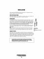
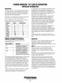
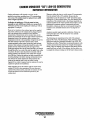
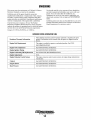

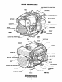
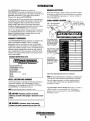
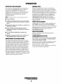
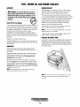
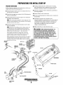
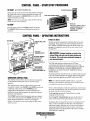
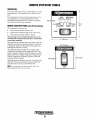
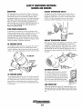
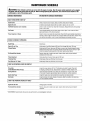
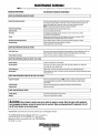
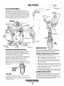
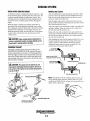
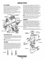
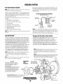
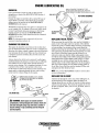
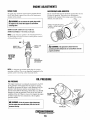
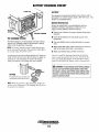
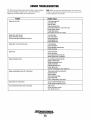
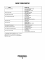
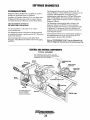
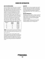
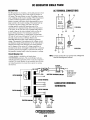
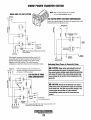
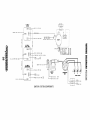
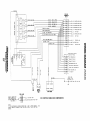
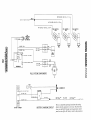
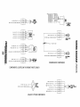
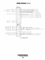
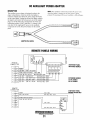
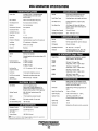
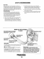
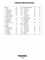
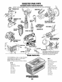


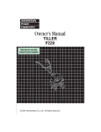

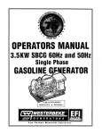


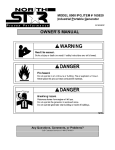
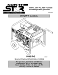

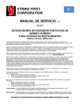

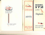


![10780-90006 - 10780A Laser Receiver for 5501A [Prefix 1948] (Mar](http://vs1.manualzilla.com/store/data/006009643_1-6e2f54ebb2199ef6df634558ba4c1bb6-150x150.png)