1
Operator's Manual
SRP-500
Samsung Elector-Mechanics
Printed In Korea
2003. 2
Safety Precautions
In using the present appliance, please keep the following safety
regulations in order to prevent any hazard or material damage.
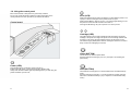
WARNING
WARNING
Violating following instructions can cause serious injury or death.
Do not plug several products in one
multi-outlet.
You must use only the supplied adapter.
It is dangerous to use other adapters.
This can provoke over-heating and a fire.
If the plug is wet or dirty, dry or wipe it before
usage.
If the plug does not fit perfectly with the
outlet, do not plug in.
Be sure to use only standardized
multi-outlets.
ONLY SUPPLIED ADAPTER
PROHIBITE
Do not pull the cable to unplug.
This can damage the cable, which is the
origin of a fire or a breakdown of the printer.
PROHIBITE
Do not plug in or unplug with your hands
wet.
You can be electrocuted.
PROHIBITE
Keep the plastic bag out of children’s
reach.
Violating following instructions can cause slight wound or damage the appliance.
Keep the desiccant out of children’s
reach.
If not, they may eat it.
PROHIBITE
If the printer falls down, it can be broken and
you can hurt yourself.
PROHIBITE
PRINTER
Use only approved accessories and do
not try to disassemble, repair or remodel it
for yourself.
Do not use the printer when it is out of
order. This can cause a fire or an
electrocution.
Call your dealer when you need these
services.
Switch off and unplug the printer before
calling your dealer.
DISASSEMBLING
PROHIBITED
TO UNPLUG
If not, a child may put the bag on his head.
PROHIBITE
If you observe a strange smoke, odor or
noise from the printer, unplug it before
taking following measures.
Switch off the printer and unplug the set from
the mains.
After the disappearance of the smoke, call
your dealer to repair it.
PRINER
Do not let water or other foreign objects in
the printer.
If this happened, switch off and unplug the
printer before calling your dealer.
Do not bend the cable by force or leave it
under any heavy object.
A damaged cable can cause a fire.
PROHIBITE
Install the printer on the stable surface.
TO UNPLUG
PRINTER
PROHIBITE
PRINTER
PRINTER
DEALER
All rights reserved. No part of this publication may reproduced, stored in a
retrieval, or transmitted in any form or by any means, electronic, mechanical,
photocopying, recording, or otherwise, without the prior written permission of
SAMSUNG ELECTRO-MECHANICS.
No patent liability is assumed with respect to the use of the information
contained herein. While every precaution has been taken in the preparation of
this book, SAMSUNG ELECTRO-MECHANICS assumed no responsibility for
errors or omissions. Neither is any liability assumed for damages resulting
from the use of the information contained herein.
Neither SAMSUNG ELECTRO-MECHANICS nor its affiliates shall be liable to
the purchaser of this product or third parties for damages, losses, costs, or
expenses incurred by purchaser or third parties as a result of : accident,
misuse, or abuse of this product or unauthorized modifications, repairs, or
alterations to this product, or (excluding the U.S) failure to strictly comply with
SAMSUNG ELECTRO-MECHANICS’ s operating and maintenance
instructions.
SAMSUNG ELECTRO-MECHANICS shall not be liable against any damages
or problems arising from the use of any options or ant consumable products
other than those designated as Original Samsung products or Samsung
Approved products by SAMSUNG ELECTRO-MECHANICS.
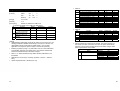
EMC and Safety standards Applied
Product Name : SRP-500
The following standards are applied only to the printers that are so labeled.
Europe :
North America :
Safety standards :
National : CB-scheme :
CE marking, TUV/GS : EN60950 ; 1999
EMI : FCC Class A
UL / C-UL : UL60950-3rd.
IEC 60950 ; 1999
WARNING
The connection of a non-shielded printer interface cable to this printer will
invalidate the EMC standards of this device.
You are cautioned that changes or modifications not expressly approved by
the party responsible for compliance could void your authority to operate the
equipment.
CE Marking
The printer conforms to the following Directive and Norms
Directive 89/336/EEC
EN 55022 Class A :1998
EN 55024 : 1998
(EN 61000-4-2 : 1995+A1 : 1998)
(EN 61000-4-3 : 1996)
(EN 61000-4-4 : 1995)
(EN 61000-4-5 : 1995)
(EN 61000-4-6 : 1996)
(EN 61000-4-11 : 1994)
EN 61000-3-2 : 1995+A1 : 1998+A2 : 1998)
EN 61000-3-3 : 1995
Directive 73/23/EEC
Safety : EN 60950 ; 1999
Notice
The contents of this manual are subject to change without notice.
Copyright © 2002 SAMSUNG ELECTRO-MECHANICS. CO., LTD
Table of contents
•
•
•
Introduction ……………………………………………………………..
1
•
Chapter 3. DIP switch
3-1 Setting the DIP switches …………………………….….…........
18
3-2 Changing the DIP switch setting ………………………………
20
•
Chapter 4. Code table ………………………………………………….
21
•
Chapter 5. Control commands list
Chapter 1. Setting up the printer
1-1. Unpacking ……………………………….………..……………
3
1-2. Choosing a place for the printer ………………………..……
4
1-3. Connecting the cables ………………………………..………
5
1-4. Installing or replacing the paper roll …………………….......
7
1-5. Installing new ink cartridge(s) ……………………..………….
9
5-1. Commands …………………………………………..…………..
33
1-6. Using the control panel ……………………………….………
11
5-2. Character code tables ………………………………………….
35
1-7. Self test …………….………………………….……………….
13
5-3. Command descriptions ……………………….………………..
36
•
Chapter 2. Troubleshooting
Chapter 6. Reference information
2-1 The printer does not start printing ……………….……………
14
6-1 Printing specification ………………………………….………....
70
2-2 The printer stops printing …………………………..………….
15
6-2 Paper specification ……………………………..………………..
70
2-3 You want to check the operation of the printer by itself ……
15
6-3 Ink cartridge specification ………………………………………
70
2-4 Printing is poor ………………………………………………….
16
6-4 Electrical characteristics ………………………….…………..…
71
2-5 You want to check a software program ………………………
17
6-5 Reliability ……………………………….……………………..….
71
6-6 Environmental conditions ……………….….............................
71
6-7 Dimension & Weight …………………………….……………….
72
6-8 Optional features …………………………………….…………..
72
Introduction
•
•
1
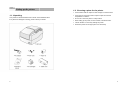
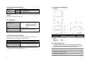
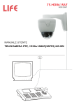
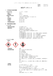
The SRP-500 is a high-quality inkjet POS printer.
This one-station printer has the following features.
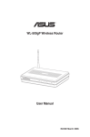
Front view
•
Compact design and light-weight.
•
High-speed printing using logic-seeking.
•
Easy to use : clamshell mechanism.
•
High reliability and long life due to the use of stepping motors for both
carriage return and paper feeding.
•
Two color printing (red/black/blue/green) available.
•
Various formats are possible because the paper feeding pitch is selectable.
•
High general control utility based on the ESC/POS (TM) standard.
•
2 drawers can be driven due to the internal drawer interface.
•
Character font (12X12, 12X14) is selectable.
•
The auto cutter uses a circular method with a high-quality blade and a long
life (Approximately 1,000,000 cuts)
•
Paper near end sensor is standard.
•
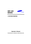
Please be sure to read the instructions in this manual carefully before
using your new printer.
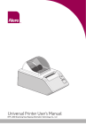
Rear view
2
Chapter 1
Setting up the printer
1-2. Choosing a place for the printer
•
Avoid locations that are subject to direct sunlight or excessive heat.
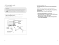
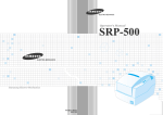
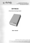
1-1. Unpacking
•
Your printer box should include the items shown in the illustration below.
If any items are damaged or missing, please contact your dealer.
Avoid using or storing the printer in a place subject to excessive
temperature or moisture.
•
Do not use or store the printer in a dirty location.
•
When setting up the printer, choose a stable, horizontal location.
•
Intense vibration or shock may damage the printer.
•
Ensure the printer has enough space to be used easily.
3
4
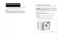
1-3. Connecting the cables
•
Plugging in AC adapter
CAUTION
• Before connecting the printer to the power supply, make sure that the
voltage and power specifications match the printer’s requirements.
• Using an incorrect power supply can cause serious damage to the
printer.
Connect the AC adapter according to the following procedure.
1) Make sure the printer is turned off.
2) Plug the AC adapter cable into the printer’s power connector.
3) Plug the power cord into the outlet, and turn on the power.
5
•
Connecting the interface cable
Connect the printer to the host ECR (host computer) though an interface
cable matching the specification of the printer and the host ECR (host
computer).
Be sure to use a drawer that matches the printer’s specification.
Depending on the interface your system uses, either connect the serial,
parallel or USB communication cable to the appropriate connector on the
back of the printer.
Cables are provided by your dealer or system installer.
Connect the interface cable according to the following procedure.
1) Turn off printer and the ECR (host computer) host.
2) Plug the interface cable into the interface connector on the printer then
fasten the screw on both sides of the connector.
3) Plug the drawer kick-out cable into the drawer kick-out connector on
the printer. (When removing the drawer kick-out cable, press on the
connector’s clip while pulling out.)
6
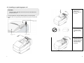
1-4. Installing or replacing paper roll
CAUTION
Notice the caution label and do not touch the auto cutter blade when
you open rear cover.
3) Remove the used
paper roll core if
there is one.
4) Insert the paper roll
as shown.
1) To prevent data loss, make sure that the printer is not receiving data.
2) Open the rear cover by pressing the open button and push the arrow mark
back.
5) Be sure to note the
correct direction that
the paper should
come off the paper
roll.
6) Pull out small amount
of paper as shown.
Then close the cover
and tear off the extra
paper by pulling it
toward the front of
the printer.
7
8
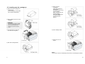
1-5. Installing new Ink cartridge(s)
1) Remove new ink cartridge from
sealed pouch.
(Hold cartridge by round plastic
tab to avoid contamination)
5) Take out old ink
cartridge(s).
Place new cartridge(s)
into carriage.
Hold plastic tab to ensure
clean installation.
Black cartridge goes into
the left carriage.
The color cartridge goes
into right carriage.
(tab faces front of
printer.)
2) Remove Mylar from face of new
cartridge.
CAUTION
Do not touch ink cartridge’s metallic
connector surface with your fingers.
Doing so will contaminate the
connector and produce bad print
quality.
3) Turn the printer on and open
the front cover of printer.
6) Close cartridge holder.
7) Close front cover of
printer.
4) Pull down cartridge holder.
Notice
The ink drop counter is automatically reset when the ink-cartridge is installed.
9
10
1-6. Using the control panel
Most of the functions of this printer are governed by software,
but you can monitor the printer’s status by looking at the lights on the
control panel and for some procedures you will use the buttons.
Control panel
Error (LED)
When this indicator light is on(but not blinking), it means that the printer is out
of paper or almost out of paper or the printer covers are open.
When this light blinking, there is an error. If you see this light blinking, turn off
the printer for a few seconds and then turn it black on.
If the light is still blinking, call your supervisor or a service person.
Cartridge (LED)
The right indicator is for the right cartridge and the left indicator for the left
cartridge. If the printer is a single color printer, the left cartridge indicator will
be used. In most cases, the left cartridge is black, and the right is a color.
This indicator light (LH/RH) blinks when the cartridge is almost out of ink and
stays on when the cartridge(s) is removed.
Clean (BUTTON)
Use this button to clean the printer head.
(See the instructions “Printing is poor” (2-4) in chapter 2 for Cleaning the
printer head.)
Power (LED)
This indicator light is on when the power is turned on.
It blinks when the printer is in the self test printing standby state.
Always wait until this indicator light stops blinking before you start using the
printer and before you turn it off.
11
Feed (BUTTON)
Use this button to feed paper or to start self test and for hexadecimal dump
mode.
(See the instructions “Self Test” (1-7) in this chapter for self test.) (See the
instructions “Hexadecimal Dump” (2-5) in chapter 2 for hexadecimal dump
mode.)
12
Chapter 2
Troubleshooting
1-7. Self test
The self test lets you know if your printer is operating properly.
It checks the control circuits, printer mechanisms, print quality, ROM version,
and DIP switch settings.
This chapter gives solutions to some printer problems you may have.
2-1. The printer does not start printing.
The test is independent of any other equipment or software, so it is a good
idea to run it when you first set up the printer or if you have any trouble. If the
self test works correctly, the problem is in the other equipment or the software,
not the printer.
•
Are any of the control panel lights on?
If no control panel lights are on, check the following:
•
Make sure that the printer is turned on.
•
Make sure that the power supply cable is correctly plugged into the printer
and to the power outlet.
•
If any of the lights are on, please check the following:
•
If the Power light is blinking, the printer is not yet ready.
Wait until the light quits blinking and the printer is ready to use.
•
If the Error light is on (but not blinking), the printer is off line.
Check to see that the covers are closed and check the paper state.
See Chapter 1 for instructions on installing or replacing the paper roll.
•
If the Error light is blinking, there is an error.
In this case, turn off the printer for a few seconds and then turn it back on.
If the light is still blinking, call your supervisor or service person.
•
If the Cartridge lights (LH/RH) is on, check the cartridges in the printer.
See chapter 1 for instruction on installing new ink cartridges.
Running the self test
1) Make sure the printer is turned off and the printer cover is closed
properly.
2) While holding down the Feed button, turn on the printer and continue to
hold until the paper begins to feed.
The self test prints the printer settings and cuts the paper and pauses.
(The power light blinks.)
3) Press the Feed button to continue printing the rolling ASCII pattern.
Repeat for the nozzle pattern, receipt pattern and NV bit image(s).
4) The self test mode terminates after printing NV bit image(s) automatically.
13
14
2-2. The printer stops printing.
2-4. Printing is poor
•
If the Error light is on (but not blinking), the printer is off line.
Check to see that the covers are closed and check the paper state.
See Chapter 1 for instructions on installing or replacing the paper roll.
Obstructed ink nozzles in the print head will lower the print quality.
Try cleaning the print head as described below:
•
If the Error light is blinking, there is an error. In this case, turn off the
printer for a few seconds and then turn it back on.
If the light is still blinking, call your supervisor or a service person.
•
•
Turn off the printer and check for a paper jam.
To clear paper jam, follow the steps below:
1) Turn off the printer and open the rear cover of the printer.
2) Remove the jammed paper and reload the paper roll as described in
Chapter1.
3) Close the rear cover
4) Turn on the printer.
Cleaning the print head
1) Make sure that the printer is turned on.
2) Press the Clean button.
The printer begins its self cleaning process, which takes less than 5
seconds.
3) When the cleaning action is finished (Power light is ON), resume
printing or run a self test (as described in Chapter 1).
4) If the printing quality has not improved, repeat this process 2-3 more
times. If the printing quality still has not improved, replace the ink
cartridge. If, after the new ink cartridge has been installed, the printing
quality has not improved, call your supervisor or a service person.
2-3. You want to check the operation of the printer by
itself.
•
Self test
Try to run the self test to check that the printer works properly.
See the self test instructions in Chapter 1 to run the self test.
If the self test does not work, contact your supervisor or a service person.
If the self test works properly, check the following:
1) Check the connection at both ends of the interface cable between the
printer and the computer. Also make sure that this cable meets the
specifications for both the printer and the computer.
2) The data transmission settings may be different between the printer and
computer. Make sure that the printer’s DIP switch settings for data
transmission are the same as the computer’s. You can see the printer’s
interface settings on your self test printout.
If the printer still does not print, contact your dealer or a qualified service
person.
15
16
Chapter 3
DIP switch settings
2-5. You want to check a software program.
•
Hexadecimal Dump
This feature allows experienced users to see exactly what data is coming
to the printer. This can be useful in finding software problems. When you
turn on the hexadecimal dump function, the printer prints all commands
and other data in hexadecimal format along with a guide section to help
you find specific commands.
Although the factory settings are best for almost all users, if you have special
requirements, you can change the DIP switch.
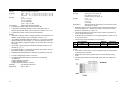
3-1. Setting the DIP switches
•
DIP switch functions
To use the hexadecimal dump feature, follow these steps:
Your printer has two sets of DIP switches.
The functions of the switches are shown in the following table.
1) After you make sure that the printer is off, open the front cover of the
printer.
DIP - SW1
2) Hold down the Feed button while you turn on the printer.
3) Close the front cover.
4) Run any software program that sends data to the printer. The printer
prints “Hexadecimal Dump” and then all the codes it receives in a two –
column format. The first column contains the hexadecimal codes and
the second column gives the ASCII characters that correspond to the
codes.
Switch
1-1
1-2
1-3
1-4
1-5
1-6
1-7
1-8
Function
Emulation Selection
Auto cutter
Cartridge
Density*1)
Special Function *2)
Near end sensor
Low ink check
EPSON
STAR
CITIZEN
EPSON-KP *3)
1-1
OFF
OFF
ON
ON
ON
OFF
Refer to the following table
Enable
one cartridge
Bold
Enable
Enable
Disable
Disable
two cartridges
Normal
Disable
Disable
Enable
Default
OFF
OFF
OFF
OFF
OFF
OFF
OFF
OFF
1-2
OFF
ON
OFF
ON
DIP - SW2 (RS232C Serial interface model)
•
A period(.) is printed for each code that has no ASCII equivalent.
5) When the printing finishes, turn off the printer.
Switch
2-1
2-2
2-3
2-4
2-5
2-6
2-7
2-8
Function
Data receive error
Hand Shaking
Word length
Parity check
Parity selection
Baud rate selection
ON
Print “?”
Reserved
DTR/DSR
7bit
Enable
EVEN
OFF
Ignore
XON/XOFF
8bit
Disable
ODD
Refer to the following table
Default
OFF
OFF
OFF
OFF
OFF
OFF
OFF
OFF
DIP - SW2 (Parallel interface model)
Switch
2-1
2-2
2-3
2-4
2-5
2-6
2-7
2-8
17
Function
Auto Line Feed
ON
Enable
Undefined
OFF
Disable
Default
OFF
OFF
OFF
OFF
OFF
OFF
OFF
OFF
18
Transmission
2400 baud
4800 baud
9600 baud
19200 baud
2-7
ON
OFF
OFF
ON
2-8
ON
ON
OFF
OFF
*1) : It may use in dark area. (like a restaurant). But printing speed to be slow down.
*2) : Enalbe = Automatically print NV bit image #1 after cutting.
*3) : EPSON Kitchen Printer mode : A alarm is generated by printer after auto-cutting
and in paper-end error. (It needs buzzer accessory)
Notice
Changes in DIP switch settings are recognized only when the printer
power is turned on or when the printer is reset by using the interface. If the
DIP switch setting is changed after the printer power is turned on, the
change does not take effect until the printer is turned on again or is reset.
3-2. Changing the DIP switch setting
If you need to change settings, follow the steps below to make your changes.
CAUTION
Turn off the printer before removing the DIP switch cover to prevent an
electric short, which can damage the printer.
1) Make sure the printer is turned off.
2) Remove the screw from the DIP switch cover.
Then take off the DIP switch cover, which is shown in the illustration
below.
3) Set the switches using a pointed tool, such as tweezers or a small
screwdriver.
4) Replace the DIP switch cover. Then secure it with the screw.
* The new settings take effect when you turn on the printer.
19
20
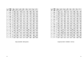
Chapter 4
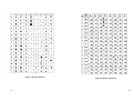
Code table
The following page show the character code tables.
To find the character corresponding to a hexadecimal number, count across
the top of the table for the left digit and count down the left column of the table
for the right digit. For example, 4A=J
Page 2 (PC850 : Multilingual)
Page 0 (PC437 : USA, Standard Europe)
(International Character Set : USA)
21
22
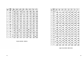
Page 3 (PC860 : Portuguese)
23
Page 4 (PC 863 : Canadian - French)
24
Page 5 (PC 865 : Nordic)
page 16 (CP1252 : WinLatin1)
25
26
page 17 (PC 866 : Russian)
27
page 18 (CP 852 : DosLatin2)
28
Page 19 (PC 858 : Euro)
Page 21 (MS-DOS 862 : Israel)
29
30
Page 22 (MS-DOS 864 : Arabic)
31
Page 23 (MS-DOS 874 :Thai)
32
Chapter 5
Control commands list
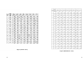
5.1.2 Commands list for SRP-500 Series. (STAR SP-320 Mode)
n
5-1. Commands
5.1.1 Commands list for SRP-500 Series. (EPSON TM-U200 Mode)
n
1
2
3
4
5
6
7
8
9
10
11
12
13
14
15
16
17
18
19
20
21
22
23
24
Command
CR
HT
LF
DLE EOT
DLE ENQ
ESC SP
ESC %
ESC &
ESC *
ESC !
ESC ESC =
ESC 2
ESC 3
ESC <
ESC ?
ESC @
ESC D
ESC E
ESC G
ESC J
ESC R
ESC U
ESC a
25
ESC c 3
26
27
28
29
30
31
32
33
34
35
36
37
38
39
ESC c 4
ESC c 5
ESC d
ESC g <0>
ESC g <n>
ESC m
ESC p
ESC r
ESC t
ESC v
ESC {
GS ( A
GS I
GS V
40
GS a
41
GS j
42
GS r
33
Description
Print and carriage return
Horizontal tab
Print and linefeed
Transmit real-time status
Real-time request to printer
Set right-side character spacing
Select/Cancel user defined characters
Define user-defined characters
Select bit-image mode
Select print mode
Turn underline mode on/off
Select peripheral device status
Select default line spacing 1/6 lpi
Set line spacing
Return home
Cancel user defined characters
Initialize printer
Set horizontal positions
Turn emphasized mode on/off
Turn double-strike mode on/off
Print and feed paper <n> vertical units
Select an international character set
Turn unidirectional printing mode on/off
Select justification
Select paper sensor to output paper end
signal
Select paper sensor to stop printing
Enable/disable panel button
Print and feed <n> line
Start macro record (For logo)
Execute macro (For logo)
Execute partial cut
Generate pulse
Select color
Select character code table
Transmit paper sensor status
Turn upside-down printing mode on/off
Execute test print
Transmit printer ID
Select cut mode and cut paper
Enable/disable Automatic Status Back
(ASB)
Enable/disable Automatic Status Back
(ASB) for ink
Transmit status
Hexadecimal
0D
09
0A
10 04
10 05
1B 20
1B 25
1B 26
1B 2A
1B 21
1B 2D
1B 3D
1B 32
1B 33
1B 3C
1B 3F
1B 40
1B 44
1B 45
1B 47
1B 4A
1B 52
1B 55
1B 61
1B 63 33
1B 63 34
1B 63 35
1B 64
1B 67 00
1B 67 <n>
1B 6D
1B 70
1B 72
1B 74
1B 76
1B 7B
1B 28 41
1D 49
1D 56
Command
1
2
3
4
5
6
7
8
9
10
BEL
FF
CR
SO
SI
DC2
DC4
CAN
EM
SUB
11
ESC BEL
12
13
14
15
16
17
18
19
20
21
22
ESC ESC 4
ESC 5
ESC @
ESC C
ESC E
ESC F
ESC M
ESC R
ESC U
ESC W 1
ESC W <1>
ESC W 0
ESC W <0>
ESC _ 1
ESC _ <1>
ESC _ 0
ESC _ <0>
ESC a
ESC d 0
ESC d 1
ESC e 1
ESC e <1>
ESC e 0
ESC e <0>
ESC f 1
ESC f <1>
ESC f 0
ESC f <0>
FS
23
24
25
26
27
28
29
30
31
32
33
Description
Deferred drive command “A” for peripheral unit 1
Page feed (Form feed)
Print and linefeed (same as LF)
Select expanded character mode
Select upside-down
Cancel upside-down character
Cancel expanded character mode(Default setting)
Cancel print data in buffer
Immediate drive command for peripheral unit2
Immediate drive command for peripheral unit 2
Adjust drive pulse width for peripheral unit (Default
setting)
Set or Cancel underline mode
Red color print selection
Red color print deselection
Initialize printer
Set page length at n lines
Emphasized print mode
Emphasized print mode deselection (Default setting)
Select 9 x 7(Half dots) character size
Select international character set
Set or cancel uni-direction mode
Select expanded character mode
Cancel expanded character mode (Default setting)
Select over-line mode
Cancel over-line mode
Feed paper n lines
Partial cut
Partial cut
Set the control panel switch invalid
Set the control panel switch valid
Set the ON LINE switch invalid
Set the ON LINE switch valid
Immediate drive command “B” for peripheral unit 1
Hexadecimal
07
0C
0D
0E
0F
12
14
18
19
1A
1B 07
1B 2D
1B 34
1B 35
1B 40
1B 43
1B 45
1B 46
1B 4D
1B 52
1B 55
1B 57 31
1B 57 01
1B 57 30
1B 57 00
1B 5F 31
1B 5F 01
1B 5F 30
1B 5F 01
1B 61
1B 64 30
1B 64 31
1B 65 31
1B 65 01
1B 65 30
1B 65 00
1B 66 31
1B 66 01
1B 66 30
1B 66 00
1C
1D 61
1D 6A
1D 72
34
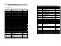
5.1.3 Commands list for SRP-500 Series. (CITIZEN iDP-3541 Mode)
n
Command
1
2
3
4
5
6
7
8
9
10
11
12
13
14
15
16
17
18
19
20
21
BEL
LF
FF n
SO
SI
DC1
DC2
DC3
CAN
SUB
ESC BEL
ESC ESC 1
ESC 2
ESC C
ESC P <0>
ESC P <1>
FS
CR
ESC * n1 n2
ESC f <1>
Description
First drawer drive command1
Paper feed command
“n”-lines paper feed command
Enlarged character command
Normal character command
Initial set command
Inverted character command
Red color print command
Clear command
Second drawer drive command
Drive pulse setting command for the first drawer
Underline command
1/9 inch paper feed preset command
2/9 inch paper feed preset command
Paper length set command
Paper partial cut command
Paper partial cut command
First drawer quick drive command
Printing
Specifying the bit image mode
Form feed
5-2. Character Code Tables
n
0
2
3
4
5
16
17
18
19
21
22
23
35
Hexadecimal
07
0A
0C n
0E
0F
11
12
13
18
1A
1B 07
1B 2D
1B 31
1B 32
1B 43
1B 50 00
1B 50 01
1C
ØD
1B 2A n1 n2
1B 66 Ø1
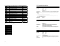
5-3. Command descriptions
HT
[Name]
Horizontal tab
[Format]
ASCII
Hex
Decimal
[Description]
Moves the print position to the next horizontal tab position.
[Notes]
• This command is ignored unless the next horizontal tab position has been
set.
•
Horizontal tab positions are set with ESC D.
•
The default tab positions are at intervals of 8 characters (columns 9, 17,
25..) for the font B (12 x 12).
[Reference]
ESC D
LF
[Name]
Print and line feed
[Format]
ASCII
Hex
Decimal
[Description]
Prints the data in the print buffer and feeds one line
based on the current line spacing.
[Note]
This command sets the print position to the beginning of
the line.
[Reference]
ESC 2, ESC 3
Page
PC437
PC850
PC860
PC863
PC865
PC1252
PC866
PC852
PC858
PC862
PC864
PC874
HT
09
10
LF
0A
10
CR
[Name]
Print and carriage return
[Format]
ASCII
Hex
Decimal
[Description]
This command prints the data in the print buffer and does
not feed the paper.
[Note]
Sets the print starting position to the beginning of the line
[Reference]
LF
CR
0D
13
36
DLE EOT n
[Name]
Real-time status transmission
[Format]
ASCII
DLE
EOT
n
Hex
10
04
n
Decimal
16
4
n
[Range]
1≤n≤4
[Description]
Transmits the selected printer status specified by n in real
time, according to the following parameters:
n = 1: Transmit printer status
n = 2: Transmit off-line status
n = 3: Transmit error status
n = 4: Transmit paper roll sensor status
[Notes]
• This command should not be used within the data sequence of another
command that consists of 2 or more bytes. For example, If you attempt to
transmit ESC 3 n to the printer, but DTR (DSR for the host computer) goes
to MARK before n is transmitted and then DLE EOT 3 interrupts before n
is received, the code <10>H for DLE EOT 3 is processed as the code for
ESC 3
<10>H.
n = 1 : Printer status
Bit
Off/On
Hex
Decimal
0
1
2
Off
On
Off
On
Off
On
On
Off
Off
Off
00
02
00
04
00
08
10
00
00
00
0
2
0
4
0
8
16
0
0
0
3
4
5
6
7
Function
Not used. Fixed to Off.
Not used. Fixed to On.
Drawer kick-out signal is LOW (connector pin 3)
Drawer kick-out signal is HIGH (connector pin 3)
On-line.
Off-line.
Not used. Fixed to On.
Not used. Fixed to Off.
Not used. Fixed to Off.
Not used. Fixed to Off.
n = 2 : Off-line status
Bit
Off/On
Hex
Decimal
Function
0
1
2
Off
On
Off
On
Off
On
On
Off
On
Off
On
Off
00
02
00
04
00
08
10
00
20
00
40
00
0
2
0
4
0
8
16
0
32
0
64
0
Not used. Fixed to Off.
Not used. Fixed to On.
Cover is closed (front & rear)
Cover is open (front or rear)
Paper is not being fed by using the paper feed button.
Paper is being fed by the paper feed button.
Not used.
Fixed to On.
No paper-end stop.
Printing stops due to paper end.
No error. Error occurs.
Not used. Fixed to Off.
3
4
5
6
7
Bit 5 : On (printing stops due to paper-end) when printing stops due to paperend detected by the paper-end sensor or the paper near-end enabled
by using the ESC c 4.
37
38
DLE ENQ n
n = 3 : Error status
Bit
Off/On
Hex
Decimal
0
1
2
Off
On
Off
On
Off
On
On
Off
On
Off
On
Off
00
02
00
04
00
08
10
00
20
00
40
00
0
2
0
4
0
8
16
0
32
0
64
0
3
4
5
6
7
Function
Not used. Fixed to Off.
Not used. Fixed to On.
No mechanical error.
Mechanical error occurred.
No auto-cutter error.
Auto-cutter error occurs.
Not used. Fixed to On.
No unrecoverable error.
Unrecoverable error occurs.
Automatic recover error.
No automatic recover error.
Not used. Fixed to Off.
Bit 2 : If these errors occur due to paper jams or the like, it is possible to
recover by correcting the cause of the error and executing DLE ENQ 2.
If an error due to a circuit failure (e.g. wire break) occurs, it is
impossible to recover.
[Name]
Real-time request to printer
[Format]
ASCII
Hex
Decimal
Off/On
Hex
Decimal
0
1
Off
On
Off
00
02
00
0
2
0
On
0C
12
On
Off
On
Off
10
00
60
00
16
0
96
0
2, 3
4
5, 6
7
Function
Not used. Fixed to Off.
Not used. Fixed to On.
Paper near-end sensor. Paper adequate.
Paper near-end is detected by the paper near-end
sensor.
Not used. Fixed to On.
Paper end sensor. Paper adequate.
Paper end is detected by the paper end sensor.
Not used. Fixed to Off.
ENQ
05
5
n
n
n
[Range]
n=2
[Description]
The printer responds to a request from the host specified
by n.
n = 2: Recovers from an error after clearing the receive
and print buffers.
[Notes]
• This command should not be used within the data sequence of another
command that consists of two or more bytes. For example,
If you attempt to transmit ESC 3 n to the printer, but DTR (DSR for the
host computer) goes to MARK before n is transmitted, and DLE ENQ 2
interrupts before n is received, the code <10>H for DLE ENQ 2 is
processed as the code for ESC 3 <10>H.
•
This command n = 2 is valid only when a mechanical error or an autocutter error has occurred.
•
DLE ENQ 2 enables the printer to recover from an error after clearing
the data in the receive buffer and the print buffer.
The printer retains the settings (by ESC !, ESC 3, etc.) in effect when the
error occurred. The printer can be initialized completely by using this
command and ESC @. This command is enabled only for errors that have
the possibility of recovery
n = 4 : Continuous paper sensor status
Bit
DLE
10
16
ESC SP n
39
[Name]
Set right-side character spacing
[Format]
ASCII
Hex
Decimal
[Range]
0 ≤ n ≤ 255
[Description]
Sets the character spacing for the right side of the
character to [ n x 0.122 mm {1/208 inches}] .
[Notes]
The right-side character spacing for double-width mode is
twice the normal value.
[Default]
n=0
ESC
1B
27
SP
20
32
n
n
n
40
ESC % n
ESC ! n
[Name]
Select print mode(s)
[Format]
ASCII
Hex
Decimal
[Range]
0 ≤ n ≤ 255
[Description]
Selects print mode(s) using n as follows:
Bit
Off/On
Hex
Decimal
0
Off
On
Off
On
Off
On
Off
On
Off
On
00
01
00
08
00
10
00
20
00
80
0
1
0
8
0
16
0
32
0
128
1
2
3
4
5
6
7
ESC
1B
27
!
21
33
n
n
n
[Name]
Select/cancel user-defined character set
[Format]
ASCII
Hex
Decimal
[Range]
0 ≤ n ≤ 255
[Description]
Selects or cancels the user-defined character set.
%
25
37
n
n
n
When the Least Significant Bit (LSB) is 0, the userdefined character set is canceled and the internal
character set is enabled.
Function
Character font A (12 x 14) selected.
Character font B (12 x 12) selected.
Undefined.
Undefined.
Emphasized mode not selected.
Emphasized mode selected.
Double-height mode not selected.
Double-height mode selected.
Double-width mode not selected.
Double-width mode selected.
Undefined.
Underline mode not selected.
Underline mode selected.
ESC
1B
27
When the LSB is 1, the user-defined character set is
selected.
[Notes]
• When the downloaded character set has been released, the internal
character set is specified automatically.
[Default]
n=0
[Reference]
ESC &, ESC ?
[Notes]
• When both double-height and double-width modes are selected, quadruple
size characters are printed.
•
Underlining is added to the entire width of each character, including the
space to the right of a character, but is not added to portions of lines that
were skipped by means of an HT.
[Default]
n=1
[Reference]
ESC E, ESC –
41
42
ESC & y c1 c2 [x1 d1...d(y x x1)]...[ xk d1... d(y x xk)]
[Name]
Define user-defined characters
[Format]
ASCII ESC &
Hex
1B
26
Decimal 27
38
[Range]
y=2
32 ≤ c1 ≤ c2 ≤ 255
0 ≤ x ≤ 14 (Font A)
0 ≤ x ≤ 12 (Font B)
0 ≤ d1 ... d(y x x) ≤ 255
y c1 c2 [x1 d1...d(y x x1)]...[ xk d1... d(y x xk)]
y c1 c2 [x1 d1...d(y x x1)]...[ xk d1... d(y x xk)]
y c1 c2 [x1 d1...d(y x x1)]...[ xk d1... d(y x xk)]
[Description]
Defines user-defined characters.
• y specifies the number of bytes in the vertical direction.
•
c1 specifies the beginning character code for the definition, and c2
specifies the final code. When only one character is desired, use c1 = c2.
•
x specifies the number of dots in the horizontal direction.
ESC * m nL nH d1...dk
[Name]
Select bit-image mode
[Format]
ASCII ESC * m nL nH d1...dk
Hex 1B 2A m nL nH d1...dk
Decimal 27 42 m nL nH d1...dk
[Range]
m = 0, 1
0 ≤ nL ≤ 255
0 ≤ nH ≤ 3
0 ≤ d ≤ 255
[Description]
Selects a bit-image mode using m for the number of dots
specified by nL and nH
Divide the number of dots to be printed by 256. The interger answer is nH
and the remainder is nL. Therefore, the number of dots in the horizontal
direction is calculated by nL + 256 x nH.
•
•
[Notes]
• Consecutive character codes for multiple characters can be defined in one
definition. When specifying only one character, specify c1 = c2.
If the bit-image data input exceeds the number of dots to be printed on a
line, the excess data is ignored.
•
d indicates the bit-image data. Set a corresponding bit to 1 to print a dot or
to 0 to not print a dot.
•
•
The bit-image modes selectable by m are as follows.
"d" is definition data that indicates the pattern for " x" dots in the horizontal
direction starting from the left edge. If " x" does not satisfy the number of
dots in the character configuration pattern, the remaining dots on the right
are spaces.
•
The number of bytes required to download a character definition for one
character is " y" x " x".
•
In the definition data, a "1" represents a dot that is to be printed, and a "0"
represents a dot that is not to be printed.
•
Independent downloaded character definitions are possible for each font.
•
The font is selected by the "ESC !" command.
•
The defined downloaded characters are cleared in the following
circumstances:
1) When "ESC @" is executed
2) When deleted by "ESC ?"
3) When the printer is reset or turned off
[Default]
The internal character set
[Reference]
ESC %, ESC ?
43
m
0
1
No. of Vertical
Dots
8
8
Dot Density
Single Density
Double Density
Adjacent
Dot
Permitted
Permitted
Maximum
number of dots
252
504
[Notes]
• If the values of m and nH are out of the specified range, the following data
is processed as normal data.
•
After printing a bit image, the printer returns to normal data processing
mode.
•
The relationship between the image data and the dots to be printed is as
follows.
44
ESC - n
ESC 3 n
[Name]
Turn underline mode on/off
[Format]
ASCII
Hex
Decimal
[Range]
n = 0, 1, 48, 49
ESC
1B
27
–
2D
45
n
n
n
[Name]
Set line spacing
[Format]
ASCII
Hex
Decimal
ESC
1B
27
3
33
51
n
n
n
[Range]
0 ≤ d ≤ 255
[Description]
Turns underline mode on or off,
• When n = 0 or 48, underline mode is turned off.
[Description]
Sets the line spacing to [ n x (1/192)] inches.
[Default]
n = 32 (1/6 inch)
•
[Reference]
ESC 2
When n = 1 or 49, underline mode is turned on.
[Notes]
• Underlines can be printed for all characters, but not for the space set by
HT.
•
This command and ESC ! turn underline mode on or off in the same way.
ESC <
•
If n is out of the specified range, this command is ignored.
[Name]
Return home
[Format]
ASCII
Hex
Decimal
[Description]
Moves the print head to the standby position.
[Default]
n=0
[Reference]
ESC !
ESC 2
[Name]
Select default line spacing
[Format]
ASCII
Hex
Decimal
ESC
1B
27
2
32
50
[Description]
Selects default (1/6-inch) line spacing.
[Reference]
ESC 3
ESC
1B
27
<
3C
60
[Notes]
• The leftmost end is detected by the home position sensor.
•
Since the home position is detected when this command is executed, the
printing position may shift after this command is executed.
ESC = n
[Name]
Select device
[Format]
ASCII
Hex
Decimal
[Range]
n=1
[Description]
• n = 1 ; enable
Selects device to which host computer sends data.
•
=
3D
61
n
n
n
n = 2 ; disable
[Default]
45
ESC
1B
27
n=1
46
ESC ? n
ESC D n1... nk NUL
[Name]
Cancel user-defined characters
[Name]
Set horizontal tab positions
[Format]
ASCII
Hex
Decimal
[Format]
ASCII
Hex
Decimal
[Range]
32 ≤ n ≤ 255
[Range]
[Description]
Cancels user-defined characters.
1 ≤ d ≤ 255
0 ≤ k ≤ 32
ESC
1B
27
?
3F
63
n
n
n
ESC
1B
27
D
44
68
n1...nk NUL
n1...nk 00
n1...nk 0
[Notes]
• This command cancels the pattern defined for the character code specified
by n. After the user-defined characters is cancelled, the corresponding
pattern for the internal character is printed.
[Description]
Sets horizontal tab positions.
• n specifies the column number (counted from the beginning of the line) for
setting a horizontal tab position.
•
This command deletes the defined pattern for the specified code in the
character font selected by the "ESC !" command.
•
If a user-defined character has not been defined for the specified character
code, the printer ignores this command.
[Notes]
• The tab position is set at [character width x n] from the beginning of the
line. The character width includes the right-side space of the character,
and is twice the normal value when double-width is specified.
[Reference]
ESC &, ESC %
ESC @
[Name]
Initialize printer
[Format]
ASCII
Hex
Decimal
[Description]
ESC
1B
27
@
40
64
Clears the data in the print buffer and resets the printer
mode to the mode that was in effect when the power was
turned on.
[Notes]
• The DIP switch settings are not checked again.
•
47
•
k indicates the total number of horizontal tab positions to be set.
•
This command deletes horizontal tab positions that have already been set.
•
When "n = 8" has been set for the horizontal tab position, the printing
position moves to the ninth digit when HT is executed.
•
Up to 32 tab positions can be set. Data exceeding 32 tab positions is
processed as normal data. Input <n>k in ascending order and place a NUL
code <00>H at the end when <n>k is less than or equal to the preceding
value <n>k-1, tab setting is finished and the following data is processed as
normal data.
•
ESC D NUL cancels all horizontal tab positions.
•
The previously specified horizontal tab positions do not change, even if the
character width changes.
[Default]
The default tab positions are at intervals of 8 characters
(columns 9, 17, 25, ...) for the font B (12 x 14).
[Reference]
HT
The data in the receive buffer is not cleared.
48
ESC E n
ESC G n
[Name]
Turn emphasized mode on/off
[Format]
ASCII
Hex
Decimal
[Range]
32 ≤ n ≤ 255
ESC
1B
27
E
45
69
n
n
n
[Name]
Turn double-strike mode on/off
[Format]
ASCII
Hex
Decimal
[Range]
0 ≤ n ≤ 255
ESC
1B
27
G
47
71
n
n
n
[Description]
Turns emphasized mode on or off.
• When the LSB of n is 0, emphasized mode is turned off.
[Description]
Turns double-strike mode on or off.
• When the LSB of n is 0, double-strike mode is turned off.
•
•
When the LSB of n is 1, emphasized mode is turned on.
When the LSB of n is 1, double-strike mode is turned on.
[Notes]
* Printing is slower in emphasized mode.
• Only the lowest bit of n is enabled.
[Notes]
* Printing is slower in double-strike mode.
• Only the lowest bit of n is enabled.
•
The printer does not emphasize bit-images.
•
The printer does not double-strike for bit-images.
•
This command and ESC ! turn on and off emphasized mode in the same
way. The last proceeded command becomes effective.
•
Printer output is the same in double-strike and in emphasized (ESC E).
[Default]
n=0
•
Printer output is the same in double-strike (ESC G) and in emphasized.
[Reference]
ESC E
[Default]
n=0
[Reference]
ESC !, ESC G
ESC J n
[Name]
Print and feed paper
[Format]
ASCII
Hex
Decimal
[Description]
Prints the data in the print buffer and feeds the paper
[ n x 0.122mm {1/192 inches}] .
ESC
1B
27
J
4A
74
n
n
n
[Notes]
• After printing is completed, this command sets the print starting position to
the beginning of the line.
•
49
This command has no effect on the line feed amount set by the "ESC 2"
command or the "ESC 3" command.
50
ESC R n
ESC a n
[Name]
Select an international character set
[Name]
Select justification
[Format]
ASCII
Hex
Decimal
[Format]
ASCII
Hex
Decimal
[Range]
0 ≤ n ≤ 10
[Range]
0 ≤ n ≤ 2, 48 ≤ n ≤ 50
[Description]
Selects an international character set n from the following
table:
[Description]
Aligns all the data in one line to the specified position.
ESC
1B
27
R
52
82
n
0
1
2
3
4
5
6
7
8
9
10
[Default]
n
n
n
a
61
97
n
n
n
n selects the type of justification as follows:
Character set
U.S.A
France
Germany
U.K.
Denmark I
Sweden
Italy
Spain I
--Norway
Denmark II
ESC
1B
27
n
0, 48
1, 49
2, 50
Justification
Left justification
Centering
Right justification
[Notes]
• The command is enabled only when input at the beginning of the line.
•
n=0
A portion of data skipped by means of HT is also target data for the
justification function.
[Default]
n=0
[Example]
Left justification
ESC U n
[Name]
Turn unidirectional printing mode on/off
[Format]
ASCII
Hex
Decimal
[Range]
ESC
1B
27
U
55
85
n
n
n
0 ≤ n ≤ 255
ABC
ABCD
ABCDE
Centering
ABC
ABCD
ABCDE
Right justification
ABCC
ABCDC
ABCDEC
[Description]
Turns unidirectional printing mode on or off
• When the LSB of n is 1, turn on unidirectional printing mode.
[Notes]
• Only the lowest bit of n is enabled.
•
To avoid horizontal printing misalignment, unidirectional printing mode
should be used.
[Default]
51
n=0
52
ESC c 3 n
ESC c 4 n
[Name]
Select paper detector(s)to output paper end signals
[Name]
Select paper sensor(s)to stop printing
[Format]
ASCII
Hex
Decimal
[Format]
ASCll
Hex
Decimal
[Range]
0 ≤ n ≤ 255
[Range]
0 ≤ n ≤ 255
[Description]
Selects paper detector(s) to output paper end signals,
using n as follows:
[Description]
Selects the paper sensor(s) used to stop printing when a
paper-end is detected, using n as follows :
Bit
Off/On
Hex
Decimal
0
Off
On
Off
On
Off
On
Off
On
-
00
01
00
02
00
04
00
08
-
0
1
0
2
0
4
0
8
-
1
2
3
4
5
6
7
ESC
1B
27
c
63
99
3
33
51
n
n
n
Function
[Notes]
• It is possible to select multiple detectors to output signals.
•
Then, if any of the detectors detects a paper end, the paper end signal is
output.
•
Detectors are switched when executing this command.
•
Because of this, the paper-out signal switching may delay depending on
the receive buffer state.
[Default]
53
n = 15
Bit
Off/On
Hex
Decimal
0
Off
On
Off
On
-
00
01
00
02
-
0
1
0
2
-
Paper roll near end sensor disabled.
Paper roll near end sensor enabled.
Paper roll near end sensor disabled.
Paper roll near end sensor enabled.
Paper roll end detector disabled.
Paper roll end detector enabled.
Paper roll end detector disabled.
Paper roll end detector enable.
Undefined
Undefined
Undefined
Undefined
1
2
3
4
5
6
7
ESC
18
27
c
63
99
4
34
52
n
n
n
Function
Paper roll near end sensor disabled.
Paper roll near end sensor enabled.
Paper roll near end sensor disabled.
Paper roll near end sensor enabled.
Undefined
Undefined
Undefined
Undefined
Undefined
Undefined
[Notes]
• The printer goes off-line after printing stops.
•
The paper roll near-end sensor is an option, therefore, if the paper roll
near-end sensor is enabled by this command when the sensor is not
equipped, it does not stop printing.
•
The paper roll near-end sensor is enabled when either bit 0 or 1 is 1.
•
The paper roll end sensor is a sensor which is always used to make an
effective to stop printing.
[Default]
n=0
54
ESC c 5 n
ESC g<0> <k> [<nH> <nL> ]k[d1…dm]k
[Name]
Enable/disable panel buttons
[Format]
ASCII
Hex
Decimal
[Range]
ESC
1B
27
c
63
99
5
35
53
[Name]
n
n
n
0 ≤ n ≤ 255
[Description]
Enables or disables the panel buttons.
• When the LSB of n is 0, the panel buttons are enabled.
•
[Format]
[Range]
Start macro record
ASCII
ESC g
Hex
1B
67 00 <k> [<nH> <nL> ]k[d1…dm]k
Decimal
27
103 00 <k> [<nH> <nL> ]k[d1…dm]k
k ≤ 10
0 ≤ nL ≤ 255
When the LSB of n is 1, the panel buttons are disabled.
[Notes]
• Only the least significant bit of "n" is valid.
0 ≤ nH ≤ 255
•
When the panel buttons are disabled, no buttons on the panel are usable.
0 ≤ d ≤ 255
•
If "disabled" is set, the paper feed switch no longer functions.
[Default]
<0><k> [<nH> <nL> ]k[d1…dm]k
[(256×nH) + nL ]1 + …..+ [(256×nH) + nL ]k < 2Mbit
[Description]
n=0
Start macro definition (Define logo)
• k = the number of total macro index
• (256×nH) + nL = the Length of each macro
• m = (256×nH) + nL.
ESC d n
[Name]
Print and feed n lines
[Format]
ASCII
Hex
Decimal
ESC
1B
27
d
64
100
n
n
n
[Range]
0 ≤ n ≤ 255
[Description]
Prints the data in the print buffer and feeds n lines.
[Notes]
• This command sets the print starting position to the beginning of the line.
•
[Notes]
The SRP-500 Printer maintains a 2M bit (256KB) section
of flash memory to save user information
• This function is useful define NV bit image (Logo).
[Reference]
User easily download Logo to printer using SRP-500
StoreMaker Utility.
ESC g n
[Name]
Execute Macro
[Format]
ASCII
The amount of paper fed per line is based on the value set using the line
spacing command (ESC 2 or ESC 3)
[Reference]
ESC
g
n
Hex
1B
67
n
Decimal
27
103
n
[Range]
1 ≤ n ≤10
[Description]
Execute macro using the parameter by n.
[Notes]
• n = Macro index number.
55
56
ESC m
ESC r n
[Name]
Execute partial cut
[Format]
ASCII
Hex
Decimal
[Description]
Execute partial cut with one point uncut
ESC
1B
27
m
6D
109
[Name]
Select print color
[Format]
ASCII
Hex
Decimal
ESC
1B
27
[Range]
n = 0, 1, 48, 49
[Description]
Selects the print color.
n
0, 48
1, 49
ESC p m t1 t2
[Name]
Generate pulse
[Format]
ASCII
Hex
Decimal
ESC
1B
27
p
70
112
m t1 t2
m t1 t2
m t1 t2
[Range]
m = 0, 1, 48, 49
0 ≤ t1 ≤ 255
0 ≤ t2 ≤ 255
[Description]
Outputs the pulse specified by t1 and t2 to connector pin
m as follows:
n
0
1
n
n
n
Selected color
Black
Red
[Notes]
• Valid only when input at the beginning of a line.
[Default]
n=0
ESC t n
[Name]
Select character code table
[Format]
ASCII
Hex
Decimal
[Range]
n = 0, 2, 3, 4, 5, 16, 17, 18, 19, 21, 22, 23
[Description]
Selects a page n from the character code table.
Connector Pin
Drawer kick-out connector pin 2
Drawer kick-out connector pin 5
[Notes]
• The pulse ON time is [ t1 x 2] ms and the OFF time is [ t2 x 2] ms.
•
r
72
114
ESC
1B
27
n
When t2 < t1, the printer processes t1 x 2 ms.
0
2
3
4
5
16
17
18
19
21
22
23
[Reference]
[Default]
t
74
116
n
n
n
Page
PC437
PC850
PC860
PC863
PC865
PC1252
PC866
PC852
PC858
PC862
PC864
PC874
n=0
[Reference]
57
58
ESC { n
ESC v
[Name]
[Format]
[Description]
Transmit paper sensor status
[Name]
Turns on/off upside-down printing mode
ASCII
ESC
v
[Format]
Hex
1B
76
ASCII
Hex
Decimal
Decimal
27
118
[Range]
0 ≤ n ≤ 255
Transmits the status of paper sensor( s) as 1 byte of data
[Notes]
• GS r 1 can also be used to check the status. GS r is recommended for
transmitting the paper sensor status. ESC v is not a recommended
command.
•
•
•
When DTR/DSR control is selected by DIP switch (Handshaking) with a
serial interface, the printer transmits the status after confirming that the
host is ready to receive data. If the host computer is not ready to receive
data, the printer waits until the host becomes ready.
When XON/XOFF control is selected by DIP switch (Handshaking) with a
serial interface, the printer transmits the status without confirming whether
the host computer can receive data.
The peripheral device status to be transmitted is as follows:
Bit
0,1
2,3
4
5
6
7
Off/On
Off
On
Off
On
Off
Off
Off
Off
Hex
00
03
00
0C
00
00
00
00
Decimal
0
3
0
12
0
0
0
0
Function
Paper roll near end sensor : paper adequate
Paper roll near end sensor : paper near end
Paper roll end sensor : paper present
Paper roll end sensor : paper not present
Fixed
Undefined
Undefined
Undefined
ESC
1B
27
{
7B
123
n
n
n
[Description]
Turns upside-down printing mode on or off.
• When the LSB of n is 0, upside-down printing mode is turned off.
•
When the LSB of n is 1, upside-down printing mode is turned on.
[Notes]
• Only the lowest bit of n is effective.
•
This command is enabled only when input at the beginning of a line.
•
In upside-down printing mode, the printer rotates the line to be printed by
180° and then prints it.
[Default]
n=0
[Example]
Upside-down printing mode is furned off
Upside-down printing mode is furned on
Paper feed directioPaper feed direction
59
60
GS ( A pL pH n m
GS I n
[Name]
Execute test print
[Name]
Transmit printer ID
ASCII
GS
(
A
pL
pH
n
m
[Format]
Hex
1D
28
41
pL
pH
n
m
ASCII
Hex
Decimal
Decimal
29
40
65
pL
pH
n
m
[Format]
[Range]
(pL + (pH ×256) ) = 2
1 ≤ m ≤ 3, 49 ≤ n ≤ 51
[Description]
• Executes a test print with a specified test pattern on a specified paper.
pL and pH specifies the number of the parameter such as n,m to (pL + (pH
×256) ) bytes.
•
n specifies the paper to be tested.
n
0, 48
1, 49
2, 50
•
Paper
Basic sheet (paper roll)
Paper roll
m specifies a test pattern.
n
1, 49
2, 50
3, 51
Test pattern
Hexadecimal dump
Printer status print
Rolling pattern print
[Notes]
• When the hexadecimal dump is printed by this command, the data which
is transmitted after the command may not be printed because the printer
clears the receive buffer. To avoid this, transmit data from the host after
the printer prints the starting message of the hexadecimal dump.
•
61
I
49
73
n
n
n
[Range]
1≤n≤3
[Function]
Transmits the printer ID specified by n as follows:
(where pL = 2, pH = 0)
0 ≤ n ≤ 2, 48 ≤ n ≤ 50
•
GS
1D
29
Bit
1,49
2,50
3,51
Printer ID
Specification
Printer model ID
Type ID
ROM version ID
SRP-500 series See table
below
ROM version
ID (hexadecimal)
0D
n = 2, Type ID
Bit
Off/On
Hex
Decimal
0
Off
On
Off
On
Off
Off
00
01
00
02
00
00
0
1
0
2
0
0
1
2
3
4
5
6
7
Function
Two-byte character code not supported.
Two-byte character code supported.
Auto cutter not equipped.
Auto cutter equipped.
Undefined.
Undefined.
Not used. Fixed to Off.
Undefined.
Undefined.
Not used. Fixed to Off.
[Notes]
• The printer ID is transmitted when the data in the receive buffer is
developed. Therefore, there may be a time lag between receiving this
command and transmitting the status, depending on the receive buffer
status.
[Reference]
This command is enabled only when processed at the beginning of a line
in standard mode.
62
① GS V m
Bit
0
② GS V m n
[Name]
Feeds paper for cutting position.
1
[Format]
① 1 ASCll GS
Hex
1D
Decimal 29
V
56
86
m
m
m
2
② ASCll
GS
Hex
1D
Decimal 29
V
56
86
m
m
m
[Range]
① m = 1, 49
② m = 66, 0 ≤ n ≤ 255
[Description]
Feeds paper for cutting position as follows;
3
n
n
n
Bit
Print mode
1, 49
66
Partial cut (one portion left uncut)
Feeds paper for ( cutting position + [n x 0.122 mm {1/192 inches}]), and partial cut.
[Notes]
• This command is effective only at the beginning of a line.
4
5
6
7
Off/On
Off
On
Off
On
Off
On
Off
On
-
Hex
00
01
00
02
00
04
00
08
-
Decimal
0
1
0
2
0
4
0
8
-
Status for ASB
Drawer kick-out connector pin 3 status disabled.
Drawer kick-out connector pin 3 status enabled.
On-line/off-line disabled.
On-line/off-line enabled
Error status disabled.
Error status enabled.
Paper roll sensor status disabled.
Paper roll sensor status enabled.
Undefined.
Undefined.
Undefined.
Undefined.
[Notes]
• Even if only one of the statuses is enabled, the status is sent when this
command is executed. Subsequently, whenever the state of a valid status
changes, that status is sent. In this case, because the current state is
shown for each status, there is a possibility of a state change for a status
for which ASB is not enabled.
•
If all statuses are disabled, the Automatic Status Back (ASB) function is
disabled.
•
When n = 0, the printer feeds the paper to the cutting position.
•
When transmitting a status, the printer transmits only four bytes.
•
When n , 0,the printer feeds the paper to (cutting position +[ n x 0.122 mm
{1/192 inches}]).
•
Four bytes of status data must be consecutive, except for XOFF code.
•
This command is executed when the data in the receive buffer is
developed. Therefore, there may be a time lag between receiving this
command and transmitting the status, depending on the receive buffer
status.
GS a n
[Name]
Enable/Disable Automatic Status Back
•
[Format]
ASCII
Hex
Decimal
When the printer is disabled by ESC = (Select peripheral device), this
command is disabled but ASB is not disabled.
•
The status to be transmitted are as follows:
GS
1D
29
a
61
97
n
n
n
[Range]
0 ≤ n ≤ 255
[Description]
Enables or disables ASB and specifies the status items to
include, using n as follows:
63
64
First byte (printer information)
Bit
0
1
2
3
4
5
6
7
Off/On
Off
Off
Off
On
Off
On
On
Off
On
Off
On
Off
Hex
00
00
00
04
00
08
10
00
20
00
40
00
Decimal
0
0
0
4
0
8
16
0
32
0
64
0
Third byte (paper sensor information)
Status for ASB
Not used. Fixed to Off.
Not used. Fixed to Off.
Drawer kick-out connector pin 3 is LOW.
Drawer kick-out connector pin 3 is HIGH.
On-line.
Off-line.
Not used. Fixed to On.
Cover is close (Front & rear)
Cover is open (Front or rear)
Paper is not being fed by the paper feed button.
Paper is being fed by the paper feed button.
Not used. Fixed to Off.
Bit
0, 1
2, 3
Off/On
Off
On
Off
Hex
00
03
00
Decimal
0
3
0
4
5
6
7
On
Off
Off
Off
Off
0C
00
00
00
00
12
0
0
0
0
Status for ASB
Paper near-end sensor: paper adequate. Paper
near-end sensor: paper near end.
Paper end sensor: paper present. Paper end
sensor:
no paper present.
Not used. Fixed to Off.
Not used. Fixed to Off.
Not used. Fixed to Off.
Not used. Fixed to Off.
Fourth byte (paper sensor information)
Second byte (printer information)
Bit
0
1
2
3
4
5
6
7
65
Off/On
Off
Off
Off
On
Off
On
Off
Off
On
Off
Off
Hex
00
00
00
04
00
08
00
00
20
00
00
Decimal
0
0
0
4
0
8
0
0
32
0
0
Status for ASB
Not used. Fixed to Off.
Not used. Fixed to Off.
No mechanical error.
Mechanical error.
No auto cutter error.
Auto cutter error occurred.
Not used. Fixed to Off.
No unrecoverable error.
Unrecoverable error.
Not used. Fixed to Off.
Not used. Fixed to Off.
Bit
0
1
2
3
4
5
6
7
Off/On
On
On
On
On
Off
Off
Off
Off
Hex
01
02
04
08
00
00
00
00
Decimal
1
2
4
8
0
0
0
0
Status for ASB
Not used. Fixed to On.
Not used. Fixed to On.
Not used. Fixed to On.
Not used. Fixed to On.
Not used. Fixed to Off.
Not used. Fixed to Off.
Not used. Fixed to Off.
Not used. Fixed to Off.
[Default] n = 0
[Reference]
66
•
GS j n
[Name]
Bit
Enable/disable Automatic Status Back (ASB) for ink
[Format]
[Range]
ASCII
GS
j
n
Hex
1D
6A
n
Decimal
29
106
n
Status A :
1
2
0 ≤ n ≤ 255
3
[Default]
n=0
4
[Description]
Enables of disables the ASB for ink
5
6
7
n specifies the status for the ASB in the table below :
Bit
0
1
2~7
Function
Disable online/offline status
of the ink mechanism
Enable online/offline status
of the ink mechanism
Disable the status of ink
detection
Enable the status of ink
detection
Reserved
Binary
Hexadicimal
Decimal
0
00
0
1
01
1
Bit
0
00
0
0
1
02
2
1
0
2~5
6
7
0
00
[Notes]
• ASB(Automatic Status Back) transmits the status such as ink near-end, ink
cartridge installed/not installed automatically to the printer in real-time. It is
called [ASB function] and the status is [ASB status]. If you use ASB,
application can acquire the printer change in real-time and passively.
•
Function
Ink near-end not detected (1st color)
Ink near-end detected (1st color)
Ink end not detected (1st color)
Ink end detected (1st color)
Ink cartridge installed (1st color)
Ink cartridge not installed (1st color)
Ink cartridge installed (2nd color)
Ink cartridge not installed (2nd color)
Reserved
Cleaning is not being performed
Cleaning is being performed
Fixed
Fixed
0
•
•
Hexadicimal
00
01
00
02
00
04
00
08
00
20
40
00
Decimal
0
1
0
2
0
4
0
8
0
32
64
0
Binary
0
1
0
1
1
0
Hexadicimal
00
01
00
02
40
00
Decimal
0
1
0
2
64
0
Status B :
Function
Ink near-end not detected (2nd color)
Ink near-end detected (2nd color)
Ink end not detected (2nd color)
Ink end detected (2nd color)
Reserved
Fixed
Fixed
ASB is enabled if any status item is selected. The printer transmits a 4byte status when this command is executed. The printer automatically
transmits a 4-byte status message whenever the status changes. Each
status represents the current status.
Enabling any status (except n =0) starts ASB. Then the current ASB status
is transmitted. After that, when ASB is active, the selected enabled ASB
status is transmitted each time the status changes.
Bit
0
•
When n = 0, ASB is disabled. During ASB is disabled, ASB status is not
transmitted.
n
Status
Online/offline status of ink
mechanism
1
Ink detection status
•
ASB status for ink is 4-byte, consisting of [header + status A + status B +
NUL].
•
Header is [Hexadecimal = 35H/Decimal = 53]
67
Binary
0
1
0
1
0
1
0
1
0
1
1
0
ASB status
ASB status
Detect ink end
Detect ink cartridge
Cleaning
Detect ink near-end
Detect ink end
Detect ink cartridge
Bit
Status A: Bit 1
Status A: Bit 2
Status A: Bit 5
Status A: Bit 0
Status A: Bit 1
Status A: Bit 2
68
Chapter 6
GS r n
[Name]
Transmit status
[Format]
ASCII GS r n
Hex 1D 72 n
Decimal 29 114 n
Reference information
6-1. Printing specification
[Range]
1 ≤ n ≤ 2, 49 ≤ n ≤ 50
[Description]
Transmits the status specified by n as, follows:
n
0, 48
1,49
Function
Transmits paper sensor status
Transmits drawer kick-out connector status
[Notes]
• This command is executed when the data in the receive buffer is
developed. Therefore, there may be a time lag between receiving this
command and transmitting the status, depending on the receive buffer
status.
•
Printing method
Printing direction
Resolution
Characters per line
Printing speed
Printing Width
Line Interval
Character sets
Character font
Serial ink jet matrix method
Bidirectional(logic seeking) with friction feed
104 x 96(dpi): Text
208 x 96(dpi): Graphic
Max 42(characters)
6.5 LPS (Lines Per Second)
at 40 columns
61.5mm
4.233mm (1/6”)
Alphanumeric characters: 95
International characters: 32
Extended graphics: 128 x 12 pages
12 x 12 / 12 x 14
The status types to be transmitted are shown below:
Paper sensor status (n = 1, 49)
Bit
0, 1
Off/On
Off
Hex
00
Decimal
0
2, 3
On
Off
03
00
3
0
On
Off
Off
Off
Off
0C
00
00
00
00
12
0
0
0
0
4
5
6
7
Status for ASB
Paper near-end sensor: paper present. Paper
nearend
sensor: paper near end.
Paper end sensor. Paper present. Paper end
sensor:
no paper present.
Not used. Fixed to Off.
Not used. Fixed to Off.
Not used. Fixed to Off.
Not used. Fixed to Off.
6-2. Paper specification
•
Paper roll
Type
Size
Thickness
Maximum outside diameter
Paper core inside diameter
Normal paper
Width : 76 ± 0.5(mm)
0.06 to 0.09(mm)
ø 83mm
ø 10 to 12.5(mm)
6-3. Ink cartridge specification
Drawer kick-out connector status (n = 2,50)
Bit
0
1
2
3
4
6
7
Off/On
Off
On
Off
Off
Off
Off
Off
Off
Hex
00
01
00
00
00
00
00
00
Decimal
0
1
0
0
0
0
0
0
Status for ASB
Drawer kick-out connector pin 3 is LOW. Drawer
kick-out connector pin 3 is HIGH.
Not used. Fixed to Off.
Not used. Fixed to Off.
Not used. Fixed to Off.
Not used. Fixed to Off.
Not used. Fixed to Off.
Not used. Fixed to Off.
Model
Firing frequency
Operating Voltage
Resistance
Operating Temperature
Date of expiration
HP 6602X
3.0KHz – low density printing(Text)
1.5KHz – high density printing(Graphic)
19.9 ± 0.5V
60 Ω
10~40 °C
Two years after production
(at normal temperature)
Notice
Follow the laws or regulations of your country or community for disposing of
used ink cartridges.
69
70
6-4. Electrical characteristics
6-7. Dimensions & Weight
Supply voltage
•
24V DC ± 10%
Current
consumption
Operating
(at 24V,except for drawer
kick –out driving)
Standby
Dimension
Mean : Approximately 0.5A
Peak : Approximately 1.5A
Mean : Approximately 0.3A
Notice
Maximum 1A for drawer kick-out driving
6-5. Reliability
Life
Firing frequency
MTBF
Mechanism : 18,000,000 lines
Auto cutter : 1,000,000 cuts (End of Life is
defined as the point at which
the printer reaches the
beginning of the Wear out
Period.)
30,000 hours
(Failure is defined as Random Failure
occurring at the time of the Random Failure
Period.)
6-6. Environmental condition
Dimensions(mm)
The printer will run its best when stored and operated in an environment that
meets the following temperature and humidity conditions:
•
Operating
Storage
Shipping
Relative Humidity
10 ° to 40 °C
-10 ° to 60 °C
-40 ° to 70 °C
Operating : 10 to 90% RH (non-condensing)
Storage : 10 to 90% RH (non-condensing)
Shipping : 5 to 90% RH (non-condensing)
* Exposure to high or low temperatures for periods of greater than 48 hours
will lead to significantly reduced cartridge life.
71
W
172
D
226
H
152
Weight
Approx. Wt
Shipping. Wt
: 2.7kg
: 3.5Kg
6-8 . Optional features
•
The optional features either replace a standard feature or enhance
the operation of the printer. All optional features are installed at the
factory and must be selected when the printer is ordered.
•
Two color printing (Black / Red / Green / Blue)
•
Interface (serial / parallel / USB)
•
Cabinet color (Ivory / Dark gray)
72
Memo
73
………..………………………………………………....