1
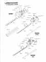
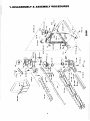
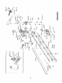
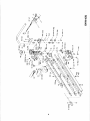
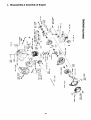
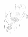
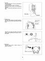
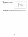
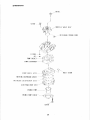
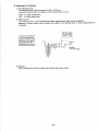
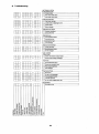
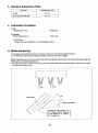
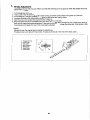
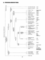
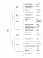
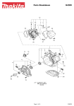
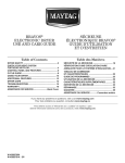
MODEL EH561/EH760
SERVICE MANUAL
.
1 SPECIFICATIONS
a. Designation of Parts . . . . . . . . . . . . . . . . . . . . . . . . . . . . . . . . . . . . . . . . . . . . . . . . . . . . .
b. Specifications
...........................................................
3
4
.
2 PREPARATIONS
a. Disassembly & Reassembly Procedure . . . . . . . . . . . . . . . . . . . . . . . . . . . . . . . . . . . . . .
5
b. Cautions
6
..............................................................
.
3 DISASSEMBLY 81ASSEMBLY PROCEDURES ...............................
7.
9
a. Removal of Engine and Machine Body . . . . . . . . . . . . . . . . . . . . . . . . . . . . . . . . . .
10 .
11
b. Disassembly & Assembly of Machine Body . . . . . . . . . . . . . . . . . . . . . . . . . . . . . .
12 .
13
c . Disassembly & Assembly of Engine
....................................
14 .
18
d. Disassembly & Assembly of Carburetor . . . . . . . . . . . . . . . . . . . . . . . . . . . . . . . . .
19 .
24
4 . CHECKUP AND ADJUSTMENT
a . Daily Checkup and Adjustment . . . . . . . . . . . . . . . . . . . . . . . . . . . . . . . . . . . . . . . . . . . .
25
b. Checkup and Adjustment for Every 30 - 50 Hours. (Every 10 Days) . . . . . . . . . . . . . . . 26
c. Checkup and Adjustment for Every 100 - 200 Hours. (Monthly) . . . . . . . . . . . . . . . . . . 26
.
5 STANDARD OF ADJUSTMENT
a. Tightening Torque of Components . . . . . . . . . . . . . . . . . . . . . . . . . . . . . . . . . . . . . . . . .
27
b. Standard Adjustment Table
28
...............................................
c. Lubrication Procedure . . . . . . . . . . . . . . . . . . . . . . . . . . . . . . . . . . . . . . . . . . . . . . . . . . .
d. Bladesharpening . . . . . . . . . . . . . . . . . . . . . . . . . . . . . . . . . . . . . . . . . . . . . . . . . . . . . . .
e. BladeAdjustment . . . . . . . . . . . . . . . . . . . . . . . . . . . . . . . . . . . . . . . . . . . . . . . . . . . . . . .
6. TROUBLESHOOTING
.................................................
2
30
28
28
29
- 31
1 SPECIFICATIONS
a. Designation of Parts
Fiirl lank rap
\
I
o switrtl (ONorr)
b. Specifications
I Model
EH760
EH561
Dimensions (L x W x H)
mm
1,041 x 280 x 258
840 x 246 x 225
Mass (with blade cover)
kg
5.8
5.8
Volume (fuel tank)
cm3
600
Engine displacement
cm3
21.7
Cutting length
mm
Maximum engine performance
kw
735
560
0.74
I Maximum blade speed
m/s
1
1.88
1
Idling speed
l/min
I
2,600
Clutch engagement speed
l/min
Carburetor type
type
WALBRO WYL
Ignition system
type
Solid ignition system
Spark plug
type
NGK-BMR7A
Electrode gap
mm
0.6 - 0.7
3,600
Mixture ratio (fuel: MAKITA 2-stroke oil)
50: 1
Gear ratio
14 : 58
1) The data takes equally into account idling and racing speed operating modes.
I
2. PREPARATIONS
a. Disassembly and Reassembly Procedures
The disassembly and reassembly procedures mentioned below are given as a general rule. These
procedures can be added to or omitted according to your operating conditions.
II. PREPARATIONS
Cleaning
Drainage of fuel
Disposition of tools
I
Ill. DISASSEMBLY
1. Machine body
2 Engine
Cleaning of parts
CHECKUP
Checking of parts
(Refer to IV. CHECKUP AND ADJUSTMENT)
(Refer to V. STANDARD OF ADJUSTMENT)
(Refer to X. SETTING OF BRUSH BLADE)
1
1. Engine
IV. REASSEMBLY
2 Machine body
(Refer to VIII. TABLE OF TIGHTENING TORQUE)
I
.
STARTING TEST
c
1. Starting procedure
2 Checkup and adjustment of carburetor
Checkup and adjustment
I
(Refer to IX. TROUBLESHOOTING)
NOTE: The numbers are the same as those in this manual.
5
b. Cautions
1) Preparations
(1) Workbench
(2) Disassembly and reassembly kits and gauges
(3) Washing bowl
(4) Rinse oil (light oil, gasoline, etc.)
(5) Oil (mobile oil), grease
(6) Adhesive, sealant
(7) File, sandpaper
(8) Shop cloth
2) Cautions in Disassembly
(1) Use standard tools correctly.
(2) Handle disassembled parts with care and be sure to clean them.
In particular, remove dust or dirt adhering to the mounting surfaces of packings.
Bearings in rod are easy to separate. If there is no abnormality on rod, no special maintenance is
needed without removing contaminated grease.
(3) Keep disassembled parts in order to avoid loss or error in reassembly.
(4) If it is hard to loosen bolts or screws, use an impact driver.
3) Cautions in Reassembly
(1) Pay attention to the combination of parts (in particular, mounting direction: front and rear, right and
left, upper and lower).
(2) Replace packings and gaskets with new ones.
(3) Tighten bolts and screws twice in a diagonal manner.
(4) Apply two-cycle engine oil (or Mobile oil) to rotary and sliding parts.
(5) During reassembly, be careful to keep parts free of dust and dirt.
(6) For rotating parts, turn them by hand to check for movement or noise.
(7) After reassembly, turn the rotating parts by hand and confirm that there is no abnormality (loosen-
ing, etc.)
(8) Never fail to apply genuine grease into case.
6
3. DISASSEMBLY & ASSEMBLY PROCEDURES
_
/
7
_
-
- \
8
I
9
a. Removal'of Engine and Machine Body
For EH561
1. StarVStop lead wire
Remove lead wire connecting rear-handle stop
switch with engine.
2. Throttle wire
Remove cable holder fixed to rear handle by
loosening screw (M4 x 10).
Remove throttle wire from throttle lever parts.
Cable h o l d e r
3. Engine
Remove engine by loosening two bolts (M6 x 15, PW, SW) with fixing case and engine and one bolt (M6 x 40,
W, SW) with combine rear handle with case and engine.
4. Rear handle
Loosen bolt (M6 x 50, W, SW) on case side and
remove rear handle.
5. Front handle
Loosen bolt (M6 x 35, SW) with fixing case and front handle and remove front handle.
10
For EH760
*
1. StarVStop lead wire
Remove lead wire connecting rear-handle stop
switch with engine.
2. Throttle wire
(For STD) Remove throttle wire form throttle lever.
(For CE) Remove throttle wire from carburetor.
3. Left handle
Loosening two bolts (M5 x 30)with handle holder.
4. Handle holder
Loosen two bolts (M6 x 35, W, SW) with engine.
5. Engine
Remove engine by loosening three bolts (M6 x 15, PW, SW) with fixing case and engine.
6. Right handle
Loosening two screws with Blade and remove right handle.
11
b. Disassembly 4% Assembly of Machine Body
Crank q e a r
Drum
.
\
U p p e r case
-Lower
ca5
Pinion qear /
1. Drum
Lock blade by tightening 3 blade slide screws to
the full. Then remove drum by using drum hole.
If drum can not be loosened, apply wood chip
under blade nearer at engine and remove drum
by using drum hole.
<Caution>
The screws are right-handed. Turn to the left in
loosening.
Be careful not to miss collar under drum.
2. Lower case
Remove 3 blade-fixing U-nuts first. Then loosen 7 bolts (5 M5 x 16 and 2 M5 x 20) and remove lower case.
It is advisable to remove lower case, tapping it with plastic hammer.
If it is hard to remove case, pry case with flat-headed screwdriver paying attention not to damage case or parts
inside case.
After mounting, temporality tighten 3 blade-fixing U nuts.
(Apply oil to sliding parts in proper amount.)
<Caution:,
This work must be done at a place as low as possible, as there is possibility that needles separate if rod is
detached together with case.
Be careful not to damage case contact surfaces.
Apply grease to rod and gear in proper amount.
12
3. Rod slide plate, Pinion gear, Felt
Loosen 2 screws (M3 x 5) and remove rod slide plate fixed under lower case.
Then remove pinion gear from upper case. If it is hard to remove, tap pinion with plastic hammer.
Then remove felt.
4. Rod
Remove rod on lower-blade side.
<Caution>
Before removing rod, apply a small amount of grease to needles and turn rod several times so that they will
not separate.
Keep in memory rod mounting direction.
Apply grease to crank and lower-blade rod shift and mount rod.
5. Lower/Upper blade
Loosen 3 blade-slide screws and remove lower blade.
<Caution>
Be careful not to miss blade slide washer.
Then remove upper blade.
6. Crank gear, Crank
Remove crank gear and crank from upper case. If it is hard to remove, tap case with plastic hammer.
Then loosen screws (M5 x 10) fixing crank gear and crank and remove crank.
<Caution>
Apply grease to upper case in proper amount.
Apply grease to crank gear and crank in proper quantity and mount them in upper.
7. Retainer plate, Grease nipple
Loosen flange nut and 2 screws (M5 x 16) and remove retainer plate. Then remove grease nipple.
c. Disassembly & Assembly of Engine
14
0
V
w
m
Q
u
-J
/
/
-I
0
t-a
Z
0
,/
i
a:
0
t-
W
a
3
m
a
cl
u
15
1. Fuel tube
Pull fuel tube about 20 - 30 mm out side fuel tank
for easy assembly.
Assemble fuel tube as shown in the figure.
Return fuel tube to within the tank following
assembly.
(with no bends that might prevent smooth fuel
flow)
2. Cylinder cover
Keep the muffler gasket and insulator gasket in
the correct position when assembling the cylinder
cover.
Insulator
Keep the cover spacer and washer in the correct
position when assembling the cylinder cover to
the cylinder.
3. Buffle plate
Assemble buffle plate to blower housing as
shown in the figure.
16
4. Clutch
Keep the washer in the correct position when assembling the clutch.
5. Ignition coil
Use thickness gauge to assure that the air gap will be 0.3 - 0.4 mm between the ignition coil and flywheel
magnet portion when installing the ignition coil.
6. Flywheel
Install the socket head bolt onto the crankshaft
and tighten them securely. Remove the flywheel
with a pulling tool as shown in the figure.
During assembly, be sure first that you have the
crankshaft key slot properly aligned with before
installing. Then check the key slot and flywheel
alignment indication.
7. Crankcase
When assembling the crankcase, cut off the
crankcase gasket sticking out from the cylinder
installing surface.
(See figure at right)
cutter blade
8. Cylinder
When assembling the cylinder, coat both the cylinder inner surface and the piston itself with 2-cycle engine oil.
17
9. Piston
When equipping the piston in the crankshaft
ass’y, the triangular mark ( A ) on the top of the
position should be on the crankshaft key slot side.
10. Piston ring
When installing the piston ring on the position, align the knock pin on the piston with the split on the piston ring.
Unless they are lined up the cylinder cannot be assembled.
18
d. Disassembly & Assembly of Carburetor
1) Function of Parts
19
(1) Throttle Valve
Controls engine output.
(2) Tamper Resistant Plug:
Prevents entry of air and foreign matter.
(3) Low-Speed Needle:
Regulates fuel at idling or slow rpm.
(4) Inlet Screen:
Filters fuel intake to carburetor.
(5) Needle Valve:
Controls fuel supply to metering chamber from fuel pump.
(6) Fuel Inlet:
For fuel intake.
(7) Metering Lever Spring:
Works together with metering diaphragm to ensure constant pressure
in metering chamber.
(8) Metering Lever:
Conveys operation of metering diaphragm to needle valve.
(9) Metering Diaphragm:
Works up or down depending on difference of pressure inside engine
and atmospheric pressure so as to open or close the needle valve
through the metering lever and metering spring.
(10) Metering Chamber:
Supplies fuel via nozzle by fuel tank.
(11) Fuel Pump Diaphragm:
Undulates, in keeping with engine pulse. This action serves to send fuel
to the diaphragm chamber.
(12) Fuel Outlet:
Allows excess fuel to return to the tank during primer pump operation.
(13) Engine Pulse:
Takes the negative or positive pressure building up in the crankcase
under piston operation and makes the fuel pump diaphragm work
accordingly.
(14) Main Jet:
Regulates fuel at high speed.
(15) Nozzle:
Outlet for fuel sent into the cylinder.
(16) Idle Adjust Screw:
Controls idling rpm.
(17) Primer Pump:
Brings fuel up from the fuel tank into the metering chamber.
(18) Combination Valve:
Acts as a check valve between primer pump intake and charge.
(19) Main Check Valve:
Prevents air in the nozzle from entering the metering chamber when
the primer pump is being worked.
(20) Outlet Valve:
Works just the opposite of the inlet valve.
(21) Inlet Valve:
Valve opens when diaphragm is subjected to negative pressure, and
closes under positive pressure, corresponding to the pump action.
20
2) Maintenance
PI11MLlI PIIMP -I’I1IMLTl I’UMP W L I I - -
21
A) DISASSEMBLY AND ASSEMBLY PROCEDURE
1) Refer to the disassembly drawing when disassembling or assembling.
2) Be careful not to damage gaskets and the like when assembling
3) Do not attempt to disassemble the throttle valve ass’y or pump body ass’y.
4) When you find during disassembly of the carburetor that the inlet screen is clogged or there is considerable dirt buildup in the carburetor itself, be sure to clean out the fuel tank and replace the fuel tank
filter.
B) INSPECTION PROCEDURE
1) Clean off the tool body and dry off with an air nozzle.
2) Check for dirt adhering to the main jet or corrosion. Blow off any dirt with an air nozzle.
3) Be sure gaskets and the like are not damaged or deformed. Replace as necessary.
4) Check for damage or hardening of the pump diaphragm. Be sure inlet and outlet valves are horizontal and
not bent.
5) Check for possible damage or hardening of the metering diaphragm. The plate should not be sent.
6) Check for bending or damage to the pump plate.
7) After cleaning the pump body ass’y, check spring deformation, lever height, inlet screen (for dirt clogging
it), valve operation, etc. When inspecting check valve operation, look for blockage due to dirt at the check
valve portion or vinyl pipe by blowing through the port. If blocked, replace.
CAUTION: Never blow air into the check valve under high pressure.
8) Check for possible deformation of the air purge body, combination valve, etc.
9) Lock for holes, damage or hardening of the primer pump.
22
3) Adjustment of Carburetor
(1) Idle adjusting screw
The standard idling rotational speed is 2,500 - 2,700 rpm.
Adjust the speed as high as possible so that the blade does not turn.
Right : for higher speed (rpm)
Left : for lower speed (rpm)
(2) Metering lever
The metering lever is a very important part. Never tamper with it under normal conditions.
Measure as shown below, when checking the height of the metering lever or when measurement is
necessary.
Standard height:
1.5 0.15 mm
*
The fuel is rich when the
end of the control lever
goes up as shown in the
solid line in the drawing,
and is lean when the
dotted line goes down in
the direction of the arrow.
*
(0.059 0.006")
carburetor body
(3) Main jet
When replacing the main jet, always use one with the same number.
23
4) Troubleshooting
METERING SYSTEM
Inlet Needle 8 Seat
I O I Foreian matter
Io I
Wom inlet needle valve
I Inlet needle valve stuck
I
Metering Diaphragm
I0 I
Io I
I 0I
0I
Diaphragm damage
Loose screw on diaDhraam cover
Gasket defect
I
I
I
Button damage
Metering Lever Spring
BEl
0 Improper installation
000
Lever set too low
Lever set too high
0
0 0
0 Leverdamage
CIRCULATION SYSTEM
Loose carburetor
Io I
00
0
0
0
0
Manifold gasket failure
0
Check valve failure (foreign matter)
I 0I
PumD diaDhraam failure
1
I
Pump cover screw(s) loose
0
Io I
Pulse leakage
I
Fuel Tank 8 Pumo
Io I
I 0I
0
0
0
Wrong fuel
Air leak in fuel Dassaaes
Fuel passages blocked
Tank filter jammed
Air vent holes clogged (tank cap)
IUSTMENT
Idle adjust screw
I
I
4. CHECKUP AND ADJUSTMENT
a. Daily Checkup and Adjustment
1.
Aspect
Confirm that there is no damage or wear.
2. Bolts, nuts, damper pin
Check bolts and nuts for damage, wear or tightening.
Retighten if necessary.
3. Safety cover
Check safety cover for damage or loosening.
Confirm that the safety cover is mounted in contact with gearcase.
4. Trimmer blade
Confirm that Trimmer blade is set correctly.
Checkup Trimmer blade for chipping, crack or bend.
Replace if necessary.
5. Handle
Confirm that handle-fixing bolt is fastened securely.
6. Cleaning of dirt, dust or saw dust
1) Crankcase
If there is any dust or dirt adhering to cooling air inlet, fan cover-cylinder fins, etc. of rear crankcase,
disassemble them and remove dust or dirt.
2) Cylinder
If there is any dust or dirt adhering to cylinder fin, detach cylinder cover and remove it.
7. Throttle lever
Confirm that throttle lever can be operated smoothly.
Can engine be operated from low speed to high speed?
8 . Stop button
Confirm that stop button can be operated smoothly.
Can engine be stopped without fail?
9. Muffler, Muffler cover
Check muffler and muffler cover for damage or loosening.
Remove carbon in muffler if present.
10. Operating and rotating parts
Check operating parts for abnormality and rotating parts for abnormal noise.
25
b. Checkup and Adjustment for Every 30 - 50 Hours (Every 10 Days)
1. Air cleaner
Remove cover of air cleaner and cleaner filter inside with gasoline.
After wringing, fit it to air cleaner.
2. Spark plug
If spark plug is damaged or becomes dirty, clean it well with gasoline or sand it with sandpaper so as to adjust
spark gap to 0.6 - 0.7 mm.
0.6- 0.7 mm
(0.024- 0.028”)
c. Checkup and Adjustment for Every 100 - 200 Hours (Monthly)
1. Cleaning and adjustment of carburetor
Clean diaphragm, throttle, etc. of carburetor with gasoline.
Refer to description on idling adjustment and fuel adjustment.
2. Fuel tank filter
Clean dust or dirt inside fuel tank with gasoline.
Clean tank inside. Replace filter if filter screen inside felt is clogged.
3. Muffler
Remove muffler. Remove carbon adhering to muffler, cylinder exhaust port and tail pipe.
4. Clutch shoe
Remove clutch bolt and detach clutch shoe from holder.
Apply grease to inside of shoe-mounting hole and clutch bolt and mount them.
5. Replacement
1) Replace cleaner element.
2) Replace spark plug.
26
4. STANDARD ADJUSTMENT
a. Tightening Torque of Components
Main Body
1
1
Tightening Part
I
Tightening Torque
(kg. cm)
Grease nipple
35 f 5
Retainer plate
40
!z
50
*5
I
Screw
(Diam. x Length)
Remarks
* Screw
M 5 x 16
Flange nut
M5
Screw
I
Crankgear
I
50 f 5
I
M5x 10
I
Screw
I
Rod slide plate
I
15f3
I
M3 x 15
I
screw
I
Lowercase
I
45
I
M5x16,M5x20
I
Screw
5
Blade fixing U nut
8 0 i 10
Drum
170
Front case
50 f 5
Upper case
I
I
f
Cable holder
Rear handle main unit
I
I
I
I
* 20
M6
U nut
M10
-
M6 x 30
I
I
I
I
75 f 5
50 f 5
8-13
8 - 13
M6x15
M6 x 40
M 4 x 10
M4x16,M4x30
Bolt
I
I
1
I
Bolt
Bolt
Screw
Screw
Use quick-set bonding adhesive.
Engine
Tightening Torque
(kg ' cm)
Tightening Part
Screw
(Diam. x Length)
Remarks
Crankcase
45 f 5
M5 x 25
Screw
Cylinder
80f 10
M5 x 20
Socket head bolt
Flywheel
100 f 10
M6 x 16
Bolt
Ignition coil
25 f 5
M4 x 20
Screw
Spark plug
150 f 3
M14
75 i5
M5 x 50
45 f 5
M5 x 25
Screw
Carburetor
25 f 5
M5 x 65
Screw
Blower housing
45 f 5
M5 x 16
Screw
Recoil starter
15 - 20
M5 x 14
Screw (Black)
Cylinder cover
30 f 5
M5 x 14
Screw (Black)
Muffler cover
40 f 5
M 5 x 16
Screw
Tank plate
45
5
M 5x 16
Screw
Fuel tank
45 f 5
M5 x 16
Screw
Muffler
Insulator
f
NGK-BMR7A
* Socket head bolt
I
Clutch
I
90f 10
I
M6 x 25
I
Bolt
I
Holder
I
7 5 f 10
I
M6 x 14
I
Bolt
Use quick-set bonding adhesive.
27
b. Standard Adjustment Table
I
Test Parts
I
I
Air gap
Spark plug electrodes gap
I
I
I
Standard Size (mm)
0.3 - 0.4
0.6 - 0.7
I
I
I
c. Lubrication Procedure
1) Oil
Mobile Oil No. 30.
......................
.Throttle wire
2) Grease
Shell Albania No. 3 .......................
.Gear case
<CAUTION>
Always use above oiVgrease or a comparable product.
d. Blade sharpening
If the edges are rounded and do not cut well any more, find off only the shaded portions.
Do not find the contact surface (sliding surfaces) of the top and bottom edges.
Before grinding, be sure to secure the blade firmly and switch off the engine and remove the spark plug cap.
Wear gloves, protective glasses, etc.
An edges ground too much at a time or ground many times will lose its hardened layer. It becomes rounded
and dull very quickly in use.
\
the rounded tip.
28
I
e. Blade Adjustment
The blades will wear with long use. When you find that trimming is not as good as when the blades were new,
adjust them as follows.
1. Turn Hexagonal U nut loose.
2. Truss screw in with the driver lightly till it stops turning, and then screw it back one quarter to a half turn.
3.Turn Hexagonal U nut tight, holding Truss screw at the same time with a driver.
4. Lubricate the blades after adjustments above with light oil.
5. Start the engine and operate the engine throttle on and off for a minutes.
6. Stop the engine and touch the blades with your hand. If they are warm enough for you to keep your hand on,
then you have made the proper adjustment. If they are too hot for you to keep touching, give Truss screw, a little
more turnback and repeat 5 to see if the are properly adjusted.
<NOTE>
Never fail to stop the engine before making the adjustment.
The blades have a slot around Truss screw. In case you find dust in the end of the slots, clean it.
0 Hexagonal U nut
Trussscrew
@ Flat washer
@ Blunt extension
0 Blade guide
@ Upper Blade
0 Lower blade
29
6. TROUBLESHOOTING
Y
C
2
V
e --
c
Abnormality inside engine
. . . Check
0)
.-c
c
ln
a
0
Malfunction of carburetor . . . . Check
0a.0
%
.G
a).
U
a
C
.cn
c
a v
W
with coil
.
I
-
0-0
.cL
b
c v
Defective coil
~
a2
2;
. . . . . . . . . . . . .Replace
- Stop switch is grounded . . . . . Replace
~
- Defective wiring . . . . . . . . . . . Correct
5+g
2%
.........
r
Defective or damaged
spark
plug
.
.
- . . . . . . . . . . . . . . . Replace
t
-maP
c
m
Incorrect spark plug gap
. . . . Adjust
Adherence of carbon . . . . . . . Clean with
brush
-E
Spark plug too damp . . . . . . .Dry
I
Incorrect connection of
spark plug gap . . . . . . . . . . . .Correct
Felt is clogged with dust . . . . . Replace
- Fuel does not
Air orifice of tank cap
isclogged . . . . . . . . . . . . . . . . Clean
keep running
Fuel passage in carburetor
is clogged with dust . . . . . . . .Clean
IDefective
-acceleration
function
Leakage from mounting
surface of carburetor . . . . . . . Retighten
Air orifice of fuel tank cap
is clogged . . . . . . . . . . . . . . . .Clean
L---.-
-a
Pressure leaks . . . . . . . . . . . . Stop
leakage
(packing, etc.)
3
.
I
-
Clogged needle valve
at fuel inlet . . . . . . . . . . . . . . .Clean
-Overflow
Adjusted metering lever
. . . . . Correct
Fuel different from
specified one . . . . . . . . . . . . . Replace
Incorrect opening of
throttle lever and choke
lever ....................
Fuel too lean or rich
Operate regularly
. . . . . . . . Adjust
Fuel overflows into . . . . . . . . Clear needle
muffler
valve of dust and
start with throttle
lever fully opened
cn
.-C
!f
C L
-I
28
z"
Tank, felt clogged . . . . . . . . . . Replace
Fuel pipe clogged . . . . . . . . . . Clean
Air mixed in fuel pipe . . . . . . . Drain air
No fuel in tank
30
,
-
Inadequatefuel used . . . . . . . . . . . . . . . . . . Use specified fuel
- Defective plug (overheated) . . . . . . . . . . . . Replace
-
-Overheated
engine
Air ventilation hamperedbecause
of cylinder clogged with dust . . . . . . . . . . . . Clean
(Inlet of cooling air, fan cover,
fan, cylinder fin)
- Carbon adhering to combustion
chamber . . . . . . . . . . . . . . . . . . . . . . . . . . . .
Overhaul, clean
- Fuel is too lean . . . . . . . . . . . . . . . . . . . . . .
Overhaul, clean
- Too much load to cutter blade . . . . . . . . . . . Lessen load
Damaged or fouled spark plug
or inadequatespark gap . . . . . . . . . . . . . . . Replace, clean,
adjust
Defective
-ignition
function
Irregular adjustmentof low-speed
fuel adjusting screws . . . . . . . . . . . . . . . . . Adjust
Clean
-Defective
Carburetor
Overflow . . . . . . . . . . . . . . . . . . . . . . . . . . .
Refer to indication
in previous page.
Fouled air cleaner . . . . . . . . . . . . . . . . . . . .
Clean
Damaged diaphragm membrane . . . . . . . . . Replace
Engine
runs but__
Poor
RPM’s
r
-Other causes
-Blade does not
cut well
Ineffective compression . . . . . . . . . . . . . . . . Overhaul, check
and replace
(mis-contact and wear of piston ring)
(gas leakage from cylinder and crankcase)
(Insufficienttightening of spark plug) . . . . . . Retighten
Exhaust port clogged with carbon . . . . . . . . Clean
Throffle valve not fully opened . . . . . . . . . . . Open fully
Clogged tank filter . . . . . . . . . . . . . . . . . . . .
Replace
Polished cutter blade . . . . . . . . . . . . .
Polish correctly
I
Slippage of cutter blade . . . . . . . . . . . . . . . . Tighten correctly
-Blade
fluctuates ____-
c
Worn or damage rod shaft hole . . . . . . . . . . Replace
Worn blade-fixing screw . . . . . . . . . . . . . . . Replace
Ft
Excessive load on cutter blade . . . . . . . . . . Lessen load
Worn clutch shoe . . . . . . . . . . . . . . . . . . . . .
-Blade
stops ___
Overhaul, replace
Excessive tightened blade fixing screw . . . . Mount correctly
Damaged small gear or crankgear . . . . . . . Replace
Damage centrifugal clutch . . . . . . . . . . . . . . Replace
i
Damage drum . . . . . . . . . . . . . . . . . . . . . . .
-Blade cannot
be actuated
Replace
Damage small gear on crankgear . . . . . . . . Replace
Damaged blade rod shaft
31
. . . . . . . . . . . . . . Replace