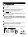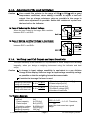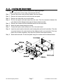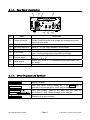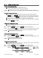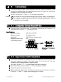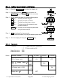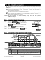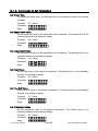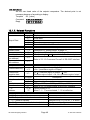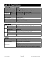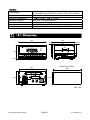
1
Weighing Indicator
1WMPD4002801
This is a hazard alert mark.
This mark informs you about the operation of the product.
Note
This manual is subject to change without notice at any time to improve the product.
No part of this manual may be photocopied, reproduced, or translated into another
language without the prior written consent of A&D Company, Ltd.
Product specifications are subject to change without any obligation on the part of the
manufacture.
© 2013 A&D Company Ltd. All rights reserved.
Contents
1.
Compliance ............................................................................ 3
1.1.1.
Compliance with FCC Rules ............................................................. 3
1.1.2.
Compliance with European Directive ................................................ 3
2.
Introduction ........................................................................... 4
3.
Installation and Precautions ................................................... 5
3.1.1.
Installation and Precautions............................................................. 5
3.1.3.
Adjustment of the Load Cell Output................................................. 6
3.1.2.
3.1.4.
3.1.5.
4.
4.1.1.
4.1.3.
4.1.4.
Installing the Option Board .............................................................. 7
Front Panel Description ................................................................... 8
Rear Panel Description..................................................................... 9
Other Displays and Symbols ............................................................ 9
Accessories and Option OP-02 ...................................................... 10
Calibration ........................................................................... 11
5.1.1.
5.2.
5.2.1.
5.2.2.
5.2.3.
Items of Calibration Mode.............................................................. 11
Calibration Procedure................................................................12
The Whole Procedure..................................................................... 12
Preparation.................................................................................... 13
Entering the Calibration Mode ....................................................... 13
5.2.4.
Minimum Division (Weighing Interval) ............................................ 14
5.2.6.
Zero Calibration ............................................................................ 15
5.2.8.
Exiting the Calibration Mode.......................................................... 17
5.2.5.
5.2.7.
Maximum Capacity ........................................................................ 14
Span Calibration ............................................................................ 16
5.3.
Weighing Range Function ..........................................................18
5.4.
Digital Linearization Function ......................................................22
5.5.
Gravity Compensation Function ...................................................23
5.6.
Calibration Error Code List ..........................................................25
5.3.1.
5.5.1.
6.
Verifying Load Cell Output and Input Sensitivity............................... 6
Description of Panels and symbols ......................................... 8
4.1.2.
5.
The Load Cell Connections .............................................................. 5
6.1.
Setting Division and Range ............................................................ 19
The Gravity Acceleration Table....................................................... 24
Functions ............................................................................. 26
Changing the Function Settings ...................................................26
6.2.
F-Functions ...............................................................................27
6.3.
CF-Functions .............................................................................32
AD4329A Weighing Indicator, Instruction Manual, A&D Co., ltd.
Page 1
7.
Tare ..................................................................................... 33
7.1.1.
Weighing Tare ............................................................................... 33
7.1.2.
Digital Input .................................................................................. 33
7.1.3.
8.
Accumulation ....................................................................... 34
8.1.1.
8.1.2.
9.
Clearing Tare................................................................................. 33
9.1.
Preparation and Specification......................................................... 34
Display and Operation ................................................................... 35
Comparison ......................................................................... 36
Comparator Output Relay (OP-02) ...............................................36
9.2.
9.2.1.
Upper/Lower Limit Comparison..................................................36
Selecting Upper/Lower Limit Comparison........................................ 37
9.2.2.
Condition formula for Comparison ................................................ 37
9.2.4.
Example ........................................................................................ 38
9.2.3.
9.3.
9.3.1.
9.3.2.
9.3.3.
Setting Upper/Lower Limit Values .................................................. 38
Setpoint Comparison.................................................................39
Selecting Setpoint Comparison ...................................................... 39
Description of Input parameters and Outputs ................................ 39
Setting the Parameters of Setpoint Comparison ............................. 40
10.
External Control Input .......................................................... 41
11.
Standard Serial Data Output (SER.OUT) ................................. 42
12.
11.1.1.
RS-232C Interface................................................................ 44
12.1.1.
Specification.................................................................................. 44
12.1.2.
Data Format .................................................................................. 45
12.1.4.
Command to Request Data ............................................................ 46
12.1.5.
Commands to Control the Indicator ............................................... 47
12.1.7.
Related Functions .......................................................................... 49
12.1.3.
12.1.6.
13.
Data Format .................................................................................. 43
13.1.
Command Format.......................................................................... 46
Commands to Set Parameters ........................................................ 48
Specifications ....................................................................... 50
Dimensions...............................................................................51
Page 2
AD-4329A Weighing Indicator
1.
1.1.1.
Compliance
Compliance with FCC Rules
Please note that this equipment generates, uses and can radiate radio frequency
energy. This equipment has been tested and has been found to comply with the
limits of a Class A computing device pursuant to Subpart J of Part 15 of FCC rules.
These rules are designed to provide reasonable protection against interference
when this equipment is operated in a commercial environment. If this unit is
operated in a residential area it may cause some interference and under these
circumstances the user would be required to take, at his own expense, whatever
measures are necessary to eliminate the interference.
(FCC = Federal Communications Commission in the U.S.A.)
1.1.2.
Compliance with European Directive
This appliance complies with the statutory EMC (Electromagnetic Compatibility)
directive 2004/108/EC and the Low Voltage Directive 2006/95/EC for safety of
electrical equipment designed for certain voltages.
Note: The displayed value may be adversely affected under extreme electromagnetic
influences.
AD-4329A Weighing Indicator
Page 3
1. Compliance
2.
Introduction
The AD-4329A is a compact weighing indicator that amplifies the signal from a load
cell, converts it to digital data and displays it as a mass value.
This indicator has the following performance:
Input sensitivity: ......................... 0.15 µV/division.
Maximum display: ...................... 10000 divisions (or 20000 divisions).
Refresh rate of the display: ........ 10 times/second approximately.
Input voltage range: ................... -35 mV ~ +35 mV.
There are the following standard functions:
The upper/lower limit comparison to check a mass value.
The setpoint comparison for batching applications.
The accumulation function to totalize these mass values and to count the
number of accumulations.
There are the following standard interfaces:
The standard serial output for a printer.
The RS-232C serial interface to communicate with a computer.
This interface can request weighing data, enter parameters and control the state
of the indicator.
The calibration function includes the following functions:
Setting of the minimum division (weighing interval) and the maximum capacity.
Zero and span calibration.
The weighing range function of the multi-interval weighing instrument (scale).
Digital linearization function.
Gravity compensation function.
There are seven external input terminals controlled by the F function.
The option OP-02 has three output relays used for the upper/lower limit comparison
and setpoint comparison.
2. Introduction
Page 4
AD-4329A Weighing Indicator
3.
3.1.1.
Installation and Precautions
Installation and Precautions
The AD-4329A weighing indicator is a precision electronic instrument. Handle the
indicator carefully.
The operating temperature is -10 to +40 (14 to 104 ).
Do not install the scale in direct sunlight.
Misoperation or other problems may be caused by an unstable power source including
momentary power failrue or instantaneous noise. Use a stable power source.
Do not connect the power cord before the installation is finished.
Please confirm that the local voltage and receptacle type are correct for your scale.
The Operate/Standby key (
key) can not cut the power. The load cell and the internal
circuit are supplied with power in the standby state.
Use shielded cable for all connections. Connect the cable shields to the shield
terminal or case as an earth terminal.
Earth ground the indicator. Do not join the earth ground line with other electric
power equipment. There is an earth ground terminal at the power cord receptacle.
Do not install the scale in a place where it is apt to be charged with static electricity,
or where the relative humidity is lower than 45%RH. Plastic and isolators are apt to
be charged with static electricity.
3.1.2.
The Load Cell Connections
Connect the load cell wires to the connector (receptacle), at the rear panel, using
the accessory load cell plug.
It is possible to connect a 4 wire cable that 1pin-2pin and 3pin-4pin are shorted, if
the distance between the indicator and a load cell is shorter than 5m.
The output voltage of a load cell is a very sensitive signal. Space the load cell cable
away from any noise source.
It is possible to connect eight 350Ω load cells.
The load cell drive is 5VDC 5% between EXC+ and EXC-, the maximum current
120mA.
AD-4329A Weighing Indicator
Page 5
3. Installation and Precaution
3.1.3.
Adjustment of the Load Cell Output
Caution
Use a metal film resistor in the range of 50kΩ to 500kΩ with a good
temperature coefficient, when adding a resistor to adjust a load cell
output. Use as a large resistance value as possible in the range in
which zero adjustment is possible. Solder this resistor at a point near
the load cell or the indicator.
In Case of Reducing the Output Voltage
When the zero output is too large, add a resistor
between EXC+ and SIG-.
In Case of Adding an Offset Voltage to the Output
When the zero output is too small, add a resistor
between EXC+ and SIG+.
3.1.4.
Verifying Load Cell Output and Input Sensitivity
The input sensitivity of the indicator is 0.15μV/division or more. Adapt to the following
inequality, when you design a weighing instrument using the indicator and load
cell(s).
Caution
A change in input voltage sensitivity is equivalent to a one division
change of the display. Select as large an input voltage sensitivity voltage
as possible so that the weighing interval becomes stable.
Consider the leverage if a lever is used.
E ∗B ∗D
Weighing instrument
0.15 ≤
using one load cell.
A
E ∗B ∗D
Weighing instrument
0.15 ≤
using multi-load cell
A ∗N
Verification Example
Design:
Load cell
Rated capacity
Rated output
Excitation voltage
Weighing interval
Weighing capacity
3. Installation and Precaution
N=1
A=750 [kg]
B=3 [mV/V]
E=5000 [mV]
D=0.05 [kg]
300 [kg]
Page 6
A: Rated capacity of load cell [kg]
B: Rated output [mV/V]
D: Weighing interval [kg]
E: Excitation voltage [mV]
N: Number of load cells
5000 ∗ 3 ∗ 0.05
= 1 ≥ 0.15 . Therefore,
750
regard the instrument as a good
design.
AD-4329A Weighing Indicator
3.1.5.
Installing the Option Board
Caution
Do not remove screws without the following steps.
This is a procedure for the relay output board (OP-02).
Step 1 Remove the power cord and other cables from the indicator.
Step 2 Remove four screws and four bolts from the rear panel.
Step 3 Remove two slide-rails, one on each sides.
Step 4 Pull the rear panel and main board from the case. Then the connector between the
main board and the display board may be disconnected smoothly.
Step 5 Remove two screws and the small blank panel from the rear panel.
Step 6 Attach the option board using two screws.
Step 7 Connect the option cable connector to J5 on the main board.
Step 8 Insert the main board into the both main board guides and insert it as before. Then the
connector between the main board and the display board is re-connected. If the rear
panel will not close completely, retry step 8 to insert the main board correctly.
Step 9 Attach both slide-rails. Fix the rear panel using four screws and four bolts as before.
AD-4329A Weighing Indicator
Page 7
3. Installation and Precaution
4.
4.1.1.
Description of Panels and symbols
Front Panel Description
1
2
3
3
4
5
6
No.
Name
1
Standby indicator
2
3
Data display
Weighing unit
4
State indicator
5
CAL cover
6
CAL key
7
8
Operate/Standby key
Preset tare key
9
M+ (Accumulation) key
10
Mode key
11
12
13
14
Net/Gross key
+/- key
Zero key
key
Tare key
key
Print key
Enter key,
key
7
8 9 10 11 12 13 14
Description
The indicator lights at the standby state. This state means
connecting the power cord and turning the display off.
Weighing data is displayed.
A unit selected in the CF functions.
The
marks indicate kind of data and weighing state.
M+
It lights when there is accumulation data.
It is blinking when displaying accumulation data.
MD
The motion detection mark.
It lights when motion is detected.
It turns off while data is stabilized.
GROSS It lights when displaying gross data.
NET
It lights when displaying net data.
PT
It lights while entering a preset tare parameter.
ZERO It lights when displaying zero.
Calibration protection cover.
Calibration key. The key to adjust the scale so that mass
value is displayed correctly and to enter the CF functions.
The key to turn the display on or off.
The key to enter preset tare setting mode.
The key for the accumulation function.
Refer to "8. Accumulation", CF11, F4 and F5.
The key for the accumulation function and calibration.
The key to select a unit of lb or kg.
The key to select net or gross.
The key to set the polarity of data while in the setting mode.
The key to zero a current display.
The key to select a figure while in the setting mode.
The key to perform tare.
The key to select a value while in the setting mode.
The key to output data.
The key to store current data while in the setting mode.
4. Description of Panels and symbols
Page 8
AD-4329A Weighing Indicator
4.1.2.
Rear Panel Description
15
16
19
No.
Name
15
Power connector
16
17
18
Grounding terminal
RS-232C interface
Blank panel
19
Fuse holder
20
External input
21
Serial output
22
Load cell connector
4.1.3.
17
20
18
21
22
Description
Use accessory power cord.
Please Confirm that the local voltage and receptacle type are
correct for your scale.
Refer to "12. RS-232C Interface" for the detail.
Option space ( for relay output).
Use 0.5A time lag fuse for AC100V to AC120V.
Use 0.315A time lag fuse for AC200V to AC240V.
Seven control inputs selected function by the F functions.
Refer to F10 to 16.
Printer port. Refer to "11. Standard Serial Data Output" for
the details.
Connect accessory load cell plug.
Other Displays and Symbols
Standby display.
Zero error when turning display on. If the MODE key is
pressed, a current weighing value may be displayed.
Over load display. Remove any load from the load cell
immediately. It may cause damage to the indicator.
Example of an error display.
AD-4329A Weighing Indicator
Page 9
4. Description of Panels and symbols
4.1.4.
Accessories and Option OP-02
Accessories
Caution
Instruction manual
Load cell plug
Power cord
7pin Din connector
8pin Din connector
0.5A or 0.315A time lag fuse
1
1
(1)
1
1
1
Rubber foot
4
JM-NJC-207-PF
JA-TCP0576
JA-TCP0586
FS-EAWK-500MA
FS-EAWK-315MA
10-SJ-5023
Please Confirm that the receptacle type and local voltage is correct for
your indicator (scale).
Comparator relay output
Accessory
4. Description of Panels and symbols
OP-02
Cable
AD4329A-02
1
Page 10
AD-4329A Weighing Indicator
5.
Calibration
This weighing indicator, converts an input voltage from a load cell to the "mass"
value, and displays it. Calibration is the adjustment function so that the scale
(indicator) can weigh correctly.
5.1.1.
Items of Calibration Mode
There are seven items in the calibration function.
Basic Items
The minimum division ............... Setting the weighing interval.
The maximum capacity ............. Setting the maximum display.
Zero calibration.......................... When unloading any weight on the weighing unit
( there is nothing on the weighing pan), this function
performs adjustment so as to display the zero point
mark . Select an adjustment method from the
"weighing input" or "digital input".
Comment This function is the fundamental starting point to
weigh anything, and influences the performance of
scale (indicator).
Span calibration......................... The function to measure an input voltage variation by
loading to the weighing unit correctly. Select an
adjustment method from the "weighing arbitrary
mass", "weighing capacity mass" or "digital input".
Optional Items (Sub-functions)
Range function............................ The function for a multi-interval scale. Select "dual
range scale" or "triple range scale". Each range
has parameters of "weighing range" and "division"
Digital linearization function........ The function to revise a linearity deviation using
weighing points. (up to three weighing points)
Gravity compensation function... The function to revise weighing error between the
calibration location and another weighing location
using gravity acceleration.
Caution
The maximum display is less than or equal to 10000 divisions. This number
is calculated from the maximum capacity divided by the minimum division.
Check the accuracy of weighing instrument periodically.
Recommended mass, use a mass heavier than 2/3 maximum capacity.
AD-4329A Weighing Indicator
Page 11
5. Calibration
Calibrate the scale, if it is moved to another location or the environment
has changed.
It is not necessary to set the gravity acceleration correction, when calibrating
the scale with a calibration mass at the place where the scale is used.
Enter the stable weighing data while the MD mark is turned off. If
unstable data is used, it may cause a weighing error. Arrange the
condition using the F00 filter function.
The span calibration needs the zero calibration data. We recommend
that you perform the span calibration immediately after the zero
calibration.
Perform the digital linearization function immediately after the zero
calibration. And perform the span calibration continuously.
Select a decimal point and weighing unit at the CF function CF00, CF 01.
If you use the dual or triple range function of the multi-interval scale,
perform the "Range Function", "Zero Calibration" and "Span Calibration".
5.2. Calibration Procedure
5.2.1.
The Whole Procedure
Essential Items
Step A Preparation for calibration.
Step B
Step C
Step E
Step G
Minimum division.
Maximum capacity.
Zero calibration.
Span calibration
Optional Items
Step D Weighing range function.
Perform this function just
before zero calibration and
span calibration.
Step F Digital linearization function.
Perform this function after the
zero calibration immediately.
And perform the span
calibration continuously.
5. Calibration
Page 12
AD-4329A Weighing Indicator
Step H Gravity compensation function.
Perform this function after span calibration.
5.2.2.
Preparation
Step 1 Keep the following conditions to calibrate the scale (indicator) correctly.
Maintain a constant temperature, stable power and stable input voltage from the
load cell.
Avoid direct sunshine and in the neighborhood of an air conditioner.
Do not install the scale (indicator) where there is a strong magnetic field.
Step 2 Turn the display on during 10 minutes.
5.2.3.
Entering the Calibration Mode
Step 3 Press the CAL key in the normal weighing mode. The Cal in
is displayed for
two seconds when entering the calibration mode.
MODE key .. Parameters are not revised and the next item is displayed.
CAL key ..... Parameters are stored in the indicator and
end
is displayed.
Press the Operate/Standby key to turn the display off.
Press and hold the NET/GROSS key and press the CAL key
.................... All parameters are not changed
and the calibration mode is
finished. Press the Operate/Standby
key to turn the display off after
displaying CanCel .
AD-4329A Weighing Indicator
Page 13
5. Calibration
5.2.4.
Minimum Division (Weighing Interval)
Step 4 Check the d-xx display. The xx is minimum division (01, 02, 05, 10, 20, 50).
Step 5 Select a minimum division using the following keys.
key ....... The key to select a parameter.
key....... The key to store a parameter and
proceed to step 6.
MODE key... The key not to change a parameter
and proceed to step 6.
M+ key ...... The key to proceed to "5.5. Gravity
Compensation Function".
5.2.5.
Maximum Capacity
Step 6 Check the Cxxxx display. The xxxx is current
capacity. Select a new maximum capacity
using the following keys.
key...........The key to select a figure.
key ...........The key to select a number.
key...........The key to store a parameter
and proceed to step 7 (of the
zero calibration).
MODE key ......The key not to change a
parameter and proceed to step
7 (of the zero calibration).
PRESET TARE key .... The key to porceed to "5.3.
Weighing Range Function".
5. Calibration
Page 14
AD-4329A Weighing Indicator
5.2.6.
Zero Calibration
Step 7 Check the Cal 0 display.
Select a zero calibration method to adjust the zero point
The adjustment method
Weighing input
with nothing on the
To step 8
(Normal way)
weighing unit.
The numerical input to
Digital input
enter a load cell output To step 9
voltage.
Weighing Input
Step 8 Place nothing on the weighing unit. Press the
key
after the MD mark has turned off. Proceed to step10.
MODE key..... The key not to change the zero point
data and proceed to step 10.
Caution Do not press the
key while the MD mark is lit
(detecting motion). Arrange the condition using
the F00 filter function.
Digital Input
Step 9 Pressing the M+ key, a stored input voltage parameter
of the zero point is displayed in the unit of mV/V. Adjust
the input voltage using the following keys.
key ........ The key to select a figure.
key ........ The key to select a number.
key ........ The key to store the zero point parameter
and proceed to step 10.
MODE key... The key not to change parameter and
proceed to step 10.
AD-4329A Weighing Indicator
Page 15
5. Calibration
5.2.7.
Span Calibration
Step10 Check the fxxxx display. The xxxx is a capacity.
Select a span calibration method to adjust the capacity.
Weighing a mass except the
The method to weigh a mass except
maximum capacity
the maximum capacity.
The method to weigh a mass
Weighing maximum capacity
equivalent to the maximum capacity.
The numerical input to enter a load
Digital input
cell output voltage.
To step 11
To step 14
To step 16
Weighing a Mass except the Maximum Capacity
Step11 Set a mass value using the follwing keys.
key .... Key to select a figure.
key .... Key to select a number.
Step12 Place a mass equivalent to displayed value on the
weighing unit.
Step13 Press the
key after the MD mark turns off.
Proceed to step 17.
MODE key .... The key not to change parameter
and go back to step 4.
CAL key ....... The key not to change parameter
and proceed to step 17.
key while the MD mark
Caution Do not press the
is lit (detecting motion). Arrange the condition
using the F00 filter function.
Weighing Capacity Mass
Step14 Place a mass equivalent to the maximum capacity on
weighing unit.
Step15 Press the
key after the MD mark turns off.
Proceed to step 17.
MODE key .... The key not to change parameter
and go back to step 4.
CAL key ....... The key not to change parameter
and proceed to step 17.
Caution Do not press the
key while the MD mark
is lit (detecting motion). Arrange the condition
using the F00 filter function.
5. Calibration
Page 16
AD-4329A Weighing Indicator
From last page, B
From last page, C
From step10
Digital Input
Step16 Pressing the M+ key, a stored input voltage
parameter of the span is displayed in the unit
of mV/V. Adjust the input voltage using the
following keys.
key ........ The key to select a figure.
key ........ The key to select a number.
key ........ The key to store the span parameter
and proceed to step 17.
MODE key .. The key not to change parameter
From step13
From step15
Stored input voltage
mV/V
mV/V
New input voltage
and go back to step 4.
CAL key...... The key not to change parameter
and proceed to step 17.
5.2.8.
Exiting the Calibration Mode
Step17 Check the Cal end display.
Use the following keys.
CAL key ..... Parameters are stored in the indicator
and end is displayed. Proceed to
step 18.
MODE key .. The key to memorize parameters
temporarily. Proceed to the "Minimum
Turn display off
Division Selection".
Press and hold the NET/GROSS key and press the CAL key
All parameters are not changed,
CanCel is displayed and the
calibration mode is finished.
Step18 Press the Operate/Standby key to turn the display off.
AD-4329A Weighing Indicator
Page 17
5. Calibration
5.3. Weighing Range Function
The weighing range function can select "single range", "dual range" and "triple range".
Specify each weighing interval (division) for the multi-interval instrument. Each
weighing interval is displayed according to a net value or gross value.
Caution
Using a single range, it is not necessary to perform this function.
Perform the zero and span calibration after this function.
Example 1
The gross display.
Specified parameters:
First range
Range = 20.00kg, division 0.01kg
Second range
Range = 50.00kg, division 0.02kg
Third range
Range = 100.00kg (maximum capacity), division 0.1kg
Display
0kg to 20kg
:
20kg to 50kg :
50kg to 100kg :
The first range, division 0.01kg.
The second range, division 0.02kg.
The third range, division 0.1kg.
Example 2
The net display using a 40kg tare value.
Specified parameters:
The same parameters as example 1.
Display
-40kg to -20kg
-20kg to 20kg
20kg to 50kg
50kg to 60kg
5.3. Weighing Range Function
:
:
:
:
The second range, division 0.02kg.
The first range, division 0.01kg.
The second range, division 0.02kg.
The third range, division 0.1kg.
Page 18
AD-4329A Weighing Indicator
5.3.1.
Setting Division and Range
Consider the following rules to design the weighing range.
Rule 1 Select the division and range of each weighing range so as to fit the following inequality.
The first range < the second range < the third range
The division of next weighing range is automatically set bigger than division of
lower weighing range. And the division can change.
Rule 2 When setting the dual range, the upper limit value of the second range becomes
the maximum capacity.
When setting the triple weighing range, the upper limit value of the third range
becomes the maximum capacity.
Rule 3 Select a resolution smaller than 10000. The resolution is a value divided the
maximum capacity by the minimum division of the first range.
Mark to indicate the weighing range while this setting
mark
First range
Second range
Net
Gross
OFF
Third range
ON
Procedure
Step 1 Press the CAL key to enter the calibration mode.
Then Cal in is displayed for two seconds.
MODE key .. The parameters are not revised and the next
item is displayed.
CAL key ..... Parameters are stored in the indicator and
Eend
is displayed. Press the Operate/Standby
key to turn the display off.
Press and hold the NET/GROSS key and press the CAL key
All parameters are not changed and the
calibration mode is finished. Press the
Operate/Standby key to turn the display off
after displaying CanCel .
AD-4329A Weighing Indicator
Page 19
5.3. Weighing Range Function
Setting First Weighing Range
Step 2 Select the minimum division of the first range when
displaying d-xx . The xx is division.
key ....... The key to select the division.
key....... The key to store the new division and
proceed to step 3.
MODE key .. The key not to change division and
proceed to step 3.
Step 3 Specify the range of the first range.
key....... The key to select a figure.
key ....... The key to select a number.
PRESET TARE key. The key to store the first range and
proceed to step 4.
key....... The key to store the value as the
maximum capacity for the single
range and proceed to step 10.
MODE key .. The key not to change the parameter
and proceed to step 10.
Setting Second Range
mark is displayed at net. Select a way.
Step 4 The
Case 1 If keeping the current second division, wait for
displaying Cxxxx and proceed to step5. The
Case 2
xxxx is the range.
If changing the second division, press the
key
while displaying Cap2-xx . The xx is division.
key ....... The key to select the division.
key....... The key to store the new division and
proceed to step 5.
MODE key .. The key not to change the division and
proceed to step 5.
Step 5 Specify the range of the second range.
key....... The key to select a figure.
key ....... The key to select a number.
5.3. Weighing Range Function
Page 20
AD-4329A Weighing Indicator
Step 6 Specify the weighing range.
MODE key .. The key to use a single weighing
range and proceed to step 10.
key....... The key to store a value as dual
range and proceed to step 10.
PRESET TARE key . The key to store the second range
and proceed to step 7.
Setting Third Range
mark is displayed at net and gross.
Step 7 The
Select a way.
Case 1 If keeping the current third division, wait for
displaying Cxxxx and proceed to step 8.
The xxxx is the range.
Case 2
If changing the third division, press the
key
while displaying Cap3-xx . The xx is division.
key ....... The key to select the division.
key....... The key to store the new division
and proceed to step 8.
MODE key .. The key not to change the division
and proceed to step 8.
Step 8 Specify the range of the third range.
key....... The key to select a figure.
key ....... The key to select a number.
Step 9 Specify the weighing range.
MODE key .. The key to use dual weighing
range and proceed to step10.
key....... The key to store the value as
triple range and proceed to
step10.
Step10
is displayed. Perform zero calibration
and span calibration from step7 at page 15 .
Cal 0
AD-4329A Weighing Indicator
Page 21
5.3. Weighing Range Function
5.4. Digital Linearization Function
Even if the zero and span calibration have been completed, there may still remain some
linearity deviation by the performance of the weighing unit. The digital linearization
function can rectify and reduce the linearity deviation using weighing points during the
zero and capacity setting. Up to three weighing points can be specified.
Caution
This function does not improve repeatability and hysteresis.
Use the mass on the condition that lnr 1 < lnr 2 < lnr 3.
Do not press the
key while the MD mark is lit.
Middle point
First Point
Second Point
Third Point
Flash indication
mark
Net
lnr 1
Gross
lnr 2
Net and Gross
lnr 3
Step 1 Zero calibration has been finished and fxxxx is
displayed. (Start this procedure from step 10 of
"5.2.7.Span Calibration")
Step 2 Press the PRESET TARE key to enter this digital
linearization function.
Step 3 The value of the middle point is displayed after
indicating lnr x . x is 1, 2 or 3.
Step 4 Select a way.
Press the MODE key to finish this function. Proceed
to step 7 and other points are cleared (canceled).
Select a middle point value using the following keys.
Proceed to step 5.
key...........The key to select a figure.
key ...........The key to select a number.
Step 5 Place a mass equivalent to the displaying value on
the weighing unit. Press the
key after the MD
mark has turned off. Proceed to step 6.
Step 6 If you add new middle point, proceed step 3, 4, 5.
If you finish this function, proceed to step 7.
Step 7 Perform step 10 of "5.2.7.Span Calibration" on page
16 immediately.
5.4. Digital Linearization Function
Page 22
AD-4329A Weighing Indicator
5.5. Gravity Compensation Function
If the scale is used at the calibration location, it is not necessary to perform this function.
It may cause a weighing error, if there is a difference of gravity acceleration
between the installed location and calibration location. This function specifies
these gravity accelerations and corrects span error.
Caution
The decimal point is not displayed in the function. Ex. 9798 = 9.798 m/s2
Step 1 Press the CAL key in normal weighing mode. The
is displayed for two seconds. Press the
M+ key to enter the gravity compensation function.
Cal in
If you want to cancel the current procedure, press
and hold the NET/GROSS key and press the CAL key.
Then, all parameters are not changed and the
calibration mode is finished. Press the Operate/Standby key
to turn the display off after displaying CanCel .
Step 2 The parameter
g1 xxxx
is displayed. Enter the
gravity acceleration of the calibration location. The
parameter xxxx is the gravity acceleration.
key...........The key to select a figure.
key ...........The key to select a number.
key...........The key to store the new gravity
acceleration and proceed to step 3.
MODE key ......The key not to change the value
and proceed to step 3.
Step 3 The parameter
g2 xxxx
is displayed. Enter the
gravity acceleration of the installed location. The
parameter xxxx is the gravity acceleration.
key...........The key to select a figure.
key ...........The key to select a number.
key...........The key to store the new gravity
acceleration and proceed to step 4.
MODE key ......The key not to change the value
and proceed to step 4.
Step 4 Now g1 xxxx is displayed. Press the CAL key to
store the parameters. The end is displayed.
Proceed to step5.
Step 5 Press the Operate/Standby key to turn display off.
AD-4329A Weighing Indicator
Page 23
5.5. Gravity Compensation Function
5.5.1.
The Gravity Acceleration Table
Amsterdam
Athens
Auckland NZ
Bangkok
Birmingham
Brussels
Buenos Aires
Calcutta
Chicago
Copenhagen
Cyprus
Djakarta
Frankfurt
Glasgow
Havana
Helsinki
Kuwait
Lisbon
London (Greenwich)
Los Angeles
Madrid
5.5. Gravity Compensation Function
9.813
9.800
9.799
9.783
9.813
9.811
9.797
9.788
9.803
9.815
9.797
9.781
9.810
9.816
9.788
9.819
9.793
9.801
9.812
9.796
9.800
m/s2
m/s2
m/s2
m/s2
m/s2
m/s2
m/s2
m/s2
m/s2
m/s2
m/s2
m/s2
m/s2
m/s2
m/s2
m/s2
m/s2
m/s2
m/s2
m/s2
m/s2
Page 24
Manila
Melbourne
Mexico City
Milan
New York
Oslo
Ottawa
Paris
Rio de Janeiro
Rome
San Francisco
Singapore
Stockholm
Sydney
Tainan
Taipei
Tokyo
Vancouver, BC
Washington DC
Wellington NZ
Zurich
9.784
9.800
9.779
9.806
9.802
9.819
9.806
9.809
9.788
9.803
9.800
9.781
9.818
9.797
9.788
9.790
9.798
9.809
9.801
9.803
9.807
m/s2
m/s2
m/s2
m/s2
m/s2
m/s2
m/s2
m/s2
m/s2
m/s2
m/s2
m/s2
m/s2
m/s2
m/s2
m/s2
m/s2
m/s2
m/s2
m/s2
m/s2
AD-4329A Weighing Indicator
5.6. Calibration Error Code List
Exiting from the calibration error
MODE key .. The key to return the point occurred an error. Retry the operation.
Press and hold the NET/GROSS key and press the CAL key
All parameters are not changed, the CanCel is displayed and the
calibration mode is finished.
Error Code List
If an error has occurred during calibration mode, the following code is displayed.
Error code
err 0
err 1
err 2
err 3
err 4
err 5
err 6
err 7
err 8
err 9
err 12
err 13
g err
Description
In multi-interval scale. The last division is set to maximum ( d-50 ).
Therefore the next division can not be entered.
Resolution exceeds 10000. (Resolution = maximum capacity/ minimum
division)
Reduce maximum capacity or increase minimum division.
Load cell output is too large or too small at zero calibration. Check the weighing
unit and load cell. Refer to "3.1.4.Verifying Load Cell Output and Input
Sensitivity".
Measuring calibration mass (or entering digital input), the value exceeded
maximum capacity. Reduce calibration mass (or digital input).
Selected calibration mass is smaller than minimum division.
New input sensitivity is less than 0.15 µV/division. Increase input sensitivity.
Refer to "3.1.4.Verifying Load Cell Output and Input Sensitivity".
Placing mass on the weighing unit, the load cell output becomes a negative
value. Check the load cell cable connections and the direction of load cell
mounting.
Load cell output exceeds the input range before maximum capacity.
Adjust zero balance referring to "3.1.4.Verifying Load Cell Output and Input
Sensitivity". Replace with a load cell designed smaller output. Reduce
maximum capacity.
The weighed value is out of the input range at zero calibration or span
calibration. Check the weighing unit and cables.
The last weighing range is larger than next weighing range.
Incorrect mass is selected at the digital linearization function.
Select mass of the following relation. lnr 1 < lnr 2 < lnr 3.
An unacceptable value was selected in the gravity acceleration function.
Exit this error using the Operate/Standby key.
AD-4329A Weighing Indicator
Page 25
5.6. Calibration Error Code List
6.
Functions
There are two parameters list for the F-functions and CF-functions. These functions
control the indicator. The parameters of each function are stored in the EEPROM, and
are not lost even if the AC power supply is disconnected.
F-functions:
These parameters can always be changed and are used for
internal settings.
CF-functions:
If you accept a certificated approval of the weighing instruments,
the CAL cover must be sealed. Therfore, accepting this approval,
these parameters of the CF-function can not be changed.
6.1. Changing the Function Settings
Step 1 Press the Operate/Standby key to turn the display off.
Step 2 Press and hold the MODE key and press the
Operate/Standby key. The f-00 is displayed.
Operating Item
Step 3 Select an item using the following keys.
key..... The key to select a figure.
key ..... The key to select a number.
key..... The key to display a parameter of
the selected item.
Proceed to step 4.
CAL key .. The key to exchange F-functions
and CF-functions.
Operating parameter
Step 4 Select a parameter using the following keys.
key..... The key to select a figure or a switch
(at f-06 and f-46).
key ..... The key to select a value (or condition
at f-06 ).
key..... The key to store a parameter and
proceed to step 3. (all switch stored at
f-06)
MODE key. The key not to change the parameter. Proceed to step 3.
Step 5 Press the Operate/Standby key to exit the mode. Then display turns off.
6. Functions
Page 26
AD-4329A Weighing Indicator
6.2. F-Functions
Digital Filter
Item
f-00
Filter
Motion / Averaging
time
f-01
Zero tracking
f-02
MD mark
Motion detection
condition
Parameter
2 d/ 1.6s
0
4 d/ 1.6s
1
8 d/ 1.6s
2
16 d/ 1.6s
3
32 d/ 1.6s
4
64 d/ 1.6s
5
128 d/ 1.6s
6
2 d/ 3.2s
7
*8
4 d/ 3.2s
8 d/ 3.2s
9
16 d/ 3.2s
10
32 d/ 3.2s
11
64 d/ 3.2s
12
128 d/ 3.2s
13
OFF
0
0.5 d/ 1s
1
1.0 d/ 1s
2
1.5 d/ 1s
3
2.0 d/ 1s
4
2.5 d/ 1s
5
0.5 d/ 2s
6
1.0 d/ 2s
7
*8
1.5 d/ 2s
2.0 d/ 2s
9
2.5 d/ 2s
10
No motion detection
0
0.5 d/ 0.5s
1
1.0 d/ 0.5s
2
2.0 d/ 0.5s
3
3.0 d/ 0.5s
4
4.0 d/ 0.5s
5
0.5 d/ 1s
6
1.0 d/ 1s
7
*8
2.0 d/ 1s
3.0 d/ 1s
9
4.0 d/ 1s
10
Description
If weak filter is set, the
response will be fast, but will
be more sensitive to external
influences such as vibration.
This function traces the
weighing value drifting around
zero point slowly, displayed as
zero. If a strong parameter is
set, a very small zero drift may
be not detected.
If Cf-03 is 1, the 0, 1, 6 or 7
can be selected only.
If Cf-03 is 1, the initial setting
sets 7.
The function to set the
condition of judgment whether
a weighing value is unstable or
stable. The ZERO key and
TARE key has effective in the
stable state. If these keys need
in the unstable state, set to
f-02 0. In case of Cf-03 1,
f-02 6 or f-02 7 can be
selected only. (Internal setting
is 6.)
d: division (weighing interval) of first range.
s: second.
*: factory settings (Initial settings).
AD-4329A Weighing Indicator
Page 27
6. Functions
Display
Item
f-03
Display update rate
f-04
Accumulation Mode
f-05
Inhibit region for
accumulation
Parameter
*0
1
*0
1
2
3
0
*1
2
3
4
2 0
10 times/s
5 times/s
Manual
+ only
Manual
+/Automatic + only
Automatic + / Add data anytime
Above 5 d
Above 10 d
Above 20 d
Above 50 d
* 0 enable
1 disable
f-06
Disabling keys
External Input
Item
f-10
EXT1
Function selection of
external input
f-11
EXT2
f-12
EXT3
6. Functions
1
2
3
4
5
6
7
8
ON/OFF key
Preset tare key
M+ key
Mode key
Net/Gross key
Zero key
Tare key
Print key
Parameter
*0
1
2
3
4
5
6
7
8
9
10
11
key
key
Description
The selection in the unstable
condition.
The selection for the way of
adding data and kind of data.
The selection of the inhibit
region for accumulation
A key is selected by the left
parameter
A key condition is selected by
the right parameter:
When specifying 1 at the right
parameter, this key does not
work.
Use the function to avoid
mis-operation of 8 keys on the
front panel without CAL key.
Description
Not used (No function)
Zero key
Tare key
Print key,
key
Operate/Standby key
M+ key
Net/Gross key
Mode key
Gross display when shorting terminal.
Accumulation data display when shorting terminal.
Over signal. Gross over and display data are output.
All keys are enable when shorting terminal.
The same as f-10
The same as f-10
Page 28
AD-4329A Weighing Indicator
f-13
EXT4
f-14
EXT5
f-15
EXT6
f-16
EXT7
The same as f-10
The same as f-10
The same as f-10
The same as f-10
d: division (weighing interval) of first range.
*: factory settings (Initial settings).
s: second.
Comparator
Item
Parameter
*0
f-20
1
Comparator function
2
*0
1
f-21
Comparator mode.
2
Condition to compare
3
data.
4
5
Standard Serial Output
Item
Parameter
*0
1
f-30
2
Output Data
3
4
*0
f-31
1
Output mode
2
*0
f-32
Auto-print condition
1
*0
f-33
Delay for continual data
1
0
f-34
1
Baud rate
*2
Description
Not used
Upper/lower limit comparison. Set f-21, too.
Setpoint comparison
All data, always
Stable data
Data exceeding +5d
When f-20 is 1,
f-21 is effective.
Stable data exceeding +5d
Data exceeding -5d to +5d
Stable data exceeding -5d to +5d
Description
Displayed data
Gross data
Net data
Tare value
Gross data / Net data / Tare value
Stream mode
Auto print mode
Manual print mode
Positive data only
Positive and negative data
Not used
In case of f-31 0, the
f-33 is ineffective.
Approximately 2 seconds
600 bps
1200 bps
2400 bps
bps: bit per second.
d: division (weighing interval) of first range.
*: factory settings (Initial settings).
AD-4329A Weighing Indicator
Page 29
6. Functions
RS-232C Interface
Item
f-40
Output Data
f-41
Output mode
f-42
Auto-print condition
f-43
Delay for continual data
f-44
Baud rate
f-45
Data format
f-46
Address
Parameter
*0
1
2
3
4
*0
1
2
3
4
*0
1
*0
1
0
1
*2
3
4
*0
1
00 to
99
Description
Displayed data
Gross data
Net data
Tare value
Gross data / Net data / Tare value
Stream mode
Auto print mode
Manual print mode
Command mode (no address)
Command mode with address
Positive data only
Positive and negative data
Not used
In case of f-41 0, the
f-43 is ineffective.
Approximately 2 seconds
600 bps
1200 bps
2400 bps
4800 bps
9600 bps
Format 1
Refer to "12.1.2.Data Format"
Format 2
Factory setting is 00.
When f-41 4 is not selected, f-46 is ineffective.
bps: bit per second.
*: factory settings (Initial settings).
6. Functions
Page 30
AD-4329A Weighing Indicator
Description of "Stream Mode"
Object
f-31 0 , f-41 0
Operation
Data is output in every sampling (when refreshing the display).
Use this mode to output data to an external display (Data may not be output
due to timing of the baud rate and internal sampling rate). If data is printed
with pressing the PRINT key on the printer, use the stream mode.
Description of "Auto Print Mode"
Object
f-31 1 , f-41 1
Operation
When weighing data varies from the "inhibition region of output" to the
"permission region of output", the stable data is just output once. If you use
this mode, set f-02 except 0.
When weighing (and removing) each object and printing the data, use this
mode.
In case of f-32 0 or, f-42 0 .
"Inhibition region of output"
+5d.
+5d < "permission region of output".
In case of
f-32 1
or,
f-42 1 .
-5d ≤ "inhibition region of output"
+5d.
"Permission region of output" < -5d, +5d < "permission region of output".
d: division (weighing interval) of first range.
Description of "Manual Print"
Object
f-31 2 , f-41 2
Operation
When pressing the PRINT key, the stable weighing data is just output once
Description of "Delay for continual data"
Object
f-33, f-43
Operation
This function can be used in the "Auto print mode" and "Manual print mode"
When using a non-buffered printer like the AD-8121, set to f-33 1
and
f-43 1 .
AD-4329A Weighing Indicator
Page 31
6. Functions
6.3. CF-Functions
Item
Cf-00
Decimal point position
Cf-01
Weighing unit
Cf-02
Zero range
Turning display on, the
range to zero display.
Cf-03
Zero track width, motion
detection condition
Cf-04
Zero tracking
Cf-05
Power-on zero
Cf-06
To inhibit preset tare
Cf-07
Data output of tare
Cf-08
Output on over load and
unstable state.
Parameter
0
*1
2
3
*0
1
2
3
*0
1
2
3
*0
Cf-11
Accumulation function
No limitation
Use limitation at f-01 0, 1, 6, 7 and f-02 6, 7 only.
0
1
*2
*0
1
*0
1
*0
Gross when displaying gross.
Gross
Gross or Net when displaying net.
Not to zero when turning display on.
To zero when turning display on.
To permit preset tare.
To inhibit preset tare. (Ineffective preset tare key)
According to f-30, f-40.
Using preset tare value and output net, a tare value is
output on manual mode or auto print mode (In Cf-09 2,
a tare value is output at all mode except command).
Not to output data at unstable value or over load.
It is effective in key mode.
To output data always.
Gross Net
Tare
Preset tare
GS
NT
TR
PT
*0
GS
NT
TR
PT
1
G~
N~
T~
PT
2
1
*0
1
1
2
Cf-10
Figure number of unit
for format 1 and
decimal point
None
First figure
Second figure
Third figure
kg
t
lb
lb/kg alternately
2% of CAP, Tare limit is 100 % CAP
10% of CAP, Tare limit is 100 % CAP
3% of CAP, Tare limit is 50 % CAP
4% of CAP, Tare limit is 50 % CAP
1
*0
Cf-09
Header 2
Description
Example: 12345
Example: 1234.5
Example: 123.45
Example: 12.345
*0
1
2
3
*0
1
Format 1 on standard
serial data output and
Three figures . (dot)
RS-232C interface.
Two figures
, (comma)
Decimal point is effective
Three figures , (comma) at format 1 and 2.
Not used (Ineffective)
Use
(Effective)
Two figures
. (dot)
CAP : maximum capacity
6. Functions
Page 32
AD-4329A Weighing Indicator
7.
Tare
The function is used to display a net value with the container weight subtracted from
the total weight, if you put an object into a container to weigh it.
There are two methods for the "weighing tare weight" and "digital input of tare
weight".
Using the RS-232C interface, you can perform digital input from external equipment.
When turning the display off with Cf-05 1, the tare value is cleared.
When turning the power off, the tare value is cleared.
Caution
7.1.1.
Weighing Tare
Operation
Put the tare on the weighing unit. Press the TARE key to store the tare
weight after the MD mark turns off. The dispaly changes to net.
Caution
7.1.2.
Caution
When displaying a negative gross value, tare can not be used.
Digital Input
The input value is rounded off to the unit of division (weighing interval).
In case of Cf-05 1(power-on zero), the display value will be zeroed
when turning the display on.
When using a multi-interval scale, usable input range is the first range.
In case of Cf-06 1(To inhibit preset tare), preset tare can not be used.
Step 1 Press the PRESET TARE key to display the stored tare value.
When tare is cleared or is not used, the value is zero.
Step 2 Enter a new tare value using the following keys.
key...........The key to select a figure.
key ...........The key to select a number.
key...........The key to store a new tare value.
The net is displayed.
7.1.3.
Clearing Tare
When pressing the TARE key while gross is zero, tare is cleared and gross is
displayed.
When zeroing with the ZERO key, tare is cleared.
AD-4329A Weighing Indicator
Page 33
7. Tare
8.
Accumulation
The function accumulates weighing data and stores sum of weight and count of
weighing. Data is stored in the EEPROM, and is not lost even if the AC power
supply is disconnected.
8.1.1.
Preparation and Specification
Set the following parameters to use the accumulation function.
Select Cf-11 1 for the CF-function so that the accumulation function becomes effective.
Specify the method of accumulation and data at f-04 of the F-function.
Specify the inhibit range for accumulation at f-05 of the F-function.
Selection of Accumulation Mode, f-04 of the F-function
There are two methods of manual accumulation, with the M+ key operation and
automatic accumulation.
The accumulation data can select "positive data only" or "both polarity data".
Accumulation Mode
Data to accumulate
f-04
Positive data only
f-04 0
Manual accumulation mode
Both polarity data
f-04 1
Positive data only
f-04 2
Automatic accumulation mode
Both polarity data
f-04 3
Accumulation Condition, f-05 of the F-function
In case of manual accumulation mode, press the M+ key to accumulate weighing
data when the MD mark turned off.
Data can be accumulated after weighing value becomes to the "inhibition region of
output". When connecting power cord and truning display on, the accumulation mode
makes the same action.
Inhibition region for accumulation
Description
f-05
Add data anytime
Stable data can be used anytime
f-05 0
Above 5 d
Factory setting
f-05 1
Above 10 d
f-05 2
Above 20 d
f-05 3
Above 50 d
f-05 4
Caution
Do not set to f-05 0 for the automatic accumulation mode
If setting to f-05 0, it may add the same data two times or more.
Limitation of Accumulation Count and Total
The limitation of accumulation count is 999999.
The limitation of total is 999999 ignoring the decimal point.
If exceeding these limitations, data is not accumulated.
Example: Setting the decimal point to second a figure like "0.0", the limitation is "99999.9".
8. Accumulation
Page 34
AD-4329A Weighing Indicator
8.1.2.
Display and Operation
Action of Accumulating Data
When accumulating data, the display blinks once.
If storing accumulation data, the M+ mark is displayed.
Caution
This function can not accumulate different unit data. Specify a unit before use.
Display of Accumulation Data
When setting to Cf-11 1 (Effective accumulation function) and pressing the
MODE key, the total is displayed and the total data is displayed with the M+
mark blinking . If the MODE key is pressed again, the weighing data is displayed.
The total data can be output. Refer to "Output of Accumulation Data"
If "lb/kg" of Cf-01 3 is selected, the display of "lb", "kg" and "total" is exchanged
with the MODE key in order.
Undoing the Accumulation Data
The last weighing data can be deduced from the accumulation data unless new
data is accumulated.
Step 1 Press the MODE key to display total and accumulation data.
Step 2 Press and hold the M+ key more than 3 seconds. The display blinks once and
the last accumulation data before accumlating last weighing data is displayed.
Caution
External input can not be used.
Clearing the Accumulation Data
Step 1 Press the MODE key to display total and accumulation data.
Step 2 Press and hold the ZERO key more than 3 seconds. The display blinks once
and the accumulation data is cleared.
Caution
External input can not be used.
Output of Accumulation Data
Accumulation data can be output to the standard serial output and RS-232C
interface using the manual print mode.
Step 1 Press the MODE key to display total and accumulation data.
Step 2 Pressing the PRINT key, the count and total of accumulation data are output in order.
Example:
AD-4329A Weighing Indicator
Page 35
8. Accumulation
9.
Comparison
This function has the "upper / lower comparison" and the "setpoint comparison". They
compare the weighing data with preset parameters and can output the result of the
comparison to the relay-outputs of OP-02.
Set the F-function the f-20 and f-21 to use these comparisons.
Caution
The result can only be output using relay-outputs, and is not displayed.
The setpoint comparison can be used for normal batching, but can not
be used for loss-in-weight.
9.1. Comparator Output Relay (OP-02)
This relay option outputs the result of comparison controled by the F-function f-20
(comparator function) and f-21 (comparator mode).
Specifications
Maximum voltage
Maximum current
Contact life
Adaptable terminal type
Circuit and pin layout
250V AC or 30V DC
3A (resistive load)
100,000 times (resistive load)
M3
9.2. Upper/Lower Limit Comparison
This function compares the weighing data with the upper limit value and lower limit
value, and outputs the result to the three relays of HI, OK and LO. Use this
comparison when judging whether a weight is proper.
Set to the F-function f-20 1 to use this upper/ lower limit comparison.
Select a parameter of the F-function f-21 for the comprison condition.
Specify the upper and lower limit values.
When inputting the upper value and lower limit value, it is not necessary to input the
F-function f-20 and f-21 again unless changing the F-function.
9. Comparison
Page 36
AD-4329A Weighing Indicator
9.2.1.
Selecting Upper/Lower Limit Comparison
Step 1 Press the Operate/Standby key to turn the display off.
Press and hold the MODE key and press the
Operate/Standby key to enter the F-function mode.
Step 2 Select
f-20 1
(upper/lower limit comparison).
Step 3 Select comparison mode at f-21 using the following keys.
key ..... The key to select a parameter.
key..... The key to store the parameter.
Step 4 Turn the display off using the Operate/Standby key.
Reference
f-20 Comparator function
Not used
f-20 0
Upper/lower limit comparison.
f-20 1
Setpoint comparison
f-20 2
f-21 Comparator mode
All data, Always
f-21 0
Stable data
f-21 1
Data exceeding +5d
f-21 2
Stable data exceeding +5d
f-21 3
Data exceeding -5d to +5d
f-21 4
Stable data exceeding -5d to +5d
f-21 5
9.2.2.
Condition formula for Comparison
Comparison is performed based on the following formula.
State Name
Condition Formula
HI (Over)
Upper limit value < Display value
OK (GO)
Lower limit value
Display value
Upper limit value
LO (Under)
Display value < Lower limit value
The decimal point is not considered. Example: If the upper limit value is 10.0, input 100.
These parameters are stored in the EEPROM, and are not lost even if the AC
power is disconnected.
When the display value becomes an over load (positive over), HI (over) is outout.
When the display value becomes an under load (negative over), LO (under) is output.
The upper limit value and lower limit value can be set to a negative value.
This function compares the upper limit value first.
This function does not check the relation of upper limit value and lower limit value.
9.2. Upper/Lower Limit Comparison
AD-4329A Weighing Indicator
Page 37
9.2.3.
Setting Upper/Lower Limit Values
Step 1 Press the Operate/Standby key to turn the display off.
Step 2 Press and hold the PRINT key and press the
Operate/Standby key to display . Hi
for two seconds.
Step 3 Set the upper limit value (HI) using the following keys.
key....... The key to select a figure.
key ....... The key to select a number.
+/- key...... The key to select plus or minus.
key....... The key to store the parameter and
proceed to step 4.
MODE key . The key not to change the parameter
and proceed to step 4.
Step 4
lo is displayed for two seconds.
Set the lower limit value (LO) using the same keys as step 3.
Step 5 Turn the dsiplay off using the Operate/Standby key.
9.2.4.
Example
f-20 1 (Upper/lower limit comparison),
f-21 2 (Data exceeding +5d)
5000
1000
F-function:
Upper linit value:
Lower linit value:
Result
Condition Formula
Range
HI (Over)
5000 < Display value
~
5001
5000
~
1000
999
~
6
5
~
ON
1000
5000
Display
value
5 < Display value < 1000
Display value
5
9.2. Upper/Lower Limit Comparison
Page 38
OK (GO)
LO (Under)
OFF
ON
ON
OFF
AD-4329A Weighing Indicator
9.3. Setpoint Comparison
This function includes the weighing sequence and uses for getting preset target
weight.
There are four parameters of "Final", "Preliminary", "Free fall" and "Zero band" to
use the setpoint comparison.
The result of the sequence is output to three relays.
When inputting these parameters, it is not necessary to input the F-function f-20
again unless changing the F-function.
Caution
9.3.1.
This function
loss-in-weight.
is
normal
batching
only
and
can
not
perform
Selecting Setpoint Comparison
Step 1 Press the Operate/Standby key to turn display off.
Press and hold the MODE key and press the
Operate/Standby key to enter the F-function mode.
Step 2 Select
f-20 2
(setpoint comparison).
Step 3 Turn the display off using the Operate/Standby key.
9.3.2.
Description of Input parameters and Outputs
Output and Condition
Parameters List
SET0
SET1
SET2
SET3
Final
Free fall
Preliminary
Zero band
AD-4329A Weighing Indicator
Set a preset target weight.
Set a corrective value related to closing the dribble flow gate.
Set a begining point to use the dribble flow gate only.
Set a value to regard as nearly zero.
Page 39
9.3. Setpoint Comparison
9.3.3.
Setting the Parameters of Setpoint Comparison
Step 1 Press the Operate/Standby key to turn the display off.
Step 2 Press and hold the PRINT key and press the
Operate/Standby key to display . 5et 0
for two seconds.
Step 3 Set the "Final" using the following keys.
key....... The key to select a figure.
key ....... The key to select a number.
+/- key...... The key to select plus or minus.
key....... The key to store the parameter and
proceed to next step.
MODE key .. The key not to change the parameter
and proceed to next step.
Step 4
5et 1 is displayed for two seconds.
Set the "Free fall" using the same keys as step3.
Step 5
5et 2 is displayed for two seconds.
Set the "Preliminary" using the same keys as step3.
Step 6
5et 3 is displayed for two seconds.
Set the "Zero band" using the same keys as step3.
Step 7 Turn the display off using the Operate/Standby key.
9.3. Setpoint Comparison
Page 40
AD-4329A Weighing Indicator
10. External Control Input
The connector "EXT.IN" can be used to control the indicator from an external terminal
like a front panel key operation.
Set the external control function at f-10 ~ f-17 of the F-Function.
When shorting each function pin and common pin, the indicator makes the action.
Caution
Keep a signal width more than 100 ms for the On-time and Off-time.
ON (Make)
OFF (Break)
More than 100ms
EXT.IN
More than 100ms
PhotoCoupler
Relay, Switch
or
1 pin
F-Function
f-10
EXT1
2 pin
3 pin
4 pin
5 pin
6 pin
7 pin
8 pin
f-11
EXT2
f-12
EXT3
f-13
EXT4
f-14
EXT5
f-15
EXT6
f-16
EXT7
Case
AD-4329A Weighing Indicator
560Ω
1,3,4,5,6,7,8pin
2pin
Common pin
Pin No.
DC+5V
The inside of AD-4329A
Parameter
Description
Not used (No function)
0
Zero key
1
Tare key
2
Print key,
key
3
Operate/Standby key
4
M+ key
5
Net/Gross key
6
Mode key
7
Gross display when shorting terminal.
8
Accumulation data display when shorting terminal.
9
Over signal. Gross over and display data are output.
10
All keys are enable when shorting terminal.
11
Common pin for EXT1 ~ EXT7.
The same as f-10
The same as f-10
The same as f-10
The same as f-10
The same as f-10
The same as f-10
Shield.
Page 41
10. External Control Input
11. Standard Serial Data Output (SER.OUT)
The standard serial data output can be used to output the data to an A&D printer and
a display unit.
Set the f-30 ~ f-34 of the F-Functions to use this output.
When using a non-buffered printer like the AD-8117, AD-8117A and AD-8121 etc, the
printer can not receive data while printing. Therfore, set to f-33 1 for the manual print
mode or auto print mode.
Pin No.
3 pin
5 pin
Other pins
Case
Signal
Current loop
Not used
Shield
Inside of AD-4329A
Related Functions
Output Data
F-Function
f-30 0
f-30 1
f-30 2
f-30 3
f-30 4
Description
Displayed data
Gross data
Net data
Tare value
Gross data / Net data / Tare value
Output mode
F-Function
Stream mode
f-31 0
Auto print mode
f-30 1
Manual print mode f-30 2
Description
Description of "Stream Mode" at page 31
Description of "Auto Print Mode" at page 31
When pressing the PRINT key each time, the data is output once.
Auto-print condition F-Function
Description
"Inhibition region of output"
+5d.
+5d < "permission region of output".
"inhibition region of output"
+5d.
-5d
"Permission region of output" < -5d, +5d < "permission region of output".
Positive data only
f-32 0
Positive and
negative data
f-32 1
Delay for continual
data
Baud rate
Cf-07
Cf-08
Cf-09
Cf-10
F-Function
f-33 0
f-33 1
f-34
Description
Not used
Approximately 2 seconds
600 bps, 1200 bps, 2400 bps
CF-Function
Description
Data output of tare
Output on over load and unstable state. Use or not used
Format of Header
Selection of TR, PT, GS, NT, T, G and N
Figure number of unit, decimal point
Two figures or three figures, dot or comma
11. Standard Serial Data Output
Page 42
AD-4329A Weighing Indicator
11.1.1. Data Format
The data format of this SER.OUT is the same as the format 1 of the RS-232C
interface.
Refer to "12.1.2. Data Fromat" of RS-232C interface at page 45, if you need details.
Header 1
ST Stable weighing data.
US Unstable weighing data.
OL Overload (Out of range).
Header 2
GS or G~
NT or N~
TR or T~
PT
Gross data.
Net data
Tare data.
Preset tare data.
Data
The first of the data bits is the polarity whether "+" or "-".
When data is zero, the polarity is "+".
Format is 8 figures (bits) including polarity and decimal point (dot or comma).
In case of "out of range", the data bits of format 1 are replaced by spaces except the
decimal point.
In case of "out of range", the data bits of the format 2 are replaced by all 9's
Unit
Function Cf-10 is used in common with RS-232C and standard serial data output.
In case of Cf-10 0 or 2, the unit length is 2 figures.
In case of Cf-10 1, or 3, the unit length is 3 figures. Depending on circumstances,
an A&D printer may not work correctly.
AD-4329A Weighing Indicator
Page 43
11. Standard Serial Data Output
12. RS-232C Interface
12.1.1. Specification
Transmission
Baud rate
Data bits
Parity bits
Start bit
Stop bit
Code
Terminator
Connector
Asynchronous, bi-directional, half-duplex
600, 1200, 2400, 4800, 9600 bps
7 bits
1 bit, Even
1 bit
1 bit
ASCII
CR LF (CR: 0Dh, LF: 0Ah)
D-sub 9 pin connector
Circuit and Pin Connection
Pin No.
2
3
5
7
8
1,4,6,9
Shell
Signal name Direction
TXD
Output
RXD
Input
SG
RTS
CTS
RXD
Inside of AD-4329A
TXD
Description
Transmission data
Received data
Signal ground
7 pin and 8 pin are connected
internally.
Not used (No connection)
Shield
SG
D-sub 9 pin connector
(male)
Case
Bit Format
12. RS-232C Interface
Page 44
AD-4329A Weighing Indicator
12.1.2. Data Format
There are two type of data format selected at F-Function f-45.
The standard serial data output (SER.OUT) uses format 1.
Format 1
Format 2
Header 1
ST Stable weighing data.
US Unstable weighing data.
OL Overload (Out of range).
Header 2
GS or G~
NT or N~
TR or T~
PT
Gross data.
Net data
Tare data.
Preset tare data.
Data
The first of the data bits is the polarity whether "+" or "-".
When data is zero, the polarity is "+".
Format 1 is 8 figures (bits) including polarity and decimal point(dot or comma).
Format 2 is 9 figures (bits) including polarity and decimal point(dot or comma).
In case of "out of range", the data bits of format 1 are replaced by spaces except the
decimal point.
In case of "out of range", the data bits of the format 2 are replaced by all 9's
Unit
Function Cf-10 is used in common with RS-232C and standard serial data output.
In case of Cf-10 0 or 2, the unit length is 2 figures.
In case of Cf-10 1 or 3, the unit length is 3 figures. Depending on circumstances,
an A&D printer may not work correctly.
12. RS-232C Interface
AD-4329A Weighing Indicator
Page 45
12.1.3. Command Format
Explanation of Command
When performing a command, the received command or replay data is sent
back.
When the received command can not be performed such as the "busy" state, the
code " I " is sent back. In this case, insert a delay time. Electrical noise may be
the cause of this error.
When receiving an undefined command (unknown command), the code "?" is
sent back.
Optional addresses can be appened to a command. The form of address is
"@address" and this address is two figures specified at F-Function f-46.
Example: Command is "Display net value". Address is 23.
Sending a command
Sending a command with address
Unperformed command reply
Unknown command reply
12.1.4. Command to Request Data
Request Data
When receiving this command, Display data is sent back immediately.
Templete
RW
Command
Reply
12. RS-232C Interface
Page 46
AD-4329A Weighing Indicator
12.1.5. Commands to Control the Indicator
Zero Display
The current display is set to the zero point.
Templete
MZ
Command
Reply
Tare
The current display is set to zero of the net value.
Templete
MT
Command
Reply
Clear Tare Value
The tare value is cleared and the gross value is displayed.
Templete
CT
Command
Reply
Display Gross Value
The gross value is displayed.
Templete
MG
Command
Reply
Display Net Value
The net value is displayed.
Templete
MN
Command
Reply
AD-4329A Weighing Indicator
Page 47
12. RS-232C Interface
12.1.6. Commands to Set Parameters
Set Preset Tare
The preset tare value is set. The decimal point is not necessary because of according
to display.
Templete
PT, [ value ]
Command
Reply
Set Upper Limit Value
Set the upper limit value of the upper/lower limit comparison. The decimal point is not
necessary because of according to display.
Templete
HI, [ value ]
Command
Reply
Set Lower Limit Value
Set the lower limit value of the upper/lower limit comparison. The decimal point is not
necessary because of according to display.
Templete
LO, [ value ]
Command
Reply
Set Final Value
Set the final value of the setpoint comparison. The decimal point is not necessary
because of according to display.
Templete
S0, [ value ]
Command
Reply
Set Free Fall Value
Set the free fall value of the setpoint comparison. The decimal point is not necessary
because of according to display.
Templete
S1, [ value ]
Command
Reply
Set Preliminary Value
Set the preliminary value of the setpoint comparison. The decimal point is not
necessary because of according to display.
Templete
S2, [ value ]
Command
Reply
12. RS-232C Interface
Page 48
AD-4329A Weighing Indicator
Set Zero band
Set the zero band value of the setpoint comparison. The decimal point is not
necessary because of according to display.
Templete
S3, [ value ]
Command
Reply
12.1.7. Related Functions
Output Data
Output mode
Stream mode
Auto print mode
Manual print mode
Command mode
(no address)
Command mode
with address
F-Function
f-40 0
f-40 1
f-40 2
f-40 3
f-40 4
Description
Displayed data
Gross data
Net data
Tare value
Gross data / Net data / Tare value
F-Function
f-41 0
f-40 1
f-40 2
Description
Description of "Stream Mode" at page 31
Description of "Auto Print Mode" at page 31
When pressing the PRINT key each time, the data is output once.
f-40 3
Refer to "12.1.3.Command Format" of RS-232C interface.
f-40 4
Auto-print condition F-Function
Positive data only
f-42 0
Positive and
negative data
f-42 1
Delay for continual
data
Baud rate
Data format
f-46
Address
Cf-07
Cf-08
Cf-09
Cf-10
Cf-11
F-Function
f-43 0
f-43 1
f-44
f-45
00 to
99
Description
"Inhibition region of output"
+5d.
+5d < "permission region of output".
-5d
"inhibition region of output"
+5d.
"Permission region of output" < -5d, +5d < "permission region of output".
Description
Not used
Approximately 2 seconds
600 bps, 1200 bps, 2400 bps, 4800 bps, 9600 bps
Refer to "12.1.2.Data Format" of RS-232C interface.
Factory setting is 00.
When f-41 4 is not selected, f-46 is ineffective.
CF-Function
Data output of tare
Output on over load and unstable state.
Format of Header
Figure number of unit, decimal point
Accumulation function
AD-4329A Weighing Indicator
Page 49
Description
Use or not used
Selection of TR, PT, GS, NT, T, G and N
Two figures or three figures, dot or comma
Effective or ineffective
12. RS-232C Interface
13. Specifications
Analog Input and A/D Conversion
Input sensitivity
0.15 μV/division
Input signal range
-35 mV to +35 mV
Load cell excitation voltage 5VDC 5%, 120 mA with sense voltage input
Load cell drive capacity
Maximum 8 x 350 Ω load cells
Temperature Zero
0.02 µV/°C (typ.) 0.1 µV/°C (max.)
coefficient Span
3ppm/°C (typ.)
15ppm/°C (max.)
Non-Linearity
0.005 % of full scale
Maximum input noise
0.15 µVp-p (typ.)
Input impedance
10 MΩ or more
A/D conversion method
Delta-sigma method
A/D resolution count
16,000,000 counts
A/D conversion rate
Approximately 10 times/s
Maximum display resolution 20000 (permissible 40000)
Digital Section
Measurement display
Character color
Character height
State indicator
Symbol color
Symbol
7 segment, vacuum fluorescent display tube
Cobalt-blue
13 mm
Cobalt-blue
Minus sign, Zero point, Motion detect, Gross, Net,
Preset tare, Storing accumulation data
Unit
Character color
Unit
Interface
External Control Input
Standard serial data output
RS-232C interface
Relay output
13. Specifications
Green
kg, t, lb
7 contact input terminals selected functions
Exclusive output for A&D peripherals
Serial interface for communication
3 point
Capacity: 250V AC, 30V DC, maximum current 3A (resistive load)
Comparison mode selection
HI, GO, LO output for upper/lower limit comparison
Zero band, preliminary, free fall, final for setpoint comparison
Page 50
AD-4329A Weighing Indicator
General
Power supply
Power consumption
Operation temperature
Operation humidity
Mass
Dimensions
Accessories
Selection by internal connector from 100V AC, 120V AC, 200V
AC and 220V AC to 240V AC, +10% to -15%, 45Hz to 65Hz
Approximately 30VA
-10 to +40
(14 to 104 )
85% R.H. (no condensation)
1.8 kg approximately
192(W) x 96(H) x 165(D) mm
Refer to "4.1.4.Accessories and Option OP-02"
13.1. Dimensions
192
165
(6) 15.5
(12.5)
131
40
96
(5.2)
Panel Cutout Size
185
186 +1
-0
92 +0.8
-0
91.5
Unit : mm
AD-4329A Weighing Indicator
Page 51
13. Specifications
MEMO
Page 52
AD-4329A Weighing Indicator
3-23-14 Higashi-Ikebukuro, Toshima-ku, Tokyo 170-0013, JAPAN
Telephone: [81] (3) 5391-6132
Fax: [81] (3) 5391-6148
A&D ENGINEERING, INC.
1756 Automation Parkway, San Jose, California 95131, U.S.A.
Telephone: [1] (408) 263-5333
Fax: [1] (408)263-0119
A&D INSTRUMENTS LIMITED
Unit 24/26 Blacklands Way, Abingdon Business Park, Abingdon, Oxfordshire OX14 1DY United Kingdom
Telephone: [44] (1235) 550420
Fax: [44] (1235) 550485
A&D AUSTRALASIA PTY LTD
32 Dew Street, Thebarton, South Australia 5031, AUSTRALIA
Telephone: [61] (8) 8301-8100
Fax: [61] (8) 8352-7409
A&D KOREA Limited
한국에이.엔.디(주)
대한민국 서울시 영등포구 여의도동 36-2 맨하탄 빌딩 8층 우편 번호 150-749
( Manhattan Building 8th Floor, 36-2 Yoido-dong, Youngdeungpo-gu, Seoul, 150-749 Korea )
전화: [82] (2) 780-4101
팩스: [82] (2) 782-4280
OOO A&D RUS
OOO "ЭЙ энд ДИ РУС"
121357, Российская Федерация, г.Москва, ул. Верейская, дом 17
( Business-Center "Vereyskaya Plaza-2" 121357, Russian Federation, Moscow, Vereyskaya Street 17 )
тел.: [7] (495) 937-33-44
факс: [7] (495) 937-55-66
A&D INSTRUMENTS INDIA PRIVATE LIMITED
( 509, Udyog Vihar, Phase- , Gurgaon - 122 016, Haryana, India )
: 91-124-4715555
: 91-124-4715599