1
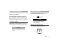
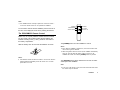
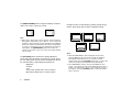
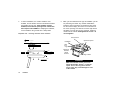
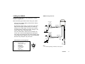
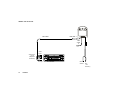
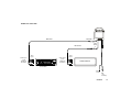
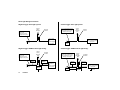
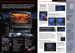
OHM 633
6.5" WIDESCREEN OVERHEAD COLOR LCD MONITOR
Owner's Manual / Installation Guide
6.5 INCH WIDE LCD MONITOR
OHM633
Warning!
Table of Contents
THE CLARION OHM633 OVERHEAD VIDEO MONITOR IS
DESIGNED TO BE VIEWED BY REAR-SEAT OCCUPANTS
ONLY!
1. Introduction .................................................................... 2
CLARION VIDEO PRODUCTS ARE NOT INTENDED FOR
VIEWING BY THE DRIVER WHILE THE VEHICLE IS IN MOTION.
SUCH USE MAY DISTRACT THE DRIVER OR INTERFERE WITH
THE DRIVER’S SAFE OPERATION OF THE VEHICLE, AND
THUS RESULT IN SERIOUS INJURY OR DEATH. SUCH USE
MAY ALSO VIOLATE STATE LAW.
3. Using the OHM633 .......................................................... 3
CLARION DISCLAIMS ANY LIABILITY FOR ANY BODILY
INJURY, INCLUDING FATALITIES, OR PROPERTY DAMAGE
THAT MAY RESULT FROM ANY IMPROPER OR UNINTENDED USES OF THIS PRODUCT.
7. Troubleshooting ........................................................... 15
About Installation
Installation of mobile audio and video components requires
experience with a variety of mechanical and electrical procedures. Even though this manual provides general installation
and operation instructions for your new Clarion OHM633
Overhead Video Monitor, it does not show the exact installation methods for your particular vehicle.
If you do not have the required knowledge and experience to
successfully complete the installation, we strongly recommend
consulting an authorized Clarion dealer about professional
installation options.
2. Care and Maintenance .................................................. 3
5. The Remote Control ....................................................... 5
6. Installation and Wiring ................................................... 7
8. Specifications ............................................................... 15
1.INTRODUCTION
What is included with the OHM633
●
The Clarion OHM633 is a high-performance video monitor
designed specifically for the mobile environment. It is
intended for use with other Clarion multimedia products, and
can also be integrated with many other products as part of a
complete mobile video solution. With two video inputs, the
OHM633 can support simultaneous connection to both
dedicated video source units and optional audio/video
components such as camcorders or videogames. The
infrared remote control receiver output allows integration with
select Clarion DVD and VHS source units.
The OHM633 automatically switches to operate with either
NTSC or PAL video signals (NTSC is the standard North
American video format).
The 16:9 aspect ratio screen allows DVD films to be viewed
in their original aspect ratio for the best cinematic experience.
Note:
The OHM633 is designed to be a component in a full audio/video
system. If you have any questions about compatible components,
such as system controllers, source units, FM modulators, or
other audio/video products, please contact your authorized
Clarion dealer.
2
OHM633
●
●
●
●
●
●
●
●
●
1 x OHM633 overhead monitor unit
1 x Soft trim ring
1 x Mounting bracket
1 x Remote control
2 x A/V wiring harness
1 x Power supply harness
2 x Battery AAA
4 x Screws M5 x 30
1 x Warranty card
1 x Owner’s Manual / Installation Guide
2. CARE AND MAINTENANCE
Liquids and the OHM633
4. USING THE OHM633
In order to operate the OHM633, the vehicle ignition key
switch must be in the ACC or RUN position.
Keep all liquids, including beverages and cleaning liquids,
away from the OHM633. Liquids inside the monitor can
damage the electronics, and result in electrical shock or fire.
If the unit should become wet, turn off all power and contact
an authorized Clarion dealer to have the monitor inspected.
Servicing the OHM633
In the event that trouble arises, never open the case or
disassemble the unit. The internal parts are not serviceable
by the user. Opening any components will void the warranty.
CAUTION!
Changes or modifications to this product not
approved by the manufacturer will void the
warranty.
ACC or engine
ON position
WARNING!
To prevent the battery from going dead,
operate this unit with the engine
running, if possible.
Deploying the fold-down monitor
1 Slide the release latch in the direction of the arrow on the
latch. The monitor will deploy about one inch.
Release
Latch
OHM633
3
2 Pull the monitor down into the viewing position. Grasp the
monitor by the edges - do not press on the screen.
Dome Light Switch Positions:
On ON, left position
Door-controlled - Center position
Off OFF, right position
Dome lights
Dome
Light
Sliding
Switch
Using the dome lights
The OHM633 has built-in dome lights which may replace the
original ceiling-mounted lights in some installations. These
lights illuminate when the doors are open and go out when
the doors are closed (some vehicles have domelight-delay
systems that keep the light illuminated for a few seconds
after the doors are closed). The OHM633’s lights may be
manually turned on and off with a sliding switch built into the
monitor.
WARNING!
To prevent the battery from going dead,
do not leave the dome light switch in the
ON position for long periods of time
without the engine running.
4
OHM633
Optional Infrared Wireless Headphones
The OHM633 has a built-in infrared audio transmitter to
accomodate optional wireless headphones.
Using the Remote Control
The OHM633 comes with a remote control, that is required
for basic operation of the monitor.The OHM633 also supports
the remote controls of selected optional Clarion multimedia
source units.This allows the user to control the source unit
with the source unit remote, even if the source unit is mounted
out of sight in a trunk or under a seat.
Note:
●
The OHM633 remote is always required to control the monitor source unit remote controls do not operate the OHM633.
POWER
WIDE/NORMAL
To use remote controls with the OHM633, point the remote at
the face of the deployed screen when pressing the buttons.
POWER
AV1/AV2
WIDE/NORMAL
PICTURE
SELECT
ADJUST DOWN
OHM633
SOURCE
PICTURE
ADJUST UP
The RCBOHM633 Remote Control
Before use, the 2 (AAA) batteries included must be inserted
into the remote control. Make certain that the batteries are
inserted according to the (+) and (-) marks on the inside of
the battery compartment.
Slide the battery door off and insert the batteries as shown.
+
-+
-
The [POWER] button turns the OHM633 on and off.
Notes:
-
●
+-
●
+
Even after the OHM633 is switched on, the screen remains dark
until a video signal is detected.
When the ignition switch is turned off, the OHM633 automatically
shuts off. The next time the ignition switch is turned on, the
OHM633 will remain off until the [POWER] button is pressed.
Notes:
●
The batteries should last about 6 months in normal use. Remove
leaking batteries immediately. Store the remote in a cool dark
place when not in use.
The [SOURCE] button selects between the two sets of audio/
video inputs of the OHM633.
Note:
●
If only one of the inputs is used, the screen will remain dark when
the unused input is selected.
OHM633
5
The [WIDE/ NORMAL] button changes the display mode from
“wide” 16:9 mode to “normal” 4:3 mode.
4:3
Change the value of each setting by pressing the [+] and [-]
buttons. Each setting has 42 steps of adjustment range.
16:9
Note:
●
BRIGHTNESS
When using a DVD player as the source unit, make sure that the
DVD player’s output mode is set to “Wide” or “16:9”, so that it will
generate a video signal that can take advantage of the OHM633’s
aspect ratio. When using this display with sources that generate
a “normal”, 4:3 image signal, such as videogames and videocassette players, the [WIDE/NORMAL] button will “stretch” the
image to fit the screen. In this case, some minor image distortion
may be visible.
CONTRAST
COLOR
TINT
MEM RESET
Notes:
The [PICTURE] button accesses the display adjustment
menus. Each time this button is pressed, the unit will step to
the next setting mode, and the screen will display the value of
the selected setting. These adjustment settings are:
Brightness
Contrast
Color
Tint (For PAL system.TINT control is dummy.)
Mem Reset (resets above to original values)
6
OHM633
●
●
When the “MEM RESET” option is displayed on the screen,
pressing either the [+] or [-] buttons will reset all settings to
their original factory values. If you do not wish to reset the
settings, either press the [PICTURE] button again, or wait for the
monitor to exit the picture adjustment mode automatically.
If the “MEM RESET” option is used and the OHM633 is set to
Source 2, the monitor will revert to the default setting of Source 1.
If there is no active input on Source 1, the screen may go dark. If
this happens, press the [SOURCE] button to switch the monitor
back to Source 2.
6. INSTALLATION AND WIRING
rough cloth, thinner , benzene, alcohol, or other solvent. The
screen surface is easy to scratch - do not rub when cleaning.
2. Installation Requirements
1. Before Starting
Read these instructions and the following precautions
carefully.
WARNING!
Be sure to disconnect the battery (-)
terminal before starting. This is to
prevent short circuits during installation.
WARNING!
Never install this monitor where it is
visible from the driver’s seat, or where it
could injure any vehicle occupant in
case of an accident. Ensure that your
installation does not create risk of headstrike injury, and that the monitor will
remain securely mounted in the case of
an accident or sudden maneuver.
Precautions
●
●
●
This unit is exclusively for cars with a negative ground, 12V
power supply.
Do not open the case. There are no user-serviceable parts
inside. If you require asistance, consult your Clarion dealer
or an authorized Clarion service center.
Use a soft, dry cloth to clean the screen. Never use a
OHM633
7
3. Installing the OHM633
light - for this reason, the OHM633 has dome lights built in which
can replace the original lights.
Prepare the vehicle for installation by carefully removing
vehicle interior trim panels as necessary. Route wire harnesses away from sharp edges, and ensure that no harnesses will be pinched or pierced during reassembly.
WARNING!
Never install any overhead monitor
such as to create a potential head strike
danger for the vehicle occupants. Avoid
mounting it too far forward in the vehicle
- always ensure that the front-seat
occupants cannot hit their heads on a
monitor when it is deployed.
Temporarily remove the OHM633 dome light lenses and
bulbs, so that the rear mounting screws can be accessed.
Note :
The wiring of the OHM633 must be completed, and the wiring
harness plugged in, prior to the final installation of the monitor
into the ceiling. However, since some vehicles will require
custom work or other modifications, this manual discusses
physical installation first. Always complete your wiring before
final assembly of the monitor into the ceiling of the vehicle.
The Installation Process
WARNING!
Make sure that the screws you use to
mount the bracket, monitor, or optional
spacer are not too long! If the screws
are too long, they could damage the roof
of the vehicle. Take great care when
planning this part of the installation.
Selecting the Monitor Location
Location of the overhead monitor varies by vehicle, but is
typically on the center line of the vehicle and just aft of the front
seats, often displacing the factory dome light. Always install
the overhead console to the existing roof cross beams.
Before you begin installation of the overhead console, remove
the vehicle dome light and partially drop the headliner to verify
that you have sufficient clearance and access to a roof beam.
Note:
In many vehicles, the OHM633 will displace the original dome
8
OHM633
1.
Remove the vehicle dome light and the trim on the
outer edges of the headliner. Determine the location
of the roof beam(s), which will help you determine
the monitor location. Ensure that the installation
can be successfuly completed before continuing!
2.
Determine if the mounting bracket can be attached to the
roof beam through the dome light opening in the headliner. This depends on the amount of space between the
headliner and the roof beam.
Exploded view - mounting through dome light opening
3.
A mounting spacer may be used to strengthen the
installation and to take up any gap between the headliner
and the roof beam. Screw the spacer to the roof beam,
and screw the bracket to the spacer.
Exploded view - mounting using a spacer:
Opening in headliner for dome light
Front of vehicle
Front of vehicle
Roof
Roof
Roof Beam
Roof Beam
Headliner
Mounting
Bracket
Optional Spacer Material
(Installer Provided)
Headliner
Opening in headliner for dome light
Screws
Screws
Overhead Monitor
Screws
Mounting
Bracket
Screws
Overhead Monitor
Screws
Note :
● If there is too much space between the roof beam and the
headliner, the headliner could crush and wrinkle when the
monitor and bracket are assembled. Verify all clearances to
prevent damage to the vehicle or the interior trim!
OHM633
9
4.
In some installations, the vehicle headliner must
modified, and the bracket must be sandwiched between
the headliner and the roof. If the headliner must be
modified, ensure that the opening will be smaller than
the footprint of the OHM633. If modifying the headliner,
cut the headliner using a knife with a sharp blade.
Exploded view - mounting w/bracket above headliner:
5. When you have determined the type of installation you will
be performing and made any needed modifications,
install the wiring harnesses as needed and plug them
into the monitor. Deploy the monitor to access the front
two screw openings, and remove the dome light lenses
and bulbs to access the rear two openings. Install the
monitor into the vehicle. Hand-tighten the screws - do
not overtighten!
Vehicle Roof
Front of vehicle
Roof Beam
Soft
trim
ring
Optional Spacer Material
(Installer Provided)
Screws
Bracket
Enlarged
opening
in headliner
Optional spacer
Headliner
Roof
Headliner
Screws
Overhead Monitor
Mounting
bracket
above
monitor
Mounting screws
Screws
WARNING!
Make sure that the screws you use to
mount the bracket, monitor, or optional
spacer are not too long! If the screws
are too long, they could damage the roof
of the vehicle.
10
OHM633
5. Wiring the OHM633
OHM633 wiring harnesses:
The following pages display wiring diagrams for various
OHM633 configurations.
Read the following precautions before wiring your system.
Audio input 1
(for IR
headphone
transmitter)
Disconnect the negative battery terminal before making
any wiring connections.
Be particularly careful where you route wires. Keep them
away from the engine, exhaust system, etc. Heat may
damage wires. Sharp edges can pierce wire insulation
and cable jackets, causing short circuits, damage to the
vehicle, blown fuses, and system failure.
IR output
Data
If the fuse should blow, make sure all connections are
correct and no wires are damaged before replacing the
fuse. Always use fuses that are the same amperage value
as the original. When replacing a fuse, never let the battery
side touch any metal part or any other wire.
Audio input 2
(for IR
headphone
transmitter)
DIN cable 2
input 2
IR output
DIN Connector pin assignments
Pin
Description
1
2
3
4
5
6
7
8
DC 12V (+) ACC
Infrared receiver signal
DC Ground (-)
Video signal in
A/V signal ground
Audio R signal in
Not used
Audio L signal in
DIN cable 1
Video
input 1
Blac k Ground
Data
2
3
1
4
6
8
7
Red
+12V
Accessory
Note :
For dome light wiring connections, see page 14.
5
OHM633
11
OHM633 with VS738 DVD
DIN cable 1
DIN cable 1
DIN
cab le
2
Audio input 1
(for IR
headphone
transmitter)
Video
input 1
OP E N
OHM633
R E P E AT
T IT L E
A
C HP
B
TR K
R E MA IN
A NG L E
DOL B Y
DIG ITA L
VC D
CD
MP 3
IR output
12
SCN
R DM
DV D
P OW E R
L / R
VS 738 DVD
Blac k Ground
Red
+12V
Accessor y
OHM633 with VS738 DVD
DIN cable 1
DIN cable 1
DIN cable 2
Audio input 1
(for IR
headphone
transmitter)
Video
input 1
OP E N
SCN
R DM
DV D
P OWE R
A
C HP
B
TR K
CD
MP 3
IR output
R E P E AT
T IT L E
VCD
L / R
VS 738 DVD
R E MA IN
A NG L E
DOL B Y
DIG ITA L
Audio input 2
(for IR
headphone
transmitter)
DIN
cable
2
Video
input 2
GAME CONSOLE
IR output
Blac k Ground
Red
+12V
Accessor y
OHM633
13
Dome Light Wiring Connections:
Negative-trigger dome light system:
Positive-trigger dome light system:
Original
Factory
Domelight
Bulb
(-) Output from door jamb
pin switch, OR
(-) output from vehicle
domelight control system
12V (+) switched output when door
is open (output is either from the
door pin switch OR the vehicle
domelight control system).
Domelight
connector
12V (+) to Bulb
from fuse box
OR
vehicle domelight
control system
(-) Ground
Negative-trigger OHM 633 dome light wiring:
Original
Factory
Domelight
Bulb
(-) Output from door jamb
pin switch, OR
(-) output from vehicle
domelight control system
White wire,
OHM 633
(-) Ground
Gray wire,
OHM 633
(-) Ground
14
OHM633
Domelight
connector
(-) Constant ground, OR
output from vehicle domelight
control system
12V (+)
Constant
(-) Ground
Positive-trigger OHM 633 dome light wiring:
Domelight
connector
Brown wire,
OHM 633
Original
Factory
Domelight
Bulb
12V (+) switched output when door
is open (output is either from the
door pin switch OR the vehicle
domelight control system).
Original
Factory
Domelight
Bulb
White wire,
OHM 633
12V (+) to Bulb
from fuse box
OR
vehicle domelight
control system
12V (+)
Constant
Domelight
connector
Brown wire,
OHM 633
(-) Constant ground, OR
output from vehicle domelight
control system
Gray wire,
OHM 633
(-) Ground
6. TROUBLESHOOTING
7. SPECIFICATIONS
No picture.
Supply voltage: 12V DC (10V-16V)
Press the [POWER] and [SOURCE] buttons to make sure the
monitor is on and the proper input is selected.
Test voltage: 12V, negative ground
If there is still no picture, press the [PICTURE ] button. If the
menu appears, check the source unit and video connections.
If no menu appears, check all fuses and power connections
to the OHM633 and the associated equipment.
Operating T emperature: -10o C to 60o C (14o F to 140o F)
Note:
●
The OHM633 has an operating temperature range of
-10o C to 60o C (14o F to 140o F). If the temperature is outside
this operating range, the unit will not turn on, or the screen
may be slow to react to image changes. The monitor will
function normally once it returns to its proper operating
temperature range.
With a DVD player and a widescreen DVD disc, there are
black bars on the screen.
Current consumption: Less than 1.0 Amps
Signal system: NTSC and PAL composite video 1.0V p-p
Screen: 6.5” diagonal, 144.4mm x 80.3 mm.
Resolution: 1200 x 234 (280,800 dots)
Weight: 2.2 lb, 1.0 kg
Note:
● The technical data and the design of the equipment may change
for the sake of technical improvements without prior notice.
Clarion Co., Ltd.
Made in Taiwan
Change the TV display mode to “Wide” in the DVD player’s
Setup menu.
After changing this setting, if there are still black bars, press
the [WIDE/NORMAL] button on the OHM633 remote control.
OHM633
15
OHM 633
6.5" WIDESCREEN OVERHEAD COLOR LCD MONITOR
Owner's Manual / Installation Guide
www.clarion.com
6.5 INCH WIDE LCD MONITOR
2003 Clarion Corporation
All rights reserved. This material may not be reproduced or copied, in
whole or in part, without the written permission of Clarion Corporation.