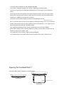
1
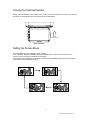
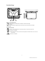
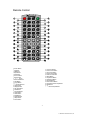
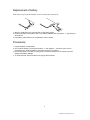
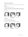
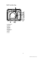
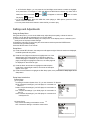
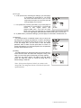
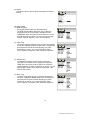
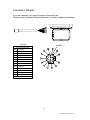
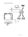
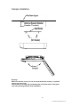
OWNER’S GUIDE
INSTALLATION GUIDE
15.4” (16:9)
Overhead Video
Monitor
MODEL OHD1502
© 2004 Directed Electronics, Inc. N82104 05-04
.
Welcome!
Thank you for your purchase of Directed’s Overhead Monitor with integrated DVD. Prior to
operating this unit, please fully read this instruction manual and retain it for future reference.
Warning!
The overhead monitor system is designed strictly for rear-seat entertainment.
Viewing the monitor while operating a motor vehicle can result in serious injury
and/or property damage. Directed is not responsible for any injury and/or
property damage as a result of the improper use or viewing of the monitor.
© 2004 Directed Electronics, Inc
NON-TRANSFERABLE LIMITED CONSUMER WARRANTY
Directed Electronics, Inc. (Directed) promises to the original purchaser that the automotive video monitor and/or source
unit(s) (the Product), excluding accessories, purchased and installed from a Directed authorized dealer within the ninety
(90) days after purchase of the new vehicle, in which the Product is installed, is free from defects in materials or
workmanship under normal use and conditions for a period of three (3) years from date of purchase or the first 36,000
miles as registered on the new vehicle's odometer reading at time of delivery of the Product for warranty service,
whichever occurs first. Product purchased or installed more than ninety (90) days after the new vehicle is purchased are
warranted for a period of one (1) year from date of purchase of the Product.
Directed promises to the original purchaser that all video accessories will be free from defects in materials and
workmanship under normal use and condition for a period of ninety (90) days after the date of purchase. A sales receipt
and/or warranty registration card is required to provide proof of date of purchase of the Product or accessories.
Should the Product be determined defective during the applicable warranty period, the Product will be repaired or
replaced with a new or comparable reconditioned part(s), at Directed's option. To obtain warranty service, the Product
must be returned to a Directed authorized dealer along with proof of purchase and installation.
Note: This warranty does not cover labor costs for the removal and reinstallation of the Product. IN ORDER FOR THIS
WARRANTY TO BE VALID, YOUR PRODUCT MUST BE SHIPPED WITH PROOF OF PURCHASE AND
INSTALLATION BY AN AUTHORIZED DIRECTED DEALER. ALL PRODUCTS RECEIVED BY DIRECTED FOR
WARRANTY REPAIR WITHOUT PROOF OF DIRECTED DEALER INSTALLATION WILL BE DENIED.
This warranty is non-transferable and does not apply to any Product that has been modified or used in a manner contrary
to its intended purpose, and does not cover damage to the Product caused by installation or removal of the Product. This
warranty is VOID if the product has been damaged by accident or unreasonable use, negligence, acts of God, neglect,
improper service or other causes not arising out of defect in materials or construction. This warranty does not cover the
elimination of externally generated static or noise, or the correction of antenna problems or weak television reception,
damage to tapes, video games, software, camcorders, discs, speakers, accessories or vehicle electrical systems,
cosmetic damage or damage due to negligence, misuse, abuse, failure to follow operating instructions, accidental spills or
customer applied cleaners, damage due to environmental causes such as floods, airborne fallout, chemicals, salt, hail,
windstorms, lightning or extreme temperatures, damage due to accidents, road hazards, fire, theft, loss or vandalism,
damage due to improper connection to equipment of another manufacturer, modification of existing equipment, use of a
faulty tape cartridge or cleaning of the VCR head, or Product which has been opened or tampered with for any reason or
which has been damaged due to alteration or service performed by anyone other than Directed Electronics, Inc.
ALL WARRANTIES INCLUDING BUT NOT LIMITED TO EXPRESS WARRANTY, IMPLIED WARRANTY, WARRANTY
OF MERCHANTABILITY, FITNESS FOR PARTICULAR PURPOSE, AND WARRANTY OF NON-INFRINGEMENT OF
INTELLECTUAL PROPERTY ARE EXPRESSLY EXCLUDED TO THE MAXIMUM EXTENT ALLOWED BY LAW, AND
DIRECTED NEITHER ASSUMES NOR AUTHORIZES ANY PERSON TO ASSUME FOR IT ANY LIABILITY IN
CONNECTION WITH THE SALE OF THE PRODUCT. DIRECTED HAS ABSOLUTELY NO LIABILITY FOR ANY AND
ALL ACTS OF THIRD PARTIES INCLUDING ITS LICENSED DEALERS OR INSTALLERS. IN NO EVENT WILL
DIRECTED ELECTRONICS, INC. BE LIABLE FOR ANY INCIDENTAL, SPECIAL OR CONSEQUENTIAL DAMAGES
(INCLUDING LOSS OF PROFITS), BY PURCHASING THIS PRODUCT, THE CONSUMER AGREES AND CONSENTS
THAT ALL DISPUTES BETWEEN THE CONSUMER AND DIRECTED SHALL BE RESOLVED IN ACCORDANCE
WITH CALIFORNIA LAWS IN SAN DIEGO COUNTY, CALIFORNIA.
Some states do not allow limitation on how long an implied warranty lasts. In such states, the limitations or exclusions of
this Limited Warranty may not apply. Some states do not allow the exclusion or limitation of incidental or consequential
damages. In such states, the exclusion or limitation of this Limited Warranty may not apply to you. This Limited Warranty
gives you specific legal rights, and you may have other rights which vary from state to state.
Some states do not allow the exclusion or limitation of incidental or consequential damages. In such states, the exclusion
or limitations of this Limited Warranty may not apply to you. This Limited Warranty gives you specific legal rights and you
may have other rights which vary from state to state.
© 2004 Directed Electronics, Inc
Important Information
FCC NOTICE
This device complies with Part 15 of FCC rules. Operation is subject to the following two conditions:
(1) This device may not cause harmful interference, and (2) this device must accept any interference
received, including interference that may cause undesirable operation.
Changes or modifications not expressly approved by the party responsible for compliance could void
the user's authority to operate this device.
YOUR WARRANTY
Your warranty registration must be completely filled out and returned within 10 days of purchase. Your
product warranty will not be validated if your warranty registration is not returned. Make sure you
receive the warranty registration from your dealer. It is also necessary to keep your proof of purchase,
which reflects that the product was installed by an authorized dealer.
© 2004 Directed Electronics, Inc
TABLE OF CONTENTS
Safety Instructions and Cautions . . . . . . . . . . . . . . . . . . . . . . . . . . . . . . . . . . . . . . . . . . . . . . . . . 1
Important . . . . . . . . . . . . . . . . . . . . . . . . . . . . . . . . . . . . . . . . . . . . . . . . . . . . . . . . . . . . . . . . . . . . . 2
Installation Guide . . . . . . . . . . . . . . . . . . . . . . . . . . . . . . . . . . . . . . . . . . . . . . . . . . . . . . . . . . . . . 3
Operating Monitor . . . . . . . . . . . . . . . . . . . . . . . . . . . . .. .. . . . . . . . . . . . . . .. . . . . . . . . . . . . . . .. . 4
Open/Close the Display Monitor ........................................................................................... 4-5
Function Keys . . . . . . . . . . . . . . . . . . . . . . . . . . . .. . . . . . . . . . . . . . . . . . . . . . . . . . . . . . . . . . . . 6
Remote Control Unit . . . . . . . . . . . . . . . . . . . . . . . . . . . .. . . . . . . . . . . . . . . . . . . . . . . . . . . . . 7
Replacement of Battery ............................................................................................................... 8
Loading and Unloading Discs . . . . . . .. . . . . .. . . . . . . . . . . . . . .. .. . . . . . . . . . . . . . . . . . .. . . . . 9
Basic Functions . . . . . . . . . . . . . . . . . . . . . . . . . . . . . . . . . . . . . . .. . . . . . . . . . . . . . . . . . . . . . . 10
DVD Playback ........................................................................................................................ 10
MP3 Playback ......................................................................................................................... 10
Settings and Adjustments . . . . . . . . . . . . . . . . . . . . . ... . . . . . . . .. .. . . . . . . . . . . . . . . . . . . . . . 12
Installation . . . . . . . . . . . . . . . . . . . . . .. . . . . . . . . .. . . . . . . . . . . . . .. . . . . . . . . . . . . . . . . . . . 16
Package Contents . . . . . . . . . . . . . . . . . . . . . .. . . . . . . . . . . . . . . . . . . .. . . . . . . . . . . . . . . . . . 21
Troubleshooting . . . . . . . . . . . . . . . . . . . . . .. . . . . . . . . . . . . . . . . . . . . . .. . . . . . . . . . . . . . . . . 22
Specifications . . . . . . . . . . . . . . . . . . . . . .. . . . . . . . . . . . . . . . . . . . . . .. . . . . . . . . . . . . . . . . . 23
© 2004 Directed Electronics, Inc
Safety Instructions and Cautions
WARNING : TO REDUCE THE RISK OF FIRE OR ELECTRIC SHOCK, DO NOT
EXPOSE THIS EQUIPMENT TO RAIN OR MOISTURE. TO REDUCE THE RISK
OF FIRE OR ELECTRIC SHOCK AND ANNOYING INTERFERENCE, USE ONLY
THE INCLUDED HARDWARE.
THIS MONITOR IS ONLY DESIGNED FOR REAR SEAT PASSENGER VIEWING
AND IS NOT INTENDED FOR VIEWING BY THE DRIVER WHILE THE VEHICLE IS
IN MOTION. SUCH USE MAY DISTRACT THE DRIVER OR INTERFERE WITH THE
SAFE OPERATION OF THE VEHICLE, AND MAY ALSO VIOLATE STATE LAW.
DIRECTED ELECTRONICS, INC. DISCLAIMS ANY LIABILITY FOR ANY BODILY
INJURY, INCLUDING FATALITIES, OR PROPERTY DAMAGE THAT MAY RESULT
FROM ANY IMPROPER OR UNINTENDED USES OF THIS PRODUCT.
SHOULD THE LCD PANEL BREAK OR LEAK FLUID, AVOID ALL CONTACT WITH
THE UNIT. IF YOU SHOULD COME IN CONTACT WITH THE LEAKED FLUID,
WASH THE AFFECT AREA THOROUGHLY WITH WAS AND SEEK IMMEDIATE
MEDICAL ATTENTION.
■ During operation, if the unit should over-heat or malfunction, switch off the unit and see your
dealer. Do not disassemble the unit as there are no user-serviceable parts in this unit and the
warranty will be voided.
■ Should there be a need to replace a blown fuse, turn off the unit and disconnect all power to
the player. Use only the correct rating fuse to avoid electrical damage to the unit.
■ Only operate the monitor as described in this guide. Attempts to use or modify this monitor
contrary to the descriptions in this guide may cause damage and void the warranty.
■ Extremes in temperature can cause abnormal display operation. This monitor has an optimal
operating temperature range between 35-115 degrees Fahrenheit. If the vehicle interior is
outside this range, do NOT operate the monitor until the temperature is within its operating
range.
■ Exposure to moisture or dust can cause harmful damage to the internal electronics. Do not
mount near cup holders or in areas where spills may occur.
■ This monitor is designed for use in vehicles with standard (-) 12 volt ground electrical systems.
■ Do not operate for an extended period of time without the engine running or the vehicle’s battery voltage may drop to damaging levels.
■ Do not drop the LCD panel or subject it to direct impact. This will damage the panel and/or the
back light element.
■ When operating the unit, avoid contact with the LCD panel.
■ Prevent metal or foreign objects being locked between the LCD screen and the enclosure.
Foreign objects may impair smooth running of the disc and may cause electrical problems.
■ Keep unit away from equipment with strong magnets such as large loudspeakers.
■ To prevent malfunction, do not play discs other than the ones listed below: DVD audio discs,
DVD-ROMs, CD-ROMs, Photo CDs and DVDs with region numbers other than this player's
region number.
1
© 2004 Directed Electronics, Inc
Important
WHEN CLEANING THE VEHICLE
Do not spray this unit with water or cleaning solutions. Moisture and the chemicals found in cleaning fluids could damage the consoles finish and interior electronics. A soft damp, lens cleaning
cloth should be used to wipe the screen.
WHEN DRIVING
This unit is intended for use in the rear seat area only. It should not be installed in a location that
would allow the driver to view it while driving.
WHEN PARKED
The screen is easily removable. Always close the screen when parking for an extended period of
time to avoid potential theft or extended exposure to direct sunlight.
PROPER USE
Do not touch the screen. Do not pull or hang from the fold down monitor door.
REPAIRS
If the monitor stops working for any reason, discontinue use immediately and consult with your
retailer about any necessary repairs.
RADIO/TV TUNER USE
When the unit is used in conjunction with a Radio/TV tuner, please assure that the receiver is manufactured to receive television broadcast signals that are transmitted via terrestrial radio waves.
Reception quality will change and vary according to vehicle location and weather conditions.
INSTALLATION
Avoid installing the monitor at a location, where it will be under direct sunlight or a hot air vent.
Operating temperature of the unit is from 32-140 degrees Fahrenheit. Install the unit at a dry location, where it is away from condensation. Only correct size of fasteners or installation cables
should be used during installation. Failure to do so may cause a mechanical failure and create a
fire hazard. The installation should be done by an authorized Directed dealer.
NOTE: If the internal temperature of the vehicle is higher than the normal operating temperature,
please allow the vehicle to cool down prior to operating the unit.
PICTURE QUALITY
The picture quality of this LCD unit depends strictly on its installed location. To achieve the best picture
quality, adjust the brightness control or viewing angle of the unit until the optimum viewing is achieved.
Installation Guide
2
PRECAUTIONS
© 2004 Directed Electronics, Inc
This unit should be installed by an authorized Directed dealer.
This product is designed to operate with a 12V DC, negative ground battery system.
Disconnect the ground wire from the battery terminal prior to connecting the unit to the electrical
system.
The wiring from some other products or accessories might bear similar color code as this product;
however, they might be of other function. Please refer to the electrical connection diagrams of this
product prior to installing to avoid improper connection.
Use proper connectors and insulation to prevent electrical damage to the unit.
© 2004 Directed Electronics, Inc.
Do not connect the yellow wire and red wire together of this product directly to the +12V. Connect the
red wire of this product to the ACC of the ignition key switch and yellow wire to +12V. Failure to do so
may result in permanent drainage of the battery charge.
Only supplied accessories should be used to avoid damage to the unit during installation.
Ensure that the display monitor is suitably installed at a location, such that it will not obstruct the rear
view mirror and/or the air condition vents.
Do not install this unit at a declining angle exceeding 30 degrees.
Do not install screws over the plane surface, which may affect monitor eject or retract function.
Opening the Overhead Monitor3
Press the “OPEN” button to release the overhead monitor.
closed position
© 2004 Directed Electronics, Inc
open position
NOTE: The vehicle’s ignition key must be “ON” or “ACC” position for the monitor to have power.
OFF
ACC
ON
4
© 2004 Directed Electronics, Inc
Closing the Overhead Monitor
Gently push the backside of the monitor until it clicks into the overhead monitor housing. The monitor
will switch off automatically when it is returned to the closed position.
to the
closed position
open position
Setting the Screen Mode
The overhead monitor has 4 different screen modes:
FULL, NORMAL, WIDE and ZOOM. Pressing the MODE button on the front control panel or the
remote control can access the different screen modes.
The current mode is displayed on the screen first. Each time the MODE button is pressed, the screen
mode switches in the following sequence:
5
© 2004 Directed Electronics, Inc
Function Keys
5
9
6
7
8
9
4
1
2
3
DISPLAY FUNCTION KEYS
1.
Courtesy Light Button: Activate this switch to “ON/OFF” to activate the dome lights.
2. Open/Close Button
Door Light On/Off Button: Engage this switch to have the door open switch activate the dome lights.
3.
4. IR Transmitter
UNIT FUNCTION KEY
5.
Power Button: Switch Audio/Video source. Press Power button over 4 seconds can switch on/off.
6.
Selects the items to be adjusted.
7.
Menu Button: Press the menu button to access the monitor adjustments. Press Menu button over 1 second can
turn FM on/off.
8.
Selects the items to be adjusted.
9. IR Sensor
6
© 2004 Directed Electronics, Inc
Remote Control
PO WER
IR
FM
PIP
SO URC E
MENU
M ENU PBC
TITLE
IM AG E
C LEAR
DISPLAY
SUBTITLE
SLO W
PRO G RAM
ANG LE
AUDIO
MUTE
REPEAT
SETUP
ZO O M
ENTER
MO D E
1 Power Button
○
○2 IR Button
○3 FM Button
○4 Eject Button
○5 PIP Button
○6 Source Button
○7 Menu Button
○8 . 1○2 Λ
Button
○9 Menu PBC Button
1○0 Title Button
1○1 Image Button
1○3-○
23 Numeric Buttons
2○4 Clear Button
2○5 Display Button
2○6 Sub Title Button
2○7 Slow Button
2○8 Program Button
2○9 Angle Button
3○0 Audio Button
3○1 Mute Button
3○2 Repeat Button
3○3 Setup Button
3○4 Zoom Button
3○5
Up Cursor Button
Down Cursor Button
3○7 Left Cursor Button
3○8 Right Cursor Button
3○9 Enter Cursor Button
4○0 Mode Button
4○1 Play/Pause Button
4○2 Headphone Button
4○3 Reverse Button
4○4 Fast Forward Button
4○5 Previous/Preserve Skip Button
4○6 Next Button
4○7. 4○8 Volume Adjust Button
3○6
7
© 2004 Directed Electronics, Inc
Replacement of battery
NOTE : Before using remote after installation, remove the battery plastic protective slip.
2
1
1. Move the small latch to the right and slide out the battery holder.
2. Remove old battery and replace it with a new battery (CR2025) with the positive “+” sign facing as
shown above.
3. Push battery holder back into its compartment until it is locked.
Precautions
1. Properly dispose of used battery.
2. Do not misuse battery by shorting the positive “+” and negative “-” terminal or put it into fire.
Overheating may cause the battery to explode and cause a fire hazard.
3. If the remote is not to be used for a long period, remove the battery from the remote to prevent
damage from battery leakage.
4. To avoid accidents, prevent children from playing with the battery.
8
© 2004 Directed Electronics, Inc
Loading and Unloading Disc
You can use single side and dual layer DVDs, VCDs, CD-audio and CD-R compatible 12cm discs with
this system.
Loading Discs
1. Press at the upper right corner to open the door.
2. Load with the recorded side (the shiny side) facing up. With double-sided discs, load with the side
you want to watch facing up. Ensure that the disc is seated properly before pushing tray back into its
locking position.
3. Push to close the door.
Unloading Discs
1. Press at the upper right corner to open the door.
2. Remove the disc. (Avoid touching the recorded surface.)
3. Push to close the door, until you hear a click sound from the door mechanism.
© 2004 Directed Electronics, Inc
DVD Function Key
2
3
4
5
8
9
6
1
1
○
○3
○4
○5
○6
○7
○8
○9
1○0
1○1
1○2
1○3
1○4
7
Lock/Unlock Button
Audio Button
Menu Button
Up Button
Down Button
Left Button
Right Button
Enter Button
Play/Pause Button
Stop Button
MS Card
SD Card
CF Card
10
© 2004 Directed Electronics, Inc
DVD Playback
Press the Power button on the player or the remote controller, and “Read” appears on the
TV screen. If there hasn’t a disc in the DVD player, “No disc” will be displayed on the screen.
Load a disc into the unit.
The contents of each disc menu vary according to how the disc was authored and what features are
included. The disc menu will be turned on for you to select, when Menu button pressed. Also play and
pause can be switched with the Pause button on the remote. When a DVD disc is loaded, you can
press Arrow buttons to highlight the menu item you want to choose. Press Enter or Play button, you
can begin play with the highlighted.
Stopping Playback
When you press Stop button for the first time, the player turns into quasi stop state. At the same time
the OSD appears “Pre Stop”. To begin the title over, press Stop twice.
In quasi stop state, the player remembers where you stopped, when you start playing the disc again,
the DVD player picked up where you left off.
In stop state, when you press Play, the player enters sequence playback mode.
Selecting a Track or Chapter
Selecting tracks or chapters can be accomplished by either using the IR remote or front mounted
controls. These controls allow the operator to skip over undesired tracks or repeat a particular track.
When playing a DVD disc, press Numeric buttons on the menu or title page to select tracks; During
DVD playback, you can input desired title number directly.
MP3 Playback On CD
Place a MP3 / JPEG disc into the tray, and the player will auto search the directories saved MP3 /
JPEG files. After searching, it will auto go to the first directory saved MP3 files (to the disc containing
both mp3 and jpeg files; to the disc containing single type of files, it will auto go to the first directory)
and play the first song in the directory.
1. Press the Left and Right arrow buttons, you can activate Directory Region, File Region and File
Switch Region separately.
2. The highlight in Directory Region and File Region is shown as the picture above; while it appears
a transparent rectangle in File Switch Region.
11
© 2004 Directed Electronics, Inc
3. In File Switch Region, you can press the Left and Right arrow buttons to switch the highlight,
then press Enter. For example, if a disc with MP3 and JPEG files but without any Video files is
loaded, the color of the letter “
” and “
” will appear to white and “
” black. If a MP3
” turns red.
file playing, “
4. To the disc with WMA, MP3 and JPEG files, when playing a JPEG picture, press the STOP
button to return to JPEG list.
5. You can press the Numeric buttons to select the file you want to play.
Settings and Adjustments
Using the Setup Menu
Using the setup menu, you can do the initial setup, adjust the picture quality, and set the various
outputs. You can also set a language for the on-screen display.
(1) Press remote SETUP button to display the “setup menu” on the display screen. It will allow you to
modify some of the player’s basic settings.
(2) Select the main item you want using the cursor buttons and then press the ENTER button.
To Cancel Using the Setup Display
Press the SETUP button on the remote.
Setup Menu
(A) Press remote SETUP button, the setup menu will appear as right. When the main menu displayed,
the DVD system will auto pause.
(B) Press the Left / Right arrow buttons to highlight the icon of the
desired page, then press the Down or Right arrow button to
activate that page; For example, if you want to setup the video
page, press Right to highlight the video icon, the video page will
be displayed on the screen as right.
(C) Press the Down arrow button to highlight the desired option.
Press Enter or press Right to select, the choices of that option
appear on the right.
(D) Press the Arrow buttons to highlight the Exit Setup option, then press Enter or Setup again to exit
Setup Menu.
Setup Items Introduction
System Setup
(1) TV System
According to the Color System of the TV, you can choose the TV System.
NTSC: Choose this settings if your DVD player is connected to a
NTSC TV.
PAL60: Choose this settings if your DVD player is connected to a
PAL60 TV.
PAL: Choose this settings if your DVD player is connected to a
PAL TV.
AUTO: Choose this settings if your DVD player is connected to a
multi-system TV.
12
(2) Screen Saver
ON: Choose this setting to activate the screen saver.
OFF: Choose this setting to cancel the screen saver.
© 2004 Directed Electronics, Inc
(3) TV Type
4 : 3 PS (Pan & Scan): Choosing this setting if your DVD player
is connected to a normal ratio TV. You can fill
the movie to the entire screen of your TV. This
might mean that parts of the picture (the left
and right edges) won’t be seen.
4 : 3 LB (Letter Box): Choosing this setting if your DVD player is
connected to a normal ratio TV. You’ll see the
movies in their original aspect ratio
(height-to-width ratio). You’ll see the entire
frame of the movie, but it will take up a smaller portion of the screen vertically.
The movie might appear with black bars at the top and bottom of the screen.
16 : 9 (Wide Screen): Choose this setting if your DVD player is connected to a wide screen TV.
(4) Password
The password option is initialized locked, and you cannot set
the ratings limit or change the password. In order for the Ratings
feature work, the password mode must be turned on. If you want
to set the ratings limit, you will need to enter the default
password, which is 0000, and then press Enter to confirm. To
change the password, you will be prompted for the old password,
and then be prompted for a new.
(5) Rating
The Rating feature is a rating limit system, like movie ratings. It
works with DVD discs that have been assigned a rating. This
helps you control the types of DVDs that your family watches.
There are two rating options: NO ADULT and KID SAFE.
Select the VIEW ALL option to cancel the rating limit. The
default setting is VIEW ALL.
Notes: If the password option is locked, you cannot set the
ratings limit; the rating limit doe not work when the password
option unlocked.
13
© 2004 Directed Electronics, Inc
(6) Default
Choose this option to resume all the setup options to default
settings.
SCREEN SAVER
Language Setup
(1) OSD Language
The language setup options are illustrated below:
The OSD Language Menu allows the user to select the
language for the on-screen display. Highlight the OSD
LANGUAGE option, and press the Arrow buttons to choose
the OSD language you prefer. The user can select English,
Chinese, German, Spanish, French, and Portuguese.
(2) Audio Lang
The Audio Lang Menu allows the user to select the language
for the disc. Highlight the AUDIO LANG option, and press the
Arrow buttons to choose the audio language you prefer.
Press Enter to confirm. You can select English, Japan,
French, Spanish, Portuguese, Latin, German and Chinese.
(3) Subtitle Lang
The Subtitle Lang Menu allows the user to select the
language for the subtitle of disc. Highlight the SUBTITLE
LANG option, and press the Arrow buttons to choose the
subtitle language you prefer. Press Enter to confirm. You can
select English, Japan, French, Spanish, Portuguese, Latin,
German and Chinese.
(4) Menu Lang
The Menu Lang allows the user to select the language for
the menu. Highlight the MENU LANG option, and press the
Arrow buttons to choose the menu language you prefer.
Press Enter to confirm. You can select English, Japan,
French, Spanish, Portuguese, Latin, German and Chinese.
14
© 2004 Directed Electronics, Inc
Installation
About the Installation
The installation of the overhead monitor system requires experience in both mechanical and
electrical procedures. If you do not posses the necessary experience or tools to attempt this
installation, contact a local Clarion dealer for assistance. Improper installation can result
damage to the monitor and/or the vehicle.
This manual provides basic installation tips and techniques to aid in the installation of the
overhead monitor system. The installation instructions are not vehicle specific, it’s a
guideline on how to perform the installation.
Prior to Beginning Installation
•Verify that all of the functions of the vehicle work properly (i.e.: power windows, power door
locks, air conditioning, lights, etc.)
•Verify the monitor will not interfere with the operation of the sunroof, if applicable.
•Test fit the location of the overhead monitor system to ensure it will not interfere with the
safe operation of the vehicle.
•Determine the location of the AV source(s).
•This unit is exclusively for vehicles with a negative ground, 12V power supply.
•Do not open the case; there are no serviceable parts inside. If you drop anything into the
unit during installation, consult with your dealer or an authorized Clarion service center.
WARNING!
Be sure to disconnect the battery (-) negative terminal before starting.
This is to prevent short circuits during the installation.
15
16
© 2004 Directed Electronics, Inc
Installation Procedure
1. Identify the polarity of the dome light circuit and set the switch on the bottom of the
overhead monitor housing.
2. Test fit the overhead monitor system on the ceiling of the vehicle, verifying it is not going
to interfere with the safe operation of the vehicle.
3. Once the mounting location of the overhead monitor system has been determined,
carefully mark the location with masking tape.
4. Lower the vehicle’s headliner down to see if a roof support beam is available to screw the
mounting bracket to. If a support beam is not available to screw into, use a ¾” piece of
plywood cut to the appropriate size. Attach the plywood to the roof of the vehicle using
silicone allowing adequate drying time.
5. Screw the mounting bracket in the vehicle. DOUBLE CHECK THE LENGTH OF THE
SCREWS PRIOR TO MOUNTING THE BRACKET.
6. Cut a 1” hole in the headliner along the backside of the mounting bracket for the cables to
pass through.
7. Route cables through the hole to the predetermined location of the AV source(s).
8. Identify the dome light wires in the vehicle and connect them to the corresponding dome
light wires on the overhead monitor system.
9. Plug in the AV cables and power harness into the overhead monitor system.
10. Carefully hold the overhead monitor system to the mounting bracket aligning the
mounting holes while screwing in the screws. (Make sure the wires and cables are not in the
way while mounting the monitor).
11. Connect the Red wire of the power harness to the Accessory wire in the ignition
harness.
12. Ground the Black wire of the power harness to a clean ground spot.
Note: Make sure you keep the ground wire of the model and video source as short as
possible to prevent any type of unwanted vehicle noise.
17
© 2004 Directed Electronics, Inc
Connection Diagram
If you are uncertain as to what the proper connections are.
Please contact a qualified Directed technician for further installation assistance.
A/V Cable
A/V Input Connector
Pin Function
1
Audio B-L
2
IR EXT
3
Audio B-R
Audio A-L
4
ACC
5
Audio A-R
6
MUTE
7
8
Video 2
9
GND
10
Source select B
11
12V
12
Source select A
GND A/V GND Shielding
GROUND
9
5
7
2
3
1
6
8
4
18
© 2004 Directed Electronics, Inc
Complete System Diagram
VCR
YELLOW (+12V)
Video Out
BLACK (GEN
)
Power
OUT
RED (ACC)
IN
DVD
YELLOW (B+)
BLACK (GEN
IN
DVD
)
GRAY (Door Switch)
IR Transmitter
© 2004 Directed Electronics, Inc
19
Sample Installation
Warning!
Make sure that the screws you use to mount the bracket, monitor, or optional
spacers are not to long!
If the screws are to long, they will damage the roof of the vehicle. Take great
care when planning this part of the installation.
20
© 2004 Directed Electronics, Inc
Package Contents
1
Overhead Monitor
1 5M Power Cable
1 75cm Power Cable
1 Metal Mounting Bracket
1 Screws For Metal Mounting Bracket
1 IO Box
1 Trim Ring
1 Remote Control
21
© 2004 Directed Electronics, Inc
Troubleshooting
No Picture
Press the POWER and SOURCE buttons to make sure the monitor is on and the proper
input is selected. If there is still no picture press the PICTURE button. If the menu appears,
check the source unit and video connections. If NO MENU appears, check all fuses and
power connections to the model.
No Picture and Sound
Press the [ A/V ] button to make sure you are not in A/V output.
Picture Rolls
Check that the T.V. type setting is correct for the monitors and DVDs being used. PAL video
often rolls on NTSC monitors.
With a DVD player and a widescreen DVD disc, there are black bars
on the screen.
Change the TV display mode to “WIDE” in the DVD player’s setup menu. After changing this
setting, if there are still black bars, press the MODE button on the remote control.
With a widescreen 16:9 monitor, I have black bars on the screen?
Change the T.V. display mode to “Wide”.
Unit does not eject?
Make sure the model is powered “ON”
22
© 2004 Directed Electronics, Inc
Specifications
System
Laser
Semiconductor Laser
Signal Format
NTSC, PAL
Audio Characteristics
Frequency Response
DVD Video (PCM@96KHz)
20Hz-40KHZ∀1dB
DVD Video (PCM@48Khz)
20Hz-40KHZ∀1dB
CD
20Hz-40KHZ∀1dB
Signal-to-Noise Ratio
90dB
Harmonic Distortion
0.01 %
Dynamic Range
DVD video
95dB
CD
95dB
Outputs(A/V Switchbox)
Audio(Phone Jacks)
2 Vrms
Video ( Phone Jack)
1 Vp-p @75 ohms
Input (A/V Switchbox)
Audio(Phone Jacks)
2 Vrms
Video ( Phone Jack)
1 Vp-p @75 ohms
General
Power requirements
14.4V DC, 3.35 amps
Power Consumption
23 watts
Dimensions
474.54x387.3x71.54mm
Mass
6.2Kg
Operating Temperature
00-500C
Operating Humidity
10% to 90%
18.68x15.25x2.82 in
320-120F
© 2004 Directed Electronics, Inc