1
B&K Components Device Interface Protocol
(BKC-DIP) Product Specific Appendices
For use with Six Zone A/V Receivers:
CT600.1
CT600.2
CT600.3
For use with Three Zone A/V Receivers:
CT300.1
CT300.2
CT300.3
Version 2.00.06
CT600.1-3 and CT300.1-3
BKC-DIP Product Specific Appendices
Version 2.00.06
Updated 08/27/09
Page 1 of 59
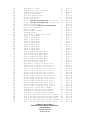
Table Of Contents
REVISION HISTORY ...................................................................................................................... 5
Version 2.00.06.............................................................................................................................................. 5
Version 2.00.05.............................................................................................................................................. 5
Version 2.00.04.............................................................................................................................................. 5
Version 2.00.03.............................................................................................................................................. 5
Version 2.00.02.............................................................................................................................................. 5
Version 2.00.01.............................................................................................................................................. 5
Version 2.00.00.............................................................................................................................................. 5
INTRODUCTION ............................................................................................................................. 6
Overview........................................................................................................................................................ 6
Document Conventions ................................................................................................................................ 6
APPENDIX A, PRESET PARAMETERS........................................................................................ 7
Appendix A Preset Parameter Notes.......................................................................................................... 7
APPENDIX B, SYSTEM PARAMETERS ....................................................................................... 9
Appendix B System Parameter Notes....................................................................................................... 13
RS-232 Feedback Selection set to Reply .................................................................................................. 20
RS-232 Feedback Selection set to Update ................................................................................................ 20
APPENDIX C TUNER STATION PARAMETERS ........................................................................ 22
APPENDIX D REALTIME STATUS PARAMETER...................................................................... 23
APPENDIX E UNIT PARAMETERS ............................................................................................. 24
Appendix E, Unit Info Parameter Notes................................................................................................... 25
APPENDIX F IR COMMANDS ...................................................................................................... 32
APPENDIX G, FRONT PANEL COMMANDS .............................................................................. 34
APPENDIX H, VALID ASCII DISPLAY CHARACTERS .............................................................. 35
CT600.1-3 and CT300.1-3
BKC-DIP Product Specific Appendices
Version 2.00.06
Updated 08/27/09
Page 2 of 59
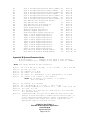
APPENDIX I, SPECIAL DISPLAY CHARACTERS...................................................................... 36
APPENDIX J, ASCII TABLE......................................................................................................... 37
APPENDIX K, LED MAPPING...................................................................................................... 38
APPENDIX L, X (EXECUTIVE) COMMANDS .............................................................................. 39
Recall Preset Command: (receiveID, X, 0, z=nn; cs16)........................................................................... 39
Save Preset Command: (receiveID, X, 1, z=nn, autoNameMode; cs16) ................................................ 39
Power State Command: (receiveID, X, 2, z=onOff; cs16) ....................................................................... 39
Cold Boot Command: (receiveID, X, 6; cs16) .......................................................................................... 40
Factory Reset Command: (receiveID, X, 7; cs16).................................................................................... 40
Reinitialize BKC-DIP State Command: (receiveID, X, 8; cs16) ............................................................. 40
Mute State Command: (receiveID, X, A, z=muteState; cs16)................................................................ 40
Initiate Flashloader Command: (receiveID, X, B; cs16) ......................................................................... 41
Clear Flash Block Command: (receiveID, X, C=xx; cs16)...................................................................... 41
TFTP Client Load Command: (receiveID, X, D; cs16) ........................................................................... 41
Unsupported Executive Commands.......................................................................................................... 41
APPENDIX M, ERROR LOGS ...................................................................................................... 42
Appendix M, Error Logs Parameter Notes .............................................................................................. 42
APPENDIX N, ZONE SPECIFIC PARAMETERS......................................................................... 44
Appendix N, Zone Specific Parameter Notes........................................................................................... 45
APPENDIX O, MACRO PARAMETERS ...................................................................................... 48
Supported Macro Types............................................................................................................................. 48
Serial Macro Parameters ........................................................................................................................... 48
General Notes Regarding Serial Macros .............................................................................................. 48
Serial Macro Parameter Notes .............................................................................................................. 49
APPENDIX P, OVERRIDE PARAMETERS.................................................................................. 56
Appendix P, Override Parameters Notes ................................................................................................. 56
CT600.1-3 and CT300.1-3
BKC-DIP Product Specific Appendices
Version 2.00.06
Updated 08/27/09
Page 3 of 59
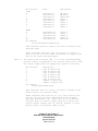
APPENDIX Q, STATUS MESSAGES........................................................................................... 57
APPENDIX R, ZONE ADJUSTMENT PARAMETERS................................................................. 58
Appendix R Zone Adjustment Parameter Notes..................................................................................... 59
CT600.1-3 and CT300.1-3
BKC-DIP Product Specific Appendices
Version 2.00.06
Updated 08/27/09
Page 4 of 59
Revision History
Version 2.00.06
1.
2.
Add Front Panel commands 0x12 and 0x16 - Restore Memory and Backup Memory.
Remove 0x0D - Restore User Preference Memory
Version 2.00.05
3.
4.
5.
6.
7.
Removed re-initialize BKC-DIP Command (FF,X,8;) from the unsupported executive
commands list
Remove System Parameter B5 - Rear Panel to Flasher outs.
Remove System Parameter F9 - System On Specification
Defined executive Bootloader Command (FF,X,B;), Clear Flash Block Command
(FF,X,C=xx;) and TFTP Client Load Command: (FF, X, D;) as commands valid only via an
Ethernet connection
Documented support for executive mute state command (FF,X,A,zz=x;)
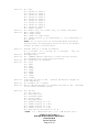
Version 2.00.04
1.
Modify Macro Parameter 0A value note (re-arrange the send type).
Version 2.00.03
1.
Add Parameters 47, 47, 48, 51, and 52 to unit info.
Version 2.00.02
1.
2.
Add “note 8” for Appendix A
Remove System Parameter F9
Version 2.00.01
3.
4.
5.
6.
7.
Add System Parameter FA & FB
Fixed System Parameter C9’s reference note from 28 to 20.
Modify System Parameter Note 28.
Removed System Parameter B5 (Rear Panel to Flasher Outs is no longer supported).
Macro Parameter 0A-0D is not currently supported
Version 2.00.00
1.
The Initial Release of this document, which is referred to as BKC-DIP V2.00.00
documentation.
CT600.1-3 and CT300.1-3
BKC-DIP Product Specific Appendices
Version 2.00.06
Updated 08/27/09
Page 5 of 59
Introduction
Overview
The following is a supplement to B&K Components Device Interface Protocol (BKC-DIP)
Protocol Document. This document contains the specific BKC-DIP implementation details for
B&K Components' CT600.1-3 and CT300.1-3 products.
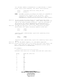
Document Conventions
All numbers are assumed to be hexadecimal. Hexadecimal (or Hex for short) characters range
from 0 to F.
For example:
1
0
The number 19 is the hexadecimal number 19 which is (1 x 16 ) + (9 x 16 ) or
1
25 decimal. Similarly, EA is the hexadecimal number EA which is (14 x 16 ) +
0
(10 x 16 ) or 234 decimal. For clarity, some descriptions regarding numbers
may use the xxh notation to remind the reader that the number is implicitly
hexadecimal where xx are the hexadecimal characters 0 - F. Thus the previous
examples would be 19h and EAh respectively, the "h" indicating hexadecimal.
Maximum values appearing in double quotes indicate that the parameter is an ASCII string.
For example:
"D" for the Z1 Title maximum value indicates that the title is a string with a
maximum length of 0Dh (13 decimal) characters.
Italics indicate a non-literal string.
For example:
(00,G, P00, 0;cs16)
cs16 indicates the calculated checksum and does NOT literally appear in the
data stream.
Important concepts are denoted by NOTE:
CT600.1-3 and CT300.1-3
BKC-DIP Product Specific Appendices
Version 2.00.06
Updated 08/27/09
Page 6 of 59
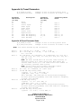
Appendix A, Preset Parameters
(0,G,P1=FF,0;cs16)
(0,S,P1=A,1=24;cs16)
Parameter
Identifier
(in hex)
00
01
02
03
04
05
06
07
08
09
0A
Example of Get Z1 current preset title
Example of Set Z1 Preset 10 volume = 0 dB
Description
Parameter
Max Values
(in hex)
"D"
28
B
B
9
C
C
2
74, 81
67, CD
1
Title
Volume
Source Input
Audio Input
Video Input
Bass Level
Treble Level
Equalization
Tuner AM Frequency
Tuner FM Frequency
Tuner FM Mode
Formatting Notes
Notes
Note
Note
Note
Note
Note
Note
Note
Note
Note
Note
1
3
3
8
2
2
4
5, 5a
6, 6a
7
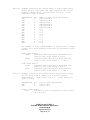
Appendix A Preset Parameter Notes
(0,G,P1=FF,0;cs16)
(0,S,P1=A,1=28;cs16)
Example of Get Z1 current preset title
Example of Set Z1 Preset 10 volume = 0 dB
(NOTE: hex values denoted by xxh convention)
Note 1:
Note 2:
Note 3:
Note 4:
Note 5:
Note 5a:
Note 6:
0h = -80 dB, 1h = -78 dB ... 28h = +0 dB
0h = -12.0 dB, 1h = -10 dB, ... 6h = 0.0 dB, ...
Ch = +12.0 dB
0h = FM Tuner, 1h = AM Tuner, 2h = Dedicated, 3h = In1, 4h =
In2, 5h = In3, 6h = In4, 7h = In5, 8h = In6, 9h = In7, Ah =
In8, Bh = In9
NOTE: FM Tuner and AM Tuner do not have video sources, so
selecting either as a video source will NOT change the
current video source (i.e. the video source will remain on
the currently selected video source).
NOTE: Source Input controls Audio and Video Inputs
simultaneously, keeping them synchronized.
0h = off, 1h = Loudness, 2h = Auto Level
10 kHz AM step tuning (USA)
(((value – 1) * 10) + 520) kHz, or
(((AM_kHz - 520) / 10) + 1) with
2Ah = 930 KHz; 00h indicates an uninitialized frequency.
If tuner stations programmed, last used station's frequency
is used, else 520 kHz.
9 kHz AM step tuning
(((value – 1)* 9) + 522) kHz, or
(((AM_kHz - 522) / 9) + 1) with
2Eh = 927 KHz; 00h indicates an uninitialized station.
If tuner stations programmed, last used station's frequency
is used, else 522 kHz.
200 kHz FM step tuning (USA)
(((value – 1)* 0.20 ) + 87.5) MHz, or
CT600.1-3 and CT300.1-3
BKC-DIP Product Specific Appendices
Version 2.00.06
Updated 08/27/09
Page 7 of 59
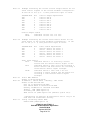
Note 6a:
Note 7:
Note 8:
(((FM_MHz - 87.5) /0.2) + 1) with
4Ch = 102.5 MHz; 00h indicates an uninitialized frequency.
If tuner stations programmed, last used station's frequency
is used, else 87.5 MHz.
100 kHz FM step tuning
(((value – 1)* 0.10 ) + 87.5) MHz, or
(((FM_MHz - 87.5) /0.1) + 1) with 97h = 102.5 MHz; 00h
indicates an uninitialized frequency. If tuner stations
programmed, last used station's frequency
is used, else 87.5 MHz.
0h = Mono, 1h = Stereo
0h = Dedicated
1h = In1
2h = In2
3h = In3
4h = In4
5h = In5
6h = In6
7h = In7
8h = In8
9h = In9
CT600.1-3 and CT300.1-3
BKC-DIP Product Specific Appendices
Version 2.00.06
Updated 08/27/09
Page 8 of 59
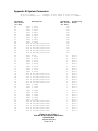
Appendix B, System Parameters
(0,G,S,17;cs16)
(0,S,S,3=”LASER”;cs16)
Parameter
Identifier
(in hex)
00
01
02
03
04
05
06
07
08
09
0A
0B
0C
0D
0E
0F
10
11
12
13
14
15
16
17
18
19
1A
1B
1C
1D
1E
1F
20
21
22
23
24
25
26
27
28
29
2A
2B
2C
2D
Example of Get Input 8 Level Setting
Example of Set Input 4 Title to “LASER”
Description
Input 1 Title
Input 2 Title
Input 3 Title
Input 4 Title
Input 5 Title
Input 6 Title
Input 7 Title
Input 8 Title
Input 9 Title
Zone A IN Dedicated
Zone B IN Dedicated
Zone C IN Dedicated
Zone D IN Dedicated
Zone E IN Dedicated
Zone F IN Dedicated
Tuner Level
Input 1 Level
Input 2 Level
Input 3 Level
Input 4 Level
Input 5 Level
Input 6 Level
Input 7 Level
Input 8 Level
Input 9 Level
Zone A IN Dedicated
Zone B IN Dedicated
Zone C IN Dedicated
Zone D IN Dedicated
Zone E IN Dedicated
Zone F IN Dedicated
Input 1 Video
Input 2 Video
Input 3 Video
Input 4 Video
Input 5 Video
Input 6 Video
Input 7 Video
Input 8 Video
Input 9 Video
Zone A IN Dedicated
Zone B IN Dedicated
Zone C IN Dedicated
Zone D IN Dedicated
Zone E IN Dedicated
Zone F IN Dedicated
Title
Title
Title
Title
Title
Title
Level
Level
Level
Level
Level
Level
Video
Video
Video
Video
Video
Video
Parameter
Max Values
(in hex)
"5"
"5"
"5"
"5"
"5"
"5"
"5"
"5"
"5"
"5"
"5"
"5"
"5"
"5"
"5"
6
6
6
6
6
6
6
6
6
6
6
6
6
6
6
6
1
1
1
1
1
1
1
1
1
1
1
1
1
1
1
CT600.1-3 and CT300.1-3
BKC-DIP Product Specific Appendices
Version 2.00.06
Updated 08/27/09
Page 9 of 59
Formatting
Notes
Note
Note
Note
Note
Note
Note
Note
Note
Note
Note
Note
Note
Note
Note
Note
Note
Note
Note
Note
Note
Note
Note
Note
Note
Note
Note
Note
Note
Note
Note
Note
1
1
1
1
1
1
1
1
1
1
1
1
1
1
1
1
2
2
2
2
2
2
2
2
2
2
2
2
2
2
2
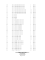
2E
2F
30
31
32
33
34
35
36
37
38
39
3A
3B
3C
3D
3E
3F
40
41
42
43
44
45
46
47
48
49
4A
4B
4C
4D
4E
4F
50
51
52
53
54
55
56
57
58
59
5A
5B
5C
5D
5E
5F
60
61
62
63
64
Zone A IN Dedicated Selection
Zone B IN Dedicated Selection
Zone C IN Dedicated Selection
Zone D IN Dedicated Selection
Zone E IN Dedicated Selection
Zone F IN Dedicated Selection
Zone A IN Dedicated Release Time
Zone B IN Dedicated Release Time
Zone C IN Dedicated Release Time
Zone D IN Dedicated Release Time
Zone E IN Dedicated Release Time
Zone F IN Dedicated Release Time
Zone A Mode
Zone B Mode
Zone C Mode
Zone D Mode
Zone E Mode
Zone F Mode
Zone A Page/Event Selection
Zone B Page/Event Selection
Zone C Page/Event Selection
Zone D Page/Event Selection
Zone E Page/Event Selection
Zone F Page/Event Selection
Zone A Tuner Assignment
Zone B Tuner Assignment
Zone C Tuner Assignment
Zone D Tuner Assignment
Zone E Tuner Assignment
Zone F Tuner Assignment
Zone A Left Level Control
Zone B Left Level Control
Zone C Left Level Control
Zone D Left Level Control
Zone E Left Level Control
Zone F Left Level Control
Zone A Left Max Level
Zone B Left Max Level
Zone C Left Max Level
Zone D Left Max Level
Zone E Left Max Level
Zone F Left Max Level
Zone A Right Level Control
Zone B Right Level Control
Zone C Right Level Control
Zone D Right Level Control
Zone E Right Level Control
Zone F Right Level Control
Zone A Right Max Level
Zone B Right Max Level
Zone C Right Max Level
Zone D Right Max Level
Zone E Right Max Level
Zone F Right Max Level
Group a Code Set ID
CT600.1-3 and CT300.1-3
BKC-DIP Product Specific Appendices
Version 2.00.06
Updated 08/27/09
Page 10 of 59
1
1
1
1
1
1
1A
1A
1A
1A
1A
1A
1
1
1
1
1
1
3
3
3
3
3
3
2
2
2
2
2
2
1
1
1
1
1
1
28
28
28
28
28
28
1
1
1
1
1
1
28
28
28
28
28
28
80
Note
Note
Note
Note
Note
Note
Note
Note
Note
Note
Note
Note
Note
Note
Note
Note
Note
Note
Note
Note
Note
Note
Note
Note
Note
Note
Note
Note
Note
Note
Note
Note
Note
Note
Note
Note
Note
Note
Note
Note
Note
Note
Note
Note
Note
Note
Note
Note
Note
Note
Note
Note
Note
Note
Note
3
3
3
3
3
3
17
17
17
17
17
17
4
4
4
4
4
4
5
5
5
5
5
5
6*
6*
6*
6*
6*
6*
7
7
7
7
7
7
8
8
8
8
8
8
7
7
7
7
7
7
8
8
8
8
8
8
9
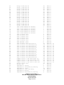
65
66
67
68
69
6A
6B
6C
6D
6E
6F
70
71
72
73
74
75
76
77
78
79
7A
7B
7C
7D
7E
7F
80
81
82
83
84
85
86
87
88
89
8A
8B
8C
8D
8E
8F
90
91
92
93
94
95
96
97
98
99
9A
9B
Group b Code Set ID
Group c Code Set ID
Group d Code Set ID
Group e Code Set ID
Group f Code Set ID
Group g Code Set ID
Group h Code Set ID
Group i Code Set ID
Group j Code Set ID
Group k Code Set ID
Group l Code Set ID
Group m Code Set ID
Group n Code Set ID
Group o Code Set ID
Group p Code Set ID
Group q Code Set ID
Group r Code Set ID
Zone A Rear Remote In Setting
Zone B Rear Remote In Setting
Zone C Rear Remote In Setting
Zone D Rear Remote In Setting
Zone E Rear Remote In Setting
Zone F Rear Remote In Setting
Zone A Control Out
Zone B Control Out
Zone C Control Out
Zone D Control Out
Zone E Control Out
Zone F Control Out
Zone Control 1 Out
Zone Control 2 Out
Zone A Control Out Selected 0-7
Zone A Control Out Selected 8-11
Zone B Control Out Selected 0-7
Zone B Control Out Selected 8-11
Zone C Control Out Selected 0-7
Zone C Control Out Selected 8-11
Zone D Control Out Selected 0-7
Zone D Control Out Selected 8-11
Zone E Control Out Selected 0-7
Zone E Control Out Selected 8-11
Zone F Control Out Selected 0-7
Zone F Control Out Selected 8-11
Common Control 1 Out Select/Act 0-7
Common Control 1 Out Select/Act 8-11
Common Control 2 Out Select /Act 0-7
Common Control 2 Out Select /Act 8-11
RS-232 Control Out
Flasher Out
Page/Event 1 Action
Page/Event 1 Activated by Setting
Page/Event 1 Level
Page/Event 1 Turn off delay
Page/Event 2 Action
Page/Event 2 Activated by Setting
CT600.1-3 and CT300.1-3
BKC-DIP Product Specific Appendices
Version 2.00.06
Updated 08/27/09
Page 11 of 59
80
80
80
80
80
80
80
80
80
80
80
80
80
80
80
80
80
1
1
1
1
1
1
4
4
4
4
4
4
D
D
FF
0F
FF
0F
FF
0F
FF
0F
FF
0F
FF
0F
FF
0F
FF
0F
FF
2
A
4
28
1A
A
4
Note
Note
Note
Note
Note
Note
Note
Note
Note
Note
Note
Note
Note
Note
Note
Note
Note
Note
Note
Note
Note
Note
Note
Note
Note
Note
Note
Note
Note
Note
Note
Note
Note
Note
Note
Note
Note
Note
Note
Note
Note
Note
Note
Note
Note
Note
Note
Note
Note
Note
Note
Note
Note
Note
Note
9
9
9
9
9
9
9
9
9
9
9
9
9
9
9
9
9
10
10
10
10
10
10
11
11
11
11
11
11
25
25
12,
12,
12,
12,
12,
12,
12,
12,
12,
12,
12,
12,
12,
12,
12,
12,
13
26
14
16
8
17
14
16
28
28
28
28
28
28
28
28
28
28
28
28
28
28
28
28
9C
9D
A6
A7
A8
A9
AA
AB
AC
AD
AE
AF
B2
B3
B6
B7
B8
B9
BA
BB
BC
BD
BE
BF
C0
C1
C2
C3
C4
C5
C6
C9
CA
CB
CC
CD
CE
CF
D0
D1
D2
D3
D4
D5
D6
D7
D8
D9
DA
DB
DC
DD
DE
DF
E0
Page/Event 2 Level
Page/Event 2 Turn off delay
Preset Recall Options
Preset Auto Naming
Favorite Preset Recall
RS-232 Port Enabled
RS-232 Baud Rate
Serial (RS-232 and Ethernet) Receive ID
Serial (RS-232 and Ethernet) Transmit ID
RS-232 Echo Enabled
Serial Feedback (RS-232 and Ethernet)
RS-232 V2.0 Enabled
Memory Locked
Advanced Menu Visible
OSD Reply Mode
Front Panel Display Reply Mode
Input 1 Input Mode
Input 2 Input Mode
Input 3 Input Mode
Input 4 Input Mode
Input 5 Input Mode
Input 6 Input Mode
Input 7 Input Mode
Input 8 Input Mode
Input 9 Input Mode
Zone A Dedicated Input Mode
Zone B Dedicated Input Mode
Zone C Dedicated Input Mode
Zone D Dedicated Input Mode
Zone E Dedicated Input Mode
Zone F Dedicated Input Mode
Rear Panel Remote Setting
Page/Event 1 affects Control Out 1
Page/Event 2 affects Control Out 2
Stereo Left Calibrate Level Zone A
Stereo Left Calibrate Level Zone B
Stereo Left Calibrate Level Zone C
Stereo Left Calibrate Level Zone D
Stereo Left Calibrate Level Zone E
Stereo Left Calibrate Level Zone F
Stereo Right Calibrate Level Zone A
Stereo Right Calibrate Level Zone B
Stereo Right Calibrate Level Zone C
Stereo Right Calibrate Level Zone D
Stereo Right Calibrate Level Zone E
Stereo Right Calibrate Level Zone F
Page/Event 1 Assert Macro Number
Page/Event 1 Deassert Macro Number
Page/Event 2 Assert Macro Number
Page/Event 2 Deassert Macro Number
Zone A IN Dedicated Assert Macro Number
Zone A IN Dedicated Deassert Macro Number
Zone B IN Dedicated Assert Macro Number
Zone B IN Dedicated Deassert Macro Number
Zone C IN Dedicated Assert Macro Number
CT600.1-3 and CT300.1-3
BKC-DIP Product Specific Appendices
Version 2.00.06
Updated 08/27/09
Page 12 of 59
28
1A
2
1
1
1
8
7F
7F
1
3
1
1
1
2
2
1
1
1
1
1
1
1
1
1
1
1
1
1
1
1
1
1
1
C
C
C
C
C
C
C
C
C
C
C
C
FF
FF
FF
FF
FF
FF
FF
FF
FF
Note
Note
Note
Note
Note
Note
Note
Note
Note
Note
Note
Note
Note
Note
Note
Note
Note
Note
Note
Note
Note
Note
Note
Note
Note
Note
Note
Note
Note
Note
Note
Note
Note
Note
Note
Note
Note
Note
Note
Note
Note
Note
Note
Note
Note
Note
Note
Note
Note
Note
Note
Note
Note
Note
Note
8
17
36
2
19
20
21
22
22
20
34
20
2
23
27
27*
4
4
4
4
4
4
4
4
4
4
4
4
4
4
4
20
2
2
29
29
29
29
29
29
29
29
29
29
29
29
30
30
30
30
30
30
30
30
30
E1
E2
E3
E4
E5
E6
E7
E8
E9
EA
EB
EC
ED
EE
EF
F0
F1
F2
F3
F4
F5
F6
F7
F8
FA
FB
Zone C IN Dedicated Deassert Macro Number
Zone D IN Dedicated Assert Macro Number
Zone D IN Dedicated Deassert Macro Number
Zone E IN Dedicated Assert Macro Number
Zone E IN Dedicated Deassert Macro Number
Zone F IN Dedicated Assert Macro Number
Zone F IN Dedicated Deassert Macro Number
Auto BKC-DIP Set IR Generate Enable
Auto BKC-DIP Set IR Mask
Auto BKC-DIP Set IR Transmit ID
Page/Event Activation Bitmap
RS232 Keypad Receive ID
FM RS232 Keypad Page/Device
AM RS232 Keypad Page/Device
Dedicated RS232 Keypad Page/Device
Input 1 RS232 Keypad Page/Device
Input 2 RS232 Keypad Page/Device
Input 3 RS232 Keypad Page/Device
Input 4 RS232 Keypad Page/Device
Input 5 RS232 Keypad Page/Device
Input 6 RS232 Keypad Page/Device
Input 7 RS232 Keypad Page/Device
Input 8 RS232 Keypad Page/Device
Input 9 RS232 Keypad Page/Device
Rear Panel IR Routing Bitmap LSBits
Rear Panel IR Routing Bitmap MSBits
FF
FF
FF
FF
FF
FF
FF
1
3F
80
3
FF
B4
B4
B4
B4
B4
B4
B4
B4
B4
B4
B4
B4
FF
3F
Note
Note
Note
Note
Note
Note
Note
Note
Note
Note
Note
Note
Note
Note
Note
Note
Note
Note
Note
Note
Note
Note
Note
Note
Note
Note
30
30
30
30
30
30
30
20
31
24
35
32
33
33
33
33
33
33
33
33
33
33
33
33
38, 39
38, 39
Appendix B System Parameter Notes
(0,G,S,17;cs16)
(0,S,S,3=”LASER”;cs16)
Example of Get Input 9 Level Setting
Example of Set Input 4 Title to “LASER”
(NOTE: hex values denoted by xxh convention)
Note
Note
Note
Note
Note
Note
1:
2:
3:
4:
5:
6:
0h
0h
0h
0h
0h
0h
= -6.0 dB, 2h = -4.0 dB, ... 3h = 0.0 dB, ... 6h = +6.0 dB
= No, 1h = Yes
= Manual, 1h = Auto
= Mono, 1h = Stereo
= None, 1h = Page/Event 1, 2h = Page/Event 2, 3h = Both
= Tuner 1, 1h = Tuner 2, 2h = Tuner 3
*NOTE: No of Tuners, 1 in CTxxx.1, 2 in CTxxx.2
and 3 in CTxxx.3
Note
Note
Note
Note
Note
7: 0h = Fixed, 1h = Variable
8: 0h = -80 MUTE dB, 1h = -78 dB ... 28h = +0 dB
9: 0h = Group Disabled, 1h = Zone ID of 1, … 80h = Zone ID of 128
10: 0h = Off, 1h = On,
11: 0h = RS-232, 1h = Zone On, 2h = Zone Active, 3h = Zone Off,
4h = Selected Input
Note 12: (represents LSB, see note 28 for MSB) Set Zone Control Out
setting to Selected Input or Common Control Active Input, a 1
in the following bitmap position (which corresponds to the
various inputs) will assert the control output when the
appropriate input is selected (active):
CT600.1-3 and CT300.1-3
BKC-DIP Product Specific Appendices
Version 2.00.06
Updated 08/27/09
Page 13 of 59
Bit Position
(LSB)
0
1
2
3
4
5
6
7
Word
Selected
Selected
Selected
Selected
Selected
Selected
Selected
Selected
Description
0-7
0-7
0-7
0-7
0-7
0-7
0-7
0-7
(MSB)
0
Selected 8-11
1
Selected 8-11
2
Selected 8-11
3
Selected 8-11
4-7
Selected 8-11
For example,
(0,S,S,7E=4,88=01,89=04;cs16)
FM Tuner
AM Tuner
Dedicated
Input 1
Input 2
Input 3
Input 4
Input 5
Input 6
Input 7
Input 8
Input 9
Reserved
7E=4 indicates Zone C’s control out state is based on the
Selected Input
88=01 and 89=04 indicates that the control out state of
Zone C will be on if the input is AM Tuner or Input 8, and
off for all other selected inputs.
Note 13:
Set Control Out to RS-232 (0h), a 1 in the following bitmap
position (which corresponds to the various inputs) will assert
the control output when the appropriate input is selected:
Bit Position
Description
0
Zone A Control Out
1
Zone B Control Out
2
Zone C Control Out
3
Zone D Control Out
4
Zone E Control Out
5
Zone F Control Out
6
Common 1 Control Out
7
Common 2 Control Out
For example,
(0,S,S,7E=0,94=04;cs16)
7E=0 indicates Zone C’s control out state is based on the
RS-232 Control out register (94h)
94=04 indicates that Zones A, B, D, E, and F control out
will be off (only if their appropriate Control Output
settings (identifiers 7Ch – 81h) are set to use RS-232),
and that Zone C’s control output would be On (since its
Control Output setting 74h = 0, RS-232) and bit 2 of the
RS-232 Control out register (94h) is set.
CT600.1-3 and CT300.1-3
BKC-DIP Product Specific Appendices
Version 2.00.06
Updated 08/27/09
Page 14 of 59
Note 14:
Note 15:
Note 16:
Note 17:
Note 18:
Note 19:
Note 20:
Note 21:
Note 22:
Note 23:
Note 24:
Note 25:
0h = Off
1h = switch to Input 1
2h = switch to Input 2
3h = switch to Input 3
4h = switch to Input 4
5h = switch to Input 5
6h = switch to Input 6
7h = switch to Input 7
8h = switch to Input 8
9h = switch to Input 9
Ah = Reduce Volume
0h = Audio only, 1h = Video only, 2h = Audio and Video
*0h = Audio sense
*1h = Video sense
*2h = Audio or Video sense
3h = Common Control (1 for Page/Event 1, 2 for Page/Event 2)
4h = RS-232
*Note: 0h, 1h and 2h are not valid Page/Event Activation
settings while the Page/Event Action is set to Ah “Reduce
Volume” see Note 14 listed above.
Release Time in 1 second increments.
0h = 0 seconds, 1h = 1 second, 2h = 2 seconds, … 19h = 25
seconds, 1Ah = forever
Not Applicable.
0h = “ENTER” Button required to recall Favorite Preset,
1h = Automatically recall Favorite Preset
0h = Disabled, 1h = Enabled
0h = 1200
1h = 2400
2h = 9600
3h = 14400
4h = 19200
5h = 28800
6h = 38400
7h = 57600
8h = 115200
Valid IDs are 00h to 7Fh. Receive IDs must be unique (to
avoid ambiguity)
0h = Hidden, 1h = Visible
00h to 7Fh map directly to Transmit IDs 00h to 7Fh. 80h maps
to the Global Transmit ID FFh.
0h = RS-232
1h = Any Zone On
2h = All Zones Off
3h = Selected Input
4h = Active Input
5h = Not Applicable.
6h = Common Control In 1 On
7h = Common Control In 1 Off
8h = Common Control In 2 On
9h = Common Control In 2 Off
Ah = Any Zone On OR Control In X* On
* NOTE: X = 1 Control Out 1, X = 2 Control Out 2
CT600.1-3 and CT300.1-3
BKC-DIP Product Specific Appendices
Version 2.00.06
Updated 08/27/09
Page 15 of 59
NOTE:
NOTE:
Note 26:
Note 27:
Note 28:
Note 29:
Note 30:
Note 31:
Common Control 2 not valid for a CT300.1-3.
Values 8h = Common Control In 2 On and 9h = Common
Control In 2 Off are not valid for CT300.1-3.
0h = Off, 1h = Selected Input, 2h = All Inputs
0h = BKC-DIP V1.0 compliant, 1h = BKC-DIP V2.0 compliant with
no attributes, 2h = BKC-DIP V2.0 compliant with attributes
NOTE: This parameter is reset to 0h after a cold/warm boot.
(represents MSB continuation for MSB bit map value)
See note 12
0h = -12.0 dB, 1h = -10 dB, ... 6h = 0.0 dB, ...
Ch = +12.0 dB
NOTE: The Stereo Left/Right Calibration Level is ignored by
the unit when it’s corresponding Zone Mode is set to
Mono.
0h = Serial Macro 0, 1h = Serial Macro 1, … FDh = Serial
Macro 253, FEh = Serial Macro 254, FFh = No Macro.
NOTE: If there is no corresponding valid Serial Macro, the
end result is the same as if set to FFh = No Macro.
Bitmap indicating which Hardware Zones (Zones A, B, C, D, E
or F) to allow RS-232 data to be output. If the bit is set,
the data will be output.
Zone
Zone
Zone
Zone
Zone
Zone
A
B
C
D
E
F
01h
02h
04h
08h
10h
20h
Thus an output mask of 2Bh would allow serial port data to be
output on Zone A, Zone B, Zone D and Zone F, but NOT on Zone C
and Zone E.
NOTE:
Note 32:
The serial port data is always transmitted out the
“primary” serial port connection, i.e. the RJ45
connector. An output mask of 00h will mask all data to
the Hardware Zone outputs, but the data will still be
transmitted to the primary serial port.
0h = 0, 1h = 1, … FDh = 253, FEh = 254, FFh = Global Receive
ID. Note: while a Zone is set for MONO operation, all RS-232
feedback status messages use ID 0 for Mono Left and ID 1 and
for Mono Right. Please set the Keypad or feedback reception ID
correctly for use with MONO zone operation.
CT600.1-3 and CT300.1-3
BKC-DIP Product Specific Appendices
Version 2.00.06
Updated 08/27/09
Page 16 of 59
Note 33:
Page and Device are merged together into a single byte, where
Page occupies the 3 most significant bits, and Device occupies
the 5 least significant bits:
ppp ddddd
The maximum valid page is 4h (Page 5).
The maximum valid device is 13h (Device 20).
00h
01h
02h
:
13h
14h
15h
= Main 1, Device None
= Main 1, Device 1
= Main 1, Device 2
:
:
= Main 1, Device 19
= Main 1, Device 20
– 1Fh = invalid Page/Device combination
20h
21h
22h
:
33h
34h
35h
= Main 2, Device None
= Main 2, Device 1
= Main 2, Device 2
:
:
= Main 2, Device 19
= Main 2, Device 20
– 3Fh = invalid Page/Device combination
40h
41h
42h
:
53h
54h
55h
= Page 1, Device None
= Page 1, Device 1
= Page 1, Device 2
:
:
= Page 1, Device 19
= Page 1, Device 20
– 5Fh = invalid Page/Device combination
60h
61h
62h
:
73h
74h
75h
= Page 2, Device None
= Page 2, Device 1
= Page 2, Device 2
:
:
= Page 2, Device 19
= Page 2, Device 20
– 7Fh = invalid Page/Device combination
80h
81h
82h
:
93h
94h
95h
= Page 3, Device None
= Page 3, Device 1
= Page 3, Device 2
:
:
= Page 3, Device 19
= Page 3, Device 20
– 9Fh = invalid Page/Device combination
A0h = Page 4, Device None
CT600.1-3 and CT300.1-3
BKC-DIP Product Specific Appendices
Version 2.00.06
Updated 08/27/09
Page 17 of 59
A1h
A2h
:
B3h
B4h
= Page 4,
= Page 4,
:
= Page 4,
= Page 4,
Device 1
Device 2
:
Device 19
Device 20
Decomposing one of the above for clarification:
53h = Page 1, Device 19
53h = 010 10011 binary
Page = Most significant 3 bits: 010 binary, 2h = Page 3
(Note Page is offset by 1)
Device = Least significant 5 bits: 10010 binary, 12h =
Device 19 (Note Device is offset by 1).
Note 34:
0h = Disabled, 1h = Update, 2 = Reply, 3 = Both (Update and
Reply). Note: while a Zone is set for MONO operation, all RS232 feedback status messages use ID 0 for Mono Left and ID 1
and for Mono Right. Please set the Keypad or feedback
reception ID correctly for use with MONO zone operation.
Note 35: Bitmap indicating state Page/Events via BKC-DIP. If the bit
is set, the Page/Event will be asserted, if it is clear the
Page/Event will be deasserted. Note: assumes the Page/Event
Activated System Parameter (97 or 9B) is set 4 (use RS-232).
Page/Event 1
Page/Event 2
01h
02h
enabled if 97h is set to 4
enabled if 9Bh is set to 4
Note 36: 0h = Input/Tone, 1h = Input/Tone/Volume, 2h = Input Only
Note 37: 0h
1h
2h
3h
Note 38:
=
=
=
=
Any
Any
Any
Any
Zone
Zone
Zone
Zone
(represents
Router, a 1
corresponds
output when
On
On OR Control In 1 On
On OR Control In 2 On
On OR Control In 1 On OR Control In 2 On
LSB, see note 39 for MSB) Set Rear Panel IR
in the following bitmap position (which
to the various inputs) will assert the control
the appropriate input is selected (active):
Bit Position
(LSB)
0
1
2
3
4
5
6
7
Word
Selected
Selected
Selected
Selected
Selected
Selected
Selected
Selected
Description
0-7
0-7
0-7
0-7
0-7
0-7
0-7
0-7
unused (FM)
unused (AM)
unused (dedicated)
IR 1
IR 2
IR 3
IR 4
IR 5
(MSB)
CT600.1-3 and CT300.1-3
BKC-DIP Product Specific Appendices
Version 2.00.06
Updated 08/27/09
Page 18 of 59
0
Selected 8-13
IR 6
1
Selected 8-13
IR 7
2
Selected 8-13
IR 8
3
Selected 8-13
IR 9
4
Selected 8-13
IR All
5
Selected 8-13
RP local control of CT
6
reserved
7
reserved
Note 39: (represents MSB continuation for MSB bit map value)
See note 38
CT600.1-3 and CT300.1-3
BKC-DIP Product Specific Appendices
Version 2.00.06
Updated 08/27/09
Page 19 of 59
RS-232 Feedback Selection set to Reply
Continuous Parameter Feedback
With firmware 2.01 and greater, System Parameter AE has been
changed to RS-232 Feedback Selection. Setting the RS-232
Feedback Selection to “Reply” allows the CT600.1-3/300.1-3 to
automatically generate BKC-DIP Reply messages for changes to
Volume,
Bass,
Treble,
Equalization,
Source
and
Tuner
Frequency.
Below is an example of how the RS-232 Feedback Selection Reply
may be used as Volume Feedback from the CT600.1-3/300.1-3 for
use with an external controller.
Step 1)
First, set the CT600.1-3/300.1-3 system parameter AE = 2,
RS-232 Feedback Selection set to Reply.
Next, initiate a Master Volume change by one of the following
methods:
B&K code set 11 (Logical Zone 11) IR Master Volume Up
B&K code set 11 (Logical Zone 11) IR Master Volume Down
Front Panel Volume Encoder up or down while set to Logical
Zone 11
The CT600.1-3/300.1-3 will automatically generate the
following BKC-DIP Reply message command:
(0,R,P0B=FF,1=28;) Logical Zone 11 current Preset Parameter
Volume value is set to 28 hex or 0dB (assumes 0dB is the
current setting).
Step 2)
The external control device should be set to Poll for any BKCDIP Reply messages and parse out the specific logical zone and
current Preset Parameter value of interest, in this case the
current Preset Parameter Volume value for Zone 11.
Step 3)
The external controller should use the CT600.1-3/300.1-3 Zone
11 current Preset Parameter Volume value of “28” hex to update
its GUI or status in an appropriate fashion.
RS-232 Feedback Selection set to Update
Previous to 2.01, BKC-DIP messages “Update”, “Get” and “Reply”
commands were necessary for feedback. All current preset
parameters for all logical zones in the CT600.1-3/300.1-3 are
available at anytime. Typically, an external controller will
use the Update message generated in response to a Front Panel
button press or received B&K IR code-set, to formulate a BKCDIP Get command. The returned BKC-DIP Reply message data may
be used to extract the desired current Preset Parameter(s) and
value(s) for use with updating its display requirements.
CT600.1-3 and CT300.1-3
BKC-DIP Product Specific Appendices
Version 2.00.06
Updated 08/27/09
Page 20 of 59
Below is an example of how the RS-232 Feedback Selection
Update may be used to allow Volume Feedback from the CT600.13/300.1-3 for use with an external controller.
Step 1)
First, set the CT600.1-3/300.1-3 System Parameter AE = 1, RS232 Feedback Selection set to Update.
Next, initiate a Master
following methods:
Volume
change
by
any
one
of
the
B&K code set 11 (Logical Zone 11) IR Master Volume Up B&K code
set 11 (Logical Zone 11) IR Master Volume Down Front Panel
Volume Encoder up or down while set to Logical Zone 11
Using an IR remote control set to B&K code set 11 (Logical
Zone 11) a user presses the Master Volume + (Up) button.
The CT600.1-3/300.1-3 will generate the following BKC-DIP
Update message command:
(0,U,I,0B=C4;) Update from Zone 11 via an IR message.
Step 2)
The external control device should be set to Poll for any BKCDIP Update messages and parse out the specific BKC-DIP message
of interest, in this case a Zone 11, IR Master Volume + (1=C4)
“U,I,0B=C4”. Note if another means of Master Volume up is
used, such as the Front Panel Encoder Up, this would require a
different message “U,F,0B=0B”.
Step 3)
The external controller should generate a CT600.1-3/300.1-3
Get command for the specific current Preset Parameter of
interest, in this case the current Preset Parameter Volume
value. The command would look like the following BKC-DIP Get
message:
(0,G,P0B=FF,1;) Get Zone 11 Volume setting.
Step 4)
Once the CT600.1-3/300.1-3 receives the above Get message it
will generate a Reply message with the requested parameter, in
this case the Reply for the current Preset Parameter Volume
value for Zone 11. The command would look like the following
BKC-DIP Reply message command:
(0,R,P0B=FF,1=28;) Zone 11 current Preset Volume value is set
to 28 hex or 0dB.
Step 5)
The external controller may then use the CT600.1-3/300.1-3
Zone 11 current Preset Parameter Volume value of “28” hex to
update its GUI or status in an appropriate fashion.
In addition to RS-232 Feedback Selections of Update and Reply,
Disable and Both (Update and Reply) allow further versatility
to set the best interface for the CT600.1-3/300.1-3 to an
external controller.
CT600.1-3 and CT300.1-3
BKC-DIP Product Specific Appendices
Version 2.00.06
Updated 08/27/09
Page 21 of 59
Appendix C Tuner Station Parameters
Tuner stations are not supported in the CT600.1-3/300.1-3.
CT600.1-3 and CT300.1-3
BKC-DIP Product Specific Appendices
Version 2.00.06
Updated 08/27/09
Page 22 of 59
Appendix D Realtime Status Parameter
Real-time Status Parameters are not currently supported in the CT600.1-3/300.1-3.
CT600.1-3 and CT300.1-3
BKC-DIP Product Specific Appendices
Version 2.00.06
Updated 08/27/09
Page 23 of 59
Appendix E Unit Parameters
(0,G,F4,0;cs16)
(0,G,F4,1;cs16)
(0,G,F4,C;cs16)
Parameter
Identifier
(in hex)
00
01
02
06
07
08
09
0C
0D
10
11
12
13
14
15
16
17
18
19
1A
1B
1C
1D
1E
1F
20
21
22
23
24
25
26
27
28
29
2A
2B
2C
2D
2E
2F
30
40
41
42
Example of Get Unit Name
Example of Get Version
Example of Get Active BKC-DIP Version
Description
Notes
Unit name
Version
Zone Description
Amplifier Description
Video Scan Rate (NTSC/PAL)
AM steps 9kHz/10kHz
FM steps 100kHz/200kHz
Active BKC-DIP Version
Software Time Stamp
Serial Number
Highest BKC-DIP Version Available
Active Logical Zone Numbers
Number of Inputs
Number of Zones
Number of Dedicated Inputs
Number of Tuners
Number of Control Outputs
Number of Control Inputs
Number of Page/Events
Number of Input Boards
Number of Output Boards
Number of External Inputs
Number of Zones and Detectors
Receive ID
Transmit ID
Input Bitmap LSB
Input Bitmap MSB
Output Bitmap LSB
Output Bitmap LSB
Dedicated Input Bitmap LSB
Dedicated Input Bitmap LSB
Serial Macro Free Space MSB
Serial Macro Free Space LSB
RF Remote
Group Code Set List
Audio Input Detect Bitmap LSB
Audio Input Detect Bitmap MSB
Video Input Detect Bitmap LSB
Video Input Detect Bitmap MSB
Control Input Detect Bitmap
Control Output Status Bitmap
Tuner Detect Status Bitmap
MAC Address
IP Address
Subnet Mask
Note
Note
Note
Note
Note
Note
Note
Note
Note
Note
Note
Note
Note
Note
Note
Note
Note
Note
Note
Note
Note
Note
Note
Note
Note
Note
Note
Note
Note
Note
Note
Note
Note
Note
Note
Note
Note
Note
Note
Note
Note
Note
Note
Note
Note
CT600.1-3 and CT300.1-3
BKC-DIP Product Specific Appendices
Version 2.00.06
Updated 08/27/09
Page 24 of 59
1
2
3
4
5
6
7
8
9
10
11
12
13
14
15
16*
17
18
19
20
21
22
23
24
24
25
25
26
26
27
27
28
28
29
30
31
31
31
31
32
33
34
35
36**
36**
43
44
45
46
47
48
51
52
Gateway
Host Name
Domain / Workgroup
Primary DNS
Secondary DNS
Use DHCP
TFTP Server IP Address
TFTP Server File Name
Note
Note
Note
Note
Note
Note
Note
Note
36**
37**
37**
36**
36**
39**
36**
38**
** Read/Write Unit Info Parameters.
(0,S,F4,48=1;)
Example of Set to use DHCP
Appendix E, Unit Info Parameter Notes
Note
Note
Note
Note
Note
Note
Note
Note
1:
2:
3:
4:
5:
6:
7:
8:
String indicating Name
String indicating software version
String indicating Zone capabilities
String describing amplifier capabilities
String describing Video scan rate (“NTSC” or “PAL”)
String describing AM Step size (“9kHz” or “10kHz”)
String describing FM Step size (“100kHz” or “200kHz”)
String describing currently active BKC-DIP version.
This may not necessarily be the most sophisticated (highest)
version of BKC-DIP the device can support, but the unit can be
forced to communicate using older more restrictive forms of
BKC-DIP for backwards compatibility.
Note 9: String indicating date/time which software was compiled
Note 10: String containing Unit’s Serial Number
Note 11: String indicating highest BKC-DIP version unit can support.
This can be different than the currently active BKC-DIP
version, as the unit can be forced to communicate using older
more restrictive forms of BKC-DIP for backwards compatibility.
Note 12: String containing list of all active Logical Zone Numbers in
the unit. Each logical zone is delimited by white space, and
the values are in hexadecimal.
For example:
“0 1 2 3 4 5 6 7”
indicates that there are 8 Logical zones, 0-7 currently
present in the unit.
Note
Note
Note
Note
Note
Note
Note
Note
Note
Note
13:
14:
15:
16:
17:
18:
19:
20:
21:
22:
As another example
“0 3 6 9 C 1D”
indicates that there are 6 Logical zones (0h, 3h, 6h, 9h, Ch,
and 1Dh) currently present in the unit.
Number of Inputs (including AM and FM if any tuners present)
Number of Hardware Zones (CT600.1-3 = 6, CT300.1-3 = 3)
Number of Dedicated Inputs(CT600.1-3 = 6, CT300.1-3 = 3)
Number of Tuners (could be 0) *(max 3 in CT600.3/300.3)
Number of Control Outputs
Number of Control Inputs
Number of Page/Events
(CT600.1-3 = 2, CT300.1-3 = 1)
Number of Input Boards
Number of Output Boards
(CT600.1-3 = 2, CT300.1-3 = 1)
Number of External Inputs (excluding AM and FM)
CT600.1-3 and CT300.1-3
BKC-DIP Product Specific Appendices
Version 2.00.06
Updated 08/27/09
Page 25 of 59
Note 23:
Note 24:
Note 25:
Number of Zones and Detectors
Current Serial (RS-232 and Ethernet) Receive/Transmit ID,
shadows System setting
Bitmaps indicating which inputs are valid with the current
hardware configuration. If the bit is set (i.e. 1) that
particular input is valid.
LSB/MSB Word
LSB
LSB
LSB
LSB
LSB
LSB
LSB
LSB
MSB
MSB
MSB
MSB
Bit
0
1
2
3
4
5
6
7
0
1
2
3
Input Represented
FM
AM
Zone Dedicated IN
In 1
In 2
In 3
In 4
In 5
In 6
In 7
In 8
In 9
For example, a fully loaded CT600.3 (3 input boards, 2 output
boards, and 3 tuner modules) would have the following return
values:
20=FF
valid
21=F
Indicates FM, AM, Zone Dedicated IN, In 1-5
Indicates In 6-9 valid
In a minimal CT600.0 configuration (2 input boards, 1 output
board, and no tuner modules), the return value would be
Note 26:
20=FC
Indicates Zone Dedicated Input and In 1-5
valid, No FM, AM
21=01
Indicates In 6 valid, No In 7-9
Bitmaps indicating which outputs are valid with the current
hardware configuration. If the bit is set (i.e. 1) that
particular output is valid.
LSB/MSB Word
LSB
LSB
LSB
LSB
LSB
LSB
LSB
LSB
Bit
0
1
2
3
4
5
6
7
Output Represented
Zone A
Zone B
Zone C
Zone D
Zone E
Zone F
unused
unused
For example, a fully loaded CT600.3 (3 input boards, 2 output
boards, and 3 tuner modules) would have the following return
values:
22=3F
23=0
Indicates Zones A-F valid
Always 0
CT600.1-3 and CT300.1-3
BKC-DIP Product Specific Appendices
Version 2.00.06
Updated 08/27/09
Page 26 of 59
In a minimal CT600.0 configuration (2 input boards, 1 output
board, and no tuner modules), the return value would be
22=07
23=00
NOTE:
Note 27:
Note 28:
Indicates Zones A-C valid, No D-F
Always 0
The MSB currently is always 0 as there is a maximum of
6 possible Zone outputs in the CT series. This
parameter is provided in the protocol for future
expandability should there be more than 8 Zone outputs.
In the current CT series there is a Dedicated Zone input
associated with each Zone Output. Thus, these values are the
same as the Output Bitmap parameters. They are provided in
the protocol for future expandability should there be a
difference between Zone Dedicated inputs and Zone Outputs.
The MSB and LSB form a 16 bit value indicating how much
Serial Macro free space currently remains in the unit.
26=8
27=0
(MSB)
(LSB)
Indicates 800h (2048 decimal) bytes free remaining serial
macro space.
26=1
27=E4
(MSB)
(LSB)
Indicates 1E4h (484 decimal) bytes free remaining serial macro
space.
Note 29: 0h = No RF Remote support, 1h = RF Remote supported
Note 30: String containing list of all Group Code Sets (Zone IDs)in the
unit. Each Code Set (Zone ID) is delimited by white space,
and the values are in hexadecimal.
For example:
“0 B C D E F 10 0 0 0 0 0 0 0 0 0 0”
indicates that there are 17 Groups with Code Sets (Zone IDs):
Group
0
a
b
c
d
e
f
g
h
i
j
k
l
m
Code Set (Zone ID)
0h
3h
4h
Bh
Ch
Dh
Eh
10h
0h
0h
0h
0h
0h
0h
CT600.1-3 and CT300.1-3
BKC-DIP Product Specific Appendices
Version 2.00.06
Updated 08/27/09
Page 27 of 59
n
o
p
q
r
0h
0h
0h
0h
0h
CT600.1-3 and CT300.1-3
BKC-DIP Product Specific Appendices
Version 2.00.06
Updated 08/27/09
Page 28 of 59
Note 31:
Bitmaps indicating the current Audio or Video Input Detect
status for all valid audio and video inputs in the current
hardware configuration. If the bit is set (i.e. 1) that
particular input is valid.
LSB/MSB Word
LSB
LSB
LSB
LSB
LSB
LSB
LSB
LSB
MSB
MSB
MSB
MSB
MSB
MSB
MSB
Bit
0
1
2
3
4
5
6
7
0
1
2
3
4
5
6
Audio or Video Input Represented
Dedicated IN A
Dedicated IN B
Dedicated IN C
Dedicated IN D
Dedicated IN E
Dedicated IN F
In 1
In 2
In 3
In 4
In 5
In 6
In 7
In 8
In 9
For example, a fully loaded CT600.3 (3 input boards, 2 output
boards, and 3 tuner modules) would have the following return
values:
Note 32:
Audio Input Detect
2A=FF
Indicates audio
Inputs A thru F
2B=1F
Indicates audio
Inputs A thru F
detected on Dedicated Zone
and Inputs 1 thru 9
detected on Dedicated Zone
and Inputs 1, 2, and 3.
Video Input Detect
2C=FF
Indicates video
Inputs A thru F
2D=1F
Indicates video
Inputs A thru F
detected on Dedicated Zone
and Inputs 1 thru 9
detected on Dedicated Zone
and Inputs 1, 2, and 3.
Bitmaps indicating the current Control Input Detect Status
for all valid control inputs in the current hardware
configuration. If the bit is set (i.e. 1) that particular
input is valid.
LSB/MSB Word
LSB
LSB
Bit
0
1
Control Input Represented
Control IN 1
Control IN 2
Control Input Detect
2E=3
Indicates control in detected on both Control
IN 1 and IN 2.
CT600.1-3 and CT300.1-3
BKC-DIP Product Specific Appendices
Version 2.00.06
Updated 08/27/09
Page 29 of 59
Note 33:
Bitmaps indicating the current Control Output Status for all
valid control outputs in the current hardware configuration.
If the bit is set (i.e. 1) that particular input is valid.
LSB/MSB Word
LSB
LSB
LSB
LSB
LSB
LSB
LSB
LSB
Bit
0
1
2
3
4
5
6
7
Control
Control
Control
Control
Control
Control
Control
Control
Control
Output Represented
OUT A
OUT B
OUT C
OUT 1
OUT D
OUT E
OUT F
OUT 2
Control Output Status
2F=8
Indicates control out 1 is set.
2F=F0
Indicates control out 2 is set.
Note 34:
Bitmaps indicating the current Tuner Detect Status for all
valid tuners in the current hardware configuration. If the
bit is set (i.e. 1) that particular input is valid.
LSB/MSB Word
LSB
LSB
LSB
LSB
LSB
LSB
Note 35:
Note 36:
Note 37:
Bit
0
1
2
3
4
5
Tuner Status Represented
Station Detect for Tuner
Stereo Detect for Tuner
Station Detect for Tuner
Stereo Detect for Tuner
Station Detect for Tuner
Stereo Detect for Tuner
1
1
2
2
3
3
Tuner Input Detect
30=3
Indicates Tuners 1 is receiving a Stereo
station and the Station Detect signal is set.
30=F
Indicates Tuners 1 and 2 are both receiving a
Stereo station and both tuners are receiving a
valid Station Detect signal strength.
30=3F
Indicates Tuners 1 and 2 and 3 are all
receiving a Stereo station and the Tuners are
receiving a valid Station Detect signal
strength.
Unit’s MAC Address
Format is xx:xx:xx:xx:xx:xx
IP Address / Subnet Mask / Gateway / DNS format
Format as xxx.xxx.xxx.xxx
Unit IP is obtained from DHCP
Unit Subnet Mask is obtained from DHCP
Gateway IP Address is obtained from DHCP
Primary
DNS (DHCP Option 6)
Secondary DNS (DHCP Option 6)
TFTP Server IP (DHCP Option 150 (default option 54))*
* Assigned by an external PC application and is only to be
used with the flashloader utility.
String containing Domain Name
Domain Name (DHCP Option 15)
CT600.1-3 and CT300.1-3
BKC-DIP Product Specific Appendices
Version 2.00.06
Updated 08/27/09
Page 30 of 59
Note 38:
String containing TFTP File Name *
Note 39:
* Assigned by an external PC application and is only to be
used with the flashloader utility.
0h = Off (use static IP address), 1h = On (get IP from DHCP)
CT600.1-3 and CT300.1-3
BKC-DIP Product Specific Appendices
Version 2.00.06
Updated 08/27/09
Page 31 of 59
Appendix F IR Commands
(0,S,I,1=2;cs16)
(0,S,I,1=24;cs16)
IR Command
(in hex)
02
04
0C
IR Description
14
15
16
17
18
19
1A
1B
1D
1E
ALL B&K
ALL B&K
ALL B&K
ALL B&K
STATION
ALL B&K
ALL B&K
ALL B&K
ALL B&K
ALL B&K
21
22
24
38
3F
40
41
42
43
45
48
4C
52
54
5A
5B
5C
5D
5E
5F
60
63
65
66
6C
6E
70
71
74
76
7C
80
8C
90
94
9C
9E
9F
Example of Set Zone 1 IR Save
Example of Set Zone 1 IR Volume +
SAVE
(BALANCE) RIGHT
ENTER
POWER OFF
POWER ON
VOL DOWN
VOL UP
+
0 dB VOL
-20 dB VOL
-40 dB VOL
-60 dB VOL
MUTE
TUNER 2
TUNER 3
MASTER VOL +
TUNE +
OSD MENU 1
POWER ON
OSD MENU 2
OSD MENU 3
OSD MENU 4
POWER (TOGGLE)
FREQ
2
INPUT 6
EQ
ZONE_DIRECT_INPUT
ANALOG SOURCE 8
ANALOG SOURCE +
VIDEO SOURCE VIDEO SOURCE +
INPUT 3
PRESET SOURCE SOURCE +
5
AM
TUNER 1
FM
UP
INPUT 9
0
POWER OFF
1
INPUT 2
+10
7
TREBLE TREBLE +
CT600.1-3 and CT300.1-3
BKC-DIP Product Specific Appendices
Version 2.00.06
Updated 08/27/09
Page 32 of 59
A0
A6
A7
AC
B0
B4
BE
C0
C4
C8
CC
CD
CF
D0
D1
D2
D7
D8
DC
E0
E8
EC
F0
F1
F2
F3
F4
F8
FC
INPUT 1
BASS
BASS
+
4
INPUT 4
DOWN
EXIT
MUTE
MASTER VOL BAND
3
SLEEP
RIGHT
INPUT 7
LEFT
PRESET +
STEREO / MONO
TUNE 9
INPUT 8
STATION 6
INPUT 5
MUTE ON
MUTE OFF
LOUDNESS (TOGGLE)
MENU
(BALANCE) LEFT
ZONE
CT600.1-3 and CT300.1-3
BKC-DIP Product Specific Appendices
Version 2.00.06
Updated 08/27/09
Page 33 of 59
Appendix G, Front Panel Commands
(0,S,F,1=1;cs16)
(0,S,F,1=A;cs16)
Identifier
(in hex)
01
02
03
04
05
06
07
08
09
0A
0B
0C
0E
12
16
Example of Set Zone 1 FP Sleep
Example of Set Zone 1 FP Volume Down
Front Panel Button/Switch
Function
POWER TOGGLE
PRESET
ENTER
SAVE
DOWN
UP
SOURCE
MENU
ZONE
ENCODER DOWN
ENCODER UP
CHORD 0: SLEEP + DOWN + UP
Unit Power Toggle
Increment Preset
Enter
Save
Down
Up
Increment Source
Menu
Increment Zone
Vol/Encoder Knob Down
Vol/Encoder Knob Up
Advanced Settings
Visible
Factory Reset Unit
Restore User Memory
Backup User Memory
CHORD 2: SLEEP + UP + ZONE
CHORD 1: SLEEP + DOWN + SOURCE
CHORD 1: SLEEP + DOWN + SAVE
CT600.1-3 and CT300.1-3
BKC-DIP Product Specific Appendices
Version 2.00.06
Updated 08/27/09
Page 34 of 59
Appendix H, Valid ASCII Display Characters
ABCDEFGHIJKLMNOPQRSTUVWXYZ
abcdefghijklmnopqrstuvwxyz
0123456789 -+/?='
CT600.1-3 and CT300.1-3
BKC-DIP Product Specific Appendices
Version 2.00.06
Updated 08/27/09
Page 35 of 59
Appendix I, Special Display Characters
Character
(in hex)
0B
64
65
66
67
68
72
73
74
75
76
77
6E
79
7A
7B
7C
7D
7E
71
Description
blank space
no tick symbol (long dash)
left 1/4 tick symbol
left middle 1/4 tick symbol
right middle 1/4 tick symbol
right 1/4 tick symbol
1/6 of solid vertical bar
2/6 of solid vertical bar
3/6 of solid vertical bar
4/6 of solid vertical bar
5/6 of solid vertical bar
6/6 of solid vertical bar
satellite symbol
G clef symbol
right facing arrow
left facing arrow
upward facing arrow
downward facing arrow
key symbol
heart symbol
CT600.1-3 and CT300.1-3
BKC-DIP Product Specific Appendices
Version 2.00.06
Updated 08/27/09
Page 36 of 59
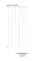
Appendix J, ASCII Table
Decimal
0
1
2
3
4
5
6
7
8
9
10
11
12
13
14
15
16
17
18
19
20
21
22
23
24
25
26
27
28
29
30
31
32
33
34
35
36
37
38
39
40
41
42
43
44
45
46
47
48
49
50
51
52
53
54
55
56
57
58
59
60
61
62
63
Hex
0
1
2
3
4
5
6
7
8
9
A
B
C
D
E
F
10
11
12
13
14
15
16
17
18
19
1A
1B
1C
1D
1E
1F
20
21
22
23
24
25
26
27
28
29
2A
2B
2C
2D
2E
2F
30
31
32
33
34
35
36
37
38
39
3A
3B
3C
3D
3E
3F
ASCII
xx
xx
xx
xx
xx
xx
xx
xx
xx
xx
xx
xx
xx
xx
xx
xx
xx
xx
xx
xx
xx
xx
xx
xx
xx
xx
xx
xx
xx
xx
xx
xx
!
"
#
$
%
&
'
(
)
*
+
,
.
/
0
1
2
3
4
5
6
7
8
9
:
;
<
=
>
?
Decimal
64
65
66
67
68
69
70
71
72
73
74
75
76
77
78
79
80
81
82
83
84
85
86
87
88
89
90
91
92
93
94
95
96
97
98
99
100
101
102
103
104
105
106
107
108
109
110
111
112
113
114
115
116
117
118
119
120
121
122
123
124
125
126
127
Hex
ASCII
40
41
42
43
44
45
46
47
48
49
4A
4B
4C
4D
4E
4F
50
51
52
53
54
55
56
57
58
59
5A
5B
5C
5D
5E
5F
60
61
62
63
64
65
66
67
68
69
6A
6B
6C
6D
6E
6F
70
71
72
73
74
75
76
77
78
79
7A
7B
7C
7D
7E
7F
@
A
B
C
D
E
F
G
H
I
J
K
L
M
N
O
P
Q
R
S
T
U
V
W
X
Y
Z
[
\
]
^
_
`
a
b
c
d
e
f
g
h
i
j
k
l
m
n
o
p
q
r
s
t
u
v
w
x
y
z
{
|
}
~
xx
NOTE: xx indicates non printable character
CT600.1-3 and CT300.1-3
BKC-DIP Product Specific Appendices
Version 2.00.06
Updated 08/27/09
Page 37 of 59
Appendix K, LED Mapping
LED
01h
02h
04h
08h
10h
20h
40h
80h
Buffer 0
= UP
= ZONE
= MENU
= SOURCE
= PRESET
= SLEEP
= ENTER
= SAVE
LED
01h
02h
04h
08h
10h
20h
40h
80h
Buffer
= DOWN
= <NOT
= <NOT
= <NOT
= <NOT
= <NOT
= <NOT
= <NOT
1
USED>
USED>
USED>
USED>
USED>
USED>
USED>
NOTE: Due to the front panel electronics, all LEDs are in the same electrical bank. Only one of
the LEDs should be active at a time.
NOTE: Due to the lack of front panel electronics, LEDs commands do not apply to a
CT600.1-3/300.1-3.
CT600.1-3 and CT300.1-3
BKC-DIP Product Specific Appendices
Version 2.00.06
Updated 08/27/09
Page 38 of 59
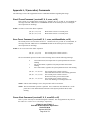
Appendix L, X (executive) Commands
The following is a list of the supported Executive commands and details regarding their usage:
Recall Preset Command: (receiveID, X, 0, z=nn; cs16)
Zone z Preset nn is recalled to the current preset. Similar to the "G" get and “S” set commands, nn
can range from 00h – FDh, however it CANNOT be FFh for the current preset (as recalling the
current preset has no meaning).
NOTE: nn of FE is reserved for future expansion.
(00, X, 0, 1=4;cs16)
(00, X, 0, 2=7;cs16)
Recall Zone 1 Preset 4 to current preset
Recall Zone 2 Preset 7 to current preset
Save Preset Command: (receiveID, X, 1, z=nn, autoNameMode; cs16)
The current preset is saved to Zone z Preset nn. . Similar to the "G" get and “S” set commands, nn
can range from 00h – FDh, however it CANNOT be FFh for the current preset (as saving the
current preset has no meaning).
NOTE: nn of FE is reserved for future expansion.
(00, X, 1, 1=3;cs16)
(00, X, 1, 2=9;cs16)
Save current preset to Zone 1 Preset 3
Save current preset to Zone 2 Preset 9
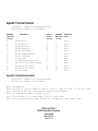
The autoNameMode specifier can take on the following values with the following meanings:
0
1
2
Auto Name Preset, based upon state of System parameter Preset Auto
Naming
Do not Auto Name, regardless of System parameter Preset Auto
Naming
Force Auto Name, regardless of System parameter Preset Auto Naming
(00, X, 1, 1=8, 0;cs16)
(00, X, 1, 1=8, 1;cs16)
(00, X, 1, 1=8, 2;cs16)
Save current preset to Zone 1 Preset 8
Auto Name based on Preset Auto Naming parameter
Save current preset to Zone 1 Preset 8
Do not Auto Name, preserve Preset Title
Save current preset to Zone 1 Preset 8
Force Auto Naming, overwriting Preset Title
NOTE: If Preset Auto Naming is active, the preset title will be overwritten.
NOTE: The autoNameMode specifier is optional. If it is omitted its value defaults to 0, so the
preset title is Auto Named based on the state of the System parameter Preset Auto
Naming.
Power State Command: (receiveID, X, 2, z=onOff; cs16)
Zone z’s power state may be controlled using this command. The onOff parameter may take on
the values of 1 or 0 for “on” or “off (Sleep)” respectively.
CT600.1-3 and CT300.1-3
BKC-DIP Product Specific Appendices
Version 2.00.06
Updated 08/27/09
Page 39 of 59
(00, X, 2, 1=1;cs16)
(00, X, 2, 2=0;cs16)
Turn Z1 power on (unit not in Sleep)
Turn Z2 power off (unit in Sleep)
NOTE: A Power State Command “on” is referred to as a “Warm Boot”.
Cold Boot Command: (receiveID, X, 6; cs16)
This forces the unit to do a “Cold Boot”, which is the same sequence of events that occur when the
unit is turned on from the power on/off switch. This differs from a “Warm Boot” (Power State
Command with On/Off state of 1) in that all of the unit’s hardware is re-initialized.
NOTE: After issuing a Cold Boot command, the unit’s communication port is reinitialized.
Communication will have to be re-established. The unit cannot receive BKC-DIP
commands until the Update Unit “BKC-DIP ACTIVE” reply has been transmitted by the
unit (see Update Command below for further details).
Factory Reset Command: (receiveID, X, 7; cs16)
This command executes the factory-reset sequence in the unit. The factory reset returns the state
of the unit to its original factory settings.
WARNING!:
Issuing a Factory Reset Command will destroy all user modified data in the
unit (preset, system settings, etc.).
NOTE: After issuing a Factory Reset command, the unit’s communication port is reinitialized.
Communication will have to be re-established. The unit cannot receive BKC-DIP
commands until the Update Unit “BKC-DIP ACTIVE” reply has been transmitted by the
unit (refer to the Update Command in the BKC-DIP Specification for further details).
Reinitialize BKC-DIP State Command: (receiveID, X, 8; cs16)
There are certain parameters and settings that are only available via BKC-DIP. On cold boot,
these states are reset. It may be desirable to reset these states without performing a cold boot. The
Reinitialize BKC-DIP State does the following:
1.
2.
3.
4.
Exits Override mode (setting Active to False), resets the acknowledge timeout to 0,
and resets all other override parameters to their corresponding System Settings (i.e.
the Override Baud Rate is reset to the System Baud Rate)
Disables all Realtime events
Restores Audio/Video linked on all zones
Resets all RS232 control out states for all inputs to off
NOTE: This command does not reset the state of the BKC-DIP parser.
Mute State Command: (receiveID, X, A, z=muteState; cs16)
This command is used to mute/unmute particular zones where z is the zone number and muteState
is 0 or 1 (unmuted or muted).
(0, X, A, 1=1; cs16)
(0, X, A, 1=0; cs16)
(0, X, A, 2=1; cs16)
(0, X, A, 2=0; cs16)
Mute Zone 1
Unmute Zone 1
Mute Zone 2
Unmute Zone 2
CT600.1-3 and CT300.1-3
BKC-DIP Product Specific Appendices
Version 2.00.06
Updated 08/27/09
Page 40 of 59
NOTE: This mute is the same as muting from an IR command. It also follows the same logic,
specifically that a Volume Up message on a specific zone will unmute that zone.
Initiate Flashloader Command: (receiveID, X, B; cs16)
This command initiates a flashloader mode to allow flash B&K firmware updates via TFTP. The
“initiate flashloader command” will disconnect all active telnet connections and will start the
B&K flashloader application. Once the unit is in the flashloader mode, the unit will start a new
telnet connection after the DHCP is assigned. After the telnet connection is reestablished, TFTP
Flash Load can be started with “TFTP Client Load Command: (receiveID, X, D; cs16)”.
This executive command is used only on bootloader, and only valid when transmitted via an
Ethernet connection.
Clear Flash Block Command: (receiveID, X, C=xx; cs16)
This command initiates an erase of flash memory starting at the specified flash block.
Example (FF,X, C=41;) Clears the 64k flash block starting at 0x410000.
This executive command is used only on bootloader, and only valid when transmitted via an
Ethernet connection.
TFTP Client Load Command: (receiveID, X, D; cs16)
This command initiates a TFTP client with the server name and information set under Unit Info
Parameters 51 and 52 (see Appendix E Unit Parameters). The TFTP client load will load a new
“Flash Upgrade” file.
Status responds with a error log (see Appendix M, Error Logs) parameter 0A = 0 or 1. 0 = bad and
1 = good.
This executive command is used only on bootloader, and only valid when transmitted via an
Ethernet connection.
WARNING!:
Issuing a TFTP Client Load Command will destroy all user modified data in
the unit (preset, system settings, etc.).
Unsupported Executive Commands
The following Executive Commands are not supported by the CT600.1-3/300.1-3:
Noise Generator State Command: (receiveID, X, 3, noiseState; cs16)
Noise Steering Command: (receiveID, X, 4, speakerIndex=onOff, ... speakerIndex=onOff; cs16)
Noise Increment Command: (receiveID, X, 5; cs16)
Test Tone State Command: (receiveID, X, 9, level; cs16)
CT600.1-3 and CT300.1-3
BKC-DIP Product Specific Appendices
Version 2.00.06
Updated 08/27/09
Page 41 of 59
Appendix M, Error Logs
(0,G,E,0;cs16)
(0,S,E,0=0;cs16)
Identifier
(in hex)
00
01
02
03
04
05
06
07
08
09
0A
0B
Example of Get Primary Preset Errors
Example of Set Primary Preset Errors
Description
Note
Primary Preset Error Log
Secondary Preset Error Log
Primary System Error Log
Secondary System Error Log
Primary Preserved Error Log
Secondary Preserved Error Log
Serial Number Error Log
Signature Error Log
Non Volatile Write Error Log
Block Memory Erase Error Log
Flash Memory Load Error Log
Undefined Command Error Log
Note
Note
Note
Note
Note
Note
Note
Note
Note
Note
Note
Note
1
1
2
2
3
3
4
5
6
7
8
9
Appendix M, Error Logs Parameter Notes
General Note 1: If error is detected in the primary preset memory, the
error is logged as a primary error, then the settings are
recovered from the secondary (backup) settings. If the
secondary settings are corrupted, the error is logged as a
secondary error, and the settings are forced to their default
value.
General Note 2: Error Logs are not reset by factory reset. To clear
error logs, the value of 0 must explicitly be written to each
identifier via a BKC-DIP set (S), command.
Note 1:
Note 2:
Note 3:
Note 4:
Note 5:
Note 6:
Note 7:
Note 8:
Indicates data corruption in Preset primary/secondary
settings.
Indicates data corruption in System primary/secondary
settings.
Indicates data corruption in Preserved primary/secondary
settings.
Indicates data corruption of one of the redundant serial
number entries.
Indicates data corruption of one of the redundant signature
entries.
Indicates general low level write error to non-volatile memory
device.
Indicates data corruption during flash block erase command.
Example (FF,R,E,09=0;) Block successfully erased.
Example (FF,R,E,09=41;) Error erasing flash block 41.
This executive command is used only on bootloader
Indicates data corruption during the flash block load command.
Example (FF,R,E,0A=00;) Flash memory successfully loaded.
Example (FF,R,E,0A=42;) Error loading flash block 42.
This executive command is used only on bootloader
CT600.1-3 and CT300.1-3
BKC-DIP Product Specific Appendices
Version 2.00.06
Updated 08/27/09
Page 42 of 59
Note 9:
Indicates an undefined command sent during flash memory load.
Example (FF,R,E,0B=01;) Error undefined command.
This executive command is used only on bootloader
CT600.1-3 and CT300.1-3
BKC-DIP Product Specific Appendices
Version 2.00.06
Updated 08/27/09
Page 43 of 59
Appendix N, Zone Specific Parameters
(0,G,Z1,0;cs16)
Example of Get Zone 1 Title
(0,S,Z9,2=3;cs16) Example of Set Zone 9 Audio Input Power On
Preference to In 1
Parameter
Identifier
(in hex)
00
01
02
03
04
05
06
07
08
09
0A
0B
0C
0D
0E
0F
10
11
12
13
14
15
16
17
18
19
1A
1B
1C
1D
1E
1F
20
21
22
23
24
25
Description
Parameter
Max Values
(in hex)
Title
“B”
Audio Input Power On Setting
1
Audio Input Power On Preference
B
Video Input Power On Setting
1
Video Input Power On Preference
9
Volume Power On Setting
1
Volume Power On Preference
28
Bass Power On Setting
1
Bass Power On Preference
C
Treble Power On Setting
1
Treble Power On Preference
C
Equalization Power On Setting
1
Equalization Power On Preference
2
AM Frequency Power On Setting
1
AM Frequency Power On Preference
74,81
FM Frequency Power On Setting
1
FM Frequency Power On Preference
67,CD
FM Stereo Mode Power On Setting
1
FM Stereo Mode Power On Preference 1
Zone List
“2F”
Favorite Presets 0-7 Indicators
FF
Favorite Presets 8-15 Indicators
FF
Favorite Presets 16-23 Indicators
FF
Favorite Presets 24-31 Indicators
FF
Favorite Presets 32-39 Indicators
FF
Favorite Presets 40-47 Indicators
FF
Favorite Presets 48-55 Indicators
FF
Favorite Presets 56-63 Indicators
FF
Favorite Presets 64-71 Indicators
FF
Favorite Presets 72-79 Indicators
FF
Favorite Presets 80-87 Indicators
FF
Favorite Presets 88-95 Indicators
FF
Favorite Presets 96-99 Indicators
0F
Absolute/Relative Setting
1
Left (Stereo) Hardware Group Mask
3F
Right Hardware Group Mask
3F
Zone Power State
1
Zone Mute State
1
CT600.1-3 and CT300.1-3
BKC-DIP Product Specific Appendices
Version 2.00.06
Updated 08/27/09
Page 44 of 59
Formatting
Notes
Note
Note
Note
Note
Note
Note
Note
Note
Note
Note
Note
Note
Note
Note
Note
Note
Note
Note
Note
Note
Note
Note
Note
Note
Note
Note
Note
Note
Note
Note
Note
Note
Note
Note
Note
Note
Note
1
2
1
12
1
3
1
4
1
4
1
5
1
6,6a
1
7,7a
1
8
10
9
9
9
9
9
9
9
9
9
9
9
9
9
11
13
13
15
16
Appendix N, Zone Specific Parameter Notes
Note
Note
Note
Note
Note
Note
Note
Note
Note
Note
Note
(0,G,Z1,0;cs16)
Example of Get Zone 1 Title
(0,S,Z9,2=3;cs16) Example of Set Zone 9 Audio Input Power On
Preference to In 1
1: 0h = Last Used
1h = Preferred Value
2: 0h = FM Tuner
1h = AM Tuner
2h = Dedicated Zone In
3h = In1
4h = In2
5h = In3
6h = In4
7h = In5
8h = In6
9h = In7
Ah = In8
Bh = In9
3: 0h = -80 dB, 1h = -78 dB ... 28h = +0 dB
4: 0h = -12.0 dB, 1h = -10 dB, ... 6h = 0.0 dB, ... Ch = +12.0 dB
5: 0h = Off, 1h = Loudness, 2h = Auto Level
6: 10 kHz AM step tuning (USA)
(((value – 1) * 10) + 520) kHz, or
(((AM_kHz - 520) / 10) + 1) with
2Ah = 930 KHz; 00h indicates an uninitialized frequency.
If tuner stations programmed, last used station's frequency
is used, else 520 kHz.
6a: 9 kHz AM step tuning
(((value – 1)* 9) + 522) kHz, or
(((AM_kHz - 522) / 9) + 1) with
2Eh = 927 KHz; 00h indicates an uninitialized station.
If tuner stations programmed, last used station's frequency
is used, else 522 kHz.
7: 200 kHz FM step tuning (USA)
(((value – 1)* 0.20 ) + 87.5) MHz, or
(((FM_MHz - 87.5) /0.2) + 1) with
4Ch = 102.5 MHz; 00h indicates an uninitialized frequency.
If tuner stations programmed, last used station's frequency
is used, else 87.5 MHz.
7a: 100 kHz FM step tuning
(((value – 1)* 0.10 ) + 87.5) MHz, or
(((FM_MHz - 87.5) /0.1) + 1) with 97h = 102.5 MHz; 00h
indicates an uninitialized frequency. If tuner stations
programmed, last used station's frequency
is used, else 87.5 MHz.
8: 0h = Mono
1h = Stereo
9: The Favorite Preset Indicators are bitmaps. Each register
represents 8 presets. The lowest preset number of the 8
presets corresponds to the least significant bit (right-most
bit, bit 0), while the highest preset number of the 8
corresponds to the most significant bit (left-most bit, bit
7). If a bit is set (i.e. a “1” in that position) the
corresponding preset is a Favorite for that Logical Zone.
CT600.1-3 and CT300.1-3
BKC-DIP Product Specific Appendices
Version 2.00.06
Updated 08/27/09
Page 45 of 59
For example, given the following Favorite Preset Indicator
settings:
Identifier
14
15
16
17
18
19
1A
1B
1C
1D
1E
1F
Value
01h
80h
87h
C0h
E0h
F0h
03h
07h
0Fh
00h
11h
FFh
20
0Fh
Comment
Preset 0 is Favorite
Preset 15 is Favorite
Preset 16, 17, 18, and 23 Favorite
Preset 30 and 31 Favorite
Preset 37, 38, and 39 Favorite
Preset 44, 45, 46, and 47 Favorite
Preset 48 and 49 Favorite
Preset 56, 57, and 58 Favorite
Preset 64, 65, 66, and 67 Favorite
No Favorites in Presets 72-79
Presets 80 and 84 Favorite
Preset 88, 89, 90, 91, 92, 93, 94,
and 95 Favorite
Preset 96, 97, 98 and 99 Favorite
Specifically looking at the Preset 16-23 Favorite Indicator
(identifier 15h) as an example given its value of 87h:
Bit
Value
Comment
0
1
Preset 16 is Favorite
1
1
Preset 17 is Favorite
2
1
Preset 18 is Favorite
3
0
Preset 19 is not Favorite
4
0
Preset 20 is not Favorite
5
0
Preset 21 is not Favorite
6
0
Preset 22 is not Favorite
7
1
Preset 23 is Favorite
Note 10: The Zone List is a string indicating the Zone Hardware (Zones
A, B, C, D, E or F) associated with the particular Logical
Zone. The format of the string is Zone Hardware specifiers
delimited by whitespace. Each Zone Hardware specifier has the
format:
ZoneLetter.channelSpecifier
Where ZoneLetter can be A, B, C, D, E, or F, seperated by a
period (referred to a “dot”), and the ChannelSpecifier can be
L or R (signifying the Left or Right hardware channel).
An example of a Zone List is:
“A.L A.R C.L D.R F.L F.R”
In this example, this particular logical zone encompasses Zone
A Left and Right, Zone C Left, Zone D Right, and Zone F Left
and Right.
Note 11: 0h = relative, 1h = absolute
CT600.1-3 and CT300.1-3
BKC-DIP Product Specific Appendices
Version 2.00.06
Updated 08/27/09
Page 46 of 59
Note 12: 0h = Dedicated
1h = In1
2h = In2
3h = In3
4h = In4
5h = In5
6h = In6
7h = In7
8h = In8
9h = In9
Note 13: Bitmaps indicating which hardware zone outputs are associated
with the Group which has this Zone (code set). If the bit is
set (i.e. 1) that particular hardware zone output is valid.
Bit
0
1
2
3
4
5
6
7
Output Represented
Zone A
Zone B
Zone C
Zone D
Zone E
Zone F
unused
unused
NOTE: If hardware zone is configured in Stereo Mode, the
appropriate bits of the Right Group Mask are ignored, and the
Left Group Mask bits determine the grouping for both the Left
and Right sides of the hardware zone.
Note 14:
Bitmaps indicating which hardware zone outputs are associated
with the Group which has this Zone (code set). If the bit is
set (i.e. 1) that particular hardware zone output is valid.
Note 15: 0h = power off, 1h = power on
Note 16: 0h = volume mute off, 1h = volume mute on
CT600.1-3 and CT300.1-3
BKC-DIP Product Specific Appendices
Version 2.00.06
Updated 08/27/09
Page 47 of 59
Appendix O, Macro Parameters
(0,G,M0=16,5;cs16)
(0,S,M0=1,5=”Hello”;cs16)
Example of Get Serial Macro 16 Message
Example of Set Serial Macro 1 Message
Supported Macro Types
Type
0
Description
Serial Macro Type
Serial Macro Parameters
Parameter
Identifier
(in hex)
00
01
02
03
04
05
06
07
08
09
0A
0B
0C
0D
Description
Serial
Serial
Serial
Serial
Serial
Serial
Serial
Serial
Serial
Serial
Serial
Serial
Serial
Serial
Macro
Macro
Macro
Macro
Macro
Macro
Macro
Macro
Macro
Macro
Macro
Macro
Macro
Macro
Trigger ID
Trigger Code
Scrollable
Baud Rate
Output Mask
Message
Message Size MSB
Message Size LSB
Free Space MSB
Free Space LSB
Send Type
Logic
Event Trigger
IP Address
Parameter
Max Values
(in hex)
80
FF
1
8
3F
2000
20
FF
20
FF
2
1
5D
“16”
Formatting
Notes
Note
Note
Note
Note
Note
Note
Note
Note
Note
Note
Note
Note
Note
Note
1
2
3
4
5
6
7
7
8
8
9
10
11
12
General Notes Regarding Serial Macros
All the parameters of a serial macro are stored with that particular macro. If every identifier is not
specified, default settings are used. The following documents the default settings used for the particular
identifiers:
Parameter
(in hex)
00
01
02
03
04
05
Description
Default Value
Serial Macro Trigger ID
0
Serial Macro Trigger Code
0
Serial Macro Scrollable
0
Serial Macro Baud Rate
*
*Same as System Parameter AAh, the System RS-232 Baud Rate
Serial Macro Output Mask
3F
Serial Macro Message
“EMPTY”
CT600.1-3 and CT300.1-3
BKC-DIP Product Specific Appendices
Version 2.00.06
Updated 08/27/09
Page 48 of 59
Serial Macro Parameter Notes
(0,G,M0=10,5;cs16)
(0,S,M0=1,5=”Hello”;cs16)
Note 1:
Note 2:
Note 3:
Note 4:
Note 5:
Example of Get Serial Macro 16 Message
Example of Set Serial Macro 1 Message
0h = Zone ID of 0, 1h = Zone ID of 1, … 80h = Zone ID of 128
0h = IR Code 0, 1h = IR Code 1, … FFh = IR Code 255
0h = No
1h = Yes
Scrollable indicates that a Serial Macro Messages will be
transmitted every time an IR code Trigger Code is received.
Non-scrollable indicates that a single Serial Macro Message
will be transmitted when an IR code Trigger Code is received,
but subsequent messages will not be transmitted until the user
releases the IR remote and presses it again.
0h = 1200
1h = 2400
2h = 9600
3h = 14400
4h = 19200
5h = 28800
6h = 38400
7h = 57600
8h = 115200
Bitmap indicating which Hardware Zones (Zones A, B, C, D, E or
F) to allow RS-232 data to be output. If the bit is set, the
data will be output.
Zone
Zone
Zone
Zone
Zone
Zone
A
B
C
D
E
F
01h
02h
04h
08h
10h
20h
Thus an output mask of 2Bh would allow serial macros to be
output on Zone A, Zone B, Zone D and Zone F, but NOT on Zone C
and Zone E.
NOTE:
The serial macro is always transmitted out the
“primary” serial port connection, i.e. the RJ45
connector. An output mask of 00h will mask all data to
the Hardware Zone outputs, but the macro will still be
transmitted to the primary serial port.
CT600.1-3 and CT300.1-3
BKC-DIP Product Specific Appendices
Version 2.00.06
Updated 08/27/09
Page 49 of 59
Note 6:
There is 2000h, 8192 decimal, bytes allocated in non-volatile
memory for use by the serial macros. Each macro consumes:
1
2
1
1
1
1
byte
bytes
byte
byte
byte
byte
+
x bytes
Macro
Macro
Macro
Macro
Macro
Macro
Number
Length
Trigger ID
Trigger Code
Scrollable and BaudRate
Output Mask
Macro Message Length
As an example, a macro message of “Hello World” would consume
7 + 11 bytes of memory.
Thus the amount of memory available for a macro is variable,
depending upon what other macros currently exist. In the one
extreme case of the largest single message, one could create a
single macro with a message length of 8185 characters.
NOTE:
Although the Serial Macro structures can accommodate
very large string lengths, the practical limit for macro
message length is approximately 2000 bytes. This is due
to the fact that the receive buffer in the unit is only
2048 (2k) bytes long, and processing of the message
cannot occur until the entire message is received. Thus
it is not possible to send a valid BKC-DIP message to a
CT600.1-3/300.1-3 of length longer than 2048 bytes.
Taking into account the syntax overhead of BKC-DIP
(receive ID, checksum, open/close parenthesis, etc.)
leaves approximately 2000 bytes for an actual Serial
Macro message. Should this become an issue, create 2
independent macros with the same trigger IDs and trigger
codes. The macro number will determine the priority of
the macros with matching trigger conditions, with lower
macro numbers having the higher priority.
In the other extreme case of maximum number of macros (255,
macro numbers 0h through FEh), each macro would have a message
length of 25 characters.
NOTE:
If a macro is too large for the available space, it is
not accepted. Monitoring the maximum free space is
recommended by reading the Macro Free Space MSB and LSB
(see Note 8 below) to indicate how much available macro
space is available before attempting to write a macro
message.
Special Escape Character \:
Time \\Txy (xy is in hexadecimal with 0.1 second
increment)
ie.
\\TFF is 25.5 seconds delay
\\T01 is 0.1 seconds delay
\\T02 is 0.2 seconds delay
\\T03 is 0.3 seconds delay
CT600.1-3 and CT300.1-3
BKC-DIP Product Specific Appendices
Version 2.00.06
Updated 08/27/09
Page 50 of 59
Note 7:
Hexadecimal data interpretation \\xy (xy is
transmitted as a single Hex data byte instead of two
ASCII bytes).
BKC-DIP String message \" allows quotes to be used for
building BKC-DIP strings messages. Note: every \QUOTE
requires a closing \QUOTE for the BKC-DIP string parser
to know when to end string message.
i.e. \”HELLO WORLD\”
READ ONLY PARAMETER indicating size of the specified serial
macro. Since the macro’s size can be greater than 255 bytes,
2 bytes are required to represent the size, MSB (most
significant byte) and LSB (least significant byte). To form
the size, perform the following calculation:
Size = (MSB Value * 256) + LSB Value
As an example, assume the MSB and LSB return values were 10h
and F3h respectively.
Size = (10h * 256) + F3h
Size = (16 * 256) + 243 = 4339 bytes
The other way to form the complete size is to concatenate the
MSB and the LSB hexadecimal characters. Using the above
example:
Note 8:
Size = 10F3h
READ ONLY PARAMETER
serial macro area.
area can be greater
represent the size,
significant byte).
calculation:
= 4339 bytes
indicating remaining free space in the
Since the free space in the serial macro
than 255 bytes, 2 bytes are required to
MSB (most significant byte) and LSB (least
To form the size, perform the following
Size = (MSB Value * 256) + LSB Value
Or by concatenating the MSB and LSB hexadecimal characters
together. See Note 6 above for examples.
Note 9:
0h = RS-232, 1h = Internal, 2h = UDP,
3h = TCP (TCP currently not supported)
Note 10: 0h = AND, 1h = OR
Note 11: 00
01
02
03
04
05
06
07
08
09
0A
=
=
=
=
=
=
=
=
=
=
=
NONE
SYSTEM
SYSTEM
ZONE A
ZONE A
ZONE B
ZONE B
ZONE C
ZONE C
ZONE D
ZONE D
ON
OFF
ON
OFF
ON
OFF
ON
OFF
ON
OFF
CT600.1-3 and CT300.1-3
BKC-DIP Product Specific Appendices
Version 2.00.06
Updated 08/27/09
Page 51 of 59
0B
0C
0D
0E
0F
10
11
12
13
14
15
16
17
18
19
1A
1B
1C
1D
1E
1F
20
21
22
23
24
25
26
27
28
29
2A
2B
2C
2D
2E
2F
30
31
32
33
34
35
36
37
38
39
3A
3B
3C
3D
3E
3F
40
41
=
=
=
=
=
=
=
=
=
=
=
=
=
=
=
=
=
=
=
=
=
=
=
=
=
=
=
=
=
=
=
=
=
=
=
=
=
=
=
=
=
=
=
=
=
=
=
=
=
=
=
=
=
=
=
ZONE E ON
ZONE E OFF
ZONE F ON
ZONE F OFF
CONTROL IN 1 ON
CONTROL IN 1 OFF
CONTROL IN 2 ON
CONTROL IN 2 OFF
PAGE EVENT 1 ON
PAGE EVENT 1 OFF
PAGE EVENT 2 ON
PAGE EVENT 2 OFF
DEDICATED IN A ON
DEDICATED IN A OFF
DEDICATED IN B ON
DEDICATED IN B OFF
DEDICATED IN C ON
DEDICATED IN C OFF
DEDICATED IN D ON
DEDICATED IN D OFF
DEDICATED IN E ON
DEDICATED IN E OFF
DEDICATED IN F ON
DEDICATED IN F OFF
INPUT 1 AUDIO SENSE
INPUT 1 VIDEO SENSE
INPUT 1 A V SENSE
INPUT 2 AUDIO SENSE
INPUT 2 VIDEO SENSE
INPUT 2 A V SENSE
INPUT 3 AUDIO SENSE
INPUT 3 VIDEO SENSE
INPUT 3 A V SENSE
INPUT 4 AUDIO SENSE
INPUT 4 VIDEO SENSE
INPUT 4 A V SENSE
INPUT 5 AUDIO SENSE
INPUT 5 VIDEO SENSE
INPUT 5 A V SENSE
INPUT 6 AUDIO SENSE
INPUT 6 VIDEO SENSE
INPUT 6 A V SENSE
INPUT 7 AUDIO SENSE
INPUT 7 VIDEO SENSE
INPUT 7 A V SENSE
INPUT 8 AUDIO SENSE
INPUT 8 VIDEO SENSE
INPUT 8 A V SENSE
INPUT 9 AUDIO SENSE
INPUT 9 VIDEO SENSE
INPUT 9 A V SENSE
INPUT A AUDIO SENSE
INPUT A VIDEO SENSE
INPUT A A V SENSE
INPUT B AUDIO SENSE
CT600.1-3 and CT300.1-3
BKC-DIP Product Specific Appendices
Version 2.00.06
Updated 08/27/09
Page 52 of 59
42
43
44
45
46
47
48
49
4A
4B
4C
4D
4E
4F
50
51
52
53
54
55
56
57
58
59
5A
5B
5C
5D
01
02
03
04
05
06
07
08
09
0A
0B
0C
0D
0E
0F
10
11
12
13
14
15
16
17
18
19
1A
1B
=
=
=
=
=
=
=
=
=
=
=
=
=
=
=
=
=
=
=
=
=
=
=
=
=
=
=
=
=
=
=
=
=
=
=
=
=
=
=
=
=
=
=
=
=
=
=
=
=
=
=
=
=
=
=
INPUT B VIDEO SENSE
INPUT B A V SENSE
INPUT C AUDIO SENSE
INPUT C VIDEO SENSE
INPUT C A V SENSE
INPUT D AUDIO SENSE
INPUT D VIDEO SENSE
INPUT D A V SENSE
INPUT E AUDIO SENSE
INPUT E VIDEO SENSE
INPUT E A V SENSE
INPUT F AUDIO SENSE
INPUT F VIDEO SENSE
INPUT F A V SENSE
SYSTEM CONTROL IN 1
SYSTEM CONTROL IN 2
ZONE A CONTROL IN 1
ZONE A CONTROL IN 2
ZONE B CONTROL IN 1
ZONE B CONTROL IN 2
ZONE C CONTROL IN 1
ZONE C CONTROL IN 2
ZONE D CONTROL IN 1
ZONE D CONTROL IN 2
ZONE E CONTROL IN 1
ZONE E CONTROL IN 2
ZONE F CONTROL IN 1
ZONE F CONTROL IN 2
SYSTEM ON
SYSTEM OFF
ZONE A ON
ZONE A OFF
ZONE B ON
ZONE B OFF
ZONE C ON
ZONE C OFF
ZONE D ON
ZONE D OFF
ZONE E ON
ZONE E OFF
ZONE F ON
ZONE F OFF
CONTROL IN 1 ON
CONTROL IN 1 OFF
CONTROL IN 2 ON
CONTROL IN 2 OFF
PAGE EVENT 1 ON
PAGE EVENT 1 OFF
PAGE EVENT 2 ON
PAGE EVENT 2 OFF
DEDICATED IN A ON
DEDICATED IN A OFF
DEDICATED IN B ON
DEDICATED IN B OFF
DEDICATED IN C ON
SENSE
SENSE
SENSE
SENSE
SENSE
SENSE
SENSE
SENSE
SENSE
SENSE
SENSE
SENSE
SENSE
SENSE00 = NONE
CT600.1-3 and CT300.1-3
BKC-DIP Product Specific Appendices
Version 2.00.06
Updated 08/27/09
Page 53 of 59
1C
1D
1E
1F
20
21
22
23
24
25
26
27
28
29
2A
2B
2C
2D
2E
2F
30
31
32
33
34
35
36
37
38
39
3A
3B
3C
3D
3E
3F
40
41
42
43
44
45
46
47
48
49
4A
4B
4C
4D
4E
4F
50
51
52
=
=
=
=
=
=
=
=
=
=
=
=
=
=
=
=
=
=
=
=
=
=
=
=
=
=
=
=
=
=
=
=
=
=
=
=
=
=
=
=
=
=
=
=
=
=
=
=
=
=
=
=
=
=
=
DEDICATED IN C OFF
DEDICATED IN D ON
DEDICATED IN D OFF
DEDICATED IN E ON
DEDICATED IN E OFF
DEDICATED IN F ON
DEDICATED IN F OFF
INPUT 1 AUDIO SENSE
INPUT 1 VIDEO SENSE
INPUT 1 A V SENSE
INPUT 2 AUDIO SENSE
INPUT 2 VIDEO SENSE
INPUT 2 A V SENSE
INPUT 3 AUDIO SENSE
INPUT 3 VIDEO SENSE
INPUT 3 A V SENSE
INPUT 4 AUDIO SENSE
INPUT 4 VIDEO SENSE
INPUT 4 A V SENSE
INPUT 5 AUDIO SENSE
INPUT 5 VIDEO SENSE
INPUT 5 A V SENSE
INPUT 6 AUDIO SENSE
INPUT 6 VIDEO SENSE
INPUT 6 A V SENSE
INPUT 7 AUDIO SENSE
INPUT 7 VIDEO SENSE
INPUT 7 A V SENSE
INPUT 8 AUDIO SENSE
INPUT 8 VIDEO SENSE
INPUT 8 A V SENSE
INPUT 9 AUDIO SENSE
INPUT 9 VIDEO SENSE
INPUT 9 A V SENSE
INPUT A AUDIO SENSE
INPUT A VIDEO SENSE
INPUT A A V SENSE
INPUT B AUDIO SENSE
INPUT B VIDEO SENSE
INPUT B A V SENSE
INPUT C AUDIO SENSE
INPUT C VIDEO SENSE
INPUT C A V SENSE
INPUT D AUDIO SENSE
INPUT D VIDEO SENSE
INPUT D A V SENSE
INPUT E AUDIO SENSE
INPUT E VIDEO SENSE
INPUT E A V SENSE
INPUT F AUDIO SENSE
INPUT F VIDEO SENSE
INPUT F A V SENSE
SYSTEM CONTROL IN 1 SENSE
SYSTEM CONTROL IN 2 SENSE
ZONE A CONTROL IN 1 SENSE
CT600.1-3 and CT300.1-3
BKC-DIP Product Specific Appendices
Version 2.00.06
Updated 08/27/09
Page 54 of 59
53
54
55
56
57
58
59
5A
5B
5C
5D
=
=
=
=
=
=
=
=
=
=
=
ZONE
ZONE
ZONE
ZONE
ZONE
ZONE
ZONE
ZONE
ZONE
ZONE
ZONE
A
B
B
C
C
D
D
E
E
F
F
CONTROL
CONTROL
CONTROL
CONTROL
CONTROL
CONTROL
CONTROL
CONTROL
CONTROL
CONTROL
CONTROL
IN
IN
IN
IN
IN
IN
IN
IN
IN
IN
IN
2
1
2
1
2
1
2
1
2
1
2
SENSE
SENSE
SENSE
SENSE
SENSE
SENSE
SENSE
SENSE
SENSE
SENSE
SENSE
Note 12: Standard IP format in String. i.e. “255.255.255.255:65535”
CT600.1-3 and CT300.1-3
BKC-DIP Product Specific Appendices
Version 2.00.06
Updated 08/27/09
Page 55 of 59
Appendix P, Override Parameters
(0,G,O,0;cs16)
(0,S,O,4=1;cs16)
Parameter
Identifier
(in hex)
00
01
02
03
04
05
08
09
0A
0B
0C
0D
FF
Example of Get Override Active state
Example of Set Echo Enabled
Description
Override Active
RS-232 Baud Rate
BKC-DIP Receive ID
BKC-DIP Transmit ID
BKC-DIP Echo Enabled
BKC-DIP Feedback Selection
RS-232 V2.0 Enabled
OSD Reply Mode
Front Panel Display Reply Mode
Auto BKC-DIP Set IR Generate Enable
Auto BKC-DIP Set IR Mask
Auto BKC-DIP Set IR TX ID
Override Timeout
Default
Values
(in hex)
0
2
00
00
0
0
0
0
0
1
3F
80
0
Parameter
Max Values
(in hex)
1
8
7F
7F
1
3
1
2
2
1
3F
80
FF
Formatting
Notes
Note
Note
Note
Note
Note
Note
Note
Note
Note
Note
Note
Note
Note
1
2
3
3
1
4
1
7
7
4
8
6
5
Appendix P, Override Parameters Notes
(0,G,O,0;cs16)
(0,S,O,4=1;cs16)
Note
Note
Note
Note
Note
Note
1:
2:
3:
4:
5:
6:
Example of Get Override Active state
Example of Set Echo Enabled
Not Applicable.
0h = 1200, 1h = 2400, 2h = 9600, 3h = 14400, 4h = 19200, 5h = 28800, 6h = 38400, 7h = 57600, 8h = 115200
Valid IDs are 00h to 7Fh. Receive IDs must be unique (to avoid ambiguity)
0h = Disabled, 1h = Update, 2h = Reply, 3h = Both
0h = No timeout, 1h = 0.1 second timeout … FFh = 25.5 second timeout
00h to 7Fh map directly to Transmit IDs 00h to 7Fh. 80h maps to the Global Transmit ID FFh.
CT600.1-3 and CT300.1-3
BKC-DIP Product Specific Appendices
Version 2.00.00
Updated 08/27/09
Page 56 of 59
Note 7:
Note 8:
0h = BKC-DIP V1.0 compliant, 1h = BKC-DIP V2.0 compliant with no attributes, 2h = BKC-DIP V2.0 compliant
with attributes.
Bitmap indicating which Hardware Zones (Zones A, B, C, D, E or F) to allow RS-232 data to be output. If
the bit is set, the data will be output.
Zone
Zone
Zone
Zone
Zone
Zone
A
B
C
D
E
F
01h
02h
04h
08h
10h
20h
Thus an output mask of 2Bh would allow serial port data to be output on Zone A, Zone B, Zone D and Zone
F, but NOT on Zone C and Zone E.
NOTE: The serial port data is always transmitted out the “primary” serial port connection, i.e. the RJ45 connector. An output mask of 00h will mask all
data to the Hardware Zone outputs, but the data will still be transmitted to the primary serial port.
Appendix Q, Status Messages
(0,U,S,0="BKC-DIP ACTIVE";05FE)
Example Status Message
Message Number
Message
Indication
0
(receiveID,U,S,0="BKC-DIP ACTIVE";cs16)
BKC-DIP interface is active an the Device is ready to accept
BKC-DIP commands
4
(receiveID,U,S,4="za zb … zn";cs16)
String containing current Logical Zones in
system, delimited by whitespace.
For example default CT600.3 zones:
(0,U,S,4="0 B C D E F 10";)
5
(receiveID,U,S,5=”Pz=nn”; cs16)
Logical Zone z Preset nn updated, where z can
range from 0h – 80h, and nn 0h – FEh
5
(receiveID,U,S,5="S";cs16)
System parameters updated
CT600.1-3 and CT300.1-3
BKC-DIP Product Specific Appendices
Version 2.00.00
Updated 08/27/09
Page 57 of 59
Appendix R, Zone Adjustment Parameters
(0,G,H,0C;cs16)
Example of Get Zone A Room EQ Treble Gain
(0,S,H,3=30;cs16) Example of Set Zone D Room EQ Bass Gain to +6dB
Parameter
Identifier
(in hex)
00
Zone
01
Zone
02
Zone
03
Zone
04
Zone
05
Zone
06
Zone
07
Zone
08
Zone
09
Zone
0A
Zone
0B
Zone
0C
Zone
0D
Zone
0E
Zone
0F
Zone
10
Zone
11
Zone
12
Zone
13
Zone
14
Zone
15
Zone
16
Zone
17
Zone
18
Zone
19
Zone
1A
Zone
1B
Zone
1C
Zone
1D
Zone
1E
Zone
1F
Zone
20
Zone
21
Zone
22
Zone
23
Zone
24
Zone
25
Zone
26
Zone
27
Zone
28
Zone
29
Zone
2A
Zone
2B
Zone
2C
Zone
2D
Zone
Description
A
B
C
D
E
F
A
B
C
D
E
F
A
B
C
D
E
F
A
B
C
D
E
F
A
B
C
D
E
F
A
B
C
D
E
F
A
B
C
D
E
F
A
B
C
D
Room EQ
Room EQ
Room EQ
Room EQ
Room EQ
Room EQ
Room EQ
Room EQ
Room EQ
Room EQ
Room EQ
Room EQ
Room EQ
Room EQ
Room EQ
Room EQ
Room EQ
Room EQ
Room EQ
Room EQ
Room EQ
Room EQ
Room EQ
Room EQ
Notch 1
Notch 1
Notch 1
Notch 1
Notch 1
Notch 1
Notch 1
Notch 1
Notch 1
Notch 1
Notch 1
Notch 1
Notch 1
Notch 1
Notch 1
Notch 1
Notch 1
Notch 1
Notch 2
Notch 2
Notch 2
Notch 2
Bass Gain
Bass Gain
Bass Gain
Bass Gain
Bass Gain
Bass Gain
Bass Frequency
Bass Frequency
Bass Frequency
Bass Frequency
Bass Frequency
Bass Frequency
Treble Gain
Treble Gain
Treble Gain
Treble Gain
Treble Gain
Treble Gain
Treble Frequency
Treble Frequency
Treble Frequency
Treble Frequency
Treble Frequency
Treble Frequency
Gain
Gain
Gain
Gain
Gain
Gain
Frequency
Frequency
Frequency
Frequency
Frequency
Frequency
Width
Width
Width
Width
Width
Width
Gain
Gain
Gain
Gain
Parameter
Max Values
(in hex)
30
30
30
30
30
30
38
38
38
38
38
38
30
30
30
30
30
30
8C
8C
8C
8C
8C
8C
25
25
25
25
25
25
8C
8C
8C
8C
8C
8C
6
6
6
6
6
6
25
25
25
25
CT600.1-3 and CT300.1-3
BKC-DIP Product Specific Appendices
Version 2.00.00
Updated 08/27/09
Page 58 of 59
Formatting
Notes
Note
Note
Note
Note
Note
Note
Note
Note
Note
Note
Note
Note
Note
Note
Note
Note
Note
Note
Note
Note
Note
Note
Note
Note
Note
Note
Note
Note
Note
Note
Note
Note
Note
Note
Note
Note
Note
Note
Note
Note
Note
Note
Note
Note
Note
Note
1
1
1
1
1
1
2
2
2
2
2
2
1
1
1
1
1
1
3
3
3
3
3
3
4
4
4
4
4
4
5
5
5
5
5
5
6
6
6
6
6
6
4
4
4
4
2E
2F
30
31
32
33
34
35
36
37
38
39
3A
3B
3C
3D
3E
3F
40
41
42
43
44
45
46
47
48
49
4A
4B
4C
4D
Zone
Zone
Zone
Zone
Zone
Zone
Zone
Zone
Zone
Zone
Zone
Zone
Zone
Zone
Zone
Zone
Zone
Zone
Zone
Zone
Zone
Zone
Zone
Zone
Zone
Zone
Zone
Zone
Zone
Zone
Zone
Zone
E
F
A
B
C
D
E
F
A
B
C
D
E
F
A
B
C
D
E
F
A
B
C
D
E
F
A
B
C
D
E
F
Notch
Notch
Notch
Notch
Notch
Notch
Notch
Notch
Notch
Notch
Notch
Notch
Notch
Notch
Notch
Notch
Notch
Notch
Notch
Notch
Notch
Notch
Notch
Notch
Notch
Notch
Notch
Notch
Notch
Notch
Notch
Notch
2
2
2
2
2
2
2
2
2
2
2
2
2
2
3
3
3
3
3
3
3
3
3
3
3
3
3
3
3
3
3
3
Gain
Gain
Frequency
Frequency
Frequency
Frequency
Frequency
Frequency
Width
Width
Width
Width
Width
Width
Gain
Gain
Gain
Gain
Gain
Gain
Frequency
Frequency
Frequency
Frequency
Frequency
Frequency
Width
Width
Width
Width
Width
Width
25
25
8C
8C
8C
8C
8C
8C
6
6
6
6
6
6
25
25
25
25
25
25
8C
8C
8C
8C
8C
8C
6
6
6
6
6
6
Note
Note
Note
Note
Note
Note
Note
Note
Note
Note
Note
Note
Note
Note
Note
Note
Note
Note
Note
Note
Note
Note
Note
Note
Note
Note
Note
Note
Note
Note
Note
Note
4
4
5
5
5
5
5
5
6
6
6
6
6
6
4
4
4
4
4
4
5
5
5
5
5
5
6
6
6
6
6
6
Appendix R Zone Adjustment Parameter Notes
(0,G,H,0C;cs16)
Ex. Get Zone A Room EQ Treble Gain
(0,S,H,03=30;cs16) Ex. Set Zone D Room EQ Bass Gain to +6dB
(NOTE: hex values denoted by xxh convention)
Note 1: 0h = -12.0 dB, 1h = -11.5 dB,..., 18h = 0.0 dB, 30h = +12.0 dB
Note 2: 0h = 20 Hz, 1h = 25 Hz, ...,37h = 300Hz
Note 3: 0h = 2.0 kHz, 1h = 2.1 kHz, ...,8Ch = 16.0 kHz
Note 4: 0h = -Inf dB, 1h = -18.0 dB, ..., 25h = 0.0 dB
Note 5: 0h = 20 Hz, 1h = 22 Hz, ..., 8Ch = 300 Hz
Note 6: The width is measured in Q, “Quality Factor”. The higher the
Q, the narrower the notch. Thus, the Notch Width Q settings
are:
0h = 21.0, 1h = 18.0, ..., 6h = 3.0
As a more intuitive way of representing width, the Q and the
center frequency can be used to calculate the frequency width
of the notch. The equations for this are:
FreqLow = FreqCenter * (1 – (1/(2*Q)))
FreqHigh = FreqCenter * (1 + (1/(2*Q)))
Where FreqCenter is the center frequency and Q is the quality
factor of the filter.
CT600.1-3 and CT300.1-3
BKC-DIP Product Specific Appendices
Version 2.00.00
Updated 08/27/09
Page 59 of 59