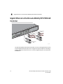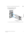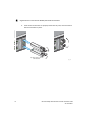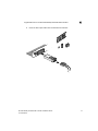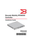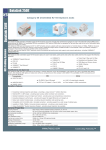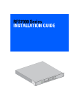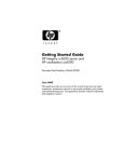
1
®
Brocade Mobility
RFS7000-GR Controller
Installation Guide
Supporting software release 4.1.0.0-040GR and later
53-1001946-01
Copyright © 2010 Brocade Communications Systems, Inc. All Rights Reserved.
Brocade, the B-wing symbol, BigIron, DCX, Fabric OS, FastIron, IronPoint, IronShield, IronView, IronWare, JetCore,
NetIron, SecureIron, ServerIron, StorageX, and TurboIron are registered trademarks, and DCFM, Extraordinary
Networks, and SAN Health are trademarks of Brocade Communications Systems, Inc., in the United States and/or in
other countries. All other brands, products, or service names are or may be trademarks or service marks of, and are
used to identify, products or services of their respective owners.
Notice: This document is for informational purposes only and does not set forth any warranty, expressed or implied,
concerning any equipment, equipment feature, or service offered or to be offered by Brocade. Brocade reserves the
right to make changes to this document at any time, without notice, and assumes no responsibility for its use. This
informational document describes features that may not be currently available. Contact a Brocade sales office for
information on feature and product availability. Export of technical data contained in this document may require an
export license from the United States government.
The authors and Brocade Communications Systems, Inc. shall have no liability or responsibility to any person or entity
with respect to any loss, cost, liability, or damages arising from the information contained in this book or the computer
programs that accompany it.
Brocade Communications Systems, Incorporated
Corporate and Latin American Headquarters
Brocade Communications Systems, Inc.
130 Holger Way
San Jose, CA 95134
Tel: 1-408-333-8000
Fax: 1-408-333-8101
E-mail: [email protected]
Asia-Pacific Headquarters
Brocade Communications Systems China HK, Ltd.
No. 1 Guanghua Road
Chao Yang District
Units 2718 and 2818
Beijing 100020, China
Tel: +8610 6588 8888
Fax: +8610 6588 9999
E-mail: [email protected]
European Headquarters
Brocade Communications Switzerland Sàrl
Centre Swissair
Tour B - 4ème étage
29, Route de l'Aéroport
Case Postale 105
CH-1215 Genève 15
Switzerland
Tel: +41 22 799 5640
Fax: +41 22 799 5641
E-mail: [email protected]
Asia-Pacific Headquarters
Brocade Communications Systems Co., Ltd. (Shenzhen
WFOE)
Citic Plaza
No. 233 Tian He Road North
Unit 1308 – 13th Floor
Guangzhou, China
Tel: +8620 3891 2000
Fax: +8620 3891 2111
E-mail: [email protected]
Document History
Title
Publication number
Summary of changes
Date
Brocade Mobility RFS7000-GR
Controller Installation Guide
53-1001946-01
New document
Sept 2010
1 Introduction
1
Package contents . . . . . . . . . . . . . . . . . . . . . . . . . . . . . . . . . . . . . . . . . . . . . . . . . . . . .1
Document conventions . . . . . . . . . . . . . . . . . . . . . . . . . . . . . . . . . . . . . . . . . . . . . . . .2
Warnings . . . . . . . . . . . . . . . . . . . . . . . . . . . . . . . . . . . . . . . . . . . . . . . . . . . . . . . . . . . .2
Site preparation . . . . . . . . . . . . . . . . . . . . . . . . . . . . . . . . . . . . . . . . . . . . . . . . . . . . . .3
2 Specifications
5
Physical specifications . . . . . . . . . . . . . . . . . . . . . . . . . . . . . . . . . . . . . . . . . . . . . . . . .5
Power cord specifications . . . . . . . . . . . . . . . . . . . . . . . . . . . . . . . . . . . . . . . . . . . . . .5
Power protection . . . . . . . . . . . . . . . . . . . . . . . . . . . . . . . . . . . . . . . . . . . . . . . . . . . . . . . . . . . 5
3 LED Codes
7
System status LEDs . . . . . . . . . . . . . . . . . . . . . . . . . . . . . . . . . . . . . . . . . . . . . . . . . . .8
Start up / POST (primary system or redundant system) . . . . . . . . . . . . . . . . . . . . . . . . . . . . 8
Controller status (primary system) . . . . . . . . . . . . . . . . . . . . . . . . . . . . . . . . . . . . . . . . . . . . . 8
Controller status (redundant system) . . . . . . . . . . . . . . . . . . . . . . . . . . . . . . . . . . . . . . . . . . 9
Fan LED . . . . . . . . . . . . . . . . . . . . . . . . . . . . . . . . . . . . . . . . . . . . . . . . . . . . . . . . . . . . . . . . . . 10
Temperature status LED . . . . . . . . . . . . . . . . . . . . . . . . . . . . . . . . . . . . . . . . . . . . . . . . . . . . . 10
RJ-45 gigabit Ethernet LEDs . . . . . . . . . . . . . . . . . . . . . . . . . . . . . . . . . . . . . . . . . . . .11
RJ-45 port speed LED . . . . . . . . . . . . . . . . . . . . . . . . . . . . . . . . . . . . . . . . . . . . . . . . . . . . . . . 11
RJ-45 port status LED . . . . . . . . . . . . . . . . . . . . . . . . . . . . . . . . . . . . . . . . . . . . . . . . . . . . . . . 11
SFP gigabit Ethernet LEDs . . . . . . . . . . . . . . . . . . . . . . . . . . . . . . . . . . . . . . . . . . . . . .12
SFP port speed LED . . . . . . . . . . . . . . . . . . . . . . . . . . . . . . . . . . . . . . . . . . . . . . . . . . . . . . . . . 12
SFP port status LED . . . . . . . . . . . . . . . . . . . . . . . . . . . . . . . . . . . . . . . . . . . . . . . . . . . . . . . . . 12
Out of band management port LEDs . . . . . . . . . . . . . . . . . . . . . . . . . . . . . . . . . . . . .13
Out of band management port speed LED . . . . . . . . . . . . . . . . . . . . . . . . . . . . . . . . . . . . . . 13
Out of band management port status LED . . . . . . . . . . . . . . . . . . . . . . . . . . . . . . . . .13
4 Hardware Setup
15
Cabling information . . . . . . . . . . . . . . . . . . . . . . . . . . . . . . . . . . . . . . . . . . . . . . . . . . .15
Gigabit Ethernet on the Brocade Mobility RFS7000-GR Controller . . . . . . . . . . . . .16
Installing Gigabit Ethernet SFPs . . . . . . . . . . . . . . . . . . . . . . . . . . . . . . . . . . . . . . . . . . . . . . . 17
Rack mount instructions . . . . . . . . . . . . . . . . . . . . . . . . . . . . . . . . . . . . . . . . . . . . . . .20
Brocade Mobility RFS7000-GR Controller console port setup . . . . . . . . . . . . . . . . .20
Supplying power to the Brocade Mobility RFS7000-GR Controller . . . . . . . . . . . . . .22
Brocade Mobility RFS7000-GR Controller Installation Guide
53-1001946-01
iii
Verifying the installation . . . . . . . . . . . . . . . . . . . . . . . . . . . . . . . . . . . . . . . . . . . . . . . 22
5 Secure Installation Procedure
25
Command line interface login procedure for the wireless controller . . . . . . . . . . . . 25
Changing default wireless controller parameters . . . . . . . . . . . . . . . . . . . . . . . . . . . 26
6 Regulatory Information
31
Country selection . . . . . . . . . . . . . . . . . . . . . . . . . . . . . . . . . . . . . . . . . . . . . . . . . . . . . 31
Laser devices - Gigabit Ethernet SFP option . . . . . . . . . . . . . . . . . . . . . . . . . . . . . . 31
Radio frequency interference requirements - FCC . . . . . . . . . . . . . . . . . . . . . . . . . . 32
Radio frequency interference requirements - Canada . . . . . . . . . . . . . . . . . . . . . . . 32
CE marking and European Economic Area (EEA) . . . . . . . . . . . . . . . . . . . . . . . . . . . 33
Statement of compliance . . . . . . . . . . . . . . . . . . . . . . . . . . . . . . . . . . . . . . . . . . . . . . . . . . . . 33
Waste Electrical and Electronic Equipment (WEEE) . . . . . . . . . . . . . . . . . . . . . . . . . 33
iv
Brocade Mobility RFS7000-GR Controller Installation Guide
53-1001946-01
About This Document
In this chapter
• Audience . . . . . . . . . . . . . . . . . . . . . . . . . . . . . . . . . . . . . . . . . . .
• Supported hardware and software . . . . . . . . . . . . . . . . . . . . . .
• Document conventions. . . . . . . . . . . . . . . . . . . . . . . . . . . . . . . .
• Contacting Brocade . . . . . . . . . . . . . . . . . . . . . . . . . . . . . . . . . .
• Warranty coverage . . . . . . . . . . . . . . . . . . . . . . . . . . . . . . . . . .
v
v
vi
vi
vii
Audience
This document is designed for system administrators with a working knowledge of
Layer 2 and Layer 3 switching and routing.
If you are using a Brocade Layer 3 Switch, you should be familiar with the following
protocols if applicable to your network – IP, RIP, OSPF, BGP, ISIS, IGMP, PIM, and
VRRP.
Supported hardware and software
The following hardware platforms are supported by this release of this guide:
• Brocade Mobility RFS7000-GR Controller
The following software version is supported by this release of this guide:
• Software version 4.1.0.0-040GR and later
Brocade Mobility RFS7000-GR Controller Installation Guide
53-1001946-01
v
Document conventions
This section describes text formatting conventions and important notice formats
used in this document.
Notes, cautions, and warnings
The following notices and statements are used in this manual. They are listed below
in order of increasing severity of potential hazards.
NOTE
A note provides a tip, guidance or advice, emphasizes important information, or
provides a reference to related information.
CAUTION
A Caution statement alerts you to situations that can be potentially
hazardous to you or cause damage to hardware, firmware, software, or
data.
DANGER
A Danger statement indicates conditions or situations that can be
potentially lethal or extremely hazardous to you. Safety labels are also
attached directly to products to warn of these conditions or situations.
Contacting Brocade
When contacting Brocade support, please provide the following information:
• Serial number of the unit
• Model number or product name
• Software version
vi
Brocade Mobility RFS7000-GR Controller Installation Guide
53-1001946-01
Customer Support Web Site
Brocade Support Central Web site, located at www.brocade.com/support provides
information and online assistance including developer tools, software downloads,
product manuals and online repair requests.
Downloads
http://www.brocade.com/support/
Manuals
http://www.brocade.com/support/
Because quality is our first concern at Brocade, we have made every effort to
ensure the accuracy and completeness of this document. However, if you find an
error or an omission, or you think that a topic needs further development, we want
to hear from you. Forward your feedback to: [email protected].
Provide the title and version number and as much detail as possible about your
comment, including the topic heading and page number and your suggestions for
improvement.
Email and telephone access
Go to http://www.brocade.com/services-support/index.page for e-mail and
telephone contact information.
Warranty coverage
Contact Brocade Communications Systems using any of the methods listed above
for information about the standard and extended warranties.
Brocade Mobility RFS7000-GR Controller Installation Guide
53-1001946-01
vii
viii
Brocade Mobility RFS7000-GR Controller Installation Guide
53-1001946-01
Chapter
1
Introduction
In this chapter
• Package contents . . . . . . . . . . . . . . . . . . . . . . . . . . . . . . . . . . . .
• Document conventions. . . . . . . . . . . . . . . . . . . . . . . . . . . . . . . .
• Warnings . . . . . . . . . . . . . . . . . . . . . . . . . . . . . . . . . . . . . . . . . . .
• Site preparation . . . . . . . . . . . . . . . . . . . . . . . . . . . . . . . . . . . . .
1
2
2
3
The Brocade Mobility RFS7000-GR Controller is a high-performance member of
Brocade’s wireless controller family. The Brocade Mobility RFS7000-GR Controller
provides centralized Wireless LAN (WLAN) configuration and management by
coalescing a network “intelligence” previously spread across physically distributed
access points. By replacing access points with simpler access ports (or “thin”
access points), the Brocade Mobility RFS7000-GR Controller becomes a WLAN’s
single point of contact, thus reducing wireless networking complexity by moving
management out of the ceiling and into the wiring closet. In addition, through the
use of patented Virtual AP architecture, the Brocade Mobility RFS7000-GR
Controller lets you create multiple WLANs without changing or adding to the existing
wired network infrastructure.
This document is written for the network device installer.
Package contents
Inspect the package contents and report any missing or damaged items to your
sales representative. The package should contain the following:
• Brocade Mobility RFS7000-GR Controller with rack brackets and tamper
evident labels installed
• Console Cable
• Brocade Mobility RFS7000-GR Controller Installation Guide (this document)
• China RoHS compliance document
Brocade Mobility RFS7000-GR Controller Installation Guide
53-1001946-01
1
1
Document conventions
Document conventions
The following graphical alerts are used in this document to indicate notable
situations:
NOTE
Tips, hints, or special requirements that you should take note of.
CAUTION
Care is required. Disregarding a caution can result in data loss or
equipment malfunction.
DANGER
Indicates a condition or procedure that could result in personal injury
or equipment damage.
Warnings
• Read all installation instructions and site survey reports, and verify correct
equipment installation before connecting the system to its power source.
• Remove jewelry and watches before installing this equipment.
• Install the equipment in a rack with adequate dimensions and weight
allowances.
• Verify the rack is anchored and cannot tip over or break away from its
mountings.
•
•
•
•
•
2
Verify the unit is grounded before connecting it to the power source.
Verify any device connected to this unit is properly wired and grounded.
Connect all power cords to a properly wired and grounded electrical circuit.
Verify the electrical circuits have appropriate overload protection.
Attach only approved power cords to the device.
Brocade Mobility RFS7000-GR Controller Installation Guide
53-1001946-01
Site preparation
1
• Brocade strongly recommends the use of an Uninterruptible Power Supply
(UPS) that supports the IP-RFS7000 power rating. Not using a UPS can result in
data loss or equipment damage due to a power surge or power failure.
• Verify that the power connector and socket are accessible at all times during
the operation of the equipment.
• Do not work with power circuits in dimly lit spaces.
• Do not install this equipment or work with its power circuits during
thunderstorms or other weather conditions that could cause a power surge.
• Verify there is adequate ventilation around the device, and ambient
temperatures meet equipment operation specifications.
Site preparation
• Consult your site survey and network analysis reports to determine specific
equipment placement, port capacity, power drops, and so on.
•
•
•
•
•
•
•
Assign installation responsibility to the appropriate personnel.
Identify where all installed components are located.
Verify appropriate rack mounting requirements.
Provide a sufficient number of power drops for your equipment.
Ensure adequate, dust-free ventilation to all installed equipment.
Identify and prepare Ethernet and console port connections.
Verify that cable lengths are within the maximum allowable distances for
optimal signal transmission.
• Verify that the Brocade Mobility RFS7000-GR Controller is powered through an
Uninterruptible Power Supply (UPS).
Brocade Mobility RFS7000-GR Controller Installation Guide
53-1001946-01
3
1
4
Site preparation
Brocade Mobility RFS7000-GR Controller Installation Guide
53-1001946-01
Chapter
2
Specifications
In this chapter
• Physical specifications . . . . . . . . . . . . . . . . . . . . . . . . . . . . . . . . 5
• Power cord specifications. . . . . . . . . . . . . . . . . . . . . . . . . . . . . . 5
Physical specifications
Width
440mm (17.32 in)
Height
44.45mm (1.75 in)
Depth
390.8mm (15.38 in)
Weight
6.12 Kg (13.5 lbs)
Operating Temperature
0°C - 40°C
Operating Humidity
5% - 85% RH, non-condensing
Operating Altitude
3 km (10000 ft)
Power cord specifications
A power cord is not supplied with the controller. Use only a correctly rated power
cord certified (as appropriate) for the country of operation.
Power protection
• If possible, use a circuit dedicated to data processing equipment. Commercial
electrical contractors are familiar with wiring for data processing equipment
and can help with the load balancing of these circuits.
Brocade Mobility RFS7000-GR Controller Installation Guide
53-1001946-01
5
2
Power cord specifications
• Install surge protection. Be sure to use a surge protection device between the
electricity source and the Brocade Mobility RFS7000-GR Controller.
• Install an Uninterruptible Power Supply (UPS). A UPS provides continuous
power during a power outage. Some UPS devices have integral surge
protection. UPS equipment requires periodic maintenance to ensure reliability.
A UPS of the proper capacity for the data processing equipment must be
purchased.
6
Brocade Mobility RFS7000-GR Controller Installation Guide
53-1001946-01
Chapter
LED Codes
3
In this chapter
• System status LEDs . . . . . . . . . . . . . . . . . . . . . . . . . . . . . . . . . . 8
• RJ-45 gigabit Ethernet LEDs . . . . . . . . . . . . . . . . . . . . . . . . . . 11
• SFP gigabit Ethernet LEDs . . . . . . . . . . . . . . . . . . . . . . . . . . . . 12
• Out of band management port LEDs. . . . . . . . . . . . . . . . . . . . 13
• Out of band management port status LED . . . . . . . . . . . . . . . 13
The Brocade Mobility RFS7000-GR Controller has four vertically-stacked LEDs on its
front panel. Each of the controller’s Gigabit Ethernet ports have two status LEDs.
These LEDs display two colors (green & amber), and three lit states (solid, blinking,
and off). The following tables decode the combinations of LED colors and states for
the System Status LEDs and the Gigabit Ethernet LEDs.
Brocade Mobility RFS7000-GR Controller Installation Guide
53-1001946-01
7
3
System status LEDs
System status LEDs
6\VWHP6WDWXV
6\VWHP6WDWXV
)DQVWDWXV
7HPSHUDWXUHVWDWXV
Start up / POST (primary system or redundant system)
System Status 1 LED
System Status 2 LED
Event
Off
Off
Power off
Green Blinking
Green Blinking
Power On Self Test (POST) running
Green Solid
Green Blinking
POST succeeded (Operating System Loading)
Green Solid
Off
POST succeeded (Normal Operation)
Amber Blinking
Off
POST Failure
Alternating Green Blinking
& Amber Blinking
Alternating Green Blinking
& Amber Blinking
Boot Up Error: Device has an invalid checksum
NOTE
During controller start up, the Temperature status LED will be lit Solid Amber. This is
normal behavior and does not indicate an error. At the completion of start up the
Temperature Status LED will switch to Solid Green.
Controller status (primary system)
System Status 1 LED
System Status 2 LED
Event
Off
Off
Power off
Green Solid
Off
No Redundancy Feature Enabled
8
Brocade Mobility RFS7000-GR Controller Installation Guide
53-1001946-01
3
System status LEDs
System Status 1 LED
System Status 2 LED
Event
Green Solid
Green Solid
Redundancy Feature Enabled
Actively Adopting Access Ports
Green Solid
Amber Blinking
No License to adopt Access Ports
or
No Country Code configured on the controller
or
License and Country Code configured, but no
APs adopted
Controller status (redundant system)
System Status 1 LED
System Status 2 LED
Event
Off
Off
Power off
Green Solid
Off
No Redundancy Feature Enabled
Green Blinking
Green Solid
Redundant System failed over and adopting
ports
Green Blinking
Alternating Green Blinking
& Amber Blinking
Redundant System not failed over.
Green Solid
Amber Blinking
No License to adopt Access Ports
or
No Country Code configured on the controller
or
License and Country Code configured, but no
APs adopted
Brocade Mobility RFS7000-GR Controller Installation Guide
53-1001946-01
9
3
System status LEDs
Fan LED
Fan LED
Event
Off
System Off / POST Start
Green Blinking
POST in Process
Green Solid
All System Fans Normal Operation
Amber Solid
Redundant Cooling Failure
System Operational
Amber Blinking
System Cooling Failure
System will be held in reset until the issue is
resolved
Temperature status LED
Temperature LED
Event
Off
System Off
Green Solid
Ambient Inlet Temperature is within specified
operating limit
Amber Solid
Ambient Inlet Temperature is near the
maximum operating temperature
During controller start up this LED will be lit
Solid Amber. This is normal behavior and does
not indicate an error.
Amber Blinking
10
Ambient Inlet Temperature is above the
maximum specified operating temperature
System will be held in reset until the issue is
resolved
Brocade Mobility RFS7000-GR Controller Installation Guide
53-1001946-01
3
RJ-45 gigabit Ethernet LEDs
RJ-45 gigabit Ethernet LEDs
3RUW
VSHHG
3RUW
VWDWXV
V\PB
3RUW
3RUW
VSHHG VWDWXV
RJ-45 port speed LED
Port Speed LED
Event
Off
10 Mbps
Green Solid
100 Mbps
Green Blinking
1000 Mbps
Amber Blinking
Port Fault
RJ-45 port status LED
Port Status LED
Event
Off
No Link or Administratively shut down
Green Solid
Link present
Green Blinking
Activity: Transmit and Receive
Amber Blinking
Link Fault
Brocade Mobility RFS7000-GR Controller Installation Guide
53-1001946-01
11
3
SFP gigabit Ethernet LEDs
SFP gigabit Ethernet LEDs
3RUW
3RUW
VSHHG VWDWXV
8SSHU
3RUW
V\PB
/RZHU
3RUW
SFP port speed LED
Port Speed LED
Event
Green Blinking
1000 Mbps
Amber Blinking
Module or Tx/Rx Fault Loss
SFP port status LED
12
Port Status LED
Event
Off
No Link or Administratively shut down
Green Solid
Link present / Operational
Amber Blinking
Module or Tx/Rx Fault Loss
Brocade Mobility RFS7000-GR Controller Installation Guide
53-1001946-01
3
Out of band management port LEDs
Out of band management port LEDs
3RUW
VSHHG
3RUW
VWDWXV
V\PB
Out of band management port speed LED
Port Speed LED
Event
Off
10 Mbps
Green Solid
100 Mbps
Amber Blinking
Port Fault
Out of band management port status LED
Port Status LED
Event
Off
No Link
Green Solid
Link present
Green Blinking
Activity: Transmit and Receive
Amber Blinking
Link Fault
Brocade Mobility RFS7000-GR Controller Installation Guide
53-1001946-01
13
3
14
Out of band management port status LED
Brocade Mobility RFS7000-GR Controller Installation Guide
53-1001946-01
Chapter
4
Hardware Setup
This chapter contains the following sections:
• Cabling information . . . . . . . . . . . . . . . . . . . . . . . . . . . . . . . . . 15
• Gigabit Ethernet on the Brocade Mobility RFS7000-GR Controller 16
• Rack mount instructions . . . . . . . . . . . . . . . . . . . . . . . . . . . . . 20
• Brocade Mobility RFS7000-GR Controller console port setup 20
• Supplying power to the Brocade Mobility RFS7000-GR Controller 22
• Verifying the installation . . . . . . . . . . . . . . . . . . . . . . . . . . . . . . 22
Cabling information
&RQVROH
2XWRI%DQG
0DQDJHPHQW
86%
86%
&RPSDFW)ODVK
*LJDELW
6)3
3RUW
*LJDELW
(WKHUQHW
3RUW
*LJDELW
6)3
3RUW
*LJDELW
(WKHUQHW
3RUW
*LJDELW
6)3
3RUW
*LJDELW
(WKHUQHW
3RUW
*LJDELW
6)3
3RUW
*LJDELW
(WKHUQHW
3RUW
V\PB
NOTE
The USB and Compact Flash ports are not available for the GR release of this
product and are covered with tamper evident labels.
The Brocade Mobility RFS7000-GR Controller has four RJ-45 Gigabit Ethernet ports,
four Gigabit SFP (fiber) ports, one Out-of-band management port and one Console
connector. The above diagram shows each of those ports and the cables or devices
attached to them. The sections that follow describe detailed connection and
cabling information for each port.
Brocade Mobility RFS7000-GR Controller Installation Guide
53-1001946-01
15
4
Gigabit Ethernet on the Brocade Mobility RFS7000-GR Controller
Gigabit Ethernet on the Brocade Mobility RFS7000-GR
Controller
*LJDELW(WKHUQHW
5-V
*LJDELW(WKHUQHW
6)3V
V\PB
The Brocade Mobility RFS7000-GR Controller has four RJ-45 Gigabit Ethernet ports
and four Gigabit SFP (fiber optic) ports. Using the RJ-45 ports requires connecting a
Category-6 Ethernet cable to the port. To use the Gigabit SFP ports, first install the
SFP Modules.
16
Brocade Mobility RFS7000-GR Controller Installation Guide
53-1001946-01
Gigabit Ethernet on the Brocade Mobility RFS7000-GR Controller
4
Installing Gigabit Ethernet SFPs
1. Open the bail on the transceiver.
2SHQEDLOWRLQVHUWRUUHPRYH
6)3WUDQVFHLYHU
2. Insert each of the SFP transceivers into the corresponding ports on the switch.
Brocade Mobility RFS7000-GR Controller Installation Guide
53-1001946-01
17
4
Gigabit Ethernet on the Brocade Mobility RFS7000-GR Controller
3. Once the SFP transceivers are properly seated in their ports, close the bails to
lock the transceivers in place.
2SHQEDLOWRLQVHUWRUUHPRYH
6)3WUDQVFHLYHU
18
V\PB
Brocade Mobility RFS7000-GR Controller Installation Guide
53-1001946-01
Gigabit Ethernet on the Brocade Mobility RFS7000-GR Controller
4
4. Insert the fiber optic cables into the installed transceivers.
Brocade Mobility RFS7000-GR Controller Installation Guide
53-1001946-01
19
4
Rack mount instructions
Rack mount instructions
To install the Brocade Mobility RFS7000-GR Controller in a rack:
1. The rack mounting brackets are installed at the factory. No additional steps are
needed.
2. Attach the brackets to the rack using screws appropriate for your rack’s
mounting holes.
Brocade Mobility RFS7000-GR Controller console port
setup
To add the Brocade Mobility RFS7000-GR Controller to the network and prepare it
for initial configuration:
20
Brocade Mobility RFS7000-GR Controller Installation Guide
53-1001946-01
Brocade Mobility RFS7000-GR Controller console port setup
4
1. Using the supplied console cable (pictured below), connect the Brocade
Mobility RFS7000-GR Controller serial port to an RS-232 (DB-9) serial port on a
separate computer (the “configuration computer”).
2. On the configuration computer, configure a terminal emulation application
(such as HyperTerminal) as follows:
Terminal Type
VT-100
Port
COM port
Terminal Settings
19200bps transfer rate
8 data bits
no parity
1 stop bit
no flow control
no hardware compression
Brocade Mobility RFS7000-GR Controller Installation Guide
53-1001946-01
21
4
Supplying power to the Brocade Mobility RFS7000-GR Controller
Supplying power to the Brocade Mobility RFS7000-GR
Controller
$&LQOHW
5DFNPRXQW
EUDFNHW
V\PB
1. Plug an approved AC power cord into the power connector at the back of the
Brocade Mobility RFS7000-GR Controller.
2. Plug the cord into a standard AC outlet with a voltage range of 100 to 240 VAC.
CAUTION
An improper shutdown can render the Brocade Mobility RFS7000-GR
Controller inoperable such that it could require service by Brocade
Support. Do not remove AC power without first following the shutdown
procedure. An abrupt loss of power can corrupt the information stored
on the device.
Verifying the installation
View the LEDs on the front panel of the Brocade Mobility RFS7000-GR Controller to
ensure the device is functioning properly. The normal LED pattern follows this path:
22
Brocade Mobility RFS7000-GR Controller Installation Guide
53-1001946-01
Verifying the installation
4
• During the Power On Self Test (POST), the System 1 and System 2 LEDs both
blink green.
• If the POST test fails, the System 1 LED will blink amber. If the POST test
succeeds, the System 1 LED will be lit solid green.
• As the software is initialized, the System 2 LED will blink green.
• After the software has finished initializing, the System 1 LED will be lit solid
green and the bottom System 2 LED will be off.
Other LED codes indicate the presence (or absence) of different standby states, or
errors. A guide to the Brocade Mobility RFS7000-GR Controller LEDs codes is
provided in LED Codes on page 3-7.
Brocade Mobility RFS7000-GR Controller Installation Guide
53-1001946-01
23
4
24
Verifying the installation
Brocade Mobility RFS7000-GR Controller Installation Guide
53-1001946-01
Chapter
Secure Installation Procedure
5
In this chapter
• Command line interface login procedure for the wireless controller 25
• Changing default wireless controller parameters. . . . . . . . . . 26
This installation procedure explains how to login to the Command Line Interface for
initial configuration.
Through this process the wireless controller is configured with a set of default
values for specific features. These default values should be changed in order to
maintain the security of the wireless users and access to the controller.
Command line interface login procedure for the
wireless controller
1. Enter “cli” at login prompt
RFS7000 login: cli
This device is running on FIPS mode.
Attention:
This is a protected and private wireless system. No un-authorized
access allowed. You must have proper rights to access and manage
this system from the authorized personnel.
Do you want to proceed? (y/n):y
2. Enter “admin” at username prompt
Username: admin
3. Enter “0umP.s45fIOD6” at Password prompt below. (“0umP.s45fIOD6 is the
default password for admin user).
Password:
4. Once Username and Password credentials are validated, the controller will
prompt to change the default password to a new value. Please change the
default password of the admin user.
Brocade Mobility RFS7000-GR Controller Installation Guide
53-1001946-01
25
5
Changing default wireless controller parameters
Password is same as default password, please change the password
Enter old password:
<type old password>
Enter new password:
<type new password>
Re Enter new password:
<type new password>
Password for user 'admin' changed successfully
RFS7000>
5. Once Username and Password credentials are validated, the below prompt will
returned. Enter “Enable” to get into execution mode.
RFS7000>enable
RFS7000#
6. To get into configuration mode, enter “configure terminal” at “exec-mode”
prompt above.
RFS7000# configure terminal
Enter configuration commands, one per line. End with CNTL/Z.
RFS7000(config)#
Changing default wireless controller parameters
The various default parameters which must be changed to operate the wireless
controller in a secured operational mode are listed below:
1. Change the SNMP users (snmpoperator, snmpmanager and snmptrap) default
passwords to new values.
Go to the global configuration context and change the default passwords of
SNMP for all the 3 SNMP users.
RFS7000(config)#snmp-server user snmpmanager v3 encrypted des
auth md5 <password>RFS7000(config)#snmp-server user snmpoperator
v3 encrypted des auth md5 <password>
RFS7000(config)#snmp-server user snmptrap v3 encrypted des auth
md5 <password>
2. By default SNMP manager is disabled and need to start SNMP manager for GUI
access. Go to the global configuration context and start SNMP manager.
RFS7000(config)#snmp-server manager v3
3. Change the default Admin password ( Superuser) .
RFS7000(config)#username admin password 0 a%defMyj
26
Brocade Mobility RFS7000-GR Controller Installation Guide
53-1001946-01
Changing default wireless controller parameters
5
NOTE
The password a%defMyj is only an example. Enter a unique password in place of
this example.
4. Country code must be set to the appropriate country in order to have proper
channel of operations. Access Points are adopted after the country code is set.
a.
Enter “wireless configuration mode”
RFS7000(config)#wireless
b.
Execute the following in wireless configuration mode.
RFS7000(config-wireless)#country-code us
CAUTION
Select only the country in which you are using the device. Any other
selection may make the operation of this device illegal.
5. The default SSID for all WLANs (wireless LANs) in the system is “101”. This
SSID should be changed to ensure secure operation.
a.
Go to “wireless configuration mode” and execute the following:
RFS7000(config-wireless)#wlan 1 ssid myOwnSsid
NOTE
The SSID of myOwnSsid is only an example. Enter a unique SSID in place of
this example.
6. The default encryption for the WLAN must be changed before enabling the
WLAN.
a.
Select the Encryption type. The default encryption is AES/CCMP.
RFS7000(config-wireless)#wlan 1 encryption-type ccmp
b.
By default pre-shared key is used for AES/CCMP encryption with a default
key used for all WLANs. This key must be changed before enabling the
WLAN.
RFS7000(config-wireless)#wlan 1 dot11i key 0
acdefab12345678abcdefab12345678abcdefab12345678abcdefab123456
78
Brocade Mobility RFS7000-GR Controller Installation Guide
53-1001946-01
27
5
Changing default wireless controller parameters
NOTE
The pre-shared key:
acdefab12345678abcdefab12345678abcdefab12345678abcdefab
12345678 is only an example. Enter a unique pre-shared key in place of this
example.
7.
Self Signed certificates should be replaced with a private certificate.
a.
The controller ships with a default trust point using a default self-signed
certificate. This certificate is associated with the hotspot and onboard
RADIUS server. This certificate should be replaced with a valid certificate
from a Certificate Authority.
b.
The following command will show the existing self-signed certificate.
RFS7000(config)#show crypto pki trustpoints
Trustpoint :default-trustpoint
----------------------------------------------Server certificate configured
Subject Name:
Common Name:
Brocade
Organizational Unit: EWLAN
Organization:
Enterprise Mobility
Location:
San Jose
State:
CA
Country:
US
Issuer Name:
Common Name:
Brocade
Organizational Unit: EWLAN
Organization:
Enterprise Mobility
Location:
San Jose
State:
CA
Country:
US
Valid From:
Jan 29 15:13:44 2008 GMT
Valid Until: Jan 28 15:13:44 2009 GMT
c.
Create a new trust point.
RFS7000(config)#crypto pki trustpoint externalCert
RFS7000(config-trustpoint)#subject-name motoFips US CA "San
Jose" Moto "WLAN division"
RFS7000(config)#crypto pki enroll externalCert request
d.
The following command displays the above created trust point and
certificate request:
RFS7000(config)#show crypto pki request externalCert
28
Brocade Mobility RFS7000-GR Controller Installation Guide
53-1001946-01
Changing default wireless controller parameters
5
-----BEGIN CERTIFICATE REQUEST----MIIB2jCCAUMCAQAwZzELMAkGA1UEBhMCVVMxCzAJBgNVBAgTAkNBMREwDwYDV
QQH
EwhTYW4gSm9zZTENMAsGA1UEChMETW90bzEWMBQGA1UECxMNV0xBTiBkaXZpc
2lv
bjERMA8GA1UEAxMIbW90b0ZpcHMwgZ8wDQYJKoZIhvcNAQEBBQADgY0AMIGJA
oGB
AMHr9U1XAEhhEInvVHsyFkvjnKcX7RVbiC01HkGrBMTipKZMx/vQ/zbHlzNcj
72k
FwH9aJeI68tOEjvOK/9287UUqt9T73cti+VZf9h8rmvWTSQsOZ5GogGhYvc/n
Jee
mQF7OSjXi2J1CjkIhQTarpGv9/TW2RSWOGFa5wtwbt0BAgMBAAGgMzAxBgkqh
kiG
9w0BCQ4xJDAiMAsGA1UdDwQEAwIEsDATBgNVHSUEDDAKBggrBgEFBQcDATANB
gkq
hkiG9w0BAQUFAAOBgQCHPKPXA/0XQQts10hPaEsgtF723kBYumMjL0gYDW1aJ
kUT
wh+6JD5hhjPiwgTjRBM5wtBlvGbVltunnRy0ukXWxgJG4p4lc85clF0n24Xkq
D7i
3p9A5aGN0Bruchtu/ToTEvKjqd7hwkcH96V6JZDW++aSVdT5lUxr8QDhg9GwN
g==
-----END CERTIFICATE REQUEST-----
e.
Export this certificate request to an external machine/server where the
request can be submitted to the Certificate Authority as shown below.
RFS7000(config)#crypto pki export externalCert request
sftp://[email protected]/RF7000-server-req
f.
Import the CA certificate obtained from the external signing authority using
SFTP as shown below.
RFS7000(config)#crypto pki authenticate externalCert
sftp://[email protected]/CA_Cert.der
NOTE
In the above example code, the SFTP server IP Address is 10.10.10.10.
g.
Import the Server certificate obtained from external CA using SFTP.
RFS7000(config)#crypto pki import externalCert certificate
sftp://[email protected]/Serv_Cert.der
h.
Associate the newly created trustpoint with the hotspot feature using the
example below:
RFS7000(config)#no ip http secure-server
RFS7000(config)#ip http secure-trustpoint externalCert
Brocade Mobility RFS7000-GR Controller Installation Guide
53-1001946-01
29
5
Changing default wireless controller parameters
i.
Enable http and https access to the hotspot page:
RFS7000(config)#ip http secure-server
RFS7000(config)#ip http server
j.
Associate the newly created trustpoint with the onboard RADIUS server
using the example below:
RFS7000(config)#radius-server local
RFS7000(config-radsrv)#ca trust-point externalCert
RFS7000(config-radsrv)#server trust-point externalCert
k.
Restart the RADIUS server.
RFS7000(config)#service radius restart
l.
Write the changes to memory.
RFS7000(config)#write memory
30
Brocade Mobility RFS7000-GR Controller Installation Guide
53-1001946-01
Chapter
6
Regulatory Information
• Country selection . . . . . . . . . . . . . . . . . . . . . . . . . . . . . . . . . . .
• Laser devices - Gigabit Ethernet SFP option. . . . . . . . . . . . . .
• Radio frequency interference requirements - FCC . . . . . . . . .
• Radio frequency interference requirements - Canada . . . . . .
• CE marking and European Economic Area (EEA) . . . . . . . . . .
• Waste Electrical and Electronic Equipment (WEEE) . . . . . . . .
31
31
32
32
33
33
This regulatory section applies to the Mobility RFS7000 Controller.
All Brocade devices are designed to be compliant with rules and regulations in
locations they are sold and will be labeled as required.
Any changes or modifications to Brocade equipment, not expressly approved by
Brocade, could void the user’s authority to operate the equipment.
Country selection
Select only the country in which you are using the device. Any other selection will
make the operation of this device illegal.
!
Laser devices - Gigabit Ethernet SFP option
Complies with 21CFR1040.10 and 1040.11 except for deviations pursuant to Laser
Notice No. 50, dated July 26, 2001.
EN60825-1:1994+ A1:2002 +A2:2001
IEC60825-1:1993+A1:1997+A2:2001
The laser classification is marked on the device.
Brocade Mobility RFS7000-GR Controller Installation Guide
53-1001946-01
31
6
Radio frequency interference requirements - FCC
Class 1 Laser devices are not considered to be hazardous when used for their
intended purpose. The following statement is required to comply with US and
international regulations:
CAUTION
This is a class A product. In a domestic environment this product may
cause radio interference in which case the user may be required to
take adequate measures.
Radio frequency interference requirements - FCC
This equipment has been tested and found to comply with the limits for a Class A
digital device, pursuant to Part 15 of the FCC rules. These limits are designed to
provide reasonable protection against harmful interference when the equipment is
operated in commercial environment. This equipment generates, uses, and can
radiate radio frequency energy and, if not installed and used in accordance with the
instruction manual, may cause harmful interference to radio communications.
Operation of this equipment in a residential area is likely to cause harmful
interference in which case the user will be required to correct the interference at
his own expense.
Radio frequency interference requirements - Canada
This Class A digital apparatus complies with Canadian ICES-003.
Cet appareil numérique de la classe A est conforme à la norme NMB-003 du
Canada.
32
Brocade Mobility RFS7000-GR Controller Installation Guide
53-1001946-01
CE marking and European Economic Area (EEA)
6
CE marking and European Economic Area (EEA)
Statement of compliance
Brocade hereby declares that this device is in compliance with all the applicable
Directives, 2004/108/EC, 2006/95/EC. A Declaration of Conformity may be
obtained from http://www2symbol.com/doc/
Waste Electrical and Electronic Equipment (WEEE)
For information on WEEE, please go to:
http://www.brocade.com/sites/dotcom/company/corporate-responsibility/corpor
ate-citizenship/product-recycling/weee.page
Brocade Mobility RFS7000-GR Controller Installation Guide
53-1001946-01
33
6
34
Waste Electrical and Electronic Equipment (WEEE)
Brocade Mobility RFS7000-GR Controller Installation Guide
53-1001946-01