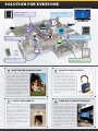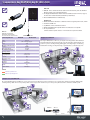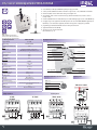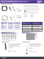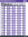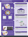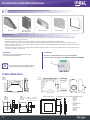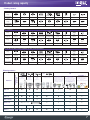
1
WIRELESS CONTROL SYSTEM www.elkoep.com ELKO EP COMPANY PRESENTATION COMPLEX SOLUTIONS FROM A SINGLE MANUFACTURER! The company ELKO EP, a Czech manufacturer of modular electronic devices, has been your partner in wired and wireless solutions for over two decades. Our product range has undergone dynamic development, from simple manufacture of modular devices to developing and implementing wireless solutions and sophisticated wired intelligent systems including multimedia control throughout your entire home. In the past year, we also achieved great progress in getting our systems to communicate with each other, which brings you unlimited possibilities and variations of electrical installations custom-made for your home. A major advantage and founding pillar of our work is our own development capacities and facilities, enabling us to have immediate interaction between you - our customers - and ourselves. We flexibly fine-tune all our products to satisfy not only strict standards, but especially their users in everyday life. Right now, we are working intensively on interconnecting all of our systems, and we are designing wide-ranging solutions for both new home constructions and existing wiring schemes. We are all accustomed to different standards, and everybody has the chance to raise theirs a few notches higher. We also feature our rich portfolio of control elements, including the award-winning wireless device RF Touch, elegant switches and outlets in a unified and timeless design, and the option of control through security keypads, notebooks, smart phones or iPADs. This is all possible, and at ELKO EP, it has now become a reality. RELAYS - Modular electronic devices www.elkoep.com A wide range of electronic modular devices, which bring new possibilities to home and office control, monitoring and security, as well as to industrial process control: time relays, installation contactors, staircase automatic switches, time switches clocks, dimmers, thermostats, power supplies units, control and signalling devices, GSM gates, etc. iNELS - Intelligent Electrical Installation System www.inels.com iNELS will transform your house into a timeless intelligent household. It will take charge of heating and air-conditioning regulation, lighting control and home appliance switching, while also providing perfect security for your home. Enjoy controlling your entire house via a TV screen thanks to iNELS Multimedia (iMM) or use the elegant iNELS Touch Panel (iTP). iNELS RF Control - Wireless control www.inels.com A unique wireless control system providing you perfect control over your home! The RF Control system enables you to control functions such as heating, lighting, electrical appliances and window shutters, all with a single touch. No demolition work, fast and easy installation, exclusive design of wireless wall switch buttons and other components. LOGUS90 - Home switches and sockets www.logus90.com We offer you exclusive switches, sockets and accessories in a standard plastic or metallic finish. However, there are also charming luxury frames from purely natural materials such as genuine wood, metal, granite or hardened glass. Be exceptional! SOLUTION FOR EVERYONE WIRELESS TOUCH CONTROL UNIT MULTIMEDIA EXTENSION RF KEY INTELLIGENT ELECTRICAL INSTALLATION SYSTEM WIRELESS CONTROL UNIT WITH DISPLAY RF PILOT WIRELESS SYSTEM MORE TIME FOR YOUR LOVED ONES With an intelligent wired/wireless solution, you have more time available for truly important moments. You can set the heating regulation up to a week ahead of time. Your home will take care of itself. The so-called vacation mode assures that your house will not freeze in the winter, but will not heat excessively either. You will also value the arrival/departure functions - where after entering a code at the entrance door, the individual mode of the recognized user starts. LIGHT AT YOUR SERVICE You can centrally switch, dim or create light scenes for all lights both outside and inside the home. We can dim all light sources (energy-saving, LED or fluorescent lamps, RGB strips). The arrival/departure function relieves you of having to check the whole house to see if you have really turned everything off. And when you simply have to leave in a hurry, you have control over lights thanks to remote Internet access - you see that your lights are not needlessly wasting energy. HOME SWITCHES AND SOCKETS LOGUS90 WE SEE TO YOUR SECURITY The system contains an alarm that can be connected to a security agency. Select simple home access - under the code on the keypad or via chip card. You now no longer need to worry about losing your keys - just change the code from time to time. You can password-protect your home in many levels (ex. preventing child access for safety reasons). Your home will inform you by SMS on changes to the status of your home. A NEW WAY TO LOOK AT TELEVISION We offer you the possibility of controlling the entire house through the television screen (regulation of lighting, heating, blinds - i.e. all elements connected in the iNELS system). You can create the plan for the room, floor or entire home just the way you like. Thanks to IP cameras, you have a clear view of what‘s going on in front of the house, in the children‘s room, or garage. You can see what your kids are currently watching on TV in the other room. You can also open the door remotely for invited visitors. iNELS SMART HOME SOLUTIONS We present you iNELS smart home solutions - it is a new brand of electrical solutions, including wireless and bus wiring system. With regard to the new possibility of combination these two solutions, we decided to create a brand that captures the dynamism, versatility, versatility, flexibility and also intelligence. CHOOSE FROM 20 REASONS THE ONES THAT MAKE YOUR LIFE EASIER! 10 REASONS TO OPT FOR BUS SYSTEM 1) ideal solution for new buildings 2) two-wire bus 3) bus once stretched you can always expand 4) security system, combined with detectors 5) remote control (PC, mobile phone applications) 6) imitation of presence 7) regulation depending on the weather 8) ecology and energy saving 9) modern trends in controling 10) media under control (can also be controlled via TV) 10 REASONS TO OPT FOR WIRELESS SYSTEM 1) installation without breaking the walls 2) could be moved any time - elements are not kept by wire but by the waves 3) any time expandable - actuators and drivers can increase exponentially 4) appropriate to existing installations 5) variable control - switch, keychain, remote control, touchscreen unit 6) centralized control - thanks to RF Touch 7) planning for the week ahead 8) combination with detectors - motion, smoke, opening windows/doors 9) controlling actuators as a group with a single touch 10) luxurious design SYSTEM INFRASTRUCTURE Air conditioning Thermal pump VideoZone 1 HDMI Converter RS485(232)/ Ethernet RS232 Weather station Satellite VideoZone 2 iMM Client Gyroscopic controller Gyroscopic controller iMM Client iNELS Touch Tablet iTP-B flush mounted RS232 optik cable Streamer Zesilovač IP outdoor video camera Miele AD iNELS Touch Tablet iTP-T (Android) IP indoor video camera Wifi iNELS Mobile Switch Wifi Internet Wifi Door lock Audio Zone player PC/Notebook Router BUS SYTEM Door communicator Central unit iMM Server (data storage) GSM communicator Controlling illumination Dimming lights Controller for shutters, blinds Temperature control Switching appliances 25.2 °C Control touchscreen device 4-channel wall switch Digital temperature controller Remote control with display 4-channel remote control Temperature actuator Detectors RF AP/USB /USB For communications with wireless system Switching actuator Dimming actuator Roll-blind actuator WIRELESS SYSTEM Touchscreen unit EST-2 CATALOGUE CONTENT Wireless control system Wireless communication via RF system Overview of RF Control wireless elements RF transmitters Controllers RF Touch-W - touch control unit for mounting on the surface RF Touch-B - touch control unit for mounting in an installation box RF Pilot- Remote Controller with display RFAP/USB - Flash drive with USB Virtual Touch NEW! RF iNELS/USB - Flash drive NEW! RF KEY - 4-channel remote controller as a Keychain RFWB-20/G - 2-channel wireless wall switch button in LOGUS90 design RFWB-40/G - 4-channel wireless wall switch button in LOGUS90 design RFTC-10/G - Digital temperature regulator in LOGUS90 design Converters RFIM - 20B - Universal transmitter module under switch/button RFIM - 40B - Universal transmitter module under switch/button RFSG - 1M - universal transmitter module. Supply voltage 230V, 1-module design RFTI - 10B - wireless temperature sensor, MINI design Elan-RF-003- Converter Ethernet to RF signal NEW! RFGSM-220 - multifunction GSM communicator NEW! Repeater RFRP - 20 - signal repeater in a wireless socket box RF meter RFPM-1 - electricity meter NEW! Detectors (see Overview of RF Control wireless elements, page 12) RF receivers Shutter actuators RFJA-12B /230VAC -2x switching 8A relay with protection RFJA-12B /24VDA - contactless switching Dimming actuators RFDSC-11 - single-function dimming socket, button dimmer NEW! RFDSC-71 - multifunction dimming socket, 7 functions NEW! RFDA-11B - single-function dimming actuator, 1 light scene RFDA-71B - multifunctional dimming actuator, 7 functions RFDEL-71B - RF dimmer for LED lamps and dimmable energy-saving fluorescent tubes RFDA-73M/RGB - dimming actuator for dimming LED and RGB LED strips NEW! Switching actuators RFSC-11 - single-function switched socket NEW! RFSC-61 - multifunction switched socket, 6 functions NEW! RFSA-11B - 1-channel single-function switching actuator RFSA-61B - 1-channel multifunction switching actuator RFSA-62B - 2-channel multifunction switching actuator RFSAI-61B - jednokanálový multifunkční spínací aktor s externím vstupem NEW! RFSA-61B - 1-channel multifunction switching actuator, module design RFSA-66M - 6-channel multifunction switching actuator, module design RFUS-11- single-channel single-function switching actuator with enhanced IP65 protection NEW! RFUS-61- single-channel multifunction switching actuator with enhanced IP65 protection NEW! Temperature actuators RFSTI-11B - switching actuator with temperature sensor RFSTI-11/G - switching actuator with temperature sensor, LOGUS90, manual control RFATV-1 - Wireless thermostat NEW! Analog actuator RFDAC - 71B - actuator with analog output 0(1) – 10V Accessories ALPHA AA 0–10V - Thermostat, DIML - dimmable control gear Temperature sensors, internal antenna, external antenna AN-E Additional information RF SETS - transmitter and receiver combinations Easy and quick program setting Use instructions and product dimensions Product loadability Wireless solution for your electrical installation 8-11 12-13 14-15 14-15 16-17 18 18 19 20 20 21 22 22 23 24 25 26-27 28 29 30 30 31 31 32 32 33 34-35 36 36 37 37 37 38 39 39 40 40 41 41 42 43 44 45 46 47 48 49 50-51 WIRELESS SYSTEM Your house at one touch WIRELESS TOUCH SCREEN CONTROL UNIT RANGE R ANGE Switching electrical devices on/off 200 m Light dimming RF PILOT- REMOTE CONTROL WITH DISPLAY FREQUENCY FREQU ENCY ENCY Heating regulation 868 M MHz Hz Air-conditioning control Shutter control Detector control WIRELESS COMMUNICATION What does wireless control bring you? • Switching of appliances or electrical devices remotely • Dimming lights, light scenes • Controlling shutters, awnings, outdoor blinds and blinds between windows • Controlling access gates, garage doors • Manual or automatic control - according to set program • Switching appliances in relation to reaction of employed detectors • Reaction to (unwanted) opening of a window or door • Reaction to movement of persons (wanted and unwanted) • Energy savings due to regulation of lights and heating • Installation is performed simply without any holes or cutting into the wall. Units (actuators) can be installed directly into a suitable installation cabinet, into a light cover, switchboard and anywhere the installation allows. • Flexible placement: ideal for installing in existing buildings, for reconstructions and new constructions as well: with the iNELS RF Control, you are not bound to the location of the switch, ex. when rearranging furniture. You can affix the wireless switch to glass, to a beam or just set it on the night stand and move it around wherever you like. RF TOUCH FOR COMFORTABLE CONTROL WITH A SINGLE TOUCH ILLUMINATION FROM ANY CHOSEN SPOT • Controlling lights from the terrace or opening the garage? Keychain - the remote control that you always have handy. • The universal transmitting module converts up to 4 potential free external inputs (buttons) to an RF signal, thereby enabling connection into the system of existing devices: home switches or buttons, fire alarm sensor (passive IR, smoke, door detector, etc.), doorbell, etc. • OASiS detectors can also be used for control, which react to motion, door or window opening, temperature increase, etc.: it is thus possible for example to automatically switch on light when someone passes by, or switch off heating when a window is opened. • Protection of property and security. A flood, temperature, fire detector or gas leak detector sends a command to the actuator, which shuts off the water or gas intake, starts the fans, etc. • It enables controlling and setting of various light scenes, simulation of sunrise or sunset. It is also possible to control blinds, shutters, awnings, gates or barriers and switch appliances and electrical devices. • These transmitters (wireless switch or keychain) do not need an external power supply (they are battery-powered). • Receivers (actuators) are installed into an installation cabinet, under an existing switch, into a light cover, above a ceiling or DIN rail mounted into a switchboard. Flat wireless switch for placing on glass, cladding, furniture, etc. Quick change of location when moving, etc. • Elegant design of wall controller in plastic, glass, wood, metal and granite. • Wireless sockets - simple solution for dimming lamps, lights and appliances connected in the socket (Use the switch to select the type of dimmed source: R, L, C, LED, ESL) Simplicity, high-quality materials and modern design characterize the LOGUS90 series. This series offers both the plastic design frame, as well as a luxury design in natural materials, noble metals, hardened glass, wood, granite. Besides wireless controllers, classic home switches and sockets are also available in this design. CONTROL OF LIGHT SCENES 868 M 868 MHz Hz ILLUMINATION WHEN PASSING THROUGH . CHOOSE YOUR STYLE . . . * French, Schuko, and British plug design. * For controlling wall switches, you can connect existing controllers to the system (using universal input modules) or use flat wireless buttons in the LOGUS90 design . 8 BY SYSTEM iNELS RF CONTROL CONTROL OF BLINDS AND SHUTTERS Range up to 200 m control touch screen unit of the wireless iNELS RF Control RF Touch brings comfortable control and a clear view from one location• Other RF units are thus connected into a single intelligent wireless system. You can set the heating, switching, dimming, and blinds control or adjust them to meet your needs and wishes. Setting and controlling the status of units is performed using the device touch screen display. RF Pilot - remote control with display RF Pilot communicates with all wireless elements of the iNELS RF Control system: it switches and dims lights in the whole house, it raises and lowers blinds, shutters and awnings, it enables group control of receivers (one press of a button performs multiple commands at once), as well as creation of your own menu and naming your controlled devices. Transmitters Wireless switches serve as transmitters to control receivers of the iNELS RF Control system. SWITCHING ELECTRICAL APPLIANCES AND EQUIPMENT Multifunction receiver - up to 7 programs Receivers are produced according to their main function as switching actuators, dimming actuators and shutter actuators. Switching receivers can switch up to 16A, a relay is used with an AgSnO2 contact, enabling switching of other bulb light sources as well. You can utilize the switch function in basic design - switch on / switch off, or in multifunction design, offering up to 6 functions: button, switch on / switch off, impulse relays, delayed return, delayed start. Switching actuators in module design are equipped with an antenna different for assembly into plastic and metal switchboards. Dimmers are designed as universal (RLC) with load type auto-detection. They enable dimming of ordinary bulbs, halogen lamps, low-voltage halogen lamps 12 V powered through an electronic and toroidal transformer. In its basic design, the dimmer offers the program “light scene” and OFF function - in multifunction up to 7 programs: 4 variations of light scenes, simulation of sunrise and sunset, function ON, OFF. DIMMING LAMPS AND LIGHTS PLUGGED INTO A SOCKET NEW! You can easily connect the wireless system with multimedia to enjoy endless entertainment to the fullest! RF PILOT COMMUNICATES WITH ALL WIRELESS ELEMENTS OF THE INELS RF CONTROL SYSTEM PETRA ARBORE AQUARELLA CRYSTAL METAL BASE 9 YOUR HOME IS UNDER CONTROL RF TOUCH SCREEN CONTROL UNIT MULTIFUNCTIONAL GSM COMMUNICATOR The GSM communicator can be used in three ways for remote switching of heating, lights, 3M barriers, gates and ascertaining the status of the RF Control actuator: RFGSM220M - independently - with RF Control actuators - with the RF Touch unit Is a touch screen control unit of the iNELS RF Control system, which keeps your home under control. It offers complete control over heating, switching electrical appliances and devices, dimming lights or controlling blinds. All this comes with the option of setting a weekly program, all automatically and wirelessly. Controlling is performed via the touch display in luxury design in the LOGUS90 frame. DIMMING ACTUATOR Setting light functions ex.: dimming lights for creating atmosphere for watching TV, smooth run up or run down of light. Quick solution - dimming socket RFSC-11B, RFSC-61B. RFDSC11 RFDA11B RFDSC71 RFDA71B ANALOG ACTUATOR In combination with dimmable control gear for dimming fluorescent lights and setting light scenes, 1-10 V. In combination with thermostat for heating regulation, 0 - 10 V. RFDAC71B DIMMING ACTUATOR Serves for dimming an LED, LED strip and RGB. LED strip with power supply 12-24V DC. Enables setting of colored light scenes. 3M RFDA73M / RGB WIRELESS DETECTORS OASiS detectors can also be used for automatic control, which react to motion, opening of a window or door or drop in temperature (ex. motion sensor switches on the light, window detector blocks heating or air-conditioning). JA80P WIRELESS ACTUATOR WITH TEMPERATURE SENSOR It measures the temperature by internal or external sensor and switches a heater according to a set program or manually. In the LOGUS90 design. ny Scé ory i Akt tnost Mís é en líb Ob zyk e Ja rekc Ko JÍT ODE RFSTI11/G WIRELESS SWITCHES SHUTTER ACTUATOR Driver for controlling blinds, awnings, shutters, garage doors, etc. RFJA12B 10 They control switching and dimming lights, blinds, shutters, electrical appliances, etc. Their flat base enables you to place it anywhere - on glass, the wall, a beam, cladding, etc. In the LOGUS 90 design. RFWB20/G RFWB40/G T OLI ZV ní íze TRANSMITTERS are elements of the iNELS RF Control system that are used to control receivers. Thanks to the battery power supply, you can place them anywhere. RF Touch - Wireless touch unit USB - Virtual Touch RF Touch-W RF Touch-B RF PILOT Remote control with display RF KEY/B Keychains KEYCHAIN Controlling garage doors, awnings, shutters and lights with the help of transmitter keychain RF KEY/W RF KEY TEMPERATURE SENSOR It scans the current temperature at the installation site (on the balcony, terrace) and the values are displayed on the RF Touch display. RFTI10B °C ELECTRICITY METER Combination of remotely controlled socket and electricity meter. RFWB-20/G RFWB-40/G Wireless switches RFTC-10/G Digital temperature regulator RFIM-20B RFIM-40B Universal transmitting module RFSG-1M Universal transmitting module RFTI-10B Temperature sensor RFRP -20 Signal repeater in wireless socket box JA-80P JA-81M JA-82M Wireless detectors OASiS 1M ΣE E RFPM1 Σ€ DIGITAL TEMPERATURE CONTROLLER Digital temperature controller that you can use to simply and quickly adjust room temperature even outside the set program. RFTC10/G RECEIVERS are elements of the iNELS RF Control system. They control the required electrical device or appliance with the help of signal from the transmitter or according to the program set in the RF Touch unit. Shutter receivers UNIVERSAL TRANSMITTING MODULE Universal module, which can make any switch wireless. RFJA-12B/230V RFJA-12B /24V DC Dimming receivers into wiring box RFIM20B RFIM40B into a socket RFDA-11B RFDA-71B RFDSC-11 RFDSC-71 SWITCHING TEMP. SENSOR It measures the temperature by internal or external sensor, then sends temp. information to RF Touch, which gives the signal to switch on heating. into switchboard RFDEL-71B Switching receivers into a wiring box RFSTI11B RFSAI-61B SWITCHING ACTUATOR Actuators serve for switching appliances, sockets and electrical devices. Option of controlling by all transmitters. -RFSAI-61B for external control with a classic button. Quick solution - switched socket RFSC-11, RFSC-61. For installation in harsh environments RFUS-61. RFSAI61B RFSC61 RFSA-11B/61B into switchboard RFSA61B 1M 3M RFSA-61M RFSA-66M IP65 RFUS61 RFSTI-11B RFSTI-11/G REMOTE RF CONTROLLER WITH DISPLAY Combine remote control RF Pilot with RF Touch touch screen unit for maximum use of functions of the RF Control system. 3M 0/1-10 V into socket RFSC-11 RFSC-61 for harsh environments IP65 IP65 RFUS-11 RFUS-61 Temperature sensors with switch and manual control RFDAC-71B Analog receivers 0-10V - drive regulation 1-10V - dimming fluorescent tubes RFPM-1 Electricity meter RF PILOT ΣE E RFSA-62B RFDA-73M/RGB 11 OVERVIEW OF iNELS RF CONTROL TRANSMITTERS Controllers RF Touch-W RF Touch-B Wireless central RF Touch-W unit Wireless RF-Touch B control unit for surface mounting. 100–230V for mounting in an installation box. AC or a 12V DC adapter (external). 100–230V AC. Converters 1M RF Pilot RF KEY RFWB-20/G RFWB-40/G RFTC-10/G A wireless remote RF controller with a display 4-channel remote control in the keychain design. 2-channel wireless wall switch button in the LOGUS90 design. 4-channel wireless wall switch button in the LOGUS90 design. RF transmitter: Digital temperature regulator. 2 x 1.5V AAA-type battery. In the LOGUS90 design. 3M NEW NEW RFIM-20B RFIM-40B RFSG -1M RFTI - 10B RFGSM-220 Elan-RF-003 Universal transmitter module to be mounted under a wall switch button in an installation box. Universal transmitter module to be mounted in an installation box. RF transmitter: a universal transmitter module. 230V AC. RF transmitter: a wireless temperature sensor. 1 x 3V CR 2477 battery. RF trasnmitter: GThe GSM communicator can be used for remote switching of heating, lights, barriers, gates and for ascertaining the status of the RF Control actuator (ON, OFF, temperature level) 2x switching 8A. 11-30V DC. Converts commands from LAN TCP/IP network to an RF signal for controlling RF actuator. USB Flash drives RFAP/USB RF iNELS/USB Repeater Electricity meter ΣE E Detectors NEW 12 RFAP/USB RF iNELS/USB RFRP-20 RFPM-1 Control key with SW Virtual RF Touch. Forms a communication interface and gateway between units. Signal repeater in wireless socket box. Wireless electricity meter 1x switching 16A. 230 V AC. JA-80P Infra-passive movement sensor JA-80P surveys space and indicates any movement of persons. JA-81M The product is used to detect door or window opening, etc. The detector is also designed to detect manipulation with an external shutters equipped with a ratchet sensor of shutter movement. JA-82M The product is designed to detect window (door) opening. An “invisible” magnetic sensor is mounted into plastic or wooden window frames and is completely inconspicuous. WIR EL ES S EL E M E N TS RECEIVERS Dimming actuators Shutter actuators NEW NEW RFJA-12B/230 V RFJA-12B/24V DC RFDSC-11(71) RFDA-11B RFDA-71B RFDA-73M/RGB Shutter ACTUATOR. 2x switching 8A, relay with protection. 230V AC. Shutter ACTUATOR, contactless switching. 12-24V DC. RFDSC-11: Single-dimming socket. Function - Touch dimmer. 230 V AC. RFDSC-71: Multi-dimming socket. 6 light function, ON / OFF. 230 V AC / 250 VA. Single-function dimming actuator, 1 light scene, OFF function. 230V AC. Multifunction dimming actuator. 7 functions. 230V AC / 250 VA. Used to dim LEDs, an LED strip and RGB LED strip with power supply 12-24V DC control is performed with RF Control wireless transmitters or signal 0-10V/ 1-10V, or iNELS DAC converter iNELS Switching actuators IP 65 1M 3M NEW NEW NEW RFSC-11(61) RFSA-11B (61B) RFSA-62B RFSAI-61B Switched socket 1x switching 16A. 230 V AC. RFSC-11: singlefunction. SWITCH ON/SWITCH OFF. RFSC-61: multifunction - 6 functions. 1-channel singlefunction (multifunction) switching actuator. 1x switching 16A, 6 functions. (multifunction), 230V AC. 2-channel multifunction switching actuator. 2x switching 8A, 6 functions. 6 functions. 230V AC. Switching actuator with external input 1x switching 16A. 230 V AC. RFSA-61M RFSA-66M RFUS-11(61) 1-channel multifunction switching 6-channel multifunction switching actuator, 1x switching 16A. actuator, 3x switching 8A, 6 functions. 6 functions. 230V AC. 230V AC. RF switching actuators with enhanced IP 65 protection 1x switching 16A. 230 V AC. Accessories for RFSA-61M, RFSA-66M internal and external antennas see p. 45 Temperature actuators Analog actuator NEW 0-10 V ALPHA AA 0–10V Thermo valve for regulation of heating, voltage 0-10V. 1-10 V RFSTI-11B RFSTI-11/G RFATV-1 RFDAC - 71B Wireless wall switch buttoning actuator with a temperature sensor to be mounted in an installation box. 230V AC. Wireless wall switch buttoning actuator with a temperature sensor in a luxury LOGUS90 design, providing manual control by buttons on the front side of device. 230V AC. Used to measure the temperature in the given zone and also for wireless control of a radiator. 2x batteries AA 1.5V RF receiver: an actuator with analog output 0(1)–10V an 1x switching 16A contact. 7 functions. 230V AC. DIML A dimmable DIML ballast to control the brightness of fluorescent T8 tubes (26 mm in diameter). 13 RF Touch control unit AWARDED ! ! ! ! ! ! RF Touch-B for mounting in an installation box RF Touch-W unit for mounting on surfaces ! EAN code RF Touch-B: 8595188143738 (white frame, white intermediate frame) RF Touch-W: 8595188131711 (white frame, white intermediate frame, white back cover) Technical parameters Display Type: Resolution: Side proportion : Visible surface: Backlighting: Touch area: Diagonal: Control: Power supply Supply voltage/rated current: RF Touch-B ! color TFT LCD 320 x 240 pixels / 262,144 colors 3:4 52.5 x 70 mm active (white LED) resistive 4-conductor 3.5” touch 100 -230 V AC Input power: Power supply terminals: Control Range: Frequency: Connection Connection: Cross-section of connecting wires: Operating conditions: Operating temperature: Storage temperature: Protection: Overvoltage category: Contamination degree: Operating position: Installation: Dimensions: Weight:** Related standards: RF Touch-W from the back 100–230VAC, from the side 12DC* max. 5W A1 - A2 100 m 1m 868 MHz terminal box no-screw push-in terminal box or jack 2.1 mm jack connector max. 2.5 mm2/1.5 mm2 with a hollow 0 to +50°C - 20 to +70°C IP 20 III. 2 any in a mounting box 94 x 94 x 12 mm 127 g anywhere indoor 94 x 94 x 24 mm 175 g EN 60730-1 * Adapter is included in the RF Touch-W unit package ** Weight includes the plastic frame and the intermediate frame. 14 RF Control wireless system touch control unit allows intelligent control of RF units it serves for: - central control of all units from one place - overall plan (visualisation) of the current status of units (appliances/devices) two-way communication: - sends commands to temperature, switching, dimming and roller blind/shutter actuators - receives commands from transmitters, controllers and temperature sensors - processes programs for heating and regulation 3.5” touch color display - no mechanical buttons RF Touch can control up to 40 RF Control system actuators and can receive information from up to 30 OASiS detectors. design: RF Touch-B: for mounting in an installation box with 230V AC power supply RF Touch-W: for mounting on surfaces with power supply from the back: 100–230V or from the side (via jack connector): 12V DC (adapter is included in the package) RF Touch colorways: RF Touch frames in basic plastic design (white, black, red) and LOGUS90 luxury design (glass, metal - aluminium, nickel, titanium) intermediate frames - white, dark grey, metallic finish - aluminium, pearl, ice, grey RF Touch-W back cover - white, ivory, light grey, dark grey RF Touch can be programmed together with actuators designated as OASiS & Touch Compatible °C Communication with RF Touch TRANSMITTERS RF TOUCH Controllers Converters Repeater RFAP/ USB RFWB-20/G (40/G) RFTC-10/G ∑E RFAP/ USB 1M RF Pilot RF KEY Electricity Detectors meter 3M RFAP/USB RFIM-20B RFSG-1M RF iNELS/USB (40B) RFGSM-220 ELAN-RF-003 RFRP-20 RFPM-1 JA-80P JA-81M JA-82M RECEIVERS Roller Shutter actuators Dimming actuators Temperature actuators 3M RFJA-12B/230V (24V DC) RFDSC-11(71) RFDA-11B (71B) RFDEL-71B RFSTI-11B RFDA-73M/RGB RFSTI-11/G Switching actuators Analog actuator IP65 Livingroom Heating Save mode Normal mode Mon Daily overview Tue Weekly overview RFSC-11(61) RFSA-11B(61B) RFSA-62B RFSAI-61 Thu 15:00 Fri Holliday mode On O Sat OK RFSA-66M RFUS-11(61) RFDAC-71B Daily overview Tue Weekly overview Thu 19:45 window shutter control RFJA-12B Function execution feedback RF Pilot Heating (save mode) Bedroom 09:00 RFSA-61M RFSA-62B Command to execute function 25.00 C Sun Fri 3M 09:00 Heating program Wed 1M Wed Party mode Mon RFTI-10B Transmitter communication with actuators Set temperature heating 21 °C RFTC-10/G 21.00 C Sat DETECTORS Sun Measures temperature in the space and sends the data to RF Touch OK OK RFSA-61B Start of light Finish of light up to 200 m Next function The detector senses movement and switches on alarm RA NG RFSC-61 E4 00 M Serves to extend the RF signal range Settings RFSA-61B HEATING • control of heating devices (boilers, thermo valve 0–10V...) • temperature regulation in the entire house or in individual rooms • information on outdoor temperature (wireless temperature sensor) - terraces ... • possibility to set your own heating program for the whole week • holiday mode will interrupt the heating program when you are away • room temperature correction (during the heating program) is performed with a digital thermal regulator command DIMMING • the regulation of light intensity (light bulbs, halogen lights with electrical or coil transformer, fluorescent tubes with dimmable control gear 1–10V) • customizable names of individual dimmed circuits (such as “lights living room”) • “sunrise/sunset” imitation - light gradually goes on or off during the preset period between 2 seconds and 30 minutes DETECTORS • RF Touch communicates with detectors - window, door, movement... • possible to combine with switching actuators • perfect overview of the whole house RFRP-20 up to 200 м RFDA-71B RFDSC-71 SWITCHING • this function serves to switch on/off lights, sockets, electrical appliances and devices • intuitive control thanks to customized name options • switch clock enables you to switch appliances in real time, even during your absence (simulation of the presence of persons, etc.) • switching actuator function selections: switch on/off, impulse relay, button, delayed start/return (time of delay from 2 seconds to 60 minutes) WINDOW SHUTTERS • controlling window shutters, canopies, garage door, etc. • window shutters are controlled separately or as a group • setting an independent time schedule for pulling up/down • the window shutter receivers are powered by either 230V or 24V DC (shutters between windows, etc.) QUICK CONTROL • serves to control actuators as a group with a single touch • possibility to set up scenes; on activation, for example, window shutters are pulled down and lights are adjusted to required intensity 15 RF Pilot: remote RF controller with a display Combine the RF Pilot remote controller with the RF Touch control unit for maximum utilization of the RF Control system features. ! ! ! ! ! ! ! ! ! ! ! EAN code RF Pilot/W: 8595188143769 (white cover) RF Pilot/A: 8595188145169 (anthracite cover) Technical parameters Display Type: Resolution: Side ratio: Visible surface: Backlighting: Diagonal: Control: Power supply Power supply: Battery life: Control: Range in free space: Frequency: Other data: Operating temperature: Storage temperature: Protection: Operating position: Dimensions: Weight: Related standards: Example of use wireless Remote Controller RF Pilot with elegant design and OLED display provides comfortable control and feedback about status of appliances and devices. RF Pilot can be programmed for up to 40 RF Control actuators RF Pilot measures and displays temperature in the surrounding area preset menu with customizable names of controlled devices the “Scene” mode enables you to control multiple receivers with a single touch you can include the most frequently used devices in your “Favourite” menu and control them immediately after the activation of the RF Pilot display range up to 200 m RF Pilot wireless control operates at the frequency of 868 MHz battery power supply 2xAAA with life cycle up to 3 years design: remote RF controller with RF Pilot/W display (white cover), remote RF controller with RF Pilot/A display (anthracite cover) RF Pilot color OLED 128 x 128 pixels 1:1 26 x 26 mm self-illuminating text 1.5“ direction button, control buttons 2 x 1.5V AAA batteries / R03 approx. 3 years, according to the frequency of use and battery type up to 200 m 868 MHz 0 .. +55 °C -20 ..+70 °C IP20 any 130 x 41 x 18 mm 61 g EN 60730-1 Display description Color OLED display Date Quick control options Indicative current temperature display sun 01.01.12 Favourite 1 Favourite 2 Favourite 3 Favourite 4 Favourite 5 Favourite 6 Favourite 7 TEMP. : 23C Time 12:54 Battery indication Enter menu MENU Settings Menu sun 01.01.12 Type: RFSA-11 RFSA-6x RFJA-12 RFDA-71 RFDA-11 RFDAC-71 EXIT 12:54 ASSIGN Memory: 1/40 Type/address: RFSA11/012345 Room: Not allocated Name: Actuator 1 EXIT ASSIGN Memory: 1/40 Type/address: Free position Room: Free position Name: Free position EXIT Device description sun 01.01.12 12:54 Display Rooms Scenes Favourite EXIT SELECT Control button Direction button (joystick) Control button 16 Communication with RF Pilot RECEIVERS Roller Shutter actuators Dimming actuators Switching actuators 3M RFJA-12B/230V(24V DC) RFDSC-11(71) RFDA-11B (71B) RFDEL-71B RFDA-73M/RGB RFSA-11B (61B) RFSA-62B RFSAI-61 IP65 Command to execute function Function execution feedback sun 01.01.12 Lamp Kitchen Room Bedrooms Room Children‘s Room Living Room TEMP. : 23C 12:54 sun 01.01.12 1M 3M RFSA-61M RFSA-66M Analog actuator RFUS-11(61) RFDAC-71B RANGE 400 m 12:54 RFDA-71B Serves to extend the RF signal range Rooms Scenes Favourite RFRP-20 MENU EXIT SELECT RFSA-11B Socket 1 Socket 2 sun 01.01.12 Switch On Button Impuls Delay On Delay Off Settings BACK 12:54 sun 01.01.12 Switch On Switch Off Brightness: 0% 12:54 RFJA-12B RFSA-66M Socket 3 3M Two-way communication PROCEED BACK Socket 4 6-channel switching actuator Socket 5 PROCEED Open garage door sun 01.01.12 Top Down Wind Up Wind Down Settings BACK 12:54 PROCEED sun 01.01.12 12:54 Switch On Switch Off Brightness: 0% Gradual switch ON Gradual switch BACK Socket 6 Group control of devices with a single command (“SCENE” mode) RFDA-71B RFJA-12B RFSA-11B RFDAC-71B Dim lights to 20% Pull down window shutters Ventilation off Shut down heating PROCEED SCENES • serves to control actuators as a group with a single touch • possibility to set up scenes; on activation, for example, window shutters are pulled down and the light will adjust to the required brightness SWITCHING • this function serves to switch on/off lights, sockets, electrical appliances and devices • intuitive control thanks to customized name options • switching actuator function selections: switch on/off, impulse relay, button, delayed start/return (time of delay from 2 seconds to 60 minutes) WINDOW SHUTTERS • controlling window shutters, canopies, garage door, etc. • window shutters are controlled separately or as a group • the window shutter receivers are powered by either 230V or 24V DC (shutters between windows) FAVOURITE DIMMING • the regulation of light intensity (light bulbs, halogen lights with electrical or coil transformer, fluorescent tubes with dimmable ballast 1–10V) • customizable names of individual dimmed circuits (such as “lights” or “living room”) • “sunrise/sunset” imitation - light gradually goes on or off during the preset period between 2 seconds and 30 minutes • serves to select the most frequently used devices • on display activation the “Favourite” menu pops up automatically to provide you with a quick access to controlling devices 17 Transmitters: Key RFAP/USB, key RF iNELS/USB RFAP/USB ! RFAP/USB ! ! RFAP/USB - forms a communication interface between units of the RF Control system and a PC with the Windows operating system or Linux with USB interface The SW application Virtual RF Touch simulates the function of the RF Touch touch screen unit (see page 14). The demo version is available for download at www.elkoep.com/download/ RT Touch and RFAP/USB can be used simultaneously RF iNELS/USB ! ! RF iNELS/USB ! ! ! RF iNELS/USB - flash drive which forms a communication interface and gateway between units, elements installed into the iMM server any iMM Client can then control RF Control elements RF iNELS/USB and RFAP/USB is compatible with the version RF Touch & Oasis compatible two-way communication: transmits commands to perform a function + receives information on performed command EAN code RFAP/USB: 8595188145572 RF iNELS/USB: 8595188146234 Internal antenna AN-I: 8595188161862 Technical parameters EXTERNAL ANTENNA AN-E RFAP/USB RF iNELS/USB max. 1W USB 1.1 and higher, plug. „A“ 100 m 1m 868 MHz green LED red LED Power: Interface: Range: Min. distance of RF Touch-actuator: Frequency: Power supply indication: RF communication indication: Operating conditions Operating temperature: Storage temperature: Protection: Contamination degree: Work space: Installation: Dimensions: Weight: Related standards: Example of use RFAP/USB Connecting the RFAP/USB into a USB slot on your computer starts the application and installs Virtual Touch, which simulates the wireless RF Touch touch screen unit. This makes it completely mobile, and you have the option of controlling switching, dimming lights, controlling heating or air conditioning, and blinds. Detectors bring you security monitoring, ex. open windows, door, or movement of persons. 0 up to +55°C - 20 up to +70°C IP30 2 any any 22x85x15mm 20 g CS EN 60950-1 RFSA-11B/61B RFDAC-71B RFJA-12B/230V RFSTI-11/G RFSC-61 LEGEND: Command to perform function Feedback on performing function JA-80P RFAP/USB Examples of use of RF iNELS/USB By connecting RF iNELS/USB into the iMM Server, you can control actuators of the RF Control system via your Videozone screen. You thus have command over switching, dimming lights, controlling heating or blinds. Detectors also provide you with a clear view of your entire household. So you can incorporate any RF Control wireless element into the iNELS system. RFDA-11B RFJA-12B/230V RFSTI-11/G iMM Client RFDAC-71B JA-80P RFSC-61 RF iNELS/USB VideoZone 1 iMM Server iMM Client Ethernet 18 VideoZone 2 RF transmitter: RF KEY keychain ! RF Key is a portable transmitter used to control RF Control units ! it has a wide variety of use thanks to its small size; you can have it always on you, leave it in your car or wear it as a keyholder ! it is most often used to control garage doors and gates, to switch on lights in required areas, etc. ! signal is transmitted via wireless communication between the system units ! RF Key may simultaneously control an unlimited number of assigned actuators, which are within the range of the RF signal ! keep in mind that the radio signal range for RF installations depends on the building structure, materials used and the manner of unit location in the area EAN code RF KEY/W-white: 8595188143332 RF KEY/B-black: 8595188143752 Technical parameters RF KEY Supply voltage: Transmission indication: Number of buttons: Transmitter frequency: Signal transmission method: Range in free space: Other data Operating temperature: Operating position: Protection: Contamination degree: Dimensions: Weight: Related standards: 3V CR 2032 battery red LED 4 868 MHz unidirectionally addressed message up to 200 m ! wireless transmitters operates at the frequency of 868 MHz ! based on an impulse (pressing a button), the transmitter can send a radio signal with information to the receiver ! battery life is about 5 years, depending on the frequency of use ! colors: white, black Device description Transmitter indication Control buttons Control buttons -10 to +50 °C any IP 20 2 64 x 25 x 10 mm 16 g EN 60669, EN 300 220, EN 301 489 Directives RTTE,Gov. Reg. No..426/2000Sb (Directives 1999/EC)) Element placement For more information, see p. 48 19 RF transmitter: Wireless wall switch button RFWB-20/G, RFWB-40/G 60mm 13mm ! wireless wall switch buttons serve as transmitters to control RF Control system receivers ! the flat design makes it ideal for easy and quick installation on any surface (glass, wood, wall...) ! the signal is transmitted via wireless communication between the system units ! wireless wall switch buttons may simultaneously control an unlimited number of assigned actuators within the range of the RF signal ! keep in mind that the radio signal range for RF installations depends on the building structure, materials used and the manner of unit location in the area RFWB-40/G EAN code RFWB-20/G: 8595188140379 (device, white cover, white frame) RFWB-40/G: 8595188140607 (device, white cover, white frame) Technical parameters RFWB-20/G Supply voltage: Transmission indication: Number of buttons: Transmitter frequency: Signal transmission method: Range in free space: Other data: Operating temperature: Operating position: Mounting: Protection: Contamination degree: LOGUS90 Dimensions: Frame - plastic Frame - metal, glass, wood, granite Weight*: Related standards: based on an impulse (pressing a button), these switches can send a radio signal with information to the receiver ! the transmitters are battery-powered ! battery life is about 5 years (depending on the frequency of use) ! RFWB-20/G: 2-channel wireless wall switch button in LOGUS90 design ! RFWB-40/G: 4-channel wireless wall switch button in LOGUS90 design Device description RFWB-40/G 3V CR 2032 battery red LED 2 ! RFWB-20/G 4 Transmitter indication 868 MHz unidirectionally addressed message up to 200 m Control buttons -10 to+50 °C any glue / screws IP 20 2 RFWB-40/G 85 x 85 x 16 mm 94 x 94 x 16 mm Transmitter indication 38g 39g EN 60669, EN 300 220, EN 301 489 Directives RTTE,Gov. Reg. No..426/2000Sb (Directives 1999/EC)) Control buttons *including standardly delivered plastic frame. No installation into multi-frames. Element placement Examples of element placement On wall For more information, see p. 48 20 On wood On glass RF transmitter: Temperature regulator RFTC-10/G ! ! ! ! Flat design - the depth of the device is only 20 mm! ! EAN code RFTC-10/G: RFTC-10/G white: RFTC-10/G ivory: RFTC-10/G ice: RFTC-10/G pearl: RFTC-10/G aluminium: RFTC-10/G grey: 8595188142861 (device, white cover, white frame) 8595188145329 (device, cover) 8595188145336 (device, cover) 8595188145343 (device, cover) 8595188145350 (device, cover) 8595188145367 (device, cover) 8595188145374 (device, cover) Technical parameters Supply voltage: Battery life: Temperature offset: Offset: Display: Backlighting: Transmission indication / function: Temperature measurement input: Temp. measurement range and accuracy: Transmitter frequency: Signal transmission method: Range in free space: Minimum control distance: Other data: Operating temperature: Operating position: Mounting: Protection: Contamination degree: Dimensions: Frame - plastic Frame - metal, glass, wood, granite Weight: Related standards: ! RFTC-10/G temperature regulator can be used in two ways: - with the RF Touch unit it is used for temporary temperature control (± 5 °C) during the set program in RF Touch unit - with RFSA-6x multifunction switching actuators, it serves to set temperature and subsequently switch on the connected device the temperature is measured by an internal sensor the temperature is controlled by buttons / and it is shown on the backlighted LCD display: - measured temperature - switching on the heating circuit (heating/not heating - only when paired with RFSA-6x actuators) - additional (signal strength, battery status) controller is powered by battery - 2 x AAA1.5 V the flat rear side of the device (see picture) provides an easy installation on any place where you want to measure temperature the luxury design of LOGUS90 frames (glass, wood, stone, metal) enables placement in multiple frames Communication with the RF Touch central unit 2 x 1.5V AAA battery 1 year 2 buttons /^ ± 5 °C LCD, characters / see Display description YES / active – blue symbols 1x internal sensor 0 to +55 °C; 0.3 °C of the range 868 MHz bidirectionally addressed message up to 100 m 20 mm LEGEND: Supplying by battery allows to place RFTC-10/G regulator anywhere indoors. Room A RFTC-10/G Internal sensor measures room temperature. In the event of temperature correction, RFTC-10/G will send the information to RF Touch, which will switch on the heating device. B Room B RFTC-10/G Internal sensor measures room temperature and will directly switch on the heating device when the room temperature changes. A 0 to +55 °C wall-mounted glue / screws IP20 2 85 x 85 x 20 mm 94 x 94 x 20 mm 66 g (without batteries) EN 60669, EN 300 220, EN 301 489 RTTE Directive, Gov. Reg. No. 426/2000 Sb. (Directive 1999/EC)) Display description Signal strength Circuit temperature measured Battery status indication Locked for adjustment Circuit temperature set Circuit status indicator Temperature/time indication Temperature measured in °C/°F 21 RF transmitter: Universal transmitter module RFIM-20B, RFIM-40B ! ! ! m 60mm 13mm ! ! ! ! ! RFIM-20B RFIM-40B ! ! EAN code RFIM-20B: 8595188139274 RFIM-40B: 8595188137188 ! Technical parameters Supply voltage Battery life: Transmission indication / function: Number of inputs: Transmitter frequency: Signal transmission method: Range in free space: Other data: Operating temperature: Operating position: Terminals (CY wire, cross-section): Length of terminals: RFIM-20B RFIM-40B 1 x 3V baterie CR 2477 2 x 3V baterie CR 2032 universal transmitters are designed for mounting under your existing switch, easily transforming it into a wireless one! RFIM-20B: 2 inputs, intended for switching with button or impulse, and also for permanent contact = switch RFIM-40B: 4 inputs, intended for switching with button or impulse possibility of connection into application where it is necessary to transmit information about status of sensor, detector, button or logical output the signal is transmitted via wireless communication between the system units does not need an external power supply (battery-powered) transmitters may simultaneously control an unlimited number of assigned actuators, which are within the range of the RF signal dimensions allow mounting in an installation box (e.g. KU-68), directly under a wall switch button, without any other external power supply can be assigned to RF Control receivers keep in mind that the radio signal range for RF installations depends on the building structure, materials used and the manner of unit location in the area battery life up to 5 years Device description Wiring RFIM-20B 5 years orange LED 2 RFIM-20B red LED 4 868 MHz unidirectionally addressed message up to 200 m Switch Transmitter indication IN2 IN1 IN22 IN11 -10 to +50 °C any 4 x 0.75 mm2 6 x 0.75 mm2 90 mm Control inputs Resist.of connection between terminals - for switched on button: - for disconnected contact: Mounting: Protection: Contamination degree: Dimensions: Weight: Open contact voltage: Length of cable to contact: Related standards: < 300 Ω > 10 kΩ free at lead-in wires IP30 2 49 x 49 x 13 mm 45 g 50 g pulse 12 V 3V max. 100 m of parallel lines max. 5 m EN 60669, EN 300 220, EN 301 489 RTTE Directives, Gov. Reg. No.426/2000 Sb. (Directive 1999/EC)) RFIM-40B RFIM-40B Buttons Transmitter indication IN4 IN3 IN2 IN1 Control inputs GND Example of use N RFIM-40B For more information, see p. 48 22 N L GND GND RF transmitter: Universal transmitter module RFSG-1M module transmitter serves for wireless transmission of a command from a device / technology ! with regard to 230V power supply, it is particularly intended for frequent signal transmission ! it is suitable for: - switching HDO (low/ high tariff ) - wireless transmission of appliance and electrical device switching when connected to input terminals S - S, it periodically transmits the “switch on” signal at 10-minute intervals ! ! when disconnected, it transmits the “switch off ” signal ! transmission indication with a LED on the front panel ! possibility to assign to the RF Control system (particularly suitable for switching receivers) ! transmitters may simultaneously control an unlimited number of assigned actuators, which are within the range of the RF signal ! galvanically isolated power supply ! in the 1-MODULE design with an internal antenna or external antenna, mounted to a DIN rail ! intended for mounting into switchboard ! an internal antenna is included in the standard package, external antenna is available on request only ! 1M EAN code RFSG-1M: 8595188142847 External antenna AN-E: 859415759012 EXTERNAL ANTENNA ANE Supply voltage: Apparent input: Dissipated power: Supply voltage tolerance: Power supply indication: Input Control voltage: Control input power: Control terminals: The length of control impulse: Transmission indication / function: Transmitter frequency: Signal transmission method: Range in free space: Minimum control distance: Other data: Operating temperature: Operating position: Mounting: Protection: Overvoltage category: Contamination degree: Device description RFSG-1M Technical parameters 110 - 230 V AC / 50 - 60 Hz 2 VA 0.2 W +10 % / -25 % green LED Power supply terminals A1 Power supply indication A2 Transmitter indication RFSG-1M Un STATUS AC 12-230V / DC 12-230V AC 0.025VA / DC 0.1W S-S min. 25ms ( max. unlimited) red LED 868 MHz unidirectionally addressed message up to 160 m 20 mm Antenna connector ANT. Test button TEST -15 to + 50 °C any * DIN rail support EN 60715 IP20 from the front panel III. 2 max. 1x2.5, max. 2x1.5 / with a hollow max. 1x2.5 Connecting conductor cross-section: (mm2): 90 x 17.5 x 64 mm Dimensions: 62 g Weight: EN 60669, EN 300 220, EN 301 489 Related standards: RTTE Directives, Gov. Reg. No.426/2000 Sb. (Directive 1999/EC) S S Control input * For more information, see p. 48 Wiring Example of use L N Un A A RFSG-1M A1 A1 A2 Un STATUS A2 ANT. TEST S S S S HDO signal Cc N L controlling by voltage AC/DC 12-230V 23 RF transmitter: Wireless temperature sensor RFTI-10B ! serves as a temperature sensor that sends data at regular intervals to RF Touch, which can send a signal for switching on the heating device located in other areas 60mm 13mm ! contains an internal sensor for measuring ambient temperature and a terminal for the connection of an external sensor measuring temperature of outdoor areas, floors, etc. CONTROLS ! possible use of both sensors simultaneously ! does not require an external power supply (battery-powered) for its operation, so it is also suitable for safe water temperature measurement (e.g. in swimming pools) ! LED indicator of RF signal transmission ! dimensions allow mounting in an installation box (e.g. KU-68) without any other external power supply ! possible assignment of the transmitter to the RF Touch control unit EAN code RFTI-10B: 8595188131759 Technical parameters Device description RFTI-10B 1 x 3V CR 2477 battery 1 year red LED 1x internal NTC thermistor 1x external TZ/TC temperature sensor input (see Accessories) -20 to +50°C ; 0.5 °C in the range Temp. measurement range and accuracy: 868 MHz Transmitter frequency: unidirectionally addressed message Signal transmission method: up to 160 m Range in free space: Other data: -10 to +50 °C Operating temperature: any Operating position: glued / free-standing Mounting: IP30 Protection: 2 Contamination degree: 49 x 49 x 13 mm Dimensions: 45 g Weight: EN 60669, EN 300 220, EN 301 489 Related standards: RTTE Directives, Gov. Reg. No.426/2000 Sb. (Directive 1999/EC) Supply voltage: Battery life: Transmission indication / function: Temperature measurement Device status indicator Terminal for the connection of external sensor TC/TZ Internal sensor B Communication with RF Touch unit A-61B RFS LEGEND: RFTI-10B measures temperature (balcony, terrace, cellar, ...) and sends the data to RF Touch at regular intervals. Using RF Touch it can be programmed to work with a switching actuator which then switches heating on/off. A-61B RFS A C RFTI-10B A RFTI-10B measures temperature with internal sensor B RFTI-10B measures temperature with external sensor C = A + B RFTI-10B measures temperature with both internal and external sensors Recommended external sensors: see p. 45 Sensor location: on a wall 24 External temperature sensor in a box in a panel in a pipe in a tank RF transmitter: Converter Ethernet to RF signal Elan-RF-003 ! ! ! ! ! EAN code Connection Elan-RF-003 Front panel ELAN-RF-003 Oasis & RF Touch Compatible 868 MHz two-way addressed message RSMA connector 1 dB (part of supply) PROG button 1 x green PROG LED 1 x red RF com. LED up to 100m Red LED RF STATUS OASIS & Touch Compatible 868MHz RF AN ANT. T. PROG button Connector antenna PROG PROG Yellow LED PROG Yellow USB status LED LED indication Ethernet communication Back panel ELAN-RF-003 Supply connector 10-27V/ 200mA green LED yellow LED 10/100 Mbps (RJ45) 192.168.1.1 Function selection RESET USB B connector 10-27 V DC / 200 mA adapter with connector Jack Ø 2.1 mm (part of supply) or connector USB-B green LED POWER yellow USB status LED reset defaults 230 VAC / 12 V DC part of supply of device -20 .. +55 °C -25 .. +70 °C IP 20 2 any free installation box 90 x 52 x 65 mm 136 g USB POWER ETHERNET RESET button Green POWER LED indication power supply Example of use ELAN-RF RFSA-61B ELAN-RF RRouter image 1 IT ZVOL ízen í Scé Akto ny Míst ry Wifi nost i Oblí Jazy bené Kore k kce Interface RF Control Communication protocol: Broadcasting frequency Signal transfer method: Output for antenna: Antenna: Activation of teaching mode: Teaching mode indicator: RF communication indicator: Range in open space: Ethernet interface ETH operating status indicator: ETH communication indicator: Communications interface: Preset IP address: Power Supply voltage/current: Power: Supply voltage indication: Other Indication: RESET button: Power source: Operating temperature: Storage temperature: Protection: Contamination degree: Working position: Installation: Design: Dimensions: Weight: ! ODEJ Technical parameters EXTERNAL ANTENNA AN-E ÍT Elan-RF-003: 8595188146845 External antenna AN-E: 859415759012 Internal antenna AN-I: 8595188161862 converter Elan-RF-003 converts commands from LAN TCP/IP network to an RF signal for controlling RF actuator, enables two-way communication between the RF and Ethernet systems can be used to extend the range of the RF signal along the UTP cable (Ethernet network) or WiFi (between individual floors in your house) option of controlling and reading variables from the RF actuator (temperature, status ON/OFF) controlling the RF actuator can be performed in three ways: a) via the iMM Server (image 3) b) via the application Virtual Touch for PC (image 3) c) via the RF Control transmitters (RF Pilot, RFWB, RF KEY) (image 1 and image 2) programming the ELAN-RF-003 is performed: 1) via iMM server 2) via SW virtual touch for PC 3) by pressing the PROG button on the front panel of the device 4) via web interface package includes: internal antenna AN-I optional accessory: external antenna AN-E More information on p. 45 Router ELAN-RF image 2 ELAN-RF ELAN-RF PC (server) switch image 3 ELAN-RF image 4 25 RF transmitter: multifunction GSM communicator RFGSM-220M ! ! 3M CONTROL ELEMENTS ! ! ! EAN code RFGSM-220M:8595188146043 External antenna AN-E: 859415759012 Internal antenna AN-I: 8595188161862 ! Technical parameters Power Supply voltage: Current consumption: Consumption during communication: Working band of GSM module: Transmitter output power: Inputs IN1, IN2, IN3, IN4 Control voltage: Control input power: Length of control impulse: Inputs RF: Outputs Number of contacts: Rated current: Switching power: Min. switching power DC: Mechanical service life (AC1): Electrical service life: RF ouputs: Further data Operating system PC: Range of RF module: Operating temperature: Operating position: Mounting: Protection: Contamination degree: Cross-section of connecting wires (mm2) Dimensions: Weight: Related standards: RFGSM-220M The GSM communicator can be used for remote switching of heating, lights, barriers, gates and for ascertaining the status of the RF Control actuator (ON, OFF, temperature level) GSM communicator can be used in three ways: a) independently – reacts to SMS or ringing phone once, where it switches an internal relay or reacts to 1 of 4 inputs b) with RF Control actuators – the switch command is sent to a switching actuator within range, which then switches (ex. heating) c) with the RF Touch unit – where it is possible to request information by mobile phone on the actuator status, and switch the actuator based on this setting is performed using software supplied with GSM communicator via a mini USB connector, OSMS Windows XP and newer. RFGSM software is available for download at the manufacturer website: www.elkoep.com/download/ GSM contains: - 4x potential-free, separated inputs for connecting other devices (ex. smoke detectors, blind actuators, heat sensors, etc. ) - 2x output relays Switch 8A (ex. contactor, lighting, command for heating circuit, etc.) - 2x antenna (-for GSM, - for RF communication) - LI-ION batteries for backing up GSM communicator function for up to 30 min. package includes: - 2x internal antenna AN-I - mini USB connector - power cord used for SW installation in the GSM communicator - SW connector 1 - power supply adapter 12V 6W optional accessories: external antenna AN-E. More information on p. 45 Description of the device Output contacts relay 1 11-30V DC; backup power supply LI-ION batteries 90 mA AC1 /12 V DC max. 500mA AC1 / 12 V DC 850/900/1800/1900 MHz 2W pro GSM 900, 1W for GSM 1800 AC 12-230V or DC 12-230V (separated optocoupler) AC 0.025 VA/ DC 0.1W min. 25ms/ max. unlimited one-way/two-way addressed message 868 MHz 2x Switches (AgSnO2) 8 A / AC1 2500VA, 240 W 500 mW 1x10⁷ 1x10⁵ two-way addressed message 868 MHz MS Windows XP a higher up to 150 m - 15 up to + 50°C any DIN rail EN 60715 IP 20 from front panel 2 max. 1x2.5; max.2x1.5/ with a hollow max 1x2.5 90 x 52 x 65 198 g EN 60730-1 SW Connect1 for configuration of GSM gate Available for download at www.elkoep.com/download/ Output contacts relay 2 Supply voltage 11-30V DC /500 mA (Terminals) (Connector) GSM antenna + - RF antenna Slot for SIM card LED indication Supply voltage indication Mini USB connector USB connection USB initialization RF GSM Battery indication Input 4 Input 3 Input 2 Input 1 Receiving signals from RF sensors Control of appliances L 230V AC N Smoke detector Control via SMS or ringing through once Power supply + 10-30V AC - PIR detector + - 18 16 15 28 26 25 Power supply possible via network adapter Door detector Sending SMS or ringing through once RFTI-10B Controlling RF actuators IN1 IN1 IN2 IN2 IN3 IN3 IN4 IN4 Setup via PC/Notebook Supply voltage detection 230V AC L N + - Detection of switching on/off of appliance 26 12V DC Connection of wire detectors/sensors RF transmitter: multifunction GSM communicator RFGSM-220M A Thanks to the GSM communicator, you immediately know what the temperature is at home right now. Just send an SMS or ring the communicator once, the RF signal transfers this command to RF Touch and from RF Touch, an SMS reply is sent back to your phone with the current temperature. You can then switch the heating on or off. RFTI-10B SM LEGEND Sq ue SM sti Sr ep ly Command to perform function Feedback on performing function GSM on B By sending an SMS or ringing once, you activate the GSM communicator, which sends an RF command to the temperature actuator, which then switches the heating (cable connection applied between the actuator and heater). RFSA-11B/61B SM S LEGEND Command to perform function Feedback on performing function GSM C Smoke detector GSM communicator enables you to directly switch on up to 4 appliances. Its usefulness thus expands from simply switching into the area of detectors. Flood detector One of 4 inputs receives information from the detector and sends it by SMS to the given telephone number. Door detector HDO signal SM S Command to perform function Feedback on performing function GSM Cable 27 RF transmitter: Repeater RFRP-20 ! the radio frequency signal repeater extends the range between the transmitter and the receiver by 200 meters ! serves to transmit signal between up to 20 units ! easy installation - plug into a socket, the function of the pass-through socket remains unchanged ! supply voltage 110–250V AC ! indication: green LED: supplying voltage red LED: active status (receiving and transmitting RF signal) ! programming by button ! frequency 868 MHz ! produced in three versions: CONTROLS ELEMENTS EAN code RFRP-20/F: 8595188145107 (French) RFRP-20 /S: 8595488145470 (Schuko) RFRP-20/B: 8595188145480 (British) French CZ, SK, PL, FR Technical parameters RFRP -20 Supply voltage: Apparent input: Dissipated power: Transmitter frequency: Range in free space: Minimum control distance: Programming 230 - 250V / 50-60Hz 6 VA 0.7W 868 MHz up to 200 m 20 mm button green LED / red LED Other data: Operating temperature: Storage temperature: Mounting: Protection: Dimensions: Weight: Related standards: Schuko HU, DE, RU, AT, RO British GB Control up to 20 actuators up t o 20 0m RF Touch up to 200 m up to 200 m -20 to +55 °C -30 to +70°C plug into a socket IP20 Device 60 x 120 x 80 mm 225 g EN 607 30-1 ED.2 RF Pilot up to 200 m RF KEY u p to 200 m RFWB-20/G RFWB-40/G ... up to 20 actuators RANGE up to 400 m Example of use up to 400 m up to 200 m 200 m + N L RFSA-61B RFRP-20 RFWB-40 28 RF transmitter: electricity meter RFPM-1 ! ΣE E ! ! ! ! ! the devices sends information to RF Touch on power consumption, serving in essence as a combination of remote controlled socket and electricity meter RFPM-1 measures the following data: - voltage - current - power - network frequency - consumed power variables are displayed with the RF Touch controlling the socket from RF TOUCH or the button on the panel measured consumed energy in RFPM-1 can be RF Touch converted to money produced in three designs of sockets and plugs: CONTROL ELEMENTS EAN code French CZ, SK, PL, FR RFPM-1/F: 8595488146279 (French) RFPM-1/S: 8595488446287 (Schuko) RFPM-1/B: 859518814518 (British) ! Technical parameters FRENCH, SCHUKO Supply voltage: Supply voltage tolerance: Power (closed relay): Output Number of contacts: Max. current: Switching power: Mechanical service life: Electrical service life: Controlling RF command from the transmitter: Manually: RF range Status indication Supply voltage OK: Relay closed: Design: Box with socket and plug: AC 230 V AC / 50 Hz BRITISH GB energy consumption history (day, week, month) can be displayed with the RF Touch Description of the device AC 240 V/ 50 Hz +15/ -20 % 2,2 VA / 1.1 W 1 switching (AgNi) 16A / AC1 4000 VA (AC1) 3 x 10⁷ 0,7x10⁵ Green LED Red LED Control button 868 MHz button on panel up to 150 m Switched socket green LED red LED Examples of use design FRENCH, SCHUKO design BRITISH Next function Further data Protection: Overvoltage category: Contamination degree: Operating temperature: Storage temperature: Dimensions: Weight: Related standards: Schuko HU, DE, RU, AT, RO IP 30 II. 2 - 15 ... + 40° C - 30 ... + 70° C 60x120x60mm 195 g EN 60669, EN 300 220, EN 301 489 directives RTTE, NVč.426/2000Sb (directives 1999/ES) Mon Tue Wed Start Thu of light Fri Sat Sun 3.78 kWh 2.52 kWh 1.50 kWh 1.50 kWhofFinish light 5.80 kWh 4.00 kWh 3.60 kWh Next function Mon Tue Wed Start Thu of light Fri Sat Sun Finish of light Description of function ! After inserting the device into the socket 230V/50Hz ( FRENCH, SCHUKO ) or 240V/50Hz ( BRITISH ) the green LED is lit - power supply is OK. After switching on the power supply, the relay is always open. 29 RF receiver: Shutter actuator RFJA-12B/230V, RFJA-12B/24VDC RF shutter ACTUATOR is used for controlling shutter engines, window shutters, garage gates, etc. RFJA-12B/230V: switches 230V AC electric engines, which are controlled in two directions and have built-in protector terminal switch. - the time function of the relay “remembers” the time of closing and opening the blinds ! RFJA-12B/24 V DC: controls particularly shutters and blinds installed inside the window (12-24V DC electric engines), with built- in terminal switch, where direction of the motion is controlled by switching polarity - the time function of the relay “remembers” the time of closing and opening the blinds - contactless and noise-free switching ! each actuator can be controlled by up to 32 channels (1 channel is represented by 1 button on the wireless wall switch button, keychain or the RF Touch-W / RF Touch-B unit). ! LED indicator of the device status on the front panel ! for programming and manual control, press the Prog button ! for mounting in an installation box (such as KU-68) or to be installed into non-conducting covers of unit engines ! possibility to assign receivers to the RF Control system ! ! 60mm 21mm 60mm 13mm RFJA-12B/230V RFJA-12B/24VDC CONTROL ELEMENTS Wiring EAN code RFJA-12B/230V: 8595188137010 / RFJA-12B/24V DC: 8595188140614 Technical parameters RFJA-12B/230V RFJA-12B/230V RFJA-12B/24VDC L N + 12-24 V DC RFJA-12B/24VDC 230 V AC / 50 - 60 Hz 12-24 V DC Supply voltage: 7 VA / cos φ = 0.1 x Apparent input: 0.7 W x Dissipated power: x 0.5 W Power without load: x 25 W Power under load: Supply voltage tolerance: +10 -15 % Output 2 x switching (AgSnO2) x Number of contacts: 8 A / AC1 x Rated current: x 1 A Permanent current: 2000 VA / AC1 x Switching power: 10 A / <3 s 1.5 A Peak current: 250 V AC1 x Switching voltage: x 12-24 V DC* Switching output voltage*: 1x10⁷ x Mechanical service life: 5 1x10 x Electrical service life (AC1): Control: RF, by command from transmitter: 868 MHz Manual control: PROG (STOP, , STOP, ) Range in free space: up to 100 m Other data: Operating temperature: -15 to + 50 °C Operating position: any ** Mounting: free at lead-in wires Protection: IP 30 Overvoltage category: III. Contamination degree: 2 Terminals: CY wire, cross section 4x0.75 mm2 Length of terminals: 90 mm Dimensions: 49 x 49 x 21 mm 49 x 49 x 13 mm Weight: 46 g 22 g Related standards: EN 60669, EN 300 220, EN 301 489 RTTE Directives, Gov. Reg. No.426/2000 Sb. (Directive 1999/EC) M M - + Device description RFJA-12B/230V Device status indicator – LED Program button (manual control) Neutral conductor Output relay contacts Phase conductor Example of use RFJ A-1 2B RFJA-12B * Identical with supply voltage ** For more information, see p. 48 RFJ Function description su n 12 1. .0 01 :54 p 12 m n La tche Ki 1. When the control button is pressed for less than 2 seconds, shutters move up ( ) or down ( ). 2. When the control button is pressed for more than 2 seconds, shutters move up ( ) or down ( ) until reaching the final position. 30 A-1 2B RF receiver: Universal dimming socket RFDSC-11, RFDSC-71 ! ! the dimming socket offers a simple solution to dimming lamps and lights plugged into the socket, this socket is simply positioned between the existing outlet and the light it enables dimming of the following light sources: type of source symbol description R ordinary light bulb, halogen lamp resistive L coiled transformer for low-voltage halogen lamps inductive C electronic transformer for low-voltage halogen lamps capacitive ! ! ! ! ! EAN code RFDSC-11/F: 8595188145923 (French) RFDSC-11/S: 8595488145930 (Schuko) RFDSC-11/B: 8595188145459 (British) Technical parameters RFDSC-71/F: 8595188145947 (French) RFDSC-71/S: 8595488145954 (Schuko) RFDSC-71/B: 8595188145466 (British) RFDSC-11 Supply voltage: Apparent power: Dissipated power: Supply voltage tolerance: Dimming load: Output Contactless: Load capacity: Control RF command from the transmitter: Range in open space: Manual control: Further data Operating temperature: Storage temperature: Working position: Mounting: Protection: Overvoltage category: Contamination degree: Dimensions: Weight: Related standards: ! ! ! ! LED LED lamps and LED light sources, 230 V ESL dimmable energy-saving fluorescent tubes the type of light source is set by the switch on the front of the of the device max. output load is 300 W electronic overcurrent and thermal protection - switches off the output in case of overload, short circuit or overheating setting the minimum brightness by the potentiometer on the front of the device eliminates flashing of various types of light sources the actuator can be controlled by up to 32 channels RFDSC-11: single-function, button dimmer RFDSC-71: 6 light functions, ON/OFF function (identical with the functions of RFDA-71B) see p. 32 programming and manual switching of the output is performed using the Prog button produced in three designs of sockets and plugs: RFDSC-71 230 V AC / 50 Hz 1.1 VA 0.8 W +10/ -15 % R,L,C, LED, ESL 2 x MOSFET 300 W* 868 MHz up to 160 m (more on range on page 44) button PROG (ON/OFF) -20 up to + 35 °C -30 up to +70°C any* in a network socket 230 V AC IP 30 III. 2 60 x 120 x 80 mm 129 g EN 60669, EN 300 220, EN 301 489 directives RTTE, NVč.426/2000Sb (directives 1999/ES) * capacity for power factor cos φ=1 The power factor of dimmable LEDs and ESL bulbs ranges from cos φ = 0.95 up to 0.4. An approximate value of maximum load may be obtained by multiplying the load capacity of the dimmer by the power factor of the connected light source. French CZ, SK, PL, FR Schuko HU, DE, RU, AT, RO British GB Description of the device Light source selection switch Potentiometer for setting minimum brightness Device status indication Supply voltage indication Button Prog Socket for connecting a light source Example of use 0-100% Description of function Controlling the dimmer: ! a short press of the button (< 0.5s) switches light on or off ! a long press (> 0.5s) enables fluid regulation of light intensity ! for the ESL load, when the lamp is switched off, a short press increases the brightness to the maximum level (when the energy saver „lights up“) and then drops to the preset level 0-100% Setting the minimum brightness: ! performed using the potentiometer on the front side ! used mainly when dimming energy-saving fluorescent tubes and LED bulbs due to their differing illumination characteristics ! it prevents unwanted flashing when setting the actuator to the min. brightness 31 RF receiver: Dimming actuator RFDA-11B, RFSA-71B 60mm 21mm ! serves for light dimming and creating light scenes (4 preset light scenes) ! allows dimming bulbs and halogen lights with electronic or wound R, L, C 250VA transformer ! RFDA-11B: single-function - button dimmer ! RFDA-71B: multifunction - 6 light functions, ON/OFF function, possibility to set continuous switching on/off of light (between 2 seconds and 30 minutes) ! easy control: switch on/off the light by pressing the button shortly; adjust brightness by pressing and holding ! each actuator can be controlled by up to 32 channels (1 channel is represented by 1 button on the wireless wall switch button, keychain or the RF Touch-W / B unit) RFDA-11B RFDA-71B CONTROLS ! electronic overcurrent protection - the output is switched off in case of overloading or short-circuit for programming and manual control, press the Prog button ! installation box design (such as KU-68) EAN code RFDA-11B: 8595188136846 / RFDA-71B: 8595188143080 Technical parameters Supply voltage: Apparent input: Dissipated power: Supply voltage tolerance: Connection: Output Resistance load: Capacity load: Inductive load: Control: RF, by command from transmitter: Manual control: Range in free space: Other data: Operating temperature: Operating position: Mounting: Protection: Overvoltage category: Contamination degree: Terminals (CY wire, cross-section): Length of terminals: Dimensions: Weight: Related standards: RFDA-11B RFDA-71B 230 V AC / 50 Hz 8.3 VA / cos φ = 0.1 0.83 W +10/ -15 % 3 conductors, including neutral 250 VA* 250 VA* 250 VA* 868 MHz PROG (ON/OFF) up to 160 m Function 1 - press 1x <0.5s >0.5s <0.5s Function 2 - press 2x >0.5s<0.5s <0.5s >0.5s b >3s t=3s a <0.5s >0.5s t=3s <0.5s <0.5s <0.5s >0.5s >0.5s<0.5s <0.5s >0.5s t=3s a b c a) Press the button for less than 0.5 second to switch on the light,. By pressing the button shortly again, the light will continuously switch off for 3 seconds (at 100% brightness). b) Press and hold the button for more than 0.5 second to adjust brightness continuously. After releasing the button, the brightness level is saved into memory and pressing the button shortly later will switch on/off the light to this intensity. c) Brightness may be adjusted at any time by pressing and holding the button. The receiver remembers the adjusted value even after disconnecting from power supply. Sunset - press 6x ON/OFF - press 7x <0.5s <0.5s <0.5s <0.5s >0.5s >0.5s <0.5s <0.5s t=2s..30min <0.5s t=3s t=3s c <0.5s * For more information, see p. 48 c a) Press the button for less than 3 seconds to switch on the light; press again to switch it off. b) To avoid undesirable brightness adjustment, the continuous brightness regulation is only activated pressing and holding the button for more than 3 seconds. After releasing the button, the brightness level is saved in the memory and pressing the button shortly later will switch on/off the light to this intensity. c) Brightness may be adjusted by pressing and holding the button for more than 3 seconds at any time. The receiver remembers the adjusted value even after disconnecting from power supply. a) Press the button for less than 0.5 seconds to continuously switch on the light for 3 seconds (at 100% brightness). By pressing the button shortly again, the light will continuously switch off for 3 seconds. b) Press and hold the button for more than 0.5 seconds to adjust brightness continuously. After releasing the button, the brightness level is saved in the memory and pressing the button shortly later will switch on/off the light to this intensity. c) Brightness may be adjusted at any time by pressing and holding the button. The receiver remembers the adjusted value even after disconnecting from power supply. Sunrise - press 5x b Function 4 - press 4x >0.5s<0.5s <0.5s >0.5s b <3s 3s a c a) Press the button for less than 0.5 seconds to switch on the light; press again to switch it off. b) Press and hold the button for more than 0.5 seconds to adjust brightness continuously. After releasing the button, the brightness level is saved into memory and pressing the button shortly later will switch on/off the light to this intensity. c) Brightness may be adjusted at any time by pressing and holding the button. The receiver remembers the adjusted value even after disconnecting from power supply. <0.5s t=2s..30min After pressing the button, the light will start to switch on during the selected time period, ranging from 2 seconds to 30 minutes. Device description <3s <3s 3s a Function 3 - press 3x -15 to + 50 °C any* free at lead-in wires IP 30 III. 2 3x0.75 mm2 90 mm 49 x 49 x 21 mm 40 g EN 60669, EN 300 220, EN 301 489 Directives RTTE,Gov. Reg. No..426/2000Sb(Directives 1999/EC)) <3s >3s <3s <0.5s After pressing the button, the light will start to switch off during the selected time period, ranging from 2 seconds to 30 minutes. If the light is off, press the button to switch it on. If the light is on, press the button to switch it off. Wiring with different types of load L N L N Device status indicator N Program button (ON/OFF manual control) L V L N N L V N L V RLC RLC RLC RFDA-11B RFDA-71B RFDA-11B RFDA-71B RFDA-11B RFDA-71B Neutral conductor Output to appliance Phase conductor R-Resistance 32 L-Induction C-Capacity RF receiver: Universal dimming actuator RFDEL-71B ! serves for controlling light intensity of these light sources: source type symbol description R resistive bulb, halogen lamp resistive 60mm 21mm L inductive coil transformer for low-voltage halogen lamps inductive C electronic transformer (capacitive load) for low-voltage halogen lamps LED capacitive ! ! ! CONTROL ELEMENTS ! EAN code 8595188145121 ! Technical parameters ! RFDEL-71B Supply voltage: Apparent power: Dissipated power: Supply voltage tolerance: Connection: Dimmed load: Output Contactless: Load capacity: Controlling RF command from the transmitter: Range in open space: Manual control: Glow lamp connection: Further data Operating temperature: Storage temperature: Operating position: Mounting: Protection: Overvoltage category: Contamination degree: Terminals (CY wire, Cross-section): Terminal length: Dimensions: Weight: Related standards: 230 V AC / 50 Hz 1.1 VA 0.8 W +10/ -15 % 4-wire, with “NEUTRAL“ R,L,C, LED, ESL ! LED LED lamps and LED light sources, 230 V ESL dimmable energy-saving tubes the type of light source is set by the switch on the front of the of the device max. output load is 160 W option of controlling existing external button and RF transmitter electronic overcurrent and thermal protection - switches off the output in case of overload, short circuit or overheating setting min. brightness by potentiometer on the front of the device eliminates flashing of various types of light sources by installing the actuator under an existing button, you have the option of further control of lighting using RF Control wireless transmitters or the RF Touch touch screen unit. This then makes it possible to control the actuator with the existing button or wireless controller the actuator can be controlled by up to 32 channels 6 light functions, ON/OFF function (identical with the functions of RFDA-71B) see p. 32 Description of function Controlling the dimmer: 2 x MOSFET 160 W* ! a short press of the button (< 0.5s) switches light on or off ! a long press (> 0.5s) enables fluid regulation of light intensity ! for the ESL load, when the lamp is switched off, a short press increases the brightness to the maximum level (when the energy saver „lights up“) and then drops to the preset level 868 MHz up to 160 m (more on range on p. 44) button PROG (ON/OFF), external button No Setting the minimum brightness: ! performed using the potentiometer on the front side ! used mainly when dimming energy-saving fluorescent tubes and LED bulbs due to their differing illumination characteristics ! it prevents unwanted flashing when setting the actuator to the min. brightness -20 up to + 35°C -30 up to +70°C any* free at lead-in wires IP 30 under normal conditions III. 2 4 x 0.75 mm2 90 mm 49 x 49 x 21 mm 40 g EN 607 30-1 ED.2 Description of the device Potentiometer for setting minimum brightness Switch for selecting the light source Device status indication Button Prog * capacity for power factor cos φ=1 The power factor of dimmable LEDs and ESL bulbs ranges from cos φ = 0.95 up to 0.4. An approximate value of maximum load may be obtained by multiplying the load capacity of the dimmer by the power factor of the connected light source. Output to appliance Phase conductor External button Neutral conductor Connection L C coil transformer electronic transformer L N L N V L N S LED, ESL, R L N V L N S V L N S 33 RF receiver: dimming actuator RFDA-73M/RGB ! ! 3M ! ! ! ! ! ! ! used to dim LEDs, an LED strip and RGB LED strip with power supply 12-24V DC control is performed with RF Control wireless transmitters or signal 0-10V/ 1-10V, or iNELS DAC converter iNELS The function (FUNC) selection switch enables setting of colored light scenes upon switching off, the set level is stored in the memory, and when switched back on, it returns to the most recently set value the load for individual channels is 3x5A, which in practice enables dimming of approx. 60W = an 8m RGB LED strip the supply voltage to the equipment and the LED strip must be the same. If the RFDA-73M/RGB is supplied by 12V DC, LED strip / source should also be supplied by 12V DC. The same applies for a supply voltage of 24V DC programming is performed button PROG located on the front panel of the device supplied with internal antenna SMA (M) optional accessories: external antenna AN-E. More information on p. 45 EXTERNAL ANTENNA AN-E EAN code RFDA-73M/RGB: 8595188146814 External antenna AN-E: 859415759012 Internal antenna AN-I: 8595188161862 Technical parameters RFDA-73M/RGB Supply terminals: Supply voltage: Maximum power without load: Output Dimmed load: Un+, GND 12-24 V DC stabilized 0.8 W Number of channels: Rated current: Peak current: Switching voltage: Controlling RF by command from the transmitter: Ext. signal: Ext. signal: Range in open space: Load capacity of output +10V: Further data Operating temperature: Storage temperature: Working position: Mounting: Protection: Contamination degree: Cross-section of connecting wires (mm2): Dimensions: Weight: Related standards: Description of the device Input 0-10 / 1-10V controlling overall brightness Inputs 0-10 / 1-10V controlling colors LED strip 12V,24V with common anode RGB LED strips 12V, 24V with common anode 3 3x5 A 3x10 A Un Yellow LED STATUS Programming button Voltage supply GND -20 up to + 50 °C -30 up to + 70 °C any DIN rail EN 60715 IP 20 from front panel 2 max 1x2.5, max 2x1.5/ with a hollow max. 1x2.5 90 x 52 x 65 mm 130 g EN 60730-1; EN 60730-2-11 RF SINGLE W Single LED W W Function selection switch Color and brightness preset for RF Frequency of output PWM Voltage supply Un+ Outputs for load connection Description of function selection switch: TERM 1-10V TERM 0-10V RF SINGE Control options TERM 0-10/1-10V DC RF COLOR RF RGB Control options: RF RGB RF COLOR 34 RF antenna 868 MHz 0-10 V, 1-10V 1-10 V up to 160 m 10 mA Output variations: RGB strip Green LED power supply Auxiliary voltage output +10V TERM 0-10V DC RF receiver: dimming actuator RFDA-73M/RGB Description of functions RF RGB RF RGB mode for controlling RGB LED strips. In the RF RGB programming mode, colors are automatically assigned to individual transmitter buttons. Note: It is only possible to use this function for RFWB-40, RF KEY and RFIM-40 RF RGB LEGEND Buttons: R - red G - green B - blue M - master setting of overall scene brightness R Img.1 B G M R G B 12V DC RF KEY RF COLOR Mode RF COLOR for controlling RGB LED strips, where it is possible to choose the color for an individual transmitter button. The device is brought into programming mode when the strip changes color. By pressing RF COLOR transmitter, the color is automatically set under the given button. Note: It is only possible to use this function for RFWB-40, RF KEY and RFIM-40 V Img.2 V V LEGEND Buttons: V - free selection of color V - free selection of color V - free selection of color M - master setting of overall scene brightness M RF KEY V V V 12V DC RF SINGLE Mode RF SINGLE. It works in a mode, where it acts like 3 separate dimmers for RF SINGLE 12-24 V, meaning it dims 3 blue strips. Each channel can be programmed independent of each other and has its own address. Img.3 S2 S1 M S3 LEGEND Buttons: S1- single color S2 - single color S3 - single color M - master setting of overall scene brightness RF SINGLE RF KEY S1 S2 S3 12V DC TERM 010V and TERM 110V MODES TERM 0 -10V AND TERM 1-10V. Inputs 0 - 10V and 1 -10V serves for controlling iNELS with the help of DAC2-4M or DAC2-04B. So it‘s possible to combine and control LED strips via iNELS. EST -2 TERM 1-10V TERM 0-10V Img.4 R G B 12V DC 35 RF receiver: Switched socket RFSC-11, RFSC-61 ! ! ! ! ! ! ! ! ! CONTROL ELEMENTS EAN code RFSC-11/F: 8595188145596 (French) RFSC-11/S: 8595488145619 (Schuko) RFSC-11/B: 8595188145114 (British) RFSC-61/F: 8595188145602 (French) RFSC-61/S: 8595488145626 (Schuko) RFSC-61/B: 8595188145442 (British) Technical parameters Supply voltage: Apparent power: Dissipated power: Supply voltage tolerance: Output Number of contacts: Rated current: Switching power: Peak current: Switching voltage: Min. switching power DC: Mechanical service life: Electrical service life (AC1): Controlling RF command from the transmitter: Manual control: Range in open space: Further data Operating temperature: Working position: Mounting: Protection: Overvoltage category: Contamination degree: Dimensions: Weight: Related standards: French CZ, SK, PL, FR RFSC-11 RFSC-61 British GB Functions and their programming 230 V AC / 50 - 60 Hz 6 VA 0.7 W +10 %; -15 % 1x switching (AgSnO2) 16 A / AC1 4000 VA / AC1, 384 W / DC 30 A / <3 s 250 V AC1 / 24 V DC 500 mW 3x10⁷ 0.7x10⁵ Button rogram. mode 1x press The output contact will close by pressing the button and open by releasing the button. Close rogram. mode 2x press The output contact will close by pressing the button. Switch off rogram. mode 3x press The output contact will close by pressing the button. Delayed return Impulse relay Delayed start 868 MHz button PROG (ON/OFF) up to 200 m -15 up to + 50 °C any * in a network socket 230 V AC IP 30 III. 2 60 x 120 x 80 mm 195 g EN 60669, EN 300 220, EN 301 489 Directives RTTE, NVč.426/2000Sb (directive 1999/ES) Supply voltage indication Device status indication Schuko HU, DE, RU, AT, RO 1M Description of the device 36 this is a quick solution for wireless control of appliances into a socket, when the switching socket is connected between the existing socket and controlled appliance RFSC-11: single-function design - switch on, switch off RFSC-61: multifunction design - button switch on/off, impulse relays, delayed return, delayed start programming and manual control ON/OFF is performed by pressing the button on the front panel of the device switching output up to 4000 VA the switched socket may be controlled by up to 32 channels option of assigning receivers to the RF Control system LED signaling of device status on the front panel: - red - status - green - power indication option of setting function delayed return, delayed start with time interval from 1 up to 10 hours produced in three designs of sockets and plugs: Button Prog rogram. mode 4x press The output contact will switch to the opposite position with each press of the button. If the contact was closed, it will open and vice versa. Example of use rogram. mode 5x press The output contact will close by pressing the button and open after the set time interval has elapsed. rogram. mode 6x press The output contact will close by pressing the button and open after the set time interval has elapsed. RF receiver: Switching actuators RFSA-11B, RFSA-61B, RFSA-62B ! ! RF switching actuators serve to control electrical appliances, lights, heating, garage door, sockets, etc. switching actuator design Switching actuators 60mm 21mm Output Rated current 16A Channel 1 Channel 2 Number of functions 8A 1 6 RFSA-11B RFSA-61B RFSA-62B ! RFSA-61B 1B ! RF RFSA-62B A 62B ! CONTROLS ELEMENTS ! ! 1M ! EAN code RFSA-11B: 8595188136839 / RFSA-61B: 8595188136242 / RFSA-62B: 8595188142816 Technical parameters Supply voltage: Apparent input: Dissipated power: Supply voltage tolerance: Output Number of contacts: Rated current: Switching power: Peak current: Switching voltage: Max. DC switching power: Mechanical service life: Electrical service life (AC1): Control: RF, by command from transmitter: Manual control: Range in free space: Other data: Operating temperature: Operating position: Mounting: Protection: Overvoltage category: Contamination degree: Terminals (CY wire, cross-section): Length of terminals: Dimensions: Weight: Related standards: RFSA-11B RFSA-61B RFSA-62B ! with the 2-channel design of the RFSA-62B multifunction switching actuator, a function can be programmed for each channel independently multifunction actuator functions: button, ON/OFF, impulse relay, delayed return, delayed start for programming and manual control ON/OFF, press the Prog button RFSA-11B and RFSA-61B switching actuators can be controlled by up to 32 channels, while RFSA-62B switching actuator can be controlled by 16 channels at 1 relay possibility to assign receivers to the RF Control system LED indicator of the device status on the front panel installation box design (such as KU-68) Functions and their programming 230 V AC / 50 - 60 Hz 7 VA / cos φ = 0.1 0.7 W +10 %; -15 % 1x switching (AgSnO2) 16 A / AC1 4000 VA / AC1, 384 W / DC 30 A / <3 s 250 V AC1 / 24 V DC 500 mW 3x10⁷ 0.7x10⁵ Button 2 x switching (AgSnO2) 8 A / AC1 2000 VA / AC1 10 A / <3 s 250 V AC1 500 mW 1x10⁷ 1x10⁵ 868 MHz PROG (ON/OFF) button up to 200 m rogram mode Switch On Press 1x The output contact will close by pressing the button and open by releasing the button. rogram mode Press 2x The output contact will close by pressing the button. Switch Off rogram mode The output contact will open be pressing the button. Delayed return Impulse relay Press 3x Delayed start up to 100 m -15 to + 50 °C any * free at lead-in wires IP 30 III. 2 2x 0.75 mm2 , 2x 2.5 mm2 1x2.5; 3 x 0.75 mm2 90 mm 49 x 49 x 21 mm 46 g EN 60669, EN 300 220, EN 301 489 Directives RTTE,Gov. Reg. No..426/2000Sb(Directives 1999/EC)) rogram mode Press 4x The output contact will switch to the opposite position with each press of the button. If the contact was closed, it will open and vice versa. rogram mode Press 5x The output contact will close by pressing the button and open after the set time interval has elapsed. rogram mode Press 6x The output contact will open by pressing the button and close after the set time interval has elapsed. Wiring L N L N L N * For more information, see p. 36 RFSA-11B RFSA-61B RFSA-11B RFSA-61B RFSA-62B Device description RFSA-61B RFSA-62B Indication of operating and programming mode Indication of operating and programming mode Program button (ON/OFF Program button (ON/OFF manual control) manual control) Neutral conductor Output relay contacts Phase conductor Neutral conductor Phase conductor Output relay contacts 37 RF receiver: Switching actuator with external input RFSAI-61B ! ! 60mm 21mm ! ! ! ! ! ! by installing the actuator under the existing button, we achieve further lighting control options when using RF Control wireless transmitters or the RF Touch touch screen unit. It is thus possible to control the actuator by an existing button, but also by a wireless controller the switching actuator serves for controlling appliances, lights, heating, garage doors, sockets, etc. function of a multifunction actuator: button switch on/off, impulse relays, delayed return, delayed start programming and manual control ON/OFF are performed using the Prog button the switching actuator RFSAI-61B can be controlled by up to 32 channels, including external input the external button must be potential free signaling of the device status by LED on the front panel designed for use in an installation cabinet (ex. KU-68) CONTROL ELEMENTS Functions and their programming 1M Button Technical parameters RFSAI - 61B Supply voltage: Apparent power: Dissipated power: Supply voltage tolerance: Output Number of contacts: Rated current: Switching power: Peak current: Switching voltage: Min. switching power DC: Mechanical service life: Electrical service life (AC1): Controlling RF command from the transmitter: Manual control: External button: Range in open space: Further data Voltage of open contact: Resist. of connection for closed contact: Resist. of connection for open contact: Galvanic isolation of input: Operating temperature: Working position: Mounting: Protection: Overvoltage category: Contamination degree: Terminals (CY wire, Cross-section): Terminal length: Dimensions: Weight: Related standards: 230 V AC / 50 - 60 Hz 7 VA / cos φ = 0.1 0.7 W +10 %; -15 % 1x switching (AgSnO2) 16 A / AC1 4000 VA / AC1, 384 W / DC 30 A / <3 s 250 V AC1 / 24 V DC 500 mW 3x10⁷ 0.7x10⁵ 868 MHz button PROG (ON/OFF) max. 12 m cable up to 200 m rogram. mode 1x press The output contact will close by pressing the button and open by releasing the button. Close rogram. mode 4x press The output contact will switch to the opposite position with each press of the button. If the contact was closed, it will open and vice versa. 2x press rogram. mode The output contact will close by pressing the button. Impulse relay rogram. mode Switch off Delayed start 5x press rogram. mode The output contact will open by pressing the button and close after the set time interval has elapsed. The output contact will open by pressing the button and close after the set time interval has elapsed. <1 kΩ >10 kΩ No -15 up to + 50 °C any * free at lead-in wires IP 30 III. 2 2x 0.75 mm2 , 2x 2.5 mm2 90 mm 49 x 49 x 21 mm 46 g EN 60669, EN 300 220, EN 301 489 directive RTTE, NVč.426/2000Sb (directive 1999/ES) Terminal for connecting an external button Device status indication Programming button (manual control ON/OFF) Neutral conductor Phase conductor Output contact relay Example of use L N RFSAI-61B L N RFSAI-61B 38 6x press 3V Connection *For more information, see p. 48 The output contact will close by pressing the button. Delayed return rogram. mode 3x press RF receiver: Switching actuator RFSA-61M , RFSA-66M ! 1M ! 3M ! ! ! ! RFSA-61M RFSA-66M EXTERNAL ANTENNA AN-E* CONTROLS ELEMENTS ! ! ! RF switching actuators serve to control electrical appliances, lights, heating, garage door, entrance gates, etc. switching actuator designs: RFSA-61M: 1-channel switching actuator in 1-MODULE design with internal or external antenna RFSA - 66M: 6-channel switching actuator in 3-MODULE design with internal or external antenna multifunction actuator functions: button, ON/OFF, impulse relay, delayed return, delayed start for programming and manual control ON/OFF, press the Prog button each relay of switching actuator can be controlled by up to 32 channels (1 channel is represented by 1 button on the wireless wall switch button, keychain or the RF Touch-W / RF Touch-B unit) LED indicator of the device status on the front panel possibility to assign receivers to the RF Control and RF Touch systems galvanically isolated power supply an internal antenna is included in the standard package, external antenna is available on request only 1M EAN code RFSA-61M: 8595188137003/ RFSA-66M: 8595188142830 (internal antenna is included in the standard package). Internal antenna AN-I: 8595188161862 External antenna AN-E: 859415759012 Technical parameters RFSA-66M RFSA-61M Functions and their programming 110 - 230 V AC / 50 - 60 Hz 2.7 VA / cos φ = 0.6 min. 2 VA / max. 5 VA 1.62 W min. 0.5 W / max. 2.5 W +10% / -25 % Supply voltage: Apparent input: Dissipated power: Supply voltage tolerance: Output Number of contacts: 1x switching (AgSnO2) 16 A / AC1 4000 VA / AC1, 384 W / DC 30 A / <3 s 250 V AC1 / 24 V DC 500 mW 3x10⁷ 0.7x10⁵ Rated current: Switching power: Peak current: Switching voltage: Max. DC switching power: Mechanical service life: Electrical service life (AC1): Control: RF, by command from transmitter: Manual control: Range in free space: Other data: Operating temperature: Operating position: Mounting: Protection: Overvoltage category: Contamination degree: 3x switching (AgSnO2) 3x switching (AgSnO2) 8 A / AC1 2000 VA / AC1 10 A / <3 s 250 V AC1 500 mW 1x10⁷ 1x10⁵ Button rogram mode Switch On rogram mode Press 1x The output contact will close by pressing the button and open by releasing the button. Impulse relay The output contact will close by pressing the button. Press 3x The output contact will open by pressing the button. Delayed return Delayed start rogram rogram Press 4x Press 5x -15 °C to + 50 °C mode mode any * The output contact will switch to The output contact will close by the opposite position with each pressing the button and open after DIN rail EN 60715 press of the button. If the contact the set time interval has elapsed. IP20 from the front panel was closed, it will open and vice III. versa. 2 Device description max. 1x2.5, max. 2x1.5 / with a hollow max. 1x2.5 90 x 17.5 x 64 mm 90 x 52 x 65 mm Power supply terminals RFSA-61M 74 g 137 g 264 g 310 g EN 60669, EN 300 220, EN 301 489 A2 Power supply A1 Device status Directives RTTE,Gov. Reg. No..426/2000Sb(Directives 1999/EC)) indication indicator Antenna connector Dimensions: Weight: Related standards: * For more information, see p. 48 rogram mode Press 6x The output contact will open by pressing the button and close after the set time interval has elapsed. RFSA-66M Program button (manual control) RFSA-61M Un Power supply terminals RFSA-66M L N Power supply indication 15 A1 rogram mode Press 2x 868 MHz PROG (ON/OFF) button up to 200 m Connecting conductor cross-section (mm2): Wiring Switch Off A2 A1 A2 1 6 18 A1 Output relay contacts Program button (manual control) Antenna connector 18 15 28 25 38 35 Output relay contacts 65 66 68 45 46 48 55 56 58 15 16 18 45 46 48 55 56 58 65 66 68 Device status indicator Output relay contacts 39 RF receiver: Switching actuator with enhanced IP65 protection RFUS-11, RFUS-61 RF switching actuators with enhanced IP 65 protection are designed for use in harsh environments: dusty, dirty environments, outdoors, cellars, greenhouses, boiler rooms, reservoirs and tanks, refrigeration boxes, etc. ! RFUS-11: single-function design - switch on, switch off ! RFUS-61: multifunction design - button switch on/off, impulse relays, delayed return, delayed start ! programming and manual control ON/OFF is performed using the Prog button, placement inside cabinet ! switching actuators may be controlled by up to 32 channels ! option of assigning receivers to the RF Control system ! device status signaling by LED on the front cover ! bushing M16x1.5 for connecting cable with max. diameter of 8 mm ! IP65 60mm 21mm CONTROL ELEMENTS Functions and their programming 1M Close Button EAN code Switch off RFUS-11: 8595188140546 / RFUS-61: 8595188145268 Technical parameters Supply voltage: Apparent power: Dissipated power: Supply voltage tolerance: Output Rated current: Number of contacts: Switching power: Peak current: Peak current: Min. switching power DC: Mechanical service life: Electrical service life (AC1): Controlling RF command from the transmitter: Manual control: Range in open space: Further data Operating temperature: Operating position: Mounting: Protection: Overvoltage category: Contamination degree: Cross-section of connecting wires (mm2) Recommended power cord: Dimensions: Weight: Related standards: RFUS-11 RFUS-61 230 V AC / 50 - 60 Hz 5 VA / cos φ = 0.1 0.6 W +10 %; -15 % 1x press rogram. mode 1 x switching (AgSnO2) 12 A / AC1 3000 VA / AC1, 384 W / DC 30 A / <3 s 250 V AC1 / 24 V DC 500 mW 3x10⁷ 0.7x10⁵ N L L N Example of use Opening for wall mounting Ø 4.3mm Indication of operating and programming mode Output contact relay Bushing M16x1.5 for connecting cable with max. diameter of 8 mm 40 Delayed start 5x press 6x press rogram. mode The output contact will open by pressing the button and close after the set time interval has elapsed. The output contact will open by pressing the button and close after the set time interval has elapsed. 3 - wire connection 4 - wire connection Antenna Opening for wall mounting Ø 4.3mm 3x press Description of the device -15 up to + 50 °C any screws IP 65 III. 2 max. 1x2.5,max. 2x1.5/s a hollow max.1x2.5 CYKY 3x1.5 (CYKY 4x1.5) 136 x 62 x 34 mm 146 g EN 60669, EN 300 220, EN 301 489 Directives RTTE, NVč.426/2000Sb (directives 1999/ES) Description of the device Phase conductor rogram. mode The output contact will switch to the opposite position with each press of the button. If the contact was closed, it will open and vice versa. 868 MHz button PROG (ON/OFF) up to 200 m rogram. mode The output contact will close by pressing the button. Delayed return 4x press rogram. mode 2x press The output contact will close by pressing the button. Impulse relay * For more information, see p. 48 Programming button (manual control) Neutral conductor rogram. mode The output contact will close by pressing the button and open by releasing the button. RFUS-61 IP65 N L 18 15 16 galvanically isolated contact L N 18 15 16 RF receiver: Switching actuator with temperature sensor RFSTI-11B, RFSTI-11/G ! ! 30mm Ø65mm ! RFSTI-11/G CONTROLS ELEMENTS ! 60mm 21mm ! EAN code RFSTI-11/G: RFSTI-11/G white: RFSTI-11/G ivory: RFSTI-11/G ice: RFSTI-11B EAN code RFSTI-11B: 8595188135849 Technical parameters used for temperature measurement and, at the same time, for switching of the heating circuit. Switches the boiler, floor heating, air conditioning, etc. wireless actuator with temperature sensor functions: - temperature measurement - processing and sending information to RF Touch each 5 minutes (by sudden change of temperature, sends the signal within 1 minute) - receiving instruction to switch on the heating device RFSTI-11B: - installation box design (KU-68) - LED indicator of the device status on the front panel RFSTI-11/G: - LOGUS90 design with manual control by buttons on the front panel - LED indicator of the switch status on the front panel - ON - red LED, OFF - blue LED - an in-built sensor, terminals for connection of external sensor (see the accessories, page 45) possibility to assign receivers to the RF Control system switching actuator with temperature sensor is designed to be assigned to RF Touch-W (RF Touch-B) unit RFSTI-11B RFSTI-11/G pearl: 8595188142625 (device, cover) RFSTI-11/G aluminium: 8595188142632 (device, cover) RFSTI-11/G grey: 8595188142649 (device, cover) Device description RFSTI-11/G 230 V AC / 50 - 60 Hz 7 VA / cos φ = 0.1 0.7 W +10 %; -15 % 1x internal NTC thermistor; 1x external TZ/TC teperature 1x external TZ/TC senzor input temperature sensor input -20 to +50 °C; 0.5 °C of the range Temp. measurement range and accuracy: Output 1x switching (AgSnO2) Number of contacts: 16 A / AC1 8A / AC1 Rated current: 4000 VA / AC1, 384 W / DC 2000VA / AC1; 240W / DC1 Switching power: 30 A / <3 s Peak current: 250 V AC1 / 24 V DC Switching voltage: 500 mW Max. DC switching power: 3x10⁷ Mechanical service life: 0.7x10⁵ Electrical service life (AC1): Control: 868 MHz RF, by command from transmitter: x buttons Manual control: up to 160 m Range: Other data: -15 to + 50 °C Operating temperature: red LED blue, red LED Status indication: any vertical* Operating position: free at lead-in wires in an installation box Mounting: IP 30 IP 20 Protection: III. Overvoltage category: 2 Contamination degree: x Outlets (CY wire, cross-section, length): 2x 0.75mm, 2x 2.5mm2,90mm max. 1x2.5, max. 2x1.5 / Cross-section of connecting x with a hollow max. 1x2.5 cables (mm2): 49 x 49 x 21 mm 84 x 89 x 30 mm Dimensions: 46 g 68 g Weight: EN 60669, EN 300 220, EN 301 489 Related standards: Directives RTTE,Gov. Reg. No..426/2000Sb (Directives 1999/EC)) Supply voltage: Apparent input: Dissipated power: Supply voltage tolerance: Temperature measurement input: 8595188142779 (device, white cover, white frame) 8595188142595 (device, cover) 8595188142601 (device, cover) 8595188142618 (device, cover) RFSTI-11B Connection to TC/TZ external temperature sensor Device status indicator Neutral conductor Output relay contacts Phase conductor RFSTI-11/G Internal temperature sensor Device status indicator blue LED (OFF) Device status indicator red LED (ON) Control buttons Communication with RF Touch unit RFSTI-11/G Measuring of temperature with using internal or external sensors with the manual control option. Available in the LOGUS90 design. A RFSTI-11B The external sensors measures temperature and sends the signal to RF Touch, which activates switching on heating. RFSTI-11B B Wiring RFSTI-11B L N L N RFSTI-11/G L N V T T T T External sensor External sensor 41 RF receiver: Wireless thermostat RFATV-1 ! ! ! ! ! CONTROL ELEMENTS ! used to measure the temperature in the given zone and also for wireless control of a radiator (heater) valve . It is an ideal solution for reconstructions = quick integration of heating regulation elements into your apartment or house function: measures temperature and sends its value to RF Touch in 5-minute intervals RF Touch assess the sent temperature and by a set program, opens or close the radiator (heater) valve has a built-in internal sensor option of assigning to the RF Touch unit (up to 30 detectors) battery power supply enables quick assembly without cutting into the wall or complex modifications - battery indicator on RF Touch display package includes: - adapters Danfoss RAV, RA, RAVL - 2x batteries AA 1.5V EAN code RFATV-1: 8595188145138 Technical parameters RFATV-1 Description of the device 2 x 1.5 V batteries AA 1 year Supply voltage: Battery life: Control Broadcasting frequency RF command from the transmitter: Range in open space: Further data Operating temperature: Working position: Protection: Dimensions: Thermostat end: Piston stroke: Controlling force: Related standards: 868 MHz RF Touch up to 100 m 0 up to +50 °C any IP 40 65x65x48 mm M 30 x 1,5 max. 4 mm max. 100 N EN 60730 Valve Batteries Example of use RFATV-1 Adapters Type of valve Type of adapter Danfoss RAV (the valve plunger must be fitted with the enclosed pin) Danfoss RA Danfoss RAVL Package contents Thermostat 2x batteries AA1.5V Adapters Instruction manual 42 LEGEND Command to perform function Sent information on temperature RF receiver: Actuator with analog output 0(1)–10V RFDAC-71B ! ! 60mm 21mm ! ! ! CONTROL ELEMENTS ! ! EAN code RFDAC-71B: 8595188142809 110 - 230 V AC / 50 - 60 Hz 3 VA 1.2 W +10 /-15 % Connection example: dimming of fluorescent tubes with dimmable ballast L N Connection example: with thermo valve 110-230V AC 0(1)-10 V / 10 mA L N thermo valve 24V -15 to + 50 °C any* free at lead-in wires IP 30 III. 2 CY wire, cross section 3 x Ø 0.75 mm2, 2 x Ø 2.5 mm2 90 mm 49 x 49 x 21 mm 52 g EN 60669, EN 300 220, EN 301 489 Directives RTTE,Gov. Reg. No..426/2000Sb(Directives 1999/EC)) N L V L N 0-10V 1-10V V L N T 868 MHz PROG (ON/OFF) button up to 200 m 20 mm 1x AgSnO2, switches the phase conductor 16A / AC1 4000VA / AC1 250V AC1 3x10⁷ 0.7x10⁵ red LED / green LED 0(1)-10V / PROG button T Supply voltage: Apparent input: Dissipated power: Supply voltage tolerance: Potential-free analog output/max.current: Control: RF, by command from transmitter: Manual control: Range in free space: Minimum control distance: Contact relay: Rated current: Switching power: Switching voltage: Mechanical service life: Electrical service life: Indication: Output selection: Other data: Operating temperature: Operating position: Mounting: Protection: Overvoltage category: Contamination degree: Terminals (CY wire, cross-section): Length of terminals:: Dimensions: Weight: Related standards: Wiring RFDAC-71B T Technical parameters the actuator is intended for continuous regulation of devices controlled with analog connected voltage 0(1) - 10V it is particularly suitable to use: - in combination with a dimmable control gear to dim fluorescent tubes - to control other power dimmers - to control other regulators (thermo valves, heating stopcocks, ventilation, etc.) simple use: - press the transmitter button shortly to switch on/off the appliance circuit and to set the voltage at the analog output to the latest set value - press and hold the transmitter button to control voltage at the analog output in the range between 0(1)–10V each actuator can be controlled by up to 32 channels (1 channel is represented by 1 button on the wireless wall switch button, keychain or the RF Touch) the Prog button serves to: - select the mode of output voltage 0–10V (green LED) or 1-10V (red LED) - programming - manual control RFDA-71B: multifunction - 7 program functions: 6 different “light functions,” ON/OFF function installation box design (such as KU-68) 24V AC L1 L2 Example of use RFDAC-71B + DIML Switching and dimming of fluorescent tubes Next function Start of light Finish of light RFDAC-71B + Thermo valve ALPHA AA 0–10V Heating regulation Settings 0-10V * For more information, see p. 48 Device description Device status indicator Program button (ON/OFF manual control) Switched output contact (L) 0-10V Phase conductor Analog output Suitable ballast: DIML see p. 44 Suitable thermo valve: ALPHA 0-10 V see p. 44 Neutral conductor 43 Accessories: Thermo valve ALPHA AA, dimmable ballast DIML Thermo valve ALPHA AA 0–10V, ALPHA AA 230V, ALPHA AA 24V EAN code Alpha AA 0-10 V 4031602004475 Alpha AA 230V, NC 4031602000286 Alpha AA 230V, NO 4031602000309 Alpha AA 24V, NC 4031602000293 Alpha AA 24V, NO 4031602000316 Technical data Operating voltage: Operating input: Input control voltage: Settings: Protection: Conductor: Mean stopping time: Stopping force: Cable length: Color: Dimensions h/w/d: ALPHA AA 0-10 V ALPHA AA 230 V ! thermo valve ALPHA AA is used to regulate heating in the RF Control and iNELS systems - ALPHA AA 0–10V in combination with DAC units - ALPHA AA 230V and ALPHA AA 24V with any system switching actuator ! ALPHA AA 0–10 V: works in the mode of continuous regulation using control voltage of 0–10V. The thermo-electronic functional principle meets the following requirements: - exact regulation behaviour - long operating life - noise-free operation ! ALPHA AA 230V and ALPHA AA 24V: work in the open/closed modes. Main features: - noise-free operation - design: without voltage opened / without voltage closed - valve position visual indicator Use: ALPHA AA 24 V 24 V DC or 24 V AC 50/60 Hz 230 V, 50/60 Hz 24 V AC, 50/60 Hz 1.5W / 300mA for 2 min. at max. 1.8W / 300mA for 2 min. at max. 1.8W / 250mA for 2 min. at max. 0 - 10 V DC 4 mm 4 mm 4 mm IP 54/II IP 54/II IP 54/II 3 x 0.22 mm2 2 x 0.75 mm2 2 x 0.75 mm2 30 s/mm 100 N ±5 % 100 N ±5 % 100 N ±5 % 1m 1m 1m white RAL 9003 white RAL 9003 white RAL 9003 60.5+4 x 44 x 64 mm 55+5 x 44 x 61 mm 55+5 x 44 x 61 mm ! the thermo electric valve ALPHA AA is intended for zone or individual regulation with high differential pressures for all thermostatic valves. ! regulating thermostatic valves of floor, radiator and convector heating. ! ALPHA AA 0–10V with built-in electronics for continuous (proportional) control of thermostatic valves Benefits: - continuous (proportional) lift - suitable for fast heating Dimmable ballast DIML EAN code DIML 1840 - 8009991027845 DIML 22440 - 8009991027913 ! a dimmable DIML ballast to control the brightness of fluorescent T8 tubes (26 mm in diameter) ! if the ballast is not included by the manufacturer of the light, it can be additionally installed into it. It is also possible to make a “retrofit” - i.e. to replace the equipment of the existing standard fluorescent tube by this dimmable ballast ! another indisputable benefit (along with the dimming function) is the “soft start”, which means a slow increase of the brightness of the light, which increases the life of light sources ! the dimmable ballast is controlled by a 1–10V signal ! it is supplied in four designs, depending on the power of the light sources (fluorescent tubes) in the light (see the chart below) Technical parameters ta tc 75 0,5÷1,5 340 359 29 26 1 DL118-40 75 0,5÷1,5 340 359 29 26 1 DL224-40 °c Article Code °c 1x... DIML1840 05 220÷240 0,103 0,130 0,147 0,174 0,093 0,133 0,153 0,203 0,090 0,120 0,155 0,126 0,178 0,127 0,210 18 T8 25 T8 30 T8 36 T8 18 TC-L 24 TC-L 36 TC-L 40 TC-L 18 TC-F 24 TC-F 36 TC-F 24 T5 39 T5 22 FC-T5C 40 FC-T5C 0,175 0,160 0,160 16 25 27 32 16 22 32 40 16 24 32 22,5 38 22 40 0,98 10...+60 18 T8 18 TC-L 18 TC-F 25T8 16 0,98 10...+60 0,260 0,315 30 T8 36 T8 27 32 0,210 0,275 0,355 0,218 0,280 0,210 0,350 0,210 0,303 24 TC-L 36 TC-L 40 TC-L 24 TC-F 36 TC-F 24 T5 39 T5 22 FC-T5C 40 FC-T5C 22 32 40 22 32 22,5 38 19 40 2x... DIML22440 44 05 220÷240 0÷60 0,98 10...+60 Accessories: Temperature sensors TC and TZ, antenna‘s Temperature sensors TC and TZ EAN code TC-0 8595188110075 TC-3 8595188110617 TC-6 8595188110082 TC-12 8595188110099 TC ! the temperature sensors are made of NTC thermistor filled in a metal ! hollow with a heat-conducing putty (TZ) or inside a PVC terminal (TC, TC3) ! high electric strength which meets the double insulation requirements ! TC sensor - supply cable to the TC sensor is made of a 2Dx0.5 mm CYSY conductor ! TZ sensor - 2Dx0.5 mm VO3SS-F cable with silicone isolation - suitable particularly for use under extreme temperatures ! EAN code TZ-0 8595188140591 TZ-3 8595188110600 TZ-6 8595188110594 TZ-12 8595188110587 TC sensor weight: TZ sensor weight: - TC-0 - 5 g - TC-3 - 108 g - TC-6 - 213 g - TC-12 - 466 g - TZ-0 - 4.5 g - TZ-3 - 106 g - TZ-6 - 216 g - TZ-12 - 418g TZ TC TZ 0..+70 °C NTC 12K 5 % (τ65) 92 s / 23 s (τ95) 306 s / 56 s Heat-resistant PVC -40..+125 °C NTC 12K 5 % (τ65) 62 s / 8 s Technical parameters Range: Sensor: In air / water: In air / water: Cable material: Terminal material: TYPES OF TEMPERATURE SENSORS FOR RANGE FROM -40 till + 125 °C connectible directly in the terminal block TC-0 - temperature sensor, length 110 mm TZ-0 - temperature sensor, length 110 mm 216 s / 23 s silicone nickel-plated copper TC-3 - temperature sensor, length 3 m TZ-3 - temperature sensor, length 3 m IP 67 TC-6 - temperature sensor, length 6 m TZ-6 - temperature sensor, length 6 m TC-12 - temperature sensor, length 12 m TZ-12 - temperature sensor, length 12 m (τ95) Heat-resistant PVC IP 67 Terminal: TYPES OF TEMPERATURE SENSORS FOR RANGE FROM 0 till + 70 °C connectible directly in the terminal block τ65 (95): is a time which the sensor is heated to 65 (95)% temperature environment in which the sensor is placed. Resistive values of sensors in depending on temperature Temperature ( °C) Sensor NTC (kΩ) NTC sensor warming up - by air Sensor PT100 (Ω) 70 20 14.7 107.8 60 30 9.8 111.7 50 40 6.6 115.5 40 50 4.6 119.4 30 60 3.2 123.2 20 70 2.3 127.1 10 NTC 12 kΩ tolerance is ± 5% at 25 °C Long-term stability of the sensor resistance PT100 is 0.05% (10.000 Hrs). Internal antenna AN-I ! for multifunction switching actuator RFSA-61M, RFSA-66M, RFGSM, RF-ELAN-003, RFDA-73M/RGB and transmitter module RFSG-1M into plastic switchboard ! internal antenna is included in the standard package of switching actuator sensitivity 1 dB ! EAN code External antenna AN-E: 8595188161862 0 00:00 PV Silik PVC – response to air temperature increase from 22.5 0C to 58 0C Silicone- response to air temperature increase from 22.5 0C to 63.5 0C 02:53 05:46 08:38 11:31 14:24 17:17 s [min] External antenna AN-E ! for multifunctional switching actuator RFSA-61M, RFSA66M, RFGSM, RF-ELAN-003, RFDA-73M/RGB and transmitter module RFSG-1M for mounting into metal switchboard ! external antenna AN-E is delivered on request only ! sensitivity 5 dB ! cable length 3m EAN code External antenna AN-E: 859415759012 45 RF SETS - transmitter and receiver combinations RFSA-61M - switching actuator with inertial antenna (for mounting in plastic switchboards) External antenna (for mounting in metal switchboards) available on request only. * CONTROLLERS Transmitters CONVERTERS x This SET combination is not available. DETECTORS Receivers RFWB-20/G RFWB-40/G RFSC-11 RFSC-61 x RFSA-61B RFSA-11B Basic set RFSCW-11 + RFWB-20/G RFJA-12B/230V RFIM-40B JA-80P JA-81M JA-82M x x x x x x x x x x x RFSET-SCK-Z1 x Basic set RFSC-11 + RF KEY RFSET-SCW-F1 RFSET-SCK-F1 Multifunction set RFSC-61 + RF KEY x RFSET-SW2-Z1 RFSET-SK-Z1 RFSET-SIM2-Z1 Basic set RFSA-11B + RFWB-20/G Basic set RFSA-11B + RF KEY Basic set RFSA-11B + RFIM-20B x x x RFSET-SW-F1 RFSET-SK-F1 RFSET-SIM2-F 1 RFSET-SIM4-F1 RFSET-SO80P-F1 RFSET-SO81M-F1 RFSET-SO82M-F1 x Multifunction set RFSA-61B + RFWB-40/G Multifunction set RFSA-61B + RF KEY Multifunction set RFSA-61B + RFIM-20B Multifunction set RFSA-61B + RFIM-40B Multifunction set RFSA-61B + JA-80P Multifunction set RFSA-61B + JA-81M Multifunction set RFSA-61B + JA-82M RFSET-S2W-F1 RFSET-S2K-F1 x Multifunction set RFSA-62B + RFWB-40/G Multifunction set RFSA-62B + RF KEY x x x x x RFSET-SMW-F1 RFSET-SMK-F1 x Multifunction set RFSA-61M + RFWB-40/G Multifunction set RFSA-61M + RF KEY x x x x x RFSET-JW2-Z1 Basic set RFJA-12B + RFWB-20/G RFDSC-71 x RFSET-DSCW-F1 RFSET-DW2-Z1 Multifunction set RFDSC-71 + RFWB-20/G RFDA-71B Basic set RFDA-11B + RFWB-20/G x RFDAC-71B DIMMING ANALOG ACTUATOR 46 RFIM-20B Multifunction set RFSC-61 + RFWB-40/G RFDA-11B RFDSC-11 ROLLER BLIND RFSA-61M* RFSA-62B SWITCHING RFSET-SCW-Z1 RF KEY x RFSET-JK-Z1 RFSET-JIM2-Z1 x Basic set RFJA-12B + RF KEY Basic set RFJA-12B + RFIM-20B x x x x RFSET-DSCW-Z1 RFSET-DSCK-Z1 Basic set RFDSC-11 + RFWB-40/G Basic set RFDSC-11 + RF KEY x x x x x x Multifunction set RFDSC-71 + RF KEY x x x x x Basic set RFDA-11B + RF KEY x x x x x RFSET-DW-F1 RFSET-DK-F1 RFSET-DIM2-Z1 RFSET-DIM4-F1 Multifunction set RFDA-71B + RFWB-40/G Multifunction set RFDA-71B + RF KEY Basic set RFDA-11B + RFIM-20B Multifunction set RFDA-71B + RFIM-40B x x x x x x x x RFSET-DSCK-F1 RFSET-DK-Z1 x RFSET-DCW-F1 RFSET-DCK-F1 Multifunkční set RFDAC-71B + RFWB-40/G Multifunction set RFDAC-71B + RF KEY Easy and quick program setting PROGRAMMING OF RF TOUCH CONTROL UNIT PROGRAMMING OF WIRELESS WALL SWITCH BUTTON AND SWITCHING ACTUATOR Mount the receiver in an installation box, under a light or into a switchboard, according to the design of the receiving actuator. 1 Step 1 – Location of RF Touch and RF units Keep in mind that the radio signal range for RF installations depends on the building structure, materials used and the manner of unit location in the area. >1s >0.5 0.5ss For radio frequency signal penetration through various construction materials, see the chart on page 48. 2 Use a suitable tool to press the program button on the receiver for more than 1 second. The receiver LED will start to flash in 0.5-second intervals. The flashing of the receiver indicates that it is in program mode and is ready to receive signals from any transmitter button with a selected program. Step 2 – Complete the Installation Form - name of the device you want to control (for creating a menu) - names of units (for correct classification into a group, e.g. RFSA-61B) - unit addresses (for actuator identification, e.g. 00150A) The Installation Form is included at the end of the Manual Press 2x = set the “light scene” function Press 5x = set the “sunrise” function 3 By pressing the transmitter button repeatedly, save the selected program. The number of times the button is pressed (1x to 7x) corresponds to each respective function (see the chart below). Signal transmission is indicated by the flashing transmitter LED. Name e.g.RFSA-61B The receiving actuator confirms the acceptance of the command when its LED goes dark for a short moment. Step 3 can now be repeated to program the remaining button positions or other transmitters. Program functions can be set to any transmitter position - wireless wall switch button or Keychain. Each receiver can be controlled by up to 32 channels (1 channel is represented by 1 button on the wireless wall switch button, keychain or detector). The transmitter may be connected to more receivers to control an unlimited number of receivers with functions to which it is programmed and which are within the range of the RF signal. Address e.g.00150A Actuator program selection Number of pressing the transmitter button Press 1x Press 2x Press 3x Press 4x Press 5x Press 6x Press 7x Multifunction receivers Switch Dimmer Button Switch on Switch off Impulse relay Delayed return Delayed start Scene 1 Scene 2 Scene 3 Scene 4 Sunrise Sunset ON/OFF Step 3 – Menu setting (create names) Create the list of controlled device names in Settings / Menu (Create name). 4 Finish the program mode by pressing the receiver button. The red LED will stop flashing. Step 4 – Programming Press and hold the receiver button again for more than 5 seconds to delete one actuator from memory. The LED will start to flash in 1-second intervals. Now press the button corresponding the transmitter whose function you want to delete. Press the receiver program button to return the actuator to the original mode. The programming of RF units with RF Touch is conducted in Settings / Programming. 47 Use instructions and product dimensions Radio frequency signal penetration through various construction materials 20-60% 60-90% wooden structures with plaster boards brick walls 0-10% reinforced concrete 80-90% metal partitions common glass Instructions for use For correct and faultless functioning and safe operation of the product, it is necessary to observe the following principles: - Do not install in outdoor or wet spaces - During maximum load, sufficient cooling must be ensured for RFDA-11B, RFDA-71B and RFDEL-71B - Do not install RF components into metal switchboard and steel lighting panels (the metal is an obstacle to the RF signal) - Keep in mind that the radio signal range for RF installations depends on the building structure, materials used and the manner of unit location in the area. - Actuator protection: Actuators are equipped with thermal protection which disconnects output when the temperature inside the device exceeds a certain level. WARNING! Inductive and capacitive loads must not be connected simultaneously! i WARNING! RF Touch and RF Pilot units are only compatible with actuators designated as OASiS & Touch Compatible! For more information on product availability send an e-mail to: [email protected] Product dimensions 21 15.3 30 6 48 64 19 65 5 90 67.5 45 52 90 67.5 45 3-Module RFSA-66M 120 17.6 1-Module RFSG-1M RFSA-61M MINI RFIM-20B RFIM-40B RFTI-10B R1 MINI RFJA-12B/230V RFDEL-71B RFDA-11B RFSA-11B RFDA-71B RFSA-61B 13.3 R2 3 60 35 35 Wall switch button design RFSA-62B RFSTI-11B RFDAC-71B 94 24 16 Surface-mounted Wall switch button design RF Touch-W RFWB-20/G RFWB-40/G RFSTI-11/G RFTC-10/G In an installation box RF Touch-B RFSTI-11/G 94 1 In an installation box 49 12.6 49 Surface-mounted RF Touch-W RFWB-20/G RFWB-40/G 21 Frame dimensions are given for metal frames, glass, wood, granite 48 80 Product rating capacity Switching actuators RFJA-12B; RFSA-62B; RFSA-66M; RFSTI-11/G Load type Contact material AgSnO2 Contact 8A cos φ ≥ 0.95 M M AC1 AC2 AC3 AC5a without compensation AC5a with compensation AC5b AC6a AC7b AC12 250V / 8A 250V / 5A 250V / 4A x x 250W 250V / 4A 250V / 1A 250V / 1A M M HAL.230V K Load type AC13 AC14 AC15 DC1 DC3 DC5 DC12 DC13 DC14 x 250V / 4A 250V / 3A 30V / 8A 24V /3A 30V / 2A 30V / 8A 30V / 2A x M M AC5b AC6a AC7b AC12 1000W x 250V / 3A x Contact material AgSnO2 Contact 8A RFUS-11; RFUS-61 Load type Contact material AgSnO2 Contact 14A cos φ ≥ 0.95 HAL.230V AC1 AC2 AC3 AC5a without compensation 250V / 14A 250V / 5A 250V / 3A 230V / 3A (690VA) AC5a with compensation 230V / 3A (690VA) up to max input C=14uF M M AC13 AC14 AC15 DC1 DC3 DC5 DC12 DC13 DC14 x 250V / 6A 250V / 6A 24V / 10A 24V / 3A 24V / 2A 24V / 6A 24V / 2A x K Load type Contact material AgSnO2 Contact 14A RFSA-11B; RFSA-61B; RFSA-61M; RFSTI-11B; RFDAC-71B , RFSC-11, RFSC-61, RFSAI-61B Load type Contact material AgSnO2 Contact 16A M cos φ ≥ 0.95 M HAL.230V energy-saving AC1 AC2 AC3 AC5a without compensation 250V / 16A 250V / 5A 250V / 3A 230V / 3A (690VA) AC5a with compensation 230V / 3A (690VA) up to max input C=14uF 1000W M M K Load type control method AC5bfluorescent tubesAC6a AC7b AC12 x 250V / 3A 250V / 10A AC13 AC14 AC15 DC1 DC3 DC5 DC12 DC13 DC14 x 250V / 6A 250V / 6A 24V 10A 24V /3A 24V /2A 24V / 6A 24V / 2A x Contact material AgSnO2 Contact 16A Dimming actuators Loads L ESL C LED CATEGORY 2 CATEGORY 3 AUTOMATIC LOAD DETECTION R Standard light bulbs, halogen lamps RFDA-11B x x x RFDA-71B x x x RFDEL-71B x RFDA-73M/RGB x x x x x x x RFDAC-71B x x x x x RFDSC-11 x RFDSC-71 x PRODUCT Low voltage lamps Low voltage lamps 12-24V 12-24V wound electric transformers transformers 1 x Output 0/1-10 V Efficient dimmable fluorescent lamps CATEGORY 1 Mostly „multiple LED“ illumination sources, power provided by LINEAR source limiting current (sharper dimming), lower price. Sources that have 1-3 power LEDs, LED with DC and current power provided by regulation. Designed for SWITCHING the source regulating dimming brightness based on the input voltage (smoother dim- LED chips, LED strips, RGB LED. ming), higher price GU10 have a higher body. 49 Wireless solution solution of of your your ELECTRICAL ELECTRICAL INSTALLATION INSTALLATION Wireless RFJA-12B 230 V RF TOUCH - Touch control unit RFSA-11B RFSTI-11B RF Touch wireless control unit enables you to control your entire house from one place. You can switch on/off devices and control window shutters, lights and heating with a touch of a button. RF Touch automatically manages heating, switches on/off electrical devices and controls window shutters in accordance with a weekly schedule. You can enter up to 5 programs to run in one day. RF Touch can control up to 40 actuators and can receive information from up to 30 detectors. RF PILOT - Remote Controller with OLED display RFJA-12B 230 V RFDA-71B From the comfort of your house or flat, you can control lights, set light scenes, control window shutters or open the garage door. The Scene mode offers group control of devices so you can execute more commands with one touch RF Pilot also informs you about the temperature of the space in which it is located. RF Pilot is designed to control up to 40 actuators. RF KEY - Remote Controller RFJA-12B 24V DC Thanks to its small dimensions, you can have the RF KEY always with you. It is designed to control garage doors or window shutters. It also enables you to control switching, dimming and analog actuators. The number of controlled actuators is unlimited. The keychain is offered in two colors (black, white). To control the garage door and window shutters: recommended set RF SET JK-Z1: keychain RF Key + RFJA-12B 50 ...Your house at one touch RFWB-40/G - Wireless wall switch button Thanks to their flat base, wireless wall switch buttons can be mounted to any surface – wall, wood or glass. The switches are entirely independent of cable wiring and are powered by batteries = safe against injuries caused by electric shock. The switches are available in either the standard plastic, or the luxury LOGUS90 design. RFDA-71B RFJA-12B 230 V RFSA-61B To switch lights using a wall switch button with time functions: recommended set RF SET-SW-F1: RFWB-40/G + RFSA-61B RFSA-11B RFIM-20, RFIM-40 - Universal transmitters Universal transmitters are designed for mounting under your existing switch, easily transforming it into a wireless one. These transmitters do not need an external power supply (they are battery-powered). RFIM-40B To switch lights using a universal transmitter: recommended set RF SET-SIM2-Z1: RFIM-20B + RFSA-11B DETECTORS OASiS detectors may also serve to control household; the detectors respond to movement, or opening doors or windows. They allow you, for instance, to switch on lights by movement or by opening a window. RFSA-11B To detect the movement of persons: recommended set RFSET-S081M-F1: JA - 80P + RFSA-61B 51 ELKO EP Russia ELKO EP Poland ELKO EP Germany ELKO EP ELKO EP Slovakia ELKO EP Hungary ELKO EP Romania ELKO EP Ukraine EUROPEAN UNION EUROPEAN REGIONAL DEVELOPMENT FUND INVESTMENT IN YOUR FUTURE ELKO EP, s.r.o. Palackeho 493 / 769 01 Holesov, Vsetuly / Czech Republic Phone: + 420 573 514 223 / Fax: +420 573 514 227 / E-mail: [email protected] Published: 04/2012 / Modifications or amendments reserved/ © Copyright ELKO EP, s.r.o. / 1st edition