1
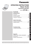
Installation Manual Wireless Touch Control Unit Contents Thank you for purchasing the RF TOUCH wireless control device Please ensure you read and understand both manuals prior to installing and using the RF Touch. The instruction manual is intended to aid installation and use of the equipment. Installation of the product can only be carried out by a qualified electrician and must be wired in accordance with the latest IEE Wiring Regulations. Dependant on the number of devices programmed, the screen may lag slightly especially during programming whilst the RF Touch waits for the return signal from the relevant device. Heating installation is not included in these instructions. We recommend the installer undertakes training prior to commencing with any RF Control heating installation. Trouble free functioning of the RF Touch is dependent on correct storage and handling. If there are any signs of damage, deformation, malfunction or missing parts, do not install this product and please return it to the distributor. Incorrect installation or mishandling of the product may invalidate the warranty. Standard warranty is 12 months from date of purchase. • Control numerous devices via the touch screen • Control and dim lighting • Switching of electrical loads and equipment • Blinds / shutters / curtains etc. • A combination of detectors • 'Holiday Mode' settings for switching, dimming and blind actuators • Create scenes/moods to control multiple devices from a single touch of the screen • Visualise the status (ON/OFF etc.) of all devices on the system • Communicate wirelessly with devices, eliminating the need for cabling to a central point Previous Display.....................................................................................24 Alter Settings...........................................................................24 Mode.......................................................................................24 Change Password...................................................................25 Reset Device...........................................................................25 Block Keyboard.......................................................................26 View Of Menu..........................................................................26 Main Screen............................................................................27 On Screen Warnings...............................................................28 Notes.......................................................................................30 Before you start RF Touch allows you to: 2 Additional Settings Contents Contents Overview of RF Control Devices...............................................4 Characteristics..........................................................................6 Technical Specification..............................................................7 Positioning.................................................................................8 Power Supply Options...............................................................9 Overview Of Screen Icons.......................................................10 Completing The Installation Form...........................................11 Initial Setup Calibration Of The Screen.................................................12 The Home Screen.............................................................12 Settings Settings Menu.........................................................................13 Menu Create (Location / Circuit Names) Add....................................................................................14 Edit....................................................................................15 Remove.............................................................................15 Programming Of Actuators Actuator Types..................................................................16 Add And Assign..........................................................17 Remove.......................................................................18 Change An Address...................................................19 Synchronisation..........................................................19 Communication Test...................................................19 Assign A Detector.............................................................20 Remove.......................................................................21 Pair With......................................................................21 Paired With..................................................................21 Quick Control Assign.........................................................................22 Remove.......................................................................23 Change Of Address....................................................23 Change Setting...........................................................23 Forward 3 Overview Of Wireless RF Control Devices Overview Of Wireless RF Control Devices All actuators in the RF Control System can be controlled by one RF Touch central unit and all transmitters of the system simultaneously. Switching Actuators RFSA-61B 16A 230V~ single channel multifunction switching actuator 6 functions RFSA-61M 16A 230V~ single channel multifunction switching actuator 6 functions Blind / Shutter Actuators RFSAI-61B 16A 230V~ single channel multifunction switching actuator with 3V DC switch input 6 functions RFSA-66M 6 x 8A 230V~ six channel multifunction switching actuator. 6 functions on each channel RFSA-62B RFJA-12B/230V 2 x 8A 230V~ two channel multifunction switching actuator 6 functions on each channel 8A 230V AC switching relay actuator RFJA-12B/24V DC 12-24V DC contactless switching actuator RFSC-61 13A 230V~ multifunction plug-in switching actuator 6 functions Detectors JA-82M Wireless window / door contact (UPVC frames) 2 x CR2354 3V batteries JA-83M Wireless window / door contact 1 x CR123A 3V battery JA-83P Wireless PIR sensor 1 x CR123A 3V battery Dimming Actuators RFDA-71B 250Va 230V~ multifunction dimming actuator (de-rate for LED loads) 7 functions RFDEL-71B 160Va 230V~ multifunction dimming actuator with load selection, trim function and switch input 7 functions RFDAC-71B Actuator with analogue output 0(1)-10V 1 x 16A 230V AC switching contact 7 functions Control of 1-10V dimmable ballasts and other 0-10V devices. 4 Previous Contents Contents Forward 5 Characteristics Technical Specification Technical Parameters Display The RF Touch central control unit provides intelligent control It can be used for: • Central control of all units from one place • Complete overview (visualization) of the current status of units (appliances / equipment) Features: • Can control switching, dimming and shutter actuators 3:4 52.5 x 70 mm Operating Conditions Backlight: Active (white LED) Operating temperature: 0 ... +55°C Touch screen: Resistive 4-wire Storage temperature: - 20 ... +70°C Display: 3.5” Protection: IP 20 Touch sensitive Over voltage category: III Pollution degree: 2 Operating position: Arbitrary Installation: Surface Mounted Dimensions: Weight: 94 x 94 x 24 mm • Programmable for simulated occupancy with holiday mode Terminated in to the back 100 - 230 V AC From the side 12 DC * Power consumption: Max. 5 W Power supply connector: A1 - A2 Control • 40 actuators and 30 detectors can be assigned to each RF Touch unit The RF Touch unit can only be combined with RF Control units marked as RF Touch compatible. Previous Contents Max. 2.5 mm2 / 1.5 mm2 with socket Visible area: Voltage / specific current: • 3.5 inch colour touch screen (no mechanical buttons) Max. cross section of wires: Aspect ratio: Power Supply • RF Touch is surface mounted with 100-230V power supply wired directly in to the back or from the 12V DC plug in transformer (supplied) Screwless terminal push-in or 12V DC jack 2.1 mm Colour TFT LSD 320 x 240 pixels / 262,144 colours Control: RF Touch Compatible Connection: Type: Resolution: • Displays feedback from detectors Design: 6 Technical Parameters Range up to: Minimal range RF Touch – actuator: 100 M 1 metre Frequency: 868.5 MHz Contents Standards: 175 g EN 60669, EN 300 220, EN 301 489, RTTE Directive, NVNo.426/2000Sb (Directive 1999/ES) Forward 7 Positioning Of The Rf Touch And Rf Devices Power Supply And Wiring Requirements Please note: The radio signal range of the RF installation depends on the building construction, materials and position of all devices. Before final fixing the RF Touch we suggest that a communication test is performed to each actuator from the RF Touch when it is in the proposed installation location (See menu create and programming sections) Direct 230V Termination Power Supply Adapter Transmission of radio-frequency signals through various materials Wooden structures with plasterboard 80-95 % Brick wall 60-90 % Reinforced concrete 20-60 % 12V DC plug-in adapter (supplied) Fitting Metal plates 0-10 % 230V Supply A1 - Live (Brown) A2 - Neutral (Blue) (The centre termination is not required) Standard glass 80-90 % Double Insulated Ensure the electrical circuit is isolated prior to starting any electrical installation. Any electrical installation must be undertaken by a qualified electrician in accordance with the latest IEE Wiring Regulations. 8 Previous Contents Contents Forward 9 Overview Of Screen Icons Basic Completing The Installation Form Main menu Dimming 7 Day Timings Switch on Settings Dimming Holiday Mode Switch off • Location of each unit (to create a menu) i.e. lounge / front bedroom etc. and the circuit it controls (20 characters max.) Back to the home screen Blinds Dimming • Device function, i.e. switching / heating / dimming etc. Step back one screen Detectors Dim up time • Each unit's product reference (e.g. RFSA-61B, for the correct classification of the group) Scroll up Scroll down Quick control Keyboard . Dot Confirm abc Letters Yes/selected A/a Small/capital letters No/not selected _ Space a/1 Switch - letters / numbers Edit/remove OK Confirm C Switching Switch on Dim down time Switch off Impulse Button OK Confirm Blinds Time function - delayed switch on - delayed switch off • Address of each unit (to identify the actuator, for example: 00102F) Completing the form will aid programming of the RF Touch and will help with any future maintenance or additions to the system. We also recommend noting details of the quick controls with noting light levels when dimmed and time settings where applicable. The installation form is supplied with this manual or can be downloaded from www.clickinels.com. Product reference E.g. RFSA-61B Lower blinds t+2s Measured time +2s Erase previous Delete Previous Complete the form as follows: Raise blinds Detectors Searching detector(s) Add Name/address of the actuator(s) 10 Installation Form Switching Setup Menu OK Holiday Mode RF Touch version Information and number of assigned units Contents Address E.g. 00102F Example of form information required: No. Location/Circuit (20 chars) Device Function Actuator Part No. Actuator Address 1. Porch Light Switching RFSA-61B 00102F 2. Lounge Wall Lights Dimming RFDA-71B 00AB34 3. Lounge Table Lamp Switching RFSC-61 004D14 Contents Forward 11 Initial Setup Settings - Language, Date & Time Calibration Fig. 1 The 'Settings' menu can be accessed by pressing in the top right corner of the screen (Fig. 7). The password screen (Fig. 8) then appears. Enter the default password '1111' and press 'OK' to fully access the 'Settings' menu (Fig. 9). Note: The password can be changed to help prevent access to the settings menu, see page 25 for more information. When the RF Touch is switched on for the first time the 'display calibration' screen will appear automatically. The touch screen is controlled by lightly touching the desired location. On the screen (Fig. 1) appears a cross starting in the top left corner, cleanly press on the cross twice, repeat for the remaining three corners when the cross is shown. The RF Touch is now calibrated. Note: In the event the screen does not calibrate correctly, turn off the power and then back on. When the 'RF TOUCH' logo appears, press and hold the screen until the calibration screen appears. Calibrate as above. Fig. 10 Fig. 9 Setting Menu Content Of The Home Screen The 'Settings' menu contains two screens. Press the move between the screens (Fig. 9 & 10). • Date and day • Time (touching on the time in the top right corner of the display will switch between analogue and digital clocks (Fig. 2 & 3) • Either the 7 day icon or holiday mode icon may be displayed if preferred. See page 24 • The three boxes along the bottom can be customised to show favourite functions, e.g.: lighting, scene etc. (Fig. 4). See page 27 • Touch the main clock area to enter the Main menu (Fig. 5 & 6) Fig. 2 Fig. 3 Fig. 4 Language Fig. 5 Fig. 6 Select language (Fig. 9) Select the preferred language - (Fig. 11) . Press OK to save. Fig. 11 Date & Time Previous Contents Contents Fig. 12 buttons to Fig. 13 Select Date and time (Fig. 9) • Date and Time • Automatic transition between winter & summer time (Time Zone GTM +01:00) • Format settings hours (12h / 24h mode) Press 12 Fig. 8 Fig. 7 Main Menu / Settings OK to save. Forward 13 Settings - Menu Create Settings - Menu Create Using the information in the completed installation form, programme the individual location/circuit names in to the RF Touch menu. Menu (create menu) Menu (create menu) is used to add, edit or remove the location and circuit names of the individual devices on to the system. In this menu (Fig. 1) you need to first create your own device location labels for the sections you want to control. Creating names is important for successful programming of the RF Touch. Quick Control names should describe the mood / scene to be created e.g. 'TV' or 'Reading'. Each actuator must have its own location /circuit identification, e.g. if there is more than one blind actuator in one location (room), then you must ensure you can easily identify each one, e.g. Kitchen Blind 1 / Kitchen Blind 2 etc. Menu (create name) - Edit Menu (create name) - Remove The Edit button is used to modify an existing name in the menu listing. The Remove button can be used to delete an existing created name in the menu listing. Press the Remove icon (Fig. 10) the device function menu appears, select the function in which you want to remove the name (Fig. 11). Select the device label you want to delete by touching it. (Fig. 12). to confirm the selection (Fig. 13). WARNING - This Press will also delete any assigned actuator! Press the Edit icon (Fig. 6), the section menu appears, select the device function in which you want to edit the created name (Fig. 7). Select the name to be edited (Fig. 8) and then edit with the displayed keyboard. Press OK to save (Fig. 9). Menu (create menu) - Add Fig. 6 Press the Fig. 10 Add icon (Fig. 2) to show a list of sections (Fig. 3): Switching Dimming Blinds Detectors Quick Control Fig. 7 Choose the section where you want to add the location / circuit name and type your own text using the keyboard on the screen (max. 20 characters). Example 1: If you want to setup blind actuators - Select the 'Blinds' section by tapping on the text 'Blinds' (Fig. 3) and the 'Add next'. Complete for every actuator on the system within the relevant sections e.g. switching actuators, dimming actuators etc. Fig. 1 14 Fig. 2 Previous Fig. 3 Fig. 4 Fig. 8 Fig. 12 Fig. 9 Fig. 5 Contents Fig. 11 Contents Fig. 13 Forward 15 Settings - Programming Settings - Programming Programming - Add, Assign Or Remove Add And Assign An Actuator To A Location / Circuit Name Programming is used to add, assign or remove the actuators / detectors to the location / circuit names created in the previous section. The Programming menu can be accessed from the Main Menu by pressing in the top right corner (Fig. 1). Select Programming (Fig. 2) and then enter the password (default - 1111) (Fig. 3). The assigning of actuators is divided into sections based on the functionality. Depending on the actuator's type you have to select the appropriate programming section - see Fig. 4 and table below (e.g. Actuator RFSA-61B - will be found in the Switching section). This enables you to add the address of an actuator and then assign it to a location / circuit name. In the required section (switching, dimming ...) select Assign new (Fig. 5). A list of relevant actuator types will be shown. (Fig. 6). Select the name of the actuator which you want to associate with the location / circuit. Enter the address* of the actuator you want to assign (Fig. 7) as printed on the actuator. From the menu structure created earlier, select the location / circuit name to which the actuator will be assigned (Fig. 8). • Only one actuator can be assigned to each location / circuit. • When programming, ideally the actuator must be installed and powered to allow the signal to be tested. • Communication test (Fig. 10) is used to test the current status of the RF signal between the RF Touch and programmed actuator. • Press Start (Fig. 11) to initiate the test, the current status of the signal is displayed. RF Control Actuator Types Switching Dimming Blinds Detectors RFSA-6x * RFDA-71B RFJA-12B/230V JA-81M RFSAI-61B RFDAC-71B RFJA-12B/24V DC JA-82M RFSC-61 RFDEL-71B • Press Close to get back to the programming menu. *6 digit hexadecimal address recorded on the installation form (see page 11). Fig. 5 Fig. 6 Fig. 7 Fig. 8 Fig. 9 JA-83P RFDAC-71B * RFSA-61B, RFSA-62B,RFSA-61M and RFSA-66M actuators Fig. 2 Fig. 1 16 Previous Fig. 3 Fig. 10 Fig. 4 Contents Contents Fig. 11 Forward 17 Settings - Programming Settings - Programming Remove An Actuator Change Address, Synchronisation And Communication Test When required, it is possible to remove a programmed actuator from the location / circuit name. Select the required section (Fig. 1), select Assigned receivers (Fig. 2), select the required location / circuit name from the list (Fig. 3). The assigned actuator is shown (Fig. 4). By pressing you can check the address assigned to the actuator (Fig. 5). By pressing the product reference or address of the actuator (Fig. 6) you can then select to either 'Remove', 'Change of address', 'Synchronisation' or 'Communication test' the actuator (Fig. 7). Remove the actuator by pressing 'Yes' (Fig. 8). If required, it is possible to change the address from the original programmed actuator to one with the same functionality (Fig. 9 & 10). The 'Synchronisation' facility (Fig. 11) is only available on switching, dimming and blind actuators. The facility is required (Fig. 12) ( )for where an actuator is programmed in to more than one RF Touch on the same installation, allowing synchronisation of the actuator status on all RF Touch units. (Fig. 13) Note: If only a single RF Touch is installed the 'Activation' button can be left as Communication test (Fig. 14) is used to test the current status of the RF signal between the RF Touch and programmed actuator. Press Start (Fig. 15) to initiate the test, the current status of the signal is displayed. Fig. 4 Fig. 1 Press Close to get back to the programming menu. Fig. 6 Fig. 9 Fig. 11 Fig. 12 Fig. 14 Fig. 2 Fig. 7 Fig. 3 18 Previous Fig. 5 Fig. 8 Contents Fig. 10 Contents Fig. 13 Fig. 15 Forward 19 Settings - Programming Settings - Programming Detectors - Assign Selecting 'Detectors' within Programming (Fig. 1) enables the assigning or removal of the window, door and PIR detectors to the menu. Select Assign detector (Fig. 2). The list of detectors will be shown (Fig. 3). Select JA-81M / 82M (for JA-83P select JA-81P) (Fig. 4). The RF Touch will start searching for devices (Fig. 5) (the shortest distance to assign a detector is 1.5M). Do not insert the batteries in to the detector until the RF Touch starts to search! Insert the batteries in to the detector and it will be recognised once it has transmitted its address. Confirm the assignment by pressing (Fig. 6). Choose the location / circuit name to which the detector is to be assigned (Fig. 7). Each detector may be assigned to one location. Pressing arrows will display the address associated with the detector (Fig. 8 & 9). When you touch on the location or address of the detector the following options appear (Fig. 10): Remove… Fig. 1 Fig. 11 Remove Pair with ... Fig. 3 Fig. 7 Note: The two state JA-82M can be used in two ways: • Information about the status (open / close) - e.g, window is open (without pairing with a switching actuator) •P airing with the multifunction switching actuator, which responds to the detector status (open / close) - e.g. light is switched on when you open the door. Fig. 12 Pair with... Fig. 13 The detector can be paired with multifunction switching actuators from the switching menu, (e.g. detector with hall light, Fig. 12 & 13). One detector can be paired with up to 30 multifunction switching actuators. If the detector is paired with a switching actuator the function 'delayed off' is automatically activated. When the detector is activated, the assigned actuator switches the connected device for the programmed time (2s - 60min). Time delay can be set in the Control Menu of the paired switching actuators under 'Next Functions' and 'Setting Time'.. The above method can be used to assign additional detectors. Paired with ... Fig. 5 Removes the detector from its assigned location label within the 'Detectors' menu. To confirm (Fig. 11). Fig. 9 Fig. 14 Fig. 2 Fig. 4 Fig. 6 Fig. 8 Fig. 10 The RF Touch can be programmed with up to 30 detectors. Fig. 15 Note: The minimum distance between the detector and RF Touch is 1.5 meters. Paired with... This menu lists the switching actuators which are paired with the detector. By touching the name you can remove the paired actuator if required (Fig. 14 & 15). 20 Previous Contents Contents Forward 21 Settings - Programming Settings - Programming Quick Control - Assign Actuators Remove, Change Of Address And Change Setting Quick control is used to link / group commands together to form a complex scene or mood that can be operated from a single touch screen button. For each scene or mood you can assign a combination of up to 20 different actuators. Note: Quick control names need to be created within the menu (create menu) function prior to assigning devices. See page 14. Note: Quick control elements can only be created when all of the actuators have been programmed and assigned in the different sections, e.g. switching, dimming etc. Within 'Programming' select 'Quick control' (Fig. 1), select the scene name (Fig. 2). Within 'Programming' select 'Quick control' (Fig. 1), select the scene name (Fig. 2) and then 'Assigned receivers' (Fig. 7). Select the location / circuit name (Fig. 8) to then display the options, 'Remove', 'Change of Address' and 'Setting'. The 'Remove' (Fig. 9 & 10) facility removes the location / circuit association from the scene's group command list. However the location / circuit name and the assigned actuator will still remain as previously defined. If required, it is possible to change the address from the original programmed actuator to one with the same functionality (Fig. 11). The assigned location / circuit, the previously defined setting can be changed under 'Setting', e.g. if previously set to 'Delay ON' you could change it to 'ON' without the delay (Fig. 12). Select Assign new (Fig. 3) it will display the functionality list (Switching, Dimming and Blinds). Select the function type you want to assign (Fig. 4). Select the location / circuit name (Fig. 5) and then define what you would like the actuator to do for this one scene (ON/OFF/DIM etc.)(Fig. 6). The screen will then return to the functionality list (Fig. 4), where you can continue adding elements to the scene. To assign receivers to another Quick Control scene, press Fig. 1 22 Fig. 2 Previous Fig. 3 twice to get back to the list of scenes / moods previously created. Fig. 4 Fig. 5 Fig. 7 Fig. 6 Contents Fig. 8 Fig. 9 Fig. 11 Fig. 12 Fig. 10 Contents Forward 23 Settings - Display And Mode Settings - Change Password And Reset Device Fig. 1 Display - Alter Settings Change Password Screen: Change the colour of the screen background (black, blue, green, purple). Screensaver: The screen will change to the selected brightness (25%, 50%, 75%, 100%) after the selected time (15s, 30s, 1 min, 3 min) since it was last touched. Fig. 2 Sleep mode: Select the time (0 min, 10 min, 15 min, 20 min) period before the unit goes to sleep (the screen goes off. Touching the screen wakes the unit up). '0 min' the screen stays on. Gives the facility to change the default '1111' password to help prevent unauthorised access to the programming menu. Enter the default password (1111) (Fig. 11) the new password screen will appear - type in your new password and confirm. Press OK to save (Fig. 12). Note: Please ensure the new password is documented for future reference. If the changed password is lost the RF Touch will need to be returned to the manufacturer for unlocking. Fig. 9 Fig. 10 Fig. 11 Fig. 12 Calibrating the display: A cross will appear in each corner of the screen one at a time, which needs to be touched twice. Calibration is then complete. (Re-sizes the touch area of the device to the maximum allowable screen area). CAUTION: If you touch the screen elsewhere e.g. inside the position of the crosses, it is possible to reduce the touch sensitive area size to one that will not function correctly. Mode Gives the option to enable (Fig. 4, 5 & 6) or disable (Fig. 7 & 8) the holiday mode facility on the home screen for switching, dimming and blind actuators. For more information on setting the times for holiday mode, see the user manual. Fig. 3 24 Fig. 4 Previous Fig. 5 Fig. 6 Fig. 7 Reset Device To reset the device to factory defaults enter '1234' (Fig. 14). This password cannot be changed. Confirming the reset (Fig. 15) will return the RF Touch unit to out of the box factory settings, removing all information previously programmed and also force a screen calibration. Fig. 8 Contents Fig. 13 Contents Fig. 14 Fig. 15 Forward 25 Settings - Block Keyboard And View Of Menu Settings - Main Screen Block Keyboard Main Screen Helps prevent accidental or unwanted control of the RF Touch (Fig. 2). After activation (Fig. 3), the unit will go in to lock mode after 10 seconds (Fig. 4). To unlock press the lock icon twice (Fig. 5). Fig. 1 Fig. 4 Fig. 3 Fig. 2 Enables personalization of the three sections of the display banner at the bottom of the Home Screen (Fig. 9 & 10). Left (1st choice), middle (2nd choice) and right (3rd choice) can be used to set the most common controlled devices or scenes directly from the home screen banner as short links. Fig. 5 Fig. 9 Fig. 10 Fig. 11 View Of Menu The Main Menu list can be set so only those sections that you want to see are shown. (e.g. only Dimming, Switching and Detectors (Fig. 6 & 7). If all sections are de-selected with , you will only see the list of location / circuit names of the actuators without its function (Fig. 8), this view is useful only if up to 6 actuators are programmed. Fig. 6 26 Previous Fig. 7 Fig. 8 Contents Contents Forward 27 RF Touch Unit Warnings RF Touch Unit Warnings Warning is displayed in case of incorrect or incomplete entry. Warning is displayed in case of incorrect or incomplete entry. Warning 28 Procedure Warning Procedure Up to 40 rooms may be defined. No more than 40 device names may be entered All 5 programmes are engaged. No other programme can be entered Saving failed. Repeat entry No unit allocated to the room. Allocate actuator Delete failed. Repeat entry This group has already been allocated. Enter new settings No unit allocated. Allocate (assign) the requested actuator Display incomplete - control impossible. Two time programmes overlap within a single day. Check time settings and enter new settings ensuring they do not overlap No time programme available within a single day. No other programme can be entered Calibrate the device (disconnect the power supply, after reconnecting hold the logo RF Touch, finish the calibration by touching twice the cross signs that appear in each corner of the screen) No day selected. Select the required day and enter new time settings EPROM memory error! Contact the manufacturer Switch on time may not exceed the switch off time. Enter new settings RTC circuit error! Contact the manufacturer Unit already allocated to the room. Select another room. Only one actuator can be allocated to one name of device (outside Quick Control) AT45 circuit error! Contact the manufacturer This room has already been defined in the group. Enter a new name Have you lost the password? Please ask the manufacturer for information about further steps The address has already been selected in the unit list. Choose another address. Enter correct address information Battery icon appears on the main screen See page 19 The address information must be complete. Enter correct information Up to 40 units may be defined. No more than 40 units may be entered The switch on date must be different from the switch off date. Enter new settings The switch on date must not exceed the switch off date. Enter new settings Previous General Information With consideration to the transmission of the RF signal, ensure that RF components are suitably located in the building where the device is to be installed. The RF Control system must only be installed in indoor areas. The device has not been designed for outdoor use or use in moist environment, it must not be installed in metal distribution boxes and plastic distribution boxes with metal doors as this would prevent the transmission of the radio frequency signal. RF Control is not recommended for the control of devices providing vital life functions or for the control of at risk devices such as pumps, electrical heaters without heat regulators, lifts, pulleys etc. - radio frequency transmission could be hampered with an obstacle, interfered with, the transmitter battery may become depleted etc. thus disabling the remote control. Not suitable for use in an industrial environment. Do not expose to extreme temperature changes. In case of extreme temperature changes allow approx. 2 hours prior to installation for the RF Touch to adjust to the temperature of the installation location. This will prevent condensation of moisture in the device and the occurrence of a potential short circuit. Keep flammable materials away from the device. The graphic indication of the contact / device status (red/green LED) is only for information and may be influenced by the amount of processed information or the combination of more RF Touch and RF Pilot control units. Contents Contents Forward 29 Notes 30 Notes Previous Contents Contents Forward 31 www.clickinels.com Scolmore Park, Landsberg, Lichfield Road Industrial Estate, Tamworth, Staffordshire B79 7XB Tel.: 01827 63454 Fax: 01827 63362 [email protected] www.scolmore.com Previous 18 Corrig Road, Sandyford Industrial Estate, Dublin 18, Ireland Tel.: +353 (1) 2811 122 Fax: +353 (1) 2811 224 [email protected] www.clicklitehouse.ie V2.20 Contents