1
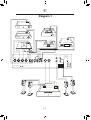
ECI 5 MKII
Balanced Integrated Amplifier
Owner's Manual
EN
N
Unpacking the ECI 5
Immediately upon receipt of the ECI 5 MKII , inspect the carton for possible damage during shipment.
The carton and packaging have been designed to provide the safest
possible protection for transport of your integrated amplifier. Unpack the
unit carefully. Save all packaging materials for future shipment.
The contents of the carton
•
•
•
•
•
•
1
1
1
1
1
2
pcs
pcs
pcs
pcs
pcs
pcs
Electrocompaniet ECI 5 MKII integrated amplifier.
AC main cord.
spare main fuse (located in the fuse drawer).
inspection card.
remote control.
batteries.
Set up procedure
Before connecting the ECI 5 MKII to the mains, check that the main voltage indicated on the rear panel corresponds to the line voltage in the
territory were you intend to use the unit.
How to avoid damages
Do not under any circumstances connect or disconnect equipment when
power is turned on.The design of the RCA plug generates a huge transient when inserted. Connecting or disconnecting equipment with the
power on can result in severe damage to both speakers and amplifier.
How to avoid noise problems
The ECI 5 MKII contains delicate circuits that are sensitive to magnetic
strayfields. The unit should not be placed near mains transformers, TV
sets etc. Care should also be taken regarding placement of the interconnect cables. Do not run interconnect cables in parallel with maincords or
speaker cables. Keep interconnect cables as short as possible.
How to avoid possible antenna problems
In some set-ups hum may occur when you connect the radio, VCR or TV
to your system.The problem is caused by DC voltage coming from your
antenna. Please contact your cable network operator.
How to connect your system
Please read this page carefully and follow diagram 1, page 14.
2
ENG
Balanced XLR input and operation:
The balanced mode can only be used if the signal source has a balanced output. Use anXLR interconnect with GND on pin 1, + on pin2,
and - on pin 3. To use the balanced input single ended, connect the
ECP5XLR in the XLR
Single ended RCA input and operation:
The left channel is the top row on the rear, marked black. All inputs are
similar regarding sonic performance. Unused inputs may be shorted to
ground, using a RCA shorting plug.
HT (Home Theatre)
Is a direct input where the volume potentiometer is bypassed. ECI 5
MKII will work like a poweramplifier with fixed gain. When selected the
output will be muted for a few seconds as a safety against accidental
overload.
REC outputs are used for recording.
The source you listen to will be monitored through this output. The record
output is not influenced by the volume control setting, but will be shut off
by the MUTE function. Never use shorting plugs in outputs.
Pre out:
The pre out is dependent by the volume control setting, and MUTE function. These outputs (balanced and single ended) can be used to control
an additional power amplifier. If more than one amplifier is used, and
these amplifiers are DC coupled on the input side, they will influence on
each other when the amplifiers are switched on/off. To avoid any problem, these amplifiers must be turned on/off simultaneously. Never use
shorting plugs on the outputs.
Speaker output:
Never short the positive output to ground or chassis.Switch the amplifier
off when connecting the speakers.
How to power up your system
You should always power up your system the following way:
Signal sources (CD player, tuner etc.) first.
Allow a 30 seconds warm-up before you turn on the ECI 5 MKII.
When switching off your system:
Start with the ECI 5 MKII, then the signal sources.
3
ENG
Remote control
1.
2.
3.
4.
(Diagram 2, page 15)
Input selector CD, TUNER, TAPE, DVD, VCR, HT
Mute on / off (Press for 1-2 sec. to set into Stdby)
Volume up
Volume down
Front panel
(Diagram 3, page 15)
The main switch is located in the center of the lower part of the front
panel. In daily operation, switch off the ECI 5 MKII by using the MUTE
button on the remote control. If the ECI 5 MKII has been switched off,
allow two hours of warm-up for optimal sonic performance. When the
ECI 5 MKII is not to be used for a long period of time, use the main
switch to turn the unit off. Then disconnect the AC main cord for maximum safety.
Navigator window (Diagram 3, page 15)
The six inputs is avaliable:
TAPE, TUNER, CD, HT, VCR, DVD
In case of operating errors the display will inform of the fault status.
The following faults may occur:
-
Temperature fault - Internal temperature limit exceeded.
DC fault Right - DC voltage on right output.
DC fault Left - DC voltage on left output
Overload Left - Output overload left channel
Overload Right - Output overload right channel
To reset any fault turn off the main power switch and then power up
again as normal.
4
ENG
Replacing a blown main fuse
(Diagram 5, page 15)
The main fuse is located in a small drawer inside the AC inlet of the unit.
If, for some reason the fuse is blown, turn the unit off, and remove the
AC cord from the AC inlet. Open the drawer with a small screwdriver
and remove the blown fuse. The spare fuse is located inside a holder in
front of the main fuse.
1. Remove the spare fuse gently by pushing it sideways out of its holder.
2. Insert the spare fuse as the active fuse.
3. Push the drawer gently back to closed position.
4. Re-insert the AC cord and turn the unit on.
Never replace the fuse with other values than indicated on the unit!
Replacing remote control batteries
(Diagram 4, page 15)
To replace the battery, lift the cover off, and insert a fresh set of batteries. Be careful to follow the + and - polarity indications at the bottom of
the battery compartment.
Battery type: 2 x LR03 / AAA: 1.5Volts
Input configurations
(Diagram 6, page 15)
XLR input: 1 = ground 2 = positive 3 = negative
RCA: Center = positive Circle = ground.
Output configurations
(Diagram 6, 15 and 1, pg 14)
XLR output: 1 = ground 2 = positive 3 = negative
Speaker: Red = positive Black or White = ground
ECP5XLR:
RCA to XLR adapter: 1 & 3; ground and negative = shorted 2 = positive
5
ENG
Technical specifications ECI 5 MKII:
The following technical data where measured on randomized test objects
and are typical data. All measurements are made at 120V / 240V //
50Hz / 60Hz Clipping point of the amplifier is set to a level where total
harmonic distortion (THD) is 0.2 %.
Preamplifier section
Input impedance(Balanced input)................................... 47 kOhm
Maximum input level .................................................... 10 Vrms
Noise floor (1Vrms, 20 - 20 kHz, balanced).................... -135 dB
THD + N (1Vrms, 20 - 20 kHz, balanced) ...................... <0.003%
Gain (Balanced)............................................................ 0 dB
Amplifier section
Output Impedance ........................................................< 0,02 Ohm
Frequency response (- 3 dB)............................................1 – 150 kHz
Channel separation........................................................> 120 dB
THD + N (20 - 20 kHz).................................................< 0.004%
Maximum peak current...................................................>100A
Damping factor (8 ohm load)..........................................>350
Input sensitivity (120W output)......................................1.3Vrms
Input sensitivity HT (120W output)...................................1Vrms
Rated output power
10 % change in line voltage will give approximately 20 % change in
output power.
8 Ohm2 x 120 W
4 Ohm2 x 200 W
2 Ohm2 x 370 W
Power consumption (no load or signal) 100 W
Standby - 1W
The ECI 5 MKII is DC coupled from input to output.
Dimensions
Width: 483 mm - 19 inch
Depth: 405 mm - 16 inch
Height: 135 mm - 5,3inch
Weight: 20 Kg - 44 lbs
Specifications are subject to change without further notice.
6
ENG
Important Notice
For optimal sonic performance, the ECI 5 MKII should be burned in for
a minimum time of 72 hours. The easiest way to burn in your ECI 5 MKII
is to put a signal at any input, without the speakers connected In daily
operation, switch off the ECI 5 MKII by using the MUTE button on the
remote control. If the ECI 5 MKII has been switched off, allow two hours
of warm-up to optimal sonic performance. Due to high class A operation
in all Electrocompaniet designs, it is normal for the ECI 5 MKII to feel
warm. Proper ventilation is important. It is important that there is at least
3-5 cm (1-2inches) of air on the left side of the amplifier and 5-8 cm (2-3
inches) above. Never cover the ventilation area.
If Service is needed
Your dealer will have all relevant information regarding the service centers in your area, and will ensure that your unit is serviced with minimum
delay. It is our general policy to have your unit returned to you within
five working days. This is an average time, and can vary locally,
depending on the workload at that particular service station. If, for some
reason, there are no service facilities available in your country, please
ship the unit to the following address:
Electrocompaniet as,
Breivikveien 7,
N-4120 Tau,
Norway
Web: www.electrocompaniet.com
Service department: [email protected]
The end user is responsible for all shipping charges, insurance, re-importation and duty charges. When shipping a product to the factory for
service, always include the following:
1. A sales slip or other proof of purchase if repair is claimed under warranty.
2. A proforma invoice with value of goods, stating that the amplifier is
returned to Norway for repair.
3. An accompanying letter describing faults, symptoms, or problems with
the unit.
4. Always ship the unit in its original carton and packaging material to
prevent damage in transit.
Electrocompaniet will not cover damages incurred in transit. If you
require further information concerning the operation of the unit, or if you
have any questions related to service, please do not hesitate to contact
your dealer or your national distributor.
7
N
Pakke ut ECI 5 MKII
Etter du har mottatt ECI 5 MKII bør du inspisere esken for skader som
kan ha oppstått under transport. Innpakningen er laget for best mulig å
unngå skader på produktet under transport. Pakk ut apparatet forsiktig.
Spar på innpakningen for senere bruk.
Eskens innhold
•
•
•
•
•
•
1
1
1
1
1
2
stk
stk
stk
stk
stk
stk
Electrocompaniet ECI 5 MKII integrert forsterker
Nettledning
Reservesikring (ligger i sikringsskuffen bak på apparatet.)
Inspeksjonskort
Fjernkontroll
Batterier
Før du kobler til
Før du kobler apparatet til nettet bør du sjekke at nettspenningen i området du befinner deg i stemmer overens med spenningen som er markert
bak på ECI 5 MKII.
Hvordan unngå skader
Du bør ikke under noen omstendigheter koble til eller - fra kabler eller
utstyr mens ECI 5 MKII er påslått. Utformingen av RCA kontakten forårsaker en stor transient når den kobles til. Til eller frakobling av utstyr når
ECI 5 MKII står på, kan forårsake skader på både ECI 5 MKII og høyttalere.
Hvordan unngå støy
ECI 5 har elektronikk som er følsom for magnetfelt, så apparatet bør ikke
plasseres i nærheten av transformatorer og tv apparater. Ta også hensyn
til hvor du legger signalkablene. Disse bør ikke ligge parallelt med nettkabler og høyttalerkabler. Du bør også holde signalkablene så korte som
mulig.
Hvordan unngå mulige antenneproblemer
I noen tilfeller kan det oppstå brum når du kobler forsterkeren til tv eller
video. Dette kan være forårsaket av en DC - spenning som kommer fra
antennekabelen. Kontakt din kabelleverandør for løsning av dette problemet.
Hvordan koble opp ECI 5 MKII
Les og følg diagram 1 side 14
8
N
Balansert XLR
Du kan bare benytte balansert oppkobling dersom du har en signalkilde
med balanserte utganger. Bruk en signalkabel med jord på pinne 1,
pluss på pinne 2 og minus på pinne 3.Om du skal bruke den balanserte
inngangen med en ubalansert kilde, må du koble i mellom en overgangsplugg (ECP5XLR).
Ubalansert innganger
Øverste rad med RCA-kontakter merket med svart er innganger for venstre kanal. Alle innganger har lik lyd og nivå egenskaper. Ubrukte innganger kan kortsluttes med en kortslutningsplugg.
HT (Home Theatre)
HT er en direkteinngang hvor volumkontrollen er koblet bort. ECI 5 MKII
vil virke som en effektforsterker. Når HT velges vil utgangen være dempet noen sekunder, for å unngå overlast av høyttalere tilkoblet ved eventuell feiltilkobling på HT- inngangen.
REC - utganger
REC utgangene brukes ved opptak. Utgangene vil alltid ha samme signal
som kilden du lytter til. Volumkontrollen har ingen innvirkning på disse
utgangene, men utgangene vil bli koblet fra ved bruk av Mutefunksjonen.
Bruk aldrig kortslutningsplugger i noen av utgangene.
Pre out
Utgangene er påvirket av volumkontrollen og Mutefunksjonen. Disse
utganene (balansert og ubalansert) kan brukes for tilkobling av ekstern
effektforstarker. ECI 5 MKII fungerer da som en forforsterker. Det er fullt
mulig å ha tilkoblet høyttalere til ECI 5 MKII samtidig som pre out utgangene brukes.
Høyttalerutganger:
Kortslutt aldri den positive utgangen til jord eller chassis. Skru alltid av
forsterkeren når du kobler til / fra høyttalerene.
Hvordan skru på
Du bør alltid skru på i følgende rekefølge. Start med signalkilder (cdspiller, radio etc.) Vent gjerne 30 sekunder før du slår på ECI 5 MKII.
Hvordan skru av:
Start med ECI 5 MKII, deretter signalkildene.
9
N
Fjernkontroll (Diagram 2, page 15)
1.
2.
3.
4.
Inngangsvelger: CD, TUNER, TAPE, DVD, VCR og HT (AUX)
Mute av / på (Hold innetrykket i 1-2 sek. for å sette i standby)
Lydstyrke opp
Lydstyrke ned
Frontpanel
(Diagram 3, page 15)
Hovedstrømbryter finner du i senter av fronten. Ved daglig bruk kan du
skru ECI 5 MKII av ved å bruke mute knappen på fjernkontrollen. Skal
ikke forsterkeren brukes over lengre tid, bør du slå av med hovedbryteren. Fjern gjerne nettledningen for sikkerhets skyld. Om ECI 5 MKII har
vært avslått over lengere tid, kan det ta et par timer før lyden er optimal.
Navigasjonsvindu
(Diagram 3, page 15)
På venstre side av ECI 5 MKII viser den aktive inngangen displayet.
Følgende innganger kan velges:
TAPE, TUNER, CD, HT, VCR, DVD
Oppståt feil under drift vil displayet informere om feilen som har oppstått.
Følgende feil kan oppstå:
-
Temperature fault - Intern temperaturgrense overskredet.
DC fault Right - DC spenning på høyre utgang.
DC fault Left - DC spenning på venstre utgang.
Overload Left - Overlast venstre kanal.
Overload Right - Overlast høyre kanal.
For å tilbakestille alle feil, slå av hovedstrømbryteren og slå på igjen
som normalt.
10
N
Skifte av ødelagt nettsikring (Diagram 5, page 15)
Hovedsikringen finner du i en liten skuff rett under nettinntaket. Om
denne sikringen skulle ryke kan du skru av apparatet og fjerne nettledningen. Åpne skuffen med en liten skrutrekker og fjern den ødelagte
sikringen. Reservesikringen finnes i en liten holder foran den aktive
sikringen. Skyv denne sidelengs ut av holderen. Sett den på plass hvor
du fjernet den aktive sikringen. Lukk skuffen, sett inn nettkabel og skru
på. Bytt aldri sikringen med en annen verdi enn den verdien som står
merket på apparatet.
Bytte av batterier i fjernkontroll (Diagram 4, page 15)
Åpne lokket på undersiden av fjernkontrollen og erstat de brakte batteriene med nye. Vær nøy e med polariteten på batteriene. Du finner en
tegning av hvordan batteriene skal sitte i bunnen av batteriboksen.
Batteri: 2 x LR03 / AAA 1,5V
Inngangskonfigurasjon (Diagram 6, page 15)
XLR input:
RCA input:
1 = jord 2 = positiv
Senter = positiv
3 = negativ
skjerm = jord
Utgangskonfigurasjon
XLR output:
Høyttaler:
1 = jord 2 = positiv
Rød = positiv
3 = negativ
Svart = negativ
ECP5XLR: RCA til XLR adapter 1 og 3 = jord 2 = positiv
11
N
Tekniske spesifikasjoner ECI 5 MKII:
Følgende tester er gjort på tilfeldig utvalgte produkter og er typiske data
for ECI 5. Alle målinger er gjort ved en nettspenning på 120 / 240 V
// 50/60Hz. Klippunktet er satt ved en total harmonisk forvrengning
(THD) på 0.2%.
Forforsterker
Inngangsimpedans(Balansert inngang)............................. 47 kohm
Max inngangsnivå ........................................................10 Volt RMS
Støygulv (1Vrms, 20 - 20 kHz, balansert)........................ --135 dB
THD + N (1Vrms, 20 - 20 kHz, balansert)...................... <0.003%
Forsterkning (Balansert inngang)....................................... 0 dB
Utgangsforsterker
Utgangsimpedans.......................................................... < 0,02 Ohm
Frekvensrespons (- 3 dB).................................................1 – 150 kHz
Kanalseperasjon............................................................> 120 dB
THD + N (20 - 20 kHz)..................................................< 0.004%
Max utgangsstrøm...........................................................>100A
Dempningsfaktor(8 ohm last)............................................>350
Inngangsfølsomhet (120W utgangseffekt)...........................1.3Vrms
Inngangsfølsomhet HT (120W utgangseffekt)......................1Vrms
Utgangseffekt
THD = 0.2%
10 % forandring i nettspenningen kan gi ca 20 % forandring av utgangseffekten.
8 Ohm last 2 x 120 W
4 Ohm last 2 x 200 W
2 Ohm last 2 x 370 W
Effektforbruk (uten last og signal) 100 W
Stdby - 1W
ECI 5 MKII er DC- koblet fra inngang til utgang.
Mål og vekt
Bredde: 483 mm - 19 “
Dybde: 405 mm - 16 ”
Høyde: 135 mm - 5,3 ”
Vekt:
20 Kg - 44 lbs.
Data kan endres uten varsel
12
N
Viktig
For optimal lydgjengivelse bør forsterkeren spilles inn minst 72 timer.
Dette kan gjøres uten å koble til høyttalerene. På grunn av høy klasse A
drift vil ECI 5 MKII bli varm, og det er viktig med god ventilasjon. Det er
viktig at det er minst 3-5 cm med luft på venstre side, og 5-8 cm over.
Aldri tett til kjølerillene på forsterkeren.
Dersom service er nødvendig
Din forhandler vil ha all relevant informasjon om service på din ECI 5
MKII. Vi vil returnere forsterkeren innen fem arbeidsdager fra vi mottar
den. Dette kan variere med arbeidsmengde hos vårt serviceverksted.
Electrocompaniet as,
Breivikveien 7,
N-4120 Tau,
Norway
Web: www.electrocompaniet.com
Service department: [email protected]
Sluttbruker er ansvarlig for alle fraktkostnader, forsikring, re-importering
og tollkostnader.
Når du sender inn ECI 5 MKII til service, husk alltid å sende med :
-Kvittering eller annet bevis på når produktet ble kjøpt om reparasjon
skal skje på garanti.
-Proformafaktura med verdien på forsterkeren som viser at forsterkeren
skal returneres til Norge for reparasjon. (Gjelder ikke apparater som
sendes i Norge.)
-Feilbeskrivelse som forklarer feilsymptomer, problemer og hvordan det
har oppstått.
-Send ECI 5MK2 i original innpakning for å forhindre skader under
transport. Electrocompaniet kan ikke dekke skader som har oppstått under
transport.
Ønsker du mer informasjon om ECI 5 MKII eller har spørsmål angående
service se vår hjemmeside for kontaktinformasjon.
13
Diagram 1
DVD
VCR
TUNER
Home Theatre
Mechanical
Cancellation
System
ELECTROCOMPANIET
RIGHT OUTPUT
PUSH
RIGHT INPUT TUN LEFT INPUT
PUSH
L
L
R
R
TAP
MANUFACTURED BY:
ELECTROCOMPANIET, NORWAY
LEFT OUTPUT
+
PUSH
--
PUSH
+
RIGHT INPUT CD LEFT INPUT
DVD
VCR
HT
REC 1
OUT
RIGHT OUTPUT
LEFT OUTPUT
TYPE : ECI 5 Mk2
AW60FTT Balanced High
14
Performance POWERAMPLIFIER
--
CAUTION:
The removal of the top cover
may cause electric shock.
No user serviceable parts inside.
Refer to authorized service
personnel.
Do not expose to moisture or rain.
Diagram 3
Volume level indicator
2
H
P
Volume
up
Graphical display
Power button
previous
input
next
input
Diagram 4
Volume
down
Diagram 2
PUSH
Diagram 5
2
1
Diagram 6
3
5L
SP
US
US
XLR INPUT
1
2
1
2
3
3
XLR OUTPUT
15
ECP5XLR
Warning!
To avoid risk of fire or electric shock, do not expose this appliance to rain or moisture.
Verify line voltage before use.
Do not remove cover. No user serviceable parts inside.
Refer servicing to qualified service personal.
The warranty is void if the product is tampered with by non-authorised personnel.
Use only authorized Electrocompaniet service center.
Made in Norway
www.electrocompaniet.no
16