1
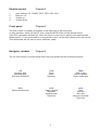
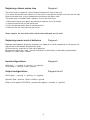
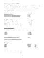
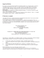
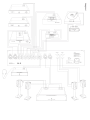
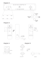
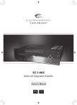
ECI 3
Unpacking the ECI 3
Immediately upon receipt of the ECI 3, inspect the carton for possible damage during shipment.
The carton and packaging have been designed to provide the safest possible protection for
transport of your integrated amplifier.
Unpack the unit carefully. Save all packaging materials for future shipment.
The contents of the carton
1
1
1
1
1
2
pcs Electrocompaniet: ECI 3 integrated amplifier.
pcs AC mains cord.
pcs spare Mains Fuse, (located in the fuse drawer) .
pcs inspection card.
pcs remote control.
pcs batteries.
Set up procedure
Before connecting the ECI 3 to the mains, check that the mains voltage indicated on the rear
panel corresponds to the line voltage in the territory were you intend to use the unit.
How to avoid damages
Do not under any circumstances connect or disconnect equipment when power is turned on.
The design of the RCA plug generates a huge transient when inserted.
Connecting or disconnecting equipment with the power on can result in severe damage to both
speakers and amplifier.
How to avoid noise problems
The ECI 3 contains delicate circuits that are sensitive to magnetic strayfields.
The unit should not be placed near mains transformers, TV sets etc. Care should also be taken
regarding placement of the interconnect cables. Do not run interconnect cables in parallel with
main cords or speaker cables. Keep interconnect cables as short as possible.
How to avoid possible antenna problems
In some set-ups hum may occur when you connect the radio, VCR or TV to your system.
The problem is caused by DC voltage coming from your antenna.
Please contact your cable network operator.
2
How to connect your system
Please read this page carefully and follow diagram 1.
Inputs
Single ended operation:
The left channel is the top row on the rear, marked black.
All inputs are similar regarding sonic performance.
Unused inputs may be shorted to ground, using a RCA shorting plug.
To use the balanced input single ended, connect the ECP5XLR in the XLR
Outputs
REC:
Tape outputs are used for recording.
The source you listen to will be monitored through this output.
The record function is not influenced by the volume control setting, but will be shut off by the
MUTE function.
Never use shorting plugs in outputs.
PRE OUT:
The pre out is dependent by the volume control setting, and MUTE function.
These outputs (balanced and single ended) can be used to control an additional power amplifier.
If more than one amplifier is used, and these amplifiers are DC coupled on the input side, they will
influence on each other when the amplifiers are switched on/off.
To avoid any problem, these amplifiers must be turned on/off simultaneously.
Never use shorting plugs on the outputs.
GAIN SWITCH
On the rear panel you will find a switch to adjust the gain in the amplifier.
Use this switch to accommodate the signal source to the amplifier.
SPEAKER OUTPUT:
Never short the positive output to ground or chassis.
Switch the amplifier off when connecting the speakers.
How to power up your system
You should always power up your system the following way:
Signal sources (CD Player, tuner etc.) first.
Allow a 30 seconds warm-up before you turn on the ECI 3.
When switching off your system:
Start with the ECI 3, then the signal sources.
3
Remote control
1.
2.
3.
4.
Diagram 2
Input selector CD, TUNER, TAPE, DVD, VCR, AUX.
Mute on / off
Volume up
Volume down
Front panel
Diagram 3
The main switch is located in the center of the lower part of the front panel.
In daily operation, switch off the ECI 3 by using the MUTE button on the remote control.
If the ECI 3 has been switched off, allow two hours of warm-up for optimal sonic performance.
When the ECI 3 is not to be used for a long period of time, use the main switch to turn the unit off.
Then disconnect the AC main cord for maximum safety.
Navigator window
Diagram 3
The six icons shown on the left-hand side of the front panel have the following functions:
CD
Compact disc
Balanced XLR
RCA with ECP5XLR
TUN
Tuner
Radio
Receiver
TAPE
Reel to reel
Music cassette
Digital audio tape
DVD
Digital versatile disc
VCR
Video cassette
Recorder
Satellite tuner
Television
AUX
Riaa
Auxiliary
Mini disc
Personal computer
Television
4
Replacing a blown mains fuse
Diagram 4
The mains fuse is located in a small drawer inside the AC inlet of the unit.
If, for some reason the fuse is blown, turn the unit off, and remove the AC cord from the AC inlet.
Open the drawer with a small screwdriver and remove the blown fuse.
The spare fuse is located inside a holder in front of the main fuse.
1. Remove the spare fuse gently by pushing it sideways out of its holder.
2. Insert the spare fuse as the active fuse.
3. Push the drawer gently back to closed position.
4. Re-insert the AC cord and turn the unit on.
Never replace the fuse with other values than indicated on the unit!
Replacing remote control batteries
Diagram 5
Replace used batteries by gently inserting your fingernail or small screwdriver in the groove on
the left side of the battery compartment cover.
Lift the cover off, and insert a fresh set of batteries.
Be careful to follow the + and – polarity indications at the bottom of the battery compartment.
Battery: 2 x LR03 / AAA: 1.5Volts
Input configurations
Diagram 6
XLR input: 1 = ground 2 = positive 3 = negative
RCA:Center = positive Circle = ground.
Output configurations
Diagram 6 and 1
XLR output:1 = ground 2 = positive 3 = negative
Speaker: Red = positive Black or White = ground
RCA to XLR adopter: ECP5XLR ; ground and negative = shorted. 2 = positive
5
Technical specifications ECI 3:
The following technical data where measured on randomized test objects and are typical data.
All measurements are made at 120V / 240V // 50Hz / 60Hz
Clipping point of the amplifier is set to a level where total harmonic distortion (THD) is 0.2 %.
Preamplifier section
Nominal input impedance
Maximum input level
Equivalent input noise
Input sensitivity for rated output single end
Input sensitivity for rated output balanced
330 kohm
> 10 Volt RMS
< 4 uV
0.6 V
0.3 V
Amplifier section
Output Impedance (20 Hz - 20 KHz)
Maximum peak current
THD (measured at 1 KHz half power, 8 Ohm)
THD (measured at 1 KHz -1 dB, 8 Ohm)
< 0,01 Ohm
> 60 A
< 0,005 %
< 0,006 %
Rated output power
10 % change in line voltage will give approximately 20 % change in output power.
8 Ohm
4 Ohm
2 Ohm
2 x 70 W
2 x 120 W
2 x 160 W
Power consumption (no load or signal)
70 W
The ECI 3 is DC coupled from input to output.
Dimensions
Width:
Depth:
Height:
Weight:
483 mm
410 mm
115 mm
12 Kg
Specifications subject to change without notice.
6
-
19 “
16.1 ”
4.5 ”
26.4 lbs.
Important Notice
For optimal sonic performance, the ECI 3 should be burned in for a minimum time of 72 hours.
The easiest way to burn in your ECI 3 is to put a signal at any input, without the speakers
connected In daily operation, switch off the ECI 3 by using the MUTE button on the remote
control. If the ECI 3 has been switched off, allow two hours of warm-up to optimal sonic
performance.
Due to high class A operation in all Electrocompaniet designs, it is normal for the ECI 3 to feel
warm. Proper ventilation is important.
Never cover the ventilation area. A good rule of thumb is to allow at least 3 - 5 cm (1 - 2 inches)
of air sidewise, and 5 - 8 cm(2 - 3 inches) above the ECI 3
If Service is needed
Your dealer will have all relevant information regarding the service station in your area, and will
ensure that your unit is serviced with minimum delay.
It is our general policy to have your unit returned to you within five working days. This is an
average time, and can vary locally, depending on the workload at that particular service station.If,
for some reason, there are no service facilities available in your country, please ship the unit to
the following address:
ELECTROCOMPANIET AS,
SOLHEIMVEIEN 36,
BOX 92, N-1473 SKÅRER (SKAARER),
NORWAY
Switchboard: +47 67911750 Fax: +47 67911760 Service: +47 67911766
E-mail: [email protected]
Web: www.electrocompaniet.no
Service department: [email protected]
The end-user is responsible for all-shipping charges, insurance, re-importation and duty charges.
When shipping a product to the factory for service, always include the following:
1.
2.
3.
4.
A sales slip or other proof of purchase if repair is claimed under warranty.
A proforma invoice with value of goods, stating that the amplifier is returned to Norway for
repair.
An accompanying letter describing faults, symptoms, or problems with the unit.
Always ship the unit in its original carton and packaging material to prevent damage in
transit.
Electrocompaniet will not cover damages incurred in transit.
If you require further information concerning the operation of the unit, or if you have any
questions related to service, please do not hesitate to contact your dealer or national distributor.
7
www.electrocompaniet.no