1
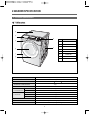
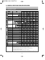
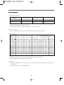
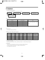
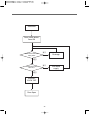
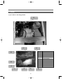
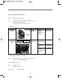
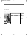
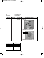
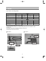
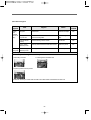
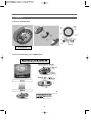
Service Manual Auto Washer / Dry Model : KUD-UD121DCR KUD-UD121WCW DRUM WASHING MACHINE SERVICE MANUAL 1. WHAT IS DRUM?..........................................................................1 2. WASHER SPECIFICATION ..........................................................4 3. OPERATING MECHANISM DIAGRAM.........................................6 4. EACH PART OF DRUM WASHING MACHINE ............................8 5. PARTS LIST BY ASS'Y ...............................................................10 6. CONTROL PART FUNCTION SPECIFICATION ........................25 7. ELECTRONIC FIELD PARTS LIST AND SPECIFICATION .......48 8. WIRING DIAGRAM .....................................................................75 9. TROUBLE SHOOTING REGARDING DRAIN ............................76 10. INSTALLATION .........................................................................77 11. ATTENTION POINT WITH SERVICING ...................................79 1. WHAT IS DRUM WASHING MACHINE? 1. Drum Washing Machine Water consumption is reduced by using the power of the laundry falling (free-fall) created when rotating the drum. With temperature control system, this drum washing machine saves energy and improves washing performance at the same time. 2. Key Features ᶈ Waist Care Designed by the waist, and the most comfortable angle eject into the laundry is convenient and easy to manipulate. ᶈ The World's First Shoes Course Enable to wash shoes. ᶈ DD inverter motor The direct-drive type of which motor is directly connected to drum without an interim chuth, significantly reduces noise and vibration. ᶈ The World's First Steam White Course The Steam White Course save more 50 percent of Electricity, Water, Time than previous White Course. ᶈ Self-Cleaning Course of Drum. Enable to Self-Cleaning of Drum. ᶈ Star Drum Using Star Drum is able to higher Washing Performance and Minimal damage of laundry, water consumption. ᶈ Digital Condensing Dry System. Condensing Dry System with saveing energy. ᶈ The biggest capacity with compact size 12 Kg Capacity enable to wash bigger laundry. ᶈ For pump drainage, the powerful pump speeds up drainage process. ᶈ Sumultaneous supply of cold and hot water As cold and hot water is supplied at the same time heating time and energy is saved. ᶈ Luxury Audio Dial Using the advanced Audio Dial is luxury design of exterior. 1 3. Power System laundry laundry lifter p@d bldc n@d ⍥DD Control: Direct drive type of direct connection between drum and motor ⍥Rotation by powerful high-performance BLDC motor ⍥Pump drainage type for built-in installation and Natural drainage 2 4. Major Functions ῡ Washing When rotating drum after putting in the laundry and detergent into the drum, the laundry are rotated by protrusions (lifters) attached inside the drum. Washing is carried out with bending and impact actions generated by falling of the laundry to the bottom part of drum. ῢ Rinsing Rinsing cleanly washes out detergent and dirt removed from the laundry after washing cycle. ΰ Spin-drying Weak, standard and strong spin cycle can be selected according to types of fabrics to be washed. spinwringing is carried out by rotation (the centrifugal force) of drum according to the designated speed. ῤ Drainage Pump Drainage: Powerful pump for built-in installation and application of filter to remove foreign substances Natural Drainage: Applied Natural Drainage as the same pullsator. 3 2.WASHER SPECIFICATION 1. Product Specification ῡ tQRUG@ V T X U W S Q R DIMENSION(WxDxH) WASH 91 WASHING CONSUMPTION CABINET F 2 FRAME DOOR O 3 PROTECT GLASS 4 PANEL F 5 CASE DETERGENT 6 PLATE TOP 7 CABINET 8 BUTTON DIAL / DRY 51 31 POWER SOURCE CAPACITY 1 82 kg WATER CONSUMPTION CONSUMPTION PARTS NAME 630mm(W) x 792mm(D) x 976mm(H) MACHINE WEIGHT POWER NO 230V/50Hz, 110V/60Hz, 127V/60Hz WASHING 200W (Heating ) ~ 2000W DRY 1200W ~ 2100W WASHING 12 kg SPIN 12 kg DRY 7 kg WASHING TYPE DRUM TYPE DRY TYPE OPERATION WATER PRESSURE Digital condensing dry system 29kPa ~ 784kPa(0.3kgf/cm2~8kgf/cm2) 4 ῢ tQRSG@ V T X U W S Q R DIMENSION(WxDxH) WASH 91 WASHING CONSUMPTION CABINET F 2 FRAME DOOR O 3 PROTECT GLASS 4 PANEL F 5 CASE DETERGENT 6 PLATE TOP 7 CABINET 8 BUTTON DIAL / DRY 51 31 POWER SOURCE CAPACITY 1 82 kg WATER CONSUMPTION CONSUMPTION PARTS NAME 630mm(W) x 792mm(D) x 976mm(H) MACHINE WEIGHT POWER NO 230V/50Hz, 110V/60Hz, 127V/60Hz WASHING 200W (Heating ) ~ 2000W DRY 1200W ~ 2100W WASHING 12 kg SPIN 12 kg DRY 7 kg WASHING TYPE DRUM TYPE DRY TYPE OPERATION WATER PRESSURE Digital condensing dry system 29kPa ~ 784kPa(0.3kgf/cm2~8kgf/cm2) 5 3. OPERATING MECHANISM DIAGRAM 4. WATER SUPPLY PART • Cold Water: 3 holes Cold water, pre-washing • Hot Water: 1 hole • Water supply box, hose Water Supply 6. DRY PARTS • HEATER DRY : OPTION • BLOWER FAN • FAN MOTOR : BLDC • THERMISTOR • THERMOSTAT : FUSE, BI-METAL • CONDENSING SYSTEM • DRY FAN DRIVE → GENERATION OF HEATER’S HEAT → TEMP. SENSOR → 110°C Off 100°C On : OPTION Detergent Container Thermister Door Door Switch 5. DOOR • Door lock S/W • Lock hinge • Door AS: Glass • Gasket Drainage Pump 7. DRAINAGE PART • Drainage pump • Valve housing • Hose 6 Washing Heater 1. CONTROL PART • Main PCB • Front PCB • Harness • Noise filter • Power Cord: 15A Electricity Input Noise Filter Program 2. DRIVING PART • BLDC motor • Drum • Bearing • Spider/ shaft • Tub • Weight balancer BLD C Motor Drum 3. HEATING PART • Water Heater: 1000W ~ 2000W • Washing temperature sensor Thermister 8. SUPPORTER • DAMPER AS : Front 2(70) / Rear 2(110N) • Spring : 2 7 4. EACH PART OF DRUM WASHING MACHINE QN@panel@f@assy UN@main@pcb@as VN@duct@b@as SN@door@as TN@cabinet@f@assy XN@tub@assy WN@base@u@as 8 RN@inlet@box@as J@tub@assy@ QI@bldc@rotor RI@bldc@stator SI@shaft TI@bearing@ UI@spider VI@drum WI@tub 7) 6) 4) assy 3) 5) 2) 1) 9 5. PARTS LIST BY ASS’Y 1. PANEL F AS ῡ tQRUG@ No. PARTS NAME A01 PANEL F OUTER 3614287900 ABS CODE SPECIFICATIONS 1 A02 PANEL F INNER 3614288000 ABS 1 A03 DECORATOR START 3611686300 ABS 1 A04 BUTTON POWER 3616637100 ABS 1 A05 DECORATOR COURSE 3611686200 ABS 1 A06 WINDOW COURSE 3615505700 Trans parency ABS 1 A07 BUTTON DIAL IN 3616637300 ABS 1 A08 BUTTON DIAL OUT 3616637500 Trans parency 1 A09 BUTTON START 3616637600 ABS 1 A10 BUTTON RES 3616637200 ABS 1 A11 BUTTON FUNCTION 3616637700 ABS 1 A12 WINDOW DISPLAY 3615505600 Trans parency ABS 1 A13 CASE HANDLE 3611146800 ABS 1 A14 HANDLE CAP 3612611300 ABS 1 A15 SPRING CASE HANDLE 3615116000 SUS 304, D=0.6 1 A16 CASE PCB F 3611146700 HIPS 1 A17 HOLDER LED 3613054000 ABS 1 A18 HOLDER LED COURSE 3613053900 ABS 1 A19 PCB AS DWD-T120R FRONT PCB ASSY 10 Q’TY 1 REMARK 2. INLET BOX AS No. PARTS NAME CODE SPECIFICATIONS Q’TY REMARK B01 NOZZLE TOP 3618105400 PP 1 B02 NOZZLE UNDER 3618105500 PP 1 B03 INLET BOX 3617510900 PP 1 B04 CASE DETERGENT 3611146400 PP 1 B05 CAP SOFTENER 3610918300 PP 1 B06 CASE LIQUID 3611147900 PP 1 B07 CAP LIQUID 3610918000 PP 1 B08 HOSE INLET 3613272000 EPDM, "U" TRAP 1 B09 CLAMP AS 3611203200 ID=60, WIRE+GUIDE+BOLT+NUT 2 B10 HOSE WATER SUPPLY 3613270900 EPDM ID9.5 OD14.5, L=320mm 1 Combo EPDM ID9.5 OD14.5, L=370mm 1 Wash B11 HOSE WATER SUPPLY 3613270900 EPDM ID9.5 OD14.5, L=355mm 1 B12 HOSE WATER SUPPLY 3613270900 EPDM ID9.5 OD14.5, L=170x2 2 B13 HOSE WATER SUPPLY 3613270900 EPDM ID9.5 OD14.5, L=460mm 1 B14 PIPE JOINT(HOSE INLET) 3614413300 PP 1 B15 HOSE WATER SUPPLY 3613270930 EPDM ID8.5 OD12.5, L=530mm 1 B16 CLAMP HOSE 3611205800 100H, ID=13.8 W=10.0 0.9T 8 B17 VALVE INLET 3615415700 100~130V 1-WAY HOT PP-BRACKET B18 VALVE INLET 3615415070 100~130V 12 1 3-WAY 1 3. CABINET F ASSY 13 No. PARTS NAME CODE SPECIFICATIONS C01 CABINET F C02 PLATE HINGE SUPPORT 3614539800 SPG 0.8 t 1 C03 HINGE DOOR 3612903800 AL 1 C04 CAP HINGE DOOR 3610916500 POM 4 C05 FRAME DOOR O 3612209900 ABS, CR 1 C06 HANDLE COVER 3612611500 ABS 1 C07 HOOK DOOR 3613100900 ZNDC 1 C08 SPRING HOOK 3615115400 SUS304 1 C09 HOOK SHAFT 3613101000 SUS, D=3.0 1 C10 SWITCH DOOR LOCK 3619047210 DL-S1 125V 16A 1 C11 FRAME DOOR I 3612209800 PP 1 C12 PROTECTOR GLASS 3618304300 PC 1 C13 STOPPER DOOR 3615202400 ABS 1 C14 DOOR GLASS 361A110600 GLASS 1 3610813000 SECD 0.8 t 14 Q’TY 1 REMARK 4. CABINET ASSY 15 No. PARTS NAME CODE SPECIFICATIONS D01 NOZZLE AIR 3618103110 PP, DWD-100DR 1 D02 PCB MAIN 3610PCB231 GI 1.6 t 1 D03 FRAME TOP L 3612209400 GI 1.6 t 1 D04 CABINET 3610812900 SGCC 0.8 t 1 D05 COVER BACK AS 3611425540 COVER BACK + PAD CABINET 1 D06 STOPPER SPRING 3615202200 POM, DWD-100DR 2 D07 FIXTURE PLATE 3612008000 POM, 130RP 8 D08 FRAME UPPER 3612209500 SBHG, 1.2 t 1 D09 FRAME LOWER 3612204200 SBHG, 1.2 t 1 D10 HANDLE CABINET 3612608100 PP, DWD-100DR 4 D11 FRAME COVER 3612209600 SBHG, 1.2 t 1 16 Q’TY REMARK 5. BASE U AS 17 No. PARTS NAME CODE SPECIFICATIONS Q’TY E01 BASE U 3610393200 PP, DWD-T120R 1 E02 SUPPORTER LEG 3615303600 PO+, 3.0T 4 E03 FIXTURE LEG 3612006400 ABS, DWD-100DR 4 E04 SPECIAL BOLT 3616029000 10 X 1.25, 51MM 4 E05 FOOT 3612100600 BUTYL, DWD-100DR 4 E06 REACTOR 52G043J002 DWD-100DR, 4A 1 E07 DAMPER FRICTION 361A700150 110N AKS ST=170-260 DL=197.5 LOW NOISE 2 E08 DAMPER FRICTION 361A700110 70N AKS ST=170-260 DL=197.5 LOW NOISE 2 E09 DAMPER PIN 361A700200 AKS D=14.5 4 E10 EMI FILTER(K19B) 3611909300 DWLF-K19(B110),X0.47U.Y1000P.VAR471K.NON FUSE 1 18 REMARK 6. TUB ASSY F22 19 No. PARTS NAME CODE SPECIFICATIONS Q’TY F01 BALANCER WEIGHT 3616109000 DWD-T120R 1 F02 GASKET DRY 3612323900 EPDM 1 F03 NOZZLE SHOWER 3618104000 PP, DWD-100DR 1 F04 DAMPER PIN 361A700200 AKS D=14.5 4 F05 DAMPER FRICTION 361A700110 AKS, 70N 2 F06 TUB FRONT 3618829800 FRPP, DWD-T120R 1 F07 DRUM FRONT 3617003101 SUS, 0.5T 1 F08 LIFTER WASH 361A400600 PP NANO-SILVER 3 F09 DRUM CENTER 3617003010 SUS, 0.6T 1 F10 DRUM REAR 3617003210 SUS, 0.6T 1 F11 SPIDER AS 361A300200 SPIDER(ALDC)+SHAFT(S45C) 1 F12 GASKET TUB 3612324300 L=1810 1 F13 AIR TRAP AS 3610AAR120 DWD-T120R F14 SPRING SUSPENSION 3615115800 1 DWD-T120R 2 F15 UNIT BUBBLE PUMP 3612802410 230V 1 36189L4G00 100V~130V 1 F16 HOSE AIR 3613266300 EPDM 1 F17 TUB REAR 3618829700 FRPP, DWD-T120R 1 F18 BEARING HOUSING 3616304600 ALDC 1 F19 BEARING INNER 3616303100 6206Z 1 F20 BEARING OUTER 3616303200 6205Z 1 F21 UNIT STATOR BLDC 36189L4800 36SLOT 1 F22 UNIT ROTOR BLDC 36189L4900 MAGNET24 1 F23 HEATER WASH 3612802410 230V 2000W 1 3612802440 100-130V 1000W 1 3612802430 110V 1000W 1 F24 HOSE DRAIN I 3613266100 EPDM 1 F25 FIXTURE HEATER 3612009300 SUS0.7T 1 F26 DRAIN MOTOR 3619TAK00 110V 1 F27 DAMPER FRICTION 361A700150 AKS 2 F28 UNIT DRAIN PUMP AS 36189L5K30 220-240V / 50Hz 1 36189L5710 110-127V / 60 Hz 1 20 REMARK 7. DUCT B AS + DUCT PIPE AS 21 No. PARTS NAME CODE SPECIFICATIONS Q’TY REMARK G01 UNIT FAN MOTOR 36189L3Z20 ISM-7780 6DWWA 24V. 1 G02 COVER DUCT 3611428700 ALDC 1 G03 DUCT B UPPER 361A202100 ALCOST 0.5T 1 G04 CLAMP CORD 3611203330 DABE-2, A=9, B=5,3, L=105 3 G05 FAN AS 3611885900 DI33 FAN 1 G06 SCREW TAPPING 7122400811 T2S TRS 4x8 1 G07 SPECIAL SCREW AS 3616030100 TAPTITE P, TRS 4*16, WASHER 1 G08 FUSE TEMPERATURE 361A800120 128ᴱ(G4A0115C) 15A 250V 1 G09 FRAME HEATER FRANGE 3612209700 SBHG 1.2t 1 G10 DUCT B LOWER 361A202200 AL, 3t 1 G11 PACKING THERMOSTAT 3614009900 SILICON 1 G12 SWITCH THERMOSTAT 3619046500 ON 120ᴱ OFF 150ᴱ 230V 1 G13 HEATER DRY 3612801400 230V 2100W 1 3612802100 120V 1200W 1 3612801300 110V 1200W 1 G14 THERMISTOR DRY 361AAAAC30 R40=26.065ὶ, R90=4.4278ὶ 1 G15 PACKING RUBBER 3614009800 SILICON 1 G16 CUSHION DRY 3611570500 NBR, 20 x20 x 3T 2 G17 GASKET SEAL A 3612324200 EPDM FOAM, DIA=5, L=1335 1 G18 GASKET SEAL B 3612320810 EPDM FOAM, L=412, 4.9 x 4.4 x 4.8 1 G19 GASKET INLET 3612323800 EVA, 10 x 211 x 1T 1 G20 DUCT GUIDE 361A202300 AL, 3T 1 G21 DUCT AS 361A200850 T120R 1 G22 CLAMP AS(DUCT) 3611203700 DUCT 2 G23 BELLOWS DUCT 3616403000 EPDM 1 G24 H0SE WATER SUPPLY 3613270900 T120R 1 G25 CLAMP SPRING 3611203800 ID=15.5, T=0.6, B=10 2 22 8. PLATE TOP ASSY No. PARTS NAME CODE SPECIFICATIONS H01 PLATE TOP 3614539900 SECC 1.2T 1 H02 LABEL CAUTION 3613553830 PVC, SILK 1 H03 LABEL INSTALL 3613555700 ART+OPP, WATER VALVE STICKER 1 23 Q’TY REMARK 6. CONTROL PART FUNCTION SPECIFICATION 1. SEQUENCE CHART d p r eN w a s h w a s h i n g r i n s e s p i n s w @s p N@w d b@s mN@s s w @s wQ Hh I wR d b@s mN@s w @s r @Q d b@s mN@s w @s r @R d b@s mN@s w @s r @S d b@s m@s n h @@s s m m t RP R QP X Q R S RP R YP XP SU SP RU TP RU RP QU Q R S R S Q R S R S Q R S R S Q R W U S VP QP ■ ■ ■ ■ ■ ■ ■ ■ ■ ■ ■ ■ ■ XU WU SR RW ■ ■ ■ ■ ■ ■ ■ ■ ■ ■ ■ ■ ■ ■ ■ ■ ■ ■ ■ ■ ■ ■ ■ ■ ■ ■ ■ ■ ■ ■ ■ ■ ■ ■ ■ ■ ■ ■ ■ ■ ■ c @ ■ ■ ■ e ■ ■ ■ r @t @d QZTR QZTW QZUY note QN@i@ @h @s@c L@p @@ @@d N end w s m ■ ■ ■ ■ ■ ■ ■ ■ ■ ■ ■ ■ ■ ■ ■ ■ ■ ■ ■ ■ ■ ■ ■ ■ ■ ■ ■ ■ ■ ■ ■ ■ ■ ■ ■ ■ RZRV ■ ■ RZSV RN@d @s @t @@r @@ @n@c @ @@ N SN@i@c @ @n@c @@TPᴱLh @t @i @W@N @ @ @@N TN@a@@w @t L@w@t @@ N UN@i@ @n@c L@ @@@ @@L@@ @@ @Q@ 24 d w a s h i n g r i n s e s p i n d r y s w @s wQ Hh I wR d b@s mN@s w @s r @Q d b@s mN@s w @s r @R d b@s mN@s w @s r @S d b@s m@s c @ d t d q@@SP b s@s t@@c s s m s h SP ■ R ■ ■ ■ ■ ■ VP UP SU SP RP ■ RU RP QU X QP QU ■ ■ ■ Q ■ ■ ■ ■ ■ R ■ ■ ■ ■ S ■ ■ ■ ■ ■ R ■ ■ ■ ■ ■ S ■ ■ ■ ■ ■ Q ■ ■ ■ ■ r @Q w @ Q ■ ■ ■ S ■ ■ ■ ■ R ■ ■ ■ ■ S ■ ■ ■ ■ Q ■ R ■ S ■ R ■ S ■ Q ■ ■ ■ ■ ■ R ■ ■ ■ ■ W U S VP ■ ■ QPP SP ■ ■ U ■ ■ QP ■ ■ SP ■ VP ■ ■ QP ■ ■ ■ ■ TY SR QZQQ QZTW QZUQ c e c @ c @ end e r @t @d note QN@i@ @d@d@c L@d@@ @@d N RN@c @ @c @@@@@ @N SN@i@ @s @c @c @ @G@ @@d TN@s@@s @ @G@ @ @s@s 25 a w ■ ■ ■ SU eMs n@s s@s b@@c s @w m s s m m s m s RP ■ ■ ■ ■ ■ ■ ■ s @w @s Q ■ ■ ■ ■ ■ ■ ■ s @h RP s QU ■ ■ ■ t RU e s @w QU a QP m W ■ ■ f@w @s Q ■ ■ ■ ■ ■ ■ ■ f@w RU ■ ■ ■ ■ ■ ■ ■ s SP w @s R w VP a wQ UP s Hh I SU h SP i QU n RU g wR RP QU d Q b@s R mN@s S w @s R r @Q S d Q b@s R mN@s S r w @s R i r @R S n K@a d Q s b@s R @ e mN@s S w @s R r @S S d Q R b@s mN@s S w @s R r @T S d Q ■ ■ ■ ■ ■ ■ ■ s b@s R ■ ■ ■ ■ ■ ■ ■ p W i m@s U n S c @c VP ■ ■ ■ ■ ■ ■ ■ end e QP ■ ■ ■ ■ ■ ■ ■ r @t @d QZTW QZUP RZPP RZSR RZQP RZQP QZTW note QN@m @ @@@ @@@ @ @@ M @ N RN@b@ @@s @w @ @@ @@RU@ SN@T@ @ @@ @b@c d t 26 2. Skill of each Sequence RMQN@w@s QI@w@s @ @ c m p s load@sensing w @l o o o d @l d @l h t heating d @l x x w d @l X@@QP@ SP ῡ p @@s@@ @@N ῢ d @l G@ @w @l @@t @@l@s @@nLw LeMw @c N ΰ s@@@ @@@L@ @L@@@N ῤh @ @@@@ @@@ N RI@@w@t w @l c SPᴱ n TPᴱ VPᴱ w SPLTPᴱ s @w VPᴱ YPᴱ s heating@t w@t t@w@t RP RU TU m RU RU UP s RP@HKWI TP VW m RU@HKWI TP WR s SP RU UU m TU RU WP s WU RU QPP m XU RU QQP s RU RU UP m RU RU UP s SP RU UU m SP RU UU s UP RU WU m UP RU WU SPLTPᴱ m SP RU UU VPᴱ m UP RU WU s x QU QU q@SP s x X X b m x RU RU s RP RP TP m RU RU UP h @sB d s@ SPLTPᴱ b@c VPᴱ m SP RU UU YPᴱ m UP RU WU a@w x x x x t@c h x QP QP 27 ῡ ῢ ΰ ῤ w@h @G@ @ @ @ @ N n@c @K@TPᴱ @W@@@ @ @@N i@s @@n@K@TPᴱ @@@ @@TP@N i@ls@ @@ @@SVPL@Q@@@@w@t N SI@e @c @t @@w@m c n w s @w h @s d q@SP b s@ b@c t@c w t PTPᴱ VPᴱ YUᴱ SPTPᴱ VPᴱ YUᴱ PTPᴱ VPᴱ c c c PTPᴱ SPTPᴱ VPᴱ YUᴱ c motor@time@oOoff@H I w s UOQP UOQP UOQP UOQP UOQP UOQP UOQP UOQP x UOQP UOQP UOQP UOQP UOQP UOQP UOQP w h m@w QPOQP QXOV QPOQP QPOQP QPOQU WOQU QPOQP QPOQP QPOQP QPOQP QPOQU WOQU QXOW QPOU QXOW QPOW x ROQU x QXOV QPOQP QPOW QPOQP QPOW QPOQP QPOQP QPOQP QPOQP QPOQU WOQU x QPOSP s QUOQXP QUOQXP QUOQXP QUOQXP QUOQXP QUOQXP QUOQXP QUOQXP x x x QUOQXP QUOQXP QUOQXP QUOQXP x c c QPOU QPOU QPOU QPOU QPOU QPOU QPOU QPOU x QPOU QPOU QPOU QPOU QPOU QPOU QPOU s TU@NN TU@NN TU@NN TU@NN TU@NN TU@NN TU@NN TU@NN TU@NN TU@NN TU@NN TU@NN TU@NN TU@NN TU@NN TU@NN ῡ i@@ @ ῢ i@m@r @@@ L@m@@@ @ @ N ΰ w @w @sL@m@s@ @on@N ῤ c @c @@ @@ @@@@@N@i@@ @s@s N ῥ e @c @t @@w@m@onOoff@t @@@@@s @w @ b@c N ῦ e@t @@e @c @t @@w@m@@s @w @@b@c @@QPOUL QXOVN TI@r Mw @s ῡ i@@@ @ @@ @@ @ ῢ m@ @ @r Mw @s ΰ w @w@s @r Mw @s@@QU@ N ῤ i@w @l @@ @@reset@l L@d@ie@@h @N 28 RMRN@r @s QI@w @s@s w @l @ HI kh RTP RRU RRNYV RSNQX a@r @ @ r @ @ h m ῡ o@@ @@@r @s ῢ i@@r @s L@ @@ @@ @ @ N RI@r Mw @s ῡ a @Q@@@r @s L@ @ @ @@@r Mw @sN SI@r @s w l n w s @w h @s b@c s@ d q@SP b t@c motor@oOoff@H I w t r t mN@s c c c c c c c c c c S S S S S S S S S S S S S S S S S S S S mN@s NN @ TU@NN TU@NN TU@NN TU@NN TU@NN TU@NN TU@NN TU@NN TU@NN TU@NN UOQP UOQP UOQP UOQP UOQP x x UOQP UOQP UOQP QPOU QPOU QPOU QPOU QPOU QPOU RORP QPOU QPOU QPOU TI@d ῡ b @d @s L@w @t N@@ @@@ @N ῢ a @d @s L@d@m@@@on UI@mN@s ῡ m@s@@ @@ @NN@@i@@G@rMs@ @ @RP@ L@@ @ N ῢ i@s @c L@ @@@bMsN 29 RMSN@s@s QI@d ῡ i@@d @s N RI@b @s ῡ i@u @c @L@s@rMsN ῢ bMs@@u@u @ @ L@SUP@NN SI@rHr I@s ῡ f@ @@bMs@@ @@s@s @@r@sN ῢ NN@@ @@ TI@s @s ῡ b @s@ @@N RMTN@e QI@c @c ῡ c @c @@ @@ @@@@@N@i@@SP @L @s@s N ῢ w@@s @ @G@@ @ RI@e ῡ a @QP@ @ @@L @endN ῢ i@@ @ L@@@ N ΰ a @end@L@@N 30 RMUN@d@s QI@@@@ N I@ @@@Ht@ @ @RZSPI dHQI ➞ ➞ dHQTTI ➞ coolingHUI ➞ eHQP I c @c HSPI M^@n@d RI@d@s c n w s @w h @s q@SP d@s max max max max max e a@ @ @m N ῡ a@ @ @m@N SI@c @c ῡ c @c @ @VP@ N TI@e @c @t @@d@s N c @c d cooling w @f t h @oOo@t HᴱI l QPOU QUOU QPOQP QPOUP QQP WPOVP lHs I@ QPOU ROSP ROSP x SV WPOVP i QPOU QUOU QPOQP QPOUP VP QPUOYU n QPOU QUOU QPOQP QPOUP QUP QPUOYU s QPOU QUOU QPOQP QPOUP RPP QPUOYU UI@d@vOv@ ῡ i@@@ @ @RP L@i@d@s @@e@@d@s N VI@cooling ῡ f@@@m@@@@ @@c@s N ῢ t N@@d@@ @@UPᴱ @c@s N ΰ c@ @@@U@N 31 WI@d@h @ ῡ d@h @@@e@@d@s N ῢ s @c @Z@WPᴱ off@O@VPᴱ on ΰ a@c @Z@XPᴱ off@O@WPᴱ on XI@c @c ῡ c @c @ @ @d@s @@SP@N ῢ o@m@@@w @f RMVN@s @s QI@s @ @ ῡ w @s@ @@Q@NL@R@ L@@s @s N RI@s @h ῡ i@ @@ @ @ N@L@ @N ῢ s @h @t N c e n s t WPᴱ WUᴱ YPᴱ t QU QU RP SI@s @w ῡ t@ @@ @@@ @@ @@@ @ N ῢ s @w@t c e n s s t W QP QU RU TI@f@s @w @s ῡ s @ @@ @N ῢ w @s@ @Q@N UI@f@s @w ῡ i@@@G@ @ @ N@@m@w ῢ @RU@ N VI@m@w ῡ s @ @@ 32 h @oOo@ WPᴱOWUᴱ WUᴱOXPᴱ YPᴱOYUᴱ YPᴱOYUᴱ 3. Main Function of PCB Program 3-1. LOAD SENSING 1) Deciding the water level ῡ Normal, White, Eco-White Course will be followed by this process. ῢ Check the water level with dry laundry at the starting wash. ΰ Check the water level by using motor output data during 20 sec, 65rpm. 2) Deciding Spin Starting Step. ῡ Check after finishing washing step with wet laundry. ῢ Checking by using motor output data during 20 sec, 65 rpm. ΰ The Decided data is different depending on loading condition. 3-2. Balance Spin 1) Motor running during balance spin ῡ Spreading the laundry : Rotating the same 45 rpm with left and right direction alternatively. ῢ Unbalance checking point : first step, sheck the U.B at 95 rpm, 160 rpm second step, check the U.B at 95 rpm 350 rpm. Third step at 300 rpm. If the unbalance data is over the criterion This process will be repeated. ΰ After drain, check the unbalance data again. This is so-called balance spin step. 3) Property of balance spin ῡ Conducting 20 times maximum. ῢ If the washer can not pass balance spin step during 20 times, then water will be supplied. ΰ If the washer can not pass 20 times of balance spin, UE error mode will be displayed on '18:88' 33 3-3. DOOR S/W 1) The working principle of Door S/W ῡ Door Locking Bimetal on (3 sec) --> solenoid (supply 20msec pulse 2 times) ῢ Door Unlocking Bimetal off --> solenoid(supply 20msec pulse, until lock) ΰ After door locking all parts can work nomally. ῤ After pressing power button, if the temperature of wash thermistor is over 55ᴱ or the water level is over the safety level, the door will be locked. ῥ The door will be unlocked immediately after all processes are finished. ῦ The door can be opened during processing if there is no problem to unlock. 2) DOOR OPEN SYSTEM ῡ If add the laundry during washing, press the door unlock button. ῢ Door open sequence at abnormal condition. 3-4. Child Lock ῡ Press the "Spin" and "Condensing Dry" button simultaneously during processing. ῢ Under the Child Lock function, only power button is working. ΰ During Child Lock function, CHL will be displayed on '18:88' ῤ In order to unlock Child Lock mode, press "Spin" and "Condensing Dry" simultaneously. 3-5. The sequence of drain ῡ If the checking time to reset point is below 1 min, the remaining drain time is 30 sec. ῢ If the checking time to reset point is over 1 min, the remaining drain time is 2 min. ΰ If the checking time to reset point is over 10 min, OE signal will be appeared on PCB. ῤ If the temperature is over 50ᴱ , the water will be supplied to high water level, then the drain will start. 34 Start/Hold Door unlock button, 2sec ON Water level is less than safety level? no Drainage yes Temperature is less than 50ᴱ? no yes DISPLAY ‘LOCK’ OFF Door Open 35 Cold water supply 5. TEST MODE 5-1. Testing Mode PCB and other electronic parts will be tested without water supply whether they are normal or not. 1) Process press power button --> press "SPIN" button 3 times with pressing "WASH" button --> 'L d' will be shown on LED --> Whenever pressing "TEMP" button 1 time, below process will be occurred. MICOM Ver. --> L C (Lock Closed) --> run (count) ---> b1, b2, b3, b4, b5, b6, b7 -> F (Fan Motor) -> H (Hot V/V) -> C (Cold V/V) -> P (prewashing V/V) -> d ( dry V/V) -> bb (bubble) -> dr (drain motor) -> L O(Lock S/W Open) 2) More details 1 When turn on 'LOCK' signal, all process is conducting normaly. 2 When working starts, the PCB displays all the sensor conditions. 3 In this case, BLDC Motor is not tested. In order to test it, select spin or rinse. 5-2. Continous testing mode 1) Process after pressing "WASH", "RINSE", "SPIN" button simultaniously, press "POWER" button. ALL LED On --> SPIN button ---> ALL LED off --> L C (Lock Close) ---> r (Motor right) --> L (Motor Left) --> F ( Fan Motor) ---> H (Hot V/V) --> C (Cold V/V) --> b (Pre whsh V/V) --> d ( dry V/V) --> bb (bubble) --> h1 (Wash heater)--> h2(Dry heater) --> dr (Drain motor On) -->L O(Lock S/W Open) 2) More tails 1 LED test can be done with all LED On. 2 All sensor conditions will be shown on PCB during processing. 36 6-1. Error Display 6-1. IE (Input Error) - Error in water supply 1) Conditions of Occurrence ῡ In case the designated water level is not reached in 5 minutes during water supply or re-supply 2) All LEDs are turned off and 'IE' blinks in18:88 display. 3) Error buzzer alarm is sounded for 10 seconds per every 10 minutes. 4) Error display is cleared when turning off/ on power. 6-2. OE (Output Error) - Error in drainage 1) Conditions of Occurrence ῡ In case water level does not reach reset point in 10 minutes after drainage starts 2) All LEDs are turned off and 'OE' blinks in 18:88 display. 3) Error buzzer alarm is sounded for 10 seconds per every 10 minutes. 4) Error display is cleared when turning off/ on power. 6-3. UE (Unbalance Error) 1) Conditions of Occurrence ῡ In case main spin-drying is not reached within 20 cycles of balance spin-drying ῢ In case balance spin-drying fails during interim spin-drying, UE occurs as the cycle moves to the next process. 2) All LEDs are turned off and 'UE' blinks in 18:88 display. 3) Error buzzer alarm is sounded for 10 seconds per every 10 minutes. 4) Error mode is cleared by opening door and organizing the laundry in spin-dry chamber, closing door and pressing start/ temporary stop button. Then, spin-drying begins again. 37 6-4. LE (Lock Error) - Door opening error 1) Conditions of Occurrence ῡ When intending to begin cycle by pressing start/ temporary stop button while door is opened 2) All LEDs are turned off and 'LE' blinks in 18:88 display. 3) Error buzzer alarm is sounded for 10 seconds per every 10 minutes. 4) Error display is cleared when turning off/ on power. 6-5. E1 - Water level detection error 1) Conditions of Occurrence ῡ In case water level is below reset or overflow is detected in line test mode 2) Water supply motor is kept on until water level falls below reset. 3) All LEDs are turned off and 'E1' blinks in 18:88 display. 4) Error buzzer alarm is sounded for 10 seconds per every 10 minutes. 5) Error display is cleared when turning off/ on power. 6-6. E2 - Overflow error 1) Conditions of Occurrence ῡ In case water level in water tank is above overflow level due to continuous operation of water supply valve 2) Water supply motor is kept on until water level falls below reset. 3) All LEDs are turned off and 'E2' blinks in 18:88 display. 4) Error buzzer alarm is sounded for 10 seconds per every 10 minutes. 5) Error display is cleared when turning off/ on power. 38 6-7. E4 - Water leakage during washing 1) Conditions of Occurrence ῡ In case water level falls below re-supply even after 15 times of re-supply prior to finishing of water heating 2) All LEDs are turned off and 'E4' blinks in 18:88 display. 3) Error buzzer alarm is sounded for 10 seconds per every 10 minutes. 4) Error display is cleared when turning off/ on power. 6-8. E9 - Abnormalities in water level sensor 1) Conditions of Occurrence ῡ In case water level frequency is of 15KHz or lower and 30KHz or higher during cycle due to abnormalities in water level sensor, etc. 2) All LEDs are turned off and 'E9' blinks in 18:88 display. 3) Error buzzer alarm is sounded for 10 seconds per every 10 minutes. 4) Error display is cleared when turning off/ on power. 39 6-9. Motor-related Error 1) E5 (DC-Link High Voltage) Error ῡ In case DC-link voltage to IPM increases to 450V or higher ῢ Motor operation is stopped and 'E5' is shown in display window. ΰ Error buzzer alarm is sounded for 10 seconds per every 10 minutes. ῤ Error display is cleared when turning off/ on power. 2) E6 (EMG) Error ῡ In case current detected with EMG port is of 20A or higher ῢ Motor operation is stopped and 'E6' is shown in display window. ΰ Error buzzer alarm is sounded for 10 seconds per every 10 minutes. ῤ Error display is cleared when turning off/ on power. 3) E7 (Direction) Error ῡ In case signal of Hall IC is different from the predicted signal according to direction of rotation ῢ Motor operation is stopped and 'E7' is shown in display window. ΰ Error buzzer alarm is sounded for 10 seconds per every 10 minutes. ῤ Error display is cleared when turning off/ on power. 4) E8 (Initial Operation Fail) Error ῡ In case input signal of Hall IC is abnormal due to problems in motor connection, etc. ῢ Motor operation is stopped and 'E8' is shown in display window. ΰ Error buzzer alarm is sounded for 10 seconds per every 10 minutes. ῤ Error display is cleared when turning off/ on power. 6-10. Error in Temperature Sensor 1) H2 Error - Washing temperature sensor open/ short ῡ In case washing temperature sensor is defective or not connected ῢ Error buzzer alarm is sounded for 10 seconds per every 10 minutes. ΰ Error display is cleared when turning off/ on power. 2) H4 Error - Washing temperature sensor overheating ῡ In case temperature detected by washing temperature sensor is 95ᴱ or higher ῢ Error buzzer alarm is sounded for 10 seconds per every 10 minutes. ΰ Error display is cleared when turning off/ on power. 40 3) H5 Error - Water temperature error in wool/ delicate course ῡ In case water temperature in wool/ delicate course is 45ᴱ or higher ῢ Error buzzer alarm is sounded for 10 seconds per every 10 minutes. ΰ Error display is cleared when turning off/ on power. 4) H6 Error - Abnormality in washing heater ῡ Within 15 minutes after heater operation begins; In case standard temperature is of 42ᴱ or lower: If temperature does not increase by 2ᴱ or more In case standard temperature is higher than 42ᴱ: If temperature does not increase by1ᴱ or more ῢ If temperature falls below standard temperature by 2ᴱ or more due to re-supply of water, etc., standard temperature is reset as the current temperature and error check time of15 minutes is reset. ΰ Error buzzer alarm is sounded for 10 seconds per every 10 minutes. ῤ Error display is cleared when turning off/ on power. 5) H8 Error - Washing heater overheating ῡ In case washing heater temperature increases by 5ᴱ or more within 30 seconds when there is no water in tank, etc. ῢ Error buzzer alarm is sounded for 10 seconds per every 10 minutes. ΰ Error display is cleared when turning off/ on power. 41 7. ELECTRONIC FIELD PARTS LIST AND SPECIFICATION no part@@name rHvOhI part@@code bom@@description valve@inlet RRPv SVQUTQUPUP RRPv@ppObracket valve@inlet QPPMQSPv SVQUTQUWPP QPPMQSPv@hot@ppObracket valve@inlet QPPMQSPv SVQUTQUPWP QPPMQSPv@S@way@ppObracket R sensor@@pressure Uv SVQTXRURPP Uv@drumLdnMddPQLdlMdwPQLinlet@@@YP S cord@power@@as k SVQQSSYSTP hPUvvMf@QNUsq@RUPvQVa@ferrite T unit@bubble@pump RRPMRTPv SVQRXPRTQP RRPMRTPv unit@bubble@pump QPPMQSPv SVQXYlTgPP U harness@as k SVQRWYWXPP drumMQQkgNkoreaNdryMfull V harness@earth a SVQRWYSTQP gnOyw@awgQX@ferrite@ᾤRY W fuse@temperature QUa@RUPv SVQaXPPQRP QRXᴱ dfMQRXs@QUa@RUPv@vde X switch@door@lock QPPMQSPv SVQYPTWRQP dlMsQ@QRUv@QVa RSPv SVQRXPRTQP RPPPw QPPMQSPv SVQRXPRTTP QPPPw QQPv SVQRXPRTSP QPPPw RSPv SVQRXPQTPP RQPPw QRPv SVQRXPRQPP QRPPw QQPv SVQRXPQSPP QRPPw switch@thermostat QPPMRUPv SVQYPTVUPP onQRPᴱ offQUPᴱ RSPv@QUa@vde SVQXYlTXPP ẵRVUxRXhLSVslotLRsnesorLSRUTdPRPPP unit@stator@bldc RXt SVQXYlTXSP ẵRVUxRXhLSVslotLRsnesorLSRUTdPRPPPL@RXt@al@coil unit@rotor@bldc RXt SVQXYlTYPP magnetRTLserrationLwrQRSXfPPQ QS thermistor@wash a SVQaaaabQP rRU]QNWPTὶ rXP]QQNYXQὶ QT thermistor@dry d SVQaaaacSP rTP]RVNPVUὶLrYP]TNTRWXὶ QU unit@fan@motor d SVQXYlSzPP ismMWWXPVdwwa@RTvLcwLXpLQTw QV fan@as d SVQQXXVQPP dQSSJTVlLppgfSPELhanyu QW drain@motor QQPv SVQYVtakPP damper@friction QR@a damper@pin emi@filterHkQYbI Q Y QP QQ QR QX QY heater@wash heater@dry SVQaWPPQQP WPn@aks@st]QWPMRVP@dl]QYWNU@low@noise SVQaWPPQUP QQPn@aks@st]QWPMRVP@dl]QYWNU@low@noise QR@a SVQaWPPRPP aks@d]QTNU QR@a SVQQYPYSPP dwlfMkQYLxPNTWuNyQPPPpNvarTWQkNnonMfuse 42 c c spec w ᵅ ᵅ ᵅ ᵅ ᵅ ᵅ ᵅ lpMTYVlLktl@suQPPQMTPPQ@RRW@iec@US ᵅ ᵅ ᵅ ᵅ ᵅ fuse@QRXᴱ dfMQRXs@QUaORUPvL@tube@srgtHidMℨUIwhL@lOw@ulQPQU@awgQX@QPUᴱVPPv ᵅ paVV@RUE@gf@vPL@micow@sOwHbiMmI@QVa@RUPvL@solenoid@RSPv@QSPήL@ptc@heater ᵅ ᵅ ᵅ ᵅ ᵅ ᵅ ᵅ ᵅ ntMQPSnaHUxvIfQUPMQRPL@ᴦUᴱ ᵅ RXt@al@coil v@SQPvdcLvUvLRsensor statorZclass@bLSVslot@tRXL@air@gap@QL@rotor@Zổ RVURXhL@m RT output@wash@QTUwL@torque@SPPkNHTUrpmIL@@ ᵅ ᵅ ᵅ chip@kcdRVShSYYfL@bRUOXU]SYYRkᴦREL@lOw@ulQPPW@awgRT@l]TUPL@mgVRQQVTHketI ᵅ S bldcLmagnetXLvRTvHWRXvI@vUvL ᵅ ᵅ e ᵅ ᵅ damperHWPnI se ᵅ ᵅ damperHQQPnI ᵅ ᵅ M ᵅ ᵅ M fuse 42 W (blue) V (purple) U (pink) T2 (orange) T1 (brown) Ha (yellow) gbt c 43 red red RELAY 4:W/HEATER(blue) 3:P/CORD(blue) L/F (white) GND2 (gray) Vdd2 (pink) GND1 (black) Vdd1 (purple) GNC (black) W (white) V (blue) U (yellow) 5V (red) Hc (gray) Hb (purple) Ha (brown) B/B (white) PRE (orange) D/M (black) L/CHCK (blue) DRY (yellow) COLD (green) r @HsOwI HOT (brown) LOCK 2 (purple) LOCK 1 (gray) 1. PCB PIN r Hh @sOwI red brown wfPUZ@reactor 2. VALVE INLET Classification 3-hole Valve and Hot Water Valve Code 3-hole: 3615416940, Hot Water: 3615416700 Color Gray Coil Resistance 4320 ~ 5280 ή Use Supplying water for washing/ pre-washing and bleach Appearance Washing Water Input Valve Structure Rre-washing Water Input Valve Hot Water Input Valve M4ᴧ4 : CABINET 4 Bleach Input Valve Symptoms of Breakdown Water not supplied Detailed Symptoms Cause Diagnosis of Defect Water supply not Water tap not opened carried, only noise Coil short is heard Water supply not carried out without noise Check for tap opening. Check if resistance between water supply valve terminals is within 4320~5280ή. Excessive foreign Remove water supply hose and check for foreign substances in substances in SUS filter filter. Foreign substances in valve Connector loosened Visually check connector connection status. Coil short Check if resistance between water supply valve terminals is within 4320~5280ή. Wiring short Wiring short -> Conduction test Defect in water level Refer to water level sensor defect check method. sensor Defect in pressure hose Check for blocking of holes in pressure hose. Defect in water supply valve Water is Continuous water continuously supply in power supplied 'on' state (inside tub) Continuous water supply in power 'off' state Defect in water supply Others Water leakage through sides valve assembly, etc. Floater restraint, loosening -> S/W not working Check for leakage through the sides of water supply valve. 44 Solution PCB Error Mode Open water tap. "IE" "IE" Clean out foreign substances from inside the filter. Replace water supply valve. Administer re-insertion. Replace water supply valve. "IE" Replace water level sensor. Replace defect parts. Replace water supply valve. Replace water supply valve. "IE" "IE" "IE" "IE" "E2" "E2" - Water supply not carried out (IE) Defect in Water Supply Continuous water supply (IE) • Suspension of water supply • Tap frozen • Tap closed • Hot & cold water hose switched for connection • Low water pressure (0.2kgf/cm or less) • Blocking of water supply valve filter by foreign substances • Defect in cold & hot water valve • Defect in connection of water supply terminal (not connected) • Defect in pressure switch • Defect in water supply relay drive circuit • Defect in PCB • Water supply relay open • Defect in water supply valve • Leakage in air hose (air leakage from pressure switch hose) • Air trip blocked, damaged • Defect in pressure switch • Defect in drainage valve: Continuous water supply • Blocking by foreign substances in drainage bellows • Defect in PCB • Water supply relay short Immediate water supply when power is turned on • Defect in PCB Water supply continued when power is turned off • Defect in water supply valve 45 • Water supply relay short Symptoms of Inspection Spot Breakdown Inspection Method Inspection Result Problem Identified 1) Suspension of water supply 2) Water tap locked 3) Cold-hot water hose incorrectly - Cold/ hot water hose switched -Defect in cold/ hot water connected -Large amount of rust, sand and hose assembly 4) If no defect is found, dismantle water dust, etc. -Defect in cleaning of water supply hose and check water supply supply filter (blocked) valve filter. Water supply not carried out Water 1) Measure coil resistance in water supply valve supply valve. 2) Remove top cover and visually check for separation of water supply valve terminal connector and wiring short/ connection status. 3) In case water valve operation sound is heard, but water supply is not carried out, check for blocking of water supply valve or restraint on plunger. Pressure 1) Check for ‘E9’ in display window. Switch Repair Method -Assemble cold/ hot water hose correctly. -Clean water supply filter. -Replace water supply valve. -Try reconnection or remove elements of connection defect. -5.3kW or higher -Coil short -Connector loosened/ not inserted -Connection defect -Electric wire short -Sound and defect in water supply due to foreign substances in bellows -Electric wire short -Structural defect in water supply valve -Try reconnection or remove elements of connection defect. -Replace water supply valve. -E9 -Loosening of pressure S/W terminal or electric wire short -Defect in pressure S/W -Connect terminal of pressure S/W. -Connect terminal of PCB. -Replace pressure S/W. Water supply not carried out PCB 1. Check PCB pin connector insertion status. 2. Power is supplied to water supply valve terminal, but water supply is not administered. Electric wire easily loosened when tugged PCB water supply circuit open, damaged (water supply relay operation not carried out) Pin connector housing not inserted Defect in water supply circuit Completely insert connector housing. Replace PCB. Continuous water supply PCB 1. Immediate supply when power is turned on PCB water supply circuit or relay short (continuous conduction to valve) Water supply relay short Replace PCB. Defect in water supply valve Replace water supply valve. Water 1. Check if water supply is continuously Water supply bellows supply valve carried out even if power is not on. blocked/ deformed Drainage 1. Check for normal operation of water -Not closed due to foreign -Foreign substances in valve -Remove foreign supply valve/ water supply status. drive motor substances. housing substances inside drainage (valve 2. Check if water is drained through -Remove foreign -Foreign substances housing drainage hose. housing) substance. -Defect in drive motor -Wire caught by foreign 3. Check for foreign substances inside -Replace drive motor. restoration substances outside drive valve housing. motor 4. Check for foreign substances in drive -Forced restoration not possible motor wire. 5. Forcefully restore SUS wire. 46 3. Water Level Sensor 1) Spec. of Water Level Sensor (kHz) HEATER SAFETY 24.55 STEAM 24.736 O/F: Forced drainage is necessary as water level is high. When this level is reached, water supply must be stopped and drainage must be forcefully administered. RESET 25.2 LOW 23.2 RESET : MID 23.75 RINSE 23.18 ADD WATER OVERFLOW 22.96 22.6 Low: Small load of laundry, therefore considered to be water level of 'low' 1. Spin-drying begins 30sec after drainage level reset is reached. Medium: Large load of laundry Medium High: Water level for rinsing 2. Heater operation level Safety: Door open possible Door opened only when water level is below safety level 2) Breakdown Analysis Symptoms Detailed Symptoms Cause Diagnosis Solution PCB Error Mode Continuous Water valve normal water supply "E9" Occurrence in water level sensor 30kHz or higher Defect in pressure sensor hose Check for holes. Replace hose. "E2" Blocking of pressure sensor hose Visual checking Remove foreign substances. "E2" Connector loosened Visually check connector connection status. Administer re-insertion. "E9" Wiring short Wiring short -> conduction test 47 "E9" 4. POWER CORD 1) Specificafion Classification Rated Cord Thickness Color DEC 250V/15A 1.5sq Gray Code Type 3611340430 LP-31 SJT Length Remarks 2.3m - 2) Assembly 4 embossed parts in cabinet -> To prevent loosening after assembly -> SS: 2 special screws -> LG: Forced indentation [Before] [After] . CONNECTOR -> #1806 Housing 3P Used: Using both ends only and not the hole in the middle (materials highly resistant to flame) -> To prevent fire caused by high current 48 5. DOOR LOCK SWITCH part@code description SVQYPTWRPP door@lock@@dlMsQ@RUPv@ptcMsolenoid@type 1) DOOR LOCK S/W 49 4) Diagnosis of Defect Symptoms Detailed Symptoms Cause Diagnosis of Defect Solution Ticking noise Tick' during initial operation and 'tick-tick' during temoprary suspension: 'DF' type only Normal noise Normal sound generated during solenoid operation when 'sliding CAM' is locked/ unlocked to close or open door. LE' Continuous occurrence of 'tick' noise and 'LE': 'DF' type only Connector loosened Visually checking connector connection status 1. 'LE' occurrence without 'tick' noise in 'DF' type Door does not open. Error Mode – Insert connector. "LE" Terminal loosened from Referring to door lock S/W dismantling connector and checking methods below Insert connector. S/W 4 or 5 terminal "LE" Door not completed closed - Completely close door. "LE" Abnormality in hook of door - Replace door AS. "LE" Defect in catch CAM operation Occurrence of continuous 'tick' noise unlike normal sound Replace door S/W. "LE" Connector loosened Visually checking connector connection status Insert connector. "LE" Terminal loosened from Referring to door lock S/W dismantling connector and checking methods below Insert terminal. S/W 2 or 3 terminal "LE" Breaking of solenoid coil Replace door S/W. "LE" Referring to picture below Power failure, forced power off during operation PCB MICOM' cannot open door in case of power failure or forced power S/W off during operation. Door can be opened in the max. of 5min. No power failure and power on Water in drum Checking if water level is higher than safety level Inside the drum hot Prevention of door opening to prevent burn caused by hot laundry after drying Others Door opens after drainage. – Door does not open normally in case of loosening of connector/ terminal and breaking of solenoid coil during operation. Administer measures after test according to the following method. 50 1. Heater 1) Spec of Heater of Washing Machine E C G Classification D B A I J F 51 H Parts name A DUCT COVER B FAN MOTOR C HEATER DRY D DUCT B LOWER E VALVE INLET(DRY) F THERMOSTAT G THERMISTOR H DUCT B UPPER I FAN AS J FUSE TEMPERATURE 2) Dry Function Diagram T : Thermistor (CONTROL HEATER’S TEMPERATURE ) DRY DUCT HEATER T FAN MOTOR WATER SUPPLY CONDENSING DUCT DRUM DRAIN HOUSING While rotating DRUM, DRY HEATER applice heat to air and FAN blows it into DRUM evaporating water in the laundry. • Evaporated water is sucked into CONDENSING DUCT, and condensed in DUCT contacting WATER SUPPLY (condensed water is extracted through DRAIN HOUSING). • Dry function is performed by continuous repetition of evaporating and condensing circulation as above. 3) Temp- Time Graph During Dry Cycle DRYING PROCESS éॴݘܖĸÅ ZONE TEMP. ٦ʭ PREّٝ HEATING ZONE INSIDE TEMPERATURE drum@ OF DRUM ǷҜ٦ʭ ĸÅ TIME ֫Å 52 4) Dry Course COURSE LOW TEMP. IRON DRY COURSE Heater control temperature is 60°C On/70°C Off Drying Time is 110min according to Load Sensing Data Heater control temperature is 95°C On/105°C Off, with good condition for ironing Drying Time is 60min according to Load Sensing Data Cupboard Heater control temperature is 95°C On/105°C Off, drying time is 150 min STRONG Heater control temperature is 95°C On/105°C Off, drying time is 200 min SELECTING TIME Heater control temperature is 95°C On/105°C Off, customer can select the drying time out of 1:00, 1:30, 2:00 In order to check the drying temperature during process going on : --> press the "DRY" button, the display shows as below. UPPER LED: Temperature for DRY REMAIN TIME Ǯ֫ڼÅ The current temperature is 98ᴱ Ҟ LOWER LED: Temperature for WASH 53 5) TROUBLE SHOOTING OF DRY SYSTEM ✦ HEATER DRY Function : heating the air during dry • FAILURE MODE : * "H7" - The air cannot be heated to 10°C during 2 min. • CHECKING METHOD : * Check the resistance of heater coil and replace with new one. ✦ Thermistor Function : sensing the air temperature. • FAILURE MODE : * The air cannot be heated even though water is supplied. * "H1" - shot or cut-off * "H3" - air temp. is reached over 150°C • CHECKING METHOD : * Check the resistance of thermistor, replace with new one. ✦ FUSE TEMPERATURE function : protecting from the fire hazard or overheating, if the temp., rises over 128°C, power supply will be cut-off. • Pictures FIXED BY WASHER +SCREW • FAILURE MODE : Dry is not performed. • CHECKING METHOD : Check if fuse is short, and replace with new one. 54 ✦ SWITCH THERMOSTAT(BIMETAL) function : control the duct temperature, if the temp reached over 150°C, all power supply will be cut. and if the temp go down 120°C the power will be ON. protecting overheating by cutting off heater power supply if the temperature rises over 150°C, and reoperating heater by connecting heater power supply if the temperature falls under 120°C. • OPERATING TEMPERATURE • PICTURE OPEN TEMPERATURE(OFF) 150°C ± 5°C CLOSE TEMPERATURE(ON) 120°C ± 5°C ✦ UNIT FAN MOTOR function : circulating the inside air during dry process. • SPEC • PICTURE ITEMS SPEC RATING VOLTAGE 24V RPM MOTOR 3700 ± 10% DUCT FAN AS 1900 ± 10% ROTAING DIRECTION CW • FAILURE MODE : * E3 shown : FAN MOTOR cannot work. • CHECKING METHOD : Check the FAN MOTOR is short, and replace with new one. 55 6) LACK OF DRY PERFORMANCE • Situation : after drying, the clothes still get wet. cause) ☞The laurdry amount is more than the recommendation capacity 7.0kg. ☞Condensing cold water is not supplied. ☞Clogging Bellows Duct results in poor air circulation. checking method) part name checking point checking results BELLOWS DUCT VALVE INLET CONDENSING HOSE repair method clogging bellows duct heater was overheated owing to poor air circulation clean the bellow duct no water supply from inlet valve VALVE INLET connector slipped out connect normally VALVE INLET broken replace valve inlet BELLOW DUCT VALVE INLET +Condensing HOSE jurge ill-connection of connect normally condensing hose to duct pipe • Situation after drying, the clothes was soaked and hot. cause) ☞ The dry is done from bad spin performance because of unbalance. ☞no spin was done before the dry had started. • Situation : PCB shows "H1" or "H3". cause) ☞Thermistor is broken. ☞Thermistor is short or cut-off. countermeasures) ☞replace the Thermistor. 56 • Situation : PCB shows "H7". cause) ☛ Dry heater is cut-off. ☛ Fuse temp. is cut-off. repaire method) ☛ replace the Dry heater. ☛ replace the Fuse temp. checking point part name HEATER FUSE TEMPERATURE checking results repaire method dry Heater is short or cut-off. replace the dry Heater. SENSOR TEMP. Thermistor is short or cut-off. replace the Thermistor. FUSE TEMP. FUSE TEMPERATURE is cut-off. HEATER DRY THERMISTOR 57 replace the FUSE TEMPERATURE. • situation : PCB shows "E3". ☞FAN MOTOR can not work. ☞Replace the Fan Motor. cause) countermeasures) part name checking results repair method FAN MOTOR fan motor failure replace fan motor disassemble process of Fan Motor 1Disassemble Duct Cover As from Duct B As (Screw 4EA) DUCT COVER AS 2Disassemble FAN AS From Duct Cover As (Fixed by 8mm NUT) Fixed By 8mm NUT 3Disassemble the FAN MOTOR(SCREW 3EA) Remarks) control times of each parts during dry process parts Control time MOTOR 15 sec On, 5sec Off DRAIN MOTOR Continous working FAN MOTOR Continous working DRY HEATER 95°C On, 105°C Off INLET VALVE 30sec On, 5sec Off 58 Washing Heater Temp. Sensor Table temp ᴱ MTP MSY MSX MSW MSV MSU MST MSS MSR MSQ MSP MRY MRX MRW MRV MRU MRT MRS MRR MRQ MRP MQY MQX MQW MQV MQU MQT MQS MQR MQQ MQP MY MX MW MV MU MT MS MR MQ min kή RXRNYQT RVVNVTR RUQNTSR RSWNRPX RRSNYPP RQQNTTP QYYNVXS QXXNVVY QWXNSTW QVXNVVX QUYNUXX QUPNYYY QTRNYSW QSUNSVV QRXNRUS QRQNUVV QQUNRSP QPYNRWQ QPSNVVU YXNSXW YSNTQV XXNVPS XTNPWR WYNXPV WUNWXX WRNPPP VXNTPX VUNPRQ VQNXRU UXNXQP UUNYVS USNRQT UPNVRP TXNQWQ TUNXUW TSNVWP TQNUYT SYNVSP SWNWWS SVNPQV rRU@Z@QQNYXQkή ᴦ TNPTE rXP@Z@QNWPTkή ᴦ SE bRUOQPP@Z@SWVPk@ᴦ QE normal max temp min normal max temp kή kή ᴱ kή kή kή ᴱ RYXNVUP SQTNSXW P STNSUR SUNYWU SWNUYY TP RXQNTQV RYVNQYQ Q SRNWWV STNSQX SUNXVQ TQ RVUNSQQ RWYNQYP R SQNRXT SRNWTY STNRQT TR RUPNRUR RVSNRYV S RYNXVY SQNRVR SRNVUU TS RSVNQVU RTXNTSP T RXNURX RYNXUR SQNQWW TT RRRNYWX RSTNUQV U RWNRUV RXNUQV RYNWWV TU RQPNUSW RRQNSYR V RVNPTT RWNRTR RXNTTP TV QYXNXXU RPYNQPQ W RTNXYS RVNPSS RWNQWT TW QXWNYVW QYWNUXW X RSNXPQ RTNXXW RUNYWR TX QWWNWSQ QXVNWYS Y RRNWVT RSNWYX RTNXSQ TY QVXNQRY QWVNVWP QP RQNWXP RRNWVT RSNWTX UP QUYNPTY QVWNPYY QQ RPNXSV RQNWWS RRNWQP UQ QUPNURW QUXNQQW QR QYNYSY RPNXSR RQNWRU UR QTRNURV QTYNVXU QS QYNPXW QYNYSX RPNWXX US QSUNPPY QTQNWVV QT QXNRWW QYNPXX QYNXYY UT QRWNYTU QSTNSRT QU QWNUPV QXNRWY QYNPUR UU QRQNRUR QRWNRWT QV QVNWWP QWNUPW QXNRTT UV QQTNYUY QRPNVTW QW QVNPVY QVNWWR QWNTWU UW QPYNPSY QQTNTQS QX QUNTPR QVNPWR QVNWTS UX QPSNTVW QPXNUTW QY QTNWVW QUNTPW QVNPTV UY YXNRRP QPSNPRT RP QTNQVR QTNWWS QUNSXS VP YSNQTQ YWNVWY RQ QSNUWV QTNQUX QTNWTQ VQ XXNSVQ YRNVTY RR QSNPQX QSNUWT QTNQSP VR XSNXVP XWNYQT RS QRNTXV QSNPQW QSNUTX VS WYNVRR XSNTUV RT QQNYXP QRNTXW QRNYYS VT WUNVRX WYNRUU RU QQNTYW QQNYXQ QRNTVU VU WQNXTP WUNRWR RV QQNPSW QQNTYY QQNYVR VV VXNRWP WQNUQX RW QPNUYX QQNPTP QQNTXR VW VTNYPR VWNYWX RX QPNQWY QPNVPQ QQNPRT VX VQNWRT VTNVSW RY YNWXP QPNQXS QPNUXW VY UXNWRT VQNTXU SP YNTPP YNWXV QPNQWR WP UUNXRY UXNTTS SQ YNPSV YNTPU YNWWU WQ USNPYW UUNUWS SR XNVXX YNPTR YNSYU WR UPNUQW URNXVT SS XNSUV XNVYU YNPSS WS TXNPXQ UPNSPU ST XNPSY XNSVS XNVXV WT TUNWWY TWNXXY SU WNWSW XNPTW XNSUW WU TSNUYT TUNUYT SV WNTTX WNWTT XNPTQ WV TQNURX TSNTRU SW WNQWP WNTUU WNWSY WW SYNUWT TQNSWU SX VNYPU WNQWX WNTUP WX SWNWRU SYNTSU SY VNVUR VNYQR WNQWS WY 59 min normal max temp kή kή kή ᴱ VNTPS VNVUS VNYPS XQ VNQVY VNTPY VNVTX XR UNYTV VNQWV VNTPU XS UNWSR UNYUR VNQWR XT UNURW UNWSX UNYTY XU UNSRP UNURS UNWRU XV UNQSQ UNSRU UNUQX XW TNYTY UNQSU UNSRQ XX TNWWT TNYUS UNQSQ XY TNVPW TNWWX TNYUP YP TNTTS TNVPX TNWWR YQ TNRXY TNTTW TNVPU YR TNQTQ TNRYR TNTTT YS SNYYY TNQTT TNRYP YT SNXVR TNPPR TNQTR YU SNWRR SNXUV SNYYP YV SNUYU SNWRS SNXUR YW SNTWS SNUYV SNWRP YX SNSUU SNTWT SNUYS YY SNRTS SNSUW SNTWQ QPP SNQSS SNRTS SNSUS QPQ SNPRY SNQSU SNRTP QPR RNYRY SNPSP SNQSR QPS RNXSS RNYSP SNPRX QPT RNWTP RNXST RNYRX QPU RNVUT RNWTT RNXSU QPV RNUVY RNVUV RNWTS QPW RNTXW RNUWQ RNVUT QPX RNTPX RNTXY RNUVY QPY RNSSS RNTQP RNTXW QQP RNRUX RNSSR RNTPW QQQ RNQXW RNRUY RNSSQ QQR RNQQY RNQXX RNRUW QQS RNPUT RNQRP RNQXW QQT QNYYQ RNPUU RNQQY QQU QNYRX QNYYP RNPUQ QQV QNXVY QNYRX QNYXX QQW QNXQR QNXVY QNYRW QQX QNWUX QNXQS QNXVX QQY QNWPU QNWUX QNXQQ QRP min normal max kή kή kή QNVPS QNVUS QNWPS QNUUU QNVPS QNVUR QNUPX QNUUV QNVPS QNTVS QNUQP QNUUV QNTQY QNTVT QNUPY QNSWW QNTRQ QNTVU QNSSV QNSWY QNTRR QNRYW QNSSY QNSXQ QNRUY QNSPP QNSTR QNRRR QNRVR QNSPR QNQXV QNRRV QNRVU QNQUR QNQYQ QNRRY QNQQY QNQUW QNQYT QNPXW QNQRT QNQVQ QNPUW QNPYS QNQRY QNPRW QNPVS QNPYX PNYYY QNPSS QNPVW PNYWQ QNPPU QNPSX PNYTT PNYWW QNPQP PNYQX PNYUP PNYXR PNXYS PNYRT PNYUU PNXVX PNXYY PNYSP PNXTU PNXWU PNYPU PNXRR PNXUQ PNXXQ PNWYY PNXRW PNXUV PNWWW PNXPU PNXSS PNWUV PNWXT PNXQQ PNWSV PNWVS PNWYP PNWQV PNWTS PNWVY PNVYW PNWRS PNWTY PNVWY PNWPT PNWRY PNVVQ PNVXV PNWQP PNVTT PNVVX PNVYR PNVRW PNVUQ PNVWT PNVQP PNVST PNVUW PNUYU PNVQW PNVTP PNUWY PNVPR PNVRT PNUVU PNUXV PNVPX PNUUP PNUWR PNUYS PNUSV PNUUW PNUWX rTP@Z@RVNPVUkή ᴦ SE rQPP@Z@SNSkή ᴦ QQNQE bTPOQPP@Z@TPRUk@ᴦ RE Day Heater Temp. Sensor Table tHᴱI P Q R S T U V W X Y QP QQ QR QS QT QU QV QW QX QY RP RQ RR RS RT RU RV RW RX RY SP SQ SR SS ST SU SV SW SX SY TP TQ TR TS TT TU TV TW TX TY UP UQ UR US UT UU r QTRNUU QSUNUU QRXNYS QRRNVX QQVNWV QQQNQW QPUNXW QPPNXV YVNQR YQNVR XWNSW XSNSS WYNUQ WUNXX WRNTT VYNQW VVNPW VSNQS VPNST UWNVX UUNQV URNWV UPNTX TXNSQ TVNRU TTNRX TRNTQ TPNVS SXNYT SWNSR SUNWX STNSQ SRNYQ SQNUX SPNSQ RYNPY RWNYS RVNXS RUNWW RTNWV RSNXP RRNXW RQNYY RQNQU RPNST QYNUW QXNXT QXNQS QWNTV QVNXQ QVNQY QUNVP QUNPS QTNTX QSNYV QSNTV r QVRNRQ QUTNPY QTVNTQ QSYNQW QSRNSR QRUNXV QQYNWT QQSNYV QPXNUP QPSNSR YXNTS YSNWY XYNTP XUNRT XQNSP WWNUV WTNPQ WPNVU VWNTV VTNTS VQNUV UXNXS UVNRT USNWW UQNTS TYNRP TWNPX TUNPW TSNQU TQNSR SYNUX SWNYS SVNSU STNXU SSNTQ SRNPU SPNWU RYNUP RXNSR RWNQY RVNQQ RUNPW RTNPY RSNQU RRNRU RQNSY RPNUW QYNWX QYNPS QXNSQ QWNVR QVNYV QVNSS QUNWS QUNQU QTNVP r QXTNQR QWTNWR QVUNXU QUWNTX QTYNUY QTRNQS QSUNPY QRXNTU QRRNQV QQVNRR QQPNVQ QPUNSP QPPNRW YUNUQ YQNPQ XVNWT XRNWP WXNXW WUNRT WQNXP VXNUS VUNTS VRNTY UYNWP UWNPU UTNUS URNQS TYNXV TWNVY TUNVT TSNVX TQNXR TPNPT SXNSV SVNWU SUNRR SSNWV SRNSW SQNPT RYNWW RXNUW RWNTR RVNSR RUNRW RTNRW RSNSQ RRNTP RQNUS RPNVY QYNYP QYNQS QXNTP QWNWQ QWNPT QVNTP QUNWY tHᴱI UV UW UX UY VP VQ VR VS VT VU VV VW VX VY WP WQ WR WS WT WU WV WW WX WY XP XQ XR XS XT XU XV XW XX XY YP YQ YR YS YT YU YV YW YX YY QPP QPQ QPR QPS QPT QPU QPV QPW QPX QPY QQP QQQ r QRNYXP QRNURP QRNPWX QQNVUU QQNRTX QPNXUW QPNTXS QPNQRS YNWWW YNTTU YNQRU XNXQX XNURT XNRTP WNYVW WNWPU WNTUR WNRQP VNYWV VNWUQ VNUST VNSRV VNQRU UNYSQ UNWTU UNUVU UNSYR UNRRU UNPVT TNYPY TNWUY TNVQU TNTWV TNSTQ TNRQR TNPXV SNYVU SNXTY SNWSV SNVRW SNURR SNTRP SNSRR SNRRW SNQSU SNPTS RNYUT RNXVW RNWXT RNWPT RNVRV RNUUQ RNTWX RNTPX RNSTP RNRWT r QTNPVV QSNUUW QSNPVY QRNVPQ QRNQUS QQNWRR QQNSPY QPNYQS QPNUSS QPNQVX YNXQW YNTXQ YNQUW XNXTV XNUTX XNRVQ WNYXU WNWQY WNTVT WNRQX VNYXR VNWUU VNUSV VNSRU VNQRS UNYRW UNWSY UNUUX UNSXS UNRQU UNPUS TNXYV TNWTV TNVPP TNTVP TNSRU TNQYT TNPVX SNYTW SNXRY SNWQV SNVPV SNUPQ SNSYY SNSPP SNRPU SNQQS SNPRT RNYSW RNXUT RNWWT RNVYV RNVRQ RNUTX RNTWW RNTPY 60 r QUNRPS QTNVTS QTNQPU QSNUYQ QSNPYW QRNVRT QRNQWQ QQNWSV QQNSQY QPNYQY QPNUSU QPNQVW YNXQS YNTWT YNQTX XNXST XNUSS XNRTT WNYVV WNVYY WNTTR WNQYU VNYUW VNWRY VNUPY VNRYW VNPYS UNXYW UNWPX UNURV UNSUQ UNQXR UNPQY TNXVR TNWQQ TNUVV TNTRU TNRXY TNQUY TNPSS SNYQQ SNWYS SNVXP SNUWQ SNTVU SNSVW SNRWR SNQXP SNPYR SNPPV RNYRS RNXTR RNWVT RNVXY RNVQV RNUTV tHᴱI QQR QQS QQT QQU QQV QQW QQX QQY QRP QRQ QRR QRS QRT QRU QRV QRW QRX QRY QSP QSQ QSR QSS QST QSU QSV QSW QSX QSY QTP QTQ QTR QTS QTT QTU QTV QTW QTX QTY QUP r RNRQQ RNQTY RNPYP RNPSR QNYWW QNYRS QNXWP QNXRP QNWWQ QNWRS QNVWX QNVSS QNUYP QNUTX QNUPX QNTVX QNTSP QNSYS QNSUW QNSRS QNRXY QNRUV QNRRU QNQYT QNQVT QNQSU QNQPW QNPXP QNPUS QNPRW QNPPR PNYWX PNYUT PNYSQ PNYPY PNXXW PNXVV PNXTV PNXRV r RNSTS RNRWY RNRQW RNQUX RNQPP RNPTS QNYXY QNYSV QNXXU QNXSV QNWXX QNWTQ QNVYV QNVUR QNVQP QNUVY QNURY QNTYP QNTUS QNTQV QNSXQ QNSTV QNSQS QNRXQ QNRTY QNRQY QNQXY QNQVP QNQSR QNQPU QNPWY QNPUS QNPRX QNPPT PNYXP PNYUX PNYSU PNYQT PNXYS r RNTWW RNTQQ RNSTW RNRXU RNRRU RNQVV RNQQP RNPUU RNPPR QNYUP QNYPP QNXUR QNXPU QNWUY QNWQU QNVWR QNVSP QNUYP QNUUP QNUQR QNTWU QNTSY QNTPT QNSWP QNSSW QNSPU QNRWT QNRTT QNRQU QNQXV QNQUX QNQSQ QNQPU QNPXP QNPUU QNPSQ QNPPW PNYXT PNYVR 7. HEATER 1) Spec of Heater of Washing Machine wash maker irca irca irca irca rated RRPv RSPv QSPv QQPv RPPPw RPPPw QPPPw QPPPw SVQRXPPXPP SVQRXPRTQP SVQRXPRTTP SVQRXPRTSP consumption@power part@code dryer maker irca irca irca irca rated RRPv RSPv QRPv QQPv RQPPw RQPPw QRPPw QRPPw SVQRXPPYPP SVQRXPQTPP SVQRXPRQPP SVQRXPQSPP consumption@power part@code Temp. Fuse of Washing Heater (184°C CUT OFF TYPE) : Located inside heater to prevent fire, etc. caused by heating without water due to breakdown of water level sensor, etc. : Cut-off in app. 1min in case of overheating, heater temp. of app. 270°C : Washing heater must be used under water. ᵀWash Heater ᵀDay Heater Drying Temp. Sensor Washing Temp. Sensor Dry Heater Wash Heater 61 2) Breakdown Diagnosis Breakdown Symptoms Solution PCB Error Mode Check for short Connect the cut-off part. "H6" Check for short: Normal if 23.3~25.7ohm between both terminals of washing heater Replace washing heater. "H6" Connector/ terminal loosening Check for loosening: Common for drum Insert terminal. "H6" Defect in washing heater temp. sensor Measuring resistance between both terminals of sensor: Replace temp. sensor. "H2" Overheating of Defect in washing washing water heater temp. sensor Measuring resistance between both terminals of sensor: Replace temp. sensor. "H2" or "H4" Cause Washing Wiring short water not heated (common for Washing heater or drum) temp. fuse short Diagnosis Heater Replacement * How to Replace Washing Heater and Temp. Sensor 1. Dismantling Connector 2. Loosening Earth and Heater Nuts 3. Replacing Heater and Temp. Sensor 4. Administer assembly in reverse order and make sure to fasten heater nuts first before the earth nuts. 62 7. HEATER 1) Structure of BLDC Motor bldc@motor 2) Power Transmission System of BLDC Motor 63 3) Specification Classification 1. General 2. Performance 3. Structure Item BLDC : DD Motor Rated Voltage Vm = 310 [Vdc], Hall IC Voltage 5 [Vdc] Insulating Structure Type B, insulator method External Appearance Shaft connection and stator connection structure, Air-gap : 1mm No. of Poles 24 poles, Core: 36 slots, Layer: [30mm] Consumption Power 390[W]±10[%], during washing (picked value) RPM During Washing: 45RPM, During Spin-drying:1300RPM Output Characteristics Torque: 300Kgf.cm (washing: 45rpm) Current: 1.5A (washing: 45rpm), 2.5A (spin-drying: 800rpm) AC Input Terminal - Washing: 250Wo, Spin-drying: 380Wo Stator Resistance ø265x30H U(blue) - V(purple) : 13.8Ω[at 75°C] V(purple) - W(pink) : 13.8Ω[at 75°C] W(pink) - U(blue) : 13.8Ω[at 75°C] cf) Motor resistance at ambient temp. of 0 ~ 35°C 7.04 ~ 8.1Ω Rotor Magnet : 24 segments, bracket, serration Hall IC 2-sensor Control Type, Top Central Angle: 7.5 degrees Signal Error Angle (phase difference): 90±5 degrees (based on electric angle) 64 8. WIRING DIAGRAM 65 9. TROUBLE SHOOTING REGARDING DRAIN 1) Structure of Dran Parts by TUB hose@drain@i housing@valve drain@motor valve@air@as 2) Checking Methods • Situation : * "OE" is shown on PCB. * Not finishing drain during 10 min. * The water level can not reach to RESET POINT during 10 min of drain. Checking Methods Replacing methods * Check the hose drain O condition; twisted or frozen. * replace HOSE DRAIN O * Check the hose drain O condition, blocked. * clean the inside of Filter. * DRAIN MOTOR is broken. * replace DRAIN MOTOR 66 10. INSTALLATION GUIDE 1) Related Parts and Configuration FIGURES PARTS NAME REMARKS FIXTURE UP/DOWN AS special fixture@up screw@up fixture down special screw down FIXTURE UP AS (3612008200) : L= 109mm FIXTURE DOWN AS (3612008300) : L=143mm ῡ Remove Fixture UP/DOWN AS ῢ Adjust Leg UNIT SERVICE WRENCH LEG ADJUST AS fixture leg foot 2) INSTALLATION PROCESS 1Remove the FIXTURE UP/DOWN AS Removal Method Remarks ☞ Disassemble the FIXTURE UP/DOWN AS by turning CCW direction. ☞ Please keep FIXTURE UP/DOWN AS for later use. ☞ When fixing FIXTURE UP/DOWN AS, turn it CW direction. 2Insert CAP HOLDER(4EA) after removing FIXTURE UP/DOWN AS. CAP HOLDER 67 3Please install the DRUM WASHING MACHINE properly on even and hard floor as below. 4Adjust the level of washer using LEG ADJUST AS. Adjusting Method Remarks ☞ If turned CW, the LEG ADJUST AS moves the washer upward. ☞ If turned CCW, the LEG ADJUST AS moves the washer downward. 5After adjusting level, fix SPECIAL BOLT. Adjusting Method Remarks ✰ Please fix the SPECIAL BOLT by rotating it CCW in order to prevent washer vibration. 68 11. ATTENTION POINT WITH SERVICING No Item 1 Replacing Thermistor Dry 2 Replacing Duct B As & Duct Pipe 3 Replacing & Repairing Inlet Valve 4 Replacing Hose Drain 5 Replacing HOSE A,B,C 6 Replacing Heater Wash 7 Replacing “Thermistor Wash” 8 Assembling “Hinge Door” Part Name Thermistor Dry DUCT B AS & DUCT PIPE Inlet Valve Hose Drain HOSE A,B,C Heater Wash Thermistor Wash Hinge Door 9 (Dis)assembling “Door AS” 10 (Dis)assembling “Motor AS” Door As 11 Damper AS Damper AS MOTOR AS Checking Point Keep the Packing from seperating (Hold Packing when replacing) Keep the Packing from folding Check the sealing between Duct Pipe & Duct B AS Use only screw M4*8 for fixing Inlet Valve Keep the sealing condition of Tub O tightly Check the assembling order between INLET BOX & Hose A,C : Pre Wash-Cold Unfastening the nut for fixing earth first then unfasten the nut for fixing heater At assembling the heater dry, check if the assembling condition between fixture heater is tight.(little gap on left & right) At fastening the nut for fixing the heater wash, keep the protrusion length of bolt to 10~12mm. (if under 10mm, water can leak, and if over 12mm, fixture heater can deform) Unfasten the Nut for fixing heater, replace the thermistor, and fasten the nut for fixing heater At fastening screw for fixing Door AS, be careful so that scratching at the related parts does not happen : If the scratching happens, it is possible to be claimed about appearance damage Be careful about the up/down direction of Door Glass : Keep the indication point of the part code downward. To avoid the injury on the hand, grip the rim of the rotor At initiating the assembling operation of the stator, grip the stator and fasten the screw; at unfastening the screw, grip the stator so that it does not fall. Fixed 4 Dampers with spring when assemble. 69 DAEWOO ELECTRONICS CORP. 686, AHYEON-DONG MAPO-GU SEOUL, KOREA C.P.O. BOX 8003 SEOUL, KOREA TELEX: DWELEC K28177-8 CABLE: “DAEWOOELEC” S/M NO. : PRINTED DATE: Apr. 2008