1
Pegaso™
Powered Mobile Dock
Installation Guide
Datalogic Mobile, Inc
1505 Westec Dr.
Eugene, Oregon 97402
Telephone: (541) 743-4800
Fax: (541) 743-4900
An Unpublished Work - All rights reserved. No part of the contents of this documentation or the procedures described therein
may be reproduced or transmitted in any form or by any means without prior written permission of Datalogic Mobile, Inc. or its
affiliates or subsidiaries ("Datalogic" or “Datalogic Mobile”) . Owners of Datalogic products are hereby granted a non-exclusive,
revocable license to reproduce and transmit this documentation for the purchaser's own internal business purposes. Purchaser
shall not remove or alter any proprietary notices, including copyright notices, contained in this documentation and shall ensure
that all notices appear on any reproductions of the documentation.
Should future revisions of this manual be published, you can acquire printed versions by contacting your Datalogic representative. Electronic versions may either be downloadable from the Datalogic Mobile website (www.mobile.datalogic.com) or provided on appropriate media. If you visit our website and would like to make comments or suggestions about this or other
Datalogic publications, please let us know via the “Contact Datalogic” page.
Disclaimer
Datalogic has taken reasonable measures to provide information in this manual that is complete and accurate, however, Datalogic reserves the right to change any specification at any time without prior notice.
Datalogic is a registered trademark of Datalogic S.p.A. and the Datalogic logo is a trademark of Datalogic S.p.A. all licensed to
Datalogic Mobile, Inc. All other trademarks and trade names referred to herein are property of their respective owners.
Patents
This product may be covered by one or more of the following patents:
4,861,972 • 4,866,257 • 4,879,456 • 5,198,649 • 5,208,449 • 5,212,372 • 5,247,161 • 5,311,000 • 5,440,110 • 5,481,098 •
5,493,108 • 5,508,505 • 5,664,231 • 5,671,374 • 5,686,716 • 6,041,374 • 6,412,698 • 6,415,978 • 6,454,168 • 6,478,224 •
6,513,714 • 6,536,670 • 6,561,427 • 6,585,157 • 6,923,377 • 7,108,170 • D377345 • CA2,188,399 • Other U.S. and Foreign Patents Pending.
Table of Contents
Table of Contents.................................................................................................. i
Datalogic Pegaso™ Powered Mobile Dock Warranty ........................................... iii
Electrical Warnings, Safety Precautions & Regulatory Statements ..................... iv
Safety Precautions ........................................................................................................ iv
Introduction ........................................................................................................ 1
Manual Overview ...........................................................................................................1
Document Conventions ..................................................................................................1
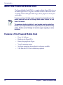
About the Powered Mobile Dock .......................................................................................2
Features of the Powered Mobile Dock ..........................................................................2
Electrical Specifications: ..................................................................................................3
Unpacking ....................................................................................................................3
Electrical Considerations ..................................................................................... 5
Electrostatic Build-up ......................................................................................................5
Ground Contact Anti-Static Straps ..............................................................................6
Electrical Accessories ......................................................................................................7
Electrical Accessory Matrix ..............................................................................................7
Electrical System Connections ..........................................................................................8
Connection to +12V .................................................................................................8
Connection to +24V, +36V and +48V Systems ............................................................9
Mounting Options .............................................................................................. 11
Ram Ball Mounting Assembly ......................................................................................... 11
Components, Materials and Tools ............................................................................. 12
Attaching the Ram Ball to the Mobile Dock ................................................................ 12
Ram Ball Assembly (sold separately) ........................................................................ 12
Final Assembly ...................................................................................................... 13
Inserting/Removing the Pegaso ...................................................................................... 14
Inserting the Pegaso in the Dock .............................................................................. 14
Removing the Pegaso from the Dock ........................................................................ 15
Power and Peripheral Device Connections ......................................................... 17
Connections on the Dock ......................................................................................... 17
Power Connection .................................................................................................. 17
Battery Charging ................................................................................................... 18
COM Port Connection .............................................................................................. 18
USB Connection ..................................................................................................... 19
Appendix. Troubleshooting ................................................................................ 21
Hardware Troubleshooting ............................................................................................. 21
Issues with Power to the Dock ................................................................................. 21
Installation Guide
i
Technical Support ........................................................................................................ 21
Datalogic Mobile Website Support ............................................................................. 21
Reseller Technical Support ...................................................................................... 21
Telephone Technical Support ................................................................................... 21
Appendix. Accessories and Peripherals ............................................................. 23
Overview .................................................................................................................... 23
Index ................................................................................................................ 27
ii
Pegaso™ Powered Mobile Dock
Datalogic Pegaso™
Powered Mobile Dock Warranty
Warranty
Falcon products are guaranteed against defects in materials and workmanship for the period specified at the time of sale. This warranty shall apply to Falcon
Portable Data Terminals (PDT's), Base Stations for the Falcon and Chargers for the Falcon. Cables, mounts and other accessory items are specifically warranted for a period of 90-days from product purchase. Customer must notify Datalogic of the claimed defect before the expiration of the Warranty period and
obtain from Datalogic a return authorization number for return of the product to designated Datalogic service center. If Datalogic determines Customer’s
claim is valid, Datalogic will repair or replace product without additional charge for parts and labor. Customer shall be responsible for packaging and shipping
the product to the designated Datalogic service center, with shipping charges prepaid. Datalogic shall pay for the return of the product to Customer if the
shipment is to a location within the country in which the Datalogic service center is located. Customer shall be responsible for paying all shipping charges,
duties, taxes, and any other charges for products returned to any other locations.
Warranty is subject to the limitations and exclusions set forth in the paragraphs that follow.
WARRANTY SET FORTH ABOVE IS IN LIEU OF ANY OTHER WARRANTIES, EXPRESS OR IMPLIED, INCLUDING MERCHANTABILITY AND FITNESS.
Exclusions
Warranty coverage shall not apply to any claimed defect, failure or damage which Datalogic determines was caused by: abuse, neglect, improper use of
product; failure to provide product maintenance, including but not limited to cleaning of the display in accordance with product reference guide; installation or
service of product by other than Datalogic representatives; use of product with any other instrument, equipment or apparatus; modification or alteration of
product or units with Warranty Void labels that have been tampered with. External cables and replacement of upper window/cartridge due to scratching,
stains or other degradation will not be covered under the Warranty. External power supplies returned for service must be accompanied by the original product
for performance of service.
Returned products that Datalogic Mobile, Inc. has determined are not covered by Warranty, will be charged Datalogic Mobile, Inc. standard repair rates then
in effect for repair of product. Replacement of display due to scratching, stains or other degradation will not be covered under Warranty. If a product is determined to be not repairable customer will be notified and product may be returned to customer at their request. A minimum repair fee may be charged.
Limitation of Liability
DATALOGIC'S REPAIR OR REPLACEMENT OF DEFECTIVE PRODUCT AS SET FORTH ABOVE IS THE CUSTOMER’S SOLE AND EXCLUSIVE REMEDY ON ACCOUNT OF CLAIMS OF BREACH OF WARRANTY OR PRODUCT DEFECT. UNDER NO CIRCUMSTANCES WILL DATALOGIC BE LIABLE
TO CUSTOMER OR ANY THIRD PARTY FOR ANY LOST PROFITS, OR ANY INCIDENTAL, CONSEQUENTIAL IN-DIRECT, SPECIAL OR CONTINGENT
DAMAGES REGARDLESS OF WHETHER DATALOGIC HAD ADVANCE NOTICE OF THE POSSIBILITY OF SUCH DAMAGES.
Assignment
Customer may not assign or otherwise transfer its rights or obligations under Warranty except to a purchaser or transferee of product. No attempted assignment or transfer in violation of this provision shall be valid or binding upon Datalogic.
Risk of Loss
Customer shall bear risk of loss or damage for product in transit to Datalogic. Datalogic shall assume risk of loss or damage for product in Datalogic's possession or product being returned to Customer by Datalogic, except such loss or damage as may be caused by the negligence of Customer, its agents or
employees. In the absence of specific written instructions for the return of product to Customer, Datalogic will select the carrier, but Datalogic shall not
thereby assume any liability in connection with the return shipment.
Installation Guide
iii
Electrical Warnings, Safety Precautions & Regulatory Statements
Electrical Warnings, Safety
Precautions & Regulatory Statements
Safety Precautions
The Datalogic Pegaso is a device suitable for both Commercial and Industrial
applications, ready for installation in mobile environments using the Powered
Mobile Dock. However, there are some safety precautions you should take to
protect the PDA from unnecessary damage.
Do not place the Pegaso near a television or radio receiver.
Keep the PDA away from magnets and from magnetic fields.
CAUTION
iv
Pegaso™ Powered Mobile Dock
Chapter 1
Introduction
Manual Overview
•
Chapter 1 (this chapter) provides an introduction to the features of the
Powered Mobile Dock.
•
Chapter 2 specifies important electrical considerations to observe when
installing the unit.
•
Chapter 3 contains instructions for mounting.
•
Chapter 4 describes the various peripheral connections made to the
Dock, and their functions.
Document Conventions
Formatting conventions are used throughout this guide to provide a consistent
method for representing the user interface and mobile mount dock. This guide
also provides special conventions for information of high interest, in the form
of notes, cautions, and warnings.
Notes contain information that is helpful and recommended. They provide
information that is critical to operations and/or procedures described in this
manual.
Cautions inform you that proper handling (adherence to the procedures
described) is required to avoid damage to equipment and/or property.
CAUTION
Warnings alert you to potential physical harm or injury. These statements do
not include potentially fatal hazards, which would be designated as ‘DANGER’
blocks. Use of this product does not warrant the need for a DANGER block.
WARNING
Installation Guide
1
Introduction
About the Powered Mobile Dock
The Powered Mobile Dock (PMD) is a rugged cradle for Pegaso PDAs, for use
on mobile applications. This guide is intended to address some of the factors
to consider when installing the PMD on gas, diesel, propane or electric powered forklifts.
To ensure you have the latest version of manuals and instructions for this
product, download them from the Datalogic Mobile website listed on the back
cover of this manual.
The procedures describe installation for most standard mounting applications;
however, if your target installation does not generally match any of the mounting
options detailed, contact Datalogic for technical support regarding a custom
installation.
Features of the Powered Mobile Dock
2
•
Power On Indicator
•
Holder for the Pegaso PDA
•
Battery charging for the Pegaso
•
Versatile mounting options
•
Serial port connection for peripherals (with power available)
•
USB Mini AB OTG Port available for peripherals
Pegaso™ Powered Mobile Dock
Electrical Specifications:
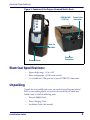
Figure 1. Features of the Pegaso Powered Mobile Dock
USB Mini AB
OTG Port
Power Cable
Connector
Power-On
Indicator
Release Button
Serial Port
Connection
Electrical Specifications:
•
Input voltage range: +12 to +18V
•
Power consumption: <50 MA with no load
•
+5v available on COM port and as part of USB OTG Connection
Unpacking
Unpack the unit carefully and ensure you received everything you ordered.
Refer to your packing slip for an exact list of items delivered, which may
include some or all of the following items:
•
Powered Mobile Dock
•
Power Charging Cable
•
Installation Guide (this manual)
Installation Guide
3
Introduction
•
Ram Ball Mount Kit
• Ram Ball Assembly
• Assorted Screws
• Any additional accessories required for your installation
If any parts are missing, please contact your dealer or refer to “Troubleshooting” on page 21 for Datalogic Mobile Technical Support contact information.
4
Pegaso™ Powered Mobile Dock
Chapter 2
Electrical Considerations
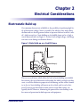
Electrostatic Build-up
One common characteristic of forklifts is the possibility of producing high levels of electrostatic voltage. Static is created by the wheels as they move about
the floor and can also be generated when an operator slides on or off of a vehicle's cloth-covered seat. Static buildup on the forklift frame can be as high as
several thousand volts (see Figure 2). At these levels of high voltage, a discharge
can cause severe damage to electronic devices.
Figure 2. Static Build-up on a Forklift Frame
Positive Charge (+)
Negative Charge (-)
There are several factors which affect the levels of static buildup on a forklift.
For instance, the type of materials used to make the wheels can help to reduce
static, as well the conductive properties of the flooring and the relative humidity in the air. Static buildup will remain on the vehicle until it can be dissipated. Lowering the front forks to make contact to the floor surface can
typically do this. However, eliminating the potential for static buildup is the
best means of protection for both operator and equipment.
Installation Guide
5
Electrical Considerations
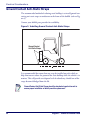
Ground Contact Anti-Static Straps
The recommended method of reducing static buildup is to install ground contacting anti-static straps or conductors to the frame of the forklift (refer to Figure 3).
Contact your forklift parts provider for availability.
Figure 3. Installing Ground Contact Anti-Static Straps
Ground Contact
Anti-Static Straps
It is recommended that more than one strap be installed on each vehicle to
help eliminate or reduce the potential for static buildup while the vehicle is in
motion. This will provide an adequate level of redundancy, should one of the
straps become dislodged from the lift.
Ground Contact Anti-Static Straps should be checked at regular intervals to
ensure proper installation or identify need for replacement.
6
Pegaso™ Powered Mobile Dock
Electrical Accessories
Electrical Accessories
Installation of the PMD may require accessory electronic equipment for
proper and safe operation. Some of this equipment may not be available
through Datalogic, but could be available through your dealer, forklift parts
provider, or other suppliers. See Appendix A, “Accessories and Peripherals” on
page 23.
DC/DC Converter. Voltage step down device used to power the PDA from
+24, +36 and +48 volt battery systems.
DC Conditioner/UPS. Used to provide backup DC power during sags or
interruptions in battery voltage due to peak loads or disconnect.
Delay Timer. Provides automatic shut-off of power to a PDA or other equipment, to reduce battery drain.
Noise Spike/RF Filter. Used to suppress high voltage and RF voltage
spikes on the power system.
Electrical Accessory Matrix
Table 1 summarizes the accessory recommendations and options available
depending on the forklift voltage application. This matrix should be used only
as a reference and may not include accessories for all applications.
Table 1. Electrical Accessories
Forklift System Voltage
Accessory
12 volt
24 volt
36 volt
48 volt
DC/DC Converter
Not Required
Required
Required
Required
DC Conditioner/UPS
Optional*
Not Required
Not Required
Not Required
Delay Timer
Optional*
Optional*
N/A
N/A
Noise Spike/RF Filter
Recommended
Recommended
Recommended
Recommended
5-Amp Dock In-Line Fuse
Required
Required
Required
Required
*Ensure that the device being installed is properly rated for use on your mobile platform.
Installation Guide
7
Electrical Considerations
Electrical System Connections
This section covers electrical connection to +12V, +24V, +36V and +48V systems.
CAUTION
Proper installation requires that source power connections be made directly
to the mobile platform’s positive and negative battery terminals. It is
important to maintain electrical isolation when installing the Powered
Mobile Dock and any accessory equipment, to ensure safe and proper
operation. Do not make any electrical connections directly to the chassis of
the forklift.
Connection to +12V
Figure 4 illustrates a typical wiring connection for a +12 volt system. The
input voltage operating range of the dock will allow direct connection to the
battery terminals. However, the use of a 5-Amp fuse is required, and a Noise
Spike/RF filter is highly recommended.
Accessory equipment may also be required depending on your application,
Refer to Table 1 on page 2-7. Read and follow all manufacturer's installation
instructions carefully.
Figure 4. Wiring Diagram for +12V Systems
Fuse each device according to
manufacturer’s recommendation
Pos
DC Conditioner/UPS
(Optional)
+
5-Amp In-Line Fuse
(Required)
Dock
Power Cord
Red (Pos)
Black (Neg)
Neg
-
Noise/Spike Filter
(Recommended)
Delay Timer
(Optional)*
Use crimp connectors
for all wire connections
* ENSURE that the device being
installed is properly rated for use
on your mobile platform.
8
Pegaso™ Powered Mobile Dock
Electrical System Connections
Connection to +24V, +36V and +48V Systems
Figure 5 illustrates a wiring diagram for +24, +36 and +48 volt systems. The
use of a DC/DC converter is required to step down the battery voltage for use
by the PDA.
Proper installation requires that source power connections be made directly
to the mobile platform’s positive and negative battery terminals. It is
important to maintain electrical isolation when installing the PMD and any
accessory equipment, to ensure safe and proper operation. Do not make
any electrical connections directly to the chassis of the forklift.
CAUTION
When using any optional equipment caution must be taken to ensure that
+24, +36 or +48VDC does not exceed any voltage rating for these devices. Follow all manufacturer's installation instructions carefully.
Some DC/DC converters provide internal Noise Spike/RF filtering. The use
of an additional filter is optional.
Figure 5. Wiring Diagram for +24V, +36V and +48V Systems
In-Line Fuse
(integral to converter)
Pos
+
Neg
-
DC/DC
Converter
(Required)
Pos
IN
Neg
+
OUT
5 Amp In-Line Fuse
(Required)
Red (Pos)
Power Cord
Black (Neg)
-
Use crimp connectors
for all wire connections
Installation Guide
9
Electrical Considerations
NOTES
10
Pegaso™ Powered Mobile Dock
Chapter 3
Mounting Options
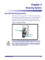
Ram Ball Mounting Assembly
This chapter outlines the steps needed to assemble and mount the Powered
Mobile Dock using the Ram Ball mount accessory. The Ram Ball and mounting assembly, shown in Figure 6, combine to form an extremely flexible
mounting assembly. This assembly allows wide range of rotation for the
Mobile Dock. It can be mounted on any flat horizontal or vertical surface.
Figure 6. The Ram Ball Mount
Ram Ball
Mounting
Assembly
CAUTION
Install only on properly grounded mobile platforms. If this Dock is used on an
electric vehicle, ensure that no part of the PMD and PDA can come into contact
with the vehicle chassis. Electrical discharges can develop on these vehicles,
which can damage the PMD and/or PDA. Refer to “Electrical Considerations”
starting on page 5 for important information.
Installation Guide
11
Mounting Options
Components, Materials and Tools
•
Four M3.5 screws for mounting Ram Ball to PMD (supplied)
•
Phillips head screwdriver
•
Ram Ball Assembly (sold separately)
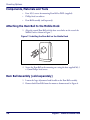
Attaching the Ram Ball to the Mobile Dock
1. Align the second Ram Ball with the four screw holes on the rear of the
Mobile Dock as shown in Figure 7.
Figure 7. Installing the Ram Ball on the Mobile Dock
2. Secure the Ram Ball to the mounting area using the four supplied M3.5
x 15mm Phillips head screws.
Ram Ball Assembly (sold separately)
1. Loosen the large adjustment knob handle on the Ram Ball assembly.
2. Remove both Ram Balls from the mount as demonstrated in Figure 8.
12
Pegaso™ Powered Mobile Dock
Ram Ball Mounting Assembly
Figure 8. Ram Ball Assembly
Ram Balls
Adjustment
Knob
Screws
3. Use four screws (customer supplied) to secure one of the Ram balls to
the desired mounting surface. Set the other Ram ball aside to use later in
the assembly process.
4. Re-attach the Ram Ball Assembly to the Ram Ball you just affixed to the
mounting surface.
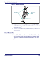
Final Assembly
1. Insert the Ram Ball, mounted to the rear of the Mobile Dock assembly,
into the Ram Ball assembly you earlier affixed to the mounting surface
(see Figure 9). Tighten the adjustment knob to secure the Ram Ball in
place.
Installation Guide
13
Mounting Options
Figure 9. Installing the Mobile Dock Assembly on the Mount
Ram Ball
Ram Ball
Assembly
Adjustment
Knob
2. Loosen the Adjustment Knob slightly to tilt the Mobile Dock to the
desired mounting angle. Re-tighten the Adjustment Knob securely.
3. Route and connect all cables (see “Power and Peripheral Device Connections” starting on page 17 for more on connections). If you haven’t
already prepared the power connection, reference “Electrical Considerations” starting on page 5 for wiring information.
Inserting/Removing the Pegaso
Inserting the Pegaso in the Dock
To insert a Pegaso into the Powered Mobile Dock, perform the following steps:
1. Slide the Pegaso into the Powered Mobile Dock.
2. Push gently downwards to insert the Pegaso until it is firmly seated in
the Dock.
14
Pegaso™ Powered Mobile Dock
Inserting/Removing the Pegaso
Figure 10. Inserting the Pegaso into the Powered Mobile Dock
Insertion of the Pegaso in the Dock is complete.
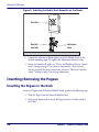
Removing the Pegaso from the Dock
To remove the Pegaso from the Dock:
1. Grasp the Pegaso PDA with one hand, while pushing the Release Button
with the other.
2. Lift the Pegaso straight upward to remove it from the Dock.
Installation Guide
15
Mounting Options
Figure 11. Removing the Pegaso from the Dock
Removal of the Pegaso from the Dock is complete.
16
Pegaso™ Powered Mobile Dock
Chapter 4
Power and Peripheral
Device Connections
This chapter describes connection of peripheral devices that are provided with
or available for the Pegaso PMD system. For more on power connections, see
“Electrical Considerations” starting on page 5.
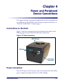
Connections on the Dock
Figure 12 shows the connection located on the bottom of the dock. See the
following pages for more information about these connections.
Figure 12. Cable Connections
USB OTG port
COM port
Input Power
connection
Power Connection
Insert the DC power cord at the power port on the bottom of the dock. When
power is applied to the dock, the Power-On LED will light.
Installation Guide
17
Power and Peripheral Device Connections
Also refer to “Electrical Considerations” starting on page 5 for complete information and wiring diagrams detailing power connection.
For non-mobile applications, an AC power supply adapter is available to power
the PMD. See “Accessories and Peripherals” on page 23. Contact your local
distributor or Datalogic sales for additional information.
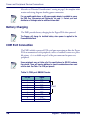
Battery Charging
The PMD provides battery charging for the Pegaso PDA when powered.
The Pegaso will charge its installed battery when power is applied to the
Powered Mobile Dock.
COM Port Connection
The PMD includes a powered DTE serial port connection to allow the Pegaso
PDA to communicate with peripherals, such as a handheld scanner or a portable printer. +5v is available on pin 9 of the port connector for power to a
peripheral.
Some peripherals may not follow all of the specifications for RS-232 hardware
flow control. These will require additional or special considerations when used
with the dock. See Table 2 for COM port pinouts.
Table 2. COM port DB9M Pinouts
18
Pin No.
Signal
1
2
3
4
5
6
7
8
9
DCD
RXD
TXD
DTR
GND
DSR
RTS
CTS
+5 @ 500Ma
Tied
Pegaso™ Powered Mobile Dock
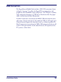
USB Connection
The Pegaso Powered Mobile Dock includes a USB OTG connection (shown
in Figure 12 on page 17) to allow the Pegaso PDA to communicate with
peripherals such as handheld scanners and printers. The USB port is automatically configured to function as a USB host or client device when the proper
cable is inserted into the Mini AB connector.
If a Mini A connector is inserted into the PMDs USB connection the device
will assume a host port function. In this mode the USB port will supply up to
500ma of current to power the client device such as a scanner or printer. If a
Mini B connection is inserted into the PMDs USB connection the device will
assume a client port function. In this mode the device will respond to a host
PC system as a client device.
Installation Guide
19
Power and Peripheral Device Connections
NOTES
20
Pegaso™ Powered Mobile Dock
Appendix A
Troubleshooting
Hardware Troubleshooting
Issues with Power to the Dock
•
Ensure that the power connector is pushed securely into the power plug.
•
When power to the unit is turned on, a light will appear on the Dock.
Refer to the Pegaso Quick Reference Guide (QRG) for information about powering on the Pegaso and a description of its LED functions.
Technical Support
Datalogic Mobile Website Support
The Datalogic Mobile website (www.mobile.datalogic.com) is the complete
source for technical support and information for Datalogic products. The site
offers product support, warranty information, product manuals, product tech
notes, software updates, demos, and instructions for returning products for
repair.
Reseller Technical Support
An excellent source for technical assistance and information is an authorized
Datalogic reseller. A reseller is acquainted with specific types of businesses,
application software, and computer systems and can provide individualized
assistance.
Telephone Technical Support
If you do not have internet or email access, you may contact Datalogic technical support at (541) 743-4802.
Installation Guide
21
Troubleshooting
NOTES
22
Pegaso™ Powered Mobile Dock
Appendix B
Accessories and Peripherals
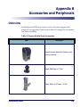
Overview
Installation of the PMD may require accessory electronic equipment for
proper and safe operation. Contact your reseller or Datalogic sales for information about availability.
Table 3. Pegaso Mobile Dock Accessories
Item
Description
Pegaso Powered Mobile Dock (Mounting hardware not included)
Mount, RAM Base w/ 1.5" Ball
Mount, RAM 5.5" 2x Socket, 1.5" Ball
Installation Guide
23
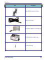
Accessories and Peripherals
Item
Description
Mount, RAM 2.5" Wide Clamp Base w/1.5" Ball
(Accommodates up to 2.5" wide posts)
Mount, RAM 3.5" 2x Socket, 1.5" Ball
Mount, RAM 6" Base Plate
Mount, RAM 7.35" Assy w/ 2x 1.5" BALLs
Kit, RAM Mount, Base w/ 1.5" ball, 5.5" socket,
2.5" wide clamp w/1.5" ball. (Includes one each)
24
Pegaso™ Powered Mobile Dock
Overview
Item
Description
Mount, RAM 5.25" Assy w/ 2x1.5" BALLs
Power Cord, Bare lead, 8'
DC Converter, 18-55VDC IN / 13.8V 10Amp Out
DC Noise Spike Filter, 4-60VDC, 8Amp
Kit, Inline Fuse 5 Amp
Installation Guide
25
Accessories and Peripherals
NOTES
26
Pegaso™ Powered Mobile Dock
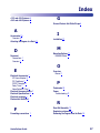
Index
+12V and +24V Systems 8
+36V and +48V Systems 9
G
Ground Contact Anti-Static Straps 6
A
Accessories 23
Overview 23
Attaching the Pegaso to a Dock 14
D
Document
Conventions 1
Overview 1
E
Electrical Accessories 7
AC Power Adapter 8
DC Conditioner 7
DC/DC Converter 7
Delay Timer 7
Noise Spike/RF Filter 7
Electrical Accessory Matrix 7
Electrical Specifications 3
Electrical warnings iv
Electrostatic Build-up 5
I
Installation 17
M
Mounting Options 11
RAM Ball Mount 11
O
Overview
Manual 1
P
Peripherals 23
Power
Troubleshooting 21
R
F
Formatting conventions 1
Installation Guide
Ram Ball Assembly 12
Regulatory statements iv
Removing the Pegaso from the Dock 15
27
Index
S
Safety precautions iv
Static Build-up on a Forklift Frame 5
Style conventions 1
T
The Ram Ball Mount 11
Troubleshooting 21
Power 21
28
U
Unpacking 3
W
Warranty iii
Wiring Diagram for +12V and +24V Systems 8
Wiring Diagram for +36V and +48V Systems 9
Pegaso™ Powered Mobile Dock
Corporate Headquarters
Datalogic S.p.A.
Via Candini, 2
40012 Lippo di Calderara di Reno
Bologna - Italy
Telephone: +39 051 3147011
Fax: +39 051 726562
www.mobile.datalogic.com
Datalogic Mobile, Inc.
1505 Westec Dr.
Eugene, OR 97402
Telephone: (541) 743-4800
Fax: (541) 743-4900
©2008 Datalogic Mobile, Inc.
822501120 (Rev X1)
1/08