1
Direct Vent Gas Fireplace
Installation, Operation and Owner’s Manual
This manual covers the following appliances for use in North America ONLY:
Trisore 95, Trisore 100H, Trisore 140, Bidore 95, Bidore 100H,
Bidore 140, Lucius 140, Lucius 140 T, Lucius 140 C 1/3,
Lucius 140 C 2/3, Modore 95, Modore 100H, Modore 140,
Optica, Bioptica
Element4 Gas Fireplaces
June 20141
EuropeanHome.com
TABLE OF CONTENTS
Important Safety Information
3
User Information
7
Specifications and Dimensions
8
Clearances
27
Gas and Electric
33
Venting
34
Enclosing the Fireplace46
Fire Media
53
Operating the Fireplace58
Maintenance
61
Warranty65
Venting System Installation Instructions
Appendix One
Massachusetts Certification
Appendix Two
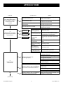
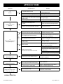
Troubleshooting Flowchart Appendix Three
IMPORTANT SAFETY INFORMATION
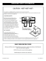
CAUTION - HOT! HOT! HOT!
This appliance is a HEATING appliance and it does become very hot in operation.
UNDER ANY CIRCUMSTANCES, DO NOT PLACE any object, furniture, draperies or other item LESS THAN 36”/90 cm) IN
FRONT OF THE GLASS OF THE FIREPLACE.
HOT SURFACES
36"
36"
90cm 90cm
Radiant heat can heat surfaces such as
the surround and trims of the fireplace to
temperatures that, although approved
safe, can be quite uncomfortable to touch particularly for children and pets. Children
and pets should always be supervised when
in the room where the appliance is located.
Remote control handset should be kept out of
reach of children. In the presence of children,
we STRONGLY RECOMMEND that you install in
front of the fireplace:
a fire screen or, to protect
A
A
young toddlers, a “hearth gate”.
36"
36"
90cm 90cm
CHILDREN AND PETS
36"
90cm
36"
90cm
Do not put furniture or
other objects in this space
in front of the fireplace.
Be aware that, although safe, some
combustible materials and finishes, even
though installed at listed clearances may, over
time, discolor, warp or show cracks.
Convective heat will exit the unit and travel
up the wall surface if not impeded. Protruding
mantels and projections can help direct the heat away from the wall. AVOID placing heat sensitive items such as
televisions, paintings, decorations, etc. above fireplaces or near the edge of protrusions unless appropriate.
SAVE THESE INSTRUCTIONS
Make yourself fully aware of all the following instructions and the many features of the Element4
direct vent gas fireplace appliance.
INSTALLER: Leave this manual with the appliance.
OWNER: Keep this manual for future reference.
Element4 Gas Fireplaces
3
EuropeanHome.com
IMPORTANT SAFETY INFORMATION
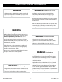
WARNING
WARNING: Installation and Service
Children and adults should be alerted to the hazards of
high surface temperature and should stay away to avoid
burns or clothing ignition.
Installation and Service must be performed by an
authorized qualified installer, service agency or gas
supplier.
Any alteration to the product that causes soot or carbon to
form and results in damage is not the responsibility of the
manufacturer.
ONLY an authorized qualified installer may open the door/
remove the glass. The end user must NOT open the door/
remove the glass, as this may be unsafe and may result in
voiding the manufacturer’s warranty.
WARNING
This direct vent system appliance must be installed as an
OEM installation in manufactured homes (USA only) or
an aftermarket permanently located, or a mobile home,
where not prohibited by local codes and must be
installed in accordance with Manufacturer’s instructions
and the Manufactured Home Construction and Safety
Standard, Title 24 CFR, Part 3280, in the United States, or
the Standard for Installation in Mobile Homes, CAN/CSA
Z240 MH Series, in Canada.
WARNING: Electrical Grounding
These direct vent appliances must be electrically
grounded in accordance with the local codes or, in the
absence of local codes, with National Electric code, ANSI/
NFPA 70, or the Canadian Electric Code, CSA C22.1
If the information in these instructions is not followed
exactly a fire or explosion may result causing property
damage, personal injury or death.
Do not store or use gasoline or other flammable vapors
and liquids in the vicinity of this appliance.
WARNING: Gas Appliance
This appliance is only for use with the type of gas
indicated on the rating plate. These appliances are not
convertible for use with other gases, unless a certified kit
is used and the conversion is performed by an authorized
qualified technician.
Applicable standards are ANSI Z21.50/CSA 2.22 (Vented
Gas Fireplaces) and CAN/CGA 2.17-M91 (Gas-fired
Appliances for Use at High Altitudes.) If your installation
is at an elevation greater than 2000’ in the US or 4500’
in Canada, consult with the local authority having
jurisdiction for gas product installations to determine their
specific requirements for high altitude installations.
WARNING: Glass Handling
The glass must only be removed by an authorized and/or
qualified installer. The authorized technician should only
remove the glass by the use of glass vacuum holders.
Element4 Gas Fireplaces
4
EuropeanHome.com
IMPORTANT SAFETY INFORMATION
This gas fireplace and vent assembly MUST be vented
directly to the outside and MUST NEVER be attached to a
chimney serving a separate solid fuel burning appliance.
Each gas appliance MUST BE a separate vent system.
Common vent systems are prohibited.
TURN OFF the gas before servicing the appliance. It is
recommended that a qualified service technician perform
an appliance check-up/service once a year.
This unit MUST be used with a vent system as described
in this installation manual. NO OTHER VENT SYSTEM OR
COMPONENTS MAY BE USED.
THIS UNIT IS NOT FOR USE WITH SOLID FUEL, and must
only be used with gas supply conditions as indicated on
the data label.
INSPECT the external vent cap on a regular basis to make
sure that no debris, plants, trees, shrubs are interfering
with the air flow.
DO NOT USE this appliance if any part has been under
water. Immediately call a qualified service technician to
inspect the unit and to replace any part of the control
system and any gas control that has been under water.
Any safety screen or guard removed for servicing MUST BE
REPLACED before operating this appliance.
DO NOT use this heater as a temporary source of heat
during construction.
NEVER OBSTRUCT the flow of ventilation air. Keep the
front of the appliance CLEAR of all obstacles and materials
for servicing and proper operation.
This appliance is a DOMESTIC ROOM HEATING APPLIANCE.
It must not be used for any other purposes such as drying
clothes, etc.
The glass panels MUST be in place and sealed before the
unit can be placed into safe operation.
If the pilot flame is extinguished either intentionally or
unintentionally, no attempt should be made to re-light the
gas until at least 3 minutes have elapsed.
DO NOT OPERATE this appliance with the glass panels
removed, cracked or broken. Replacement of the glass
panels should be performed by a licensed or qualified
service person. DO NOT strike or slam the glass panels.
The glass panels SHALL ONLY be replaced by units
supplied by the manufacturer. NO SUBSTITUTE panels
shall be used.
Dimensions will appear as
INCHES”/metric throughout this manual. For convenience,
the inches are rounded to the nearest 1/16” when
converted. If greater accuracy is required, use the metric
dimensions.
DO NOT USE abrasive cleaners on the panels. DO NOT
ATTEMPT to clean the glass panels when they are hot.
Element4 Gas Fireplaces
5
EuropeanHome.com
IMPORTANT SAFETY INFORMATION
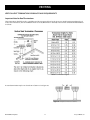
When enclosing your Element4 fireplace the use of non-combustible building materials is REQUIRED.
Please read and understand the following.
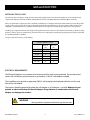
COMBUSTIBLE MATERIALS
Materials that can catch fire and burn are considered combustible. Any material that is made of, or faced with, wood, wood pulp,
paper, plastic or any other material that can catch fire and burn is considered combustible. Even though these materials may have
been 'flame-proofed', made 'fire-resistant' or are 'fire-rated' they are considered combustible. Standard and Type X drywall are
both combustible.
NON-COMBUSTIBLE MATERIALS
A given material is said to be non-combustible when it cannot catch fire and burn. For example, materials made entirely, or in
combinations, of, stone, brick, concrete, tile, steel, plaster or glass are considered non-combustible.
Table 1 shows a list of materials which, as of this writing, are reported by their manufacturers to be non-combustible (in
accordance with the ASTM E136 standard) AND approved for use around fireplaces. Products which have a YES in BOTH the Noncombustible and Manufacturer Approved columns can be used with this fireplace.
Product*
Non-combustible
Manufacturer Approved
James Hardie Building Products HardieBacker® 1/4” Cement Board
James Hardie Building Products HardieBacker® 500 Cement Board
Promat PROMATECT®-L Insulating Boards
Skamol Skamotec® 225
U.S. Architectural Products Versaroc® Cement Bonded Particle Board
U.S. Architectural Products Cem-Clad® Cement Panel
National Gypsum PermaBase® Cement Board
YES
YES
YES
YES
YES
YES
YES
YES
YES
YES
YES
YES
NO
NO
USG DUROCK® Cement Board Next Gen
YES
NO
CertainTeed Fiber Cement BackerBoard
NO
NO
Custom Building Products WonderBoard® Backerboard
Georgia-Pacific Gypsum DensGlass® Sheathing
NO
NO
YES
NO
Ameriform ARMOROC® Cement Bonded Particle Board
YES
NO
Table 1
* The listed brand names are trademarks of their respective companies
Element4 Gas Fireplaces
6
EuropeanHome.com
USER INFORMATION
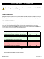
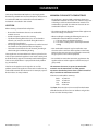
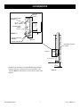
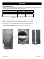
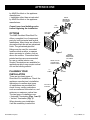
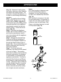
WARMTH AND BEAUTY - HOW IT WORKS
The Element4 fireplaces are called direct vent fireplaces and, as such, the intake and exhaust are both handled through the vent
pipe. The fireplace also provides convection air to your room. Figure 1 (below) shows one of the unique features of the Element4
fireplaces - its use of convection air flow.
Other fireplaces have louvered metal boxes around them to keep temperatures under control. The Element4 fireplaces use your
enclosing walls, or chase, to guide the convection air. This design, therefore, requires the use of non-combustible wall materials
and gives you beauty for your effort.
When the air within the chase is warmed by the fireplace it rises and exits through the Convection Air Outlet. This convection air
is replaced by room air which enters the chase through the Room Air Inlet. As the exiting convection air cools it falls to the floor
where it's drawn into the Inlet and the cycle repeats.
The fireplace itself provides the room air inlet as part of its design; you provide the convection air outlet as part of your design.
See the ENCLOSING the FIREPLACE section of this manual for more information.
Convection Air
Convection Air
Convection Air
Outlet (typical)
Chase
Room Air
Room Air Inlet
Figure 1
Element4 Gas Fireplaces
7
EuropeanHome.com
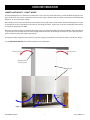
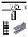
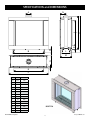
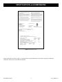
SPECIFICATIONS and DIMENSIONS
APPLIANCE RATINGS
Bidore 95
Modore 95
Trisore 95
Bioptica
Optica
Model
Gas
Bidore 100H
Modore 100H
Trisore 100H
Bidore 140, Lucius 140,
Lucius 140 T, Lucius
140 C 1/3, Lucius 140
C 2/3, Modore 140,
Trisore 140
Natural
Gas
Propane
Natural
Gas
Propane
Natural
Gas
Propane
Natural
Gas
Propane
Input Maximum
Btu/hr
30,730
26,300
36,200
32,400
34,145
34,145
38,200
34,100
Input Minimum
Btu/hr
17,070
8,535
17,050
13,650
15,025
17,075
13,650
11,950
Maximum Supply
Pressure
in. w.c.
7
11
7
11
7
11
7
11
kpa
1.74
2.74
1.74
2.74
1.74
2.74
1.74
2.74
Minimum Supply
Pressure
in. w.c.
4
8
4
8
4
8
4
8
kpa
1
2
1
2
1
2
1
2
Manifold Pressure
Maximum
in. w.c.
2.0
10.6
6.2
10.9
2.1
7.4
4.0
10.8
kpa
0.5
2.64
1.54
2.71
0.53
1.83
0.99
2.68
Manifold Pressure
Minimum
in. w.c.
0.8
1.4
1.5
2.1
1.5
9.5
0.4
1.5
kpa
0.2
0.34
0.39
0.52
0.38
2.28
0.1
0.38
Main Burner Injector Marking
1200
260
1200
380
650 (x2)
220 (x2)
1200
380
Pilot Injector Marking 31.2
27.1
31.2
27.1
31.2
27.1
31.2
27.1
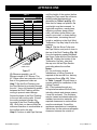
WALL ADAPTER SPECIFICATIONS
Input Voltage:
Input Power:
Output Voltage:
Output Current:
Size:
Output Cord Length:
Agency Approvals:
120V AC
9W
6V DC
500 mA
3.1”H x 2”W x 1.7”D
6 Feet
UL, CSA
Figure 2 Wall Adapter Connection (arrow)
Element4 Gas Fireplaces
8
EuropeanHome.com
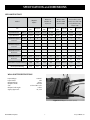
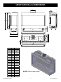
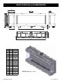
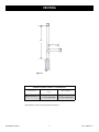
SPECIFICATIONS and DIMENSIONS
Letter
Inches
Millimeters
A
77/8
200
B
271/4
692
C
209/16
522
D
211/16
68
E
315/16
100
F
341/16
865
G
391/8
995
H
121/2
318
I
101/2
266
J
391/8
995
K
5/8
15
L
411/16
118
M
8
202
N
121/2
318
O
131/8
333
Element4 Gas Fireplaces
TRISORE 95 (GLASS 3 SIDES)
9
EuropeanHome.com
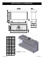
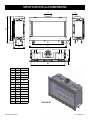
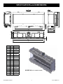
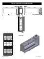
SPECIFICATIONS and DIMENSIONS
Letter
Inches
Millimeters
A
77/8
200
B
341/16
865
C
397/16
1001
D
37
949
E
397/16
1001
F
211/16
68
G
8
202
H
121/2
316
I
131/8
333
J
271/4
692
K
245/8
624
L
1611/16
424
M
315/16
100
N
101/2
266
O
121/2
318
P
5/8
15
Q
411/16
118
Element4 Gas Fireplaces
BIDORE 95 (RIGHT CORNER SHOWN)
10
EuropeanHome.com
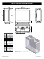
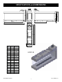
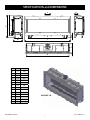
SPECIFICATIONS and DIMENSIONS
Letter
Inches
Millimeters
A
77/8
200
B
345/8
878
C
417/16
1052
D
211/16
68
E
371/2
952
F
5/8
15
G
121/2
316
H
281/8
714
I
257/16
646
J
1611/16
424
K
315/16
100
L
81/2
215
M
121/2
318
N
411/16
118
Element4 Gas Fireplaces
MODORE 95
11
EuropeanHome.com
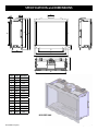
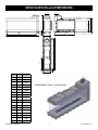
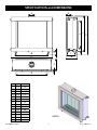
SPECIFICATIONS and DIMENSIONS
Letter
Inches
Millimeters
A
77/8
200
B
51/16
128
C
33
838
D
383/16
970
E
415/16
1050
F
155/8
398
G
415/16
1050
H
5/8
15
I
411/16
119
J
3511/16
899
K
38
964
L
39
990
M
135/16
337
N
2911/16
754
Element4 Gas Fireplaces
TRISORE 100H
12
EuropeanHome.com
SPECIFICATIONS and DIMENSIONS
Letter
Inches
Millimeters
A
77/8
200
B
51/16
128
C
33
838
D
383/16
970
E
415/8
1057
F
155/8
398
G
395/8
1005
H
5/8
15
I
411/16
119
J
3511/16
899
K
38
964
L
39
990
M
135/16
337
N
2911/16
754
BIDORE 100H (RIGHT CORNER SHOWN)
Element4 Gas Fireplaces
13
EuropeanHome.com
SPECIFICATIONS and DIMENSIONS
Letter
Inches
Millimeters
A
77/8
200
B
51/16
128
C
33
838
D
393/8
1000
E
431/2
1104
F
155/8
398
G
393/8
1000
H
5/8
15
I
411/16
119
J
3511/16
899
K
38
964
L
39
990
M
135/16
337
N
2911/16
754
MODORE 100H
Element4 Gas Fireplaces
14
EuropeanHome.com
SPECIFICATIONS and DIMENSIONS
Letter
Inches
Millimeters
A
77/8
200
B
503/4
1288
C
5711/16
1464
D
5/8
15
E
131/8
333
F
121/2
318
G
271/4
692
H
245/8
624
I
165/8
422
J
315/16
100
K
107/8
275
L
211/16
68
M
121/2
318
N
101/2
266
O
411/16
118
Element4 Gas Fireplaces
TRISORE 140 (GLASS 3 SIDES)
15
EuropeanHome.com
SPECIFICATIONS and DIMENSIONS
Letter
Inches
Millimeters
A
77/8
200
B
503/4
1288
C
5715/16
1471
D
211/16
68
E
557/8
1419
F
5715/16
1471
G
5/8
15
H
101/2
266
I
121/2
318
J
411/16
118
K
165/8
422
L
245/8
624
M
271/4
692
N
315/16
100
O
107/8
275
P
121/2
318
Q
131/8
333
Element4 Gas Fireplaces
BIDORE 140 (LEFT CORNER SHOWN)
16
EuropeanHome.com
SPECIFICATIONS and DIMENSIONS
Letter
Inches
Millimeters
A
77/8
200
B
143/8
364
C
3213/16
834
D
5411/16
1389
E
607/16
1534
F
5515/16
1420
G
5711/16
1464
H
147/16
366
I
36
915
J
213/16
70
K
4
102
L
165/8
422
M
2411/16
626
N
277/16
696
O
71/16
180
P
5/8
15
Element4 Gas Fireplaces
LUCIUS 140
17
EuropeanHome.com
SPECIFICATIONS and DIMENSIONS
Letter
Inches
Millimeters
A
77/8
200
B
143/8
364
C
143/8
364
D
221/2
570
E
201/2
520
F
577/8
1470
G
5515/16
1420
H
5/8
15
I
213/16
70
J
3213/16
834
K
5411/16
1389
L
607/16
1534
M
371/2
953
N
4
102
O
165/8
422
P
2411/16
626
Q
277/16
696
R
71/8
180
Element4 Gas Fireplaces
LUCIUS 140 C 1/3 (RIGHT CORNER SHOWN)
18
EuropeanHome.com
SPECIFICATIONS and DIMENSIONS
Letter
Inches
Millimeters
A
77/8
200
B
143/8
364
C
143/8
364
D
393/8
1000
E
377/16
950
F
577/8
1470
G
5515/16
1420
H
5/8
15
I
213/16
70
J
3213/16
834
K
5411/16
1389
L
607/16
1534
M
371/2
953
N
4
102
O
165/8
422
P
2411/16
626
Q
277/16
696
R
71/8
180
Element4 Gas Fireplaces
LUCIUS 140 C 2/3 (RIGHT CORNER SHOWN)
19
EuropeanHome.com
SPECIFICATIONS and DIMENSIONS
Letter
Inches
Millimeters
A
77/8
200
B
143/8
364
C
143/8
364
D
597/16
1509
E
551/2
1409
F
597/16
1509
G
551/2
1409
H
5/8
15
I
213/16
70
J
3213/16
834
K
5315/16
1370
L
613/16
1554
M
371/2
953
N
4
102
O
165/8
422
P
2411/16
626
Q
277/16
696
R
71/8
180
Element4 Gas Fireplaces
LUCIUS 140 T
20
EuropeanHome.com
SPECIFICATIONS and DIMENSIONS
Letter
Inches
Millimeters
A
77/8
200
B
345/8
1288
C
5913/16
1518
D
211/16
68
E
557/8
1418
F
5/8
15
G
121/2
316
H
281/8
714
I
257/16
646
J
1611/16
424
K
315/16
100
L
107/8
275
M
121/2
318
N
411/16
118
Element4 Gas Fireplaces
MODORE 140
21
EuropeanHome.com
SPECIFICATIONS and DIMENSIONS
Letter
Inches
Millimeters
A
515/16
150
B
341/4
869
C
4211/16
1084
D
213/16
71
E
321/16
814
F
5/8
15
115/8
321⁄16"/ 814
3713/16
mm
295
961
I
35
889
J
261/2
672
K
313/16
96
L
87/8
224
M
1111/16
297
N
57/16
138
Element4 Gas Fireplaces
42 ⁄16"/ 1084 mm
8"/ 203 mm
11
OPTICA
22
8 mm
G
H
1111⁄16"/ 297 mm
mm
101⁄16"/ 255 mm
90
°
393⁄8"/ 1000
57⁄16"
65⁄16"
127.5 mm 160 mm
???7⁄16"
EuropeanHome.com
SPECIFICATIONS and DIMENSIONS
Millimeters
A
515/16
150
B
341/4
869
mm
mm
C
4211/16
1084
D
213/16
71
E
321/16
814
129⁄16"/ 319
Letter
F
5/8
15
G
115/8
319
mm
3713/16
961
321⁄16"/ 814
H
I
35
889
J
261/2
672
K
313/16
96
L
87/8
224
M
129/16
319
N
65/16
160
Element4 Gas Fireplaces
4211⁄16"/ 1084
mm
BIOPTICA
23
mm
Inches
101⁄16"/ 255
57⁄16"
65⁄16"
160 mm
EuropeanHome.com
SPECIFICATIONS and DIMENSIONS
DO NOT REMOVE
NE PAS RETIRER
DIRECT VENT GAS FIREPLACE - Not for
use with solid fuel.
FOYER GAZ À AÉRATION DIRECTE - Ne pas
utiliser avec un combustible solide
This appliance is only for use with the type of gas indicated on the
rating plate and may be installed in an aftermarket, permanently
located, manufactured home (USA only) or mobile home where
not prohibited by local codes. See owner’s manual for details. This
appliance is not convertible for use with other gases, unless a
certified kit is used.
Cet appareil est destiné uniquement avec le type de gaz indiqué sur
la plaque signalétique et peut être installé dans une habitation en dur,
à emplacement fixe (USA uniquement) ou dans une résidence mobile
si la législation locale l’autorise. Consultez le manuel du propriétaire
pour les détails. Cet appareil ne doit pas être modifié pour une utilisation avec d’autres gaz, sauf à l’aide d’un kit certifié.
For use only with Vent, Glass Panels and Ceramic Logs (or
stones) certified and approved for use with this appliance.
À utiliser uniquement avec des ventilations, panneaux en verre et
poutres (ou pierres) en céramique dont l’utilisation est autorisée avec
cet appareil.
This appliance must be installed in accordance with local codes,
if any; if none, follow ANSI Z223.1/NFPA 54, or CSA B149.1. The
appliance must be properly connected to a venting system in accordance with the manufacturer’s installation instructions.
The system must be installed by ba qualified installing agency.
Cet appareil doit être installé conformément à la législation locale. À
défaut d’une telle législation, suivre ANSI Z223.1/NFPA 54, ou CSA
B149.1. L’appareil doit être proprement raccordé à un système de
ventilation, conformément aux instructions d’installation du fabricant.
Le système doit être installé par un installateur qualifié.
Manufacturer/ Fabricant:
Element4 B.V.
Paxtonstraar 23
NL-8013 RP Zwolle
The Netherlands / Pays-Bas
Tel / Tél : 0031 38 4209020
Fax:0031 38 4209021
Approved By / Approuvé par:
Control No. : 4006611
Conforms to std.
Certified to std.
Product name: (check one) / Nom du produit : (cochez …)
Trisore 100H
[
]
Bidore 100H
[
Modore 100H
[
]
ANS Z21.50a-2008
CSA 2.22a-2008 - Vented Gas Fireplaces
]
Serial No. / N° de série: _____________
This appliance equipped only for altitudes /
Cet appareil est équipé uniquement pour les altitudes : 0-4500 ft / 0-1370 m
Fuel Type / Type de combustible
(check one) / (cochez…)
Max. Input / Capacité d’entrée maxi (BTU/HR)
Min. Input / Capacité d’entrée mini (BTU/HR)
Gas Inlet Pressure (in w.c.) / Pression d’entrée du gaz (en w.c.)
Manifold Pressure (in w.c.) / Pression d’admission (en w.c.)
Orifice Size / Taille de l’ouverture
Natural Gas /
Gaz naturel
[
]
34145
15025
7
2.1
650 (x2)
Propane Gas /
Gaz propane
[
]
34145
17075
11
7.4
180 (x2)
Clearances to combustible / Dégagement jusqu’au combustible :
Back / Arrière : 11” (28cm)
Sides / Côtés : 11” (28cm)
Top / Haut
: 26” (66cm)
Floor / Sol
: 4” (10cm)
Mantel / Linteau : 2” (5cm)
Figure 3. Typical Rating Label
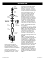
A typical rating label is shown in Figure 3. It is attached to every Element4 fireplace and contains important certification
information. It must not be removed from the fireplace.
Element4 Gas Fireplaces
24
EuropeanHome.com
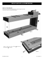
SPECIFICATIONS and DIMENSIONS
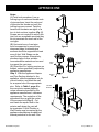
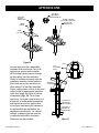
PARTS OF THE FIREPLACE
The various parts of the Lucius 140 fireplace are shown in Figures 4, 5 and 6.
These parts are typical of any Element4 fireplace.
11
9
1
8
2
6
3
7
8
5
4
1
10
8
Figure 4
3
8
1
5
4
Figure 5 shows two Glass Clamps, 10 after some of
the Finish Trim 8 is removed.
1
10
Element4 Gas Fireplaces
25
Figure 5
EuropeanHome.com
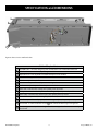
SPECIFICATIONS and DIMENSIONS
10
2
1
13
14
12
3
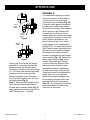
Figure 6
Figure 6 shows a Lucius 140 from below.
Table of Fireplace Parts
1
2
3
4
5
6
7
8
9
10
11
12
Standoff Frame - surrounds the glass panels and limits the non-combustible wall board
Glass Panel - one, two or three, depending on model
Adjustable Foot - four adjustable feet allow the fireplace to be levelled
Hearth Panel - supports various Fire Media
Main Burner - produces the flame
Pilot Burner - the part of the safety circuit which lights the Main Burner
2nd Thermocouple - the part of the safety circuit which monitors the Main Burner
Finish Trim - hides the Glass Clamps, the quantity varies by model
Fixing Bracket - attaches the fireplace to the building, the quantity varies by model
Glass Clamp - holds the Glass Panel in place, the quantity varies by model
Vent Collar - accepts the 5”/8” venting adapter (included)
Relief Door - part of the safety system, do not change or adjust, the quantity varies by model
13 Gas Control - is at the end of the Line Set 14 and controls the flow of gas. See Figure 57.
Line Set - approximately 51”/1.3 m long and is to be unwrapped to allow remote mounting of
14 Gas Control
Table 2.
Element4 Gas Fireplaces
26
EuropeanHome.com
CLEARANCES
MINIMUM CLEARANCE TO COMBUSTIBLES
The beauty of the Element4 fireplaces is due largely to the
fact that they are NOT zero-clearance fireplaces. All clearances
to combustible AND non-combustible materials MUST be
maintained as described in this manual.
•The appliance is approved with a minimum clearance to
combustible materials on all sides of 11”/280 mm. Any spacer
or framing used closer than this dimension must be noncombustible (e.g. metal). The minimum clearance to noncombustible material is 2”/50 mm.
LOCATION
When selecting a location for the fireplace:
•The minimum distance from the bottom of the appliance to
the room ceiling is 72”/1830 mm.
• Ensure that all minimum clearances to combustible
materials are met.
• Provide adequate clearances for servicing.
• The allowed venting dimensions (rise, run and number
of bends, etc.) must be considered during the location
selection for your fireplace.
• Due to high temperatures, the appliance should be located
out of traffic and away from furniture and draperies.
• The location should also be free of electrical, plumbing or
other heating/air conditioning ducting.
•When installing the venting the following clearances to
combustible materials MUST be maintained:
a. 3”/76 mm above any horizontal venting
b. 1”/25 mm to venting sides or below any horizontal
venting
•Non-combustible materials may be installed to a zero
clearance to the outer faces of the appliance outer frame.
However, they must not cover (or prevent the removal of)
the glass panels or the control equipment.
These appliances are intended to be built in to a place for fire.
The base upon which the appliance rests must be sturdy, level
and built to safely support at least 500 pounds/230 kilograms.
The base may be the floor or a purpose built raised platform
(e.g. wood,metal).
•Do not block or restrict the convection gap between the
appliance firebox and the appliance outer frame (top of
glass panels).
The minimum clearances (air spaces) to combustible
materials must be maintained. It is of the greatest
importance that the fireplace and vent system be installed
only in accordance with these instructions.
The feet on the appliance are designed to sit on a flat
platform, however the appliance must not be installed on any
combustible material other than wood. For example, carpet or
linoleum bases are not permitted.
Clearance to combustibles summary:
Back:11”/280 mm
Sides:11”/280 mm
Top:26”/660 mm
Floor:4”/100 mm
The Floor dimension (above) is measured from the bottom
of the firebox thus the feet can sit on the floor and give this
clearance in their lowest position.
Element4 Gas Fireplaces
27
EuropeanHome.com
A
VENT OPENING
800cm² (124In²)
TOTAL MINIMUM
CLEARANCES
CTION A-A
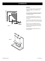
MANTELS
The graph in Figure 7 shows a range of allowable
depths and heights for a combustible mantel
installation.
INCHES 20 18 16 14 12 10 8 6 4 2 0
20
Mantel Depth
Depth
Mantel
18
(12) 300
12”/300
mm
16
C
14
12
8
6
4
2
A
B
MantelHeight
Height
Mantel
13”/330
mm
(13) 330
10
The maximum mantel depth is 12”/300 mm at a
minimum height above the fireplace opening of
13”/330 mm.
SECTION A-A
0
(36")
900
2”/50(2)mm
50
CTION B-B
As shown, the minimum allowable mantel height
above the fireplace opening is 2”/50 mm with a
1”/25 mm deep mantel.
25
1”/25(1)mm
All of the mantel height/depth combinations fall in
between these extremes in accordance with Figure
12.
(2") 50
GLASS
TOP OF
FIREPLACE
OPENING
COMBUSTIBLE MATERIALS
NOT PERMITTED IN FRONT
OF GLASS
A typical completed installation with mantel is
shown in Figure 8.
(36")
900
Figure 7
Mantels made of non-combustible material are
allowed inside these dimensions but they will be
subjected to elevated temperatures and may be
too hot to touch.
CONSTRUCTION
BEAMS COMBUSTIBLE
(TYPICAL)
(2")
50
(11")
280
Figure 8
GLASS
Element4 Gas Fireplaces
28
EuropeanHome.com
1”
1"
25 (25)
mm
2”
2"
50 (50)
mm
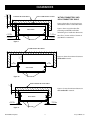
CLEARANCES
COMBUSTIBLE MATERIAL
NON-COMBUSTIBLE LINING
WITHIN COMBUSTIBLE AND
NON-COMBUSTIBLE WALLS
Figures 9 through 11 show clearances to
Combustible
Material
combustible
and non-combustible walls.
with a Non-Combustible
Lining
Figure 9 shows a typical method for
protecting combustible walls while
maintaining close installation dimensions.
APPLIANCE
1”/25
mm
1" (25)
1"1”/25
(25)mm
2”/50
mm
2" (50)
2”/50
mm
2" (50)
GLASS
Note: The 1”/25 mm and the 2”/50 mm air
gaps MUST be maintained.
Figure 9
COMBUSTIBLE MATERIAL
11"
11”
280
mm
(280)
Figure 10 shows the minimum distance to
combustible materials.
Combustible Material
11”
11"
280
mm
(280)
11”
11"
280
mm
(280)
APPLIANCE
Figure 10
GLASS
2”
2"50(50)
mm
NON-COMBUSTIBLE MATERIAL
Figure 11 shows the minimum distance to
non-combustible materials.
Non-Combustible
Material
APPLIANCE
2”/50
2"
(50)mm
2”/50
mm
2" (50)
Figure 11
Element4 Gas Fireplaces
GLASS
29
EuropeanHome.com
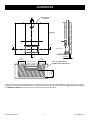
CLEARANCES
A
WARMOPENING
AIR OUTLET
VENT
800cm²
(124In²)
REQUIRED
TOTAL MINIMUM
Figure 12
C
B
B
SECTION A-A
A
(36")
36”
900
mm
900
SECTION B-B
2”/50
(2")mm
50
(36")
36”
900900
mm
KEEP THIS AREA FREE OF
COMBUSTIBLE FURNISHINGS
MATERIALS
COMBUSTIBLE
NOT PERMITTED IN FRONT
36”
(36")
900
mm
900
OF GLASS
CONSTRUCTION
BEAMS COMBUSTIBLE
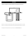
A typical chase enclosing a Trisore fireplace (as an example) is(TYPICAL)
shown in Figure 12. Section B-B (plan view) shows the area around
the fireplace in which combustible furnishings are not permitted. Section A-A shows the clearance to NON-combustible materials.
NON COMBUSTIBLE
See ENCLOSING the FIREPLACE
for the dimensions required for the Convection Air Outlet.
CONSTRUCTION
BEAMS NONCOMBUSTIBLE
(TYPICAL)
(2")
50
(11")
280
MATERIAL
DETAIL C
TOP OF FIREPLACE
OPENING
CONVECTION GAP
Element4 Gas Fireplaces
GLASS
30
EuropeanHome.com
(36")
900
CLEARANCES
CONSTRUCTION
NON-COMBUSTIBLE
BEAMS COMBUSTIBLE
FRAMING
(TYPICAL)
(TYPICAL)
CONSTRUCTION
NON-COMBUSTIBLE
BEAMS
NONFRAMING
COMBUSTIBLE
(TYPICAL) (TYPICAL)
(2")2”
50 mm
50
(11")
280
NON COMBUSTIBLE
MATERIAL
A
DETAIL
“C”
DETAIL C
TOP OF FIREPLACE
OPENING
VENT OPENING
800cm² (124In²)
TOTAL MINIMUM
GLASS
CONVECTION GAP
NON-COMBUSTIBLE WALL
(TYPICAL)
DETAIL “C”C
B
B
SECTION A-A
2”
(2")mm
50
50
A
(36")
(36")
Figure 13
COMBUSTIBLE MATERIALS
NOT PERMITTED IN FRONT
OF GLASS
(36")
900
Detail C shows
900how the non-combustible framing
900above the
fireplace maintains a minimum
clearance
of
2”/50
mm. This
SECTION B-B
clearance MUST be maintained to ensure safe operation of the
fireplace.
CONSTRUCTION
BEAMS COMBUSTIBLE
(TYPICAL)
CONSTRUCTION
BEAMS NONElement4 Gas Fireplaces
COMBUSTIBLE
(TYPICAL)
(2")
50
(11")
280
NON COMBUSTIBLE
MATERIAL
31
EuropeanHome.com
CLEARANCES
TYPICAL CLEARANCE DIAGRAMS
The total area of the convection air outlet(s) depends on the fireplace model. (See Table 7 on page 47.) The location of the outlet(s)
must allow for the free movement of air and must not allow excessive convection air to build up within the chase. The top of the
outlet(s) must be at least 1”/25 mm down from the ceiling and we recommend no more than 6”/152 mm down.
The minimum distance from the bottom of the appliance to the room ceiling is 72”/1830 mm. See Table 3.
B
A
Convection
Air Outlet
Minimum Distances
A
Room ceiling to
appliance bottom
72”
1830 mm
B
Room ceiling to top of
Convection Air Outlet
1”
25 mm
Table 3
Figure 14.
Element4 Gas Fireplaces
32
EuropeanHome.com
GAS and ELECTRIC
INSTALLING THE GAS LINE
Correctly size and route the gas supply line from the supply regulator to the area where the appliance is to be installed as per
requirements outlined in the latest edition of the National Fuel Gas Code, NFPA 54 (USA) or CAN/CSA-B149.1 (Canada).
Never use galvanized or plastic pipe unless specified specifically for use with gas. Refer to the table below for proper sizing of the
supply gas line. Gas lines must be routed, constructed and made of materials that are in strict accordance with local codes and
regulations. A qualified plumber or gas fitter should be hired to correctly size and route the gas supply line to the appliance.
Installing a gas supply line from the fuel supply to the appliance involves numerous considerations of materials, protection, sizing,
locations, controls, pressure, sediment trap, and other criteria. The sizing and/or installing of gas piping should only be performed
by a qualified plumber or gasfitter.
The gas control inlet accepts a 3/8” NPT fitting.
Schedule 40 Black Iron Pipe
Natural
Gas
Length (feet)
Propane
Gas
Inside Diameter (Inches)
0 - 10
1/2
3/8
10 - 40
1/2
1/2
40 - 100
1/2
1/2
100 - 150
3/4
1/2
150 - 200
3/4
1/2
Table 4
ELECTRICAL REQUIREMENTS
The Element4 fireplaces use a receiver and remote control for their burner operation. The remote control
comes with a 9V battery and the receiver is powered by a 120V AC wall adapter, included.
This installation must provide an approved 120V AC wall receptacle to be placed within the six foot cord
limit of the wall adapter.
The receiver should be powered by either the wall adapter or 4AA batteries - not both. Batteries do not
provide an electrical backup for the wall adapter. Using batteries in combination with the wall
adapter can damage the receiver.
WARNING
Element4 Gas Fireplaces
Electrical work must be performed by a qualified, licensed electrician.
All wiring shall be in compliance with all local, city, and state codes.
33
EuropeanHome.com
VENTING
CONFIGURING THE VENTING
The fireplaces in this manual are direct vent fireplaces that uses a co-axial or “pipe within a pipe” venting system. The outer “pipe”
or vent conducts fresh, outside air into the fireplace and the inner vent carries the exhaust outside. This technology, which can run
either horizontally through a side wall or vertically through the roof, produces an efficient system because conditioned building
air is not used for combustion.
NOTE: The Optica and Bioptica fireplaces use 4”/65/8” venting.
Bidore, Lucius, Modore and Trisore models use 5”/8” venting.
All of the following points apply to every installation:
•
Only the direct vent components from M&G DuraVent (listed in Table 5) are approved for use with these fireplaces. The
installation instructions are in Appendix One. Please read, understand and follow these instructions.
•
Every Element4 fireplace is shipped with a North American venting adapter. It MUST be the first piece of venting installed.
•
All measurements are taken from the center of the vent connector on the top of the fireplace (see Figure 15) and all
configurations must fall within the acceptable range of the model-specific diagrams.
•
The maximum allowable rise is 36’/11.0 m and the maximum allowable run is 16’4”/5.0 m but not in combination; see modelspecific diagrams.
•
Optica/Bioptica - The minimum vent configuration is a 3’3”/1.0 m vertical rise to a 90° elbow plus a 19”/500 mm horizontal run
to a wall termination.
All other models - The minimum vent configuration is a 19”/500 mm vertical rise to a 90° elbow plus a 19”/500 mm horizontal
run to a wall termination.
•
When using wall terminations no more than two horizontal 45° or 90° elbows are allowed. See model-specific diagrams.
•
When using vertical terminations no more than four 90° elbows OR eight 45° elbows OR a combination totaling no more
than 360° ‘elbow degrees’. For example, a combination of two 90° elbows and two 45° elbows is allowed (90° + 90° + 45°+ 45°
equals 270°) but a combination of three 90° elbows and three 45° elbows is not allowed (the total equals 405°.) These elbows
can be installed either horizontally or vertically.
•
A minimum clearance of 3”/75 mm must be maintained between combustible materials and the top of any horizontal vent
pipe surface; a minimum clearance of 1”/25 mm must be maintained between combustible materials and any other vent pipe
surface.
•
The horizontal parts of the venting must be pitched up, away from the fireplace. For every 12”/305 mm of horizontal run, the
venting must rise 1/4”/6.5 mm toward the termination. The venting must never run downward.
•
Whenever venting passes through a wall, a heat shield, or ‘wall thimble’ from the manufacturer listed in Table 5 must be
installed.
Element4 Gas Fireplaces
34
EuropeanHome.com
VENTING
rise
run
Figure 15
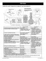
APPROVED MANUFACTURERS and COMPONENTS
Manufacturer
All Bidore, Lucius, Modore,
Trisore
Optica, Bioptica
M&G DuraVent, Inc.*
only DirectVent Pro
5” x 8” components
only DirectVent Pro
4” x 65/8” components
Table 5
* Appendix One contains venting installation instructions.
Element4 Gas Fireplaces
35
EuropeanHome.com
VENTING
HORIZONTAL TERMINATION DIAGRAM FOR BIDORE, LUCIUS, MODORE AND TRISORE ONLY
V
H
Distance “H” = 0.5-5m (min - max)
Distance “V” = 0.5-3m (min - max)
Note - for E4-10 & 11 Elbow can go
on to fire, thus “V” min = 200mm
Note2 - For E4-5, use a 50mm flue
Restrictor
Figure 16
Dimension “H” can vary between 19”/500 mm minimum to 16’4”/5.0 m maximum depending on Dimension “V”. See Graph 1.
Dimension “V” can vary between 19”/500 mm minimum to 9’10”/3.0 m maximum depending on Dimension “H”. See Graph 1.
Note: Configurations with horizontal terminations may need a restrictor. See the INSTALLING A RESTRICTOR section.
Element4 Gas Fireplaces
36
EuropeanHome.com
VENTING
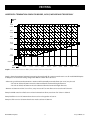
HORIZONTAL TERMINATION GRAPH FOR BIDORE, LUCIUS, MODORE AND TRISORE ONLY
Vertical
Rise
V (METRES)
9’10”
3.0
2.5
2.0
1.5
1.0
0.5
3.0 m
8’2”
2.5 m
6’6”
2.0 m
4’11”
1.5 m
3’3”
1.0 m
1’7”
0.5 m
Maximum pipe extension, for outside wall.
Use shaded area to calculate maximum
alowable length (H) for the corresponding
pipe rise (V).
0”/0 mm
H
Horizontal
Run
0
(METRES)
1’7”
0.5 m
0.5
3’3”
1.0 m
1.0
4’11”
1.5 m
1.5
6’6”
2.0 m
8’2”
2.5 m
2.0
2.5
Graph 1. Horizontal Terminations on Bidore, Lucius, Modore and Trisore models ONLY
9’10”
3.0 m
3.0
11’5”
3.5 m
13’1”
4.0 m
3.5
4.0
14’9”
4.5 m
16’4”
5.0 m
4.5
5.0
Graph 1 shows the maximum horizontal vent run (to the outside wall) for a certain vertical vent rise on all models EXCEPT Optica
and Bioptica. The allowable venting configuration MUST be within the shaded area.
• When using a wall-mounted termination a maximum of 2 horizontally-mounted elbows (45° or 90°) may be used.
- For each 45° elbow, 20”/500 mm must be subtracted from the horizontal length allowance.
- For each 90° elbow, 40”/1000 mm must be subtracted from the horizontal length allowance.
• Between 19”/500 mm and 4’11”/1.5 m of rise, every increase of 1”/25 mm allows an increased run of 4”/100 mm.
Example A: With a total rise of 60”/1.52 m and one horizontal 90° elbow, a total run of 13’1”/4.0 m is allowed
Example B: If the rise is 3’10”/1168 mm then the run can be no longer than 12’/3.67 m.
Example C: If the run is 5’ 6”/1.68 m then the rise must be at least 2’2”/670 mm.
Element4 Gas Fireplaces
37
EuropeanHome.com
VENTING
HORIZONTAL TERMINATION DIAGRAM FOR OPTICA AND BIOPTICA ONLY
V
H
Distance “H” = 0.5-5m (min - max)
Distance “V” = 0.5-3m (min - max)
Note - for E4-10 & 11 Elbow can go
on to fire, thus “V” min = 200mm
Note2 - For E4-5, use a 50mm flue
Restrictor
Figure 17
Dimension “H” can vary between 19”/500 mm minimum to 16’4”/5.0 m maximum depending on Dimension “V”. See Graph 2.
Dimension “V” can vary between 3’3”/1.0 m minimum to 9’10”/3.0 m maximum depending on Dimension “H”. See Graph 2.
Note: Configurations with horizontal terminations may need a restrictor. See the INSTALLING A RESTRICTOR section.
Element4 Gas Fireplaces
38
EuropeanHome.com
VENTING
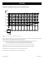
HORIZONTAL TERMINATION GRAPH FOR OPTICA AND BIOPTICA ONLY
Vertical
Rise
V (METRES)
9’10”
3.0
2.5
2.0
1.5
1.0
3.0 m
8’2”
2.5 m
6’6”
2.0 m
4’11”
1.5 m
3’3”
1.0 m
3’3”
1.0 m
4’11”
1.5 m
Maximum pipe extension, for outside wall.
Use shaded area to calculate maximum
alowable length (H) for the corresponding
6’6”
8’2”
9’10”
11’5” 13’1”
14’9”
16’4”
risem(V).3.0 m
2.0 mpipe 2.5
3.5 m 4.0 m
4.5 m
5.0 m
1.0
1.5
2.0
0.5
1’7”
0.5 m
0”/0 mm
Horizontal
(METRES) Run 0
H (METRES)
0
0.5
2.5
3.0
3.5
4.0
4.5
5.0
Graph 2. Horizontal Terminations on Optica and Bioptica models ONLY
Graph 2 shows the maximum horizontal vent run (to the outside wall) for a certain vertical vent rise on Optica and Bioptica models
ONLY. The allowable venting configuration MUST be within the shaded area.
• When using a wall-mounted termination a maximum of 2 horizontally-mounted elbows (45° or 90°) may be used.
- For each 45° elbow, 20”/500 mm must be subtracted from the horizontal length allowance.
- For each 90° elbow, 40”/1000 mm must be subtracted from the horizontal length allowance.
• Between 3’3”/1.0 m and 4’11”/1.5 m of rise, every increase of 1”/25 mm allows an increased run of 4”/100 mm.
Example A: With a total rise of 60”/1.52 m and one horizontal 90° elbow, a total run of 13’1”/4.0 m is allowed
Example B: If the rise is 3’10”/1168 mm then the run can be no longer than 12’/3.67 m.
Example C: If the run is 5’ 6”/1.68 m then the rise must be at least 2’2”/670 mm.
Element4 Gas Fireplaces
39
EuropeanHome.com
VENTING
HORIZONTAL VENT TERMINATION CLEARANCES AND REQUIREMENTS
Element4 Gas Fireplaces
40
EuropeanHome.com
VENTING
V
12”/304 mm
150
min
minimum
12”/304 mm
minimum
150 min
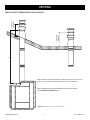
VERTICAL VENT TERMINATIONS FOR ALL MODELS
When installing vertical venting with no elbows, dimension “V” must be at
least 3’3”/1.0 m minimum and no more than 36’/11.0 m maximum.
Distance "V" 1m - 11m (min - max)
Note: Configurations with vertical terminations may need a restrictor.
See the INSTALLING A RESTRICTOR section.
Figure 18. Vertical Terminations with NO elbows
Element4 Gas Fireplaces
41
EuropeanHome.com
VENTING
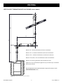
V2
VERTICAL VENT TERMINATIONS WITH 90° ELBOWS (FOR ALL MODELS)
V
H
V1
Distance “H” = 0”/0.0 m minimum to 9’10”/3.0 m maximum
Distance “V1” = 19”/500 mm minimum to 33’10”/10.0 m maximum
Distance “V2” = 19”/500 mm minimum to 33’10”/10.0 m maximum
Distance “V” (V1+V2) = 3’3”/1.0 m minimum to 36’/11.0 m maximum
Distance “V” must be greater than twice the distance of “H”
Distance
"H" =m0of- maximum
3m (min -height
max) for every 90° elbow up to a maximum
Subtract
3’3”/1.0
Distance "V1" = 500mm - 10m (min - max)
of four
(4) 90°"V2"
elbows.
Distance
= 500mm - 10m (min - max)
Distance "V" (= V1+V2) = 1m - 11m
(min - max)
Note: Configurations with vertical terminations may need a restrictor. See the
Distance "V" =2x "H" (min)
INSTALLING A RESTRICTOR section.
Figure 19. Vertical Terminations with 90° elbows
Element4 Gas Fireplaces
42
EuropeanHome.com
VENTING
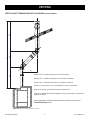
V2
V
V3
VERTICAL VENT TERMINATIONS WITH 45° ELBOWS (FOR ALL MODELS)
H
V1
Distance “H” = 0”/0.0 m minimum to 9’10”/3.0 m maximum
Distance “V1” = 19”/500 mm minimum to 33’10”/10.0 m maximum
Distance “V2” = 8”/200 mm minimum to 33’10”/10.0 m maximum
Distance “V” (V1+V2+V3) = 3’11”/1.2 m minimum to 36’/11.0 m maximum
Distance
= 0be
- 3m
(minthan
- max)
Distance
“V”"H"
must
greater
twice the distance of “H”
Distance "V1" = 500mm - 10m (min - max)
Distance
"V2" =mm
200mm
- 10m (min
- max)
Subtract
19”/500
of maximum
height
for every 45° elbow up to a maximum of
Distance "V3" = 500mm - 10m (min - max)
eight
(8)
45°
elbows.
Distance "V" (= V1+V2+V3) = 1.2m - 11m
(min - max)
Distance
"V" =2x "H"
Note:
Configurations
with(min)
horizontal terminations may need a restrictor. See the
INSTALLING A RESTRICTOR section.
Figure 20. Vertical Terminations with 45° elbows
Element4 Gas Fireplaces
43
EuropeanHome.com
VENTING
VERTICAL VENT TERMINATION CLEARANCES AND REQUIREMENTS
Important Note for Roof Terminations
These instructions should be used as a guideline and do not supersede local codes in any way. Install venting according to local
codes, these instructions, the current National Fuel Gas Code (ANSI Z223.1 in the USA) or the current standard of CAN/CSA-B149.1
in Canada.
Chart 1. Termination Heights
A second termination may be no closer than 12”/305 mm. See Figure 36.
Figure 21. Multiple Termination Clearance
Element4 Gas Fireplaces
44
EuropeanHome.com
VENTING
INSTALLING A RESTRICTOR
As previously noted, restrictors must be fitted in some configurations. Use the table below to determine which restrictor may be
needed with your venting configuration. The restrictors are shown in Figure 24.
When Using a Horizontal
(Wall) Termination
When vertical section is up to 391/2”/1 m no restrictor required
When vertical section is 391/2”/1 m to 9’10”/3 m 35 mm restrictor
When Using a Vertical
(Roof) Termination
n/a
n/a
When rise is up to 6’6”/2 m n/a
35 mm
When rise is above 6’6”/2 m n/a
60 mm
Table 6. Restrictors by Vent Configuration
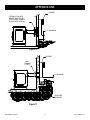
Note: On Lucius models only, the bottom of the outlet collar is above, and hidden by, a baffle. The baffle is attached to the inside top of
the fireplace as shown in Figure 22. The baffle must first be removed before the restrictor can be installed. Remove the eight attachment
bolts. There are two at either end of the baffle and four in the middle. The center four are shown in Figure 22.
A restrictor for all fireplace models installs in the same location; at the very bottom of the outlet collar.
- Attach the appropriate restrictor to the bottom of the outlet collar as shown in Figure 23.
- Re-attach the baffle on Lucius models
Attachment
bolts (4 of 8)
holding the
Lucius baffle
in place.
35 mm
Figure 23
60 mm
Figure 24
Figure 22
Element4 Gas Fireplaces
45
EuropeanHome.com
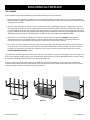
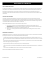
ENCLOSING the FIREPLACE
THE FRAMING
A safe installation of your Element4 fireplace requires that four things be clearly understood.
1.Most important, these fireplaces are NOT zero-clearance fireplaces. Unlike most others, there is not a metal box around the
Element4 fireplaces. With no metal box there are no louvers to distract your view of the fire. We do, however, want the cooling
advantage of a metal box.
2.This means that your fireplace enclosure must be made to act the way a metal fireplace box acts - letting room air in below
and convection air out above. The non-combustible framing cannot interfere with the air flow. The inlets for the room air are
part of the fireplace and cannot be changed or adjusted. See Figure 1. The outlet is part of your enclosure design, is provided
by you and MUST be included. Note: The Convection Air Outlet must be installed in the same room as the fireplace or a room which
ALWAYS flows air into the room in which the fireplace is installed. The flow of convection air must NOT be blocked.
3.Since these are not zero-clearance fireplaces, the clearances and dimensions listed in the CLEARANCES section MUST be
maintained. Only the non-combustible wall board, the mounting brackets and the venting may touch the fireplace. As
previously stated, non-combustible framing must be used and may be no closer than 2”/50 mm.
4.The controls are not mounted on the fireplace, they are to be mounted to your framing and below the burner. The controls
are at the end of a 50”/1270 mm line set and are to be mounted to the BDLE4 Access Door, included. The controls must be
located for ease of physical access (gas line, maintenance, etc.) as well as wireless signal (remote control) access. See the
LOCATING AND MOUNTING THE CONTROLS section.
The combination of multiple glass sides and no zero-clearance box makes for a non-typical framing project. As seen in Figures 2527, it is easy to build the ‘rough opening’, set the fireplace then attach the wall. For projects with tight clearances, however, it may
be easier to set the fireplace first then frame around it and attach the wall.
In any case, the framing around these fireplaces must NOT be supported by the fireplace. The framing must be attached to
another structure which can bear the entire weight of the enclosing walls and any attachments to the walls such as TVs, shelves,
artwork, etc. When in doubt, consult with your structural engineer.
Figure 25
Element4 Gas Fireplaces
Figure 26
46
Figure 27
EuropeanHome.com
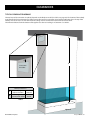
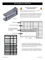
ENCLOSING the FIREPLACE
DO NOT ALLOW THE FIREPLACE
TO BEAR ANY WEIGHT
Dimension B
Dimension A and Dimension B, shown in Figure 28, must be equal
throughout the installation, no matter the model.
The wall framing must be at least 2”/50 mm (NON-combustible framing
ONLY) from the fireplace and the entire weight of the non-combustible
wallboard (see page 6) is carried by the framing. Since most Element4
fireplaces have two or three sides of glass, the upper wall framing is
usually hung from the ceiling or often cantilevered. See Figure 29.
Dimension A
Figure 28
Metal Framing
NON-combustible Wallboard
2”/50 mm Clearance Between
NON-combustible Framing
and Fireplace
Fireplace (typical)
Convection Air Outlet Area by Model
Model
Square
Inches
Square
Centimeters
Bidore 95
Modore 95
Trisore 95
Bidore 100H
Modore 100H
Trisore 100H
50
322
Bidore 140
77
477
Figure 29
Bioptica
75
484
Lucius 140
119
768
Lucius 140 C 1/3
77
497
Lucius 140 C 2/3
77
497
Lucius 140 T
112
722
Modore 140
60
387
Optica
40
258
Trisore 140
70
Table 7.
452
Element4 Gas Fireplaces
A convection air outlet is always required and the area of the
convection air outlet varies by fireplace model. Table 7 shows the
minimum total area required for the various Element4 models. This
table assumes an enclosed chase with a top or ‘ceiling’ and with the
convection air outlet(s) on the wall(s) of the chase.
However, if the chase takes the form of a ‘half-wall’ and there is no
top on the half-wall then convection air will escape out of the ‘top’
of the half-wall. In this case, outlets on the walls are not required.
47
EuropeanHome.com
ENCLOSING the FIREPLACE
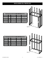
Rough Opening Dimensions for NON-COMBUSTIBLE Framing
A
B
C
Bioptica
Model Figure
30
463/4”/1184 mm
129/16”/319 mm
39”/986 mm
Lucius 140 T
30
65”/1652 mm
143/8”/364 mm
391/2”/1002 mm
Modore 95
30
451/2”/1152 mm
141/2”/368 mm
291/4”/742 mm
Modore 140
30
633/4”/1618 mm
141/2”/368 mm
291/4”/742 mm
Modore 100H
30
477/16”/1204 mm
1711/16”/448 mm
4011/16”/1032 mm
Optica
30
463/4”/1184 mm 131/2”/337 mm
Table 8
39”/986 mm
C
B
A
Figure 30
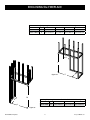
Rough Opening Dimensions for NON-COMBUSTIBLE Framing
Model Figure
D
E
F
291/4”/742 mm
Bidore 95
31
411/2”/1051 mm
141/2”/368 mm
Bidore 100H
31
431/2”/1105 mm
1711/16”/448 mm 4011/16”/1032 mm
Bidore 140
31
60”/1521 mm
141/2”/368 mm
291/4”/742 mm
Trisore 95
31
43”/1094 mm
14”1/2/368 mm
291/4”/742 mm
Trisore 100H
31
455/16”/1150 mm
173/4”/450 mm
4011/16”/1032 mm
Trisore 140
31
611/2”/1564 mm 141/2”/368 mm
Table 9
291/4”/742 mm
F
E
D
Figure 31
Element4 Gas Fireplaces
48
EuropeanHome.com
ENCLOSING the FIREPLACE
Rough Opening Dimensions for NON-COMBUSTIBLE Framing
I
J
Lucius 140 1/3
Model Figure
32
621/4”/1582 mm 201/2”/519 mm
G
H
185/16”/464 mm
391/2”/1002 mm
Lucius 140 2/3
32
621/4”/1582 mm 371/2”/949 mm
Table 10
185/16”/464 mm
391/2”/1002 mm
H
J
I
G
Figure 32
M
K
Rough Opening Dimensions for NON-COMBUSTIBLE Framing
Model Figure
Lucius 140 R
L
Figure 33
Element4 Gas Fireplaces
49
33
K
L
M
185/16”/464 mm 621/4”/1582 mm 391/2”/1002 mm
Table 11
EuropeanHome.com
ENCLOSING the FIREPLACE
COLD CLIMATE INSULATION
For cold climate installations, it is especially important to insulate outside the chase cavity, between studs and under the floor on
which appliance rests, if floor is above ground level. Gas line holes and other openings should be filled with approved firestop.
If the fireplace is being installed on a cement slab in cold climates, a sheet of plywood or a raised platform can be placed
underneath to prevent cold transferring to the fireplace and into the room. It also helps to tape for maximum air tightness and to
caulk firestops.
LOCATING THE CONTROLS
The control system for the Element4 fireplaces consist of three major components; the receiver, the transmitter and the gas
control. The transmitter is the remote control by which you operate the fireplace. The receiver and the gas control are at one end
of a 50”/1270 mm line set. The other end of the line set is connected to the approximate center of the firebox. As shipped, the line
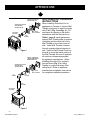
set is wrapped together and fixed beneath the fireplace. See Figure 24.
When locating the BDLE4 Access Door you must consider three types of access:
1. Line set access. The line set is to be unwrapped which allows the controls to be placed within a radius of
approximately 50”/1270 mm from the center of the fireplace, as the cable runs. Do not place the controls above the
level of the burner.
2. Physical access. Is the gas valve/receiver accessible for maintenance, etc.?
3. Wireless access. Can the signals from the transmitter (handheld, remote control) get to the receiver, inside the
access door?
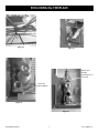
MOUNTING THE CONTROLS
The BDLE4 Access Door requires a rough opening of 913/16”/250 mm high by 615/16”/175 mm wide. The door should be mounted with
the hinge on the left side. The door can also be mounted with the hinge side down.
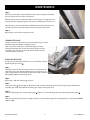
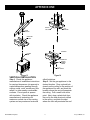
- Carefully cut the black tie wraps which hold the line set to the bottom of the fireplace then carefully unwrap the line set. Lay
the line set out towards the location of the BDLE4 while avoiding kinks and bends with a radius of less than 2”/50 mm. See Figure
34.
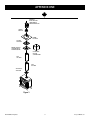
- Remove the four bolts holding the white door/frame cover to the frame, separate the frame and cover then mount the BDLE4
frame to the rough opening as shown in Figure 35.
- Replace the white door/frame cover onto the frame and secure it with the four bolts
- Fit the gas control tab into the bracket on the BDLE4 frame then tighten the bolt through the mounting bosses . See Figures 36
and 37
- Set the receiver into the BDLE4 bracket as shown in Figure 38 and connect the wall adapter.
When mounted, the BDLE4 should look like that shown in Figure 39.
Element4 Gas Fireplaces
50
EuropeanHome.com
ENCLOSING the FIREPLACE
One of the tie wraps which secure the line set.
Figure 34.
Figure 35.
Tighten bolt
through
mounting bosses
(at arrows)
Fit tab into
bracket on BDLE4
Figure 36.
Figure 37
Element4 Gas Fireplaces
51
EuropeanHome.com
ENCLOSING the FIREPLACE
Figure 38
Figure 39
Element4 Gas Fireplaces
52
EuropeanHome.com
FIRE MEDIA
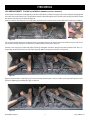
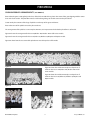
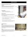
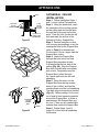
LOG ARRANGEMENTS (TRISORE 95, BIDORE 95, MODORE 95, OPTICA, BIOPTICA)
Ensure that the hearth panel is sitting firmly in the base of the fire box, with the long slot in the center of the panel aligning with
the center slots on the burner tube. The pilot flame must be visible through the panel and the cut-out in the pilot shield. Scatter
the embers over the panel, as shown in Figure 40.
Ensure no embers enter the pilot area, keeping the gap between the up-fold on the panel and the burner tube clear of embers.
Figure 43
Figure 40.
This is shown in detail, Figure 43. Position the large log centrally at the rear as shown in Figure 41, the three fir cones and one of
the small branch logs sit on the base of the fire, as shown. Make sure the pilot is still clear.
Position 2 more large logs at either end of the central log, noting that one will be sitting on top of the smaller branch. The 2 “Y”
shaped logs are then placed to lie on top of the large logs. Make sure the pilot is still clear. See Figure 41.
Figure 41
Figure 42 shows how the remaining logs are inserted. Finally check the pilot is clear, no embers have entered the pilot area and
the burner lighting is good before the glass is replaced.
Figure 42
Element4 Gas Fireplaces
53
EuropeanHome.com
FIRE MEDIA
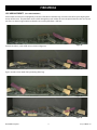
LOG ARRANGEMENTS (TRISORE 140, BIDORE 140, MODORE 140)
Ensure that the hearth panel is sitting firmly in the base of the fire box with the long slot in the center of the panel aligning with
the top of the burner. The pilot flame must be visible through the hearth panel. Place the coals as shown in Figure 44. Ensure that
the area near the pilot (circled) is left clear.
Figure 44
Pine
Cones
Figure 45
Position the coals and pine cones as shown in Figure 45. Figures 46 and 47 show detail of the positioning of the logs.
Finally, check that the pilot is clear, media has entered the pilot area and the burner lighting is good before the glass is replaced.
Figure 46
Figure 47
Element4 Gas Fireplaces
54
EuropeanHome.com
FIRE MEDIA
LOG ARRANGEMENTS (ALL LUCIUS MODELS)
Ensure that the hearth panel is sitting firmly in the base of the fire box with the long slot in the center of the panel aligning with
the top of the burner. The pilot flame must be visible through the panel and the cut-out in the pilot shield. Place the six coals and
two cones as shown in Figure 48. Ensure that the area near the pilot flame is left clear.
Figure 48
Position the embers, coals and fir cones as shown in Figure 49.
Figure 49
Figures 50 and 51 show detail of the positioning of the logs.
Figure 50
Figure 51
Element4 Gas Fireplaces
55
EuropeanHome.com
FIRE MEDIA
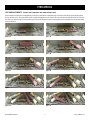
LOG ARRANGEMENTS (BIDORE 100H, MODORE 100H AND TRISORE 100H)
Ensure that the hearth panel is sitting firmly in the base of the fire box with the long slot in the center of the panel aligning with
the top of the burner. The pilot flame must be visible through the panel and the cut-out in the pilot shield. Place the six coals and
two cones as shown in Figure 52. Place the logs in the order shown in Figures 52 through 61. Ensure that the area inside the ember
shield is left clear.
Figure 52
Figure 53
Figure 54
Figure 55
Figure 56
Figure 57
Figure 58
Figure 59
Figure 60
Figure 61
Element4 Gas Fireplaces
56
EuropeanHome.com
FIRE MEDIA
CARRARA PEBBLES ARRANGEMENTS (ALL MODELS)
Ensure that the grate is sitting firmly in the base of the fire box with the long slot in the center of the grate aligning with the center
slots on the burner tube. The pilot flame must be visible through the grate and the cut-out in the pilot shield.
Scatter evenly the contents of the bags of pebbles over the top of the grate and burner.
Ensure that none of the pebbles enters the pilot enclosure.
The arrangement of the pebbles is now complete. However, it is important to check that the pilot flame is still visible.
Figure 62 shows the arrangement for Trisore 140, Bidore 140, Modore 140 and all Lucius models.
Figure 63 shows the arrangement for Trisore 95, Bidore 95, Modore 95, Bioptica and Optica models.
Figure 64 shows how the area around the pilot burner must be kept clear of fire media.
Figure 62
Figure 65 shows the 2nd thermocouple area kept clear of
media on the Trisore 140, Bidore 140, Modore 140 and all
Lucius models.
Figure 66 shows the 2nd thermocouple area kept clear of
media on the Trisore 95, Bidore 95, Modore 95, Bioptica and
Optica models.
Figure 63
Figure 64
Element4 Gas Fireplaces
Figure 65
Figure 66
57
EuropeanHome.com
OPERATING the FIREPLACE
BEFORE THE FIRST FIRE
1.
2.
3.
4.
5.
6.
Make sure all construction materials have been removed from inside and around the fireplace.
Confirm the proper placement of the burner media.
Confirm that the controls are properly connected.
Check the gas supply for leaks.
Close and properly clamp the glass panels.
Check that the venting is unobstructed and in proper working condition.
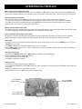
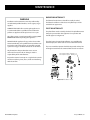
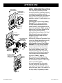
PAIRING THE REMOTE AND RECEIVER (Resetting the System)
The remote control must be paired to the receiver prior to first use. This is done as follows:
1. Press and hold the receiver reset button (Figure 67) until you hear the second of two beeps. After the second beep release the
reset button and,
2. within twenty seconds, press and hold the È button on the remote until you hear the second of two beeps. Release the È
button.
RESET BUTTON
Figure 67. Receiver
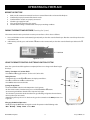
USING THE REMOTE CONTROL ELECTRONIC IGNITION SYSTEM
Note: The system shuts off the appliance completely if there is no change in the flame height
for 5 days.
Setting °C/24 Hour or °F/12 Hour Clock.
Press OFF andÈto toggle between °F/12 hr and °C/24 hr clock.
UP
Setting the time.
Simultaneously press theÈand Çbuttons, the display now flashes.
PressÇto set the hour andÈto set the minute.
Press OFF to return to manual mode.
DOWN
SET
OFF
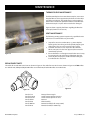
Igniting the Appliance.
Ensure the ON/OFF switch is in the ON position. See Figure 69.
On the remote control, simultaneously press and hold the OFF andÇbuttons.
An acoustic signal indicates that the start sequence has begun.
The electronic system then checks that the main gas is flowing and ignites the main burner;
this may take up to 20 seconds.
NOTE: During start-up, the MANUAL knob on the gas valve cannot be in the MAN position. See
Figure 69.
Changing the Mode of Operation.
Briefly pressing the SET button changes the mode of operation in the following order:
Man - Temp - Temp - Timer - back to Man
Element4 Gas Fireplaces
58
Figure 68. Remote Control
EuropeanHome.com
OPERATING the FIREPLACE
Man - Manual Flame Height Adjustment.
You are now able to use the remote control. To increase the flame, theÇbutton should be depressed. Pressing theÈbutton on
the handset will reduce the flame. The main flame may be lowered all the way down until it is off, leaving only the pilot ignited.
Fully Extinguishing the Appliance
From any heat setting, press the OFF button for a few seconds. This will cause the burner to fully extinguish.
The system has a safety interlock which will not allow the ignition until the interlock rests. This may take a few minutes.
The appliance should be shut off completely using the OFF button on the handset and not left on pilot only, except for
temporary use. This resets the system and all safety features.
Temp - Daytime Temperature mode.
The appliance must be in standby mode; pilot ignited. The room temperature is measured and compared to the set temperature.
The flame height is then automatically adjusted to reach the daytime set temperature.
Temp - Nighttime setback Temperature mode.
The appliance must be in standby mode; pilot ignited. The room temperature is measured and compared to the nighttime
setback temperature. The flame height is then automatically adjusted to achieve the nighttime setback temperature.
Timer mode.
The appliance must be in standby mode; pilot ignited. The Timer setting allows you to set 2 burner Temp times and 2 burner
Temp times every 24 hrs.
For Temp to operate as a thermostat, TEMP must be set at 4°C or higher.
If the Temp setting is decreased to - -, the motor will turn the valve to the standby position in the moon times and await the
next burner Temp cycle.
Setting the Temperature.
Select either the Temp MODE or the Temp MODE by briefly pressing the SET button.
Hold the SET button until the TEMP display flashes.
Set the desired temperature withÈorÇ.
Press OFF to complete the program.
Setting the Timer.
Select Timer mode by briefly pressing the SET button.
Press and hold the SET button until the P1 is displayed, and the time flashes. Set the hour by pressingÇand set the minutes by
pressingÈ.
Briefly press SET button for the next burner cycle time.
Once all 4 times are set, press OFF to complete the programming.
MANUAL KNOB IN
ON POSITION
MAIN VALVE KNOB
IN OFF POSITION
ON/OFF SWITCH IN
ON POSITION
Figure 69. Gas Valve
Element4 Gas Fireplaces
59
EuropeanHome.com
OPERATING the FIREPLACE
Automatic Turndown.
1. In Manual/Temperature/Timer modes, the valve will turn to pilot flame if there is no change in flame height for a six hour
period. In Temperature or Timer mode, if the ambient room temperature changes, the flame height will adjust automatically to
maintain set temperature and the fire will continue to function normally. The valve will turn to pilot flame if the set temperature
and the ambient room temperature remain the same over a six hour period.
2. The valve turns to pilot flame if the temperature in the receiver is higher than 140°F/60°C. The manin burner comes back on only
when the temperature is below 140°F/60°C.
Automatic Shut Off.
1. With low battery power in the receiver, the system shuts off the fire completely. This does not happen if the power supply is
interrupted.
2. The system shuts off the fire completely if there is no change in flame height for 5 days.
3. The system shuts off the fire if the main burner does not completely ignite approximately 20 seconds after ignition or after
pushing the Ç button.
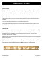
THE FIRST FIRE
The first time you light your fireplace an odor may be given off by the hot metal. This is normal and is a result of the ‘burn off’ of
the lubricants and sealants used when manufacturing the fireplace. We recommend that you open the nearby windows for extra
ventilation and operate the fireplace for at least four hours.
Upon lighting the fireplace when the glass is cold, some condensation may appear on the glass. This is normal and the
condensation will disappear as the glass warms.
During this first fire, examine the flame for appearance and quality. Examine the burner media for sooting. The flames should look
like those shown in Figure 70.
After this burn-off period, turn off the fireplace and let it cool completely to room temperature and clean both sides of the glass
and the interior panels as described in the MAINTENANCE section.
Since it is a metal fireplace, the heat-up and cool-down cycles may produce some noises caused by the expansion and contraction
of these metals. The premium materials and build quality of your fireplace will keep these sounds to a minimum.
Figure 70
Element4 Gas Fireplaces
60
EuropeanHome.com
MAINTENANCE
REMOVING AND CLEANING THE GLASS
OVERVIEW
The glass panels on this fireplace are held in place by a number of
retaining bolts and gasketed clamps. These instructions will show
you how to remove and install the clamps and glass panels.
Side Trim
Please read these instructions completely before proceeding.
1
TOOLS REQUIRED
•No. 2 Phillips screwdriver (not included)
•Vacuum clamp (included with ‘140’ model fireplaces only)
BEFORE YOU BEGIN
Except for tunnel and single-sided models, the first glass panel to be
removed is the one which is not touching a gasketed edge. This
panel is marked 1 in Figure 71.
Bottom Trim
•On Lucius models with three glass panels the small panel is 1 .
Figure 71
•On all Trisore and Bidore models the large panel is 1 . A Trisore 95
is shown as an example in Figure 71.
•On all other models the order does not matter.
Note: Some models have two sizes of glass clamps; a two-bolt clamp
and a one-bolt clamp. Figure 72 shows the two-bolt clamp.
REMOVING THE GLASS
Step 1.
Remove all of the trim pieces from the fireplace. The location and
quantity of trim varies with model but in every case there is no top
trim. The trim pieces are held firmly in place with magnets and will
simply lift out. The bottom (horizontal) trim pieces are at the lower
edge of the glass panels and the side (vertical pieces) are where the
glass meets the wall.
Two-bolt
Glass Clamp
Retaining Bolt
Step 2.
Gasketed glass clamps hold the edges of the glass panel in place.
The quantity and location of the clamps vary by model. Remove the
retaining bolt(s) holding the glass clamp and then remove the clamp.
Remove all of the retaining bolts and clamps holding in the first
piece of glass.
Element4 Gas Fireplaces
61
Figure 72
EuropeanHome.com
MAINTENANCE
Step 3.
Attach the vacuum glass clamp (if available) to the center of the glass and lift the
glass up into the clearance notch. See Figure 73.
When the glass panel is raised into the clearance notch there is enough clearance
to swing the lower edge of the glass panel over the standoff frame. See Figure 74.
When the glass panel is outside of the standoff frame then lower the glass panel
out of the clearance notch and carefully, and securely, set the panel aside.
Step 4.
Repeat Steps 2 and 3 for the other glass panels.
Figure 73
CLEANING THE GLASS
The glass should be cleaned as necessary with a fireplace glass cleaner.
We recommend Stove Bright® Gas Appliance Glass
Cleaner by Forrest Paint Co. It is available through your retailer.
Follow the instructions for use and do not clean the glass when it
is hot! If the glass becomes coated with deposits which cannot be
removed it must be replaced.
Glass Panel
INSTALLING THE GLASS
Standoff Frame
The glass panels should be installed in reverse order of their removal
beginning with glass panel 1 .
Step 1.
Lift the glass panel up into the clearance notch and swing the lower
edge of the glass panel against the firebox gasket. See Figure 73. Set
a glass clamp into place and hold it loosely into place with a retaining
bolt. DO NOT tighten the retaining bolt yet.
Firebox Gasket
Figure 74
Step 2.
Repeat Step 1 with the remaining glass panels.
Step 3.
Center glass panel 1 , left and right, on the fireplace and screw the retaining bolts into the lower glass clamp until the bolts
touch the glass clamp. Repeat for the remaining glass clamps on this glass panel.
Step 4.
Slide the adjoining glass panel against glass panel 1 . If there is a second adjoining glass panel slide it against glass panel 1 .
Step 5.
While ensuring that the glass panels are tight and square to each another, tighten the retaining bolt(s) on each clamp NO MORE
THAN 1/2 TURN.
Element4 Gas Fireplaces
62
EuropeanHome.com
MAINTENANCE
BURNER MAINTENANCE
WARNING
Installation and maintenance must be performed by
an authorized qualified installer, service agency or gas
supplier.
The flames from the burner should be visually checked.
The flame should have a blue base and yellow tops and be
candle-like in appearance.
TURN OFF THE GAS before servicing the appliance. It
is recommended that a qualified service technician
perform an appliance check-up/service once a year.
PILOT MAINTENANCE
The pilot flame must be visually checked. The pilot flame must
always be present when the appliance is in operation and
should appear as in Figure 76.
Any safety screen or guard removed for servicing MUST
BE REPLACED before operating this appliance.
The pilot burner has two distinct flames, one engulfing the
thermocouple, the other reaches across to the main burner.
DO NOT USE this appliance if any part has been under
water. Immediately, call a qualified service technician to
inspect the unit and to replace any part of the control
system and any gas control that has been under water.
The area around the injector should be inspected and any lint
or foreign material must be removed with a brush or vacuum.
Any alteration to the product that causes soot or
carbon to form and results in damage is not the
responsibility of the manufacturer.
Pilot Injector Natural - Marking 31.2
Pilot Injector Propane - Marking 27.1
Inspect the external vent cap on a regular basis to make
sure that no debris, plants, trees, shrubs are interfering
with the air flow.
3mm
Figure 75. Pilot Burner Detail
Element4 Gas Fireplaces
63
EuropeanHome.com
MAINTENANCE
THERMOCOUPLE MAINTENANCE
The Element4 fireplaces have two thermocouples; one next to
the pilot flame and one opposite the pilot burner on the other
side of the main burner. The completeness and operation of
both must be checked. A qualified installer must confirm that
the thermocouple is in place and not cracked or damaged.
Figure 76 shows a typical pilot flame engulfing the first thermocouple (shown on a Trisore 95.)
VENT MAINTENANCE
The following venting system inspection by a qualified service
technician is recommended every six months:
1. Inspect for excessive condensation, e.g. water droplets
forming in the inner lining and subsequently dripping out
of the joints. This can cause corrosion in the system.
2. Check for corrosion in areas exposed to the elements.
Where rust spots or holes have appeared, these must be
immediately replaced.
3. Ensure that there is no foreign material in the vents. Survey
by removing the cap and shining a light down the vent.
4. Check all joints and pipes to make sure that nothing has
been disturbed or loosened.
Figure 76
REPLACEMENT PARTS
Natural Gas Injector - marked 1200
The orifice for 95Propane
and 100H
series- burners
Gas Injector
marked 320shown in Figure 77. The orifice for 140 series burners shown in Figure 78. All NG orifices
are marked 1200, all Bioptica/Optica LP orifices are marked 260, all other LP orifices are marked 380.
Figure 78
Figure 77
E4-GS-1T-01
E4-GS-2T140-01
E4-GS-2T95-02
E4-GS-CM-01
E4-GS-PA-01
E4-GS-XMIT-01
E4-GS-RC-01
Element4 Gas Fireplaces
Primary Thermocouple
2nd Thermocouple for 140 series
2nd Thermocouple for 95 series
Receiver
Pilot Assembly
Remote Control (for all except 100H)
Remote Control (for 100H only)
64
EuropeanHome.com
WARRANTY
PRODUCT INSTALLATION RECORD
Installer: Please complete this form. Customer: Please retain this information.
Purchased From
Date of Purchase
Installed By
Date of Installation
Fireplace Serial Number
Fuel Type
Element4 Gas Fireplaces
65
EuropeanHome.com
APPENDIX ONE
9HQWLQJ6\VWHP)RU'LUHFW9HQW
*DV6WRYHVDQG)LUHSODFHV
Element4 Gas Fireplaces
66
DirectVent Pro
VENTING
SYSTEMInstructions
INSTALLATION INSTRUCTIONS
Installation
EuropeanHome.com
APPENDIX ONE
$0$-25&$86(2)9(175(/$7('),5(6,6)$,/85(
720$,17$,15(48,5('&/($5$1&(6$,563$&(672
&20%867,%/(0$7(5,$/6,7,62)7+(870267,03257$1&(
7+$7'28%/(:$//',5(&79(17352%(,167$//('21/<,1
$&&25'$1&(:,7+7+(6(,16758&7,216
,03257$17
5HDGWKURXJKDOORIWKHVHLQVWUXFWLRQV
EHIRUHEHJLQQLQJ\RXULQVWDOODWLRQ)DLOXUH
WRLQVWDOOWKLVSURGXFWDVGHVFULEHGLQWKHVH
LQVWUXFWLRQVZLOOYRLGWKHPDQXIDFWXUHU·V
ZDUUDQW\PD\FUHDWHDÀUHRURWKHUVDIHW\
KD]DUGDQGPD\DIIHFW\RXUKRPHRZQHU·V
LQVXUDQFHDQGVDIHW\OLVWLQJRI\RXU
DSSOLDQFH
.HHSWKHVHLQVWUXFWLRQVIRUIXWXUH
UHIHUHQFH
Element4 Gas Fireplaces
'HDU&XVWRPHU,QVWDOOHURU(QG8VHU
:HZHOFRPHDQ\FRPPHQWVUHJDUGLQJPDWWHUV
SHUWDLQLQJWRRXU'XUD9HQWSURGXFWV
:HZHOFRPHDQ\LGHDVLQSXWRUFRPSODLQWV
DQG,¶OOPDNHVXUHWKDWVRPHRQHUHVSRQGV
GLUHFWO\EDFNWR\RX
6HQG\RXUHPDLOVWR
SUHVLGHQW#GXUDYHQWFRP
,I\RXDUHVHDUFKLQJIRUWHFKVXSSRUWRUSURGXFW
LQIRUPDWLRQSOHDVHSKRQHXVDW
2UHPDLOXVDW
WHFKVXSSRUW#GXUDYHQWFRP
67
EuropeanHome.com
APPENDIX ONE
)RUWKHPRVWXSWRGDWHLQVWDOODWLRQLQVWUXFWLRQVVHHZZZGXUDYHQWFRP
&217(176
DirectVent Pro
VENTING SYSTEM FOR DIRECT VENT GAS STOVES AND FIREPLACES
Application | Warning | Safety & Installation Precautions
65
$SSOLFDWLRQ_:DUQLQJ_6DIHW\,QVWDOODWLRQ3UHFDXWLRQV
Options | Planning Your Installation
66
2SWLRQV_3ODQQLQJ<RXU,QVWDOODWLRQ
Horizontal Installation
67
+RUL]RQWDO,QVWDOODWLRQ
Snorkels
71
6QRUNHOV
,QVWDOOLQJ9LQ\O6LGLQJ6WDQGRII
Installing Vinyl Siding Standoff
73
,QVWDOOLQJ&RXQWHU)ODVKLQJ
Installing Counter Flashing
74
9HUWLFDO,QVWDOODWLRQ
Vertical Installation
75
&DWKHGUDO&HLOLQJ,QVWDOODWLRQ
Cathedral Ceiling Installation
79
*HQHUDO0DLQWHQDQFH/DEHOV
General Maintenance / Labels
81
6XSSOHPHQWDO&DQDGLDQ,QVWUXFWLRQV
Supplemental Canadian Instructions
82
:DUUDQW\
M&G DuraVent Warranty
84
Element4 Gas Fireplaces
68
EuropeanHome.com
APPENDIX ONE
$33/,&$7,21
QHDUE\FRPEXVWLEOHVXUIDFHV%H
VXUHWRFKHFNWKHYHQWWHUPLQDWLRQ
FOHDUDQFHUHTXLUHPHQWVIURPGHFNV
ZLQGRZVVRI¿WVJDVUHJXODWRUVDLU
VXSSO\LQOHWVDQGSXEOLFZDONZD\V
DVVSHFL¿HGLQWKHVHLQVWDOODWLRQ
LQVWUXFWLRQVDQGORFDOEXLOGLQJFRGHV
7KHJDVDSSOLDQFHDQGYHQWV\VWHP
PXVWEHYHQWHGGLUHFWO\WRWKHRXWVLGH
RIWKHEXLOGLQJDQGQHYHUEHDWWDFKHG
WRDFKLPQH\VHUYLQJDVHSDUDWHVROLG
IXHORUJDVEXUQLQJDSSOLDQFH(DFK
GLUHFWYHQWJDVDSSOLDQFHPXVWXVHLWV
RZQVHSDUDWHYHQWV\VWHP&RPPRQ
YHQWV\VWHPVDUHSURKLELWHG
,03257$17
6$)(7<35(&$87,216
)257+(,167$//(5
7KHVHLQVWUXFWLRQVDSSO\WRWKH0*
'XUD9HQW'LUHFW9HQW3UR´[´
DQG´[´V\VWHPV7KLVYHQWLQJ
V\VWHPLQFRPELQDWLRQZLWKWKHJDV
DSSOLDQFHKDVEHHQWHVWHGDQGOLVWHG
DVDGHFRUDWLYHJDVDSSOLDQFHV\VWHP
RUDVDGLUHFWYHQWKHDWHUV\VWHP
E\DPDMRUWHVWLQJDJHQF\VXFKDV
8/$*$&*$201,RU:DUQRFN
+HUVH\&KHFNWKHPDQXIDFWXUHU¶V
UDWLQJSODWHDQGLQVWUXFWLRQPDQXDOWR
FRQ¿UPWKDWWKH0*'XUD9HQW'LUHFW
9HQWLVDSSURYHGIRUXVHRQWKHEUDQG
QDPHDSSOLDQFH\RXKDYHVHOHFWHG
5HDGDOOLQVWUXFWLRQVFDUHIXOO\EHIRUH
VWDUWLQJWKHLQVWDOODWLRQ)DLOXUHWRIROORZ
WKHVHLQVWUXFWLRQVPD\FUHDWHD¿UHRU
RWKHUVDIHW\KD]DUGDQGZLOOYRLGWKH
ZDUUDQW\&KHFNZLWKWKHDSSOLDQFH
PDQXIDFWXUHU¶VLQVWDOODWLRQ
LQVWUXFWLRQVIRUVSHFL¿FYHQWLQJ
DQGFOHDUDQFHWRFRPEXVWLEOH
UHTXLUHPHQWVZKLFKPD\YDU\IURP
RQHDSSOLDQFHWRDQRWKHU%HVXUH
WRFRPSO\ZLWKPLQLPXPRUPD[LPXP
GLVWDQFHVRIYHUWLFDORUKRUL]RQWDO
UXQVDVSUHVFULEHGLQWKHDSSOLDQFH
PDQXIDFWXUHU¶VLQVWDOODWLRQLQVWUXFWLRQV
:$51,1*
$OZD\VPDLQWDLQUHTXLUHGFOHDUDQFHV
DLUVSDFHVWRQHDUE\FRPEXVWLEOHV
WRSUHYHQWD¿UHKD]DUG'RQRW¿OO
DLUVSDFHVZLWKLQVXODWLRQ%HVXUHWR
FKHFNWKHDSSOLDQFHPDQXIDFWXUHU¶V
LQVWDOODWLRQLQVWUXFWLRQVIRUPLQLPXP
FOHDUDQFHUHTXLUHPHQWVEHWZHHQ
WKHRXWHUZDOOVRIWKHYHQWSLSHDQG
:HDUJORYHVDQGVDIHW\JODVVHVIRU
SURWHFWLRQ
([HUFLVHH[WUHPHFDXWLRQZKHQ
XVLQJODGGHUVRURQURRIWRSV
%HDZDUHRIHOHFWULFDOZLULQJ
ORFDWLRQVLQZDOOVDQGFHLOLQJV
,167$//$7,21
35(&$87,216
7KH0*'XUD9HQW'LUHFW9HQW3UR
LVDQHQJLQHHUHGSURGXFWWKDWKDV
EHHQGHVLJQHGDQGWHVWHGIRUXVHZLWK
DSSURYHGGLUHFWYHQWJDVDSSOLDQFHV
RQO\7KH0*'XUD9HQWZDUUDQW\ZLOO
EHYRLGHGDQGVHULRXV¿UHKHDOWKRU
RWKHUVDIHW\KD]DUGVPD\UHVXOWIURP
DQ\RIWKHIROORZLQJDFWLRQV
,QVWDOODWLRQRIDQ\GDPDJHG
'LUHFW9HQW3URFRPSRQHQW
8QDXWKRUL]HGPRGL¿FDWLRQRIWKH
'LUHFW9HQW3UR6\VWHP
,QVWDOODWLRQRIDQ\QRQ'LUHFW9HQW3UR
SLSHRUFRPSRQHQWSDUWQRWDSSURYHG
Element4 Gas Fireplaces
69
EuropeanHome.com
APPENDIX ONE
E\0*'XUD9HQWRUWKHDSSOLDQFH
PDQXIDFWXUHU
,QVWDOODWLRQRWKHUWKDQDVLQVWUXFWHG
E\0*'XUD9HQWRUWKHDSSOLDQFH
PDQXIDFWXUHU
ROUND
HORIZONTAL
TERMINATION
CAP SHOWN
PIPE
SECTION
&RQVXOW\RXUORFDOEXLOGLQJFRGHV
EHIRUHEHJLQQLQJWKHLQVWDOODWLRQ
237,216
7KH0*'XUD9HQW'LUHFW9HQW3UR
RIIHUVDFRPSOHWHOLQHRIFRPSRQHQW
SDUWVIRUERWKKRUL]RQWDODQGYHUWLFDO
LQVWDOODWLRQV0DQ\LWHPVDUHRIIHUHGLQ
GHFRUDWLYHEODFNDVZHOODVJDOYDQL]HG
¿QLVK7KHJDOYDQL]HGSLSHDQG
¿WWLQJVPD\EHXVHGIRUFRQFHDOHG
ORFDWLRQVVXFKDVDWWLFVRUVSDFHV
ZKHUHFRUURVLRQLVDIDFWRUVXFKDV
DERYHWKHURRÀLQH'HFRUDWLYHEODFN
SDLQWHGVHFWLRQVDUHUHFRPPHQGHG
IRUXVHRQYLVLEOHLQWHULRUUXQV
6QRUNHO7HUPLQDWLRQVDUHDYDLODEOHIRU
DSSOLFDWLRQVZKLFKPD\UHTXLUHYHUWLFDO
ULVHRQWKHEXLOGLQJH[WHULRU
ELBOW
)LJXUH
SQUARE
HORIZONTAL
TERMINATION
CAP SHOWN
ROUND CEILING
SUPPORT/WALL
THIMBLE COVER
90°
ELBOW
3/$11,1*<285
,167$//$7,21
7KHUHDUHWZREDVLFW\SHVRI
'LUHFW9HQW3URLQVWDOODWLRQV&KHFNWKH
DSSOLDQFHPDQXIDFWXUHU¶VLQVWDOODWLRQ
LQVWUXFWLRQVWRFRQ¿UPZKDWW\SHV
RILQVWDOODWLRQVDUHSHUPLWWHGDQG
FKHFNIRUDQ\YHQWLQJUHVWULFWLRQV
VXFKDVPD[LPXPKRUL]RQWDOUXQDQG
PLQLPXPRUPD[LPXPYHUWLFDOULVH
7KHWZRW\SHVRILQVWDOODWLRQVDUH
+RUL]RQWDO7HUPLQDWLRQ)LJVDQG
9HUWLFDO7HUPLQDWLRQ)LJ
:KHQSODQQLQJ\RXULQVWDOODWLRQ
LWZLOOEHQHFHVVDU\WRVHOHFWWKH
WALL
THIMBLE
APPLIANCE
ADAPTOR
PIPE
SECTION
PIPE
SECTION
APPLIANCE
ADAPTOR
)LJXUH
Element4 Gas Fireplaces
70
EuropeanHome.com
APPENDIX ONE
VERTICAL
HIGH WIND
TERMINATION
CAP SHOWN
STORM
COLLAR
ROOF
FLASHING
CEILING
FIRESTOP
ROUND CEILING
SUPPORT/WALL
THIMBLE COVER
CATHEDRAL
CEILING
SUPPORT BOX
PIPE
SECTION
LPSRUWDQWWRQRWHWKHZDOOWKLFNQHVV
6HOHFWWKHDPRXQWRIYHUWLFDOULVH
GHVLUHGRUUHTXLUHGIRU³YHUWLFDOWR
KRUL]RQWDO´LQVWDOODWLRQVYHULI\WKDWLW
LVZLWKLQWKHDSSOLDQFHPDQXIDFWXUHU¶V
PLQLPXPDQGPD[LPXPOLPLWV7R
GHWHUPLQHWKHOHQJWKRIYHQWSLSH
UHTXLUHGIRUYHUWLFDOLQVWDOODWLRQV
PHDVXUHWKHGLVWDQFHIURPWKH
DSSOLDQFHÀXHRXWOHWWRWKHFHLOLQJ
WKHFHLOLQJWKLFNQHVVWKHYHUWLFDOULVH
LQDQDWWLFRUVHFRQGVWRU\DQGDOORZ
IRUVXI¿FLHQWYHQWKHLJKWDERYHWKH
URRÀLQH)RUWZRVWRU\DSSOLFDWLRQV
)LUHVWRSVDUHUHTXLUHGDWHDFKÀRRU
FHLOLQJOHYHO,IDQRIIVHWLVQHHGHGLQ
WKHDWWLFDGGLWLRQDOSLSHDQGHOERZV
ZLOOEHUHTXLUHG
+25,=217$/,167$//$7,21
PIPE
SECTION
APPLIANCE
ADAPTOR
)LJXUH
SURSHUOHQJWKRIYHQWSLSHIRU
\RXUSDUWLFXODUUHTXLUHPHQWV)RU
KRUL]RQWDOLQVWDOODWLRQVFKHFNWKH
DSSOLDQFHPDQXIDFWXUHU¶VLQVWDOODWLRQV
LQVWUXFWLRQVWRGHWHUPLQHWKH
PLQLPXPFOHDUDQFHIURPWKHUHDURI
WKHDSSOLDQFHWRWKHZDOO,WLVDOVR
6WHS6HWWKHJDVDSSOLDQFHLQLWV
GHVLUHGORFDWLRQ&KHFNWRGHWHUPLQH
LIZDOOVWXGVRUURRIUDIWHUVDUHLQ
WKHZD\RQFHWKHYHQWLQJV\VWHP
LVDWWDFKHG,IWKLVLVWKHFDVH\RX
PD\ZDQWWRDGMXVWWKHORFDWLRQRIWKH
DSSOLDQFH
6WHS'LUHFW9HQW3URSLSHDQG
¿WWLQJVDUHGHVLJQHGZLWKVSHFLDOWZLVW
ORFNFRQQHFWLRQV7RFRQQHFWWKH
YHQWLQJV\VWHPWRWKHDSSOLDQFHÀXH
RXWOHWDWZLVWORFN$SSOLDQFH$GDSWRU
LVUHTXLUHG:LWKVRPHEUDQGVRI
DSSOLDQFHVWKH0*'XUD9HQW
$SSOLDQFH$GDSWRUZLOOEHEXLOWLQWRWKH
DSSOLDQFHDWWKHIDFWRU\:LWKRWKHU
EUDQGVWKHDGDSWRUZLOOEHVXSSOLHG
E\WKHDSSOLDQFHPDQXIDFWXUHUIRU
LQVWDOODWLRQLQWKH¿HOG$VVHPEOHWKH
GHVLUHGFRPELQDWLRQRI3LSH6HFWLRQV
DQG(OERZVWRWKH$SSOLDQFH$GDSWRU
)LJ
Element4 Gas Fireplaces
71
EuropeanHome.com
APPENDIX ONE
1RWHV
7ZLVWORFNSURFHGXUH/LQHXS
ORFNLQJOXJVRQPDOHDQGIHPDOHHQGV
RISLSHVHFWLRQV,QVHUWWKHPDOHHQG
RISLSHLQWRWKHIHPDOHHQGXQWLOWKH
ORFNLQJOXJVDUHFRYHUHG7ZLVWWKH
IHPDOHHQGFORFNZLVHDQHLJKWKRID
WXUQWRORFNVHFWLRQVWRJHWKHU)LJ
6FUHZVDUHQRWUHTXLUHGWRVHFXUHWKH
MRLQWEXWDUHDFFHSWDEOHSURYLGHGWKH\
GRQRWSHQHWUDWHWKHLQQHUZDOORIWKH
YHQWSLSH
+RUL]RQWDOUXQVRIYHQWSLSH
PXVWEHVXSSRUWHGWRSUHYHQWDQ\
GRZQZDUGVDJV+RUL]RQWDOSLSH
VHFWLRQVVKRXOGEHVXSSRUWHGDWOHDVW
HYHU\IHHW:DOO6WUDSVFDQEH
XVHGIRUWKLVSXUSRVH$OWHUQDWLYHO\
SOXPEHUVWDSHRURWKHUVXLWDEOH
QRQFRPEXVWLEOHPDWHULDOFDQEHXVHG
WRVXSSRUWWKHYHQWSLSH
'LUHFW9HQW3URYHQWLQJUHTXLUHVQR
VHDODQWXQOHVVVSHFL¿FDOO\UHTXLUHGE\
DSSOLDQFHPDQXIDFWXUHU
6WHS:LWKWKH$SSOLDQFH$GDSWRU
DQG3LSH6HFWLRQDWWDFKHGWRWKH
DSSOLDQFHVOLGHWKHDSSOLDQFHLQWRLWV
FRUUHFWORFDWLRQDQGPDUNWKHZDOO
IRUDVTXDUHKROHRIWKHDSSURSULDWH
VL]H5HIHUWR7DEOHSDJHIRU
WKHFRUUHFWVL]HVTXDUHRSHQLQJ
XQOHVVRWKHUZLVHVSHFL¿HGE\WKH
DSSOLDQFHPDQXIDFWXUHU¶VFOHDUDQFH
UHTXLUHPHQWV7KHFHQWHUOLQHRIWKH
SLSHVKRXOGOLQHXSZLWKWKHFHQWHU
RIWKHVTXDUHKROH)LJ&XW
DQGIUDPHWKHVTXDUHKROHLQWKH
H[WHULRUZDOOZKHUHWKHYHQWZLOO
EHWHUPLQDWHG$:DOO7KLPEOHRU
:DOO)LUHVWRSPD\EHUHTXLUHGE\WKH
DSSOLDQFHPDQXIDFWXUHUDVDGGLWLRQDO
WKHUPDOSURWHFWLRQIRUWKHZDOO,IWKH
)LJXUH
MALE
END
OPTIONAL
SCREWS
FEMALE
END
)LJXUH
CENTER
OF HOLE
CL
)LJXUH
Element4 Gas Fireplaces
72
EuropeanHome.com
APPENDIX ONE
7$%/(
',5(&79(17352)5$0,1*25&87287',0(16,216
672&.180%(5
'9$:7
'9$:76
'9$:78
'9$&6
'9$)6
'9$:)6
'9$966
'9$&)
'9$&).
'9$&).6
'9$96.
'9$96.6
'9$,6
'9$:7
'9$:76
'9$:78
'9$&6
'9$)6
'9$:)6
'9$966
'9$96.
'9$&)
'9$&).
'9$,6
&20321(17'(6&5,37,21
:DOO7KLPEOH
:DOO7KLPEOH6PDOO
:DOO7KLPEOH8QLYHUVDO
&HLOLQJ6XSSRUW
)LUH6WRS
:DOO)LUH6WRS
9LQ\O6LGLQJ6WDQGRII
&RXQWHU)ODVKLQJ$VVHPEOHG
&RXQWHU)ODVKLQJSF.LW
&RXQWHU)ODVKLQJ.LW6PDOO
9LQ\O6LGLQJ6WDQGRII3F.LW
9LQ\O6LGLQJ6WDQGRII.LW6PDOO
,QVXODWLRQ6KLHOG
:DOO7KLPEOH
:DOO7KLPEOH6PDOO
:DOO7KLPEOH8QLYHUVDO
&HLOLQJ6XSSRUW
)LUH6WRS
:DOO)LUH6WRS
9LQ\O6LGLQJ6WDQGRII
9LQ\O6LGLQJ6WDQGRII3F.LW
&RXQWHU)ODVKLQJ$VVHPEOHG
&RXQWHU)ODVKLQJSF.LW
,QVXODWLRQ6KLHOG
ZDOOEHLQJSHQHWUDWHGLVFRQVWUXFWHG
RIQRQFRPEXVWLEOHPDWHULDORQO\LH
PDVRQU\EORFNEULFNRUFRQFUHWHRQO\
DKROHZLWK]HURFOHDUDQFHWRWKHYHQW
SLSHLVSHUPLVVLEOHLIDOORZHGE\WKH
DSSOLDQFHPDQXIDFWXUHU
1RWHV
7KHKRUL]RQWDOUXQRIYHQWLQJ
PXVWEHOHYHORUKDYHDLQFKULVH
IRUHYHU\IRRWRIUXQWRZDUGVWKH
WHUPLQDWLRQ1HYHUDOORZWKHYHQWWRUXQ
GRZQZDUG$GRZQZDUGVORSHFDQWUDS
KHDWDQGEHFRPHDSRVVLEOH¿UHKD]DUG
7KHORFDWLRQRIWKH+RUL]RQWDO9HQW
7HUPLQDWLRQRQDQH[WHULRUZDOOPXVW
PHHWDOOORFDODQGQDWLRQDOEXLOGLQJ
6,=(
´[´
´[´
´[´
´[´
´[´
´[´
´[´
´[´
´[´
´[´
´[´
´[´
´[´
´[´
´[´
´[´
´[´
´[´
´[´
´[´
´[´
´[´
´[´
´[´
FRGHVDQGPXVWQRWEHHDVLO\EORFNHG
RUREVWUXFWHG7HUPLQDWLRQFOHDUDQFHV
DUHDVIROORZV
D&OHDUDQFHDERYHWKHJURXQG
YHUDQGDSRUFKGHFNRUEDOFRQ\
LQFKHVPLQLPXP
E&OHDUDQFHWRDZLQGRZRSHUDEOH
RU¿[HGFORVHGRUGRRULQFKHV
PLQLPXP
F9HUWLFDOFOHDUDQFHWRDYHQWLODWHG
VRI¿WORFDWHGDERYHWKH7HUPLQDWLRQ&DS
LIVRI¿WH[WHQGVDKRUL]RQWDOGLVWDQFH
RIIHHWRXWRYHUWKHFHQWHUOLQHRIWKH
WHUPLQDWLRQLQFKHVPLQLPXP
G&OHDUDQFHWRDQXQYHQWLODWHGVRI¿W
LQFKHVPLQLPXP
Element4 Gas Fireplaces
73
EuropeanHome.com
APPENDIX ONE
H&OHDUDQFHWRDQRXWVLGHFRUQHUDV
WHVWHGE\DSSOLDQFHPDQXIDFWXUHU
I&OHDUDQFHWRDQLQVLGHFRUQHUDV
WHVWHGE\DSSOLDQFHPDQXIDFWXUHU
J1RWWREHLQVWDOOHGDERYHDPHWHU
UHJXODWRUDVVHPEO\ZLWKLQIHHW
KRUL]RQWDOO\IURPWKHFHQWHUOLQHRIWKH
UHJXODWRU
K&OHDUDQFHWRDVHUYLFHUHJXODWRU
YHQWRXWOHWIHHWPLQLPXP
L&OHDUDQFHWRQRQPHFKDQLFDO
DLUVXSSO\LQOHWWRDEXLOGLQJRUWKH
FRPEXVWLRQDLULQOHWWRDQ\RWKHU
DSSOLDQFHLQFKHVPLQLPXP
M&OHDUDQFHWRDPHFKDQLFDODLUVXSSO\
LQOHWIHHWPLQLPXP
N&OHDUDQFHDERYHDSDYHGVLGHZDON
RUSDYHGGULYHZD\ORFDWHGRQSXEOLF
SURSHUW\UHIHUWRORFDOFRGH
O&OHDUDQFHXQGHUDYHUDQGDSRUFK
GHFNRUEDOFRQ\LQFKHVPLQLPXP
6WHS3RVLWLRQWKH+RUL]RQWDO
7HUPLQDWLRQ&DSLQWKHFHQWHURIWKH
VTXDUHIUDPHGKROHDQGDWWDFKWRWKH
H[WHULRUZDOOZLWKWKHIRXUZRRGVFUHZV
SURYLGHG%HIRUHDWWDFKLQJWKHYHQW
WHUPLQDWLRQFDSWRWKHH[WHULRUZDOO
UXQDEHDGRIQRQKDUGHQLQJVLOLFRQH
VHDODQWDURXQGLW¶VRXWVLGHHGJHVWR
PDNHDVHDOEHWZHHQWKHFDSDQGWKH
ZDOO7KHDUURZRQWKHYHQWFDSVKRXOG
EHSRLQWLQJXS(QVXUHWKDWSURSHU
FOHDUDQFHVWRFRPEXVWLEOHPDWHULDOVDUH
PDLQWDLQHG)LJ
1RWHV
7KHIRXUZRRGVFUHZVSURYLGHG
VKRXOGEHUHSODFHGZLWKDSSURSULDWH
WOOD
SCREWS
HOT
)LJXUH
IDVWHQHUVIRUXVHRQEULFNFRQFUHWH
EORFNRURWKHUW\SHVRIVLGLQJV
)RUEXLOGLQJVZLWKYLQ\OVLGLQJRU
RWKHUVXUIDFHVWKH9LQ\O6LGLQJ6WDQGRII
RU&RXQWHU)ODVKLQJLVDYDLODEOH
6WHS%HIRUHFRQQHFWLQJ\RXU
KRUL]RQWDO3LSH6HFWLRQVWRWKH
+RUL]RQWDO7HUPLQDWLRQ&DSVOLGHWKH
:DOO7KLPEOH&RYHURYHUWKH3LSH
6HFWLRQQHDUHVWWKHLQWHULRUVLGHRIZDOO
)LJ
6WHS6OLGHWKHDSSOLDQFHDQGYHQW
DVVHPEO\WRZDUGVWKHZDOOFDUHIXOO\
Element4 Gas Fireplaces
74
EuropeanHome.com
APPENDIX ONE
6125.(/6
SHEET
METAL
SCREWS
WALL
THIMBLE
COVER
)LJXUH
WOOD
SCREWS
)LJXUH
LQVHUWLQJWKH3LSH6HFWLRQLQWRWKHFDS
DVVHPEO\,WLVLPSRUWDQWWKDWWKH3LSH
6HFWLRQH[WHQGVLQWRWKHEDFNRIWKH
7HUPLQDWLRQ&DSZLWKDPLQLPXPRYHUODS
RILQFKHV8VHWKHWZRVKHHWPHWDO
VFUHZVSURYLGHGWRVHFXUHWKH3LSH
6HFWLRQWRWKHEDFNRIWKH7HUPLQDWLRQ
&DS7KH:DOO7KLPEOH&RYHUZLOOFRYHU
WKHVFUHZKHDGV)LJ
6WHS6OLGHWKH:DOO7KLPEOH&RYHU
XSWRWKHZDOOVXUIDFHDQGDWWDFKWR
WKHZDOOZLWKVFUHZVSURYLGHG)LJ
$SSO\RSWLRQDOGHFRUDWLYHEUDVVWULPWR
:DOO7KLPEOH&RYHULIGHVLUHG
)RULQVWDOODWLRQVUHTXLULQJDYHUWLFDO
ULVHRQWKHH[WHULRURIWKHEXLOGLQJ
LQFKDQGLQFKWDOO6QRUNHO
7HUPLQDWLRQVDUHDYDLODEOH)LJ
)ROORZWKHVDPHJHQHUDOLQVWDOODWLRQ
SURFHGXUHVDVXVHGIRUDVWDQGDUG
+RUL]RQWDO7HUPLQDWLRQ7KHVWDQGDUG
:DOO7KLPEOHRU:DOO)LUHVWRSFDQ
EHXVHGZLWKWKH6QRUNHOEXWWKH
H[WHULRUSODWHZLOORYHUKDQJWKHHGJHV
RIWKH6QRUNHO+RZHYHUDXQLYHUVDO
:DOO7KLPEOHLVDYDLODEOHIRUXVH
ZLWKWKH6QRUNHOWKDWLVQRWYLVLEOH
RQWKHH[WHULRURIWKHEXLOGLQJRU
'9$:787RLQVWDOOWKH8QLYHUVDO
:DOO7KLPEOHLQVHUWWKHWKLPEOHIURP
WKHLQWHULRURIWKHKRXVHDQGDGMXVW
WKHOHQJWKRIWKHWXEHWRHQVXUHLW
WRXFKHVWKHEDFNVLGHRIWKH6QRUNHO
ZKHQLQVWDOOHG)LJ6HFXUHWKH
WXEHLQSODFHXVLQJVKHHWPHWDO
VFUHZV0RXQWWKH:DOO7KLPEOH
LQSODFH$WWDFKWKH6QRUNHOWRWKH
ZDOOXVLQJZRRGVFUHZVRURWKHU
DSSURSULDWHIDVWHQHUVGHSHQGLQJ
RQZDOOFRQVWUXFWLRQ,IWKH6QRUNHO
7HUPLQDWLRQPXVWEHLQVWDOOHGEHORZ
JUDGHOHYHOHJLQDEDVHPHQW
DSSOLFDWLRQSURSHUGUDLQDJHPXVW
EHSURYLGHGWRSUHYHQWZDWHUIURP
HQWHULQJWKH6QRUNHO7HUPLQDWLRQ
)LJ'RQRWDWWHPSWWRHQFORVH
WKH6QRUNHOZLWKLQWKHZDOORUDQ\
RWKHUW\SHRIHQFORVXUH
Element4 Gas Fireplaces
75
EuropeanHome.com
APPENDIX ONE
SNORKEL
OPTIONAL DVA-WTU
ADJUST AND SECURE
TELESCOPING THIMBLE
SLEEVES WITH SCREWS
12" MINIMUM
)LJXUH
SNORKEL
WALL
THIMBLE
COVER
12" MINIMUM
ADEQUATE
DRAINAGE
)LJXUH
Element4 Gas Fireplaces
76
EuropeanHome.com
APPENDIX ONE
VINYL SIDING,
STUCCO OR OTHER
SIDING MATERIAL
9,1</6,',1*,167$//$7,21
ASSEMBLE VINYL
STANDOFF/COUNTER
FLASHING IN
SPECIFIC ORDER
1
2
4
3
CUT EXTERIOR
OF WALL AS
REQUIRED IN
TABLE 1
4 PC. KIT
ASSEMBLED IN
SEQUENCIAL
ORDER
1st
2nd
FASTEN TERMINATION
TO ASSEMBLY
THROUGH THE
HOLES PROVIDED
4th
3rd
T
HO
T
HO
RE
UA
SQCAP
FASTEN THE
4 CORNERS
THROUGH
THE HOLES
PROVIDED
T
HO
E
NC
SCOAP
C
ENSURE ASSEMBLY IS
PLUMB AND LEVEL
CONNECT TO WALL
AS REQUIRED
D
UN
RO AP
C
SEAL ALL
GAPS
& SCREWS
T
HO
7KH9LQ\O6LGLQJ6WDQGRIISUHYHQWV
H[FHVVLYHKHDWIURPSRWHQWLDOO\ZDUSLQJ
RUPHOWLQJWKHYLQ\OVLGLQJPDWHULDO
9LQ\O6LGLQJ6WDQGRIIVDUHQRWXVHGZLWK
6QRUNHOV7KH9LQ\O6LGLQJ6WDQGRIILV
DYDLODEOHLQHLWKHUDSLHFHYHUVLRQRUD
SLHFHYHUVLRQ
,QVWDOOLQJWKHSLHFH9LQ\O6LGLQJ
6WDQGRII&XWDVTXDUHRSHQLQJLQ
WKHYLQ\OVLGLQJFHQWHUHGDURXQGWKH
IUDPHGRSHQLQJLQDFFRUGDQFHZLWKWKH
GLPHQVLRQVSURYLGHGLQ7DEOHSDJH
0RXQWWKH9LQ\O6LGLQJ6WDQGRIIWRWKH
ZDOOXVLQJWKHVFUHZVSURYLGHG
6HDODURXQGWKHSHULPHWHURIWKH9LQ\O
6LGLQJ6WDQGRIIXVLQJQRQKDUGHQLQJ
ZDWHUSURRIVHDODQWWRKHOSHQVXUHD
ZHDWKHUWLJKWVHDO
6HFXUHWKH+RUL]RQWDO7HUPLQDWLRQ&DS
WRWKH9LQ\O6LGLQJ6WDQGRIIXVLQJWKH
ORQJVFUHZVSURYLGHGZLWKWKHFDS
,QVWDOOLQJWKHSLHFH9LQ\O6LGLQJ
6WDQGRII7KH9LQ\O6LGLQJ6WDQGRII
VKRXOGEHDVVHPEOHGDQGLQVWDOOHG
RQWKHZDOOEHWZHHQWKH+RUL]RQWDO
&DSDQGWKHEXLOGLQJH[WHULRU&XW
DVTXDUHRSHQLQJLQWKHYLQ\OVLGLQJ
FHQWHUHGDURXQGWKHIUDPHGRSHQLQJ
LQDFFRUGDQFHZLWKWKHGLPHQVLRQV
SURYLGHGLQ7DEOHSDJH
7KHSLHFHVRIWKH9LQ\O6LGLQJ
6WDQGRIIRU&RXQWHU)ODVKLQJPXVW
EHDVVHPEOHGLQVSHFL¿FRUGHUWRKHOS
HQVXUHDZHDWKHUWLJKW¿W
/RRVHO\DVVHPEOHWKHIRXUSDUWV
LQRUGHUDURXQGWKHRSHQLQJLQWKH
YLQ\OVLGLQJ3ODFHWKH¿UVWRISLHFHV
DORQJWKHXSSHUHGJHRIWKHRSHQLQJLQ
WKHYLQ\OVLGLQJ3URJUHVVLQJFRXQWHU
)LJXUH
Element4 Gas Fireplaces
77
EuropeanHome.com
APPENDIX ONE
FORFNZLVHSODFHWKHOHIWVLGHWKH
ERWWRPVLGHDQGWKHQWKHULJKWVLGH
DURXQGWKHRSHQLQJLQWKHVLGLQJ5HIHU
WR)LJXUH
:LWKWKHSLHFHVLQSODFHVHFXUHWKH
SLHFHVWRJHWKHUXVLQJWKHSUHGULOOHG
KROHVDQGWKHVFUHZVSURYLGHG
6HDODURXQGWKHLQVLGHFRUQHUVRIWKH
9LQ\O6LGLQJ6WDQGRIIWRKHOSHQVXUHD
ZHDWKHUWLJKWLQVWDOODWLRQ
$WWDFKWKH+RUL]RQWDO&DSWRWKH
9LQ\O6LGLQJ6WDQGRII/LQHXSWKHKROHV
LQWKHFDSZLWKWKHKROHVLQWKH9LQ\O
6LGLQJ6WDQGRIIDQGVHFXUHZLWKWKH
ORQJVFUHZVSURYLGHGZLWKWKHFDS
6HFXUHWKH9LQ\O6LGLQJ6WDQGRIIWR
WKHZDOODVDSSURSULDWH'HSHQGLQJRQ
WKHFRQVWUXFWLRQRI\RXUZDOOGLIIHUHQW
PHWKRGVRIVHFXULQJWKHVWDQGRIIDQG
FDSPD\EHUHTXLUHG7KH9LQ\O6LGLQJ
6WDQGRII¶VÀDQJHVH[WHQG´XQGHUWKH
VLGLQJDQGFDQEHVHFXUHGWRWKHZDOO
E\XVLQJVFUHZVWKURXJKWKHVLGLQJ
DQGÀDQJHLIQHHGHG
6HDODURXQGWKHSHULPHWHURIWKH
9LQ\O6LGLQJ6WDQGRIIXVLQJQRQ
KDUGHQLQJZDWHUSURRIVHDODQWWRKHOS
HQVXUHDZHDWKHUWLJKWVHDO
&2817(5)/$6+,1*
,167$//$7,21
7KH&RXQWHU)ODVKLQJLVW\SLFDOO\
LQVWDOOHGEHIRUHVLGLQJRUVWXFFR
LV¿QLVKHGDQGKHOSVWRHQVXUHD
ZHDWKHUWLJKWSHQHWUDWLRQWKURXJK
WKHZDOO7KH&RXQWHU)ODVKLQJ
DOORZVVWXFFRRURWKHUPDWHULDOV
WREH¿QLVKHGXSWRWKHHGJHVRI
WKH&RXQWHU)ODVKLQJ8QGHUQR
FLUFXPVWDQFHVVKRXOGVWXFFRRURWKHU
PDWHULDOFRYHU7HUPLQDWLRQ&DSRU
DLULQOHWV7KH&RXQWHU)ODVKLQJLV
DYDLODEOHLQERWKSLHFHDQGSLHFH
YHUVLRQV
,QVWDOOLQJWKHSLHFHFRXQWHU
ÀDVKLQJ&HQWHUWKHFRXQWHUÀDVKLQJRQ
WKHZDOODURXQGWKHIUDPHGSHQHWUDWLRQ
6HFXUHWRWKHZDOOXVLQJWKHVFUHZV
SURYLGHGRURWKHUQHFHVVDU\FRQQHFWRU
GHSHQGLQJRQWKHZDOOPDWHULDO$WWDFK
WKH+RUL]RQWDO&DSWRWKH&RXQWHU
)ODVKLQJE\OLQLQJXSWKHKROHVLQWKH
FDSZLWKWKHKROHVLQWKH&RXQWHU
)ODVKLQJ6HFXUHXVLQJWKHORQJ
VFUHZVSURYLGHGZLWKWKHFDS)LJ
,QVWDOOLQJWKHSLHFH&RXQWHU
)ODVKLQJ$WWDFKWKHSLHFHVWRJHWKHU
VWDUWLQJZLWKWKHWRSSLHFHDQGZRUN
FRXQWHUFORFNZLVH
6HFXUHWKHSLHFHVWRJHWKHUEHIRUH
PRXQWLQJ&RXQWHU)ODVKLQJWRWKHZDOO
0RXQWWKHDVVHPEOHG&RXQWHU)ODVKLQJ
RQWKHZDOOFHQWHUHGDURXQGWKHIUDPHG
ZDOOSHQHWUDWLRQ
'HSHQGLQJRQZDOOFRQVWUXFWLRQXVH
VFUHZVRURWKHUVXLWDEOHFRQQHFWRU
WKURXJKWKHÀDQJHGHGJHVWRVHFXUH
&RXQWHU)ODVKLQJWRWKHZDOO
6HDODURXQGWKHSHULPHWHURIWKH
&RXQWHU)ODVKLQJXVLQJQRQKDUGHQLQJ
ZDWHUSURRIVHDODQWWRKHOSHQVXUHD
ZHDWKHUWLJKWVHDO
,IWKHRSWLRQDOFRSSHUYHUVLRQRI
+RUL]RQWDO7HUPLQDWLRQ&DSLVLQVWDOOHG
XVHDQDSSURSULDWHQRQFRPEXVWLEOH
PDWHULDOWRDYRLGGLUHFWFRQWDFWEHWZHHQ
WKHJDOYDQL]HGDQGFRSSHUPHWDOVWR
SUHYHQWSRVVLEOHJDOYDQLFUHDFWLRQ
Element4 Gas Fireplaces
78
EuropeanHome.com
APPENDIX ONE
FR
CEILING
JOISTS
MARK
LOCATION
1 1/2"
WOOD SCRE
MARK AND
DRILL
FRAMING
PLUMB
BOB
CEILING
JOISTS
DEC
CE
SU
C
CUT
AND FRAME
DECORATIVE
CEILING
SUPPORT
COVER
CUT
AND FRAME
1 1/2"
WOOD SCREWS
)LJXUH
)LJXUH
6WHS&KHFNWKHDSSOLDQFH
PDQXIDFWXUHU¶VLQVWDOODWLRQLQVWUXFWLRQV
IRUUHTXLUHGFOHDUDQFHVDLUVSDFHVWR
FRPEXVWLEOHVZKHQSDVVLQJWKURXJK
FHLOLQJVZDOOVURRIVHQFORVXUHVDWWLF
UDIWHUVRURWKHUQHDUE\FRPEXVWLEOH
VXUIDFHV'RQRWSDFNDLUVSDFHV
ZLWKLQVXODWLRQ&KHFNWKHDSSOLDQFH
PDQXIDFWXUHU¶VLQVWUXFWLRQVIRU
PD[LPXPYHUWLFDOULVHRIWKHYHQWLQJ
V\VWHPDQGDQ\PD[LPXPKRUL]RQWDO
RIIVHWOLPLWDWLRQV
6WHS6HWWKHJDVDSSOLDQFHLQWKH
GHVLUHGORFDWLRQ'URSDSOXPEERE
GRZQIURPWKHFHLOLQJWRWKHSRVLWLRQRI
WKHDSSOLDQFHÀXHH[LWDQGPDUNWKH
ORFDWLRQZKHUHWKHYHQWZLOOSHQHWUDWH
WKHFHLOLQJ'ULOODVPDOOKROHDWWKLV
SRLQW1H[WGURSDSOXPEEREIURP
WKHURRIWRWKHKROHSUHYLRXVO\GULOOHG
LQWKHFHLOLQJDQGPDUNWKHVSRW
ZKHUHWKHYHQWZLOOSHQHWUDWHWKHURRI
9(57,&$/,167$//$7,21
Element4 Gas Fireplaces
79
EuropeanHome.com
APPENDIX ONE
)LJ'HWHUPLQHLIFHLOLQJMRLVWV
URRIUDIWHUVIUDPLQJRURWKHUPDWHULDOV
ZLOOREVWUXFWWKHYHQWLQJV\VWHP<RX
PD\ZLVKWRUHORFDWHWKHDSSOLDQFHRU
WRRIIVHWWRDYRLGFXWWLQJORDGEHDULQJ
PHPEHUV
6WHS7RLQVWDOOWKH5RXQG&HLOLQJ
6XSSRUW:DOO7KLPEOH&RYHULQDÀDW
FHLOLQJUHIHUWR7DEOHSDJHDQG
FXWDVTXDUHKROHLQWKHFHLOLQJXQOHVV
RWKHUZLVHVSHFL¿HGE\WKHDSSOLDQFH
PDQXIDFWXUHUFHQWHUHGRQWKHKROH
GULOOHGLQ6WHS)UDPHWKHKROHDV
VKRZQ)LJ
6WHS,IWKHWZLVWORFN$SSOLDQFH
$GDSWRUKDVQRWEHHQLQVWDOOHGRQWKH
VWRYHE\WKHPDQXIDFWXUHULQVWDOOLW
QRZLQDFFRUGDQFHZLWKWKHDSSOLDQFH
LQVWUXFWLRQPDQXDO
6WHS$VVHPEOHWKHGHVLUHG3LSH
6HFWLRQVDQG(OERZVQHFHVVDU\WR
UHDFKIURPWKH$SSOLDQFH$GDSWRUXS
WKURXJKWKH5RXQG&HLOLQJ&RYHURU
6XSSRUW%R[(QVXUHWKDWDOO3LSHDQG
(OERZFRQQHFWLRQVDUHLQWKHLUIXOO\
WZLVWORFNHGSRVLWLRQ
6WHS&XWDKROHLQWKHURRI
FHQWHUHGRQWKHVPDOOGULOOKROHSODFHG
LQWKHURRILQ6WHS7KHRSHQLQJ
VKRXOGEHRIVXI¿FLHQWVL]HWRPHHWWKH
PLQLPXPUHTXLUHPHQWVIRUFOHDUDQFH
WRFRPEXVWLEOHVDVVSHFL¿HGE\WKH
DSSOLDQFHPDQXIDFWXUHU&RQWLQXHWR
DVVHPEOH3LSH6HFWLRQVDQG(OERZV
DVQHFHVVDU\WRUHDFKXSWKURXJKWKH
URRÀLQH*DOYDQL]HG3LSHDQG(OERZV
PD\EHXWLOL]HGLQWKHDWWLFDVZHOODV
DERYHWKHURRÀLQH7KHJDOYDQL]HG
¿QLVKLVGHVLUDEOHDERYHWKHURRÀLQH
GXHWRKLJKHUFRUURVLRQUHVLVWDQFH
1RWHV
,IH[DFWOHQJWKVRUGLVWDQFHVPXVW
EHPHWEHWZHHQ(OERZRIIVHWVRU
HOVHZKHUHXVHWKH3LSH([WHQVLRQV
WRDGMXVWRQWRVWDQGDUG3LSH6HFWLRQV
)LJ
,IDQRIIVHWLVQHFHVVDU\LQWKHDWWLF
WRDYRLGREVWUXFWLRQVLWLVLPSRUWDQWWR
VXSSRUWWKHYHQWSLSHLQRUGHUWRDYRLG
H[FHVVLYHVWUHVVRQWKH(OERZV:DOO
6WUDSVRUSOXPEHUVWDSHPD\EHXVHG
IRUWKLVSXUSRVH)LJ
PIPE
EXTENSION
PIPE
SECTION
)LJXUH
WALL
STRAP/
PLUMBERS
TAPE
45°
ELBOW
45°
ELBOW
)LJXUH
Element4 Gas Fireplaces
80
EuropeanHome.com
APPENDIX ONE
7$%/(
522)3,7&+
0,1,080+(,*+70LQLP
)ODWWR
2YHUWR
2YHUWR
2YHUWR
2YHUWR
2YHUWR
2YHUWR
2YHUWR
2YHUWR
2YHUWR
2YHUWR
)HHW
0HWHUV
DIMENSION
"H" OBTAINED
FROM TABLE 2
)LJXUH
:KHUHYHUSRVVLEOHXVH
(OERZVLQVWHDGRI(OERZV7KH
(OERZRIIHUVOHVVUHVWULFWLRQWRWKH
ÀRZRIÀXHJDVHVDQGLQWDNHDLU
6WHS6OLSWKH5RRI)ODVKLQJRYHU
WKH3LSH6HFWLRQVSURWUXGLQJWKURXJK
WKHURRI8VHDQRQKDUGHQLQJVHDODQW
EHWZHHQWKH5RRI)ODVKLQJDQGWKH
URR¿QJWRSUHYHQWZDWHUOHDNDJH
6HFXUHWKHEDVHRIWKH5RRI)ODVKLQJ
WRWKHURRIZLWKURR¿QJQDLOV(QVXUH
WKHURR¿QJPDWHULDORYHUODSVWKH
WRSHGJHRIWKH5RRI)ODVKLQJ)LJ
9HULI\WKDW\RXKDYHDWOHDVWWKH
PLQLPXPFOHDUDQFHWRFRPEXVWLEOHVDW
WKHURRÀLQHDQGLQWKHDWWLF
6WHS&RQWLQXHWRDGG3LSH6HFWLRQV
XQWLOWKHKHLJKWRIWKHV\VWHPEHIRUH
DGGLQJWKH&DSPHHWVWKHPLQLPXP
EXLOGLQJFRGHUHTXLUHPHQWVDV
GHVFULEHGLQ7DEOHDQG)LJ
1RWHWKDWIRUVWHHSURRISLWFKHVWKH
YHQWKHLJKWPXVWEHLQFUHDVHG,Q
KLJKZLQGFRQGLWLRQVQHDUE\WUHHV
DGMRLQLQJURRÀLQHVVWHHSSLWFKHG
URRIVDQGRWKHUVLPLODUIDFWRUVFDQ
UHVXOWLQSRRUGUDIWRUGRZQGUDIWLQJ
,QWKHVHFDVHVLQFUHDVLQJWKHYHQW
KHLJKWRUVZLWFKLQJWRWKH+LJK:LQG
7HUPLQDWLRQ&DSPD\KHOSWRVROYHWKH
SUREOHP
6WHS6OLSWKH6WRUP&ROODURYHU
WKH3LSH6HFWLRQDQGSXVKLWGRZQWR
WKHWRSRIWKH5RRI)ODVKLQJ)LJ
8VHQRQKDUGHQLQJVHDODQWEHWZHHQ
WKH6WRUP&ROODUDQGWKH3LSH6HFWLRQ
6WHS+ROGLQJWKHERWWRPRIWKH
7HUPLQDWLRQ&DSRQO\WZLVWORFN
WKHFDSRQWRWKHODVW3LSH6HFWLRQ
SURWUXGLQJDERYHWKHURRÀLQH
1RWHV
)RUPXOWLVWRU\YHUWLFDO
LQVWDOODWLRQVD&HLOLQJ)LUHVWRSLV
UHTXLUHGDWWKHVHFRQGÀRRUDQGDQ\
VXEVHTXHQWÀRRUV)LJ5HIHU
WR7DEOHSDJH&XWDQGIUDPHD
VTXDUHRSHQLQJIRULQVWDOODWLRQRIWKH
&HLOLQJ)LUHVWRS
,I9HQWSDVVHVWKURXJKDQ\
RFFXSLHGDUHDVDERYHWKH¿UVWÀRRU
LQFOXGLQJFORVHWVDQGVWRUDJHVSDFHV
LWPXVWEHHQFORVHG7KHHQFORVXUH
PD\EHIUDPHGDQGVKHHWURFNHGZLWK
VWDQGDUGFRQVWUXFWLRQPDWHULDOVEXW
UHTXLUHGFOHDUDQFHVWRFRPEXVWLEOHV
PXVWEHPDLQWDLQHG&RQVXOWWKH
DSSOLDQFHPDQXIDFWXUHU¶VLQVWDOODWLRQ
LQVWUXFWLRQVIRUWKHPLQLPXPDOORZDEOH
FOHDUDQFHEHWZHHQWKHRXWVLGHRI
Element4 Gas Fireplaces
81
EuropeanHome.com
APPENDIX ONE
HIGH WIND
VERTICAL
TERMINATION
OPTIONAL
LOW PROFILE
TERMINATION CAP
SECURE FLASHING
WITH NON-HARDENING
SEALANT AND
ROOFING NAILS
STORM
COLLAR
ROOF
FLASHING
)LJXUH
WKHYHQWSLSHDQGWKHFRPEXVWLEOH
VXUIDFHVRIWKHHQFORVXUH'RQRW¿OO
UHTXLUHGDLUVSDFHVZLWKLQVXODWLRQ
,IYHQWLQJV\VWHPSDVVHVWKURXJK
DQDWWLFVSDFHWKH$WWLF,QVXODWLRQ
6KLHOGRUDFKDVHHQFORVXUHPXVWEH
LQVWDOOHGWRSUHYHQWFRQWDFWEHWZHHQ
3LSH6HFWLRQVDQGWKHLQVXODWLRQRU
RWKHUGHEULV)RUWKH$WWLF,QVXODWLRQ
6KLHOGQDLOWKHEDVHWRÀRRURIDWWLFDQG
DGMXVWVKLHOGIRUDSSURSULDWHLQVXODWLRQ
OHYHOWKHQDWWDFKWKHFROODUDWWKHWRS
RIDVVHPEO\)LJ)RUDFKDVH
HQFORVXUHLWPD\EHFRQVWUXFWHGRXWRI
VKHHWURFNRUVLPLODUEXLOGLQJPDWHULDOV
DQGIUDPHGDURXQGWKHVXSSRUWER[
RUWKHSLSHPDLQWDLQLQJWKHFOHDUDQFH
WRFRPEXVWLEOHVDVUHTXLUHGE\WKH
DSSOLDQFHPDQXIDFWXUHU)RUYDXOWHG
FHLOLQJVDFKDVHHQFORVXUHPXVWEH
FRQVWUXFWHGDVWKH$WWLF,QVXODWLRQ
6KLHOGFDQQRWEHLQVWDOOHG
NAILS
ATTIC
INSULATION
SHIELD
REQUIRED
CLEARANCE
CLEARANCE AS
REQUIRED BY
APPLIANCE MFG
CLEARANCE AS
REQUIRED BY
APPLIANCE MFG
)LJXUH
Element4 Gas Fireplaces
82
EuropeanHome.com
APPENDIX ONE
LEVEL
2' MIN
BELOW
FINISHED
CEILING
CATHEDRAL
CEILING
SUPPORT BOX
CUT HOLE 1/8"
LARGER THAN
SUPPORT BOX
)LJXUH
)LJXUH
OVERLAP
CEILING
TRIM
CATHEDRAL
CEILING
SUPPORT
BOX
SCREWS
)LJXUH
&$7+('5$/&(,/,1*
,167$//$7,21
6WHS)ROORZLQVWDOODWLRQ6WHSV
DQGXQGHU9HUWLFDO7HUPLQDWLRQV
6WHS8VLQJWKHSOXPEEREPDUN
WKHFHQWHUOLQHRIWKHYHQWLQJV\VWHP
RQWKHFHLOLQJDQGGULOODVPDOOKROH
WKURXJKWKHFHLOLQJDQGURRIDWWKLV
SRLQW)URPWKHURRIORFDWHWKHGULOO
KROHDQGPDUNWKHRXWOLQHRIWKH
&DWKHGUDO&HLOLQJ6XSSRUW%R[
6WHS5HPRYHVKLQJOHVRURWKHU
URRIFRYHULQJDVQHFHVVDU\WRFXWWKH
UHFWDQJXODUKROHIRUWKH6XSSRUW%R[
UHIHUWR7DEOHIRUGLPHQVLRQV
&XWWKHKROHLQFKODUJHUWKDQWKH
6XSSRUW%R[RXWOLQH
6WHS/RZHUWKH6XSSRUW%R[
WKURXJKWKHKROHLQWKHURRIXQWLO
6XSSRUW%R[SURWUXGHVDWOHDVW
LQFKHVEHORZWKHORZVLGHRIWKH
FHLOLQJ)LJ$OLJQWKH6XSSRUW
%R[ERWKYHUWLFDOO\DQGKRUL]RQWDOO\
ZLWKDOHYHO7HPSRUDULO\WDFNWKH
6XSSRUW%R[LQSODFHWKURXJK
WKHLQVLGHZDOOVDQGLQWRWKHURRI
VKHDWKLQJ
6WHS8VLQJWLQVQLSVFXWWKH
6XSSRUW%R[IURPWKHWRSFRUQHUV
GRZQWRWKHURRÀLQHDQGIROGWKH
UHVXOWLQJÀDSVRYHUWKHURRIVKHDWKLQJ
7KHÀDSVPD\EHWULPPHGDVQHHGHG
)LJ%HIRUHQDLOLQJLWWRWKHURRI
UXQDEHDGRIQRQKDUGHQLQJVHDODQW
DURXQGWKH6XSSRUW%R[WRPDNHD
VHDOEHWZHHQWKH6XSSRUW%R[DQG
WKHURRI&OHDQRXWDQ\FRPEXVWLEOH
PDWHULDOIURPLQVLGHWKH6XSSRUW%R[
6WHS)ROORZ6WHSVDQG
SDJHRIWKH9HUWLFDO,QVWDOODWLRQ
,QVWUXFWLRQV
Element4 Gas Fireplaces
83
EuropeanHome.com
APPENDIX ONE
6WHS3ODFHWKH6XSSRUW&ODPS
SURYLGHGZLWKWKH6XSSRUW%R[LQVLGH
WKH6XSSRUW%R[DWWKHERWWRP
DQGVHFXUHWRWKH3LSH6HFWLRQ
7KH&ODPSDOORZVWKH6XSSRUW%R[
WRVXSSRUWWKHZHLJKWRIWKH3LSH
6HFWLRQV&RQWLQXHWRDGG3LSH
6HFWLRQVXQWLO\RXDUHDERYHWKH
URRÀLQH
6WHS)ROORZ6WHSVWKURXJK
SDJHRIWKH9HUWLFDO
,QVWDOODWLRQ,QVWUXFWLRQV
6WHS,QVWDOOWKHEODFN7ULP&ROODU
DURXQGWKHRXWVLGHRIWKH&DWKHGUDO
&HLOLQJ6XSSRUW%R[7KHWZRSLHFHV
RIWKH7ULP&ROODUVOLGHRYHURQH
DQRWKHUWRDOORZIRUHDV\DGMXVWPHQW
DURXQGWKH6XSSRUW%R[8VLQJWKHVL[
VFUHZVSURYLGHGVHFXUHWKHIRXU
FRUQHUVDQGWKHRYHUODSSLQJVHFWLRQV
RIWKH7ULP&ROODUWRWKHXQGHUVLGHRI
FHLOLQJ<RXPD\ZDQWWRSUHGULOOWKH
KROHVIRUWKHRYHUODSSHGVHFWLRQVIRU
HDVHRILQVWDOODWLRQ)LJ
Element4 Gas Fireplaces
84
EuropeanHome.com
APPENDIX ONE
*(1(5$/0$,17(1$1&(
GENERAL
MAINTENANCE
&RQGXFWDQLQVSHFWLRQRIWKHYHQWLQJ
Conduct
an inspection of the venting
V\VWHPDQQXDOO\5HFRPPHQGHG
system
every six months. Recommended
DUHDVWRLQVSHFWDUHDVIROORZV
areas
to inspect are as follows:
&KHFNDUHDVRIWKH9HQWLQJ6\VWHP
ZKLFKDUHH[SRVHGWRWKHHOHPHQWV
IRUFRUURVLRQ7KHVHZLOODSSHDUDV
UXVWVSRWVRUVWUHDNVDQGLQH[WUHPH
FDVHVKROHV7KHVHFRPSRQHQW
VKRXOGLPPHGLDWHO\EHUHSODFHG
5HPRYHWKH9HUWLFDO7HUPLQDWLRQ
&DSDQGVKLQHDÀDVKOLJKWGRZQWKH
9HQW5HPRYHDQ\ELUGQHVWVRURWKHU
IRUHLJQPDWHULDO
&KHFNIRUHYLGHQFHVRIH[FHVVLYH
FRQGHQVDWLRQVXFKDVZDWHU
GURSOHWVIRUPLQJLQWKHLQQHUOLQHU
DQGVXEVHTXHQWO\GULSSLQJDWMRLQWV
&RQWLQXRXVFRQGHQVDWHFDQFDXVH
FRUURVLRQRIFDSVSLSHDQG¿WWLQJV,W
PD\EHFDXVHGE\KDYLQJH[FHVVLYH
ODWHUDOUXQVWRRPDQ\HOERZVDQG
H[WHULRUSRUWLRQVRIWKHV\VWHPEHLQJ
H[SRVHGWRFROGZHDWKHU
,QVSHFWMRLQWVWRYHULI\WKDWQR
3LSH6HFWLRQVRU)LWWLQJVKDYHEHHQ
GLVWXUEHGRUORRVHQHG$OVRFKHFN
PHFKDQLFDOVXSSRUWVVXFKDV:DOO
6WUDSVRUSOXPEHUVWDSHIRUULJLGLW\
/$%(/6$OOFRPSRQHQWVDUH
ODEHOHGZLWKWKHDSSURSULDWH
LGHQWL¿FDWLRQLQIRUPDWLRQDQGWKH8/
OLVWLQJGDWDZKHUHDSSOLFDEOH
Element4 Gas Fireplaces
85
EuropeanHome.com
APPENDIX ONE
ROUND, SCONCE OR
SQUARE HORIZONTAL
TERMINATION CAP
DECORATIVE CEILING
SUPPORT/WALL
THIMBLE COVER
2 PIECE
WALL THIMBLE
APPLIANCE
ADAPTOR
PIPE
SECTION
)LJXUH
ROUND, SCONCE OR
SQUARE HORIZONTAL
TERMINATION CAP
DECORATIVE CEILING
SUPPORT/WALL
THIMBLE COVER
2 PIECE
WALL THIMBLE
90°
ELBOW
6833/(0(17$/&$1$',$1
,16758&7,216
:KHQLQVWDOOLQJ'LUHFW9HQW3URRQ
DSSOLDQFHVLQ&DQDGDDSLHFH:DOO
7KLPEOHLVUHTXLUHGLQRUGHUWRFRPSO\
ZLWK,5)LJDQG)LJ&XW
DQGIUDPHDQRSHQLQJLQWKHZDOOLQ
DFFRUGDQFHZLWKWKHGLPHQVLRQVLQ
7DEOHSDJH,QVWDOOJDOYDQL]HG
H[WHULRU:DOO7KLPEOHSODWHRQH[WHULRU
RIEXLOGLQJDQGWKHRWKHUKDOIRIWKH
:DOO7KLPEOHRQWKHLQWHULRUVLGHRI
ZDOO,QVWDOO:DOO7KLPEOHFHQWHUHG
WKURXJKDVTXDUHIUDPHGRSHQLQJLQ
ZDOO,QVWDOOD:DOO7KLPEOH&RYHURQ
WKHZDOOWRFRYHUWKHLQVLGHSRUWLRQRI
WKH:DOO7KLPEOH%HVXUHWRPDLQWDLQ
DOOPLQLPXPFOHDUDQFHVVSHFL¿HG
E\DSSOLDQFHPDQXIDFWXUHU:KHQ
LQVWDOOLQJ'LUHFW9HQW3URYHUWLFDOO\
WKURXJKÀRRUV)LJD&HLOLQJ
)LUHVWRSLVUHTXLUHGDWHYHU\ÀRRU
FHLOLQJOHYHO5HIHUWRDSSOLDQFH
PDQXIDFWXUHULQVWDOODWLRQLQVWUXFWLRQV
IRUFRPSOHWHLQVWDOODWLRQSURFHGXUH
PIPE
SECTION
PIPE
SECTION
APPLIANCE
ADAPTOR
)LJXUH
Element4 Gas Fireplaces
86
EuropeanHome.com
APPENDIX ONE
VERTICAL
HIGH WIND OR
LOW PROFILE
TERMINATION CAP
STORM
COLLAR
ROOF
FLASHING
CEILING
FIRESTOP
ROUND CEILING
SUPPORT/WALL
THIMBLE COVER
CATHEDRAL
CEILING
SUPPORT BOX
PIPE
SECTION
PIPE
SECTION
APPLIANCE
ADAPTOR
)LJXUH
Element4 Gas Fireplaces
87
EuropeanHome.com
APPENDIX ONE
M&G DURAVENT LIMITED LIFETIME WARRANTY
M&G DuraVent, Inc. (“DuraVent”) provides this limited lifetime warranty for all of its products with the exception of Ventinox® (lifetime), and
PolyPro® (ten years). Subject to the limitations set forth below, DuraVent warrants that its products will be free from defects in material or
manufacturing, if properly installed, maintained and used. DuraVent products are fully warranted if installed only by a professional installer.
This Warranty is transferable from the original homeowner to the buyer of the home. This warranty does not cover normal wear and tear, smoke
damage or damage caused by chimney fires, acts of God, or any product that was: (1) purchased other than from an authorized DuraVent
dealer, retailer or distributor; (2) modified or altered; (3) improperly serviced, inspected or cleaned; or (4) subject to negligence or any use not
in accordance with the installation instructions included with the product as determined by DuraVent. Installation instructions are available
online at www.duravent.com under Support/Literature and through our Customer Service Department 800-835-4429 or customerservice@
duravent.com. This limited lifetime warranty applies only to parts manufactured by DuraVent.
DuraVent provides the following warranties for its products: One Hundred Percent (100%) MSRP 15 years from the date of purchase, and Fifty
Percent (50%) thereafter, except for the following limitations on: all Termination Caps and DuraBlack® are warranted at One Hundred Percent
(100%) for five years.
All warranty obligations of DuraVent shall be limited to repair or replacement of the defective product pursuant to the terms and conditions
applicable to each product line. These remedies shall constitute DuraVent’s sole obligation and sole remedy under this warranty. This warranty
provides no cash surrender value. The terms and conditions of this warranty may not be modified, altered or waived by any action, inaction or
representation, whether oral or in writing, except upon the express, written authority of an executive officer of DuraVent.
Corn, bio-fuels, driftwood or other wood containing salt, preservative-treated lumber, plastic and household trash or garbage, or wood pellets
containing such materials must not be burned in the appliance or fireplace. In case of a chimney fire, the chimney must be inspected and
approved by a certified Chimney Sweep before reuse. After each annual inspection, maintenance, and cleaning, the certified Chimney Sweep
must fill out and date the appropriate section of the warranty card provided with the chimney liner.
LIMITATIONS ON INTERNET SALES: Notwithstanding any other terms or conditions of this Limited Lifetime Warranty, DuraVent provides no
warranty for the following specific products if such products are not installed by a qualified professional installer: DuraTech®, DuraPlus HTC®,
DuraChimney® II, PelletVent Pro®, DirectVent Pro®, FasNSeal®, FasNSeal® W2, FasNSeal® Flex, and PolyPro®, and M&G DuraVent’s relining
products including DuraLiner®, DuraFlex® (SW, Pro, 316, 304), and Ventinox®. For purposes of this warranty, a trained professional installer is
defined as one of the following: licensed contractors with prior chimney installation experience, CSIA Certified Chimney Sweeps, NFI Certified
Specialists, or WETT Certified Professionals.
DuraVent must be notified and given the opportunity to inspect defective product prior to replacement under the terms of this limited lifetime
warranty. All warranty claims must be submitted with proof of purchase. Labor and installation costs are not covered under this warranty. To
obtain warranty service contact: DuraVent Warranty Service, 877 Cotting Ct., Vacaville CA 95688, or call 800-835-4429.
WHERE LAWFUL, DURAVENT DISCLAIMS ALL OTHER WARRANTIES, INCLUDING BUT NOT LIMITED TO IMPLIED WARRANTIES OF
MERCHANTABILITY AND FITNESS FOR A PARTICULAR PURPOSE. IN NO EVENT WILL DURAVENT BE LIABLE FOR INCIDENTAL, CONSEQUENTIAL,
PUNITIVE OR SPECIAL DAMAGES OR DIRECT OR INDIRECT LOSS OF ANY KIND, INCLUDING BUT NOT LIMITED TO PROPERTY DAMAGE AND
PERSONAL INJURY. DURAVENT’S ENTIRE LIABILITY IS LIMITED TO THE PURCHASE PRICE OF THIS PRODUCT. SOME STATES DO NOT ALLOW
LIMITATIONS ON IMPLIED WARRANTIES, OR THE EXCLUSION OR LIMITATION OF INCIDENTAL OR CONSEQUENTIAL DAMAGES, SO THE ABOVE
LIMITATIONS AND EXCLUSIONS MAY NOT APPLY TO YOU. THIS LIMITED WARRANTY GIVES YOU SPECIFIC LEGAL RIGHTS, AND YOU MAY ALSO
HAVE OTHER RIGHTS THAT VARY FROM STATE TO STATE.
For the most up-to-date installation instructions, see
www. duravent.com
REV 3.22.2012
Manufactured in Vacaville CA and Albany NY
Customer Service Support 800-835-4429 707-446-4740 FAX www.duravent.com
DirectVent Pro is a registered trademark of the M&G DuraVent, Inc.
All rights reserved. Made in the USA. M&G DuraVent is a member of M&G Group. ©2012
Element4 Gas Fireplaces
88
/
EuropeanHome.com
APPENDIX TWO
MASSACHUSETTS CERTIFICATION
This appliance is approved for installation in the Commonwealth of Massachusetts. The Board of State Examiners of Plumbers and
Gas Fitters has issued approval number G1-1212-217 for this appliance.
The following must be observed when installing the Element4 fireplaces within the Commonwealth of Massachusetts:
(a) For all side wall horizontally vented gas fueled equipment installed in every dwelling, building or structure used in whole
or in part for residential purposes, including those owned or operated by the Commonwealth and where the side wall exhaust
vent termination is less than seven (7) feet above finished grade in the area of the venting, including but not limited to decks and
porches, the following requirements shall be satisfied:
1. INSTALLATION OF CARBON MONOXIDE DETECTORS. At the time of installation of the side wall horizontal vented gas
fueled equipment, the installing plumber or gasfitter shall observe that a hard wired carbon monoxide detector with an alarm
and battery back-up is installed on the floor level where the gas equipment is to be installed. In addition, the installing plumber
or gasfitter shall observe that a battery operated or hard wired carbon monoxide detector with an alarm is installed on each
additional level of the dwelling, building or structure served by the side wall horizontal vented gas fueled equipment. It shall be
the responsibility of the property owner to secure the services of qualified licensed professionals for the installation of hard wired
carbon monoxide detectors
a. In the event that the side wall horizontally vented gas fueled equipment is installed in a crawl space or an attic,
the hard wired carbon monoxide detector with alarm and battery back-up may be installed on the next adjacent floor
level.
b. In the event that the requirements of this subdivision can not be met at the time of completion of installation, the
owner shall have a period of thirty (30) days to comply with the above requirements; provided, however, that during said
thirty (30) day period, a battery operated carbon monoxide detector with an alarm shall be installed.
2. APPROVED CARBON MONOXIDE DETECTORS. Each carbon monoxide detector as required in accordance with the above
provisions shall comply with NFPA 720 and be ANSI/UL 2034 listed and IAS certified.
3. SIGNAGE. A metal or plastic identification plate shall be permanently mounted to the exterior of the building at a
minimum height of eight (8) feet above grade directly in line with the exhaust vent terminal for the horizontally vented gas fueled
heating appliance or equipment. The sign shall read, in print size no less than one-half (1/2) inch in size, "GAS VENT DIRECTLY
BELOW. KEEP CLEAR OF ALL OBSTRUCTIONS".
4. INSPECTION. The state or local gas inspector of the side wall horizontally vented gas fueled equipment shall not approve
the installation unless, upon inspection, the inspector observes carbon monoxide detectors and signage installed in accordance
with the provisions of 248 CMR 5.08(2)(a)1 through 4.
(b) EXEMPTIONS: The following equipment is exempt from 248 CMR 5.08(2)(a)1 through 4:
1. The equipment listed in Chapter 10 entitled "Equipment Not Required To Be Vented" in the most current edition of
NFPA 54 as adopted by the Board; and
2. Product Approved side wall horizontally vented gas fueled equipment installed in a room or structure separate from
the dwelling, building or structure used in whole or in part for residential purposes.
(c) MANUFACTURER REQUIREMENTS - GAS EQUIPMENT VENTING SYSTEM PROVIDED. When the manufacturer of Product
Approved side wall horizontally vented gas equipment provides a venting system design or venting system components with the
equipment, the instructions provided by the manufacturer for installation of the equipment and the venting system shall include:
1. Detailed instructions for the installation of the venting system design or the venting system components; and
2. A complete parts list for the venting system design or venting system.
(d) MANUFACTURER REQUIREMENTS - GAS EQUIPMENT VENTING SYSTEM NOT PROVIDED. When the manufacturer of a
Product Approved side wall horizontally vented gas fueled equipment does not provide the parts for venting the flue gases, but
identifies "special venting systems", the following requirements shall be satisfied by the manufacturer:
1. The referenced "special venting system" instructions shall be included with the appliance or equipment installation
instructions; and
2. The "special venting systems" shall be Product Approved by the Board, and the instructions for that system shall
include a parts list and detailed installation instructions.
(e) A copy of all installation instructions for all Product Approved side wall horizontally vented gas fueled equipment, all
venting instructions, all parts lists for venting instructions, and/or all venting design instructions shall remain with the appliance or
equipment at the completion of the installation.
Element4 Gas Fireplaces
89
EuropeanHome.com
APPENDIX THREE
FUNCTION
POSSIBLE CAUSE
1.
Press UP and OFF buttons
to start ignition sequence.
Beep will occur each
second.
No
Yes
2.
Magnet unit is energized
thus producing an obvious
latching sound.
Transmitter batteries low.
Replace transmitter batteries. Quality 9V
alkaline recommended.
Receiver batteries low.
Replace transmitter batteries. Quality 1.5V
AA alkaline recommended.
Check that transmitter and receiver are
synchronized.
Reset system, see the installation manual
or the label on the receiver.
Transmitter distance is limited.
1. Straighten the antenna.
2. Replace the receiver.
No
No beep
No
3 short beeps
No
1 long beep
Yes
REMEDY
Impulse magnet not
operating properly.
Replace gas valve.
Receiver batteries low.
Replace transmitter batteries. Quality
1.5V AA alkaline recommended.
8-wire cable is off or
not operating
properly.
Confirm proper operation of the 8-wire
cable.
SW-cable
disconnected.
Confirm proper operation of the SWcable.
Motor not operating
properly.
Replace gas valve.
Micro switch not
operating properly.
Replace gas valve.
ON/OFF switch is in
the OFF (O) position.
Set switch to ON ( | ) position
Check connection between ignition cable
and ignition electrode.
No
Ignition components not
operating properly.
3.
Check ignition electrode spark gap.
Check ignition electrode.
Check ignition cable for damage.
Increase distance between ignition cable
and all metal parts.
Spark will occur
each second.
Reset system.
No
Ignition sequence stops, no pilot flame.
No reaction to transmitter command.
Add ground wire between pilot burner
and gas valve.
Do not coil the ignition cable.
Shorten the ignition cable, if possible.
Yes
No
Ignition sequence stops, no pilot flame.
Transmitter command is possible.
Replace transmitter batteries. Quality 1.5V
AA alkaline recommended.
(continued)
Element4 Gas Fireplaces
90
EuropeanHome.com
APPENDIX THREE
FUNCTION
4.
Pilot lit.
POSSIBLE CAUSE
No
Yes
REMEDY
TC- and SW-cable reversed.
Check cable connection between receiver
and interrupter block.
Magnet unit not operating properly.
Replace gas valve.
Short between interrupter and SW cable.
Check interrupter block connection.
No gas (magnet unit drops after 30 second
Check gas supply.
audible count.)
Spark not lighting the pilot.
5.
Sparking stops after
pilot is lit.
No
Check spark is crossing pilot orifice.
Short between interrupter and
TC-cable.
Check connection to interrupter block.
Electronic measuring amplifier defective.
Replace the receiver.
Resistance in thermocouple circuit too high.
Check thermocouple circuit.
Not enough heat on thermocouple.
Check position of pilot to thermocouple
and intensity of pilot flame.
Low voltage from thermocouple.
Replace thermocouple. Do not over
tighten - hand tight + 1/4 turn maximum.
No gas (magnet unit drops after 30 second
audible count.)
Check gas supply.
Broken receiver
Ensure powered/unpowered receiver
allows manual operation.
Yes
No
6.
Magnet
unit
drops
(audible
sound)
Motor turns to main gas
and pilot stays lit.
No
Reset system.
No
Yes
7.
Main burner is lit.
Ignition sequence stops.
No reaction to transmitter command.
Add ground wire between pilot burner
and gas valve.
Do not coil the ignition cable.
Shorten the ignition cable, if possible.
No
Manual knob is in the “MAN” position.
Turn the control knob to “ON” position (positive latch is required.)
No
Too much draft at pilot flame (poor
flame impingement of thermocouple.)
Check installation.
2nd thermocouple is not heated.
Ensure 2nd thermocouple is in the flame.
Check 2nd thermocouple wiring.
Receiver batteries low.
Replace transmitter batteries. Quality 1.5V
AA alkaline recommended.
Yes
8.
Main burner stays lit.
Yes
9.
Magnet unit drops while
motor turns. 3 beeps.
Yes
No
NORMAL OPERATION
Element4 Gas Fireplaces
91
EuropeanHome.com
EUROPEAN HOME
a division of Europa Ja, Inc.
376 Washington St.
Suite 203
Malden, MA 02148
tel: 781/324-8383
fax: 781/324-8384
www.europeanhome.com
Element4 Gas Fireplaces
92
IGE4NA023-140613u
EuropeanHome.com