1
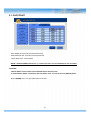
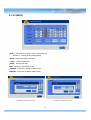
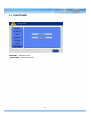
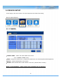
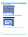
SP-VDP-400
Digital Video Recorder
USER’S MANUAL
WARNING
RISK OF ELECTRIC SHOCK
DO NOT OPEN
WARNING: TO REDUCE THE RISK OF ELECTRIC SHOCK,
DO NOT REMOVE COVER (OR BACK).
NO USER-SERVICEABLE PARTS INSIDE.
The lightning flash with arrowhead symbol, within an equilateral triangle, is intended to alert the user to the presence
of uninsulated “dangerous voltage” within the product’s enclosure that may be of sufficient magnitude to constitute
a risk of electric shock.
The exclamation point within an equilateral triangle is intended to alert the user to the presence of important
operating and
Maintenance (servicing) instructions in the literature accompanying the appliance.
COMPLIANCE NOTICE OF FCC:
THIS EQUIPMENT HAS BEEN TESTED AND FOUND TO COMPLY WITH THE LIMITS FOR A CLASS A DIGITAL
DEVICE, PURSUANT TO PART 15 OF THE FCC RULES. THESE LIMITS ARE DESIGNED TO PROVIDE
REASONABLE PROTECTION AGAINST HARMFUL INTERFERENCE WHEN THE EQUIPMENT IS OPERATED
IN A COMMERCIAL ENVIRONMENT. THIS EQUIPMENT GENERATES, USES, AND CAN RADIATE RADIO
FREQUENCY ENERGEY AND IF NOT INSTALLED AND USED IN ACCORDANCE WITH THE INSTRUCTION
MANUAL, MAY CAUSE HARMFUL INTERFERENCE TO RADIO COMMUNICATIONS. OPERATION OF THIS
EQUIPMENT IN A RESIDENTIAL AREA IS LIKELY TO CAUSE HARMFUL INTERFERENCE, IN WHICH CASE
USERS WILL BE REQUIRED TO CORRECT THE INTERFERENCE AT THEIR OWN EXPENSE.
CAUTION: CHANGES OR MODIFICATIONS NOT EXPRESSLY APPROVED BY THE PARTY RESPONSIBLE
FOR COMPLIANCE COULD VOID THE USER’S AUTHORITY TO OPERATE THE EQUIPMENT.
THIS CLASS OF DIGITAL APPARATUS MEETS ALL REQUIREMENTS OF THE CANADIAN INTERFERENCECAUSING EQUIPMENT REGULATIONS.
The information in this manual is believed to be accurate as of the date of publication. The
information contained herein is subject to change without notice. Revisions or new editions to this
publication may be issued to incorporate such changes.
1
IMPORTANT SAFEGUARDS
1. Read Instructions
13. Damage requiring Service
All the safety and operating instructions should be read before the
The manufacturer as such additions may result in the risk of fire,
Unplug this equipment from the wall outlet and refer servicing to
qualified service personnel under the following conditions:
A. When the power-supply cord or the plug has been damaged.
B. If liquid is spilled, or objects have fallen into the equipment.
C. If the equipment has been exposed to rain or water.
D. If the equipment does not operate normally by following the
operating instructions, adjust only those controls that are covered by
the operating instructions as an improper adjustment of other
controls may result in damage and will often require extensive work
by a qualified technician to restore the equipment to its normal
operation.
E. If the equipment has been dropped, or the cabinet damaged.
F. When the equipment exhibits a distinct change in performance —
this indicates a need for service.
electric shock or other personal injury.
14. Replacement Parts
appliance is operated.
2. Retain Instructions
The safety and operating instructions should be retained for future
reference.
3. Cleaning
Unplug this equipment from the wall outlet before cleaning it. Do not
Use liquid aerosol cleaners. Use a damp soft cloth for cleaning.
4. Attachments
Never add any attachments and/or equipment without the approval of
When replacement parts are required, be sure the service technician
has
used replacement parts specified by the manufacturer or that have the
same characteristics as the original part. Unauthorized substitutions
may result in fire, electric shock or other hazards.
5. Water and/or Moisture
Do not use this equipment near water or in contact with water.
6. Accessories
Do not place this equipment on an unstable cart, stand or table. The
15. Safety Check
equipment may fall, causing serious injury to a child or adult, and
follow the manufacturer’s instructions, and should use a mounting kit
Upon completion of any service or repairs to this equipment, ask the
service technician to perform safety checks to determine that the
equipment is in proper operating condition.
approved by the manufacturer.
16. Field Installation
serious damage to the equipment. Wall or shelf mounting should
7. Power Sources
This installation should be made by a qualified service person and
should conform to all local codes.
This equipment should be operated only from the type of power source
17. Correct Batteries
Indicated on the marking label. If you are not sure of the type of power,
Warning: Risk of explosion if battery is replaced by an incorrect type.
Dispose of used batteries according to the instructions.
please consult your equipment dealer or local power company.
18. Tmra
8. Power Cords
A manufacturer’s maximum recommended ambient temperature
(Tmra) for the equipment must be specified so that the customer and
installer may determine a suitable maximum operating environment
for the equipment.
Operator or installer must remove power and TNT connections before
handling the equipment.
9. Lightning
19. Elevated Operating Ambient Temperature
For added protection for this equipment during a lightning storm, or
If installed in a closed or multi-unit rack assembly, the operating
ambient temperature of the rack environment may be greater than
room
ambient. Therefore, consideration should be given to installing the
equipment in an environment compatible with the manufacturer’s
maximum rated ambient temperature (Tmra).
when it is left unattended and unused for long periods of time, unplug it
from the wall outlet and disconnect the antenna or cable system. This
will prevent damage to the equipment due to lightning and power-line
surges.
10. Overloading
20. Reduced Air Flow
Do not overload wall outlets and extension cords as this can result in
11. Objects and Liquids
Installation of the equipment in the rack should be such that the
amount
of airflow required for safe operation of the equipment is not
compromised.
Never push objects of any kind through openings of this equipment as
21. Mechanical Loading
They may touch dangerous voltage points or short out parts that could
Mounting of the equipment in the rack should be such that a
hazardous
condition is not caused by uneven mechanical loading.
the risk of fire or electric shock.
Result in a fire or electric shock. Never spill liquid of any kind on the
Equipment.
22. Circuit Overloading
12. Servicing
Consideration should be given to connection of the equipment to
supply circuit and the effect that overloading of circuits might have on
over current protection and supply wiring. Appropriate consideration
of equipment nameplate ratings should be used when addressing this
concern.
Do not attempt to service this equipment yourself. Refer all servicing
to qualified service personnel.
23. Reliable Earthing (Grounding)
Reliable grounding of rack mounted equipment should be maintained.
Particular attention should be given to supply connections other than
direct connections to the branch circuit (e.g., use of power strips).
2
INDEX
----------------------------------------------
6
-------------------------------------------------
6
---------------------------------------------------------
6
----------------------------------------------
7
-----------------------------------------------------------
8
---------------------------------------------------------
8
-----------------------------------------------
9
----------------------------------------------
10
3.1 Front Panel
---------------------------------------------------------
10
3.2 Real Panel
---------------------------------------------------------
14
----------------------------------------------------
16
---------------------------------------------------------------
17
--------------------------------------------------------
17
----------------------------------------------------
18
4.1.2 Bottom Menu
-------------------------------------------------
18
4.1.3 CAMEO Menu
-------------------------------------------------
19
--------------------------------------------------------------
22
----------------------------------------------------
22
------------------------------------------------------
23
----------------------------------------------------
24
---------------------------------------------------------
24
5.1.4 MONITOR
------------------------------------------------------
26
5.1.5 ACCOUT
------------------------------------------------------
27
5.1.6 CONFIG
------------------------------------------------------
28
----------------------------------------------------
29
1. SAFETY CAUTIONS
1.1 Power Source
1.2 Installation
1.3 Cleaning and Usage
2. OUTLINE
2.1 Functions
2.2 System Organization
3. DVR ORGANIZATION
3.3 Remote Controller
4. LIVE
4.1 Live Screen
4.1.1 Top Menu
5. SETUP
5.1 SYSTEM SETUP
5.1.1 GENERAL
5.1.2 ALARM OUT
5.1.3 DISK
5.1.7 SHUTDOWN
3
INDEX
-----------------------------------------------------
30
-------------------------------------------------------
30
-----------------------------------------------------------
31
----------------------------------------------------------
32
-----------------------------------------------------
33
--------------------------------------------------
34
-------------------------------------------------------
35
5.3.1 MOTION
-------------------------------------------------------
35
5.3.2 ALARM IN
-------------------------------------------------------
38
----------------------------------------------------
39
5.3.4 SYSTEM
-------------------------------------------------------
40
5.3.5 DISPLAY
-------------------------------------------------------
41
----------------------------------------------------
42
----------------------------------------------------
42
-----------------------------------------
43
--------------------------------------------------------
45
-------------------------------------------------------
45
----------------------------------------------------
46
-----------------------------------------------------
46
--------------------------------------------------------
48
----------------------------------------------------------
49
--------------------------------------------------------
50
----------------------------------------------
51
----------------------------------------------------
51
5.6.2 STATUS
-------------------------------------------------------
52
5.6.3 VERSION
-------------------------------------------------------
53
5.2 DEVICE SETUP
5.2.1 CAMERA
3.2.2 PTZ
5.2.3 SPOT
5.2.4 SEQUENCE
5.2.5 PRIVATE ZONE
5.3 EVENT SETUP
5.3.3 VIDEO LOSS
5.4 RECORD SETUP
5.4.1 RESOLUTION
5.4.2 SCHEDULE & RECORD
5.4.3 AUDIO
5.4.4 MANUAL
5.5 NETWORK SETUP
5.5.1 NETWORK
5.5.2 SERIAL
5.5.3 DDNS
5.5.4 E-MAIL
5.6 SYSTEM INFORMATION
5.6.1 SYSTEM LOG
4
INDEX
6. SEARCH
-------------------------------------------------------------
54
-------------------------------------------------------
55
6.1.1 Search Menu
--------------------------------------------------
56
6.1.2 Calendar Search
--------------------------------------------------
56
6.1.3 Event Search
--------------------------------------------------
57
6.1.4 Overlapped List
--------------------------------------------------
58
------------------------------------------------
59
----------------------------------------------------
59
---------------------------------------------
60
-------------------------------------------------------------
62
---------------------------------------------
63
-----------------------------------------------------------
64
-----------------------------------------------
64
-----------------------------------------------------
65
6.1 Search Screen
6.1.5 Panorama Search
6.1.6 Smart Search
6.1.7 Section Repeat Search
7. BACKUP
7.1 Playback with backup data
8. APPENDIX
8.1 Specification
8.2 Trouble Shooting
5
1. SAFETY CAUTIONS
※ Follow these instructions to keep the user safe and prevent property damage.
Read them carefully before the use of the product.
The responsibility falls on the user to install and use the product properly.
1.1 Power Source-related
1.2 Installation-related
① Insert the power plug fully and firmly into the
power source.
- Unstable connection may cause fire.
① Do not place candlelight or cigarette light on top of
the product or do not install the product near
heating devices.
- It may cause fire.
② Do not use a damaged power cord, plug or loose
outlet.
- It may cause electric shock or fire.
② Do not place the power cord near heating devices.
- The exterior of the cord may peeled off, causing
electric shock or fire.
③ Do not plug several devices exceeding the rated
capacity into a single outlet.
- Abnormal heat generation at the outlet may
cause fire.
③ Do not install the product in a place where a large
amount of oil, smoke or moisture exists. Do not
install the product in a vehicle or a place where
water is splashed.
- It may cause electric shock or fire.
④ Do not bend nor pull the power cord. Do not
place a heavy object on top of it.
- It may cause electric shock or fire.
④ Do not place the product on top of an unstable cart,
stand or table. Do not block the air ventilation with
table cloth or curtain.
- Internal temperature rise may cause fire.
⑤ When unplugging the power cord, do not pull it
out by touching the cord area or do not touch it
with a wet hand.
- It may cause electric shock or fire.
⑤ Do not install the product in a narrow place. Keep
the product a certain distance away from the wall.
- Internal temperature rise may cause fire.
6
1.3 Cleaning and Usage-related
⑥ When cleaning the product, unplug the power
cord and gently wipe using a soft cloth. Do not
directly spray water on the product or do not use
benzene, thinner or alcohol when cleaning.
① Un p lu g the p o wer p l ug du rin g li ghtn in g ,
thunderstorm or when not in use for long periods
of time.
- It may cause electric shock or fire.
- It may cause electric shock or fire.
② When taking the battery out from the remote
control, keep them away from children to prevent
from swallowing incidents.
Keep the battery away from babies.
– If a child swallowed the battery, immediately
consult a doctor.
⑦ When replacing the battery, be sure to check the
correctness of the polarity (+,-).
- If the battery polarity is wrong, generation of abnormal
heat or leakage of internal liquid may cause fire, injury
or contamination in the surrounding area.
③ Do not place the container or base filled with
water, liquids, chemicals, small piece of metal
and heavy object on the product.
- If liquid flows into the product, it may cause
electric shock or fire. A heavy object may drop
from the top of the product, causing injury.
⑧ In case the product was dropped or the case was
damaged, switch off the product and unplug the
power cord. Have a technician repair the product.
- If the damaged product is used without repair, it may
cause electric shock.
⑨ Do not repair or disassemble the product by
yourself or do not connect other connection
devices without the manufacturer’s approval.
④ Do not use or store the product near combustible
sprays and other flammable substances.
- It may cause explosion or fire.
- If repair is required, contact the reseller. Failure to
follow this instruction may cause electric shock or fire.
⑤ If dust or water is present at the power plug’s pin
and contact area, wipe out the area.
- may cause electric shock or fire.
7
2. OUTLINE
2.1 Functions
This DVR provide superior video image quality on Live view and Playback.
• Pentaplex Operation Performance (Live, Recording, Playback, Backup, Network)
• Up to maximum 16 channel composite input ports depending on model.
• Various Recording mode. (Manual / Schedule / Event)
• Various Search functions. (Date/Hour search, Calendar search, Event Search)
• Various Playback functions. (Normal / Fast / Slow / Step / Reverse / Smart / Panorama / Repeat)
• Overwrite Recording function.
• The DVR menu structure and on screen display is presented in a simple to use and logical GUI format.
• Support 16channel Audio.
• Support Mouse control.
• E-mail function (Alarm, Motion detection, Video loss, HDD fail and etc.)
8
2.2 System Organization
SMS
CAMERA
HDMI/VGA
MONITOR
KEYBOARD
CONTROLLER
SMS
Network
Alarm
Out
CAMERA
Video
input
Sensors
Input
SIREN
PTZ
SENSOR
9
3. DVR ORGANIZATION
3.1 Front Panel Description
NOTE: Turn on the DVR after connecting the power cord, camera input and monitor completely
▪ SP-VDP-400 Front
REMOVABLE HDD RACK
DVD_RW
Menu
Power LED
Number(1~0)
Playback
2 x USB
IR receiver
10
※ Front Button
The front panel of DVR is similar as normal VCR or Multiplexer and the functions are also similar .
Front buttons have various functions and are used for DVR initial setting and others.
Please refer to the below explanation.
NUMBER buttons (1 ~ 0)
Displayed selected camera number to full screen.
And also these buttons are used to enter a password.
FUNCTION button
Select function in PTZ operation mode.
LIVE button
Change mode from search or playback mode to live mode.
ZOOM / IRIS / FOCUS button
Zoom, iris, focus control mode. Press to change modes.
+ / - button
Increase of decrease the zoom, iris, or focus parameter.
BACKUP button (PTZ PRESET)
Enter backup menu. Return to previous screen if this button is pressed again. Back to live mode by
pressing “LIVE” button. In PTZ mode, it is used preset function button.
SEARCH button (ROTATE)
Enter search menu. Return to previous screen if this button is pressed again. Back to live mode by
pressing “LIVE” button. In function mode, it is used display sequencing function.
INSTANT (Key) button
Start recording when this button is pressed in live mode. In function mode, it is used to button lock
function.
SETUP button
Enter Setup menu. User need to Admin access permission. Return to previous screen if this button is
pressed again.
PANO-RAMA button
In playback mode, it is used to start panorama function.
EXIT button
Exit setup mode and return to previous screen.
11
PTZ button
Enter PTZ mode.
SMART button
Start smart search function.
REPLAY button
Start playback function.
Direction Buttons (▲, ▼, ◀, ▶ )
This buttons are used when move to other menu or change the position of the CAMEO screen.
In PTZ mode, it is used PAN/TILT function.
▲ : In Playback mode, it is Panorama search function button.
In PTZ mode, it is used to move the camera to up.
▼ : In Playback mode, it is Smart search function button.
In PTZ mode, it is used to move the camera to down.
◀ : In Playback mode, it is reverse play button and when paused screen,
user can see each frame if this button is pressed manually.
In PTZ mode, it is used to move the camera to left.
▶ : In Playback mode, it is forward play button and when paused screen,
use can see each frame if this button is pressed manually.
In PTZ mode, it is use to move to camera to right.
NOTE: For the Smart search, recording data should be recorded by the Event recording.
Otherwise, if user try to playback with Smart search, the screen is returned to live mode.
FAST REVERSE PLAY button (PTZ)
Playback with fast reverse. Playback speed is changed if this button is pressed repeatedly.
(◀, ◀◀, ◀◀◀, ◀◀◀◀, ◀◀◀◀◀). In PTZ mode, it is used to Zoom out function button.
In live mode, switch to PTZ mode by this button.
FAST FORWARD PLAY button (PLAY)
Playback with fast forward. Playback speed is changed if this button is pressed repeatedly.
(▶, ▶▶, ▶▶▶, ▶▶▶▶, ▶▶▶▶▶). In PTZ mode, it is used to Zoom in function button.
In live mode, the last portion of recorded video is played.
※ USB 2.0 Port
For USB mouse ,firmware upgrade and data backup by inserting USB memory stick with this port.
12
3.2 Rear Panel
▪ SP-VDP-400 rear
6
1
1
2
DC adapter socket
2
4
4
3
Network
3
HDMI Output
5
VGA Output
6
RS-485,
1 Alarm out,
4 Sensor Input,
13
5
4 Audio in 1 Out
HD-SDI camera
input
3.3 Remote Controller
ID
NUMBER
MUTE
OSD ON/OFF
UP Direction Key
LEFT Direction Key
RIGHT Direction Key
DOWN Direction Key
ENTER
ESC
MENU
BACKUP
SETUP
STATUS
DISPLAY
FREEZE
SQEUENCE
PTZ
ZOOM
PANIC RECORDING
PLAYBACK CONTROL
ALARM SETUP
SPOT SETUP
※ How to set ID
① Before setup the ID, Enter to the GENERAL SETUP and set the ID first. (Default is 0)
② While pressing and holding the ID button, enter the unit address of the DVR by two-digit.
③ If the unit address is a single digit, enter two digit number by adding the number 0 as the first digit.
( Example – If the unit address is 1, the input value is 01.)
※ A single remote controller can change ID from 0 to 19 and independently control up to 20 DVRs.
14
4. LIVE
4.1 Live Screen
Execution Information Message
Camera Name
Record Status
Icon
Live Screen
PTZ Control
Information
Screen
Expand/Reduction
Window
Backup Progress
Status(%)
Current Date and
Time
Current Channel
Information Icon
Current Event Information
Icon
Sequence Icon
- Record Icon (Red)
When record in live screen.
- Video-loss Icon
When there is no video input.
- Time Icon
When record by designated time.
- Audio Icon
When sound is generated in live mode.
- Motion Icon
When motion is occurred.
- Freeze Icon
When live is paused.
- Sensor Icon
When sensor is occurred.
- Sequence Icon
When screen is rotated continuously.
15
4.1.1 Top Menu
In live screen, if ▲ button of the remote controller or front panel is pressed, or if the mouse cursor
is placed over the end of the top area, the top menu is appeared.
4.1.2 Bottom Menu
In Live screen, if ▼ button of the remote controller or front panel is pressed, or if the mouse cursor is placed
over the end of the bottom area, the bottom menu is appeared.
1
4
7
9
16
10
13
16
4.1.3 CAMEO Menu
In live screen, if the ENTER button of the remote controller or front panel is pressed, a blue square cursor
will be appeared. If the ENTER button is pressed again, the CAMERA menu will be appeared.
▪ CAMEO CHANGE : The live camera can be changed to the selected channel.
If the camera number is selected at the pop-up menu shown below, the camera
is changed to the selected channel.
▪ FREEZE : Live screen of the selected channel can be paused.
▪ FREEZE ALL : Live screen of the all channels can be paused.
▪ SEQUENCE : Live screen is rotated.
17
▪ PTZ : PTZ Camera should be installed otherwise the PTZ menu is not activated.
The following picture will be appeared when select PTZ menu.
※ Using Mouse : On the above menu, when click the right button of mouse, the control screen for Menu,
Zoom, Focus and Iris will be appeared.
Zoom
Focus
Iris
※ Using Remote Controller or Front Key : The below Hot Key is available.
- Press the ENTER button on PTZ Camera channel.
- Press the ENTER button again then the CAMEO menu will be appeared.
- Select PTZ menu on the Live CAMEO menu.
- Press the ENTER button again, the above PTZ menu screen will be appeared.
- Zoom Control : In PTZ mode, press the Zoom (Back) button.
Zoom in - Fast reverse play button / Zoom out - The fast forward play button.
- Focus Control : In PTZ mode, press the Focus (Search) button.
(+) - Fast reverse play button / (-) – Fast forward play button.
- Iris Control : In PTZ mode, press the Iris (Pause) button.
(+) – Fast reverse play button / (-) – Fast forward play button.
18
- SPEED SETUP : Set the PTZ camera speed. ( 1 to 8)
NOTE: If the mouse is used to move the PTZ camera, the movement speed depends on the position
of the mouse. As the mouse pointer moves away from the center, speed becomes faster.
- PRESET SETUP :
Set the preset position. If the position setup is saved, PTZ camera will be directed to the set position by
preset number.
- PRESET TOUR :
6 different preset list can be created. If the created preset lists are set to “ON”, recording is made with
preset tour.
- PATTERN SETUP :
Pattern can be created by movement, zoom, focus and iris. After pressing the BEGIN button, adjust the
PTZ camera position or zoom and then press the END button. All directions (up, down, left and right),
zoom and iris settings are recorded.
- PATTERN TOUR : PTZ camera moves according to the saved pattern.
- AUTO FOCUS / POWER / LIGHT :
Auto focus, power and light functions can be turned on/off on each category.
- OSD MENU : Turn on/off the OSD menu.
▪ ZOOM X2 : Zoom in x2.
▪ ZOOM X4 : Zoom in x4.
▪ ADUIO ON : Turn on/off Audio.
19
5. SETUP
In this category, there are SYSTEM, NETWORK, DEVICE, RECORD and EVENT.
On the Top menu, select the [SETUP] menu icon.
After select the icon, the following LOGIN window will be appeared.
Enter the password by the key buttons and press
the OK button.
(The default password : 1)
5.1 SYSTEM SETUP
In this category, there are General, Alarm, Disk, Monitor, Account, Configuration and Shutdown.
Select the [SYSTEM] menu.
20
5.1.1 GENERAL
[SYSTEM]
▪ LANGUAGE : Select the language.
(English, Germany, French, Spanish, Japanese, Chinese, Italian, Russian, Dutch and Korean)
▪ KEY TONE : Turn on/off the buzzer sound of key.
▪ UNIT ADDRESS : Set the DVR ID.
This ID can be used when use multi DVR in same place by one remote controller.
▪ BASE CAMERA NO. : Set the beginning number of camera.
If set this value to 17, the camera number start with 17.
▪ MENU TIMEOUT : Keep the Menu screen for this value then escape from Menu.
▪ RECORD RETENTION : Prohibit the playback of passed data.
(Select 0 to 99 days. If set 3 days, can not playback the data that elapsed 3 days.
▪ BACKUP CONFIRM : Confirm the backup process.( Log-in process)
▪ HDD OVERWRITE : Select on/off to overwrite data on Hard disk.
NOTE: If set to [OFF], recording will be stopped automatically when disk is full.
21
5.1.1 GENERAL
[DATE / TIME]
▪ DATE FROMAT : Select the data format.
(YY/MM/DD) / (MM/DD/YY) / (DD/MM/YY)
▪ TIMEZONE : Select the timezone and DST.
The city which don’t use DST is set to [OFF] automatically.
▪ DATE DISPLAY : Display date on live screen or not.
▪ DATE / TIME : Change date and time.
▪ NTP : Select the usage of NTP setting.
DVR time is synchronized with NTP server and get the standard time.
The default server is [pool.ntp.org] and User can input other server.
[Sync now] : Synchronize immediately.
[Auto Sync] : Synchronize every day automatically.
▪ HOLIDAY : Add or delete holiday.
22
5.1.2 ALARM OUT
▪ SIGNAL : Select on/off to use alarm by channel.
▪ ALARM SET TEST : Check the alarm connection whether it works properly or not.
Press the [SET] button then alarm device will be operated.
▪ ALARM CLEAR TEST : Press the [CLEAR] button then alarm device will not be operated.
5.1.3 DISK
※ NOTE :
When install HDD first time,
after install HDD, should
format by the [INSTALL]
button.
[INSTALL] - Display initial HDD install and information.
23
[CHECK / USB]
▪ RECORD START TIME : Display the earliest recorded data information.
▪ RECORD END TIME : Display the latest recorded data information.
▪ DISK CHECK : Check the data from the earliest recorded to the latest recorded.
▪ USB RESET : Reset the USB connection.
▪ USB FORMAT : Format the connected USB.
24
5.1.4 MONITOR
▪ HDMI : Select the resolution for connected monitor.
▪ FILTER :
▪ BORDER COLOR : Change the border color.
▪ ALPHA BLENDING : Set the transparency of menu.
(Set 1 to 20 and 20 is closer to the more transparent.)
▪ DISPLAY POSITON :
[ HDMI selected screen]
[ALPHA BLENDING selected screen]
25
5.1.5 ACCOUNT
※ Add / delete any user and give permission freely.
※ When add new user, have to input new password.
When delete user, confirm again.
NOTE: ( Default ADMIN password is 1), Initial user name can be modified but can not delete.
CAUTION:
Default Admin account must not be deleted before add new user.
If delete default Admin user before add new Admin user, can not access on [SETUP] menu.
※ By the [PERM] menu, can give permission to each ID.
26
5.1.6 CONFIG
▪ SLOT : Select the slot to load or save on DVR memory.
※ DEFAULT : Change factory default setting.
▪ DATE : Display the latest saved date.
▪ LOAD : Load the saved data.
▪ SAVE : Save the set data.
▪ DEL : Delete the saved data on Slot.
▪ EXPORT : Export the set data to USB or DVD.
▪ IMPORT : Import the set data to USB or DVD.
[IMPORT selected screen]
[EXPORT selected screen]
27
5.1.7 SHUTDOWN
▪ RESTART : Restart the DVR.
▪ SHUTDOWN : Shutdown the DVR.
28
5.2 DEVICE SETUP
In this category, there are Camera, PTZ, Spot, Sequence and Private Zone setting.
Select the [DEVICE] Menu.
5.2.1 CAMERA
▪ CAMERA LABEL : Select the camera label of live screen.
(ALL / NUMBER / NAME / OFF)
▪ NAME : Change the camera name. ( If select the camera name, the virtual keyboard will be appeared.)
▪ INSTALL : Select On/Off button to use camera.
▪ HIDDEN : Select On/Off button to hide camera on live view. ( Record works correctly.)
NOTE: If select [INSTALL] – [OFF], Camera name and number are not displayed.
29
If select the camera name,
the virtual keyboard will be appeared.
Max camera name should be less than
11 character.
[Virtual Keyboard]
5.2.2 PTZ
[PTZ]
▪ PORT : Select the Baud Rate for using PTZ camera.
▪ ADDRESS : Select the ID for using PTZ camera.
▪ PROTOCOL : Show the PTZ protocol list.
NOTE : baud rate, data bit, parity, stop bit, ID and protocol depend on PTZ camera for using.
CAUTION : When connect the camera on the RS-485 port, refer to the manual of camera manufacturer.
30
5.2.3 SPOT
CAMERA : Select the camera for display on spot monitor.
DEFAULT : Select the camera for display on spot monitor when sequence is off.
SEQUENCE : Select On/Off for sequence screen.
DWELL : Select the interval time to move next channel. The max value is 256 sec.
POPUP : Select On/Off for pop-up screen when event is occurred.
* Exception : SVM-2004HDL dose not support SPOT.
[CAMERA selection screen]
[INTERVAL selection screen]
31
5.2.4 SEQUENCE
PAGE DWELL TIME : Select the dwell time to move next channel.
CAMEO DWELL TIME : Select the dwell time for CAMEO sequence.
NOTE: CAMEO sequence means selected camera is rotated in select cameo of division screen.
Camera image which is shown on the other CAMEO of division screen is not included in
CAMEO sequence.
[DWELL-TIME selected screen]
[CAMERA SELECT screen]
32
5.2.5 PRIVATE ZONE
▪ ZONE ENABLE : Select On/Off to use. (LIVE mode/ SEARCH mode)
▪ ZONE COLOR : Select the color to hide.
▪ ZONE : Select the zone to hide.
(When select the ZONE button, the camera image will be appeared.
NOTE : Move the blue dot to a desired location and press the OK button.
Drag and move it to include the desired area and press the OK button.
As a result, the area is covered and hidden with the selected color
TIP : On the screen, if click the right button of mouse, a menu will be appeared.
Using this menu, a selected area can be delete or saved, or returned previous menu.
[ZONE selected screen]
[Mouse right button selected screen]
33
5.3 EVENT SETUP
In this menu, there are Motion, Alarm in, Video Loss, System and Display setup.
Select the [EVENT] menu.
5.3.1 MOTION
[INPUT]
▪ ACTIVE : Select On/Off to activate motion.
▪ LEVEL : Select the sensitive for motion trigger. (Select 1 to 5 level)
▪ AREA : Select the motion area.
TIP: If select the ACTIVE+ / LEVEL+ / AREA+ menu, can change all setting at once.
34
▪ AREA SETUP
In the Area setup, the Red square is shown at the top left side of the screen. If select the OK button, the dot
color will be changed to Green. A motion area can be selected by the direction buttons.
NOTE : When the status is Red square, can move any direction to select.
When the status is Green color, can select motion area or cancel the set area.
After set the motion area, if select the MENU button, the following screen will be appeared.
▪ SELECT ALL : Select all motion area.
▪ CLEAR ALL : Clear all motion area.
▪ SAVE : Save the changed setting.
▪ CLOSE : Close the pop-up screen.
▪ EXIT : Exit the motion area setup.
35
[ACTION]
▪ RECORD : Select the channel for record.
▪ ALARM : Select On/Off for alarm.
▪ BUZZER : Select On/Off for buzzer.
▪ PRESET : Set the preset number.
(When motion is triggered, the PTZ camera move to the set preset number position)
▪ E-MAIL : Select On/Off for e-mail notification.
TIP: If select to the [DEFAULT], only record the channel which is occurred event.
36
5.3.2 ALARM IN
TIP:
If select the ACTIVE+ / TYPE+
menu, can change all setting at
once.
[INPUT]
▪ ACTIVE : Select On/Off to activate alarm.
▪ NAME : Type any name.
▪ TYPE : Select the alarm type. (NO : Normal Open / NC : Normal Close)
[ACTION]
▪ RECORD : Select the channel for record.
▪ ALARM : Select On/Off for alarm.
▪ BUZZER : Select On/Off for buzzer.
▪ PRESET : Set the preset number.
(When motion is triggered, the PTZ camera move to the set preset number position)
▪ E-MAIL : Select On/Off for e-mail notification.
37
5.3.3 VIDEO LOSS
TIP:
If select the ACTIVE+ menu,
can change all setting at once.
[INPUT]
▪ ACTIVE : Select On/Off to activate.
[ACTION]
▪ RECORD : Select On/Off for record.
▪ ALARM : Select On/Off for alarm.
▪ BUZZER : Select On/Off for buzzer.
▪ PRESET : Set the preset number.
(When motion is triggered, the PTZ camera move to the set preset number position)
▪ E-MAIL : Select On/Off for e-mail notification.
38
5.3.4 SYSTEM
[WARNING]
▪ CHECK INTERVAL : Select the check interval. (Select 1 hour to 24 hour)
▪ DISK WARNING : Select how to give a warning if disk error. (OFF, POPUP, POPUP + BUZZER)
▪ THRESHOLD : Critical value for Warning
▪ CURRENT TEMP. : Current temperature of the system
[DISK]
▪ DISK FULL WARNING : Select ON/OFF to disk full warning.
▪ USED SPACE : Display the used space
▪ ALARM : Select the channel for alarm out.
▪ BUZZER : Select On/Off for buzzer.
▪ MESSAGE : Select On/Off for message.
39
[E-MAIL] – Select option On/Off for e-mail notification.
▪ POWER / MENU / LOGIN FAIL / DISK FULL / LOG IN / SMART
5.3.5 DISPLAY
▪ DISPLAY : Select display time by second. (Select 0 to 100)
▪ EVENT MESSAGE : Select On/Off to display event message.
▪ EVENT POPUP : Select On/Off to pop-up.
40
5.4 RECORD SETUP
Select the [RECORD] menu.
In this menu, there are Setup, Record, Pre/Post, Audio, Panic Setup
5.4.1 SETUP & RECORD
▪ SETUP MODE : Select the record schedule. (CONTINUOUS / SCHEDULE)
[CONTINUOUS]
▪ DAY TIME : Select the day time. (The night time is changed automatically according to the day time zone)
▪ WEEKEND : Set the weekend zone.
[DAY] / [NIGHT] / [WEEKEND]
▪ TIME : Set the recording frame and resolution by channel.
▪ EVENT : Set the event recording. (Frame / Resolution / Post recording time [5 to 100 second])
41
[SCHEDULE]
▪ Set 3 different recording setup by day and time. (SET1, SET2, SET3)
This is related with [RECORD] menu so [CUSTOM] mode should be matched with [RECORD] menu.
TIP : For SET1, SET2, SET3 recording, change the setting [SETUP MODE] to [CONTINUOUS] and
enter to the [RECORD] menu then change the setting.
[SCHEDULE selected screen]
If set to [CONTINUOUS] in [SCHEDULE] menu, the DAY / NIGHT / WEEKEND menu will be changed to
SET1 / SET2 / SET3. Also set the frame and resolution.
[RECORD] screen after select
[SCHEDULE] menu
TIP : The frame can be set by the direction button in setup screen.
42
5.4.2 EVENT PRE / POST
▪ PRE RECORD : Sets Pre-event recording time ( Max 60 second )
▪ POST RECORD : Sets Post-event recording time ( Max 100 second )
5.4.3 AUDIO
▪ RECORD : Select On/Off for audio recording by channel.
TIP: If select the RECORD+ menu, can change all setting at once.
43
5.4.4 PANIC
▪ FPS : Select the recording frame by each channel.
▪ Quality : Select the resolution by each channel.
▪ AUDIO : Select On/Off for audio recording by each channel.
44
5.5 NETWORK SETUP
In this menu, there are Network, Serial, DDNS, E-mail setup.
Select the [NETWORK] menu.
5.5.1 LAN
[SERVER]
▪ DHCP : Select On/Off for dynamic IP.
If Dynamic IP is OFF, DVR get IP address from router automatically.
▪ HOST NAME : Type any Host name.
▪ IP ADDRESS : Type IP address. (Available when DYNAMIC IP is OFF)
▪ NETMASK: Type Subnet mask. (Available when DYNAMIC IP is OFF)
▪ GATEWAY : Type Gateway. (Available when DYNAMIC IP is OFF)
▪ DNS SERVER : Type DNS server. (Available when DYNAMIC IP is OFF)
▪ CHECK INTERNET : Check internet status for use.
45
[SERVER2]
▪ DHCP : Select On/Off for dynamic IP.
▪ IP ADDRESS : Type IP address. (Available when DYNAMIC IP is OFF)
▪ NETMASK : Type Subnet mask. (Available when DYNAMIC IP is OFF)
[CLIENT]
▪ CLIENT ACCESS : Select client access options. ( ALL / RANGE )
▪ BEGIN ADDRESS / END ADDRESS (When select RANGE option, type the IP address to accept)
: Input the acceptable IP address.
▪ SMS / WEB PORT (TCP) : Select SMS / Web Port.
▪ REMOTE RESTART : Select On/Off to restart DVR at remote.
▪ REMOTE CONFIG : Select On/Off to change configuration.
46
5.5.2 SERIAL
[RS-232 INPUT SETUP]
▪ SERIAL TYPE : Select external device.
▪ MODEL : Select the protocol to use.
▪ PORT : Select the Baud Rate / DATA bit / Parity / Stop Bit.
[RS-485 INPUT SETUP]
▪ SERIAL TYPE : Select external device.
▪ MODEL : Select the protocol to use.
▪ PORT : Select the Baud Rate / DATA bit / Parity / Stop Bit.
47
5.5.3 DDNS
▪ DDNS SERVER : Select DDNS server. ( ezddns.com / dyndns.com / changeip.com )
▪ HOST NAME : Input the host name from the registered on DDNS server.
▪ USER NAME : Input the user name from the registered on DDNS server.
▪ PASSWORD : Input the password from the registered on DDNS server.
▪ ROUTHER IP : Select On/Off for sending IP information to the DDNS server.
If use any router, this setting should be [ON].
▪ STATUS : Check the connection status.
NOTE : For using DDNS server, firstly connect the DDNS server and register Host name, User name
password then input those information on above menu.
48
5.5.4 E-MAIL
[ADDRESS]
▪ SEND E-MAIL : Select On/Off for use.
▪ SCHEDULE : Set the usage time. (From : Start time / To : End time)
▪ E-MAIL ADDRESS : Input the E-mail address to receive.
[SERVER]
▪ MAIL SERVER : Select the mail server. (SMTP server / DVR System)
▪ USER NAME : Input the user name.
▪ USER E-MAIL : Input the user e-mail address.
▪ SERVER ADDRESS : Input the server address.
▪ SERVER PORT : Input the server port.
▪ LOGIN ID : Input the Login ID.
▪ LOGIN PASSWORD : Input the Login password.
49
5.6 SYSTEM INFOMATION
In this menu, there are System Log, Status, Version.
On the Top menu, select the [INFORMATION] menu icon.
5.6.1 SYSTEM LOG
▪ Check the system log by the left, right direction button.
50
5.6.2 STATUS
[DISK]
▪ Display HDD Status.
▪ CHECK SMART NOW : Check the smart.
▪ SMART INFORMATION : Show the smart information.
[RECORD]
▪ Display RECORD Status.
51
[AUDIO]
▪ Display AUDIO Status.
[CAMERA]
▪ Display CAMERA Status
52
5.6.3 VERSION
▪ Display DVR version and information.
53
6. SEARCH
On the Top menu, select the [SEARCH] menu icon.
After select the menu, the following Log-in window will be appeared.
Enter the password by the key buttons and press
the ENTER button.
(The default password : 1)
▪ QUICK SEARCH : Designated time search by User
▪ CALENDAR : Search by date and time with Calendar.
▪ EVENT SERARCH : Search by event
▪ OVERLAPPED LIST : Search the overlapped data by changing time
▪ GO TO FIRST : Search with initial saved data.
▪ GO TO LAST : Search with the latest saved data.
54
6.1 Search Screen
Execution Information Message
Camera Name
Search Information
Icon
Search Icon
Search Screen
Repeat Time
Information
Screen
Expand/Reduction
Window
Backup Progress (%)
Recorded Audio
Information Icon
Search Date/Time
6.1.1 Search Menu
When mouse cursor is placed over on the bottom side, the Search menu is appeared.
Play 1 frame backward
Fast reverse play
Jump to the End
Play 1 frame forward
Reverse play
Division Screen
Fast forward play
Play
Repeat
Pause
Jump to Start
※ As in the live screen, the top menu can be used in the search screen.
55
Exit Search mode
6.1.2 CALENDAR SEARCH
a. Select the data by the direction button.
- Recorded data is displayed the orange color.
b. Select the time by the direction button.
- After select hour, minutes will be appeared.
NOTE: The time graph color is different by the recording mode.
Continuous Recording = Blue, Audio Recording = Light Blue, Event Recording = Red.
56
6.1.3 EVENT SEARCH
▪ DATA : Select Date to search.
▪ MOTION : Select On/Off event for search.
▪ ALARM IN : Select On/Off event for search.
▪ VIDEO LOSS : Select On/Off event for search.
▪ SELECT CAMERA : Select the camera for search.
▪ VIEW SEARCH LOG : Display selected event log.
▪ HOUR : Select time period to see.
▪ PREV : Display previous page.
▪ NEXT : Display next page.
▪ GOTO : Display the image by selected event.
57
6.1.4 OVERLAPPED LIST
▪ If user change the time or applied DST (Daylight Saving Time), there will be overlapped data.
▪ After select the list, if select the [PLAY] button, can search [QUICK SEARCH] or [EVENT SEARCH].
58
6.1.5 PANORAMA SEARCH
▪ During normal search, press the [PANORAMA] button.
▪ By mouse, click the right mouse button and click the [PANORAMA] Search.
▪ Playback with frame by frame.
6.1.6 SMART SEARCH
▪ During normal search, press the [SMART] button.
▪ Find only event and playback automatically without interval.
59
6.1.7 SECTION REPEAT SEARCH
▪ During normal search, press the [LOCK] button.
When press one time, the start position is set, press one more time, the end position is set.
▪ By mouse, click the below red circle button.
▪ Only playback the set section repeatedly.
▪ In search screen, display the following mark.
60
※ Button Explanation in Search mode
▪ Remote Controller or Front button
Button
SEARCH
ESC
ENTER
Explanation
Display the [SEARCH] menu.
Cancel the Search mode or return to the live screen.
Select the CAMEO menu.
FAST REVERSE
When reverse play, up and down play speed.
FAST FORWARD
When forward play, up and down play speed.
PAUSE
Pause the playback.
FORWARD PLAY
Playback the data.
REVEERSE PLAY
Reverse Play the data.
DISPLAY
Display division screen. (1,4,9,16)
61
7. BACKUP
On the Top menu, select the [BACKUP] menu icon.
After select the menu, the following Log-in window will be appeared.
Enter the password by the key buttons and press
the ENTER button.
(The default password : 1)
▪ TARGET : Select the device to backup. (USB / DVD)
▪ FROM : Select the start date and time.
▪ TO : Select the end date and time.
▪ BACKUP TITLE : Type any title.
▪ SELECT CAMERA : Select the camera for backup
▪ EARLIEST RECORD : Display the earliest record.
▪ LATEST RECORD : Display the earliest record.
▪ REQUIRE SPACE : Display the data capacity for selected data.
▪ WRITE : Start the backup.
62
7.1 Playback with backup data
▪ After backup, the DVR Player is copied with data.
▪ Backup data only can be played on DVR Player at PC.
▪ Can export to JPEG still shot.
63
8. APPENDIX
8.1 Specification
Model
Performance
Display speed
Record spe 1080p
ed
720p
Channel
Video In
Transmission
Main display
Main display resolution
Video Out Sub-display
Spot
Audio
Input / Output
Sensor / Al
Input / Output
arm
Details
Screen
Video
Display Split
Interface
Codec
Image quality
Recording type
Storage
Record
Network
Network
120 fps
240 fps
4CH (BNC)
SP-VDL-400
SP-VDP-400
30 fps
60 fps
4CH (BNC)
HD-SDI (SMPTE 292M)
HDMI
1920x1080(P), 1920x1080(I), 1280x720(P), 1440x900
1 VGA
1 HDMI (Multi Channel Display), 1 HD-SDI (SMPTE 292M)
None
single channel fix or rotate
16 / 1
8/1
4/1
4/1
16 / 2
8/2
1, 4, 7, 9, 10, 13,
1, 4, 7, 9
16
Graphic User Interface
H.264
Highest / High / Normal / Low
4/1
4/1
1, 4
1, 4
Schedule / Continuous / Event (Motion, Alarm)
Internal
Max. 24TB (3TB x 8 HDDs) or above
eSATA support
Max. 12TB or above
Max 6TB or above
N/A
2 USB Port / PTZ camera, PTZ controller interface
Color adjustment / Position change / Freeze / 4X digital zoom (live / playback)
Adjustable GRID (22 x 15)
5 level motion detection
Hidden camera during recording
Various PTZ camera protocol / Preset up to 255 / RS 485
Blocking the private zone (live / playback)
NTP (Network Time Protocol)
Firmware update
USB / Network
S.M.A.R.T.
Type
Auto detect when HDD's problem
Motion / Sensor / Video loss
Action
Recording, E-Mail, Log, Send message to remote, Buzzer, Pop up, Alarm, PTZ preset
Pre/Post recording
Up to 60sec / 100sec
Resolution
Quality
Speed
1080p or 720p
4 levels (Highest / High / Normal / Low)
5 levels
Quick / Event search
Search by designated time / Search by event
Repeat playback
Search
& Playback Panorama search
Backup
SP-VD-400
External
Connector
USB Port / RS-485
s
Functions
Camera option
Area
Motion
Sensitivity
Hidden camera
PTZ
Private zone
System
Auto Time Sync
Event
SP-VD-1600
SP-VD-800
Pentaplex
Real time
120 fps
120 fps
240 fps
240 fps
16CH (BNC)
8CH (BNC)
Playback repeating designated time section only
Searching frame by frame (by every 16/9/4 frames at once)
Event chain playback
Search only event and playback without interval
Dual mode function
Live monitoring during playback
File format
Media
Type
Base-T
Browser
DVR format
DVD / USB device / Network
Static IP, DHCP, DDNS
10/100/1000 Mbps
CMS, Web viewer, Smart phone support (iPhone, Android, iPad)
Environment
Operating Temperature / Humidity
Dimension / Weight (without HDD)
Power requirement
0~45°C, 32~113℉ / 5~85%
440(W) x 510(D) x 130(H)mm / 14 Kg,
17.3(W) x 20.1(D) x 5.1(H)in / 30.8 lb
AC 100V - 220V (50Hz-60Hz)
64
440(W) X 430(D) X 90(H)mm /
350(W) X 260(D) X 70(H)mm /
7 kg, 17.3(W) x 16.9(D) x 3.5(H
4kg
)in / 15.4 lb
DC 12V 5A external adapter
8. APPENDIX
8.2 Trouble Shooting
SYMPTOM
No Power
No camera image
MEASURES
If the power LED is not lighted, check the below items.
- Check the power plug and outlet. (Refer to the [Cautions for safety]
- Connect the power cord to the power connector of DVR properly.
- Connect the camera cable to the DVR port properly.
- Check the connected monitor cable with DVR.
(Refer to the [Rear Panel Configuration])
- Check the camera power and lens setting.
- As this may be caused by a temporary error, restart DVR.
- As camera setting may be wrong, initialize the camera and DVR.
※ How to initialize DVR
1. Main Menu > Configuration > Default Load > O.K > O.K
!! Caution: After DVR initialization, DVR setting is returned factory default.
Need to backup the configuration before initialize DVR.
Not record on DVR
If the recording LED does not flicker, check the below items.
- HDD should have enough space otherwise could not be recorded.
- Delete data in HDD or change the [HDD OVERWRITE] setting to [ON].
(Refer to the [GENEL Setup] – [HDD OVERWRITE])
- Replace the HDD because the HDD may be failed.
- Check the recording setup.
Not connected Network
If the network LED does not flicker, check the below items.
- Check the connected hub or router.
- Check the network cable and connection.
- Check the network setup.
65
Not work remote
controller
No sound in live view
- Check the battery polarity.
- Check the remote controller ID.
(Refer to the [Remote Controller Configuration])
- Focus on the remote controller to the IR sensor.
- Use the remote controller within 7 meters from DVR.
- Change the battery.
- Check the mike and audio cable with DVR port.
(Refer to the [Real Panel Configuration])
- Check the speaker power which is connected on Audio port.
- Turn on the Audio in the CAMEO menu.
(Select the channel which is connected Audio and turn on.
※ CAMEO menu will be appear when click the right button of mouse.
No sound in search
- Set to [Audio] – [ON].
(If set to [OFF], sound is not heard during search.)
- Although the record icon is lighted, if there is no audio input,
sound is not heard.
※ Audio record can be changed [Main Menu] > [Record Setup].
Not work smart search
- For smart search, event record should be set.
- If event record is not set, when select the smart search, return to the
live screen from search mode.
66