1
Confidential
Technical manual
Ink jet printer
TM-J8000/J8000P
Issued Date
,
,
Issued by
English
400981901
Confidential
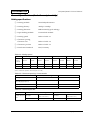
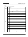
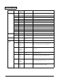
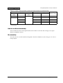
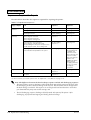
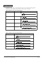
Revision Table
Revision
Page
Description
Rev. B
xii
5-4
5-8
5-10
Revision
TM-J8000 Service Utility for Windows is available. These pages are corrected to
add information for the utility.
5-9
Addition
Information has been added on transporting the printer to the service center and
back to the end user.
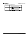
x
xi
3-18
3-19
3-20
3-21
3-22
Corrections
The level of titles are corrected.
Windows is a registered trademark of Microsoft in the U.S. and other countries.
Confidential
TM-J8000/J8000P Technical Manual
CONFIDENTIALITY AGREEMENT
BY USING THIS DOCUMENT, YOU AGREE TO ABIDE BY THE TERMS OF THIS AGREEMENT. PLEASE RETURN
THIS DOCUMENT IMMEDIATELY IF YOU DO NOT AGREE TO THESE TERMS.
❏
This document contains confidential, proprietary information of Seiko Epson Corporation or its affiliates. You
must keep such information confidential. If the user is a business entity or organization, you must limit disclosure
to those of your employees, agents and contractors who have a need to know and who are also bound by
obligations of confidentiality.
❏
On the earlier of (a) termination of your relationship with Seiko Epson, or (b) Seiko Epson’s request, you must
stop using the confidential information. You must then return or destroy the information, as directed by Seiko
Epson.
❏
If a court, arbitrator, government agency or the like orders you to disclose any confidential information, you must
immediately notify Seiko Epson. You agree to give Seiko Epson reasonable cooperation and assistance in the
negotiation.
❏
You may use confidential information only for the purpose of operating or servicing the products to which the
document relates, unless you obtain the prior written consent of Seiko Epson for some other use.
❏
Seiko Epson warrants that it has the right to disclose the confidential information. SEIKO EPSON MAKES NO
OTHER WARRANTIES CONCERNING THE CONFIDENTIAL INFORMATION OR ANY OTHER
INFORMATION ON THE DOCUMENT, INCLUDING (WITHOUT LIMITATION) ANY WARRANTY OF TITLE
OR NON-INFRINGEMENT. Seiko Epson has no liability for loss or damage arising from or relating to your use of
or reliance on the information on the document.
❏
You may not reproduce, store or transmit the confidential information in any form or by any means (electronic,
mechanical, photocopying, recording, or otherwise) without the prior written permission of Seiko Epson.
❏
Your obligations under this Agreement are in addition to any other legal obligations. Seiko Epson does not waive
any right under this Agreement by failing to exercise it. The laws of Japan apply to this Agreement.
❏
No part of this document may be reproduced, stored in a retrieval system, or transmitted in any form or by any
means, electronic, mechanical, photocopying, recording, or otherwise, without the prior written permission of
Seiko Epson Corporation.
❏
The contents of this document are subject to change without notice. Please contact us for the latest information.
❏
While every precaution has been taken in the preparation of this document, Seiko Epson Corporation assumes no
responsibility for errors or omissions.
❏
Neither is any liability assumed for damages resulting from the use of the information contained herein.
❏
Neither Seiko Epson Corporation nor its affiliates shall be liable to the purchaser of this product or third parties
for damages, losses, costs, or expenses incurred by the purchasers or third parties as a result of: accident, misuse,
or abuse of this product or unauthorized modifications, repairs, or alterations to this product, or (excluding the U.
S.) failure to strictly comply with Seiko Epson Corporation’s operating and maintenance instructions.
❏
Seiko Epson Corporation shall not be liable against any damages or problems arising from the use of any options
or any consumable products other than those designated as Original EPSON Products or EPSON Approved
Products by Seiko Epson Corporation.
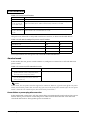
Cautions
EPSON® and ESC/POS® are registered trademarks of Seiko EPSON Corporation
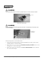
Caution
Danger of explosion if battery is incorrectly replaced. Replace only with the same or equivalent type recommended by
the manufacturer. Dispose of used batteries according to the manufacturer’s instructions.
Rev. A
i
Confidential
For Safe Repair and Maintenance Work
Key to Symbols
The symbols in this manual are identified by their level of importance, as defined below. Read
the following carefully before handling the product.
WARNING:
You must follow warnings carefully to avoid serious bodily injury.
CAUTION:
Observe cautions to avoid minor injury to your self, damage to your equipment, or loss
of data.
Note:
Notes have important information and useful tips on the operation of your equipment.
ii
Rev. A
Confidential
TM-J8000/J8000P Technical Manual
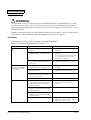
Safety Precautions
WARNING:
❏ Do not replace the fuse in the Power circuit board assembly. Replacing this fuse may
result in electric shock or fire. This fuse prevents electric shock and fire due to the
input of an abnormal power supply; it is not provided to protect the components in
the Power circuit board assembly.
Replace the entire Power circuit board assembly if the fuse blows. Other
components in the Power circuit board assembly are damaged if the fuse has
blown.
❏ Use only the indicated power voltage. Use of any other power voltage may result in
electric shock or fire.
❏ Measures to avoid electric shock:
•
Use an earthed power cable and plug it into an earthed power socket.
•
Correctly earth equipment connected to this product.
•
Disconnect the power cord and all other cables from this product before
installing the product or conducting repair or maintenance.
•
Do not perform the installation of the product, repair, or maintenance during a
lightning storm.
•
Never insert or remove the power plug with wet hands.
❏ In an abnormal status when the product produces smoke, abnormal smell, or
abnormal noise, turn off the power switch at the rear of the product and pull the
plug from the power socket. Continuing to use the product may result in electric
shock or fire. The switch on the front of the product is software controlled and may
not operate correctly in an abnormal status.
❏ If the power switch covers are attached when an abnormal status occurs,
immediately pull the plug from the power socket. Continuing to use the product
may result in electric shock or fire.
❏ Use only fuses supplied by Epson for the Main circuit board unit. Using any other fuse
may result in electric shock or fire.
Rev. A
iii
Confidential
Safety Precautions (continued)
CAUTION:
Ink Cartridge
❏ Do not put your finger inside the ink cartridge holder which contains the ink
cartridge. The ink supply needle inside the holder may cause injury.
❏ Do not shake or drop an ink cartridge that has been installed.
Ink leaking from the cartridge may get in your eyes. Also, ink stains can be impossible
to remove from clothing.
❏ If ink from the cartridge gets in your eyes, rinse immediately with clean water and
consult a doctor.
❏ Store ink cartridges out of the reach of children.
Sharp Edges
❏ The manual cutter is intended to cut paper. Pressing your fingers on the cutter may
result in injury.
❏ The autocutter blades (round blade and fixed blade) are exposed when the roll
paper cover is open. These cutter blades are intended to cut paper. Pressing your
fingers on the cutter blades may result in injury.
❏ This product contains other metal parts with sharp edges in addition to the cutters.
Pressing your fingers or hands on these parts may result in injury.
Hot Parts
❏ Some parts of the Main circuit board unit and the Power circuit board assembly may
become hot. Turn off the power at least 10 minutes before handling these parts.
Lithium Battery
❏ A lithium battery is mounted on the Main circuit board unit. Do not short the terminals
of this battery.
❏ Apply adhesive tape to insulate the terminals of a lithium battery that has been
removed. Shorting of the uninsulated terminals may result in heat generation, fire, or
explosion.
❏ Do not disassemble or modify the internal lithium battery. This may result in heat
generation, fire, or explosion.
iv
Rev. A
Confidential
TM-J8000/J8000P Technical Manual
Safety Precautions (continued)
CAUTION:
❏ Do not incinerate or heat a lithium battery that has been removed. This may result in
heat generation, fire, or explosion.
❏ Do not soak a lithium battery that has been removed in water. This may result in heat
generation, fire, or explosion.
❏ Be sure to use the specified lithium battery, and to mount the + and - polarities
correctly when connecting a lithium battery. Incorrectly connecting the battery
may result in heat generation, fire, or explosion.
❏ Danger of explosion if battery is incorrectly replaced. Replace only with the same or
equivalent type recommended by the manufacturer. Dispose of used batteries
according to the manufacturer’s instructions.
Rev. A
v
Confidential
Precautions to Protect the Product
CAUTION:
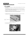
Turning Product on its Side
❏ When turning the product on its side, be sure to turn it with the ink cartridge side
facing down. Do not turn the printer upside down since it may cause ink leakage.
After turning the printer upright, check whether it prints properly.
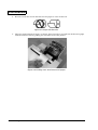
Transport
❏ Before transporting the printer, prepare it for transport as described in “Preparing for
Transport” in Chapter 5, “Repair and Troubleshooting.” Failure to prepare the
product for transport may result in defective printing or ink leakage.
❏ Replace the printer in the TM-J8000 packing case for transportation. Failure to use
the specified packing case may cause ink leakage or damage to the printer.
❏ Do not turn the printer upside down during transportation.
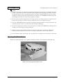
Connecting Cables
❏ Do not connect a telephone line or drawer kick connector to the customer display
connector. This may damage to the telephone circuit, printer, or drawer kick.
❏ Do not connect a telephone line to the drawer kick connector. This may result in
damage to the telephone circuit or printer.
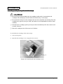
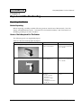
Handling the Head Nozzle, Cap and Cleaning Plate
❏ Do not touch the head nozzle, head cap and head cleaning plate with a finger or
other object. This may cause damage.
Handling the Circuit Boards
❏ To prevent damage due to static electricity, wear a wrist-band for grounding before
handling the internal printed circuit boards.
❏ To prevent damage due to static electricity, place the internal circuit boards on an
antistatic rubber mat or other antistatic-treated surface when you remove the
internal circuit boards.
❏ To prevent damage to the circuit boards, do not let them be subject to shocks or
vibrations.
❏ Do not touch the circuit board terminals or cable terminals. Contamination due to
touching the terminals may cause malfunctions.
vi
Rev. A
Confidential
TM-J8000/J8000P Technical Manual
No Chemical Solvents
❏ Do not use alcohol, benzine, thinners, trichloroethylene, or ketone-based solvents to
remove contamination. These may cause deterioration or damage to plastic and
rubber parts.
Precautions on Handling and Disposal of the Product
Note:
Extending Ink Cartridge Life
❏ The first ink charging is conducted automatically when the first ink cartridge is installed (when the
printer is turned on). Do not turn the printer power off during the charging. If the power is turned
off, the ink charging will be subsequently repeated, causing a dramatic reduction in ink cartridge
printing life. This operation takes approximately two minutes. The POWER LED blinks during the
ink charging and stays on as soon as the charging is complete.
❏ Do not remove the ink cartridge unless it is being replaced. A cleaning operation is conducted each
time the ink cartridge is removed, causing a reduction in the ink cartridge printing life.
❏ Only press the CLEANING button to clean the head if printing problems are being experienced. The
cleaning operation causes a reduction in the ink cartridge printing life.
❏ Do not turn off the power switch or open the printer cover while the POWER LED is blinking; head
cleaning or the ink charging is being conducted.
Ink Freezing
❏ The interior of the printer and ink in the cartridge freezes if placed in an environment of -8 °C (18 °F)
or colder. Approximately three hours are required before frozen ink can be used, if switched from -20
°C ( -4 °F) environment to +25 °C (77 °F) environment, for example.
Replacing the Ink Cartridge
❏ Replace the ink cartridge while the printer is turned on. If the power is off during replacement,
defective printing may occur because the ink cartridge replacement is not correctly detected.
❏ Use the EPSON SJIC1 ink cartridge. The use of any other cartridge may cause damage to the printer.
Disposal
❏ Dispose of or recycle used ink cartridges as prescribed under national and local laws.
❏ Dispose of the used printer as prescribed under national and local laws.
❏ Dispose of used lithium batteries as prescribed under national and local laws.
Rev. A
vii
Confidential
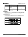
Precautions on Handling and Disposal of the Product (continued)
Ink Discharging Cartridge
❏ Do not use a used ink cartridge as the ink discharging cartridge.This may cause ink leakage.
❏ An ink discharging cartridge can be used up to 26 times. Cross out a number from the table on the
label each time the cartridge is used. Dispose of the cartridge after it is used 26 times. Excess use will
cause ink leakage.
Display Module Connector
❏ The display module connector (DM) cannot be used with a printer with parallel interface. This
connector is only available for a printer with a serial interface.
Printer Cover
❏ Immediately close the printer cover after pressing the CLEANING button to start head cleaning.
viii
Rev. A
Confidential
TM-J8000/J8000P Technical Manual
Contents
For Safe Repair and Maintenance Work . . . . . . . . . . . . . . . . . . . . . . . . . . . . . . . . . .
Key to Symbols . . . . . . . . . . . . . . . . . . . . . . . . . . . . . . . . . . . . . . . . . . . . . . . . . . .
Safety Precautions . . . . . . . . . . . . . . . . . . . . . . . . . . . . . . . . . . . . . . . . . . . . . . . . .
Precautions to Protect the Product . . . . . . . . . . . . . . . . . . . . . . . . . . . . . . . . . . . . . . .
Precautions on Handling and Disposal of the Product . . . . . . . . . . . . . . . . . . . . . .
About This Manual . . . . . . . . . . . . . . . . . . . . . . . . . . . . . . . . . . . . . . . . . . . . . . . . . . . .
Aim of the Manual . . . . . . . . . . . . . . . . . . . . . . . . . . . . . . . . . . . . . . . . . . . . . . . . .
Contents of the Manual . . . . . . . . . . . . . . . . . . . . . . . . . . . . . . . . . . . . . . . . . . . .
Related Software and Documents . . . . . . . . . . . . . . . . . . . . . . . . . . . . . . . . . . . .
ii
ii
iii
vi
vii
xii
xii
xii
xii
Chapter 1 Specifications
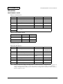
Features . . . . . . . . . . . . . . . . . . . . . . . . . . . . . . . . . . . . . . . . . . . . . . . . . . . . . . . . . . . . . .
General Specifications (for both receipt and slip) . . . . . . . . . . . . . . . . . . . . . . . . . . .
Printing specifications . . . . . . . . . . . . . . . . . . . . . . . . . . . . . . . . . . . . . . . . . . . . . .
Character specifications . . . . . . . . . . . . . . . . . . . . . . . . . . . . . . . . . . . . . . . . . . . .
Ink cartridge . . . . . . . . . . . . . . . . . . . . . . . . . . . . . . . . . . . . . . . . . . . . . . . . . . . . . .
Interface . . . . . . . . . . . . . . . . . . . . . . . . . . . . . . . . . . . . . . . . . . . . . . . . . . . . . . . . . .
DIP switches . . . . . . . . . . . . . . . . . . . . . . . . . . . . . . . . . . . . . . . . . . . . . . . . . . . . . .
Internal buffer . . . . . . . . . . . . . . . . . . . . . . . . . . . . . . . . . . . . . . . . . . . . . . . . . . . .
Electrical characteristics . . . . . . . . . . . . . . . . . . . . . . . . . . . . . . . . . . . . . . . . . . . .
Reliability . . . . . . . . . . . . . . . . . . . . . . . . . . . . . . . . . . . . . . . . . . . . . . . . . . . . . . . .
Dimensions/Weight . . . . . . . . . . . . . . . . . . . . . . . . . . . . . . . . . . . . . . . . . . . . . . .
Environmental condition . . . . . . . . . . . . . . . . . . . . . . . . . . . . . . . . . . . . . . . . . . .
EMI and safety standards applied . . . . . . . . . . . . . . . . . . . . . . . . . . . . . . . . . . .
Receipt Section . . . . . . . . . . . . . . . . . . . . . . . . . . . . . . . . . . . . . . . . . . . . . . . . . . . . . . . .
Paper feeding mechanism . . . . . . . . . . . . . . . . . . . . . . . . . . . . . . . . . . . . . . . . . .
Paper roll specification . . . . . . . . . . . . . . . . . . . . . . . . . . . . . . . . . . . . . . . . . . . . .
Autocutter . . . . . . . . . . . . . . . . . . . . . . . . . . . . . . . . . . . . . . . . . . . . . . . . . . . . . . . .
Slip Section . . . . . . . . . . . . . . . . . . . . . . . . . . . . . . . . . . . . . . . . . . . . . . . . . . . . . . . . . . .
Paper feeding mechanism . . . . . . . . . . . . . . . . . . . . . . . . . . . . . . . . . . . . . . . . . .
Slip paper (includes personal check) . . . . . . . . . . . . . . . . . . . . . . . . . . . . . . . . .
1-1
1-3
1-3
1-4
1-4
1-5
1-7
1-9
1-9
1-9
1-9
1-10
1-11
1-11
1-11
1-11
1-11
1-12
1-12
1-12
Chapter 2 Outline of Operation
M-J8000 printer mechanism . . . . . . . . . . . . . . . . . . . . . . . . . . . . . . . . . . . . . . . . . . . . .
Print mechanism . . . . . . . . . . . . . . . . . . . . . . . . . . . . . . . . . . . . . . . . . . . . . . . . . .
Roll paper feed mechanism . . . . . . . . . . . . . . . . . . . . . . . . . . . . . . . . . . . . . . . . .
Slip feed mechanism . . . . . . . . . . . . . . . . . . . . . . . . . . . . . . . . . . . . . . . . . . . . . . .
Detector mechanisms . . . . . . . . . . . . . . . . . . . . . . . . . . . . . . . . . . . . . . . . . . . . . .
Autocutter mechanism . . . . . . . . . . . . . . . . . . . . . . . . . . . . . . . . . . . . . . . . . . . . .
Ink system mechanism . . . . . . . . . . . . . . . . . . . . . . . . . . . . . . . . . . . . . . . . . . . . .
Overview of electrical circuit . . . . . . . . . . . . . . . . . . . . . . . . . . . . . . . . . . . . . . . . . . . .
Main-board Unit . . . . . . . . . . . . . . . . . . . . . . . . . . . . . . . . . . . . . . . . . . . . . . . . . .
Air pressure sensor . . . . . . . . . . . . . . . . . . . . . . . . . . . . . . . . . . . . . . . . . . . . . . . .
RTC and lithium battery . . . . . . . . . . . . . . . . . . . . . . . . . . . . . . . . . . . . . . . . . . . .
I/F board Unit . . . . . . . . . . . . . . . . . . . . . . . . . . . . . . . . . . . . . . . . . . . . . . . . . . . .
Power circuit board assembly . . . . . . . . . . . . . . . . . . . . . . . . . . . . . . . . . . . . . . .
Switch circuit board assembly . . . . . . . . . . . . . . . . . . . . . . . . . . . . . . . . . . . . . . .
Fan assembly . . . . . . . . . . . . . . . . . . . . . . . . . . . . . . . . . . . . . . . . . . . . . . . . . . . . .
Rev. A
2-1
2-2
2-6
2-9
2-16
2-26
2-29
2-33
2-34
2-37
2-37
2-37
2-37
2-39
2-39
Contents ix
Confidential
Chapter 3 Handling
Before Handling the Product . . . . . . . . . . . . . . . . . . . . . . . . . . . . . . . . . . . . . . . . . . . . 3-1
Turning the Power On or Off . . . . . . . . . . . . . . . . . . . . . . . . . . . . . . . . . . . . . . . . . . . . 3-1
Standard mode . . . . . . . . . . . . . . . . . . . . . . . . . . . . . . . . . . . . . . . . . . . . . . . . . . . . 3-2
Power switch fixed mode (power off command mode) . . . . . . . . . . . . . . . . . . 3-3
IM interlock mode . . . . . . . . . . . . . . . . . . . . . . . . . . . . . . . . . . . . . . . . . . . . . . . . . 3-3
Power switch fixed mode + IM interlock mode . . . . . . . . . . . . . . . . . . . . . . . . 3-4
Part Names and Functions . . . . . . . . . . . . . . . . . . . . . . . . . . . . . . . . . . . . . . . . . . . . . . 3-5
Installing or Replacing the Paper Roll . . . . . . . . . . . . . . . . . . . . . . . . . . . . . . . . . . . . . 3-11
Installing or Replacing the Ink Cartridge . . . . . . . . . . . . . . . . . . . . . . . . . . . . . . . . . . 3-13
Opening the Printer Cover . . . . . . . . . . . . . . . . . . . . . . . . . . . . . . . . . . . . . . . . . . . . . . 3-15
Inserting Slip Paper . . . . . . . . . . . . . . . . . . . . . . . . . . . . . . . . . . . . . . . . . . . . . . . . . . . . 3-16
Setting the DIP Switches . . . . . . . . . . . . . . . . . . . . . . . . . . . . . . . . . . . . . . . . . . . . . . . . 3-17
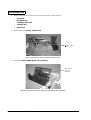
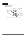
Attaching or Replacing the Power Switch Covers . . . . . . . . . . . . . . . . . . . . . . . . . . 3-17
Front power switch cover . . . . . . . . . . . . . . . . . . . . . . . . . . . . . . . . . . . . . . . . . . . 3-18
Rear power switch cover . . . . . . . . . . . . . . . . . . . . . . . . . . . . . . . . . . . . . . . . . . . . 3-18
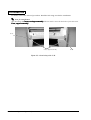
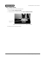
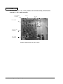
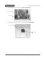
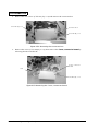
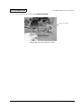
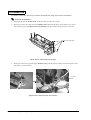
Removing Paper Jams . . . . . . . . . . . . . . . . . . . . . . . . . . . . . . . . . . . . . . . . . . . . . . . . . . 3-18
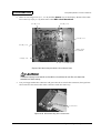
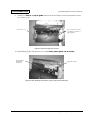
Paper jams near the head . . . . . . . . . . . . . . . . . . . . . . . . . . . . . . . . . . . . . . . . . . . 3-18
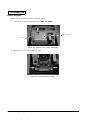
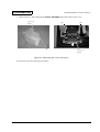
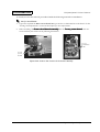
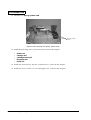
Paper jams near the autocutter . . . . . . . . . . . . . . . . . . . . . . . . . . . . . . . . . . . . . . . 3-19
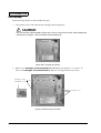
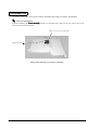
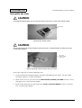
Self Test . . . . . . . . . . . . . . . . . . . . . . . . . . . . . . . . . . . . . . . . . . . . . . . . . . . . . . . . . . . . . . 3-20
Running the self test on a paper roll . . . . . . . . . . . . . . . . . . . . . . . . . . . . . . . . . . 3-20
Running the self test on slip paper . . . . . . . . . . . . . . . . . . . . . . . . . . . . . . . . . . . 3-20
Hexadecimal Dump . . . . . . . . . . . . . . . . . . . . . . . . . . . . . . . . . . . . . . . . . . . . . . . . . . . . 3-21
Starting the hexadecimal dump . . . . . . . . . . . . . . . . . . . . . . . . . . . . . . . . . . . . . . 3-21
Printing sample . . . . . . . . . . . . . . . . . . . . . . . . . . . . . . . . . . . . . . . . . . . . . . . . . . . . 3-22
Chapter 4 Maintenance and Inspection
Before Maintenance and Inspection . . . . . . . . . . . . . . . . . . . . . . . . . . . . . . . . . . . . . . 4-1
Cleaning . . . . . . . . . . . . . . . . . . . . . . . . . . . . . . . . . . . . . . . . . . . . . . . . . . . . . . . . . . . . . . 4-1
Head cleaning . . . . . . . . . . . . . . . . . . . . . . . . . . . . . . . . . . . . . . . . . . . . . . . . . . . . . 4-1
Removing stains . . . . . . . . . . . . . . . . . . . . . . . . . . . . . . . . . . . . . . . . . . . . . . . . . . . 4-1
Removing dirt and dust . . . . . . . . . . . . . . . . . . . . . . . . . . . . . . . . . . . . . . . . . . . . 4-2
Lubrication . . . . . . . . . . . . . . . . . . . . . . . . . . . . . . . . . . . . . . . . . . . . . . . . . . . . . . . . . . . 4-3
Lubrication standards . . . . . . . . . . . . . . . . . . . . . . . . . . . . . . . . . . . . . . . . . . . . . . 4-3
Lubricant types . . . . . . . . . . . . . . . . . . . . . . . . . . . . . . . . . . . . . . . . . . . . . . . . . . . . 4-3
Lubrication points . . . . . . . . . . . . . . . . . . . . . . . . . . . . . . . . . . . . . . . . . . . . . . . . . 4-3
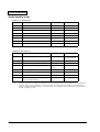
Chapter 5 Repair and Troubleshooting
Repairing the Printer . . . . . . . . . . . . . . . . . . . . . . . . . . . . . . . . . . . . . . . . . . . . . . . . . . . 5-1
Before Repairing . . . . . . . . . . . . . . . . . . . . . . . . . . . . . . . . . . . . . . . . . . . . . . . . . . . 5-1
Service tools required for this printer . . . . . . . . . . . . . . . . . . . . . . . . . . . . . . . . . 5-1
Sequences Required for Repair . . . . . . . . . . . . . . . . . . . . . . . . . . . . . . . . . . . . . . . . . . . 5-4
Ink discharging sequence . . . . . . . . . . . . . . . . . . . . . . . . . . . . . . . . . . . . . . . . . . . 5-5
Head exchange sequence . . . . . . . . . . . . . . . . . . . . . . . . . . . . . . . . . . . . . . . . . . . 5-6
Nozzle test . . . . . . . . . . . . . . . . . . . . . . . . . . . . . . . . . . . . . . . . . . . . . . . . . . . . . . . . 5-8
Preparing for transport . . . . . . . . . . . . . . . . . . . . . . . . . . . . . . . . . . . . . . . . . . . . . 5-9
Troubleshooting . . . . . . . . . . . . . . . . . . . . . . . . . . . . . . . . . . . . . . . . . . . . . . . . . . . . . . . 5-10
Symptoms . . . . . . . . . . . . . . . . . . . . . . . . . . . . . . . . . . . . . . . . . . . . . . . . . . . . . . . . 5-10
Error messages . . . . . . . . . . . . . . . . . . . . . . . . . . . . . . . . . . . . . . . . . . . . . . . . . . . . 5-11
Troubleshooting tables . . . . . . . . . . . . . . . . . . . . . . . . . . . . . . . . . . . . . . . . . . . . . 5-17
x Contents
Rev. B
Confidential
TM-J8000/J8000P Technical Manual
Chapter 6 Disassembly, Assembly, and Adjustment
Before Disassembly, Assembly, and Adjustment . . . . . . . . . . . . . . . . . . . . . . . . . . .
About this Chapter . . . . . . . . . . . . . . . . . . . . . . . . . . . . . . . . . . . . . . . . . . . . . . . . . . . .
Screws . . . . . . . . . . . . . . . . . . . . . . . . . . . . . . . . . . . . . . . . . . . . . . . . . . . . . . . . . . . . . . .
Quick Reference . . . . . . . . . . . . . . . . . . . . . . . . . . . . . . . . . . . . . . . . . . . . . . . . . . . . . . .
Disassembly and Assembly for the TM-J8000/J8000P . . . . . . . . . . . . . . . . . . . . . . .
Covers and upper case . . . . . . . . . . . . . . . . . . . . . . . . . . . . . . . . . . . . . . . . . . . . .
Mechanism assembly, M-J8000 . . . . . . . . . . . . . . . . . . . . . . . . . . . . . . . . . . . . . .
Case, lower assembly . . . . . . . . . . . . . . . . . . . . . . . . . . . . . . . . . . . . . . . . . . . . . .
Cables . . . . . . . . . . . . . . . . . . . . . . . . . . . . . . . . . . . . . . . . . . . . . . . . . . . . . . . . . . .
Circuit boards . . . . . . . . . . . . . . . . . . . . . . . . . . . . . . . . . . . . . . . . . . . . . . . . . . . . .
Fan assembly . . . . . . . . . . . . . . . . . . . . . . . . . . . . . . . . . . . . . . . . . . . . . . . . . . . . .
Disassembly and Assembly for the Mechanism Assembly, M-J8000 . . . . . . . . . .
Connector box (connector board) . . . . . . . . . . . . . . . . . . . . . . . . . . . . . . . . . . . .
Pump unit . . . . . . . . . . . . . . . . . . . . . . . . . . . . . . . . . . . . . . . . . . . . . . . . . . . . . . . .
Roll paper unit . . . . . . . . . . . . . . . . . . . . . . . . . . . . . . . . . . . . . . . . . . . . . . . . . . . .
Head unit . . . . . . . . . . . . . . . . . . . . . . . . . . . . . . . . . . . . . . . . . . . . . . . . . . . . . . . .
Cartridge frame unit . . . . . . . . . . . . . . . . . . . . . . . . . . . . . . . . . . . . . . . . . . . . . . .
Carriage unit . . . . . . . . . . . . . . . . . . . . . . . . . . . . . . . . . . . . . . . . . . . . . . . . . . . . . .
Shutter unit . . . . . . . . . . . . . . . . . . . . . . . . . . . . . . . . . . . . . . . . . . . . . . . . . . . . . . .
Paper guide, slip, lower . . . . . . . . . . . . . . . . . . . . . . . . . . . . . . . . . . . . . . . . . . . .
Assembling the Roll Paper Unit . . . . . . . . . . . . . . . . . . . . . . . . . . . . . . . . . . . . . . . . .
Assembling the NE detector sub-assembly . . . . . . . . . . . . . . . . . . . . . . . . . . . .
Assembling the paper tension roller sub-assembly . . . . . . . . . . . . . . . . . . . . .
Assembling the roll paper guide assembly . . . . . . . . . . . . . . . . . . . . . . . . . . . .
Assembling the gear train frame assembly . . . . . . . . . . . . . . . . . . . . . . . . . . . .
Assembling the slide frame and rotation frame assembly . . . . . . . . . . . . . . .
Assembling the cutter sub-unit . . . . . . . . . . . . . . . . . . . . . . . . . . . . . . . . . . . . . .
Assembling the roll paper unit . . . . . . . . . . . . . . . . . . . . . . . . . . . . . . . . . . . . . .
Assembling the Shutter Unit . . . . . . . . . . . . . . . . . . . . . . . . . . . . . . . . . . . . . . . . . . . .
Assembling the Carriage Unit . . . . . . . . . . . . . . . . . . . . . . . . . . . . . . . . . . . . . . . . . . .
Assembling the Cartridge Frame Unit . . . . . . . . . . . . . . . . . . . . . . . . . . . . . . . . . . . .
Assembling the Pump Unit . . . . . . . . . . . . . . . . . . . . . . . . . . . . . . . . . . . . . . . . . . . . .
Settings and Adjustments . . . . . . . . . . . . . . . . . . . . . . . . . . . . . . . . . . . . . . . . . . . . . . .
Platen gap adjustment . . . . . . . . . . . . . . . . . . . . . . . . . . . . . . . . . . . . . . . . . . . . .
HP adjustment . . . . . . . . . . . . . . . . . . . . . . . . . . . . . . . . . . . . . . . . . . . . . . . . . . . .
Slip hold top roller assembly gap adjustment . . . . . . . . . . . . . . . . . . . . . . . . . .
Head rank setting . . . . . . . . . . . . . . . . . . . . . . . . . . . . . . . . . . . . . . . . . . . . . . . . .
LR adjustment . . . . . . . . . . . . . . . . . . . . . . . . . . . . . . . . . . . . . . . . . . . . . . . . . . . .
6-1
6-1
6-2
6-3
6-5
6-5
6-14
6-20
6-22
6-26
6-32
6-35
6-35
6-39
6-42
6-48
6-52
6-60
6-66
6-71
6-81
6-81
6-82
6-83
6-85
6-91
6-96
6-110
6-135
6-169
6-185
6-194
6-195
6-197
6-205
6-208
6-212
6-214
Appendix
Updating the Firmware . . . . . . . . . . . . . . . . . . . . . . . . . . . . . . . . . . . . . . . . . . . . . . . .
Parts Layout . . . . . . . . . . . . . . . . . . . . . . . . . . . . . . . . . . . . . . . . . . . . . . . . . . . . . . . . . .
Parts List in A to Z Order . . . . . . . . . . . . . . . . . . . . . . . . . . . . . . . . . . . . . . . . . . . . . . .
Parts List in Reference Number Order . . . . . . . . . . . . . . . . . . . . . . . . . . . . . . . . . . . .
Overall Exploded Diagrams . . . . . . . . . . . . . . . . . . . . . . . . . . . . . . . . . . . . . . . . . . . . .
Circuit Diagrams . . . . . . . . . . . . . . . . . . . . . . . . . . . . . . . . . . . . . . . . . . . . . . . . . . . . . .
Rev. B
A-1
A-2
A-5
A-11
A-17
A-24
Contents xi
Confidential
About This Manual
Aim of the Manual
This manual was created to provide the information on printer maintenance and repair required
by technicians who handle this work.
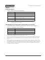
Contents of the Manual
The configuration of the manual is as follows:
Chapter 1, “Specifications”
Describes the features and basic specifications
of the product.
Chapter 2, “Outline of Operation”
Describes the basic mechanical and electrical
operations of the product.
Chapter 3, “Handling”
Describes the appropriate product handling
methods during maintenance and repair.
Chapter 4, ”Maintenance and Inspection”
Describes the maintenance and inspection items
and procedures.
Chapter 5, “Repair and Troubleshooting”
Describes the required repair items and
troubleshooting procedures.
Chapter 6,”Disassembly, Assembly, and
Adjustment”
Describes the disassembly, assembly and
adjustment procedures for the product.
Appendix
Gives reference information related to
maintenance and repairs.
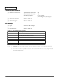
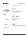
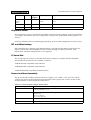
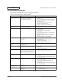
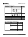
Related Software and Documents
Table 1 Related software and documents
Software/document name
Description
TM-J8000 Service Utility
This utility contains the following programs: Ink discharging
sequence program, Head exchange sequence program, and LR
adjustment sequence program, etc. To obtain the utility, contact
the Epson service center.
TM-J8000 Service Utility User's Manual
This manual describes how to use the TM-J8000 Service Utility. To
obtain the manual, contact the Epson service center.
TM-J8000/J8000P Operator’s Manual
Describes product installation and handling procedures for the
POS terminal operator.
xii Contents
Rev. B
Confidential
TM-J8000/J8000P Technical Manual
Chapter 1
Specifications
Features
The TM-J8000 is a high-quality ink-jet POS printer that can print on roll paper or on slip paper.
The printer has the following features:
❏ Low noise:
•
Low noise ink jet printing as required for high-quality restaurants
❏ High speed printing on normal paper:
•
Paper roll: approximately 15 lines/second
•
Slip paper: approximately 3 pages per minute for A4 size paper
❏ High printing quality:
•
High-quality ink jet head with 128 nozzles/360 dpi for bar code and high density
printing
❏ Easy to operate:
•
Easy paper roll loading
•
The printer’s separate functional units allow easy maintenance
•
Clear and readable icon indicators
•
One step plug-in due to built-in universal power supply
❏ Bar code printing:
•
Bar code software such as UPC-A, Code 39, and Code 128 is supported.
❏ Interface:
•
High-speed bidirectional parallel, RS-232, or RS-485 interfaces can be used.
❏ Connecting and interlocking with EPSON peripheral devices:
•
Rev. A
EPSON customer display series (DM-D102-012 or DM-D203-012) can be connected to the
serial model of the printer, and the IM 5*5 can be used with this printer.
Specifications 1-1
Confidential
❏ Ink cartridge:
•
Using a large ink cartridge enables a long time between cartridge changes and low
running cost (approximately 12,000,000 characters per cartridge with Font B continuous
printing).
❏ Internal buffer:
•
45 or 4 K receive buffer can be selected.
❏ Command protocol:
•
❏
Command protocol is based on the ESC/POS® standard.
Paper formats:
•
Narrow to wide format paper can be used—from a personal check (approximately
70 mm) to US letter (216 mm) using Font A, 36 to 130 column printing.
❏ Autocutter:
•
The autocutter uses a circular cut method with a high-quality blade and a long life
(approximately 2,000,000 cuts).
❏ Paper roll sensor:
•
Paper end and paper near-end sensors are standard.
❏ Printer driver:
•
OCX driver and Windows driver are supported.
1-2 Specifications
Rev. A
Confidential
TM-J8000/J8000P Technical Manual
General Specifications (for both receipt and slip)
Printing specifications
❏ Printing method:
Serial inkjet dot matrix
❏ Printing density:
360 dpi × 360 dpi
❏ Printing direction:
Bidirectional (logical seeking)
❏ Paper feeding method:
Friction feed method
❏ Printing speed:
Refer to Table 1-1
❏ Character spacing,
Character size:
Refer to Table 1-2
❏ Characters per line:
Refer to Table 1-3
❏ Head control method:
Fine/Economy
Table1-1 Printing speed
Slip
Receipt
Slip
Receipt
Head
control
method
Font A
65 CPL
Font B
80 CPL
Font A
20 CPL
Font B
25 CPL
Font A
130 CPL
Font B
158 CPL
Font A
42 CPL
Font B
51 CPL
Fine
6.8
10.0
11.8
16.9
4.2
6.2
9.0
13.1
Economy
7.8
11.3
12.6
18.1
4.9
7.3
10.1
14.7
(CPL: characters per line, LPS: lines per second)
Table1-2 Character spacing, character size
Font A (Default Setting)
Font B
Font type
Sans serif
Sans serif
Dot structure (W × H)
(Including Right space)
22 × 48 dots
18 × 36 dots
Right space
4 dots
2 dots
Character size
1.48 × 3.32 mm
1.20 × 2.47 mm
Table1-3 Character per line
Font A (Default Setting)
Characters per
line
Rev. A
Font B
Receipt
Slip
(68 to 215.9 mm)
Receipt
Slip
(68 to 215.9 mm)
42 characters
38 to 130 characters
51 characters
46 to 158 characters
Specifications 1-3
Confidential
Character specifications
❏ Number of characters:
Alphanumeric characters:
International characters:
Extended graphics:
❏ Character structure:
Refer to Table 1-2
❏ Character types:
Refer to Table 1-2
95
32
128 × 9 pages
(including two space pages)
Ink cartridge
❏ Type:
Exclusive ink cartridge
❏ Specifications:
Refer to Table 1-4
Table 1-4 Ink cartridge specification
Name
Ink Cartridge SJIC1
Weight (*1)
Approximately 250 g (*1)
Dimensions
39.1 × 100.2 × 139.6 mm (W × H × D)/(1.5 × 5.5 × 3.9 in.)
(Including labels/Excluding protrusion)
Case color
Transparent black
Ink color
Black
Maximum number of
printable characters
Approximately 12,000,000 characters (*2)
Effective period
Within two years after production (Normal temperature)
Notes:
(*1) The weight indicates the gross weight of the ink cartridge, with labels, not including the individual
outer box.
(*2) The maximum number of printable characters are measured with Font B (economy) using the EPSON
standard printing patterns.
1-4 Specifications
Rev. A
Confidential
TM-J8000/J8000P Technical Manual
Interface
RS-232 serial interface
Table 1-5 RS-232 serial Interface specifications
Item
Content
Data transmission
Serial
Synchronization
Asynchronous
Handshaking
DTR/DSR or XON/XOFF control
Signal levels
MARK = –3 V to –15 V
SPACE = +3 V to +15 V
Stop bits
1 or more
Connector (printer side)
Female D-SUB 25 pin connector
Logic “1”
Logic “0”
NOTES: * The data word length, baud rate, and parity depend on the DIP switch settings.
* The stop bit for the printer side is fixed to 1.
IEEE 1284 bidirectional parallel interface (Parallel interface specifications)
<Compatibility Mode> Data transmission from Host to Printer: Centronics compatible
Table 1-6 Compatibility mode specifications
Item
Content
Data transmission
8-bit Parallel
Synchronization
Externally supplied nStrobe signals
Handshaking
Ack and Busy signals
Signal levels
TTL compatible
<Reverse Mode> Data Transmission from Printer to Host
The status data transmission from the printer to the host proceeds in the Nibble or Byte mode.
This mode allows data transmission from the asynchronous printer under the control of the
host.
Data transmissions in the Nibble Mode are made via the existing control lines in units of four
bits (Nibble). In the Byte Mode, data transmissions proceed by making the eight-bits data lines
bidirectional. Both modes fail to proceed concurrently with the Compatibility Mode, thereby
causing half duplex transmission.
Rev. A
Specifications 1-5
Confidential
RS-485 serial interface
(RS485 serial interface is a dealer option.)
Table 1-7 RS-485 serial Interface specifications
Item
Content
Data transmission
Serial
Synchronization
Asynchronous
Handshaking
DTR/DSR or XON/XOFF control
Signal levels
2.0 to 5.0 V
0.0 to 0.8 V
Baud rates
2400, 4800, 9600, 19200 bps
Parity settings
None, even, odd
Stop bits
1 or more
Connector
Female D-SUB 25 pin connector
Notes:
Logic “1”
Logic “0”
* The handshaking, data word length, baud rate, and parity depend on the DIP switch settings.
* Data transmitted from the printer has 1 stop bit (fixed).
1-6 Specifications
Rev. A
Confidential
TM-J8000/J8000P Technical Manual
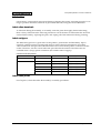
DIP switches
Serial interface model
Table 1-8 DIP switch 1
SW 1
Function
ON
OFF
1
Data reception error
Ignored
Prints “?”
2
Receive buffer capacity
45 bytes
4K bytes
3
Handshaking
XON/XOFF
DTR/DSR
4
Word length
7 bits
8 bits
5
Parity check
Yes
No
6
Parity selection
Even
Odd
7
Transmission speed selection
Refer to Table 1-9
8
Table 1-9 Transmission speed
Transmission Speed[BPS]
SW 1-7
SW 1-8
2400
ON
ON
4800
OFF
ON
9600
ON
OFF
19200
OFF
OFF
(BPS: Bits Per Second)
Table1-10 DIP switch 2
SW 2
Function
ON
OFF
1
Handshaking (BUSY condition)
Receive buffer full
Offline or
receive buffer full
2
Customer display (DM-D) connection
Connected
Not connected
3
Head rank switching
Rank B
Rank A
4
Power switch mode setting
Power switch fixing
mode
Normal mode
5
Interlocking operation with IM
Interlocking
Not interlocking
6
Internal use
—
Fixed to OFF
7
I/F pin 6 reset signal
Enabled
Disabled
8
I/F pin 25 reset signal
Enabled
Disabled
Note:
Rev. A
Changes in DIP switch settings (excluding switches 2-7 and 2-8, interface reset signals) are recognized only
when the printer power is turned on or when the printer is reset by using the interface. If the DIP switch
setting is changed after the printer power is turned on, the change does not take effect until the printer is
turned on again or is reset.
Specifications 1-7
Confidential
Parallel interface model
Table 1-11 DIP switch 1
SW 1
Function
ON
OFF
1
Automatic line feed
Always enabled
Always disabled
2
Receive buffer capacity
45 bytes
4K bytes
3
Undefined
—
—
4
Undefined
—
—
5
Undefined
—
—
6
Undefined
—
—
7
Undefined
—
—
8
Undefined
—
—
Table1-12 DIP switch 2
SW 2
Function
ON
OFF
1
Handshaking (BUSY condition)
Receive buffer full
Offline or
receive buffer full
2
Internal use (Do not change settings)
—
Fixed to OFF
3
Head rank switching
Rank B
Rank A
4
Power switch mode setting
Power switch fixing
mode
Normal mode
5
Interlocking operation with IM
Interlocking
Not interlocking
6
Internal use
—
Fixed to OFF
7
Internal use (for serial interface)
—
Fixed to OFF
8
I/F pin 31 reset signal
(Do not change settings)
Fixed to ON
—
Note:
Changes in DIP switch settings (excluding switches 2-7 and 2-8, interface reset signals) are recognized only
when the printer power is turned on or when the printer is reset by using the interface. If the DIP switch
setting is changed after the printer power is turned on, the change does not take effect until the printer is
turned on again or is reset.
1-8 Specifications
Rev. A
Confidential
TM-J8000/J8000P Technical Manual
Internal buffer
❏ Receive buffer:
Selectable as 45 or 4K bytes using the DIP switch
❏ User-defined buffer (both for user-defined characters and downloaded bit images):
Receipt: 12K bytes
Slip:
5K bytes
❏ Macro buffer:
2K bytes
Electrical characteristics
❏ Supply voltage:
AC85 V to 264.5 V (only for single phase)
Universal power supply is built in.
❏ Current consumption:
25 W (Operating)
Reliability
❏ Printer mechanism life (when printing alphanumeric characters):
Receipt section: 10,000,000 lines
Slip section:
5,000,000 lines
Printer is defined to have reached the end of its life when it
reaches the beginning of the wearout period.
❏ Print head life:
800 million dots/nozzle
❏ Autocutter life:
2,000,000 cuts
❏ MTBF:
180,000 hours
Failure is defined as Random Failure occuring during the time
of the Random Failure Period.
❏ MCBF:
37,000,000 lines
This is an average failure interval based on failures relating to
wearout and random failures up to the life of 12 million lines.
Dimensions/Weight
❏ Dimension:
325 × 200 × 300 mm (W × H × D)
(12.8 × 7.9 × 11.9 in.)
❏ Weight:
Approximately 9 kg
Rev. A
Specifications 1-9
Confidential
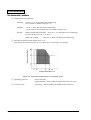
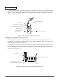
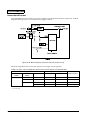
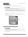
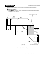
Environmental condition
❏ Temperature and Humidity:
Printing:
10 to 35 °C, 20 to 80% RH (non-condensing)
(Area which is shaded in Figure 1-1.)
Standby:
5 to 40 °C, 20 to 80% RH (non-condensing)
(Area which is surrounded with a solid line in Figure 1-1.)
Storage:
When packed (ink not filled): –20 to 60 °C, 5 to 85% RH (non-condensing)
(within 120 hours at –20 °C or 60 °C)
When ink is filled:
–20 to 40 °C, 20 to 85% RH (non-condensing)
❏ Absolute maximum rated temperature: 70 °C
(The printer must be kept below 70 °C whenever it is operating or in storage.)
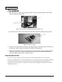
Figure 1-1 Operating temperature and humidity range
❏ Operating pressure:
700 to 1050 hPa
(approximately –20 m to 2000 m height above the sea level)
❏ Acoustic noise:
Operating: Approximately 49 dB (Bystander Position)
1-10 Specifications
Rev. A
Confidential
TM-J8000/J8000P Technical Manual
EMI and safety standards applied
The following standards are applied only to the printers that are so labeled.
Europe
CE marking
North America
EMI
FCC Class A
Safety standards
UL 1950-3rd
CSA C22.2 No.950
Japan
EMI
VCCI Class A
Oceania
EMC
AS/NZS 3548
Receipt Section
Paper feeding mechanism
❏ Paper feeding method
Friction feed method
❏ Minimum paper feeding pitch:
Possible to set 0.141 mm (1/180 inch) minimum
❏ Paper feeding speed:
35.3 ms/l, when the paper feeding pitch is set to 4.23 mm
(1/6 inch)
120 mm/s (approximately 4.7 inches/s, 28.3 l/s) when
continuous paper feeding is performed.
Paper roll specification
❏ Paper type:
Normal quality paper (possible to use only single-ply sheet)
❏ Form:
Paper roll
❏ Paper width:
76 ± 0.5 mm
❏ Paper thickness:
0.06 to 0.09 mm
❏ Paper weight:
52.3 to 64.0 g/m2 (JIS P8124)
❏ Spool diameter:
Inside:
❏ Paper roll diameter:
Outside: 83 mm or less
10 mm or more
Autocutter
❏ Cutting method:
Circular cut method
❏ Cutting type:
Cutting with no point left uncut (called “Full cut”)
Rev. A
Specifications 1-11
Confidential
Slip Section
Paper feeding mechanism
❏ Paper feeding method:
Friction feed method
❏ Minimum paper feeding pitch:
Possible to set 0.141 mm (1/180 inch) minimum
❏ Paper feeding speed:
35.3 ms/l, when the paper feeding pitch is set to 4.23 mm
(1/6 inch)
120 mm/s (approximately 4.7 inches/s, 28.3 l/s) when
continuous paper feeding is performed.
Slip paper (includes personal check)
❏ Paper type:
Normal quality paper (possible to use only single-ply sheet)
❏ Paper size:
Width: 68 to 215.9 mm
Length: 68 to 297.0 mm
❏ Paper thickness:
0.09 to 0.15 mm
❏ Weight:
64 to 110 kg/m2 (JIS P8124)
1-12 Specifications
Rev. A
TM-J8000/J8000P Technical Manual
Confidential
Chapter 2
Outline of Operation
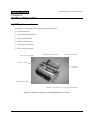
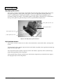
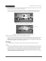
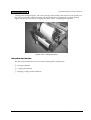
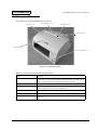
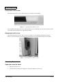
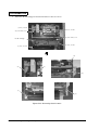
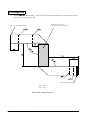
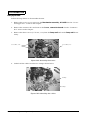
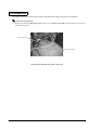
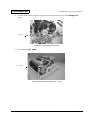
M-J8000 printer mechanism
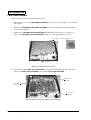
The printer is comprised of the following major mechanisms.
❏ Print mechanism
❏ Roll paper feed mechanism
❏ Slip feed mechanism
❏ Detector mechanisms
❏ Autocutter mechanism
❏ Ink system mechanism
ink system mechanism
roll paper feed mechanism
autocutter mechanism
print mechanism
ink system
mechanism
slip feed mechanism
(*) Detector mechanisms are not shown in this illustration.
Figure 2-1 External appearance of M-J8000 printer mechanism
Rev. A
Outline of Operation 2-1
Confidential
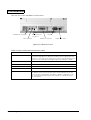
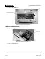
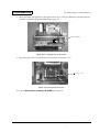
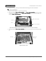
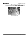
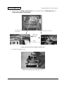
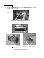
Print mechanism
This mechanism is comprised of the following: the print head unit (128-nozzle unit, with nozzles
arranged in two vertical columns with 64 nozzles each), the head carriage assembly, carriage
frame ("Frame, carriage"), the platen, the carriage motor assembly, the carriage-guide shaft
("Shaft, carriage guide"), the carriage belt ("Belt, carriage"), and the carriage transmit pulley
plate assembly.
platen
print head unit
head carriage assembly
belt, Carriage
shaft, carriage guide
carriage transmit
pulley plate
assembly
frame, carriage
carriage motor
assembly
Figure 2-2 Print mechanism
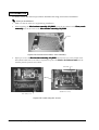
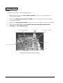
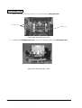
Movement of the print head unit
When the carriage motor ("Motor, carriage") rotates the carriage-drive pulley ("Pulley, carriage
drive") in the direction of the arrow A (see Fig. 2-3), the pulley drives the carriage belt ("Belt,
carriage"), together with the head carriage assembly (which is affixed to the carriage belt), in the
arrow A’ direction.
2-2 Outline of Operation
Rev. A
TM-J8000/J8000P Technical Manual
Confidential
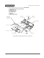
In the same way, rotation of the carriage motor in the arrow B direction causes the head carriage
assembly to move in the arrow B’ direction.
A’
B’
head carriage assembly
B
A
motor, carriage
pulley, carriage drive
Figure 2-3 Movement of the Print head unit
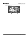
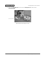
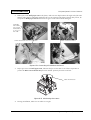
Printing
The ink-jet head consists of the following components: head chip that holds the 128 ink-jet
nozzles and the 128 electrostatic actuators (one actuator per nozzle), base head that supplies the
ink, head board containing the signal circuit, thermistor (mounted on head board; used to
monitor the temperature), left and right driver ICs (used to drive the head chip), and a cover
head that protects the head chip and driver ICs.
The head chip has128 nozzles; two rows (A and B) of 64 nozzles each. The nozzle arrangement is
shown in Figure 2-6. Each driver IC drives the nozzles of a single row.
The ink-jet head is connected to the Main board by an FPC through a connector.
The printing sequence is as follows:
1. The driver ICs apply electric pulses to the appropriate nozzles, where timing is according to
the phase changes of the carriage motor.
2. The electrostatic actuators are activated by the pulse, causing ink to eject from the nozzles.
3. The ink adheres to the paper, forming printed dots.
Rev. A
Outline of Operation 2-3
Confidential
4. A printed pixel (or segment) consists of two dots. To print a segment, two consecutive pulses
are applied to the relevant nozzle (to print to consecutive dots).
base head
head-rank
setting
(short land)
gap-rank indication
circuit board
thermistor
Figure 2-4 Head (top view)
head Chip
cover head
base head
driver head IC
(under cover head)
Figure 2-5 Head (bottom view)
Figure 2-6 Nozzle arrangement
2-4 Outline of Operation
Rev. A
Confidential
TM-J8000/J8000P Technical Manual
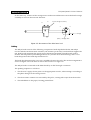
Data Input and Printing
Figure 2-7 shows a block diagram of the driver IC. Each driver IC receives input through its DI
(data) and XSCL.(sync) lines. These inputs are implemented separately on each of the two driver
ICs (so that each receives data independently).
The serial print data enters through the DI and moves into the SHIFT REGISTER in sync with
the XSCL signal. The data then moves into the LATCH in accordance with the LP timing signal.
The latched data passes through the inverter and sets the appropriate bits of the segment
driving, causing the nozzles to operate.
To control actual printing, the driver IC feeds the V3 terminal voltage waveform selectively to
the COM and SEG outputs. (See Fig. 2-8.) Ink ejection is generated when there is a difference
between the COM and SEG output voltages. To print a segment, the IC produces a positive
difference for the first pulse followed by a negative difference for the second pulse. To withhold
a segment, the IC maintains a zero difference.
The level and width of the applied pulse is adjusted according to the head rank (specific to each
head), the gap rank, and the temperature as detected by the thermistor. On the Main circuit
board, the head rank read information indicated by short-land setting. The gap rank sets DIP
switch on the Main circuit board to match the gap-rank marking on the head board.
Figure 2-7 Block diagram of driver IC
Rev. A
Outline of Operation 2-5
Confidential
Figure 2-8 Head drive implementation
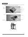
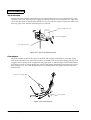
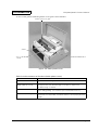
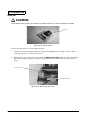
Roll paper feed mechanism
This mechanism comprises the paper-feed motor assembly, the power transmission mechanism,
the roll paper cover unit, the roll paper guide unit, and the detector mechanisms. For
explanations about the detector mechanisms (which includes the roll paper detection
mechanism, the roll paper near-end detection mechanism, and the cover-open detection
mechanism), see “Detector mechanism” in this chapter. The paper-feed operation is performed
by driving the paper-feed motor.
roll paper cover
unit
roll paper guide
unit
paper-feed motor
assembly
power transmission
mechanism
Figure 2-9 Roll paper feed mechanism
2-6 Outline of Operation
Rev. A
TM-J8000/J8000P Technical Manual
Confidential
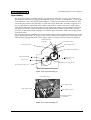
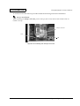
Paper feeding
The paper-feed motor assembly consists of a step motor and a gear ("Gear, paper feed motor").
The rotation of the motor propagates through three gears ("Gear, J/C changeover", "Gear, paper
feed reduction", and "Gear, paper feed transmit") on the power-transmission mechanism, and
causes the paper-feed roller assembly to rotate. The paper-feed roller assembly comprises two
main components: a paper-feed roller ("Roller, paper feed"), which consists of a wide rubber
roller and a shaft, and a paper-feed gear ("Gear, paper feed") that is pressure-fitted to the shaft.
The paper-feed roller is pressed against the paper-hold roller ("Roller, paper hold") at fixed
pressure, so that the inserted roll paper is secured in place and can be fed by the turning action
of the feed roller.
The roll paper tension mechanism is a friction-clutch device that maintains a fixed tension on the
paper. When paper-feed is in progress, this tension stretches the paper between the paper-feed
roller and the paper-guide plate ("Plate, paper guide") creating a smooth surface for printing.
pape feed roller
assembly
roller, paper feed
roller, paper hold
gear, paper feed
gear, paper feed transmit
roller, paper-feed
gear, paper feed
reduction
step motor
gear, J/S changeover
gear, paper feed motor
Figure 2-10 Paper feeding (1)
roller, paper hold
roller, paper feed
gear, paper feed
roller, paper tension
roll paper tension
mechanism
gear, paper feed transmit
Figure 2-11 Paper feeding (2)
Rev. A
Outline of Operation 2-7
Confidential
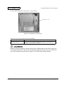
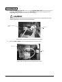
Paper loading
The paper roll is loaded by putting it into the roll paper guide unit (which includes the paper
supply section). The roll paper guide unit can be accessed by lifting the lock lever ("Lever, CS
lock") and opening the cover ("Roll paper cover unit"). The operator puts the paper roll into
place, pull out a small amount of the paper, and closes the cover. This causes the paper to set
into the path illustrated in the figure below. When the cover is closed, the paper-feed gear
("Gear, paper feed") engages the paper-feed-transmission gear ("Gear, paper feed transmit"),
enabling the paper to be fed. Though a small paper slackness between the paper guide roller and
paper-guide plate will occur right after installing the paper, a fixed-length feed function (linked
to the cover-open detection signal) will eliminate the paper slackness. This mechanism allows
for easy loading of paper rolls and easy clearing of paper jams.
lever, CS lock
paper roll
roll paper cover unit
roll paper guide unit
Figure 2-12 Paper loading (1
)
paper
roller, paper hold
roller, paper feed
print surface
roller, paper tension
Figure 2-13 Paper loading (2)
2-8 Outline of Operation
Rev. A
TM-J8000/J8000P Technical Manual
Confidential
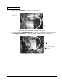
J/S changeover mechanism
This printer uses a single motor to feed both roll paper and slips. The J/S changeover
mechanism switches the gear train so as to drive the correct paper. The mechanism consists of a
gear ("Gear, J/S changeover"), solenoid ("Solenoid, J/S changeover"), and lever ("Lever, J/S
changeover"). Energizing the solenoid causes the lever to slide the gear so that it engages the
paper-feed reduction gear ("Gear, paper-feed reduct") on the roll paper side, completing the gear
train for roll paper feed. De-energizing the solenoid causes the lever to spring back (pulled by
the Spring, J/S changeover), so that the gear slides to the other side and engages the slip feed
reduction gear ("Gear, slip-feed reduction") on the slip side, completing the gear train for slip
feed.
gear, slip feed reduction
(roll paper side)
gear, paper feed reduction
(slip side)
gear, J/S changeover
motor, paper feed
lever, J/S changeover
spring, J/S changeover
solenoid, J/S changeover
Figure 2-14 J/S changeover mechanism
Slip feed mechanism
This mechanism consists of a slip paper guide section and a slip feed roller section. The guide
section guides the paper to the print position. The roller section is comprised of three sets of
rollers that transport the slip.
Rev. A
Outline of Operation 2-9
Confidential
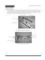
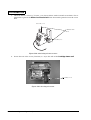
Slip paper-guide section
This section consists of four major components: the front slip guide ("Paper guide, slip, front"),
the upper slip guide ("Paper guide, slip, upper"), the lower slip guide ("Paper guide, slip,
lower"), and the platen ("Paper guide, platen"). The paper path accepts slip paper up to a
maximum width of 215.9mm. A slip holder guide ("Paper guide, slip hold, top") is attached at
the top of the platen to guide the slip as it moves upward from the print area.
paper guide, slip hold, top
paper guide, platen
paper guide, slip, front
paper guide, slip, lower
Figure 2-15 Slip paper guide Section
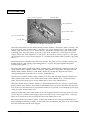
Slip Feed Roller Section
This section consists of three sets of rollers: front-feed rollers, center-feed rollers, and top-feed
rollers.
The front-feed rollers ("Roller, slip feed, front" and "Roller, slip hold, front") pull the inserted slip
paper into the paper path.
The center-feed rollers ("Roller, slip feed, center" and "Roller, slip hold, center") feed the slip
paper during printing on the slip paper.
The top-feed rollers ("Roller, slip feed, top" and "Roller, slip hold, top") feed the lower edge of
the slip paper eject it from the printer.
2-10 Outline of Operation
Rev. A
TM-J8000/J8000P Technical Manual
Confidential
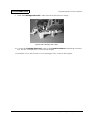
When the J/S changeover mechanism is switched to the slip-feed mechanism side, the drive
power from the paper feed motor ("Motor, paper feed") drives each gear on the drive side; all
three of the slip-feed rollers rotate simultaneously.
gear, slip feed reduction
gear, slip feed
roller, slip hold, top
gear, slip feed transmit 1
roller, slip feed, top
roller, slip hold, center
gear, slip feed
roller, slip feed, center
gear, slip feed transmit 2
motor, paper feed
gear, J/S changeover
gear, slip feed
roller, slip feed, front
roller, slip hold, front
Figure 2-16 Slip feed roller Section
Front-feed rollers
The driven rollers ("Roller, slip hold, front") are opened and closed by a shutter mechanism to
which they are linked.
Center-feed rollers
The surface of the rollers that make contact with the paper have been blast-coated with metal
powder. The three driver rollers ("roller, slip hold, center") are supported on the groove of the
shutter frame ("Frame, shutter") by the shaft ("Shaft, slip hold, center"). The paper is held by the
force of the spring ("Spring, slip hold, center) through the lever ("Lever, sleeve hold, center").
Rev. A
Outline of Operation 2-11
Confidential
Top-feed rollers
The driven rollers ("Roller, slip hold, top") are supported by lever ("Lever, slip hold, top"). The
solenoid ("Solenoid, slip hold, top") engaged at the tip of the lever causes the lever to open and
close. The operation to absorb the solenoid’s iron core causes the rollers to open. The rollers will
then stay open even after the solenoid power is shut off.
Solenoid, Slip Hold, Top
Solenoid energized
Lever, Slip Hold, Top
Figure 2-17 Top Feed-Roller Section
Form stopper
The form stopper positions the slip as it inserted. The stopper is attached to a fulcrum on the
base frame ("Frame, base").When the printer is in standby, the force of the spring ("Spring, form
stopper") forces the tip of the stopper into the paper path, so that the paper cannot enter. When
the printer is ready to start printing, the action of the shutter mechanism cause the lever ("lever,
form stopper O/C") to rotate in the direction A1, pushing the form stopper downward in the
direction A2.
Lever, form stopper O/C
A1
A2
Form Stopper
Figure 2-18 Form Stopper
2-12 Outline of Operation
Rev. A
TM-J8000/J8000P Technical Manual
Confidential
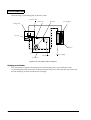
Shutter mechanism
Operating principle
The purpose of this mechanism is to hold the entering slip firmly against the platen at the open
area of the Platen where carriage passes through, so that the sheet is correctly guided up to the
top slip-holder paper guide ("Paper guide, slip hold, top"). The shutter mechanism also controls
the open/close action of the front-feed rollers and the form stopper.
shaft, shutter guide
holding plate, slip
frame, shutter
cam, shutter drive
Figure 2-19 Shutter mechanism (1)
)
shutter, slip
shaft, shutter, R
shaft, shutter, R
roller, slip hold, front
Figure 2-20 Shutter mechanism (2)
Rev. A
Outline of Operation 2-13
Confidential
lever, form stopper O/C
lever, slip O/C
lever, shutter drive
gear, shutter reduct
cam, form stopper O/C
motor, shutter
cam, slip O/C
Figure 2-21 Shutter mechanism (3)
The main components are: the shutter frame ("Frame, shutter"), the motor ("Motor, shutter"), the
reduction gear ("Gear, shutter reduct"), the drive cam ("Cam, shutter drive"), the slider ("Slider
shutter"), the drive lever ("Lever, shutter drive"), the shutter ("Shutter, slip"), the holder plate
("Holding plate, slip"), the open/close cam ("Cam, form stopper O/C"), the open/close form
stopper cam (Cam, form stopper O/C), the open/close slip lever ("Lever, slip O/C"), the open/
close stopper lever ("Lever, form stopper O/C"), and the front holder rollers (“Rollers, slip, hold,
front”).
The holder plate is installed at the end of the shutter. The plate uses two springs ("Spring, slip
holding plate, R" and "Spring, slip holding plate, L") to press the paper against the platen
("Platen, paper guide").
The end of the shutter guide shaft ("Shaft, shutter guide," attached to the shutter) fits into a slit
on the shutter frame ("Frame, shutter") and can slide parallel to the platen. The right and left
shutter shafts ("Shaft, shutter, L" and "Shaft, shutter, R") fit into the diagonal slits on the
corresponding ends of the drive lever ("Lever, shutter drive").
The drive lever and the slider ("Slider, shutter") can move left and right along the shutter lever
shaft ("Shaft, shutter lever"). The shutter drive shaft ("Shaft, shutter drive"), mounted on the
slider, fits into the spiral groove on the shutter drive cam ("Cam, shutter drive").
When the shutter motor ("Motor, shutter") is turned in the direction A1 (see Fig. 2-22) from the
home position of the shutter, the rotation of the shutter drive cam causes the slider and the drive
lever to move in the direction A2. The shutter itself moves upward, as it is lifted along the slope
of the slit on the shutter-drive lever.
The gear on the other side of the shutter drive cam engages and drives the slip open/close cam
("Cam, slip O/C") and the form stopper open/close cam ("Cam, form stopper O/C"). The slip
open/close cam turns at one second of the rate of the shutter drive cam.
Because the three cams rotate in phase, rotating the shutter motor some specified number of
turns (starting from home position) can select the sutter mechanism, the open/close state of both
the front feed roller and the form stopper.
2-14 Outline of Operation
Rev. A
TM-J8000/J8000P Technical Manual
Confidential
The shutter detection mechanism can be used to detect abnormal shutter operation and to adjust
the home position at time of shutter initialization.
The user can control the shutter mechanism manually by turning the shutter reduction gear
("Gear, shutter reduction") at the point where it projects outward from the carriage frame.
A2
A1
Figure 2-22 Shutter mechanism home position
shutter, slip
Figure 2-23 Shutter mechanism paper-insertion position
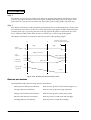
Shutter-mechanism timing chart, and slip insertion operation
Figure 2-24 shows the timing chart. Operation begins by initializing the shutter mechanism, and
placing it in standby state at home position. The mechanism is in lowered position, the front
slip-holder rollers ("Roller, slip hold, front") are open, and the form stopper is blocking the paper
path (so that it is possible to set the slip into position).
Slip insertion
To insert the paper, the shutter mechanism and slip feed mechanism operate as follows:
Step 1
When a slip is inserted, the T.O.F. and B.O.F detectors both detect the insertion of the slip. This
causes the shutter motor ("Motor, shutter") to rotate in the CW direction and stops at the phase
point indicated as T1 in the timing chart. At this point, the front slip-holder rollers are closed
and the form stopper is no longer blocking the paper path. The paper feed motor now starts
rotating, and loading the sheet. When the edge of the slip passes center slip feed rollers ("Roller,
slip feed, center"), the paper-feed motor stops.
Rev. A
Outline of Operation 2-15
Confidential
Step 2
The shutter motor now turns in the CCW direction, returning the shutter mechanism to home
position. The paper-feed motor then starts again, feeding the leading edge of the paper to the
point where it is just about to reach the top slip holder guide ("Paper guide, slip hold, top").
Step 3
The shutter mechanism reaches the phase point indicated as T2 in the timing chart. At this point
the shutter has risen almost to the level of the slip holder paper guide, and the slip holder plate
("Holder plate, slip") is pressing the end of the slip against the platen so that it does not come
loose. Further feeding of the sheet advances it all the way to the top slip holder guide.
The shutter mechanism is returned to the home position; then printing begins.
T2
Low
T1
Low
High
shutter home position
motor, shutter CW rotation
Low
High
shutter
sensor signal
Paper path open
form
stopper
Paper path close
Roller open
roller, slip
hold, front
Roller open
Roller close
Up
shutter, slip
operation
Down
Figure 2-24 Shutter mechanism timing chart
Detector mechanisms
The M-J8000 includes the following detector mechanisms.
Home-position detector mechanism
Detects home position of the head carriage ass’y.
Carriage detector mechanism
Detects errors in head-carriage operation.
Pump position detector mechanism
Detects home position of the pump roller.
Ink-near-end detector mechanism
Detects presence of ink in the ink cartridge.
Cartridge detector mechanism
Detects presence of the ink cartridge.
2-16 Outline of Operation
Rev. A
TM-J8000/J8000P Technical Manual
Confidential
T.O.F. detector mechanism
Detects presence of a slip.
Paper-width detector mechanism
Detects presence of a slip.
B.O.F. detector mechanism
Detects presence of a slip.
Slip detector mechanism
Detects presence of a slip.
Shutter detector mechanism
Detects home position of shutter.
Roll paper detector mechanism
Detects presence of roll paper.
Roll paper near-end detector mechanism
Detects presence of roll paper.
Cover-open detector mechanism
Detect state of the roll paper cover.
Cutter detector mechanisms
Detects home positioning of the cutter mechanism.
Home-position detector mechanism
This mechanism is installed at the right end of the head carriage assembly stroke range. The
mechanism detects the carriage assembly’s position as well as errors in the carriage operation.
The detector detects the detection plate located on the rear of the carriage assembly as default.
The detector consists of an LED and a photo IC. When the carriage assembly moves, the detector
plate pass through between the LED and the photo IC. Since the optical axis is blocked at this
time, the level of the IC output will be changed. The change in IC output serves as the detection
signal of the moving position of the carriage assembly.
Figure 2-25 Home position detector
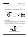
Carriage detector mechanism
This mechanisms uses a rotary encoder mounted directly on the rotating shaft of the carriage
motor ("Motor, carriage") to detect errors in motor rotation. The mechanism consists of a
detector plate ("Detector plate, carriage") and a carriage detector.
Rev. A
Outline of Operation 2-17
Confidential
The carriage detector consists of an LED and a photo IC. The circular detection plate, which
looks like a wagon wheel, has 12 evenly spaced plate which blocks the light along the
circumference of the detection plate, and there are open spaces in between. The detector plate is
mounted directly on the rotating shaft of the carriage motor. Rotation of the carriage motor
therefore causes the plate to turn as well. The turning of the plate alternately blocks and opens
the passage of light from the LED to the photo IC, causing changes in the output level from the
IC. Detection is made by monitoring the changes in the output level.
carraige detector
detection plate,
carriage
motor, cariiage
Figure 2-26 Carriage detector mechanism
2-18 Outline of Operation
Rev. A
TM-J8000/J8000P Technical Manual
Confidential
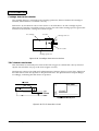
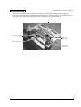
Pump position detector mechanism
This mechanism detects the roller position. The mechanism consists of a pump-position detector
plate (linked to a pressure pulley) and a pump-position detector.
The pump-position detector consists of an LED and a photo IC. The detector plate, which
includes a cutout area, fits between the LED and the photo IC and is turned by the power of the
pump motor.
When the cutout area moves into this area it allows light to pass from the LED to the IC, causing
a change in the IC output which services to detect the roller position
.
pump position
detector
pressure
pulley
roller
pump position
detector plate
Figure 2-27 Pump position detector mechanism
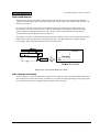
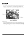
Ink nearend detector mechanism
The ink nearend detector is mounted on the cartridge guide unit, and monitors the ink level in
the installed ink cartridge.
Detection is by mechanical contact. The contact remains open so long as the cartridge contains a
sufficient level of ink. When the ink level runs low, the detector plate mounted on the cartridge
presses on the detector’s actuator, causing the contact to close.
When the detector detects that ink has run out, it resets the ink usage counter. Ink-end will occur
when ink usage reaches the specified value
.
ink cartridge
ink pack
acutuator
ink nearend detector plate
ink discharging absorber
ink nearend detector
cartridge guide unit
Figure 2-28 Ink nearend detector mechanism
Rev. A
Outline of Operation 2-19
Confidential
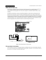
Cartridge detector mechanism
The cartridge detector, mounted on the cartridge guide unit, detects whether the cartridge is
installed, and whether it is installed correctly.
Detection is by mechanical contact. The contact is closed if there is no ink cartridge in place.
When the ink cartridge is installed correctly in place, the side of the cartridge presses against the
actuator on the detector, causing the contact to open.
ink cartridge
actuator
cartridge detector
ink needle
cartridge guide unit
Figure 2-29 Cartridge detector mechanism
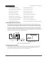
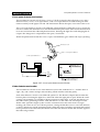
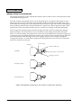
T.O.F. detector mechanism
This mechanism is mounted just in front of the form stopper to confirm that a newly inserted
slip has moved all the way up to the form stopper correctly.
The detector consists of an LED and a phototransistor. When a slip moves into place, light from
the LED reflects from the slip back to the phototransistor. The phototransistor output changes
accordingly, indicating that the sheet is in position.
Figure 2-30 T.O.F. detection circuit
2-20 Outline of Operation
Rev. A
TM-J8000/J8000P Technical Manual
Confidential
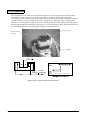
Paper-width detector
This detector detects the width of the inserted slip. The detector is mounted approximately
122mm from the right edge of the paper path. If the slip is wider than 122mm, the detector will
detect its presence.
In most cases checks are narrower than 122mm when fed vertically, but wider when fed
horizontally. In cases where the user wishes to feed checks horizontally, the detector helps
protect against accidental insertion of such checks in the vertical direction: if the check is
inserted vertically, the detector will not detect it.
The detector consists of an LED and a phototransistor. When a slip moves over the detector area,
LED reflects from the slip back to the phototransistor. The phototransistor output changes
accordingly, indicating that the sheet exists at that position.
Figure 2-31 Paper-width detector circuit
B.O.F. detector mechanism
This mechanism is used to determine slip presence (when the slip is inserted) and the bottom of
the form (bottom end of the sheet). The detector is located near the right edge of the paper path,
to confirm that the sheet is aligned with the right side of the path.
Rev. A
Outline of Operation 2-21
Confidential
The detector consists of an LED and a phototransistor. When a slip moves into place, light from
the LED reflects from the slip back to the phototransistor. The phototransistor output changes
accordingly, indicating that the sheet is in position.
Figure 2-32 B.O.F. detection circuit
Slip detector mechanism
This mechanism is located just before the print position to confirm that the slip has advanced to
the print position. By ensuring that the slip has reached the print area correctly, the mechanism
helps prevent printing without a slip paper.
The detector mechanism consists of a slip detection lever ("Lever, slip detection"), an LED, and a
photo IC. When the sheet moves into position, it pushes the lever in direction A (see Figure). The
other end of the lever moves between the LED and the photo IC, blocking the light flow. This
changes the IC output level, indicating that paper is present.
slip
holding plate, slip
paper guide, platen
lever, slip detect
(Paper is detected.)
lever, slip detect
(No paper [standing by])
shutter, slip
slip detector
slip detector
Figure 2-33 Slip detector mechanism
2-22 Outline of Operation
Rev. A
TM-J8000/J8000P Technical Manual
Confidential
Shutter detector mechanism
This detector confirms that the shutter moves into home position (at initialization) and detects
errors during the shutter operation. The detector mechanism is mounted around the
circumference of the slip open/close cam ("Cam, slip O/C") inside the shutter frame ("Frame,
shutter").
The detector mechanism consists of an LED and a photo IC, and works in conjunction with
blocker areas on the cam. As the cam turns, the blocker areas moves in and out of the space
between the LED and the photo IC, alternately blocking and opening the light path and thereby
changing the IC output level. Operation is based on the fact that the cam moves in sync with the
shutter mechanism. There are only three phase positions (including home position) at which the
shutter mechanism stops. The blocker forms are fitted so that they move into the detector (and
block the light path) only when the shutter is located at the phase position.
cam, slip O/C
cam, shutter drive
shutter detector
Figure 2-34 Shutter detector mechanism
Roll paper detector mechanism
This mechanism consists of a roll paper detector combined with a microswitch and a detection
lever, and is mounted on the roll paper guide ("Paper guide, roll paper"). The mechanism detects
the presence of roll paper within the paper path.
Rev. A
Outline of Operation 2-23
Confidential
A spring within the microswitch holds the lever so that it juts out into the paper path. When roll
paper moves along the path, it presses the lever back out of the path, causing the microswitch
contact to open. When paper runs out, the spring pulls the lever back into position, closing the
contact on the microswitch.
roll paper
plate, paper guide
lever position (no paper)
lever position (paper is present)
detection lever
roll paper detector
(micro switch)
paper guide, roll paper
Figure 2-35 Roll paper detector mechanism
Roll paper nearend detector mechanism
This mechanism consists of a nearend detector lever and a microswitch. The mechanism is
mounted on the side of the roll paper guide ("Paper guide, roll paper"), and serves to detect the
amount of paper remaining on the roll.
A spring inside of the microswitch presses the lever against the side of the paper roll. As long as
there is sufficient paper on the roll, the lever keeps the microswitch contact closed. As paper
runs out, the edge of the lever moves into the paper core. In this state, the microswitch contact is
open and detects paper-out.
microswitch
paper guide, roll paper
nearend detector lever
(nearend detection position)
roll paper
Figure 2-36 Roll paper nearend detector mechanism
2-24 Outline of Operation
Rev. A
TM-J8000/J8000P Technical Manual
Confidential
Cover-open detector mechanism
This mechanism consists of lock lever ("Lever, CS lock") located on the roll paper cover, and a
detection lever ("Lever, cover-open detect") and cover-open detector located on the gear-train
frame assembly on the paper roll side. The mechanism detects the open/close state of the cover.
The cover-open detector consists of an LED and a phototransistor. When the cover is closed, the
lock lever rotates the detection lever such that the blocker plate on the other end of the detection
lever moves between the LED and phototransistor, blocking the light flow and changing the IC
output. The change in IC output detects the open/closed state.
When the printer detects that the cover is open, it immediately goes offline and stops operating.
lever, CS lock
lever, cover-open detect
cover-open detector
Figure 2-37 Cover-open detector mechanism
Cutter detector mechanism
This mechanism consists of two cutter detectors (one at left, indicated as "L", and the other at
right, "R"), and a cutter carriage sub-assembly (which includes a blocker plate).
Each cutter detector consists of an LED and a photo IC. The detector outputs HIGH when the
blocker plate is blocking the light flow, and LOW when the light path is open. When the cutter
carriage sub-assembly is in standby at home position on either the L or R side, the detector on
that side will be generating a HIGH, while the detector on the other side will output a LOW.
When cutter operation begins (when a cutter command causes the cutter motor to begin
turning), the cutter moves out of home position, causing the blocker to move out of the detector,
so that L/R detectors will be outputting LOW. When the cutter completes operation and reaches
home position on the other side, the blocker will enter the detector at that side and the signal at
that side will go HIGH.
Rev. A
Outline of Operation 2-25
Confidential
The printer uses these signals to control stopping of the cutter motor and to detect errors related
to the cutter mechanism.
blocker plate
cutter detector
cutter carriage sub-assembly
Figure 2-38 Cutter detector mechanism
Autocutter mechanism
The autocutter mechanism consists of a transmission mechanism, a detection mechanism, and a
cutter mechanism. For information about the detection mechanism, refer to "Cutter detection
mechanism" in this chapter.
Transmission mechanism
This mechanisms consists of the following components: cutter-motor gear ("Gear, motor AC")
mounted on the shaft of the cutter motor ("Motor, AC"); reduction gear ("Gear, reduction AC "),
transmission gear ("Gear, transmission AC"), a pair of pulleys ("Pulleys, belt drive AC"), a belt
("Belt, carriage AC"); and the carriage drive shaft ("Shaft, carriage drive"), which is fixed to the
belt.
2-26 Outline of Operation
Rev. A
TM-J8000/J8000P Technical Manual
Confidential
The rotation speed from the cutter motor passes from the cutter-motor gear through the
reduction and transmit gears (which reduce the speed) to the drive pulley. The rotation power of
the gears move the pulley and the belt; then it moves the carriage drive shaft.
motor, AC
gear, motor AC
gear, reduction AC
shaft, carriage drive
gear, AC
transmission
belt, carriage AC
pulley, belt
drive AC
Figure 2-39 Autocutter transmittion mechanism
Rev. A
Outline of Operation 2-27
Confidential
Cutter mechanism
This mechanism is comprised of a cutter carriage sub-assembly, the circular cutting blade subassembly, a holding spring ("Spring, CCB hold"), three gears ("Gear, CCB driving," "Gear, CCB
transmission,” and "Gear, AC rack"), and a fixed blade (Linear cutting blade). The circular
cutting blade sub-assembly, which is mounted in the cutter carriage sub-assembly, is pressed
against the fixed blade by the force of the holding spring.
gear, CCB transmission
gear, rack AC
gear, CCB driving
spring, CCB hold
carriage cutter
sub-assembly
linear cutting blade
circular cutting blade sub-assembly
Figure 2-40 Cutter mechanism
Cutting operation
When the cutter carriage sub-assembly starts from home position at either the right (R) or left (L)
side, the motor is activated so that it rotates in the direction of the arrow (see illustration); the
rotation force passes into the transmission mechanism, causing the cutter carriage sub-assembly
which is engaged the carriage drive shaft to move in the direction of the arrow. The resulting
rotation of the gear, AC rack and the gear, CCB transmission causes the gear, CCB driving to
turn, so that the circular cutting blade sub-assembly also turns in the direction of the arrow,
2-28 Outline of Operation
Rev. A
TM-J8000/J8000P Technical Manual
Confidential
catching and cutting the paper. The cutter carriage sub-assembly then reaches home position on
the side opposite from which it started, causing the detection mechanism to output a HIGH
signal. The system responds by stopping the cutter motor, completing the sequence.
Figure 2-41 Cutting operation
Ink system mechanism
The ink system mechanism consists of the following three mechanisms.
❏ Pump mechanism
❏ Capping mechanism
❏ Wiping/carriage-lock mechanism
Rev. A
Outline of Operation 2-29
Confidential
The following is a block diagram of the ink system.
cleaner head
clutch unit
flat gear
ink cartridge
carriage unit
cap unit
ink pack
pump motor
ink discharging
pump unit
Figure 2-42 Ink system block diagram
Pumping mechanism
This mechanism comprises the pump motor and the pump unit. The mechanism sucks
accumulating ink from the nozzles in the print head, and passes it through the cap section into
the ink discharge absorber inside the ink cartridge.
2-30 Outline of Operation
Rev. A
TM-J8000/J8000P Technical Manual
Confidential
The pump consists of a roller, a tube, and a pressure pulley (see illustration below). To collect
ink, the motor turns the pulley, causing the roller to press against and move around the tube.
This action changes the internal capacity of the tube, creating a vacuum force pressure that sucks
in the ink and ejects it into the ink cartridge.
roller
ink ejection
pressure pulley
ink absorption
<pump motor reverse rotation>
(Ink is not absorbed.)
<pump mortor forward rotation>
(Ink is absorbed.)
Figure 2-43 Pump mechanism
Capping mechanism
This mechanism prevents ink from drying and accumulating in the nozzle area during periods
when the printer is off or not printing. Exposure of the head nozzle to the air would tend to
cause the surface ink to stick because of drying. This capping mechanism covers the print head
with a cap holder to protect it from exposure.
The capping operation starts with the carriage unit in standby position, on the left of the head;
then the carriage unit moves to the right, toward its home position. As it approaches home
position, it engages the cap holder and moves it such that it covers the print head. The action
ends with the carriage unit in the home position and the cap holder covering the print head.
The front power switch (on the front panel) is installed on the secondary side of the printer’s
power circuit, so that power continues to exist for a certain interval after the front power switch
is set to off. If the user turns the power off while the head is uncapped, the capping mechanism
can complete capping in the interval before the power goes out.
carriage unit
print head
cap holder
air tube
to the ink discharging absorber
Figure 2-44 Capping mechanism
Rev. A
Outline of Operation 2-31
Confidential
Wiping/carriage-lock mechanism
The wiping mechanism wipes ink and dust off the surface of the nozzles, and is therefore a part
of the head-cleaning process.
Forward rotation of the pump motor acts on the pump gear, causing the clutch plate to move.
The motion of the clutch causes the cleaner head to advance into the motion path of the print
head. When the carriage unit carries the print head to the left or right, the nozzles brush against
the protruding cleaner head so that ink and dirt are wiped away. Reversing the rotation of the
pump motor causes the cleaner head to retract, so that it is no longer in the print-head path.
The carriage-lock mechanism prevents the carriage unit and cap from coming loose during
printer transport. The mechanism is also an extension of the wiping mechanism described
above. To execute locking, the pump motor runs in the forward direction while the carriage unit
is stationary at home position; this motor rotation moves the lock lever (though the movement of
the cleaner head) so that the edge of the lever engages the pin on the carriage, locking the
carriage unit in place. To unlock the carriage unit, the pump motor runs in reverse so that the
lock lever comes free of the pin.
carriage
cleaner head
cleaner head lever
<printing>
pump gear / clutch plate
carriage lock lever
<carriage locking.>
<carriage wiping>
Figure 2-45 Wiping/carriage-lock mechanism (cross section drawing)
2-32 Outline of Operation
Rev. A
TM-J8000/J8000P Technical Manual
Confidential
Overview of electrical circuit
The following is a block diagram of the TM-J8000 electrical circuit.
Figure 2-46 Block diagram of electrical circuit
Rev. A
Outline of Operation 2-33
Confidential
Main-board Unit
The main-board unit carries out the major part of TM-J8000 control. The unit includes the CPU/
memory control circuit, the mechanism drive circuit, the detection circuit, and the power control
circuit.
Gate array
Gate array
RTC
D-RAM
Program
ROM
CGROM
CPU
NV memory
Figure 2-47 Location of principal elements on the Main circuit board unit
2-34 Outline of Operation
Rev. A
TM-J8000/J8000P Technical Manual
Confidential
The following table describes the function of each of the principal elements on the main board
unit.
Table2-1 Major components and functions
Block
CPU
peripheral
area
Powerrelated
Rev. A
Location
Signals on
diagram
Description
Main Operation
U1
–
–
CPU, I/O port
U2
–
Custom gate array
I/O port (dip-switch, RTC, mechanism control,
etc.)
U3
–
Custom gate array
I/O port (CPU clock supply, SIO, mechanism
control, etc.)
U4
–
8Mbit (512K * 16
bits)
Program memory
U5
–
16Mbit (2048K * 8
bits)
Font memory
U15
–
256Kbit (32K * 8 bits;
serial I/O)
NV memory
U6
–
16Mbit (1024K * 16
bits)
D-RAM
U7
RTC
–
RTC
X1
–
32.788KHz
RTC clock
X2
–
14MHz
System clock (for U3)
X3
–
10MHz
System clock (for U3)
X4
–
1MHz
System clock (for U2)
U11
nRESET
–
System reset
U2I
–
–
Host-interface reset control
F1
154002
2A
Fuse for mechanism power
F1H
–
–
PTC thermistor, for inkjet-head power
U2
DM24V
DC24V, 400mA
For customer-display power
U8
IF24V
DC24V, 100mA
Power for UIB (Universal Interface Board)
U10
+24V
DC24V, 0.25A
Power for autocutter
Q4
+35V
DC35V, 1.2A
Semiconductor switch for mechanism power
supply
Q1
VCC
DC5V, 0.7A
Power semiconductor switch for control circuit
Q11
VHDIN
DC37V, 0.02A
Power semiconductor switch for ink jet head
U2M
–
DC15V, 0.01A
Not used
U1K
DKP
DC24V, 1A
Power for drawer
U5S
–
DC6V, 0.1A
Power for power-switch (front of printer)control
circuit
U6S
PC5V
DC5V, 0.1A
Power for power-switch (front of printer)control
circuit
U7S
–
–
Power (VCC) time-limit energizing timer for control
circuit
Outline of Operation 2-35
Confidential
Block
Connectors
Location
Signals on
diagram
Description
Main Operation
CN1
IM
–
IM-system power connector (power interlock
detect)
CN2
DKD
–
Drawer connector
CN3
I/F BOARD
–
UIB (Universal Interface Board) connector
CN4
DM
–
Customer display connector
CN5
–
–
Not used
CN10
PS
–
Power-unit connector
CN11
PSW
–
Power-switch connector (front of printer)
CN12
PANEL
–
Panel circuit board connector
CN20
–
–
Mechanism connector
CN21
–
–
Mechanism connector
CN22
IJ CON.
–
Ink jet head connector
CN30
FAN
–
Fan connector
U1
–
–
RS-232C conversion IC (for customer display)
QM1K
DKD1,
DKD2
DC24V, 1A
Drive transistor and output signal for, drawer
Not used
U1M
MIRD
Standard: 2.5V,
2.2P-P
Not used
Mechanismrelated
driver
U1A
ACM+,
ACM-
DC24V, 0.25A
Push-pull driver and output signal, for cutter motor
U1C
MT_A,
MT_B,
MT_C,
MT_D
DC35V, 0.7A
PWM-current-control-type unipolar steping motor
driver and output signal, for carriage drive
U1G
SLIP_PL-,
SLIP_PL-,
MICR_PL+,
MICR_PL-
DC35V, 1.17A/
0.39A
Push-pull driver and output signal, for slip-holder
solenoid
U1J
JS_PL+,
JS_PL-
DC35V, 0.85A/
0.175A
Push-pull driver and output signal, for journal/slip
switching solenoid
U1P
PF_A+,
PF_A-,
PF_B+,
PF_B-
DC35V, 0.6A
PWM-current-control-type bipolar steping motor
driver and output signal, for paper feed
U1U
PM_A+,
PM_A-,
PM_B+,
PM_B-
DC35V, 0.6A
PWM-current-control-type bipolar stepping motor
driver and output signal, for pump
U1S
SM_A+,
SM_A-,
SM_B+,
SM_B-
DC35V, 0.55A
PWM-current-control-type bipolar step motor
driver and output signal, for shutter
Interface
2-36 Outline of Operation
Rev. A
TM-J8000/J8000P Technical Manual
Confidential
Block
Location
Signals on
diagram
Description
Main Operation
Mechanismrelated
driver
U2H
IJCOM
Custom IC, DC35V,
0.008A
Power control driver and output signal for ink jet
head
Sensor
U4H
PRS
–
Pressure sensor
Battery
BAT1
–
DC3V, 0.05Ah
Lithium battery, for RTC
Air pressure sensor
The air pressure sensor is mounted on the Main circuit board. The printing control is performed
according to the ambient pressure of the printer. The pressure specification for this printer is as
follows:
Pressure (Altitude): 700 to 1050 hPa (approximately –20 m to 2000 m height above the sea level)
RTC and lithium battery
RTC backed up by a charging-type lithium battery is mounted on the Main circuit board. The
printer controls the control operations such as head cleaning according to the RTC time
information. The time setting of RTC is not required.
I/F board Unit
The I/F-Board Unit controls communication between the host computer and the TM-J8000.
Three different board units are available, as follows:
•UB-S01:RS-232 compatible serial interface
•UB-S02:RS-422 compatible serial interface
•UB-P02:IEEE1284 compatible parallel interface
Power circuit board assembly
The power-board assembly generates the four voltages: +5V, +24BV, +35V, and +37V. These
voltages are passed to the main board unit and then used to power the various circuits on the
main board unit, as indicated in the Table below.
Table 2-2 Power output voltage Applications
Voltage
Applications
+5 V
•Logic circuitry
•Fan-assembly drive circuit
+24 V
•Mechanism assembly (for autocutter)
•Drawer kick
•Customer display
•I/F circuit board unit
+35V
•Mechanism assembly drive
+37 V
•Head-unit drive circuit
Rev. A
Outline of Operation 2-37
Confidential
Power-ON/OFF control
The TM-J8000 power provides two power switches: one on the front and one on the rear. A block
diagram of the power on/off control circuit appears below.
.
Figure 2-48 Block diagram of power on/off control circuit
The following tables shows how the power on/off logic circuit operates.
Table 2-3 Logic circuit operation (where rear power switch is activated first)
Sequence
Dipswitch Settings
DC Output
(1) Rear Power
Switch
(2) Front Power
Switch
(3) IM-5*5 Power
DSW2-4
DSW2-5
(Printer Control)
ON
OFF
–
–
–
OFF
ON
–
–
OFF
ON
ON
OFF
–
ON
OFF
ON
–
ON
ON
– : Not relevant
2-38 Outline of Operation
Rev. A
TM-J8000/J8000P Technical Manual
Confidential
Table 2-4 Logic circuit operation (where rear power switch is activated last)
Sequence
Dipswitch Settings
DC Output
(1) Front Power
Switch
(2) IM-5*5 Power
(3) Rear Power
Switch
DSW2-4
DSW2-5
(Printer Control)
OFF
–
ON
–
–
OFF
ON
–
OFF
–
OFF
–
ON
OFF
ON
OFF
ON
ON
OFF
ON
ON
ON
ON
– : Not relevant
Switch circuit board assembly
This assembly has the control-panel LEDs and switches. It also has the carriage-cover open
detector (magnetic sensor).
Fan assembly
The fan serves to cool the inside of the printer. The fan continues to run so long as +5V VCC is
being output.
Rev. A
Outline of Operation 2-39
Confidential
2-40 Outline of Operation
Rev. A
Confidential
TM-J8000/J8000P Technical Manual
Chapter 3
Handling
Before Handling the Product
Before handling the product, carefully read the following sections at the front of this manual:
“For Safe Repair and Maintenance Work,” “Precautions to Protect the Product,” and
“Precautions on Handling and Disposal of the Product.”
Turning the Power On or Off
The printer has two power switches. The rear power switch, next to the inlet for the power cord,
turns on or cuts off the voltage going into the printer. When the rear switch is off, all power is
off. When the rear power switch is on and you use the front switch to turn the printer off, power
continues to flow within the printer to allow the printer to perform important power down
functions, such as capping the nozzles to keep the ink from drying out.
CAUTION:
Since this is an ink jet printer, it must perform power down procedures, such as capping
the head, before power is turned off. Therefore, to maintain print quality, you must use
correct procedures to power the printer on and off.
WARNING:
If you encounter a problem with the printer, turn off the rear power switch or disconnect
the power cord regardless of the correct procedures mentioned here.
There are four appropriate ways to power the printer on and off:
❏ Standard mode
❏ Power switch fixed mode (power off command mode)
❏ IM interlock mode
❏ Power switch fixed mode + IM interlock mode
The purpose of each of these power on modes is described in the table below.
Rev. A
Handling 3-1
Confidential
Table 3-1 Power on/off modes
Mode
Purpose
Standard mode
Printer power is turned on and off with the front power switch.
Power switch fixed
mode (power off
command mode)
Printer power is turned on with the power breaker in the shop or with the power
strip for the POS system, and it is turned off by software command.
IM interlock mode
The printer is turned on and off with the power switch on the IM-5*5.
Power switch fixed
mode + IM interlock
mode
The printer can be turned on and off by the procedures for either the power
switch fixed mode or the IM interlock mode.
The power on/off mode is set by DIP switches 2-4 and 2-5, as shown in the table below.
Table 3-2 DIP switch settings for power on/off modes
Mode
2-4
2-5
Standard mode
OFF
OFF
Power switch fixed mode (power off command mode)
ON
OFF
IM interlock mode
OFF
ON
Power switch fixed mode + IM interlock mode
ON
ON
Correct procedures for each power on/off mode are described below.
Standard mode
In this mode, the rear power switch remains on, and power is turned on or off with the front
power switch.
Table 3-3 Power on/off in standard mode
Power ON
Power OFF
1.
Turn off only the front power switch.
The first time power is turned on for the
printer: First turn on the rear power switch;
then turn on the front power switch.
2. Whenever power is turned on subsequently,
use only the front power switch. (The rear
switch remains on.)
Note:
In this mode, the rear power switch is supposed to remain on. However, if you do turn off the rear power
switch, note that the printer does not turn on if you turn on the front power switch before the rear power
switch. (Turn the rear switch on first; then turn on the front switch.)
Power failure or power plug disconnection
In this mode (DIP switch 2-4 is off), the printer does not automatically turn back on when power
returns after a power failure or after the power cable has been disconnected. Turn the front
switch off and back on. Then printer power is turned on.
3-2 Handling
Rev. A
Confidential
TM-J8000/J8000P Technical Manual
Power switch fixed mode (power off command mode)
This mode allows use of the power off command. Do not use this command in standard mode or
IM interlock mode. The front and rear power switches always remain on.
To turn on the printer power, turn on the power breaker in the shop or the power strip for the
POS system. To turn off the printer power, you must send the power off command and make
sure the POWER LED goes out. Then turn off the power breaker.
CAUTION:
Be sure to use the power off command to turn off the printer. If this command is not sent,
drying of ink in the print head may cause printing problems.
Table 3-4 Power on/off using power switch fixed mode
Power ON
Power OFF
1.
The first time power is turned on for the
printer: First turn on the rear and front power
switches; then turn on the power breaker in
the shop or the power strip for the POS
system.
1.
Send the power off command.
2.
Whenever power is turned on subsequently,
use only the power breaker. (The rear and
front switches remain on.)
2.
3.
Be sure the POWER LED goes out.
Turn off the power breaker.
IM interlock mode
In this mode, the rear and front power switches remain on, and power is turned on or off with
the IM-5*5 power switch. You must connect the power cord to the AC inlet and the DC power
cable from the IM-5*5 power supply unit to the IM interlock connector.
Table 3-* Power on/off in IM interlock mode
Power ON
Power OFF
1.
The first time power is turned on for the printer:
First turn on the rear and front power switches;
then turn on the IM-5*5 power switch.
Turn off only the IM-5*5 power switch.
2.
Whenever power is turned on subsequently,
use only the IM-5*5 power switch. (The rear
and front switches remain on.)
Note:
In this mode, the rear and front power switches are supposed to remain on. However, if you turn off these
switches, note the following things:
❏ The printer does not turn on if the front power switch remains off.
❏ The printer does not turn on if the front power switch or the IM-5*5 power switch is turned on before
the rear power switch is turned on.
Rev. A
Handling 3-3
Confidential
❏ If either the front or rear power switch is turned off, follow the steps below to turn on printer power.
1.Make sure the IM-5*5 power switch is turned off.
2.Turn on the rear and front power switches.
3.Turn on the IM-5*5 power switch.
Power failure or power plug disconnection
In this mode (DIP switch 2-4 is off), the printer does not automatically turn back on when power
returns after a power failure or after the power cable has been disconnected. Follow the steps
below to turn on the printer power.
1. Turn off the IM-5*5 power switch.
2. Make sure the rear and front power switches are turned on.
3. Turn on the IM-5*5 power switch.
Power switch fixed mode + IM interlock mode
In this mode, the rear and front power switches remain on, and printer power is turned on or off
with either of the procedures described in the power switch fixed mode or IM interlock mode.
CAUTION:
If you choose the power switch fixed mode to turn off the printer power, be sure to use
the power off command. If this command is not sent, drying of ink in the print head may
cause printing problems
3-4 Handling
Rev. A
Confidential
TM-J8000/J8000P Technical Manual
Part Names and Functions
The front view of the TM-J8000 is shown below.
printer cover
ink cartridge cover
roll paper cover
manual cutter
control panel
front power switch
Figure 3-1 Printer front view
Table 3-6 Part names and functions (front view)
Name
Function
Front power switch
Turns the TM-J8000 on and off. The printer on or off operation depends on
the mode. In some modes, the printer cannot be turned on with this switch.
See “Turning the Power On or Off” in this chapter for details.
Control panel
Printer control panel. See Table 3-9 for details.
Printer cover
Cover is used for the CLEANING button operation and to check error
codes. Open the cover to remove paper jams.
Ink cartridge cover
Open this cover to replace the ink cartridge.
Roll paper cover
Open this cover to replace the paper roll and to remove paper jams.
Manual cutter
Use this cutter to manually cut the paper, for example when replacing the
paper roll.
Rev. A
Handling 3-5
Confidential
The rear view of the TM-J8000 is shown below.
IM interlock connector
drawer kick-out
connector
AC inlet
interface connector
DM connector
rear power switch
Figure 3-2 Printer rear view
Table 3-7 Part names and functions (rear view)
Name
Function
IM interlock connector
To turn the printer on or off when the EPSON IM-5*5 is turned on or off,
connect the TM printer DC cable from the IM-5*5 power supply unit to this
connector. (You must connect the power cord too.) The DIP switches must
also be set. See “Turning the Power On or Off” in this chapter for details.
DM connector
If a display module is attached, connect it to this connector.
Drawer kick-out connector
If a drawer is attached, connect it to this connector.
Interface connector
Connect the host computer to this connector.
AC inlet
Connect the power cord to this AC inlet.
Rear power switch
This is the power switch of the AC power input for the TM-J8000.
The differences from the front power switch are described in the section
“Power circuit board assembly” in Chapter 2 “Outline of Operation.” Also
see “Turning the Power On or Off” in this chapter 3 for details about the
switch operation.
3-6 Handling
Rev. A
Confidential
TM-J8000/J8000P Technical Manual
A view of the underside of the printer is shown below.
DIP switch cover
Figure 3-3 Underside of the printer
Table 3-8 Part names and functions (underside)
Name
Function
DIP switch cover
Open this cover to change the DIP switch settings. See “DIP Switches” in
Chapter 1, “Specifications,” for details.
CAUTION:
Be sure to turn the printer on its side with the ink cartridge side facing down when you
access the DIP switches. Do not turn the printer upside down since it may cause ink to
leak. After turning the printer back upright, check whether it prints properly.
Rev. A
Handling 3-7
Confidential
A view of the control panel is shown below.
Figure 3-4 Control panel
Table 3-9 Part names and functions
Name
Function
POWER LED (green)
Lit: printer is turned on.
Not lit: printer is turned off.
Blinking: indicates one of the following:
•immediately after power turned on
•ink charge operation
•printer initialization
•head cleaning
ERROR LED (red)
Lit: offline
Not lit: online
Blinking: error status (See “Error Messages” in Chapter 5, “Repair and
Troubleshooting,” for details.)
INK OUT LED (red)
Lit: inkend or no ink cartridge mounted
Not lit: ink is available
Blinking: ink nearend
The inkend is automatically determined when the printer detects the ink
nearend. Approximately 20,000 characters can be printed (using
economy, Font B) after the ink nearend is detected.
PAPER OUT LED (red)
Lit: paperend or paper nearend
Not lit: paper is available
Blinking: self test continue standby status or macro standby status
SLIP LED (green)
Lit: slip paper selected
Not lit: paper roll selected
Blinkhing: waiting for slip paper to be inserted
PAPER FEED button
Feeds the paper roll.
SLIP FEED button
Feeds the slip paper.
3-8 Handling
Rev. A
Confidential
TM-J8000/J8000P Technical Manual
A view of the printer with the printer cover open is shown below.
shutter open/close gear
shutter
CLEANING button
error code LEDs
1 and 2
Figure 3-5 Inside printer cover
Table 3-10 Part names and functions (Inside printer cover)
Name
Function
CLEANING button
Starts the head cleaning operation.
ERROR CODE LED 1 (red)
ERROR CODE LED 2 (red)
Blinks when an error occurs. The combination of these two LEDs indicates
the type of error. See ”Error Messages” in Chapter 5, “Repair and
Troubleshooting.” for details.
Shutter
The shutter is a guide to ensure slip paper is correctly installed. The shutter
opens during printing. (The shutter is open in the illustration above.)
Shutter OPEN/CLOSE gear
Turn the gear toward the back to open the shutter. Turn the knob toward
the front to close the shutter. Use this knob in the case of paper jams and
repairs.
Rev. A
Handling 3-9
Confidential
A view inside the roll paper cover is shown below.
round blade
Figure 3-6 Inside roll paper cover
Table 3-11 Part names and functions (inside roll paper cover)
Name
Function
Round blade
Autocutter blade. Combines with the fixed blade in the printer to cut the
paper.
3-10 Handling
Rev. A
Confidential
TM-J8000/J8000P Technical Manual
Installing or Replacing the Paper Roll
CAUTION:
❏ The manual cutter is intended to cut paper. Pressing your fingers on the cutter may
result in injury.
❏ The autocutter blades (round cutter and fixed blade) are exposed when the roll
paper cover is open. These cutter blades are intended to cut paper. Pressing your
fingers on the cutter blades may result in injury.
❏ This product contains other metal parts with sharp edges in addition to the cutters.
Pressing your hands or fingers on these parts may result in injury.
1. Open the paper roll cover by pulling forward on the paper cover release lever and then
pushing the cover back.
roll paper cover
release lever
Figure 3-7 Roll paper cover release lever
2. Remove the used paper roll core, if there is one.
3. Insert the paper roll as shown.
Figure 3-8 Loading the paper roll
Rev. A
Handling 3-11
Confidential
4. Be sure to note the correct direction for the paper to come off the roll.
Figure 3-9 Paper roll direction
5. Pull out a small amount of paper, as shown. Then close the cover and tear off the extra paper
with the manual cutter by pulling it toward the front of the printer.
Figure 3-10 Pulling out a small amount of paper
3-12 Handling
Rev. A
Confidential
TM-J8000/J8000P Technical Manual
Installing or Replacing the Ink Cartridge
CAUTION:
❏ Do not put your finger inside the ink cartridge holder which contains the ink
cartridge. The ink supply needle inside the holder may cause injury.
❏ Do not shake or drop an ink cartridge that has been installed. Ink leaking from the
cartridge may get in your eyes. Also, ink stains can be impossible to remove from
clothing.
❏ If ink from the cartridge gets in your eyes, rinse immediately with clean water and
consult a doctor.
❏ Store ink cartridges out of the reach of children.
To install the ink cartridge, follow these steps.
1. Turn on the power.
2. Open the ink cartridge cover, using the tab as shown.
Tab
Figure 3-11 Opening the ink cartridge cover
Rev. A
Handling 3-13
Confidential
3. Pull back the ink cartridge lever and remove the used ink cartridge if there is one.
ink cartridge lever
Figure 3-12 Ink cartridge lever
4. Take the new cartridge out of its box and wrapping and insert it label-side up, as shown.
Note that there is a diagonal corner on one end of the cartridge so that you cannot insert it
incorrectly.
Figure 3-13 Installing the ink cartridge
5. Move the ink cartridge lever back toward the front of the printer, and close the cover.
3-14 Handling
Rev. A
Confidential
TM-J8000/J8000P Technical Manual
Note:
❏ The first ink charging is conducted automatically when the first ink cartridge is installed (when the
printer is turned on). Do not turn the printer power off during the charging. If the power is turned
off, the ink charging will be subsequently repeated, causing a remarkable reduction in ink cartridge
printing life. This operation takes approximately two minutes. The POWER LED blinks during the
ink charging and stays on as soon as the charging is complete.
❏ Do not remove the ink cartridge unless it is being replaced. A cleaning operation is conducted each
time the ink cartridge is removed, causing a reduction in the ink cartridge printing life.
❏ Press the CLEANING button to clean the head only if printing problems are being experienced. The
cleaning operation causes a reduction in the ink cartridge printing life.
❏ Do not turn off the power switch or open the printer cover while the POWER LED is blinking; head
cleaning or the ink charging is being conducted.
❏ Replace the ink cartridge while the printer is turned on. If the power is off during replacement,
defective printing may occur because the ink cartridge replacement is not correctly detected.
❏ Use the EPSON SJIC1 ink cartridge. The use of any other cartridge may cause damage to the printer.
Opening the Printer Cover
When you open the printer cover, pull it toward you a little, as shown below, then lift it up.
➋
➊
Figure 3-14 Opening the printer cover
Rev. A
Handling 3-15
Confidential
Inserting Slip Paper
When inserting slip paper, be sure that the right side of the paper is against the right side of the
paper guide, as shown below.
➊
➋
Figure 3-15 Inserting slip paper
3-16 Handling
Rev. A
Confidential
TM-J8000/J8000P Technical Manual
Setting the DIP Switches
If you need to change settings, follow the steps below to make your changes:
CAUTION:
❏ Turn off the printer and unplug the power cord and all cables from the printer before
removing the DIP switch cover, to avoid an electric shock.
❏ Be sure to turn the printer on its side with the ink cartridge side facing down when
you access the DIP switches. Do not turn the printer upside down since it may cause
ink leakage. After turning the printer back upright, check whether it prints properly.
1. Make sure the printer is turned off and power cord is unpluged and all cables are
disconnected.
2. Remove the screw from the DIP switch cover. Then take off the DIP switch cover, which is
shown in the illustration below.
DIP switch
cover
Figure 3-16 DIP switch cover
Attaching or Replacing the Power Switch Covers
WARNING:
If an accident occurs when either power switch cover is attached, unplug the power
cord from the outlet immediately to avoid fire or shock.
You can use either or both of the enclosed power switch covers to make sure that a power switch
is not accidentally pressed.
Rev. A
Handling 3-17
Confidential
Front power switch cover
The illustration below shows the front power switch cover installed.
Figure 3-17 Front power switch cover
If you need to turn the power on or off when the cover is installed, you can insert a thin tool into
one of the holes in the cover to operate the switch.
Rear power switch cover
The illustration below shows the rear power switch cover installed. Notice that you must
remove a screw from the connector panel and then use it to fasten the switch cover in place.
Figure 3-18 Rear power switch cover
Removing Paper Jams
Paper jams near the head
1. Open the printer cover.
2. Use the shutter OPEN/CLOSE gear to open the shutter, if necessary.
3-18 Handling
Rev. B
Confidential
TM-J8000/J8000P Technical Manual
3. Remove the jammed paper.
shutter OPEN/CLOSE gear
Figure 3-19 Shutter OPEN/CLOSE gear
Paper jams near the autocutter
1. Open the roll paper cover.
roll paper cover
Figure 3-20 Opening the roll paper cover
2. Remove the jammed paper.
Rev. B
Handling 3-19
Confidential
Self Test
The self test is used to check whether the printer is operating correctly.
Running the self test on a paper roll
1. Install the paper roll, and make sure the printer is turned off and the printer cover is closed
properly.
2. While holding down the PAPER FEED button, turn on the printer power. The self test prints
the printer settings and then prints the following, cuts the paper, and pauses. (The PAPER
OUT LED blinks.)
Self test printing.
Please press the PAPER FEED button.
3. Press the PAPER FEED button to continue printing. The printer prints a pattern using the
built-in character set.
4. The self test automatically ends and cuts the paper after printing the following:
***completed***
The printer is ready to receive data as soon as it completes the self test.
Note:
To pause the self test manually, press the PAPER FEED button. Press the PAPER FEED button again to
continue the self test.
Running the self test on slip paper
Note:
❏ Be sure to install a paper roll to prevent slip paper jams.
❏ Use an A4 or U.S. letter size sheet for the test print.
1. Make sure the printer is turned off and the printer cover is closed properly.
2. While holding down the SLIP FEED button, turn on the printer to begin the self test. (The SLIP
LED blinks.)
3. Feed a sheet of slip paper (A4 or U.S. letter size) into the printer. The printer loads the paper
automatically, prints the printer settings, and then ejects the paper. (The SLIP LED blinks.)
4. Remove the paper from the printer and feed another sheet of slip paper into the printer to
print characters from the character table. Continue to feed slip paper (A4 or U.S. letter size)
into the printer until the self test prints the following:
***completed***
3-20 Handling
Rev. B
Confidential
TM-J8000/J8000P Technical Manual
The printer is ready to receive data as soon as it completes the self test.
Note:
If you want to pause the self test manually, press the SLIP FEED button. Press the SLIP FEED button again
to continue the self test.
Hexadecimal Dump
This feature allows experienced users to see exactly what data is coming to the printer. This can
be useful in finding software problems. When you turn on the hex dump function, the printer
prints all commands and other data in hexadecimal format, along with a guide section to help
you find specific commands.
Starting the hexadecimal dump
Printing on the paper roll
1. Install a paper roll.
2. After you make sure the printer is off, open the cover.
3. Hold down the PAPER FEED button while you turn on the printer.
4. Close the printer cover.
5. Run any software program that sends data to the printer. The printer prints “Hexadecimal
Dump” and then all the codes it receives in a two-column format. The first column contains
the hexadecimal codes and the second column gives the ASCII characters that correspond to
the codes.
6. Open the cover to set the printer offline so that it will print the last line.
7. Close the cover and turn off the printer or reset it to turn off the hex dump mode.
Printing on slip paper
Note:
❏ Be sure to install a paper roll to prevent slip paper jams.
❏ Use an A4 or U.S. letter size sheet for the test print.
1. After you make sure the printer is off, open the cover.
2. Hold down the SLIP FEED button while you turn on the printer.
3. Close the printer cover.
4. Insert a sheet of slip paper (A4 or U.S. letter size) when the SLIP LED blinks.
Rev. B
Handling 3-21
Confidential
5. Run any software program that sends data to the printer. The printer prints “Hexadecimal
Dump” and then all the codes it receives in a two-column format. The first column contains
the hexadecimal codes and the second column gives the ASCII characters that correspond to
the codes.
6. Open the cover to set the printer offline so that it will print the last line.
7. Close the cover and turn off the printer or reset it to turn off the hex dump mode.
Print sample
A sample of a hexadecimal dump is shown below.
Hexadecimal Dump
1B 21 00 1B 26 02 40 40 : . ! . . & . @ @
1B 25 01 1B 63 34 00 1B : . % . . C 4 . .
41 42 43 44 45 46 47 48 : A B C D E F G H
Figure 3-21 Print sample of hexadecimal dump
•
A period (.) is printed for each code that has no ASCII equivalent.
•
During the hex dump all commands except DLE EOT and DLE ENQ are disabled.
3-22 Handling
Rev. B
Confidential
TM-J8000/J8000P Technical Manual
Chapter 4
Maintenance and Inspection
Proper maintenance is essential for keeping the printer in peak working condition, extending its
useful life, and preventing operational failures. Maintenance and inspection should be carried
out as described below.
Before Maintenance and Inspection
Before maintenance or inspection, carefully read the following sections at the front of this
manual: “For Safe Repair and Maintenance Work,” “Precautions to Protect the Product,” and
“Precautions on Handling and Disposal of the Product.”
Cleaning
Head cleaning
Follow the procedure below to clean the head.
1. Turn on the printer.
2. Open the printer cover.
3. Press the CLEANING button and close the printer cover. The POWER LED blinks while
head cleaning is conducted.
4. The POWER LED stays on when cleaning is complete.
5. Test the printing. If print quality has not improved, execute the head cleaning again.
Note:
If you have performed the head cleaning more than five times and the print quality is still poor, you may
need to repair the product such as replacing the head unit or main circuit board unit.
Removing stains
Wipe off stains using a soft dry cloth (a lint-free cloth). If stains cannot be wiped off, use a
neutral cleanser.
Rev. A
Maintenance and Inspection 4-1
Confidential
CAUTION:
❏ Do not touch or contact any objects to the cap and cleaning plate on the Pump
unit to maintain print quality.
cap
cleaning plate
Figure 4-1 Cap and cleaning plate on the Pump unit
❏ Do not touch or contact any objects to the head nozzle to maintain print quality.
nozzle
Figure 4-2 Head nozzle
❏ Do not clean with alcohol, benzene, trichloroethylene, or ketone-based cleaners, as
these may cause damage to plastic and rubber components.
❏ Do not touch the ink. If ink accidentally gets on your hands, wash it off immediately
with soap and water. If ink gets in your eyes, wash your eyes immediately with a
large quantity of water and consult a doctor.
Removing dirt and dust
Use a vacuum-type cleaner or a lint-free cloth to remove dirt and dust from all locations.
Be sure to carefully remove as much paper dust as you can from the cap, cleaning plate and head
nozzle. Dust attached to this area can cause poor-quality printing (dots missing). However,
remember that you should never directly touch the cap, cleaning plate and head nozzle when
cleaning these areas.
4-2 Maintenance and Inspection
Rev. A
TM-J8000/J8000P Technical Manual
Confidential
Lubrication
Lubrication is a particularly important element in keeping the printer operating properly for as
long as possible. Therefore, lubricate at prescribed intervals, using the correct lubricants.
Lubrication standards
To lubricate during disassembly or assembly, clean the parts thoroughly before lubricating
them. Always lubricate in the following situations even if the time for lubrication has not been
reached: disassembly, replacing the parts, and wiping off of the lubrication during cleaning.
Lubricant types
The lubricant types have a great effect to the printer’s performance and durability. Epson
regularly conducts intensive testing and analysis of the technical information concerning
various lubricants and prescribes the lubricants to be used with the printer on the basis of the
results. Therefore, use the correct lubricants prescribed in the manual. The lubricants are
available in 40 cc (40 gr) plastic containers (the smallest unit of supply).
Lubricants for this printer
Type
Name
Amount
Availability
Oil
O-10
40 gr (1.4 oz)
Supplied by Epson
Grease
G-19
40 gr (1.4 oz)
Supplied by Epson
G-31
40 gr (1.4 oz)
Supplied by Epson
G-36
40 gr (1.4 oz)
Supplied by Epson
G-47
40 gr (1.4 oz)
Supplied by Epson
G-48
40 gr (1.4 oz)
Supplied by Epson
Lubrication points
See Chapter 6, which describes disassembly/asssembly procedures.
Rev. A
Maintenance and Inspection 4-3
Confidential
4-4 Maintenance and Inspection
Rev. A
Confidential
TM-J8000/J8000P Technical Manual
Chapter 5
Repair and Troubleshooting
Repairing the Printer
Before Repairing
Before repairing, carefully read the following sections at the front of this manual; “For Safe
Repair and Maintenance Work,” “Precautions to Protect the Product,” and “Precautions on
Handling and Disposal of the Product.”
Service Tools Required For This Printer
The following tools are supplied by Epson.
Table 5-1 Service tools supplied by Epson
Epson Service Tool
Purpose
Where To Obtain
Ink discharging cartridge
Receives ink from the ink
system of the printer.
Supplied as a service part.
See the Service Parts Price
List for details.
Home position asjustment tool
Used to adjust the position
of the HP detector.
Supplied as a service tool.
See the Service Parts Price
List for details.
TM-J8000 Service Utility
Contains the following
functions:
1. Ink discharging
sequence
2. Head exchange
sequence
3. L-R Adjustment of the
head, etc.
Contact the Epson service
center
Rev. A
Repair and Troubleshooting 5-1
Confidential
The following tools are available commercially. Obtain the tools required.
Table 5-2 Tools available commercially
Commercial Tool
Size
Purpose
Hexagon wrench
2.5 mm
To remove the hexagon
socket head bolts.
The bolts are used to
secure the Plate,lower
assembly.
(You need this tool to
mount or dismount the
Main circuit board unit and
the Power circuit board
assembly, etc. )
<Thickness>
0.65 mm x 1
0.70 mm x 1
To adjust the platen gap.
Shape of the tip
Gap gauges
<Length/width>
Length: 10 cm min.
Width: 7 to 14 mm
(*) Do not use a gap
gauge wider than
indicated above as this
may damage to the nozzle
of the Head unit.
0.80 mm x 2
5-2 Repair and Troubleshooting
To adjust the Slip hold top
roller gap
Rev. A
Confidential
TM-J8000/J8000P Technical Manual
Table 5-2 Tools available commercially
Commercial Tool
Size
Purpose
Torque-limiting wrench
<Shape of the tip>
7 mm
To tighten the Joints,M6.
(The Joints,M6 is mounted
on the Damper sub-unit).
<Tightening torque>
0.12 to 0.16 N-m
(1.2 to 1.6 kg-cm)
(*) Tightening torque
should be set by the tool
supplier.
Tightening with any other
tool may damage the
tube and cause ink leaks.
Low tightening torque may
also cause ink leakage.
Shape of the tip
Finger stall (At least 2 stalls)
–
To handle the tube of the
Damper sub-unit.
Crosshead screwdriver
No. 0
Other assembly/
disassembly
Crosshead screwdriver
No. 1
Other assembly/
disassembly
Crosshead screwdriver
No. 2
Other assembly/
disassembly
Flathead screwdriver
–
Other assembly/
disassembly
Tweezers
–
Other assembly/
disassembly
E-ring holder
1.5, 2.0, 2.5, 3.0, 4.0 and 6.0
Other assembly/
disassembly
Soldering iron
–
Other assembly/
disassembly
Wrist band
–
Other assembly/
disassembly
Rev. A
Repair and Troubleshooting 5-3
Confidential
Sequences Required for Repair
The table below describes the sequences required for repairing the printer.
Table 5-3 Repair and sequence
Stage of Repair
Work
Sequence
How to Run the
Sequence
Confirming the
problem
Running a print test
Self test
See page 3-20
Running a nozzle test
Nozzle test
See page 5-8
Cleaning the head
Head cleaning
See page 4-1
Performing any of the following
• Removing the head unit
• Removing the pump unit
• Removing the carriage unit
Head exchange
sequence
See page 5-6
Performing any of the following
• Removing the cartridge frame unit
• Disassembling the ink system except for the
head unit, pump unit, and carriage unit
Ink discharging
sequence
See page 5-5
Checking the printout after you have
disassembled and repaired the ink system
Ink charging sequence
Turn on the printer
and install the ink
cartridge. The
sequence starts
automatically. This
sequence takes
approximately two
minutes. The
POWER LED blinks
during the ink
charging and stays
on as soon as the
charging is
complete.
Adjustment
Performing the “LR adjustment”(*)
LR adjustment
sequence
See page 6-214
Transportation
Returning the printer after you have finished
the repair
Ink discharging
sequence
See page 5-5
Disassembly and
assembly
(*)To find out when you need to perform the “LR adjustment,” see Table 6-2 on page 6-196,
•
•
Note: The difference between the head exchange sequence and the ink discharging sequence:
The head exchange sequence discharges ink from the head unit and the parts near the head. After
the discharging, it moves the head carriage to the left end. This means the head is uncapped and
the head carriage is unlocked. This sequence is not only for the head unit but also is used when
you disassemble the pump unit and the carriage unit.
The ink discharging sequence discharges all ink from the ink system of the printer. After
discharging, it performs head capping and locking the head carriage.
5-4 Repair and Troubleshooting
Rev. B
Confidential
TM-J8000/J8000P Technical Manual
Ink Discharging Sequence
Perform this sequence before you disassemble the ink system for the TM-J8000 printer. You need
a PC computer with an interface cable, the TM-J8000 Service Utility, and an ink discharging
cartridge to execute this sequence.
Follow the steps below to perform the sequence.
1. Install a paper roll in the printer. (The sequence does not work without a paper roll.)
2. Connect a PC computer with an appropriate interface cable and set the data communication
parameters; then turn on the computer and printer power.
3. Run the TM-J8000 Service Utility, and follow the screen messages to set the interface type.
4. Choose the “Ink discharge sequence” option on the main menu.
5. Cross out a number from the table on the label of the ink discharging cartridge. If the
cartridge is used more than 26 times, do not use it.
6. When the PAPER OUT LED blinks, replace the ink cartridge with the ink discharging
cartridge.
7. Press the PAPER FEED button. The printer begins the ink discharging sequence and blinks
the POWER LED.
8. When the POWER LED blinking stops, the ink discharging sequence is finished. Turn off the
front power switch.
9. Make sure the POWER LED goes off; then turn off the rear power switch.
10. Remove the ink discharging cartridge and paper roll.
Rev. B
Repair and Troubleshooting 5-5
Confidential
Head Exchange Sequence
This sequence is used before you replace the head unit of the TM-J8000 printer. You need a PC
computer with an interface cable, the TM-J8000 Service Utility, and an ink discharging cartridge
to execute this sequence.
Follow the steps below to perform the sequence.
1. Install the paper roll in the printer. (The sequence does not work without the paper roll.)
2. Connect a PC computer with an appropriate interface cable and set the data communication
parameters; then turn on the computer and printer power.
3. Run the TM-J8000 Service Utility and follow the screen message to set the interface type.
4. Choose the “Head exchange sequence” option on the main menu.
5. Cross out a number from the table on the label of the ink discharging cartridge. If the
cartridge is used more than 26 times, do not use it.
6. When the PAPER OUT LED blinks, replace the ink cartridge with the ink discharging
cartridge.
7. Press the PAPER FEED button. The printer begins the head exchange sequence and blinks the
POWER LED.
8. When the head exchange sequence is finished, the POWER LED blinking stops and the
PAPER OUT LED blinks.
9. Turn off the front power switch. The printer moves the head carriage to the left end position
before the power goes off.
10. Make sure the POWER LED goes off; then turn off the rear power switch.
11. Remove the ink discharging cartridge and paper roll.
Note:
You can also perform the head exchange sequence with the following procedure.
1. Install the paper roll in the printer. (The sequence does not work without the paper roll.)
2. Turn the printer power on, then turn off the front power switch.
3. Open the printer cover.
4. While holding down the CLEANING button, turn on the printer using the front switch.
5. Release the CLEANING button.
6. Press the CLEANING button 14 times, then close the printer cover.
5-6 Repair and Troubleshooting
Rev. B
Confidential
TM-J8000/J8000P Technical Manual
7. Cross out a number from the table on the label of the ink discharging cartridge. If the cartridge is used
more than 26 times, do not use it.
8. When the PAPER OUT LED blinks, replace the ink cartridge with the ink discharging cartridge.
9. Press the PAPER FEED button. The printer begins the head exchange sequence and blinks the
POWER LED.
10. When the head exchange sequence is finished, the POWER LED blinking stops and the PAPER OUT
LED blinks.
11. Turn off the front power switch. The printer moves the head carriage to the left end position before the
power goes off.
12. Make sure the POWER LED goes off; then turn off the rear power switch.
13. Remove the ink discharging cartridge and paper roll.
Rev. B
Repair and Troubleshooting 5-7
Confidential
Nozzle Test
If the printout has missing dots, you can confirm whether a nozzle is clogged using the nozzle
test. You need a PC and interface cable, and the TM-J8000 Service Utility, to run this test.
Follow the steps below.
1. Install a paper roll in the printer.
2. Connect a PC to the printer with the appropriate interface cable and set the data
communication parameters; then turn on the computer and printer power.
3. Run the TM-J8000 Service Utility, and follow the screen messages to set the interface type.
4. Choose the “Nozzle Test” option on the main menu.
5. The program prints the following pattern.
[ 200% scale ]
Figure 5-1 Nozzle test pattern
6. Check the pattern and if you see missing dots, clean the ink jet head. See the “Cleaning “
section in Chapter 4 for instructions on cleaning the head.
7. If you have performed the head cleaning more than five times and the printout still has
missing dots, you may need to repair the product either by replacing the head unit or main
circuit board unit.
5-8 Repair and Troubleshooting
Rev. B
Confidential
TM-J8000/J8000P Technical Manual
Preparing for transport
Follow the steps below before you transport the TM-J8000 printer.
1. Perform the ink discharging sequence. See the “Ink discharging sequence” section in this
chapter.
2. Remove the power cord and all the cables from the printer.
3. Pack the printer in the specially made packing box, along with the accessories for the TMJ8000.
Note:
The following are instructions for the end user. Be sure to tell customers these things before they send the
printer back to you for repair.
1. Turn off the printer power using the front power switch. Be sure the POWER LED goes out; then
turn off the rear power switch. This operation caps the ink jet head to keep it from drying out.
2. Remove the ink cartridge and paper roll.
3. Remove the power cord and all the cables from the printer.
4. Pack the printer in the specially made packing box for the TM-J8000.
Rev. B
Repair and Troubleshooting 5-9
Confidential
Troubleshooting
WARNING:
Do not replace the fuse in the Power circuit board assembly. Replacing this fuse may
result in electric shock or fire. This fuse prevents electric shock and fire in the event of
abnormal power supply input; it does not protect the components in the Power circuit
board assembly.
Replace the entire Power circuit board assembly if the fuse blows. Other components in
the Power circuit board assembly are damaged if the fuse has blown.
Symptoms
The table below shows problem symptoms and suggests remedies.
Table 5-4 Troubleshooting table (by symptom)
Symptom
Check Item
Remedy
POWER LED does not
light
1. Check that power was turned on
correctly.
1. See “Turning the Power On and Off” in
Chapter 3.
2. Check DC output of the Power circuit
board assembly. (See Table 5-11.)
1. Replace the Power circuit board
assembly.
Do not replace the fuse in the Power
circuit board assembly. See the
WARNING on this page.
3. Check the logic circuit power supply
in the main circuit board unit. (See
Table 5-12.)
1. Replace the Main circuit board unit.
2. Replace the Mechanism assembly.
1. Check DC output of the Power circuit
board assembly. (See Table 5-11.)
1. Replace the Power circuit board
assembly.
2. Check if fuse F1 is blown on the Main
circuit board unit.
1. Replace the Main circuit board unit.
2. Replace the Mechanism assembly.
3. Check the Mechanism assembly
power supply in the Main circuit board
unit. (See Table 5-12.)
1. Replace the Main circuit board unit.
4. None of the above.
1. Replace the Main circuit board unit.
1. Run the nozzle test in the TM-J8000
Service Utility. See the Nozzle Test
section in Chapter 5, “Repair and
Troubleshooting.”
1. Clean the head according to the
instructions in the “Nozzle Test”
section.
2. Check the head rank setting. See
Chapter 6, “Disassembly, Assembly,
and Adjustment.”
1. Correct the setting.
3. Check the LR Adjustment. See
Chapter 6, “Disassembly, Assembly,
and Adjustment.”
1. Adjust the Head LR.
4. None of the above.
1. Replace the Head unit.
2. Replace the Main circuit board unit.
3. Replace the Pump unit.
POWER LED lights but
Mechanism assembly
does not make initial
movements.
Defective printing
5-10 Repair and Troubleshooting
Rev. B
Confidential
TM-J8000/J8000P Technical Manual
Table 5-4 Troubleshooting table (by symptom)
Symptom
Check Item
Remedy
Ink marks on paper
1. Check for ink-soaked paper waste in
the range of movement of the Head
carriage sub-assembly and on the
paper path.
1. Clean away the paper waste.
2. Check the platen gap. See Chapter
6, “Disassembly, Assembly, and
Adjustment.”
1. Adjust the platen gap.
1. Check for deformation of the
Holder,absorber.
1. Replace the Holder, absorber.
Cannot insert ink
cartridge
Error Messages
When a printer error occurs, the printer indicates the type of error with the codes created by
flashing the ERROR LED and ERROR CODE LEDs 1 and 2. This flashing pattern can be used to
determine where the error occurred.
Identifying the error type
The ERROR LED indicates whether the error can be reset by commands sent from the host
computer. The reset conditions are not discussed in detail in this manual.
Table 5-5 ERROR LED flashing pattern
Reset condition
Flashing pattern
Can be reset
320ms
Automatic reset
Cannot be reset
Rev. B
Repair and Troubleshooting 5-11
Confidential
The ERROR CODE LEDs 1 and 2 indicate the type of error with the Flashing pattern
combination of these lights. See the Table 5-8, "Error codes" for details.
Table 5-6 ERROR CODE 1 LED flashing pattern
Flashing pattern name
Error type
Flashing pattern
Pattern A
Mechanical error
320ms
Pattern B
Head-related error
Pattern C
Power supply error
Pattern D
Circuit board
(driver, etc.) error
Pattern E
Circuit board (CPU/
memory) error
Table 5-7 ERROR CODE 2 LED flashing pattern
Flashing pattern name
Flashing pattern
Pattern 1
320ms
Pattern 2
Pattern 3
Pattern 4
Pattern 5
5-12 Repair and Troubleshooting
Rev. B
Confidential
TM-J8000/J8000P Technical Manual
Table 5-7 ERROR CODE 2 LED flashing pattern
Flashing pattern name
Flashing pattern
Pattern 6
Pattern 7
Pattern 8
Rev. B
Repair and Troubleshooting 5-13
Confidential
Table 5-8 Error codes
ERROR CODE 1
A
B
C
D
E
Mechanical
error
Head-related
error
Power supply
error
Circuit board
(driver, etc.)
error
Circuit board
(CPU/memory)
error
E
R
R
O
R
1
Carriage out-ofstep error
Head overheat
error
Mechanical
system power
supply
overvoltage
error
Circuit board
overheat error
ROM 1 error
C
O
D
E
2
Carriage HP
detect error
Head
underheat error
Mechanical
system power
supply
undervoltage
error
Circuit board
thermistor error
ROM 2 error
2
3
Autocutter error
Head applied
voltage
overvoltage
error
Head power
supply
overvoltage
error
Mechanical
system applied
voltage
overvoltage
error
RAM 1 error
4
Slip ejection
error
Air pressure
error
Head power
supply
undervoltage
error
Overcurrent
error
RAM 2 error
5
Roll paper
cover open
error
–
–
–
G/A 1 error
6
Shutter error
–
–
–
G/A 2 error
7
Pump error
–
–
–
EEPROM error
8
–
–
–
–
CPU run error
5-14 Repair and Troubleshooting
Rev. B
Confidential
TM-J8000/J8000P Technical Manual
Error descriptions and remedies
The table below describes the errors and suggests remedies.
Table 5-9 Error descriptions and remedies
Rev. B
Error type
Description
Remedy (in order of probability)
Carriage out-of-step
error
No output from carriage detector
when the Motor,carriage’s
movement is instructed.
1. Remove paper jam/paper residue from the
Carriage unit.
2. Check the Carriage unit cable is connected.
3. Check for discontinuity in FFC connected to
the Carriage unit.
4. Check the Detection plate,carriage.
5. Replace the Carriage unit.
6. Replace the Main circuit board unit.
Carriage HP detect
error
Carriage head home position was
not detected normally.
As above
Autocutter error
An autocutter error was detected.
1. Remove paper jam/paper residue from the
Cutter sub-unit.
2. Check the Cutter sub-unit cable is
connected.
3. Check electrical resistance of the Motor,AC.
(See Table 5-10.)
4. Replace the Roll paper unit (or the Cutter
sub-unit).
5. Replace the Main circuit board unit.
Slip eject error
Slip paper was not ejected
normally.
1. Remove paper jam/paper residue from the
slip paper path.
2. Re-install the Solenoid,J/S changeover.
3. Replace the Shutter unit.
4. Replace the Mechanism assembly.
Roll paper cover open
error
The roll paper cover was opened
during printing.
1. Close the roll paper cover.
Shutter error
The home position of the Shutter
unit was not detected normally.
1. Remove paper jam/paper residue from the
Shutter unit.
2. Replace the Shutter unit.
Pump error
The home position of the Pump
unit was not detected normally.
Or, an abnormality was detected
in the Pump unit control circuits.
1. Replace the Pump unit.
2. Replace the Main circuit board unit.
Head overheat error
The head temperature is too high.
1. Check if the Fan assembly is working
correctly.
2. Ensure that the ambient temperature is within
the specified range.
Head underheat error
The head temperature is too low.
1. Check if the Head FPC (“Fp circuit, head”) is
connected properly.
2. Check for discontinuity in Head FPC (“Fp
circuit, head”).
3. Ensure that the ambient temperature is within
the specified range.
Head applied voltage
overvoltage error
The voltage applied to the head is
too high.
1. Replace the Main circuit board unit.
Air pressure error
An abnormal air pressure was
detected.
1. Ensure that the ambient air pressure is within
the specified range.
Repair and Troubleshooting 5-15
Confidential
Table 5-9 Error descriptions and remedies
Error type
Description
Remedy (in order of probability)
Mechanical system
power supply
overvoltage error
The mechanical system voltage
(+35 V system) is too high.
1. Replace the Power circuit board assembly.
2. Replace the Main circuit board unit.
Mechanical system
power supply
undervoltage error
The mechanical system voltage
(+35 V system) is too low.
As above
Head power supply
overvoltage error
The head voltage (+38 V system) is
too high.
As above
Head power supply
undervoltage error
The head voltage (+38 V system) is
too low.
As above
Circuit board overheat
error
The Main circuit board unit
temperature is too high.
1. Check if the Fan assembly is working
correctly.
2. Replace the Main circuit board unit.
Circuit board thermistor
error
An abnormal Main circuit board
unit temperature was detected.
1. Replace the Main circuit board unit.
Mechanical system
applied voltage
overvoltage error
An abnormality was detected in
the Main circuit board unit Q10,
ZD1 peripheral circuits.
1. Replace the Main circuit board unit.
Overcurrent error
The current to the autocutter is too
high. Or, an error was detected in
gate array U2 and/or U3.
1. Replace the Mechanism assembly.
2. Replace the Main circuit board unit.
ROM 1 error
An abnormality was detected in
the program ROM (U4).
1. Replace the Main circuit board unit.
ROM 2 error
An abnormality was detected in
the CGROM (U5).
As above
RAM 1 error
An abnormality was detected in
the CPU internal RAM.
As above
RAM 2 error
An abnormality was detected in
the DRAM (U8).
As above
G/A 1 error
An error was detected in the gate
array (U2).
As above
G/A 2 error
An error was detected in the gate
array (U3).
As above
EEPROM error
An error was detected in the
EEPROM (U15).
As above
CPU run error
CPU abnormal operation was
detected.
As above
5-16 Repair and Troubleshooting
Rev. B
Confidential
TM-J8000/J8000P Technical Manual
Troubleshooting Tables
Table 5-10 Motor/solenoid resistance values
Motor/solenoid name
Diagram
Resistance value
Motor,AC
–
Approx. 17 Ω
Motor,carridge
Approx. 9 Ω (per
phase)
Motor,shutter
Approx. 9 Ω (per
phase)
Motor,pump
As above
Approx. 9 Ω (per
phase)
Motor,paper feed
As above
Approx. 22 Ω (per
phase)
Solenoid,J/S changeover
–
Approx. 40 Ω
Solenoid,slip hold,top
–
Approx. 30 Ω
Table 5-11 Test points for the power circuit board assembly (*)
Class
Description
Connector
terminal
Normal
value (DC)
Power supply
Ink jet head drive power supply
CN 3 pin # 1
+38 V
Mechanism assembly drive power
supply
CN 3 pins, #
4, 5
+35 V
Logic circuit power supply
CN 3 pin # 7
+5 V
Power supply for the following
devices:
•mechanism assembly (autocutter
drive)
•drawer
•customer display
•I/F circuit board unit
CN 3 pin # 9
+24 V
GND
CN 3 pins, 2,
3, 6, 8
0V
(*) The Power circuit board assembly also operates in the non-load status.
Rev. B
Repair and Troubleshooting 5-17
Confidential
Table 5-12 Test Points for the main circuit board unit
Class
Description
Test terminal
Component
terminal
Normal
value (DC)
Logic circuit power supply
(VCC)
Semiconductor switch ON
SW5V
–
0 ∼ 0.4 V
Mechanism assembly
power supply
Motor,carriage
4.8 ∼ 5.2 V
Semiconductor switch OFF
Logic circuit power supply (VCC)
(Q1 ON)
–
Q1, terminal
D
5V
Logic circuit power supply (GND)
SG
–
0V
+35 V-component drive power supply
(Q2 ON)
–
Q2, terminal
D
35 V
+24 V-component (Motor,AC) drive
power supply (U10 ON)
–
U10 pin # 3
24 V
Ink jet head power supply
IJCOM
–
∼ 35 V
Ink jet head power supply
VP
–
37 ∼ 42.5 V
During Motor,carriage drive
REF_CR
–
0.4 ∼ 3.0 V
4.2 ∼ 5.2 V
Motor,carriage stationary
Motor,pump
During Motor,pump drive
REF_PM
–
3.90 ∼ 4.16 V
Motor,pump stationary (hold)
Motor,paper feed
During Motor,paper feed drive
REF_PF
–
During Motor,shutter drive
5.01 ∼ 6.40 V
2.56 ∼ 2.74 V
Motor,paper feed stationary (hold)
Motor,shutter
6.08 ∼ 6.40 V
REF_SM
–
4.98 ∼ 5.27 V
1.45 ∼ 1.57 V
Motor,shutter stationary (hold)
Solenoid,slip hold,top
For Solenoid,slip hold,top
REF_PL
–
3.25 ∼ 4.78 V
RTC
RTC power supply
VBAT
–
2 ∼ 3.55 V
I/F circuit board unit power
supply
–
IF24V
–
24 V
Customer display power
supply
–
DM24V
Drawer power supply
U1K is ON
–
U1K pin # 3
24 V
Front power switch
Front power switch control power
supply
PC5V
–
4.8 ∼ 5.2 V
23 ∼ 25 V
(*) Some of the test points are indicated as test terminals on the circuit board. For the other test points, check the
component terminals.
5-18 Repair and Troubleshooting
Rev. B
Confidential
TM-J8000/J8000P Technical Manual
Chapter 6
Disassembly, Assembly, and Adjustment
Before disassembly, assembly, and adjustment
Before disassembly, assembly, and adjustment, carefully read the following sections at the front
of this manual; “For Safe Repair and Maintenance Work,” “Precautions to Protect the Product,”
and “Precautions on Handling and Disposal of the Product.”
About this chapter
This chapter consists from the following sections.
❏ Disassembly and assembly for the TM-J8000/J8000P
Describes how to disassemble and assemble the TM-J8000/J8000P to the unit level.
❏ Disassembly and assembly for the mechanism assembly, M-J8000
Describes how to disassemble and assemble the mechanism assembly to the unit level.
❏ Assembling the roll paper unit
Describes how to assemble the roll paper unit.
❏ Assembling the shutter unit
Describes how to assemble the shutter unit.
❏ Assembling the carriage unit
Describes how to assemble the carriage unit.
❏ Assembling the cartridge frame unit
Describes how to assemble the cartridge frame unit.
❏ Assembling the pump unit
Describes how to assemble the pump unit.
❏ Settings and adjustments
Describes how to adjust or set the TM-J8000/J8000P printer.
Rev. A
Disassembly, Assembly, and Adjustment 6-1
Confidential
Screws
This section lists the type of screws used in this manual.
Table 6-1 Screws
Head (side)
Head (top)
Terms
Body
Washer (assembled)
C(Cross)
B(Bind)
C.B.
Machine screw
–
C.B.B-tite
Self tapping screw (B-type)
–
C.B.P-tite
Self tapping screw (P-type)
–
C.B.S-tite
Self tapping screw (S-type)
–
C.C.
Machine screw
–
C.C.S-tite
Self tapping screw (S-type)
–
C.P.(B)
Machine screw
Spring lock washer
C.P.(O)
Machine screw
Outside toothed lock washer
C.P.(S-P1)
Machine screw
Spring lock washer and plain
washer (type 1)
C.P.B-tite
Self tapping screw (B-type)
–
C.P.B-tite (P2)
Self tapping screw (B-type)
Plain washer (type 1)
C.P.B-tite (S-P2)
Self tapping screw (B-type)
Spring lock washer and plain
washer (type 2)
C.P.S-tite
Self tapping screw (S-type)
–
C.P.S-tite(O)
Self tapping screw (S-type)
Outside toothed lock washer
C.P.S-tite(P4)
Self tapping screw (S-type)
Plain washer (type 4)
C.P.T-B
Self tapping screw
–
C(Cup)
P(Pan)
6-2 Disassembly, Assembly, and Adjustment
Rev. A
Confidential
TM-J8000/J8000P Technical Manual
Quick reference
This Quick Reference will direct you to key areas of this Chapter. For a complete listing of topics,
see the Contents at the front of this manual.
Replacing the Mechanism asse
ssembly
page 6-14
Replacing the Circuit boards
page 6-26
Replacing the Head unit
page 6-48
Adjusting and setting the TM-J8000/J8000P printer
page 6-195
Rev. A
Disassembly, Assembly, and Adjustment 6-3
Confidential
6-4 Disassembly, Assembly, and Adjustment
Rev. A
Confidential
TM-J8000/J8000P Technical Manual
Disassembly and Assembly for the TM-J8000/J8000P
Covers and upper case
Cover, carriage assembly
Follow the steps below to disassemble the parts.
1. Open the Cover, carriage assembly, using the tabs on both sides of it. When you open the
cover, pull it toward you a little, as shown below, then lift it up.
Cover, carriage
assembly
➋
➊
Figure 6-1 Open the Cover, carriage assembly
2. Unhook the Cover, carriage assembly by pressing the part where the cover is mounted;
then push the cover backward to remove it.
Cover, carriage
assembly
Figure 6-2 Removing the Cover, carriage assembly
Rev. A
Disassembly, Assembly, and Adjustment 6-5
Confidential
To install, reverse the removal procedure. Read the following note before installation.
Note for installation:
After installing the Cover, carri
rriage asse
ssembly, lubricate with G-36 on the both sides of the tabs on the
Case, upper asse
ssembly.
G-36
Case, upper assembly
G-36
Figure 6-3 Luburicating with G-36
6-6 Disassembly, Assembly, and Adjustment
Rev. A
Confidential
TM-J8000/J8000P Technical Manual
Cover, cartridge assembly
Follow the steps below to disassemble the parts.
1. Open the Cover, carriage assembly.
2. Push the mounts inward and remove the Cover, cartridge assembly.
Cover, cartridge
assembly
Figure 6-4 Removing the Cover, cartridge assembly
To install, reverse the removal procedure.
Rev. A
Disassembly, Assembly, and Adjustment 6-7
Confidential
Cover, roll paper
Follow the steps below to disassemble the parts.
1. Pull the lever forward and open the Cover, roll paper.
Cover, roll paper
Lever
Figure 6-5 Opening the Cover, roll paper
2. Remove two screws (C.C.S-tite, 3 x 16).
Figure 6-6 Removing the screws
6-8 Disassembly, Assembly, and Adjustment
Rev. A
Confidential
TM-J8000/J8000P Technical Manual
3. Release the two tabs and pull the Cover, roll paper back; then remove the cover.
Cover, roll
paper
Tab
Tab
Tab
Cover, roll
paper
Figure 6-7 Removing the Cover, roll paper
To install, reverse the removal procedure.
Rev. A
Disassembly, Assembly, and Adjustment 6-9
Confidential
Case, upper assembly
Follow the steps below to disassemble the parts.
1. Remove the three screws (C.P.T-B, 3 x 10).
Figure 6-8 Removing the screws
2. While pressing the two positions shown on the front panel to release the tabs inside the case,
lift up the Case, upper assembly about 10 cm (4 inches).
Case, upper
assembly
Figure 6-9 Removing the Case, upper assembly
6-10 Disassembly, Assembly, and Adjustment
Rev. A
Confidential
TM-J8000/J8000P Technical Manual
3. Put the Case, upper assembly down beside the printer.
Case, upper
assembly
Figure 6-10 Putting the Case, upper assembly down by the printer
4.
Remove the three screws (C.P.T-B, 3 x 10), three plain washers (3 x 8 x 10), and three
Spacers, board; then detach the Switch board assembly from the Case, upper
assembly.
(1) Three screws
(C.P.T-B, 3 x 10)
Switch board
assembly
(2) Three plain
washers (3 x 8 x
10)
(3) Three
Spacers, boards
Figure 6-11 Removing the Switch board assembly
Rev. A
Disassembly, Assembly, and Adjustment 6-11
Confidential
To install, reverse the removal procedure. Read the following notes before installation.
Notes for installation:
1. Before you install the Cover, upper asse
ssembly, you may need to perform an adjustment depending
on what you have replaced. See the “Settings and adjustments” section in this chapter for more
information.
2. Make sure that the wires of the Switch board asse
ssembly are not caught by the Case, upper
assembly.
3. During installation of the Switch board asse
ssembly, arrange the cables so the wires come out from
the slit shown below.
Slit
Figure 6-12 Cable arrangement
4. During installation of the Switch board asse
ssembly, hook the tab on the side as shown below; then
hook the center one.
➋
➊
Figure 6-13 Tabs on the Case, upper assembly
6-12 Disassembly, Assembly, and Adjustment
Rev. A
Confidential
TM-J8000/J8000P Technical Manual
5. During installation of the Switch board asse
ssembly, install the Spacers, board with the angle
shown below.
Spacers, board
Figure 6-14 Angle of the Spacers, board
6. Make sure that the wires for the Switch board asse
ssembly are arranged under the SW cable
assembly as shown below.
SW cable
assembly
Figure 6-15 Arranging the cable of the the Switch board assembly
Rev. A
Disassembly, Assembly, and Adjustment 6-13
Confidential
Mechanism assembly, M-J8000
Follow the steps below to disassemble the parts.
1. Remove the covers and the Case, upper assembly. See the “Covers and upper case”
section in this chapter.
2. Remove the Sheet, FFC.
Sheet, FFC
(Clear plastic)
Figure 6-16 Removing the Sheet, FFC
3. Disconnect the FFC, L, FFC, R, and FFC, head from the Mechanism assembly, M-J8000.
FFC, R
FFC, head
FFC, L
Figure 6-17 Disconnecting the FFCs
6-14 Disassembly, Assembly, and Adjustment
Rev. A
Confidential
TM-J8000/J8000P Technical Manual
4. Remove the two screws (C.P.S-tite (O), 3 x 6) and remove the connector box.
Connector box
C.P.S-tite (O), 3 x 6
C.P.S-tite (O), 3 x 6
Figure 6-18 Removing the connector box
5. Turn the gear to open the shutter.
Shutter
Gear
Figure 6-19 Opening the shutter
6. Lift up the head carriage lock using a flat head screwdriver or similar tool.
Head
carriage
lock
Figure 6-20 Unlocking the head carriage lock
Rev. A
Disassembly, Assembly, and Adjustment 6-15
Confidential
7. Move the head carriage to the left and remove the six screws.
(1) C.C., 4 x 20
(4) C.C., 4 x 20
(2) C.C.S-tite, 3 x 5
(5) C.C.S-tite, 3 x 5
Head carriage
(6) C.C., 4 x 20
(3) C.C., 4 x 20
(4)
(2)
(1)
(5)
(3)
(6)
Figure 6-21 Removing the six screws
6-16 Disassembly, Assembly, and Adjustment
Rev. A
Confidential
TM-J8000/J8000P Technical Manual
8. Move the head carriage back to the right side as far as it will go. With this operation the ink
jet head is capped to keep the head from drying out.
Head carriage
Figure 6-22 Capping the ink jet head
9. Open the paper roll cover, and remove one screw (C.B.S-tite, 3 x 6).
C.B.S-tite, 3 x 6
Figure 6-23 Removing the screw
10. Lift the Mechanism assembly, M-J8000 and remove it.
Rev. A
Disassembly, Assembly, and Adjustment 6-17
Confidential
To install, reverse the removal procedure. Read the following notes before installation.
Notes for installation:
1. Make sure that no cables are caught during installation.
2. While installing the Mechanism asse
ssembly, M-J8000, insert the two dowels on the Plate, main
assembly into the two holes in the Mechanism asse
ssembly, M-J8000.
Dowels
Figure 6-24 Dowels on the Plate, main assembly
3. Before you secure the Mechanism asse
ssembly, M-J8000, lubricate the two screws shown in the
illustration below with O-10. This is important to protect the Main circuit board unit from the
metallic particles from the screw holes.
C.B.S-tite, 3 x 6
(inside the cover)
C.C.S-tite, 3 x 5
Figure 6-25 Lubricating the screws
6-18 Disassembly, Assembly, and Adjustment
Rev. A
Confidential
TM-J8000/J8000P Technical Manual
4. To install the connector box, hook the tab (marked with a “1”) first and slide the box to the left; then
set the tab (marked with a “2”).
Connector box
❷
❶
Figure 6-26 Installing the connector box
Rev. A
Disassembly, Assembly, and Adjustment 6-19
Confidential
Case, lower assembly
Follow the steps below to disassemble the parts.
1. Remove the covers and Case, upper assembly. See the “Covers and upper case” section in
this chapter.
2. Remove the Mechanism assembly, M-J8000. See the “Mechanism assembly, M-J8000”
section in this chapter.
3. Remove two Hexagon socket head bolts, 3 x 5 and three C.B.S-tite, 3 x 6 screws. To
remove the Hexagon socket head bolts, 3 x 5, use a hexagonal driver (2.5 mm).
Hexagon socket head bolts, 3 x 5
C.B.S-tite, 3 x 6
Figure 6-27 Removing the bolts
4. Lift one side of the Plate, lower assembly as shown and disconnect the fan cable; then
remove the Plate, lower assembly. Lift up the Case, lower assembly.
Plate, lower
assembly
Fan cable
connector
Case, lower
assembly
Figure 6-28 Removing the Plate, lower assembly
6-20 Disassembly, Assembly, and Adjustment
Rev. A
Confidential
TM-J8000/J8000P Technical Manual
To install, reverse the removal procedure. Read the following notes before installation.
Notes for installation:
1. Make sure that no cables are caught during installation.
2. When you install the Plate, main asse
ssembly on the Case, lower asse
ssembly, make sure you have
Clamps;
installed the four
then tilt the Plate, main asse
ssembly with the AC inlet side down, and
install the Plate, main asse
ssembly.
Plate, main assembly
AC inlet
Clamp
Case, lower assembly
Figure 6-29 Installing the Plate, main assembly on the Case, lower assembly
3. When you install the Plate, lower asse
ssembly, make sure the fan cable does not touch the fins of the
fan.
Fan cable
Plate, lower
assembly
Figure 6-30 Fan cable
Rev. A
Disassembly, Assembly, and Adjustment 6-21
Confidential
Cables
Follow the steps below to disassemble the parts.
1. Remove the covers and the Case, upper assembly. See the “Covers and upper case”
section in this chapter.
2. Remove the Mechanism assembly, M-J8000. See the “Mechanism assembly, M-J8000”
section in this chapter.
3. Remove the Case, lower assembly. See the “Case, lower assembly” section in this chapter.
4. Disconnect the FFC, L, FFC, R, FFC, head, Power switch assembly, Switch board
assembly, and DC cable assembly.
Switch board assembly
FFC, head
Power switch assembly
FFC, L
DC cable assembly
FFC, R
Figure 6-31 Disconnecting the Cables
6-22 Disassembly, Assembly, and Adjustment
Rev. A
Confidential
TM-J8000/J8000P Technical Manual
To install, reverse the removal procedure. Read the following notes before installation.
Notes for installation:
1. Fold the FFC, L as shown below. Fold it so that the dotted lines shown in the illustration are on the
outside, not the inside, of the fold.
Manufacturer’s name
printed on this side of cable
Main circuit board unit side
(100 % scale)
[units: mm]
Mechanism assembly side
Figure 6-32 Folding the FFC, L
Rev. A
Disassembly, Assembly, and Adjustment 6-23
Confidential
2. Fold the FFC, R as shown below. Fold it so that the dotted lines shown in the illustration are on the
outside, not the inside, of the fold.
Manufacturer’s name
printed on this side of cable
Main circuit board unit side
Mechanism assembly side
(100 % scale)
[units: mm]
Figure 6-33 Folding the FFC, R
6-24 Disassembly, Assembly, and Adjustment
Rev. A
Confidential
TM-J8000/J8000P Technical Manual
3. Make sure that you pass the FFC, head and Switch board assembly through the slit shown with
(1) in the illustration below, and pass the FFC, L, FFC, R, and Power switch asse
ssembly through
the slit shown with (2) in the illustration.
❶
❷
Figure 6-34 Slits for the Cables
Rev. A
Disassembly, Assembly, and Adjustment 6-25
Confidential
Circuit boards
Follow the steps below to disassemble the parts.
1. Turn printer on its side with the ink cartridge side facing down.
CAUTION:
Do not turn the printer upside down since it may cause ink to leak. After turning the
printer back upright, check whether it prints properly.
Figure 6-35 Turning the printer
2. Remove two screws (C.P.(O), 3 x 8) and pull out the I/F circuit board unit.
C.P.(O), 3 x 8
I/F circuit board unit
C.P.(O), 3 x 8
Figure 6-36 Removing the I/F circuit board unit
6-26 Disassembly, Assembly, and Adjustment
Rev. A
Confidential
TM-J8000/J8000P Technical Manual
3. Remove two Hexagon socket head bolts, 3 x 5 and three C.B.S-tite, 3 x 6 screws. To
remove the Hexagon socket head bolts, 3 x 5, use a hexagonal driver (2.5 mm).
Hexagon socket
head bolts, 3 x 5
C.B.S-tite, 3 x 6
Figure 6-37 Removing the bolts
4. Disconnect the fan cable and remove the Plate, lower assembly.
Plate, lower
assembly
Fan assembly
Figure 6-38 Removing the Plate, lower assembly
Rev. A
Disassembly, Assembly, and Adjustment 6-27
Confidential
5. Disconnect the FFC, L, FFC, R, FFC, head, Power switch assembly, Switch board
assembly, and DC cable assembly.
Power switch
assembly
FFC, L
FFC, R
FFC, head
Switch board
assembly
DC cable
assembly
Figure 6-39 Disconnecting the cables
6-28 Disassembly, Assembly, and Adjustment
Rev. A
Confidential
TM-J8000/J8000P Technical Manual
6. Remove one long screw (C.C., 3 x 30) and the Spacer next to the battery. Remove the other
five screws (C.P.(O), 3 x 8); then remove the Main circuit board unit.
C.P.(O), 3 x 8
C.P.(O), 3 x 8
C.P.(O), 3 x 8
C.P.(O), 3 x 8
Main circuit
board unit
C.P.(O), 3 x 8
C.C., 3 x 30 and Spacer
Figure 6-40 Removing the Main circuit board unit
CAUTION:
A lithium battery is mounted on the Main circuit board unit. Do not short the
terminals of this battery.
7. Put you finger under the connector and press the tab to unlock the connector; then pull out
the connector. Disconnect the other connector with the same way.
Connectors
Figure 6-41 Disconnecting the connectors
Rev. A
Disassembly, Assembly, and Adjustment 6-29
Confidential
8. Remove four screws (C.P.(O), 3 x 8).
C.P.(O), 3 x 8
C.P.(O), 3 x 8
Figure 6-42 Removing the screws
9. Lift up the one side of the Power circuit board assembly, and remove it.
Power circuit board
assembly
Figure 6-43 Removing the Power circuit board assembly
6-30 Disassembly, Assembly, and Adjustment
Rev. A
Confidential
TM-J8000/J8000P Technical Manual
To install, reverse the removal procedure. Read the following note before installation.
Note for installation:
1. If you have replaced the Main circuit board unit, you need to set DIP switches on the board. See the
“Settings and adjustments” section in this chapter for more information.
2. When installing the Power circuit board asse
ssembly into the Cover, power board, take care
not to bend the parts shown in the following illustration.
Do not
bend these
parts
Cover,
power
board
Figure 6-44 Parts on the Power circuit board assembly
Rev. A
Disassembly, Assembly, and Adjustment 6-31
Confidential
Fan assembly
Follow the steps below to disassemble the parts.
1. Turn printer on its side with the ink cartridge side facing down.
CAUTION:
Do not turn the printer upside down since it may cause ink to leak. After turning the
printer back upright, check whether it prints properly.
Figure 6-45 Turning the printer
2. Remove two Hexagon socket head bolts, 3 x 5 and three C.B.S-tite, 3 x 6 screws. To
remove the Hexagon socket head bolts, 3 x 5, use a hexagonal driver (2.5 mm).
Hexagon socket
head bolts, 3 x 5
C.B.S-tite, 3 x 6
Figure 6-46 Removing the bolts
6-32 Disassembly, Assembly, and Adjustment
Rev. A
Confidential
TM-J8000/J8000P Technical Manual
3. Disconnect the fan cable and remove the Plate, lower assembly.
Plate, lower assembly
Fan assembly
Figure 6-47 Removing the Plate, lower assembly
4. Remove the two screws (C.C.S-tite, 3 x 16); then remove the Fan assembly.
C.C.S-tite, 3 x 16
Fan assembly
Figure 6-48 Removing the Fan assembly
Rev. A
Disassembly, Assembly, and Adjustment 6-33
Confidential
To install, reverse the removal procedure. Read the following note before installation.
Note for installation:
1) When installing the Fan asse
ssembly, install it so the label-side is down and so the cable comes out as
shown in the illustration below.
Cable comes out from this side
Label-side down
Figure 6-49 Direction of the Fan assembly
6-34 Disassembly, Assembly, and Adjustment
Rev. A
Confidential
TM-J8000/J8000P Technical Manual
Disassembly and assembly for the mechanism assembly, M-J8000
Connector box (Connector board)
Follow the steps below to disassemble the connector box.
1. Remove the covers so you can access the Mechanism assembly, M-J8000. See the “Covers
and upper case” section in this chapter.
2. Remove the Sheet, FFC.
Sheet, FFC
(Clear plastic)
Figure 6-50 Removing the Sheet, FFC
3. Disconnect the FFC, L and FFC, R from the Mechanism assembly, M-J8000.
FFC, R
FFC, L
Figure 6-51 Disconnecting the FFCs
Rev. A
Disassembly, Assembly, and Adjustment 6-35
Confidential
4. Remove the two screws (C.P.S-tite (O), 3 x 6) and remove the connector box.
C.P.S-tite (O), 3 x 6
Connector box
C.P.S-tite (O), 3 x 6
Figure 6-52 Removing the connector box
5. Remove the screw (C.P.S-tite(O), 3 x 6); then remove the Cover, connector board by
releasing the tab from the slit.
Cover, connector
board
Tab
C.P.S-tite (O), 3 x 6
Figure 6-53 Removing the Cover, connector board
6-36 Disassembly, Assembly, and Adjustment
Rev. A
Confidential
TM-J8000/J8000P Technical Manual
6. Disconnect the cables from the Connector board.
Connector board
Figure 6-54 Disconnecting the cables
Rev. A
Disassembly, Assembly, and Adjustment 6-37
Confidential
To install, reverse the removal procedure. Read the following notes before installation.
Notes for installation:
1) To connect the cables on the Connector board, find the connector whose number of pins, shape, and
color matches; then connect it.
2) While installing the connector box, make sure that no cables are caught.
3) To install the connector box, hook the tab (marked with “1”) first and slide the box to the left; then set
the tab (marked with “2”).
Connector box
❷
❶
Figure 6-55 Installing the connector box
4) When you install the Cover, connector board, make sure that the cable wires of the carriage motor
come out from the slit shown below. Be sure no cables are caught.
Cable wires of
carriage motor
(thickest cables;
total 6 wires)
Cover, connector
board
Slit
Figure 6-56 Arranging the cables
6-38 Disassembly, Assembly, and Adjustment
Rev. A
Confidential
TM-J8000/J8000P Technical Manual
Pump unit
CAUTION:
To maintain print quality, do not let any objects touch or contact the cap and cleaning
plate on the Pump unit.
Cap
Cleaning plate
Figure 6-57 Cap and cleaning plate on the Pump unit
Follow the steps below to disassemble the unit.
1. Perform the head exchange sequence using the TM-J8000 Service Utility. See the “Head
exchange sequence” section in Chapter 5.
2. Remove the covers so you can access the Mechanism assembly, M-J8000. See the “Covers
and upper case” section in this chapter.
3. Remove the connector box and disconnect the two Pump unit cables. See the “Connector
box” section in this chapter.
4. Remove the three screws (C.C.S-tite, 3 x 5).
C.C.S-tite, 3 x 5
C.C.S-tite, 3 x 5
C.C.S-tite, 3 x 5
Figure 6-58 Removing the screws
Rev. A
Disassembly, Assembly, and Adjustment 6-39
Confidential
5. Remove the Tube, waste ink from the Pump unit and remove the Pump unit.
Pump unit
Tube, waste ink
Figure 6-59 Removing the Tube, wast ink
6-40 Disassembly, Assembly, and Adjustment
Rev. A
Confidential
TM-J8000/J8000P Technical Manual
To install, reverse the removal procedure. Read the following notes before installation.
Notes for installation:
1) Move the head carriage to the left end position before you install the Pump unit.
2) Move the cleaning plate backward by lifting the head carriage lock lever up before you install the Pump
unit. This operation is necessary because the head nozzle can be damaged if the nozzle contacts the
cleaning plate before the plate contains ink.
Head carriage
lock lever
Figure 6-60 Head carriage lock lever
3) Insert the cables for the Pump unit into the clamp shown below.
Clamp
Figure 6-61 Clamp for the Pump unit cables
4) Make sure that no cables are caught.
Rev. A
Disassembly, Assembly, and Adjustment 6-41
Confidential
Roll paper unit
Follow the steps below to disassemble the unit.
1. Remove the covers so you can access the Mechanism assembly, M-J8000. See the “Covers
and upper case” section in this chapter.
2. Remove the connector box and remove the Cover, connector board. See the “Connector
box” section in this chapter.
3. Remove the three screws (C.C.S-tite, 3 x 5) from the Pump unit and set the Pump unit down
safely.
C.C.S-tite, 3 x 5
C.C.S-tite, 3 x 5
Figure 6-62 Removing the screws
4. Unhook all the cables from the two clamps shown below.
Clamp
Clamp
Figure 6-63 Unhooking the cables
6-42 Disassembly, Assembly, and Adjustment
Rev. A
Confidential
TM-J8000/J8000P Technical Manual
5. Remove the two Springs, platen hold that are hooked between the Roll paper unit and
Platen paper guide sub-assembly.
See this part from the back
of the printer
See this part from the side
Platen paper
guide subassembly
Springs,
platen hold
Figure 6-64 Removing the Springs, platen hold
6. Open the roll paper cover.
Figure 6-65 Opening the roll paper cover
Rev. A
Disassembly, Assembly, and Adjustment 6-43
Confidential
7. Remove the four screws (C.C.S-tite, 3 x 5) from inside the Roll paper unit.
C.C.S-tite, 3 x 5
C.B.S-tite, 3 x 6
Figure 6-66 Removing the screws
8. Unhook the Cartridge frame unit’s cable from the three hooks on the Roll paper unit.
Cable
Figure 6-67 Unhooking the cable
6-44 Disassembly, Assembly, and Adjustment
Rev. A
Confidential
TM-J8000/J8000P Technical Manual
9. Slide out the Roll paper unit, and disconnect the Roll paper unit’s cables from the
Connector board.
Connector board
Figure 6-68 Disconnecting the cables
Rev. A
Disassembly, Assembly, and Adjustment 6-45
Confidential
To install, reverse the removal procedure. Read the following notes before installation.
Notes for installation:
1. Before you install the Roll paper unit, make sure the Tube, waste ink is hooked into the two cut out
portions of the frame.
Tube, waste ink
Cut out portions
Figure 6-69 Hooking the Tube, waste ink
6-46 Disassembly, Assembly, and Adjustment
Rev. A
Confidential
TM-J8000/J8000P Technical Manual
2. When you set the Roll paper unit on the frame, make sure one shaft contacts the right side of the unit
and the other shaft is completely attached to the cut out portion of the frame. During this process, do
not push the Roll paper unit hard because the gears on the unit could be damaged.
Cartridge
frame unit is
removed in
this illustration
to show you
the shaft.
Shaft is attached to the cut out portion
Shaft contacts the frame
Figure 6-70 Contacting the shafts to the frame
3. Before you secure the Roll paper unit, lubricate the five screws with O-10. This is important to
protect the Main circuit board unit from the metallic particles from the screw hole.
Lubricate with O-10
Figure 6-71 Lubricating the screws
4. During installation, make sure no cables are caught.
Rev. A
Disassembly, Assembly, and Adjustment 6-47
Confidential
Head unit
CAUTION:
To maintain print quality, do not let any objects touch or contact the head nozzle.
nozzle
Figure 6-72 Head nozzle
Follow the steps below to disassemble the unit.
1. Perform the head exchange sequence using the TM-J8000 Service Utility. See the “Head
exchange sequence” section in Chapter 5.
2. Remove the screw (C.B.P-tite, 3 x 12) from the Damper sub-unit. (After you have performed
the head exchange sequence, the head carriage has been unlocked and moved to the left
end.)
C.B.P-tite, 3 x 12
Damper sub-unit
Figure 6-73 Removing the screw
6-48 Disassembly, Assembly, and Adjustment
Rev. A
Confidential
TM-J8000/J8000P Technical Manual
3. While pressing the two tabs inward, pull the Damper sub-unit to remove it.
Damper sub-unit
Figure 6-74 Removing the Damper sub-unit
4. Remove the screw (C.B.P-tite, 2.6 x 8); then remove the Holding plate, FPC by releasing the
tabs from the head carriage.
Head unit
Tab
Holding plate, FPC
C.B.P-tite, 2.6 x 8
Figure 6-75 Removing the Holding plate, FPC
Rev. A
Disassembly, Assembly, and Adjustment 6-49
Confidential
5. Remove the two screws (C.B.P-tite, 2.6 x 8) and remove the Head unit.
C.B.P-tite, 2.6 x 8
Head unit
Figure 6-76 Removing the screws
6. Disconnect the Fp circuit, head from the Head unit.
Head unit
Fp circuit, head
Figure 6-77 Disconnecting the Fp circuit, head
6-50 Disassembly, Assembly, and Adjustment
Rev. A
Confidential
TM-J8000/J8000P Technical Manual
To install, reverse the removal procedure. Read the following note before installation.
Note for installation:
While installing the Damper sub-unit, push it until you feel it click, and two tabs shown below are
hooked correctly.
Damper sub-unit
Tab
Tab
Figure 6-78 Installing the Damper sub-unit
Rev. A
Disassembly, Assembly, and Adjustment 6-51
Confidential
Cartridge frame unit
Follow the steps below to disassemble the unit.
1. Discharge the ink from the TM-J8000 printer. See the “Ink discharging sequence” section in
Chapter 5.
2. Remove the covers so you can access the Mechanism assembly, M-J8000. See the “Covers
and upper case” section in this chapter.
3. Remove the connector box and disconnect the Cartridge frame unit’s cable. See the
“Connector box” section in this chapter.
4. Unhook the Cartridge frame unit’s cable from the two clamps and three tabs.
Figure 6-79 Unhooking the clamps and tabs
5. Pull back the ink cartridge lever and remove two C.C.S-tite, 3 x 6 screws and C.B.P-tite, 3 x
12 screw.
C.C.S-tite, 3 x 6
C.C.S-tite, 3 x 6
C.B.P-tite, 3 x 12
Figure 6-80 Removing the screws
6-52 Disassembly, Assembly, and Adjustment
Rev. A
Confidential
TM-J8000/J8000P Technical Manual
6. Pull back the Cartridge frame unit until it stops, and lift it up; then put it on the frame as
shown below.
Figure 6-81 Removing the Cartridge frame unit
7. Wearing rubber fingertips, unfasten the Joint, M6 and disconnect the Damper sub-unit’s
tube from the Cartridge frame unit.
CAUTION:
Wear rubber fingertips before you touch the tube. Contamination of the tip of the
tube could cause ink leakage.
Damper sub-unit’s
tube
Joint, M6
Figure 6-82 Disconnecting the Damper sub-unit’s tube
Rev. A
Disassembly, Assembly, and Adjustment 6-53
Confidential
8. Disconnect the Tube, waste from the Cartridge frame unit’s tube.
Tube, waste
Figure 6-83 Disconnecting the Tube, waste
6-54 Disassembly, Assembly, and Adjustment
Rev. A
Confidential
TM-J8000/J8000P Technical Manual
To install, follow the steps below.
1. Connect the Tube, waste and the Cartridge frame unit’s tube. Make sure there is no gap
between the two tubes.
Tube, waste
Figure 6-84 Connecting the Tube, waste
2. Wearing rubber fingertips, install the Joint, M6 and O ring, tube fastener onto the Damper
sub-unit’s tube. Adjust the position of the O ring, tube fasten as shown in the illustration.
CAUTION:
Wear rubber fingertips before you touch the tube. Contamination of tip of the tube
could cause ink leakage.
10 mm ± 1 mm
Joint, M6
O ring, tube fastener
Figure 6-85 Setting the Joint, M6 and O ring, tube fasten
Rev. A
Disassembly, Assembly, and Adjustment 6-55
Confidential
3. Connect the Damper sub-unit’s tube into the Cartridge frame unit until the tube stops at
the O ring, tube fastener; then secure the Joint, M6 with the torque-limiting wrench.
(Tightening torque is 0.12 to 0.16 Nm or 1.2 to 1.6 kgcm.)
CAUTION:
Tightening with any other tool may damage the tube and cause ink leaks. Low
tightening torque may also cause ink leakage.
Damper sub-unit’s
tube
Joint, M6
Figure 6-86 Connecting the Damper sub-unit’s tube
4. Hook the Tube, waste with the clamp and bend it as shown below.
Tube, waste
Clamp
Figure 6-87 Hooking and forming the Tube, waste
6-56 Disassembly, Assembly, and Adjustment
Rev. A
Confidential
TM-J8000/J8000P Technical Manual
5. Make sure the Tube, waste is behind the tab shown below.
Tube, waste
Tab
Figure 6-88 Inserting the Tube, waste behind the tab
6. Align the tab on the Cartridge frame unit into the hole on the tab shown below and install
the Cartridge frame unit. Do no pinch any tube and cables while you install the unit.
Hole on the tab
Tab on the Cartridge
frame unit
Figure 6-89 Setting the Cartridge frame unit
Rev. A
Disassembly, Assembly, and Adjustment 6-57
Confidential
7. Lubricate the two screws (C.C.S-tite, 3 x 6) shown below with O-10 and secure them. This is
important to protect the Main circuit board unit from the metallic particles from the screw
hole.
C.C.S-tite, 3 x 6
Lubricate with
O-10
C.C.S-tite, 3 x 6
Figure 6-90 Lubricating the two screws
8. Secure the rest of the screw (C.B.P-tite, 3 x 12) to the side of the Cartridge frame unit.
C.B.P-tite, 3 x 12
Figure 6-91 Securing the screw
6-58 Disassembly, Assembly, and Adjustment
Rev. A
Confidential
TM-J8000/J8000P Technical Manual
9. Hook the Cartridge frame unit’s cable in the three tabs and two clamps.
Figure 6-92 Hooking the cable
10. Connect the Cartridge frame unit’s cable to the Connector board and install the connector
box. See the “Connector box” section in this chapter.
11. Install the covers. Reverse the “Covers and upper case” section in this chapter.
Rev. A
Disassembly, Assembly, and Adjustment 6-59
Confidential
Carriage unit
CAUTION:
To maintain print quality, do not let any objects touch or contact the head nozzle.
nozzle
Figure 6-93 Head nozzle
CAUTION:
Do not touch the tip of the Damper sub-unit’s tube. Contamination of tube tip could
cause ink leakage.
Tip of the
Damper subunit’s tube
Figure 6-94 Tip of the Damper sub-unit’s tube
Follow the steps below to disassemble the unit.
1. Perform the head exchange sequence using the TM-J8000 Service Utility. See the “Head
exchange sequence” section in Chapter 5.
2. Remove the covers so you can ascess the Mechanism assembly, M-J8000. See the “Covers
and upper case” section in this chapter.
3. Remove the connector box and remove the Cover, connector board. See the “Connector
box” section in this chapter.
6-60 Disassembly, Assembly, and Adjustment
Rev. A
Confidential
TM-J8000/J8000P Technical Manual
4. Unhook all the cables from the clamp shown below and disconnect the Carriage unit’s
cable.
Clamp
Figure 6-95 Unhooking the cables
5. Disconnect the FFC, head.
FFC, head
Figure 6-96 Disconnecting the FFC, head
Rev. A
Disassembly, Assembly, and Adjustment 6-61
Confidential
6. Disconnect the Damper sub-unit’s tube from the Cartridge frame unit. See “Cartridge
frame unit” section in this chapter.
Damper subunit’s tube
Figure 6-97 Disconnecting the Damper sub-unit’s tube
7. Remove the seven screws and lift up the Carriage unit.
C.C.S-tite, 3 x 6
C.C.S-tite, 3 x 6
C.C.S-tite, 3 x 6
C.C.S-tite, 3 x 6
C.C.S-tite, 3 x 6
C.C.S-tite, 3 x 6
C.P.S-tite(O), 3 x 6
Figure 6-98 Removing the seven screws
6-62 Disassembly, Assembly, and Adjustment
Rev. A
Confidential
TM-J8000/J8000P Technical Manual
8. Remove the following parts in order from the Carriage unit.
(1) Tube guide assist frame sub-assembly
(2) Damper sub-unit
(3) Holding plate, FPC
(4) Fp circuit, head
(5) Head unit
(6) Spring, slip hold, top
Spring, slip
hold, top
Tube guide
assist frame
sub-assembly
C.B.P-tite, 2.6 x 8
Holding
plate, FPC
Carriage unit
C.C.S-tite, 3 x 6
C.B.P-tite, 3 x 12
Damper sub-unit
C.B.P-tite, 2.6 x 8
Fp circuit, head
Head unit
Figure 6-99 Removing the parts from the Carriage unit
Rev. A
Disassembly, Assembly, and Adjustment 6-63
Confidential
To install, reverse the removal procedure. Read the following notes before installation.
Notes for installation:
1. When you install the Fp circuit, head to the Carriage unit, pull out the connector lock first. Then
connect the Fp circuit, head into the connector and push back the connector lock to secure the Fp
circuit, head.
Connector
locked
Connector
unlocked
Figure 6-100 Connecting the Fp circuit, head
2. When you install the Damper sub-unit, hook the Damper sub-unit’s spring-tube to the tab on the
Carriage unit as shown below.
edge of the frame
Tab
Damper sub-unit’s
spring-tube
38 mm
Figure 6-101 Hooking the spring-tube
6-64 Disassembly, Assembly, and Adjustment
Rev. A
Confidential
TM-J8000/J8000P Technical Manual
3. When you install the Damper sub-unit, hook the Damper sub-unit’s tube on the L-shaped tab and
the cut out portion on the Carriage frame unit as shown below.
L-shaped tab
Cut out
portion
Figure 6-102 Hooking the Damper sub-unit’s tube
4. When you install the Carriage unit, hook the tube into the cut out portion on the frame.
cutting
portion
Figure 6-103 Hooking the Damper sub-unit’s tube
5. While installing the Carriage unit, make sure that no cables or Damper sub-unit’s tube are caught.
Rev. A
Disassembly, Assembly, and Adjustment 6-65
Confidential
Shutter unit
CAUTION:
To maintain print quality, do not let any objects touch or contact the head nozzle.
Nozzle
Figure 6-104 Head nozzle
CAUTION:
To maintain print quality, do not let any objects touch or contact the cap and cleaning
plate on the Pump unit.
Cap
Cleaning plate
Figure 6-105 Cap and cleaning plate on the Pump unit
Follow the steps below to disassemble the unit.
1. Remove the covers so you can access the Mechanism assembly, M-J8000. See the “Covers
and upper case” section in this chapter.
2. Remove the Carriage unit and put it aside. (It is not necessary to remove the tube from the
Cartridge frame unit.) See the “Carriage unit” section in this chapter.
6-66 Disassembly, Assembly, and Adjustment
Rev. A
Confidential
TM-J8000/J8000P Technical Manual
3. Remove the Pump unit and put it aside. (It is not necessary to remove the Tube, waste from
the Pump unit.) See the “Pump unit” section in this chapter.
Pump unit
Carriage unit
Figure 6-106 Removing the Carriage unit and Pump unit
4. Unhook all the cables from the clamp shown below and disconnect the Shutter unit’s cable.
Clamp
Figure 6-107 Unhooking the cables
Rev. A
Disassembly, Assembly, and Adjustment 6-67
Confidential
5. Remove three screws (C.C.S-tite, 3 x 6) and remove an assembly (center roller fixing plate
sub-assembly) from the Shutter unit.
C.C.S-tite, 3 x 6
Figure 6-108 Removing the center roller fixing plate sub-assembly
Note:
During installation of the Shutter unit, the above assembly (center roller fixing plate sub-assembly)
must be assembled after you secured the Shutter unit.
6. Remove the two screws and remove the Dummy, MICR.
C.C.Stite, 3 x 6
Dummy,
MICR
C.P.Btite(P2),
3 x 12
Figure 6-109 Removing the Dummy, MICR
6-68 Disassembly, Assembly, and Adjustment
Rev. A
Confidential
TM-J8000/J8000P Technical Manual
7. Remove five screws; then lift up the Shutter unit while releasing the two tabs on the unit.
C.C.S-tite, 3 x 6
C.C.S-tite, 3 x 5
Tabs
Figure 6-110 Removing five screws
Rev. A
Disassembly, Assembly, and Adjustment 6-69
Confidential
To install, reverse the removal procedure. Read the following notes before installation.
Notes for installation:
1. When you install the Shutter unit, make sure that no cables are caught.
2. Before you secure the right side of the Shutter unit, lubricate the three screws with O-10. This is
important to protect the Main circuit board unit from the metallic swarf from the screw hole.
Lubricate with O-10
Figure 6-111 Lubricating the screws
3. When you secure the right side of the Shutter unit, push the unit to contact the shutter frame to the
base frame, as shown below.
Contact
here
Figure 6-112 Attaching the two frames
6-70 Disassembly, Assembly, and Adjustment
Rev. A
Confidential
TM-J8000/J8000P Technical Manual
Paper guide, slip, lower
CAUTION:
To maintain print quality, do not let any objects touch or contact the head nozzle.
nozzle
Figure 6-113 Head nozzle
CAUTION:
Do not touch the tip of the Damper sub-unit’s tube. Contamination of tube tip could
cause ink leakage.
Tip of the
Damper subunit’s tube
Figure 6-114 Tip of the Damper sub-unit’s tube
Follow the steps below to disassemble the unit.
1. Perform the head exchange sequence using the TM-J8000 Service Utility. See the “Head
exchange sequence” section in Chapter 5.
2. Remove the covers so you can access the Mechanism assembly, M-J8000. See the “Covers
and upper case” section in this chapter.
3. Remove the connector box and remove the Cover, connector board. See the “Connector
box” section in this chapter.
Rev. A
Disassembly, Assembly, and Adjustment 6-71
Confidential
4. Remove the following units. See the relevant section in this chapter.
•
•
•
•
•
Pump unit
Roll paper unit
Cartridge frame unit
Carriage unit
Shutter unit
5. Remove the two Springs, platen hold.
Springs, platen
hold
Figure 6-115 Removing the Springs, platen hold
6. Lift up the Platen paper guide sub-assembly.
Platen paper
guide subassembly
Figure 6-116 Removing the Platen paper guide sub-assembly
6-72 Disassembly, Assembly, and Adjustment
Rev. A
Confidential
TM-J8000/J8000P Technical Manual
7. Remove the screw (C.P.T-B, 2.5 x 10) and plain washer (2.6 x 0.5 x 5).
Screw (C.P.T-B, 2.5 x
10) and plain
washer (2.6 x 0.5 x 5)
Figure 6-117 Removing the screw and washer
8. Remove the three screws (C.C.S-tite, 3 x 6) and the two Sleeves, S. paper guide; then lift
up the Paper guide, slip, lower.
C.C.S-tite, 3 x 6
Two screws (C.C.S-tite, 3
x 6) and two Sleeves, S.
paper guide
Figure 6-118 Removing the Paper guide, slip, lower
Rev. A
Disassembly, Assembly, and Adjustment 6-73
Confidential
9. Remove the following parts from the Paper guide, slip, lower.
•
•
•
B.O.F. detector sub-assembly
Slip detector sub-assembly
Shaft, slip detect lever/Spring, slip detect lever/Lever, slip detect
E-ring (1.2)
Lever, slip detect
Spring, slip detect lever
Shaft, slip detect
lever
E-ring (1.2)
Slip detector subassembly
C.B.P-tite, 2.6 x 8
B.O.F. detector
sub-assembly
Figure 6-119 Removing the parts from the Paper guide, slip, lower
6-74 Disassembly, Assembly, and Adjustment
Rev. A
Confidential
TM-J8000/J8000P Technical Manual
To install, follow the steps below.
1. Assemble the following parts on the Paper guide, slip, lower.
•
•
•
B.O.F. detector sub-assembly
Slip detector sub-assembly
Shaft, slip detect lever/Spring, slip detect lever/Lever, slip detect
E-ring (1.2)
Lever, slip detect
Spring, slip detect lever
Shaft, slip detect
lever
E-ring (1.2)
Slip detector subassembly
C.B.P-tite, 2.6 x 8
B.O.F. detector
sub-assembly
Figure 6-120 Installing the parts on the Paper guide, slip, lower
2. Install the Spring, S. paper guide on the frame.
Spring, S. paper guide
Figure 6-121 Setting the Spring, S. paper guide
Rev. A
Disassembly, Assembly, and Adjustment 6-75
Confidential
3. Install the Paper guide, slip, lower on the frame. Make sure no cables are caught.
Paper guide, slip, lower
Figure 6-122 Installing the Paper guide, slip, lower
4. Arrange the two cables as shown below.
Pass through in
the hole
Hook with the
clamp
Pass through in
the slit
Hook with the
clamp
Figure 6-123 Arranging the cables
6-76 Disassembly, Assembly, and Adjustment
Rev. A
Confidential
TM-J8000/J8000P Technical Manual
5. Secure the screw (C.P.T-B, 2.5 x 10) and plain washer (2.6 x 0.5 x 5).
Screw (C.P.T-B, 2.5 x
10) and plain washer
(2.6 x 0.5 x 5)
Figure 6-124 Securing the screw and washer
6. Turn the screw you secured in the previous step 90 degrees in the counterclockwise
direction.
Screw (C.P.T-B, 2.5 x 10)
Figure 6-125 Loosening the screw
Rev. A
Disassembly, Assembly, and Adjustment 6-77
Confidential
7. Apply the Green screw lock on the side of the screw (C.P.T-B, 2.5 x 10) and plain washer (2.6
x 0.5 x 5).
Apply the Green
screw lock
Figure 6-126 Applying the Green screw lock
8. Lubricate the three screws shown below with O-10. This is important to protect the Main
circuit board unit from the metallic particles from the screw hole.
lubricate with O-10
Figure 6-127 Lubricating the three screws
6-78 Disassembly, Assembly, and Adjustment
Rev. A
Confidential
TM-J8000/J8000P Technical Manual
9. Set the two Sleeve, S. paper guide in the holes shown below and secure the three screws
(C.C.S-tite, 3 x 6).
C.C.S-tite, 3 x 6
Two screws (C.C.S-tite, 3
x 6) and two Sleeves, S.
paper guide
Figure 6-128 Securing the screws
10. While lifting up the slip detect lever, set the Platen paper guide sub-assembly.
Platen paper
guide subassembly
Slip detect lever
Figure 6-129 Setting the Platen paper guide sub-assembly
Rev. A
Disassembly, Assembly, and Adjustment 6-79
Confidential
11. Hook the two Springs, platen hold.
Springs, platen
hold
Figure 6-130 Hooking the Spring, platen hold
12. Install the following units. See the relevant section in this chapter.
•
•
•
•
•
Shutter unit
Carriage unit
Cartridge frame unit
Roll paper unit
Pump unit
13. Install the connector box. See the “Connector box” section in this chapter.
14. Install the covers. See the “Covers and upper case” section in this chapter.
6-80 Disassembly, Assembly, and Adjustment
Rev. A