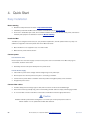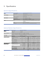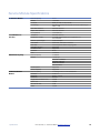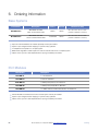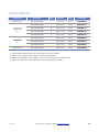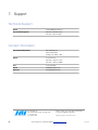
1
RLH Industries, Inc.
iMux Fiber Optic
Multiplexer System
Quick Start Guide
QS-001 2014A-0911
RLH Industries, Inc.
Copyright © 2013 RLH Industries, Inc. All rights reserved.
No part of this document may be copied or distributed without
permission.
The RLH logo may not be used for commercial purposes without the
prior written consent of RLH and may constitute trademark infringement.
Other company and product names mentioned herein are trademarks of
their respective companies. Mention of third-party products is for
informational purposes only and constitutes neither an endorsement nor
a recommendation. RLH assumes no responsibility with regard to the
performance or use of these products.
The information contained in this document is the property of RLH
Industries, Inc. and may not be reproduced or disseminated to third
parties without the express written permission of RLH.
Every effort has been made to ensure that the information in this manual
is accurate. RLH is not responsible for printing or clerical errors. Because
we are constantly seeking ways to improve our products, specifications
and information contained in this document are subject to change
without notice.
RLH Industries, Inc.
936 North Main Street
Orange,CA 92867
Ph. 714-532-1672
email: [email protected]
www.fiberopticlink.com
2
RLH Industries, Inc. • 866-DO-FIBER • www.fiberopticlink.com
Contents
Contents
1. Important Information
Intended Audience
5
Conventions
5
General Safety Practices
5
2. Introduction
Product Description
6
Standard Features
6
Application Diagrams
7
Front Panel
8
Front Panel LEDs 8
Module Status LEDs
9
LAN/MGMT Port LEDs 9
Optical Module LEDs 9
Rear Panel
10
4 Channel E1 Module
10
4 Channel T1 Module
10
4 Channel RS-232 Module
11
4 Channel V.35 Module
11
4 Channel Analog Phone (POTS) Modules
12
4 Channel 2/4 Wire Analog Data/Audio/SCADA Module
13
4 Channel 2/4 Wire Analog Data/Audio/SCADA/E&M Module
13
Setting E&M Jumpers and Switches
14
Acronyms 16
3. Before Installing
Observe Special Handling Requirements
Contents
17
Be careful when handling electronic components
17
Guidelines for handling terminated fiber cable
17
RLH Industries, Inc. • 866-DO-FIBER • www.fiberopticlink.com 3
Prepare for Installation
18
Check for shipping damage
18
Verify system contents 18
Verify matching optical module and fiber modes
18
Site Requirements
18
Site selection
18
Typical application environments 19
Required power sources
19
Test Equipment
19
For T1 service
19
For analog phone service (POTS)
19
For RS-232 service
19
4. Quick Start
Easy Installation
20
Before starting
20
Install the iMux
20
Connect power
20
Connect fiber cables 20
Connect ethernet cables 21
Connect data/phone equipment
21
Start the system
21
5. Specifications
General Specifications
22
Optical Module Specifications 22
Service Module Specifications
23
6. Ordering Information
Base Systems
24
Port Modules 24
Optical Modules
25
7. Support
4
Technical Support
26
Contact Information
26
RLH Industries, Inc. • 866-DO-FIBER • www.fiberopticlink.com
Contents
1. Important Information
Intended Audience
This manual is intended for use by knowledgeable telco/network installation, operation and repair personnel.
Every effort has been made to ensure the accuracy of the information in this manual is accurate. However, due to
constant product improvement, specifications and information contained in this document are subject to change
without notice. Please refer to the iMux User Guide for additional information.
Conventions
Symbols for notes, attention, and caution are used throughout this manual to provide readers with additional
information, advice when special attention is needed, and caution to prevent injury or equipment damage.
Notes: Helpful information to assist in installation or operation.
Attention: information essential to installation or operation.
Caution: Important information that may result in equipment damage or injury if ignored.
General Safety Practices
The equipment discussed in this manual may require tools designed for the purpose being described. RLH
recommends that installation and service personnel be familiar with the correct handling and use of any
equipment used, and follow all safety precautions including the use of protective personal equipment as required.
Caution - Severe Shock Hazard
•
Never install during a lightning storm or where unsafe high voltages are present.
•
Active T1 lines carry high DC voltages up to 56V. Use caution when handling T1 wiring.
Laser Safety
•
Radiation emitted by laser devices is dangerous to to human eyes.
•
Avoid eye exposure to direct or indirect radiation.
•
Do not operate without fiber cable attached or dust caps installed.
Important Information RLH Industries, Inc. • 866-DO-FIBER • www.fiberopticlink.com
5
2. Introduction
Product Description
The iMux is a powerful fiber optic modular multiplexer capable of providing up to 16 channels of T1, RS232, 2/4
wire data and analog phone FXO/FXS services, plus four built-in 10/100M Ethernet ports, over a single fiber.
These services are supplied by the modules, up to four, that each offer four lines of communication and may be
installed in any combination. Spares or add-on modules may be ordered separately and are field installable. The
optical modules are available in both dual fiber and single bi-directional fiber (WDM), and up to 2 optical modules
may be installed, providing 1+1 hot-swappable optical protection and making the best use of fiber availability.
The iMux may be managed through SNMP, web Interface, craft port or LCD/menu keys on the front panel. It also
has an external alarm port for alarm input monitoring, as well as 4 programmable alarm contacts. The system
provides local/remote loopback functions that are ideal for network testing and maintenance. The iMux takes up
1RU and comes complete with EIA19” and 23” rack ears, or it may be used on a desktop or shelf.
Standard Features
6
•
Multiplexes up to 16 voice and data channels plus Ethernet over a single fiber
•
Up to 4 modules (each with 4 lines) may be used in any combination to mix and match services
•
Convenient front LED status indicators
•
T1, RS232, POTS, & 2/4 wire Data service modules
•
4 built-in 10/100 Ethernet ports
•
Aggregated Ethernet throughput up to 100Mbps
•
Optical module auto laser shutdown (ALS), hot swappable 1+1 protection
•
Alarm relay has major and minor alarms (audible and visible alarm output)
•
Supports SNMP , HTTP / FTP / TFTP remote software upgradeable
•
Supports TELNET function to configure and monitor local and remote devices through TCP/IP network
•
Available with ringdown circuit operation
•
Redundant 48VDC or AC/DC powering options
RLH Industries, Inc. • 866-DO-FIBER • www.fiberopticlink.com
Introduction
Application Diagrams
POTS
(FXO)
T1
2/4 Wire
Data
POTS
(FXS)
T1
2/4 Wire
Data
Fiber Optic Cable
Up to 74 mi. / 120km
OE1
OE2
OE1
WK
LSR
ON
TX
LOS
RX
TX
1
LOS
RX
OE2
E1/V35
WK
LSR
ON
MAJ
MAJ
MAJ
1
1
WK
1
LSR
ON
1
TX
LOS
RX
E1/V35
WK
LSR
ON
TX
1
LOS
RX
1
1
1
MAJ
MAJ
MAJ
MAJ
MAJ
MAJ
LAN3
LAN4
1
1
1
1
MAJ
MGMT
LOS/LOF/AIS
CRAFT
RST
LAN1
RLH iMux
RS-232
1
1
1
MAJ
MAJ
LAN2
PORTS
MAJ
MAJ
PORTS
MAJ
MAJ
LAN1
LAN2
LAN3
LAN4
MGMT
LOS/LOF/AIS
CRAFT
RST
RLH iMux
RS-232
Ethernet
(VLAN/QoS)
Ethernet
(VLAN/QoS)
Multiple Service Example
POTS (FXS)
up to 16 POTS Lines
POTS (FXO)
up to 16 POTS Lines
Up to 74 mi. / 120km
OE1
OE2
OE1
WK
LSR
ON
TX
LOS
RX
TX
RX
OE2
E1/V35
WK
LSR
ON
1
LOS
MAJ
MAJ
MAJ
1
1
WK
1
LSR
ON
1
TX
LOS
RX
E1/V35
WK
LSR
ON
TX
RX
1
LOS
1
1
LAN3
LAN4
MGMT
MAJ
MAJ
MAJ
MAJ
MAJ
MAJ
MAJ
1
MAJ
LAN2
1
1
1
1
PORTS
MAJ
MAJ
PORTS
MAJ
MAJ
LAN1
1
1
1
MAJ
LOS/LOF/AIS
CRAFT
RST
LAN1
RLH iMux
LAN2
LAN3
LAN4
MGMT
LOS/LOF/AIS
CRAFT
RST
RLH iMux
Ethernet
(VLAN/QoS)
Ethernet
(VLAN/QoS)
16 Channels of POTS Example
T1
Up to 16 Lines
OE1
OE2
OE1
WK
LSR
ON
TX
RX
LOS
TX
RX
OE2
E1/V35
WK
LSR
ON
1
LOS
MAJ
MAJ
MAJ
MAJ
MAJ
1
1
WK
1
LSR
ON
1
TX
RX
LOS
E1/V35
WK
LSR
ON
TX
RX
1
LOS
1
1
1
MAJ
LAN2
LAN3
LAN4
MGMT
MAJ
MAJ
MAJ
MAJ
MAJ
MAJ
1
1
1
1
1
1
1
MAJ
MAJ
LAN1
PORTS
MAJ
PORTS
Ethernet
(VLAN/QoS)
T1
Up to 16 Lines
Fiber Optic Cable
Up to 74 mi. / 120km
MAJ
LOS/LOF/AIS
CRAFT
RST
RLH iMux
LAN1
LAN2
LAN3
LAN4
MGMT
LOS/LOF/AIS
CRAFT
RST
Ethernet
(VLAN/QoS)
RLH iMux
16 Channels of T1 Example
Introduction
RLH Industries, Inc. • 866-DO-FIBER • www.fiberopticlink.com
7
Front Panel
MAJ
WK
LSR
ON
TX
RX
LOS
WK
LSR
ON
TX
RX
LOS
E1/V35
1 2 3 4
PWR
MIN
LCK
LB K
ACO
EXT CLK
SL-2100
1
2
3
RDI
4
LOS/LOF/AIS
LAN1 LAN2 LAN3 LAN4 MGMT
CRAFT
RST
Front Panel LEDs
LED
Color
Name
MAJ
RED
Major Alarm
ON condition
Major alarm event is present and
OFF condition
Normal operation
being signaled through rear panel
alarm connector.
MIN
YEL
Minor Alarm
Minor alarm event is present and
Normal operation
being signaled through rear panel
alarm connector.
LBK
YEL
Loopback
RDI
YEL
Remote Defect
Indication
PWR
GRN
Power
E1 loopback signal received
Normal operation
Indicates a failure in the remote
Normal operation
terminal.
iMux is powered and ON
iMux is powered OFF, or no
power is present
LCK
YEL
Optical Link Lock
The optical link is locked because it
Normal operation
has switched to protect line mode.
ACO
YEL
Alarm Cut Off
Normal operation
ACO Button has been
pressed. See note below.
Note: ACO Button and LED operation.
The ACO button mutes the audible alarm when a problem occurs. When the button is
pressed the ACO LED illuminates. If any newer alarm is reposted after the ACP button has
been pressed, the external alarm will activate again
8
RLH Industries, Inc. • 866-DO-FIBER • www.fiberopticlink.com
Introduction
Module Status LEDs
E1/V35
1 2 3 4
IMux slot number
N1 LAN2 LAN3 LAN4 MGMT
PWR
LCK
ACO
PORTS
MAJ
MIN
LBK
RDI
ACO
1
2
3
4
Port number on
each module
RST
CRAFT
LOS/LOF/AIS
LED
Name
Color
PORT
Installed port slot
RED
No module is installed at this port number
GRN
A module is installed at this port number
Module port status for
RED
No connection is detected to that port
any installed module
GRN
Active connection is attached to that module port
E1/V35
Condition
Note: Although the port status LEDs are labeled E1/V35, they will display the status of any module
installed except the analog phone (POTS) modules. The phone module does not display
connections made to each port on the module and the LEDs for those modules only will be
GRN when off-hook and RED when ringing.
LAN/MGMT Port LEDs
LED
Name
Color
LAN 1 ~ LAN 4
LAN port activity
YEL
Data is being received
No data is being received
GRN
Data is being sent
No data is being sent
SNMP management
YEL
Data is being received
No data is being received
port activity
GRN
Data is being sent
No data is being sent
LED
Name
Color
LSR
Laser
YEL
Laser condition is OK
Laser not operating
WK
Working
GRN
Activity over fiber
No activity over fiber
LOS
Loss of Signal
RED
Loss of fiber signal
Normal operation
MGMT
ON condition
OFF condition
Optical Module LEDs
Introduction
ON condition
OFF condition
RLH Industries, Inc. • 866-DO-FIBER • www.fiberopticlink.com
9
Rear Panel
Any of the modules may be plugged into any position, called a Tributary Slot. These are referred to as TB1~TB4.
3-2 Rear Panel
Refer to the Specifications section for additional information.
48VDC
FGND
RTN (48V
ALARM
AC 110~220V
TB1
TB2
TB3
TB4
Anyone
Modulecard
1
tributary
Anyone
Modulecard
2
tributary
Anyone
Modulecard
3
tributary
Anyone
Modulecard
4
tributary
EXT_ALM
Power Switches: On/Off switch for SL-2100
SL-2100 provides three
4 Channel
E1 Module
kinds of tributary interfaces card and
different power supply combinations with the DC/AC power supply.
Four RJ-45 connectors for input/output of 4 channels E1 signal at 120Ω.
PIN 1
PIN 8
Pin
Name
Description
1
Rx Ring
2
Rx Tip
Input to E1 Card
ch3 E1U tributary
ch1
(a)
card
3
NC
T1 100Ω
E1 120Ω
4
Ring
One DB-25 pins female connector for input/output
of Tx
4 channels
E1 signal.
5
Tx Tip
Output from E1 Card
or 120
There are two types of E1 cards for selection: 75
6
NC .
7
NC
8
NC
ch4
ch2
4 Channel T1 Module
Four RJ-45 connectors for input/output of 4 channels T1 signal at 100Ω.
PIN 1
PIN 8
ch4 T1U tributary
ch2
(b)
card
ch3
ch1
One T1DB-25
pins female connector for
100Ω
100 .
E1 120Ω
Pin
1
2
3
input/output
4
5
6
7
8
Name
Description
Rx Ring
Rx Tip
Input to T1 Card
NC
of 4 channels T1 signal
Tx Ring
Tx Tip
Output from T1 Card
NC
NC
NC
T1U
10
RLH Industries, Inc. • 866-DO-FIBER • www.fiberopticlink.com
Introduction
4 Channel RS-232 Module
4xRS-232 module, HD68 to 4 DB-9 connectors to RS-232 interface. Breakout adapter cable is included.
(f) RS232 tributary card
1
5
DB-9 Female DCE
RS232
6
9
Pin
Description
I/O
1
2
3
4
5
6
7
8
9
DCD
TXD
RXD
DTR
SG
DSR
RTS
CTS
RI
Output
Output
Input
Output
GND
Input
Output
Input
Output
Any kind of the above cards is allowed to plugged into tributary slot 1~4.
(c) 4V35
tributary card
(TB1~TB4)
4 Channel V.35 Module
4*V35 card, HD68 to 4*M34 Connectors to V.35 interface.
4xV35 module, HD68 to 4 M34 connectors to V.35 interface. Breakout adapter cable is included.
M/34 Female DCE
Pin
Signal
Description
Pin
Signal
Description
A
Chassis Ground
-
V
Receive Timing A
Out
W
Terminal Timing B
X
Receive Timing B
Y
Send Timing A
Z
N/A
AA
Send Timing B
BB
N/A
CC
N/A
DD
N/A
EE
N/A
FF
N/A
HH and FXS
N/A
PBX
JJ
N/A
same
line FXS.
KK
N/A
LL
N/A
MM
N/A
NN
N/A
In
Out
Out
Out
-
B
Signal Ground
C
Request to Send
In
D
Clear to Send
Out
E
Data Set Ready
Out
F
Data Carrier Detect
Out
H
Data Terminal Ready
In
J
Local Loop Back
Out
K
Local Test
In
(d) 4 channel FXO/FXS tributary
card N/A
L
M
N/A
N
FXS and FXO, FXO connected
to aN/Acentral office
P
Send Data A
In
connected to customer telephone,
each
line FXO raises
R
Receive Data A
Out
S
Send Data B
In
Every channel provide 64k voice
bandwidth.
T
Receive Data B
Out
U
Terminal Timing A
In
FXO
Introduction
or
the
FXS
RLH Industries, Inc. • 866-DO-FIBER • www.fiberopticlink.com
11
4 Channel Analog Phone (POTS) Modules
Analog phone uses RJ-11 connectors and are supplied as FXS/Sub side and FXO/CO side modules.
The FXO/CO module is connected to a central office or PBX, and the FXS/Sub module is connected to the
customer telephone. Each line number FXO raises the same line number FXS, and provides 64k voice bandwidth.
Use an FXS module on each end for ringdown operation where connection to phones on both ends of the system
is desired.
FXO
Analog Channel
FXS
PIN 1
PIN 4
Analog Voice
4 PIN RJ-11
Female
Analog Phone
FXO Module
Tip
2
Ring
Fiber Optic
Cable
3
iMux
PSTN or PABX 4
(Central Office)
Analog Phone
Lines
POTS
2
Description
3
Analog Phone
FXS Module
POTS
1
Pin
1
2
3
iMux
Analog
Phones
4
4 Channel Analog Phone Module
Connection Diagram
Analog Phone
FXS Module
2
3
4
iMux
POTS
Analog
Phones
Fiber Optic
Cable
POTS
1
Analog Phone
FXS Module
iMux
1
2
3
Analog
Phones
4
4 Channel Analog Phone Module
Ringdown Connection Diagram
12
RLH Industries, Inc. • 866-DO-FIBER • www.fiberopticlink.com
Introduction
4 Channel 2/4 Wire Analog Data/Audio/SCADA Module
Four Analog 2/4 Wire Data/Audio/SCADA modules use RJ-11 connectors.
Each channel has 300Hz ~ 3.4kHz bandwidth.
Analog Channel
FXO
FXS
Input
PIN 1
PIN 4
4 PIN RJ-11
Female
Output
Pin
Description
1
Tip
4
Ring
2
Tip
3
Ring
4 Channel 2/4 Wire Analog Data/Audio/SCADA/E&M Module
Four Analog 2/4 Wire Data/Audio/SCADA/E&M modules use RJ-45 connectors.
Each channel has 300Hz ~ 3.4kHz bandwidth. E&M type is set in software.
Master and Slave settings are set using the jumper and DIP switches on the module itself. Refer to the following
pages.
PIN 1
4W E&M
ch2
ch4
ch1
ch3
PIN 8
Pin
Name
Description
1
2
3
4
5
6
7
8
NC
Rx Tip
Rx Ring
Tx Ring
Tx Tip
M
E
GND
NC
Input
Input
Output
Output
M Lead
E Lead
Signal Ground
Refer to the sample E&M setting and application diagrams on the following pages.
Introduction
RLH Industries, Inc. • 866-DO-FIBER • www.fiberopticlink.com
13
Setting E&M Jumpers and Switches
Use the J2 jumper and the J4 DIP switches to set the E&M module mode to Master or Slave depending on the
placement of the iMux in the network. The diagram on the following pages will help you determine the correct
settings for your application.
Refer to the diagram below for configuration settings.
E&M Module Card
Removed from Tributary Slot
Master
2
1
S
RSN
J4
3
M
J4
Slave
ON
1 2 3 4 5 6 7 8
Slave
J2
J4
Slave
ON
Slav
Master
ON
RSN
2
1 2 3 4 5 6 7 8
ON
1 2 3
1
S
J4
J4
3
M
J4
Master
Slave
Master
Slav
J2 Jumper
J4 DIP Switch
Jumper Block
Mode
J2 Jumper
Mode
Slave
Jumper Pins 1 & 2
Slave
Switches 1~4 ON
J4 DIP Switch Setting
Switches 5~8 OFF
Master
Jumper Pins 2 & 3
Master
Switches 5~8 ON
Switches 1~4 OFF
E&M module Master and Slave settings
14
RLH Industries, Inc. • 866-DO-FIBER • www.fiberopticlink.com
Introduction
Analog E&M
4-Wire Audio Operation
PBX
Tie-Line
Cisco Equipment
Slave
Master
4 Wire E&M Card
4 Wire E&M Card
E&M
E&M
Fiber Optic
Cable
(-48V)
iMux
PBX
(-48V)
iMux
Tie-Line
Cisco Equipment
On-hook
On-hook
-48V
E
detect
7
E
Off-hook
-48V
E
7
M
6
detect
Off-hook
E
Off-hook
Off-hook
M
-48V
ptc
GND
6
M
detect
-48V
8
On-hook
On-hook
T
R
4-Wire
Audio
T1
R1
Trunk Circuit
8
ptc
2
T
3
R
5
T1
4
R1
4-Wire
Audio
4-Wire
Audio
T
2
R
3
T1
5
R1
4
Signalling Unit
Signalling Unit
4 Wire E&M Card - Slave
4 Wire E&M Card - Master
M
detect
GND
T
R
4-Wire
Audio
T1
R1
Trunk Circuit
E&M Application Diagram
Introduction
RLH Industries, Inc. • 866-DO-FIBER • www.fiberopticlink.com
15
Acronyms
Commonly used acronyms and abbreviations
Acronym/Abbreviation
B8ZS
Bipolar 8 Zero Substitution
FXO/CO
Central Office Side Equipment
FXS/Sub
Subscriber side equipment
LED
16
Description
Light Emitting Diode
RX
Receive
TX
Transmit
RED
Red LED color
YEL
Yellow LED color
GRN
Green LED color
RLH Industries, Inc. • 866-DO-FIBER • www.fiberopticlink.com
Introduction
3. Before Installing
Observe Special Handling Requirements
Be careful when handling electronic components
ATTENTION
ELECTROSTATIC
SENSITIVE
DEVICES
•
This product contains static sensitive components.
•
Handle the T1/E1 cards and optical modules by their faceplates only.
•
Follow proper electrostatic discharge procedures.
This card utilizes circuitry that can be damaged by static electricity. When transporting the card, carry it in an ESD
safe container such as the antistatic bag provided with the card. Before handling cards, discharge yourself of
static electricity by physical bodily contact with earth ground. When handling cards, hold by outer edges and
avoid touching circuitry. Failure to follow ESD precautions may cause serious damage to the card and prevent
proper operation.
Guidelines for handling terminated fiber cable
17
•
Do not bend fiber cable sharply. Use gradual and smooth bends to avoid damaging glass fiber.
•
Keep dust caps on fiber optic connectors at all times when disconnected.
•
Do not remove dust caps from unused fiber.
•
Keep fiber ends and fiber connectors clean and free from dust, dirt and debris. Contamination will cause signal loss.
•
Do not touch fiber ends.
•
Store excess fiber on housing spools or fiber spools at site
RLH Industries, Inc. • 866-DO-FIBER • www.fiberopticlink.com
Before Installing
Prepare for Installation
Check for shipping damage
Carefully unpack and inspect the unit and accessories. Contact RLH immediately if any components are
damaged or missing. Electronic components, fiber optic cable, and accessories have special handling
requirements to prevent damage and enhance system reliability.
If the iMux will be relocated in the future, save the cartons and protective packaging material.
Verify system contents
The following items are shipped with your iMux system (as applicable)
•
User manual CD and Quick Start Guide
•
AC power converter and cord
•
DB9 cable
•
T1/RS-232 breakout adapter cables
Verify matching optical module and fiber modes
Fiber mode and optical module mode must be the same.
Same Fiber Mode:
Multimode OR Single Mode
Fiber Optic
Cables
Fiber Type
Color
Identifier
Single Mode
Yellow
9/125µm
Multimode
Orange
50 /125µm, 62.5/125µm
T-1
Site Requirements
Site selection
Locate the iMux to allow easy access to the equipment. Leave at least 36 inches (90 cm) clearance in the front
and at least 4 inches (10.2 cm) at the rear.
To avoid overheating, do not block the cooling fan. Leave at least 1 inch (2.5 cm) clearance on either side of iMux.
Do not stack other equipment directly on top of the iMux when rack or shelf mounting.
18
RLH Industries, Inc. • 866-DO-FIBER • www.fiberopticlink.com
Before Installing
Typical application environments
Install the fiber optic cable prior to installing the iMux system.
Required power sources
You will need an acceptable power source. The iMux system accepts 90 ~ 240VAC (47Hz ~ 63Hz) and 12, 24 or
48VDC (9 ~ 75VDC) depending on the model.
The F.C.C. requires telecommunication equipment to withstand electrical surge that may result from lighting
strikes. This equipment has been tested and found to comply with the F.C.C. requirement. Users should follow
the precautions below to insure the safety and minimize the risk of damage to the equipment
Make sure that the AC power outlet is properly grounded. Proper grounding should include a minimum of a
grounded rod buried outside the building at least 8 feet (2.44 meters) deep.
Test Equipment
For T1 service
You will need a T1 analyzer such as a T-BERD.
Be familiar with the test settings. Some analyzers have line power and multimeter capability. For installation where
no T-1 signal is available, the analyzer must be capable of generating a quasi-random T-1 signal.
T1 Analyzer
Multimeter
OK
BATT
OK
OK
BATT
OK
Can generate a quasi-random T1 signal
For analog phone service (POTS)
You will need a working POTS line or an analog phone signal generator.
Be familiar with the test settings. Some analyzers have line power and multimeter capability. For installation where
no T-1 signal is available, the analyzer must be capable of generating a quasi-random T-1 signal.
For RS-232 service
You will need a working RS-232 interface data connection.
Before Installing
RLH Industries, Inc. • 866-DO-FIBER • www.fiberopticlink.com
19
4. Quick Start
Easy Installation
Before starting
•
Review the safety information in section 1. Important Information
•
Familiarize yourself with the iMux and it’s modules as described in section 2. Introduction
•
Know how to handle fiber optic cable, have a suitable installation environment with the correct power, and have the
necessary test equipment as described in section 3. Before Installing
Install the iMux
The iMux is pre-configured at the factory for your particular requirements, and will operate without any setup. For
additional configuration instructions please refer to the iMux User Guide.
•
Mount the iMux in a 19” equipment rack, on a shelf or table
•
Make sure the power switches are OFF
Connect power
For AC Power units
Remove power from AC mains supply. Connect the AC power cord to the terminals on the iMux and plug into
110/240VAC, 50/60Hz mains outlet.
•
Alternately, wire AC mains power directly from AC power source
For DC Power supply
•
Check that DC power source voltage matches voltage range of DC power input.
•
Remove power from the DC power source prior to connecting to the iMux.
•
Connect the DC power cables to the iMux. Check the positive and negative polarity of the connection.
•
Energize the power source.
Connect fiber cables
•
The fiber cable(s) must be the right type of cable, with the correct connectors and suitable length.
•
Attach the connector(s) carefully using care to avoid bending the fiber cable too sharply and damaging the fiber.
•
Do not touch fiber connector ends which could cause contamination and lower signal performance.
Caution
Radiation emitted by laser devices is dangerous to to human eyes. Avoid eye exposure to direct or
indirect radiation. Do not operate without fiber cable attached.
20
RLH Industries, Inc. • 866-DO-FIBER • www.fiberopticlink.com
Quick Start
Connect ethernet cables
•
Attach ethernet cables to the RJ-45 ethernet ports labeled LAN1 through LAN4 on the front panel of the iMux.
Connect data/phone equipment
Attach the breakout adapters and cables depending on your iMux module configuration.
Connect T1 cables
•
Attach the breakout adapter cable to the DB-25 connector on the T1 module.
•
Connect the RJ-45 T1 connectors to the breakout adapter cables.
Connect Analog Phone (POTS) FXO/FXS cables
•
Attach the phone cables directly to the RJ-11 connectors on the analog phone module.
Attach RS-232 Data Cables
•
Attach the breakout adapter cable to the connector on the RS-232 module.
•
Connect the RS-232 data connectors to the DB-9 connectors on the breakout adapter cable.
Attach 2/4W Data/SCADA Cables
•
Attach the data cables directly to the RJ-11 connectors on the analog phone module.
Refer to the iMux User Guide for pin out and port configuration information.
Start the system
Turn each iMux ON using the power switch on the rear panel. The system will initialize and start up. The LED
indicators on the front panel will flash during initializing and stop flashing after setup is done. The iMux is now
operational and may be configured as desired.
Refer to the iMux User Guide for additional configuration information.
Quick Start
RLH Industries, Inc. • 866-DO-FIBER • www.fiberopticlink.com
21
5. Specifications
General Specifications
Alarm
Power Supply
Environment
Other
Contact Capacity
External Alarm
AC
DC
Power consumption
Working Temp.
Working Humidity
Storage Temp., Humidity
EMI
4 relay contacts (DB-9 connector)
DB-9 connector
115/240V (90~240V) (47Hz~63Hz)
48V (36~75V)
30W maximum
0˚C ~ +50˚C (32˚F ~ 122˚F)
5% ~ 95% RH non-condensing
-20˚C ~ 60˚C (-4˚F ~ 140˚F), 5% ~ 95% RH
Comply with CISPR 22 class A (EN55022), FCC part 15 class A
MTBF
Dimensions
subpart B
48,000 hours minimum
W 17.3” x D 11.2” x H 1.75” (440 x 285 x 44.5mm)
Optical Module Specifications
Optical Interface
Module
Fiber connector
Fiber Type
Dual Fiber Optics
Single Fiber Optics
(Bi-directional)
22
Optical Source
MLM 850/1310/1550nm
System Gain
19~30dB
Data Rate
155 Mb/s
100BaseFX ports, ST, SC or FC connectors, single or multi mode
Dual fiber or single fiber (bi-directional) connectors (multimode single fiber is SC only)
Multimode
50 /125µm, 62.5/125µm
Single mode
9/125µm
Fiber Type
Multimode
Single-mode
Wavelength TX/RX (nm)
1310
850
1310~1550
1310~1550
1310~1550
Distance
2km / 1.2mi. 2km / 1.2mi. 20km / 12mi. 60km / 36mi. 120km / 74mi.
Min. TX PWR (dBm)
-18
-15
-15
-6
0
Max. TX PWR (dBm)
-10
-5
-8
-3
+5
RX Sensitivity (dBm)
-31
-27
-34
-34
-34
Link Loss Budget (dB)
13
10
19
28
34
Fiber Type
Multimode
Single-mode
Wavelength TX/RX (nm)
1310/1550
1310/1550
1310/1550
1310/1550
1550/1310
1550/1310
1550/1310
1550/1310
Distance
2km / 1.2mi.
20km / 12mi. 40km / 25mi. 60km / 36mi.
Min. TX PWR (dBm)
-18
-10
-5
-3
Max. TX PWR (dBm)
-8
-3
0
+2
RX Sensitivity (dBm)
-38
-38
-38
-38
Link Loss Budget (dB)
20
28
33
35
RLH Industries, Inc. • 866-DO-FIBER • www.fiberopticlink.com
Specifications
Service Module Specifications
T1 Interface Module
10/100M Ethernet
Interface
RS232 Module (DCE)
2/4W Data/SCADA
Module
Specifications Channel Capacity
Bit Rate
Line Code
Line Framing
Input Jitter Tolerance
Output Jitter Tolerance
Line impedance
Compliance
Configuration modes
Maximum packet length
Frame buffer
MAC Table
VLAN/QOS function
Port Rate Control
Connector
Ports
Channel Capacity
Bit Rate
Local loopback
Remote loopback
Channel capacity
Connector
Bandwidth
Impedance
Longitudinal Conversion Loss
Return Loss
Idle Channel noise
CMRR
4 x T1
1.544 Mbs
B8ZS per ANSI T1.408 and AMI
Extended superframe format (ESF 24-Frame multiframe) per
ANSI T1.408
Per AT&T TR 62411
Per AT&T TR 62411
120Ω Balanced
IEEE 802.3/802.3u
10/100M, full/half-duplex, auto-negotiation and
auto MDI/MDIX
1536/1522 Bytes
329 frames, IEEE 802.3X standard
1024-entry MAC address mapping table
Supported
Supported
RJ-45
4 Ethernet
4 x RS232
115200 bps
TXD/RXD 1.536Mbit/s
DTR/DSR 128Kbit/s
RTS/CTS 128Kbit/s
DCD/RI 64Kbit/s
Supported
Supported
4 x Analog 2 wire or 4 wire data/SCADA
4 x RJ-11
300Hz ~ 3.4KHz
600Ohm
>60dB
>30dB
75dB
>60dB
RLH Industries, Inc. • 866-DO-FIBER • www.fiberopticlink.com
23
6. Ordering Information
Base Systems
Part Number
RLH-IMUX-V-2
RLH-IMUX-A-2
Description
Power 1
Power 2
48VDC
48VDC
115/220VAC
48VDC
iMUX BASE SYSTEM
DUAL 48 VDC INPUT PWR
iMUX BASE SYSTEM
AC/DC & 48VDC INPUT PWR
Dimensions (1RU)
W17.3in x D11.2in x H1.75in
(440mm x 285mm x 44.5mm)
W17.3in x D11.2in x H1.75in
(440mm x 285mm x 44.5mm)
Optics and Service Modules are ordered separately and are pre-installed.
System is pre-configured before shipping for quick and easy operation.
2 multiplexers are required for a complete system.
Bidirectional single fiber models require an A side unit and a B side unit for a complete system.
Please contact your RLH sales representative for pricing and delivery information.
Port Modules
Part Number
Description
RLH-MM-T1
T-1 4X1 MODULE
RLH-MM-D1
R-232 4X1 MODULE
RLH-MM-AO
2 WIRE (POTS) FXO/CO 4X1 MODULE
RLH-MM-AS
2 WIRE (POTS) FXS/SUB 4X1 MODULE
RLH-MM-D2
2/4 WIRE ANALOG DATA/AUDIO/SCADA 4X1 MODULE
Service Modules are ordered at same time as base system and are pre-installed.
System is pre-configured before shipping for quick and easy operation.
Please contact your RLH sales representative for pricing and delivery information.
24
RLH Industries, Inc. • 866-DO-FIBER • www.fiberopticlink.com
Ordering
Optical Modules
Part Number
Description
Side
Distance
Fiber
Part Number
Multimode ST
iMux Optical Module
-
2 km/1.2 mi
62.5 μm
RLH-OM-04-1
iMux Optical Module
A
20km/12.4mi.
8~9 μm
RLH-OM-10-1
iMux Optical Module
B
20km/12.4mi.
8~9 μm
RLH-OM-11-1
iMux Optical Module
A
60km / 37mi.
8~9 μm
RLH-OM-14-1
iMux Optical Module
B
60km / 37mi.
8~9 μm
RLH-OM-15-1
iMux Optical Module
-
20km/12.4mi.
8~9 μm
RLH-OM-40-1
iMux Optical Module
-
60km / 37mi.
8~9 μm
RLH-OM-41-1
iMux Optical Module
-
120km / 74 mi.
8~9 μm
RLH-OM-42-1
iMux Optical Module
-
20km/12.4mi.
8~9 μm
RLH-OM-50-1
Bi-Directional
Single-mode
SC
Single-mode
SC
Single-mode ST
Optics Modules ordered at same time as base system and are pre-installed.
System is pre-configured before shipping for quick and easy operation.
Bidirectional single fiber models require an A side unit and a B side unit for a complete system
Please contact your RLH sales representative for pricing and delivery information
Ordering
RLH Industries, Inc. • 866-DO-FIBER • www.fiberopticlink.com
25
7. Support
Technical Support
Email:
[email protected]
24/7 technical support:
Toll Free 1-855-RLH-24X7
Toll Free 1-855-754-2497
Contact Information
Corporate Headquarters:
RLH Industries, Inc.
936 N. Main Street
Orange, CA 92867 USA
Phone:
(714) 532-1672
Toll Free 1-800-877-1672
Toll Free 1-866-DO-FIBER
Fax:
(714) 532-1885
Email:
[email protected]
Web site:
www.fiberopticlink.com
RLH Industries, Inc.
936 N. Main Street, Orange, CA 92867 USA
T: (714) 532-1672
F: (714) 532-1885
26
Please contact your RLH sales representative
for pricing and delivery information.
Specifications subject to change without notice.
RLH Industries, Inc. • 866-DO-FIBER • www.fiberopticlink.com
Support