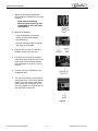
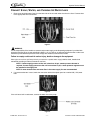
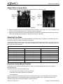
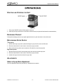
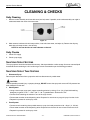
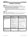
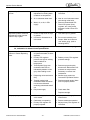
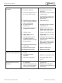
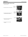
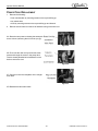
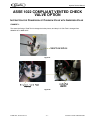
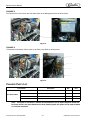
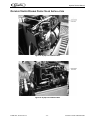
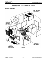
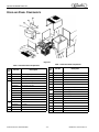
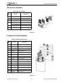
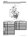
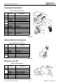
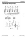
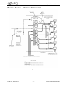
1
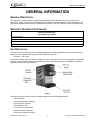
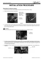
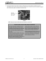
IMPULSE
Post-Mix Beverage Dispenser
(This manual applies to units which have a serial number from 89C0817IMXXX)
Service Manual
Release Date: May 2008
Publication Number: 890219401SER
Revision Date: June 01, 2012
Revision: B
Visit the IMI Cornelius web site at www.cornelius.com for all your Literature needs.
The products, technical information, and instructions contained in this manual are subject to change without notice.
These instructions are not intended to cover all details or variations of the equipment, nor to provide for every possible contingency in the installation, operation or maintenance of this equipment. This manual assumes that the person(s) working on the equipment have been trained and are skilled in working with electrical, plumbing, pneumatic,
and mechanical equipment. It is assumed that appropriate safety precautions are taken and that all local safety and
construction requirements are being met, in addition to the information contained in this manual.
This Product is warranted only as provided in Cornelius’ Commercial Warrant applicable to this Product and is subject to all of the restrictions and limitations contained in the Commercial Warranty.
Cornelius will not be responsible for any repair, replacement or other service required by or loss or damage resulting
from any of the following occurrences, including but not limited to, (1) other than normal and proper use and normal
service conditions with respect to the Product, (2) improper voltage, (3) inadequate wiring, (4) abuse, (5) accident,
(6) alteration, (7) misuse, (8) neglect, (9) unauthorized repair or the failure to utilize suitably qualified and trained persons to perform service and/or repair of the Product, (10) improper cleaning, (11) failure to follow installation, operating, cleaning or maintenance instructions, (12) use of “non-authorized” parts (i.e., parts that are not 100%
compatible with the Product) which use voids the entire warranty, (13) Product parts in contact with water or the
product dispensed which are adversely impacted by changes in liquid scale or chemical composition.
Contact Information:
To inquire about current revisions of this and other documentation or for assistance with any Cornelius product contact:
www.cornelius.com
800-238-3600
Trademarks and Copyrights:
This document contains proprietary information and it may not be reproduced in any way without permission from
Cornelius.
This document contains the original instructions for the unit described.
IMI CORNELIUS INC
101 Regency Drive
Glendale Heights, IL
Tel: + 1 800-238-3600
Printed in U.S.A.
TABLE OF CONTENTS
Safety Instructions . . . . . . . . . . . . . . . . . . . . . . . . . . . . . . . . . . . . . . . . . . . . . . . . . . . . . . . . . . . . . . . . 1
Read and Follow ALL Safety Instructions . . . . . . . . . . . . . . . . . . . . . . . . . . . . . . . . . . . . . . . . . . . . . 1
Safety Overview . . . . . . . . . . . . . . . . . . . . . . . . . . . . . . . . . . . . . . . . . . . . . . . . . . . . . . . . . . . . . 1
Recognition . . . . . . . . . . . . . . . . . . . . . . . . . . . . . . . . . . . . . . . . . . . . . . . . . . . . . . . . . . . . . . . . . 1
Different Types of Alerts . . . . . . . . . . . . . . . . . . . . . . . . . . . . . . . . . . . . . . . . . . . . . . . . . . . . . . . . . . 1
Safety Tips . . . . . . . . . . . . . . . . . . . . . . . . . . . . . . . . . . . . . . . . . . . . . . . . . . . . . . . . . . . . . . . . . . . . 1
Qualified Service Personnel . . . . . . . . . . . . . . . . . . . . . . . . . . . . . . . . . . . . . . . . . . . . . . . . . . . . . . . 1
Safety Precautions . . . . . . . . . . . . . . . . . . . . . . . . . . . . . . . . . . . . . . . . . . . . . . . . . . . . . . . . . . . . . . 2
Shipping And Storage . . . . . . . . . . . . . . . . . . . . . . . . . . . . . . . . . . . . . . . . . . . . . . . . . . . . . . . . . . . . 2
Mounting in or on a Counter . . . . . . . . . . . . . . . . . . . . . . . . . . . . . . . . . . . . . . . . . . . . . . . . . . . . . . . 2
CO2 (Carbon Dioxide) Warning . . . . . . . . . . . . . . . . . . . . . . . . . . . . . . . . . . . . . . . . . . . . . . . . . . . . 2
General Information . . . . . . . . . . . . . . . . . . . . . . . . . . . . . . . . . . . . . . . . . . . . . . . . . . . . . . . . . . . . . . . 3
General Description . . . . . . . . . . . . . . . . . . . . . . . . . . . . . . . . . . . . . . . . . . . . . . . . . . . . . . . . . . . . . 3
Warranty Reference Information . . . . . . . . . . . . . . . . . . . . . . . . . . . . . . . . . . . . . . . . . . . . . . . . . . . . 3
Unit Description . . . . . . . . . . . . . . . . . . . . . . . . . . . . . . . . . . . . . . . . . . . . . . . . . . . . . . . . . . . . . . . . . 3
Specifications . . . . . . . . . . . . . . . . . . . . . . . . . . . . . . . . . . . . . . . . . . . . . . . . . . . . . . . . . . . . . . . . . . 4
Dimensions . . . . . . . . . . . . . . . . . . . . . . . . . . . . . . . . . . . . . . . . . . . . . . . . . . . . . . . . . . . . . . . . . 4
Part Numbers . . . . . . . . . . . . . . . . . . . . . . . . . . . . . . . . . . . . . . . . . . . . . . . . . . . . . . . . . . . . . . . 4
Capacity . . . . . . . . . . . . . . . . . . . . . . . . . . . . . . . . . . . . . . . . . . . . . . . . . . . . . . . . . . . . . . . . . . . 4
Accessories . . . . . . . . . . . . . . . . . . . . . . . . . . . . . . . . . . . . . . . . . . . . . . . . . . . . . . . . . . . . . . . . . 4
Theory of Operation . . . . . . . . . . . . . . . . . . . . . . . . . . . . . . . . . . . . . . . . . . . . . . . . . . . . . . . . . . . . . . . 5
Installation . . . . . . . . . . . . . . . . . . . . . . . . . . . . . . . . . . . . . . . . . . . . . . . . . . . . . . . . . . . . . . . . . . . . . . . 6
Delivery Inspection and Unpacking . . . . . . . . . . . . . . . . . . . . . . . . . . . . . . . . . . . . . . . . . . . . . . . . . . 6
Inspection . . . . . . . . . . . . . . . . . . . . . . . . . . . . . . . . . . . . . . . . . . . . . . . . . . . . . . . . . . . . . . . . . . 6
Unpacking . . . . . . . . . . . . . . . . . . . . . . . . . . . . . . . . . . . . . . . . . . . . . . . . . . . . . . . . . . . . . . . . . . 6
Installation requirements . . . . . . . . . . . . . . . . . . . . . . . . . . . . . . . . . . . . . . . . . . . . . . . . . . . . . . . . . . 7
Requirements Summary . . . . . . . . . . . . . . . . . . . . . . . . . . . . . . . . . . . . . . . . . . . . . . . . . . . . . . . 7
Electrical Requirements . . . . . . . . . . . . . . . . . . . . . . . . . . . . . . . . . . . . . . . . . . . . . . . . . . . . . . . . . . 7
Environmental Requirements . . . . . . . . . . . . . . . . . . . . . . . . . . . . . . . . . . . . . . . . . . . . . . . . . . . . . . 7
Installation Procedure . . . . . . . . . . . . . . . . . . . . . . . . . . . . . . . . . . . . . . . . . . . . . . . . . . . . . . . . . . . . . 8
Counter-top Installation . . . . . . . . . . . . . . . . . . . . . . . . . . . . . . . . . . . . . . . . . . . . . . . . . . . . . . . . . . . 8
Connect Syrup, Water, and Carbonated Water Lines . . . . . . . . . . . . . . . . . . . . . . . . . . . . . . . . . . . 11
Check for Leaks . . . . . . . . . . . . . . . . . . . . . . . . . . . . . . . . . . . . . . . . . . . . . . . . . . . . . . . . . . . . 12
Reinstall Panels . . . . . . . . . . . . . . . . . . . . . . . . . . . . . . . . . . . . . . . . . . . . . . . . . . . . . . . . . . . . 12
Adjust Water-to-Syrup Ratio . . . . . . . . . . . . . . . . . . . . . . . . . . . . . . . . . . . . . . . . . . . . . . . . . . . 13
Adjusting Flow Rates . . . . . . . . . . . . . . . . . . . . . . . . . . . . . . . . . . . . . . . . . . . . . . . . . . . . . . . . 13
Electronic Control Board Function . . . . . . . . . . . . . . . . . . . . . . . . . . . . . . . . . . . . . . . . . . . . . . 13
Ice Bank Control . . . . . . . . . . . . . . . . . . . . . . . . . . . . . . . . . . . . . . . . . . . . . . . . . . . . . . . . . . . . 14
Carbonator Control . . . . . . . . . . . . . . . . . . . . . . . . . . . . . . . . . . . . . . . . . . . . . . . . . . . . . . . . . . 14
LED Diagnostics . . . . . . . . . . . . . . . . . . . . . . . . . . . . . . . . . . . . . . . . . . . . . . . . . . . . . . . . . . . . 14
Operations . . . . . . . . . . . . . . . . . . . . . . . . . . . . . . . . . . . . . . . . . . . . . . . . . . . . . . . . . . . . . . . . . . . . . . 15
Starting and Stopping the Unit . . . . . . . . . . . . . . . . . . . . . . . . . . . . . . . . . . . . . . . . . . . . . . . . . . . . 15
Dispensing Product . . . . . . . . . . . . . . . . . . . . . . . . . . . . . . . . . . . . . . . . . . . . . . . . . . . . . . . . . . . . . 15
Replenishing Syrup Supply . . . . . . . . . . . . . . . . . . . . . . . . . . . . . . . . . . . . . . . . . . . . . . . . . . . . . . . 15
Adjustments . . . . . . . . . . . . . . . . . . . . . . . . . . . . . . . . . . . . . . . . . . . . . . . . . . . . . . . . . . . . . . . . . . 15
Water-to-Syrup Ratio Adjustment . . . . . . . . . . . . . . . . . . . . . . . . . . . . . . . . . . . . . . . . . . . . . . . 15
Cleaning & Checks . . . . . . . . . . . . . . . . . . . . . . . . . . . . . . . . . . . . . . . . . . . . . . . . . . . . . . . . . . . . . . . 16
Daily Cleaning . . . . . . . . . . . . . . . . . . . . . . . . . . . . . . . . . . . . . . . . . . . . . . . . . . . . . . . . . . . . . . 16
Daily Checks . . . . . . . . . . . . . . . . . . . . . . . . . . . . . . . . . . . . . . . . . . . . . . . . . . . . . . . . . . . . . . . 16
Sanitizing Syrup Systems . . . . . . . . . . . . . . . . . . . . . . . . . . . . . . . . . . . . . . . . . . . . . . . . . . . . . . . . 16
Sanitizing Syrup Tank Systems . . . . . . . . . . . . . . . . . . . . . . . . . . . . . . . . . . . . . . . . . . . . . . . . . . . 16
Sanitizing Bag-in-Box Syrup System . . . . . . . . . . . . . . . . . . . . . . . . . . . . . . . . . . . . . . . . . . . . . . . 17
Double Liquid Check Valve Inspection & Cleaning . . . . . . . . . . . . . . . . . . . . . . . . . . . . . . . . . . . . . 17
Condenser Cleaning . . . . . . . . . . . . . . . . . . . . . . . . . . . . . . . . . . . . . . . . . . . . . . . . . . . . . . . . . 18
Guide to Service . . . . . . . . . . . . . . . . . . . . . . . . . . . . . . . . . . . . . . . . . . . . . . . . . . . . . . . . . . . . . . . . . 19
Preventative Maintenance . . . . . . . . . . . . . . . . . . . . . . . . . . . . . . . . . . . . . . . . . . . . . . . . . . . . . . . 19
Sanitizing . . . . . . . . . . . . . . . . . . . . . . . . . . . . . . . . . . . . . . . . . . . . . . . . . . . . . . . . . . . . . . . . . . . . 19
Double Liquid Check Valve Inspection & Cleaning . . . . . . . . . . . . . . . . . . . . . . . . . . . . . . . . . . . . . 19
Check for Leaks . . . . . . . . . . . . . . . . . . . . . . . . . . . . . . . . . . . . . . . . . . . . . . . . . . . . . . . . . . . . . . . 19
Check Ratio . . . . . . . . . . . . . . . . . . . . . . . . . . . . . . . . . . . . . . . . . . . . . . . . . . . . . . . . . . . . . . . . . . 19
Clean Condenser . . . . . . . . . . . . . . . . . . . . . . . . . . . . . . . . . . . . . . . . . . . . . . . . . . . . . . . . . . . . . . 19
Clean Bib Connectors . . . . . . . . . . . . . . . . . . . . . . . . . . . . . . . . . . . . . . . . . . . . . . . . . . . . . . . . . . . 19
Adjustments . . . . . . . . . . . . . . . . . . . . . . . . . . . . . . . . . . . . . . . . . . . . . . . . . . . . . . . . . . . . . . . . . . 20
CO2 Connection . . . . . . . . . . . . . . . . . . . . . . . . . . . . . . . . . . . . . . . . . . . . . . . . . . . . . . . . . . . . . . . 20
Primary And secondary CO2 Regulator Settings . . . . . . . . . . . . . . . . . . . . . . . . . . . . . . . . . . . . . . 20
Trouble Shooting . . . . . . . . . . . . . . . . . . . . . . . . . . . . . . . . . . . . . . . . . . . . . . . . . . . . . . . . . . . . . . . . 21
Component Service . . . . . . . . . . . . . . . . . . . . . . . . . . . . . . . . . . . . . . . . . . . . . . . . . . . . . . . . . . . . . . 26
Carbonator Pump Replacement . . . . . . . . . . . . . . . . . . . . . . . . . . . . . . . . . . . . . . . . . . . . . . . . . . . 26
Pump Motor Replacement . . . . . . . . . . . . . . . . . . . . . . . . . . . . . . . . . . . . . . . . . . . . . . . . . . . . . . . 27
Agitator Motor Replacement . . . . . . . . . . . . . . . . . . . . . . . . . . . . . . . . . . . . . . . . . . . . . . . . . . . . . . 28
Controller Board Replacement . . . . . . . . . . . . . . . . . . . . . . . . . . . . . . . . . . . . . . . . . . . . . . . . . . . . 28
Condenser Fan Motor Replacement . . . . . . . . . . . . . . . . . . . . . . . . . . . . . . . . . . . . . . . . . . . . . . . . 29
Power Cord Replacement . . . . . . . . . . . . . . . . . . . . . . . . . . . . . . . . . . . . . . . . . . . . . . . . . . . . . . . . 30
ASSE 1022 Compliant Vented Check Valve Option . . . . . . . . . . . . . . . . . . . . . . . . . . . . . . . . . . . . . 31
Instruction for Conversion of Chudnow Valve with Anderson Valve . . . . . . . . . . . . . . . . . . . . . . . . 31
Changed Parts List . . . . . . . . . . . . . . . . . . . . . . . . . . . . . . . . . . . . . . . . . . . . . . . . . . . . . . . . . . . . . 32
Olympus Vented Double Check Valve Installation . . . . . . . . . . . . . . . . . . . . . . . . . . . . . . . . . . . . . 33
Illustrated Parts List . . . . . . . . . . . . . . . . . . . . . . . . . . . . . . . . . . . . . . . . . . . . . . . . . . . . . . . . . . . . . . 31
General Assembly . . . . . . . . . . . . . . . . . . . . . . . . . . . . . . . . . . . . . . . . . . . . . . . . . . . . . . . . . . . . . . 31
Hood and Panel Components . . . . . . . . . . . . . . . . . . . . . . . . . . . . . . . . . . . . . . . . . . . . . . . . . . . . . 32
Coil and Carbonator Components . . . . . . . . . . . . . . . . . . . . . . . . . . . . . . . . . . . . . . . . . . . . . . . . . 33
Pump and Motor Assembly . . . . . . . . . . . . . . . . . . . . . . . . . . . . . . . . . . . . . . . . . . . . . . . . . . . . . . . 34
Manifold Components . . . . . . . . . . . . . . . . . . . . . . . . . . . . . . . . . . . . . . . . . . . . . . . . . . . . . . . . . . . 34
Water Coil Assembly . . . . . . . . . . . . . . . . . . . . . . . . . . . . . . . . . . . . . . . . . . . . . . . . . . . . . . . . . . . . 35
Carbonator Tank Assembly . . . . . . . . . . . . . . . . . . . . . . . . . . . . . . . . . . . . . . . . . . . . . . . . . . . . . . 35
Refrigeration Assembly . . . . . . . . . . . . . . . . . . . . . . . . . . . . . . . . . . . . . . . . . . . . . . . . . . . . . . . . . . 36
Platform, Compressor and Evaporator Components . . . . . . . . . . . . . . . . . . . . . . . . . . . . . . . . . . . 37
Condenser Components . . . . . . . . . . . . . . . . . . . . . . . . . . . . . . . . . . . . . . . . . . . . . . . . . . . . . . . . . 38
Agitator Motor Components . . . . . . . . . . . . . . . . . . . . . . . . . . . . . . . . . . . . . . . . . . . . . . . . . . . . . . 38
Optional Light Kit . . . . . . . . . . . . . . . . . . . . . . . . . . . . . . . . . . . . . . . . . . . . . . . . . . . . . . . . . . . . . . . 38
Reference Material . . . . . . . . . . . . . . . . . . . . . . . . . . . . . . . . . . . . . . . . . . . . . . . . . . . . . . . . . . . . . . . 39
Wiring Diagram . . . . . . . . . . . . . . . . . . . . . . . . . . . . . . . . . . . . . . . . . . . . . . . . . . . . . . . . . . . . . . . . 39
Plumbing Diagram — Internal Carbonator . . . . . . . . . . . . . . . . . . . . . . . . . . . . . . . . . . . . . . . . . . . 40
Plumbing Diagram — External Carbonator . . . . . . . . . . . . . . . . . . . . . . . . . . . . . . . . . . . . . . . . . . . 41
Impulse Service Manual
SAFETY INSTRUCTIONS
READ AND FOLLOW ALL SAFETY INSTRUCTIONS
Safety Overview
•
Read and follow ALL SAFETY INSTRUCTIONS in this manual and any warning/caution labels on the unit (decals, labels or
laminated cards).
•
Read and understand ALL applicable OSHA (Occupational Safety and Health Administration) safety regulations before
operating this unit.
Recognition
Recognize Safety Alerts
!
This is the safety alert symbol. When you see it in this manual or on the unit,
be alert to the potential of personal injury or damage to the unit.
DIFFERENT TYPES OF ALERTS
! DANGER:
Indicates an immediate hazardous situation which if not avoided WILL result in serious injury, death or equipment
damage.
! WARNING:
Indicates a potentially hazardous situation which, if not avoided, COULD result in serious injury, death, or equipment
damage.
! CAUTION:
Indicates a potentially hazardous situation which, if not avoided, MAY result in minor or moderate injury or equipment
damage.
SAFETY TIPS
•
Carefully read and follow all safety messages in this manual and safety signs on the unit.
•
Keep safety signs in good condition and replace missing or damaged items.
•
Learn how to operate the unit and how to use the controls properly.
•
Do not let anyone operate the unit without proper training. This appliance is not intended for use by very young children or
infirm persons without supervision. Young children should be supervised to ensure that they do not play with the appliance.
•
Keep your unit in proper working condition and do not allow unauthorized modifications to the unit.
QUALIFIED SERVICE PERSONNEL
! WARNING:
Only trained and certified electrical, plumbing and refrigeration technicians should service this unit. ALL WIRING
AND PLUMBING MUST CONFORM TO NATIONAL AND LOCAL CODES. FAILURE TO COMPLY COULD
RESULT IN SERIOUS INJURY, DEATH OR EQUIPMENT DAMAGE.
Publication Number: 890219401SER
-1-
© 2008-2012, IMI Cornelius Inc.
Impulse Service Manual
SAFETY PRECAUTIONS
This unit has been specifically designed to provide protection against personal injury. To ensure continued protection
observe the following:
! WARNING:
Disconnect power to the unit before servicing following all lock out/tag out procedures established by the user. Verify
all of the power is off to the unit before any work is performed.
Failure to disconnect the power could result in serious injury, death or equipment damage.
! CAUTION:
Always be sure to keep area around the unit clean and free of clutter. Failure to keep this area clean may result in
injury or equipment damage.
SHIPPING AND STORAGE
! CAUTION:
Before shipping, storing, or relocating the unit, the unit must be sanitized and all sanitizing solution must be drained
from the system. A freezing ambient environment will cause residual sanitizing solution or water remaining inside the
unit to freeze resulting in damage to internal components.
MOUNTING IN OR ON A COUNTER
! WARNING:
When installing the unit in or on a counter top, the counter must be able to support a weight in excess of 440 lbs. to
insure adequate support for the unit. FAILURE TO COMPLY COULD RESULT IN SERIOUS INJURY, DEATH OR
EQUIPMENT DAMAGE.
NOTE: Many units incorporate the use of additional equipment such as icemakers. When any
addition equipment is used you must check with the equipment manufacturer to determine the
additional weight the counter will need to support to ensure a safe installation.
CO2 (CARBON DIOXIDE) WARNING
! DANGER:
CO2 displaces oxygen. Strict attention MUST be observed in the prevention of CO2 gas leaks in the entire CO2 and
soft drink system. If a CO2 gas leak is suspected, particularly in a small area, IMMEDIATELY ventilate the
contaminated area before attempting to repair the leak. Personnel exposed to high concentrations of CO2 gas
experience tremors which are followed rapidly by loss of consciousness and DEATH.
© 2008-2012, IMI Cornelius Inc.
-2-
Publication Number: 890219401SER
Impulse Service Manual
GENERAL INFORMATION
GENERAL DESCRIPTION
This manual is a guide for installing, operating, and maintaining this equipment. This section gives the Unit
Description, Theory of Operation, and Design Data for Impulse Post-Mix Beverage Over counter Dispenser. This
Unit must be installed and serviced by a qualified Service Person. This Unit Contains no User serviceable parts.
WARRANTY REFERENCE INFORMATION
Warranty Registration Date
(to be filled out by customer)
Unit Part Number:
Serial Number:
Install Date:
Local Authorized Serviced Center:
UNIT DESCRIPTION
The Impulse over the counter, post-mix, beverage dispenser is compact, lightweight, and can be ordered with or
without a built-in carbonator. Syrup pump kits are available for the units.
• Impulse — 5 & 6 valve
Impulse units may be island mounted or installed on a front or rear counter. The 1/3 H.P. refrigeration deck is easily
removed for service and maintenance. Adjustable water fl ow regulators and syrup fl ow regulators, located on
dispensing valves, are easily accessible.
Figure 1.
The Impulse over the counter, post-mix, beverage dispenser offers the following features:
• Key-lock switch
• Lighted merchandiser (optional)
• Syrup pump kit (optional)
• Removable drip tray
• 5 or 6 valves on Impulse unit
• Built-in carbonator (optional)
• Removable refrigeration deck(s)
© 2008-2012, IMI Cornelius Inc.
-3-
Publication Number: 890219401SER
Impulse Service Manual
SPECIFICATIONS
Dimensions
Height
27 inches
685 mm
Width
16 inches
406 mm
Depth
26 7/8 inches
682 mm
Shipping Weight (approx.)
120 pounds
55 kg
Water Bath Size
17 gal (US)
64 l
Ice Bank Size
30 lb
13.6 kg
Part Numbers
60 Hz Model, 120 VAC see nameplate
60 Hz Model, 230 VAC see nameplate
50 Hz Model, 230 VAC see nameplate
Capacity
Assuming:
– a 3 oz./sec. (85g / sec.) dispensing rate
– a 75°F (24°C) ambient temperature
– four 12-oz. (340g) drinks per minute
– drinks dispensed at 40° F (5 °C) or below
Capacities by unit are:
Impulse unit, 120 volt, 60 Hz, 200 drinks / hour
Impulse unit, 230 volt, 50 Hz, 170 drinks / hour
Accessories
Legs (optional), order 4 ea. — P/N 500134
Publication Number: 890219401SER
-4-
© 2008-2012, IMI Cornelius Inc.
Impulse Service Manual
THEORY OF OPERATION
NOTE: The Unit Is Factory Set To Dispense Non-carbonated Water And Carbonated Water As Per
Customer’s Requirement. It Is Available To Dispense At Most 3 Non-carbonated Waters With
Carbonated Water Dispensing From The Remaining Valve(S). Non-carbonated Water Dispensing
Valve(S) May Be Converted To Also Dispense Carbonated Drink(S).
A CO2 cylinder delivers carbon dioxide (CO2) gas through adjustable CO2 regulators to the applicable syrup tanks
or bag-in-box syrup pumps and also the integral (built-in) carbonator. Plain water enters the integral carbonator
carbonated water tank and is carbonated by CO2 gas pressure also entering the water tank. When dispensing
valve is opened, CO2 gas pressure exerted upon the applicable syrup tank contents or bag-in-box syrup pump
pushes syrup from the syrup supply, through the Unit syrup cooling coil, and on to the dispensing valve.
Carbonated water is pushed from the integral carbonator carbonated water tank by CO2 gas head pressure and is
pushed through the carbonated water manifold to the dispensing valve. Syrup and carbonated water meet
simultaneously at the dispensing valve resulting in a carbonated drink being dispensed. A still (non-carbonated)
drink is dispensed in the same manner as the carbonated drink except plain water is substituted for carbonated
water.
© 2008-2012, IMI Cornelius Inc.
-5-
Publication Number: 890219401SER
Impulse Service Manual
INSTALLATION
! WARNING:
Only trained and certified electrical, plumbing and refrigeration technicians should service this unit.
All wiring and plumbing must conform to national and local codes. Failure to comply could
result in serious injury, death or equipment damage.
!
WARNING:
It is the responsibility of the installer to ensure that the water supply to the dispensing equipment is provided with
protection back flow by an air gap as defined in ANSI A 112.1.2-1979; or an approved vacuum breaker or other such
method as proved effective by test and must comply with all federal, state and local codes.
Failure to comply could result in serious injury, death or damage to the equipment.
Water pipe connections and fixtures directly connected to a potable water supply shall be sized, installed and
maintained according to Federal, State and Local laws.
DELIVERY INSPECTION AND UNPACKING
Inspection
Upon delivery inspect the unit for damage or irregularities and immediately report problems to the delivering carrier
and file a claim with that carrier.
Unpacking
1. Remove shipping tape and other packing material.
2. Unpack the loose parts and make sure all items are present.
Table 1. Loose Shipped Parts
Sl. No.
Name
Qty.
1
Cup rest
1
2
Drip tray
1
3
Drain hose
1
4
Hose clamp
1
5
Decal Kit
1
6
890219401SER- Service Manual
1
Publication Number: 890219401SER
-6-
© 2008-2012, IMI Cornelius Inc.
Impulse Service Manual
INSTALLATION REQUIREMENTS
Requirements Summary
Weight
counter must be level and able to support 400 lbs. (180 kg)
Environment
indoor installation only
Temperature
40° F to 110° F (4° C - 43° C) ambient temperature
Clearance
18 - inches (0.45 m) above 6 - inches (0.15 m) on sides and rear
CO2
75 psi (5 bar) pre-set regulator on unit with internal carbonator
Syrup
60 psi (4 bar)
Water
50 psi (3.5 bar) maximum
Electrical
see nameplate on unit for electrical requirements
ELECTRICAL REQUIREMENTS
Before connecting electrical power to the unit refer to nameplate to verify power requirements.
!
DANGER:
To avoid possible serious injury or death the ELCB (earth leakage circuit breaker) must be
installed in electrical circuit of all 50 Hz units.
! WARNING:
To avoid possible electrical shock the unit must be electrically grounded using the green grounding screw provided
inside the electrical contactor box.
! CAUTION:
The wiring must be properly grounded and connected through a 10 - amp disconnect switch (slow–blow fuse or
equivalent HVAC / R circuit breaker). ALL WIRING MUST CONFORM TO NATIONAL AND LOCAL CODES. MAKE
SURE UNIT IS PROPERLY GROUNDED.
ENVIRONMENTAL REQUIREMENTS
Ambient (room) temperature MUST NOT EXCEED 110° F (43° C) Temperatures in excess of 110° F (43° C) will
void the factory warranty and may eventually result in refrigeration system failure.
! CAUTION:
To avoid overheating and damaging to the unit, and voiding the warranty, there must be at least 6 - inch (0.15 m) of
clearance on all sides and 18 - inch (0.45 m) on the top of the unit.
! CAUTION:
This unit is designed for indoor installation only (in non harsh environments).
! CAUTION:
If the unit is exposed to freezing temperature, water in the unit will freeze and may damage the unit.
! CAUTION:
Avoid spillage into the top vents.
© 2008-2012, IMI Cornelius Inc.
-7-
Publication Number: 890219401SER
Impulse Service Manual
INSTALLATION PROCEDURE
COUNTER-TOP INSTALLATION
1. Place the unit on a level counter capable of supporting at least 400 pounds ( 180 kg ).
2. Remove drip tray and front access panel.
Figure 2.
3. Turn power switch off then remove screw located next to the power switch and the screw at top of front panel.
Next, remove front panel, disconnect wires to valve key lock switch, and peal back magnetic decals from the
top. Lift off top center section.
! CAUTION:
Make sure that the power to the unit is disconnected (unplugged) before removing the covers.
Figure 3.
4. Pull water, syrup, and CO2 lines through counter or wall. To comply with NSF International requirements the
unit must be sealed to the counter top and all access holes in the unit base must be sealed, or the unit can be
installed using the optional 4 legs (P/N 500134). Caulk/seal the unit to the counter using Dow Corning RTV 731
or equivalent approved sealant.
5. Pull plastic “wire tie” to remove hitch pin from condenser fan motor assembly (this pin is only needed during
shipping).
Figure 4.
Publication Number: 890219401SER
-8-
© 2008-2012, IMI Cornelius Inc.
Impulse Service Manual
6. Fill the water bath with clean water around the carbonator tank or bend back the insulation on the noncarbonated unit until it comes out the overflow tube. Make sure the overflow ow tube is not blocked or plugged.
Use low-mineral tap water, not distilled or deionized water.
Figure 5.
NOTE: Water bath must be filled with water before the unit will run.
GLOBAL ICE BANK CONTROL (GIBO) THEORY OF OPERATION
Once electrical power is supplied to the Unit,
the agitator motor will start. There will be a
three-minute time delay before the refrigeration
compressor and the condenser fan motor will
start. This three-minute time delay will take
place each time electrical power to the Unit is
interrupted.
becomes thick enough, it covers the three
stainless-steel pins on the ice bank control
probe. The control module senses there is
enough ice and turns the refrigeration compressor and the condenser fan motor off.
The Unit remains turned off until the ice bank
control three stainless-steel pins are free of
The Unit will continue to operate until ice cov- ice. Once this happens, the ice bank control
ers all three stainless-steel pins on the ice bank module starts the refrigeration compressor
control probe. The ice bank control module
and the condenser fan motor.
senses this by measuring the difference in
electrical resistance between the water and the
ice. When the ice on the evaporator coil
© 2008-2012, IMI Cornelius Inc.
-9-
Publication Number: 890219401SER
Impulse Service Manual
7. Make sure that the electrical power
circuit breaker is switched off or the fuse
removed.
NOTE: Before connecting
electrical power to the unit, refer
to nameplate to verify the power
requirements.
A. Remove the following:
• front merchandiser by removing
screws on the top and lifting up
• key switch wires
• hood by removing screws on the top
and lifting up and forward.
B. Remove second valve from the left to
facilitate routing of the new cord.
C. First route the new cord up behind the
valve panel and through the cutout in the
pump deck. Use the already attached
wire tie/fastener on the deck to secure
the cord.
D. Connect cord to the receptacle on the
refrigeration deck.
E. Turn the circuit breaker on and then the
units power switch. Check to see that the
agitator motor has started. After about
three minutes the compressor should
start. If the agitator or compressor do not
start call Technical Services.
Figure 6.
Publication Number: 890219401SER
- 10 -
© 2008-2012, IMI Cornelius Inc.
Impulse Service Manual
CONNECT SYRUP, WATER, AND CARBONATED WATER LINES
1. Route syrup and plain water lines from the back side of the unit and under the unit to the front. Connect them
to the appropriate inlet connections.
Figure 7.
! WARNING:
It is the responsibility of the installer to ensure that the water supply to the dispensing equipment is provided with
protection back flow by an air gap as defined in ANSI A 112.1.2-1979; or an approved vacuum breaker or other such
method as proved effective by test and must comply with all federal, state and local codes.
Failure to comply could result in serious injury, death or damage to the equipment.
Water pipe connections and fixtures directly connected to a potable water supply shall be sized, installed and
maintained according to Federal, State and Local laws.
NOTE: .If water supply pressure to the unit is less than 40 psi, a water pressure booster is
required. If water supply pressure to the unit is more than 50 psi, a water pressure regulator must
be installed in the supply line.
NOTE: A water shutoff valve and water filter in the water supply line are recommended.
2. If a remote carbonator is used, make the connection behind the splash panel to a marked 3/8 (.375) water
tube.
Figure 8.
If the unit has a built-in carbonator, connect the water line to the pump.
Figure 9.
© 2008-2012, IMI Cornelius Inc.
- 11 -
Publication Number: 890219401SER
Impulse Service Manual
3. Connect optional drip tray drain hose (if used). Be sure the knock-out in the drip pan has been removed if drain
hose is used.
4. If the unit has a built-in carbonator, connect the CO2 lines. Be sure the water and CO2 are on CO2 should be
set at 75 psi (5.25 bar) maximum. Higher CO2 pressure will result in LOWER carbonation.
Figure 10.
Bleed the air out of the carbonator by pulling up on the metal ring on the bleed valve. Bleed each valve into a bucket
until water comes out for 2-3 seconds.
NOTE: The CO2 inlet fitting is sealed inside the carbonator with an O-ring. This fitting rotates freely
and must be held by a second wrench while securing the CO2 inlet line.
5. If remote carbonator is used, be sure it is on. Bleed each valve into a bucket until carbonated water comes out.
6. Be sure that all syrup sources are connected and on. Bleed each valve into a bucket until syrup comes out.
7. Reinstall drip tray and position water bath overflow hose in drip tray indent.
8. Check the system for gas leaks by pressurizing the system and then turning off the cylinder valve. Wait a
couple of minutes and check the cylinder gauge to see if the pressure has dropped.
9. Check the system for water and syrup leaks.
Check for Leaks
1. Bleed air from the lines by activating dispensing valves.
2. Remove air from carbonator (if unit has built-in carbonator) by opening safety relief valve until water escapes.
3. Check the system for gas leaks by pressurizing the system and then turning off the cylinder valve. Wait a
couple of minutes and check the cylinder gauge to see if the pressure has dropped.
4. Check the system for water and syrup leaks.
Reinstall Panels
Reinstall top and front vented panels as well as the front stainless steel panel.
Publication Number: 890219401SER
- 12 -
© 2008-2012, IMI Cornelius Inc.
Impulse Service Manual
Adjust Water-to-Syrup Ratio
1. Remove valve front cover and install syrup diversion assembly in place of nozzle.
Figure 11.
2. Adjust carbonated water fl ow to the desired rate (such as 2.50 oz. / sec.) (70g / sec.). Turn the adjuster 1/4 of
a turn at a time and recheck the fl ow. To increase fl ow turn clockwise.
3. Adjust the syrup-to-water ratio of each valve using the syrup adjuster on the left side of each valve. Hold cup
under valve and dispense beverage for a specific time (such as 4 seconds).
Adjusting Flow Rates
Flow rates of the water and syrup are adjusted based on the desired ratio. For example: if the desired ratio is 5:1,
then the fl ow rate of the water is 5 times that of the syrup.
If the desired finished drink flow rate is 3.0 ounces per second, then the water flow rate is 2.5 oz./sec. (70 g / sec.)
and the syrup flow rate is 0.5 oz./sec. (14 g / sec.) (The water at 2.5 oz./sec. (70 g / sec.) is five times the 0.5 oz./
sec. (14 g / sec.) syrup flow rate.)
Flow Rates Based on 5:1 Ratio
Finished Drink oz./sec.
Water oz./sec.
Syrup oz./sec.
1.5 (42 g/sec.)
1.25 (35 g/sec.)
.25 (7 g/sec.)
2.0 (56 g/sec.)
1.67 (47 g/sec.)
.33 (9.4 g/sec.)
2.5 (70 g/sec.)
2.08 (60 g/sec.)
.42 (12 g/sec.)
3.0 (85 g/sec.)
2.5 (70 g/sec.)
.50 (14 g/sec.)
3.5 (99 g/sec.)
2.92 (83 g/sec.)
.58 (16.5 g/sec.)
4.0 (113 g/sec.)
3.33 (95 g/sec.)
.67 (19 g/sec.)
4.5 (128 g/sec.)
3.75 (105 g/sec.)
.75 (21 g/sec.)
Electronic Control Board Function
An integrated circuit board and microprocessor are used to control the electrical functions of the Impulse™
beverage dispenser.
Functional features of the control board include:
• Ice bank control with compressor start-up protection
• Carbonator control with continuous run protection
• LED diagnostics
Inputs to the control board include line power, the ice bank position sensor, and carbonator water level sensor.
Switched outputs from the circuit board include the compressor, agitator motor, condenser fan motor, and
carbonator pump (refer to electrical diagram in reference section).
© 2008-2012, IMI Cornelius Inc.
- 13 -
Publication Number: 890219401SER
Impulse Service Manual
Ice Bank Control
The ice bank control operates the compressor and condenser fan motor to control the size of the ice bank. The
control board will not restart the compressor until after the compressor has been off for at least 3 minutes to allow
the refrigeration system pressures to equalize.
Carbonator Control
The carbonator control operates the integral carbonator pump to maintain the water level in the carbonator tank
within pre-established limits. A programmed timer shuts down the carbonator pump motor if it operates
continuously for more than 3 minutes. This prevents the carbonator from running continuously if there is a water
leak or loss of water supply.
LED Diagnostics
LED diagnostic lights are mounted on the control board to assist in trouble shooting. There is one green LED and
one red LED.
Figure 12.
Functions of the LEDs are:
• Red and Green OFF = no power to the dispenser
• Green ON = line voltage is within acceptable range
• Red ON = a fault condition, including carbonator pump running for more than 3 minutes, ice bank control calling for the compressor within the 3 minute startup delay period.
NOTE: The control board must be reset if the carbonator pump does not run because the 3-minute
continuous run period has been exceeded (red LED ON). To reset the control board toggle the main
power switch OFF, wait 15 seconds, then toggle to ON.
Publication Number: 890219401SER
- 14 -
© 2008-2012, IMI Cornelius Inc.
Impulse Service Manual
OPERATIONS
STARTING AND STOPPING THE UNIT
Figure 13.
1. Push power ON/OFF switch to ON to power on the unit.
2. Insert key into key lock and turn to the ON to activate valves (and optional illuminated front merchandiser).
DISPENSING PRODUCT
To dispense beverage press a cup or glass against the lever or push the button on the valve cover.
REPLENISHING SYRUP SUPPLY
Tank System:
1. Remove the empty syrup tank by disconnecting the syrup tube first, then the CO2 tube.
2. Rinse the disconnects in warm water to remove any syrup residue.
3. Move a full tank into position and connect the CO2 tube first, then the syrup tube.
Bag-In-Box System:
1. Disconnect the syrup tube from the empty bag-in-box and remove the empty box.
2. Rinse the disconnects in warm water to remove any syrup residue.
3. Install a full bag-in-box and connect the syrup tube.
ADJUSTMENTS
Water-to-Syrup Ratio Adjustment
The ratio adjustment should only be done by a qualified service person.
© 2008-2012, IMI Cornelius Inc.
- 15 -
Publication Number: 890219401SER
Impulse Service Manual
CLEANING & CHECKS
Daily Cleaning
1. Remove nozzle assembly and rinse with warm (not hot) water. If possible, soak nozzle assembly over night in
carbonated water then rinse with warm water.
Figure 14.
2. Wash external surfaces with mild soap solution, rinse with clean water, and wipe dry. Remove the drip tray,
wash with mild soap solution, rinse and dry.
NOTE: Do not use abrasive or harsh cleaners on the unit.
Daily Checks
1. Check CO2 supply.
2. Check syrup supply.
SANITIZING SYRUP SYSTEMS
The syrup systems should be sanitized at least every 120-day and before or after storage. Use a non-scented liquid
household bleach containing a 5.25% sodium hypo chlorite concentration per the following procedure:
SANITIZING SYRUP TANK SYSTEMS
1. Disconnect Syrup
Remove quick disconnects from syrup tanks and rinse disconnects in potable water.
! CAUTION:
To avoid possible personal injury or property damage, DO NOT remove the syrup tank cover until CO2 pressure has
been released from the tank.
2. Wash System
• Using a clean empty syrup tank, prepare a washing solution by mixing 1/2 oz. (14 g) liquid dish washing
detergent per gallon of 70° F – 100° F (20° C - 38° C) potable water. Shake tank to mix.
• Connect tank containing the solution to one of the syrup circuits
• Place waste container under dispensing valve. Dispense for one minute to purge all syrup from the circuit.
• Repeat this process for each syrup circuit.
3. Flush System
• Connect a tank containing clean potable water to syrup circuit and pressurize to 60 – 80 psi. (4 - 5.5 bar).
• Place waste container under dispensing valve. Dispense from the valve for one minute to flush the circuit.
• Repeat this process for each syrup circuit.
Publication Number: 890219401SER
- 16 -
© 2008-2012, IMI Cornelius Inc.
Impulse Service Manual
4. Sanitize System
• Using a clean empty syrup tank, prepare a sanitizing solution by mixing 1/2 oz. (14 g) non-scented liquid
household bleach per gallon of 70 ° F – 100 ° F (20° C - 38° C) potable water. Shake tank to mix.
NOTE: Use bleach with a 5.25% sodium hypo chlorite solution. The flushing solution must not
exceed 200 PPM chlorine.
• Connect the tank containing the solution to syrup circuit and pressurize to 60 – 80 psi. (4 - 5.5 bar).
• Place waste container under dispensing valve. Dispense from the valve for one minute to purge the circuit.
• Repeat this process for each syrup circuit.
• Allow the sanitizing solution to remain in circuits for at least 10 minutes but no more than 15 minutes.
! CAUTION:
Flush the system thoroughly — residual sanitizing solution left in the system could create a health hazard.
5. Flush System
• Connect a tank containing clean potable water to the syrup circuit and pressurize to 60 – 80 psi. (4 - 5.5 bar).
• Place waste container under dispensing valve. Dispense from the valve for one minute to flush the circuit.
• Repeat this process for each syrup circuit.
SANITIZING BAG-IN-BOX SYRUP SYSTEM
To sanitize a bag-in-box system follow the same procedure as the tank system described above, with following
exceptions:
• Use a clean container (like a 5 gallon (20 l) plastic bucket) to mix solutions and hold flushing water.
• Cut bag valves cut from empty BIB containers. Clean them and connect them to the ends of the syrup lines.
• Place syrup lines with bag valves into the container of solution.
DOUBLE LIQUID CHECK VALVE INSPECTION & CLEANING
! CAUTION:
The carbonator double-liquid check valve must be inspected after any disruptions to the water supply system
(plumbing work, earth quakes, etc.) It should also be inspected at least once a year under normal conditions. If
particles lodge in the check valve CO2 gas could back fl ow into the water system and create a health hazard.
! WARNING:
Disconnect power to the unit before servicing. Follow all lock out/tag out procedures established by the user. Verify all
power is off to the unit before performing any work.
Failure to comply could result in serious injury, death or damage to the equipment.
1. Shut off CO2, syrup, and water supplies to the unit.
2. Disconnect the water line from the double check valve then remove the check valve.
3. Disassemble the check valve. Clean and inspect each part, especially check the ball for damage. Replace
damaged or suspicious parts.
4. Always install a new seat (P/N 315-250-12).
5. Reassemble and install the check valves.
6. Turn on the CO2, syrup, and water supplies, and reconnect the electrical power.
© 2008-2012, IMI Cornelius Inc.
- 17 -
Publication Number: 890219401SER
Impulse Service Manual
Condenser Cleaning
Accumulation of dust and grease on the refrigeration condenser can cause overheating. The condenser should be
cleaned as often as necessary to avoid overheating using the following procedure.
! WARNING:
Disconnect power to the unit before servicing. Follow all lock out/tag out procedures established by the user. Verify all
power is off to the unit before performing any work.
Failure to comply could result in serious injury, death or damage to the equipment.
1. Remove top panel. Disconnect wires to ON/OFF and Key lock switches.
2. Remove merchandiser (and wires if illuminated).
3. Vacuum or use a soft brush to clean condenser coil. If available, use low pressure compressed air.
4. Clean around top of refrigeration assembly.
5. Reinstall merchandiser, wires to switches and top panel.
Publication Number: 890219401SER
- 18 -
© 2008-2012, IMI Cornelius Inc.
Impulse Service Manual
GUIDE TO SERVICE
! WARNING:
Only trained and certified electrical, plumbing and refrigeration technicians should service this unit.
All wiring and plumbing must conform to national and local codes. Failure to comply could
result in serious injury, death or equipment damage.
PREVENTATIVE MAINTENANCE
Preventative Maintenance Summary
Preventative Maintenance Summary
Procedure
Frequency
Sanitize Unit
3 months
Check Ratio
6 months
Clean Condenser
6 months and as needed
Carbonator Double Liquid Check Valve
Annually
Check for Leaks
Annually
Clean BIB Connectors
Annually
SANITIZING
The syrup systems should be sanitized every 3 months using a non-scented liquid household bleach containing a
5.25% sodium hypo chlorite concentration. See the Service section of this manual for sanitizing procedure.
DOUBLE LIQUID CHECK VALVE INSPECTION & CLEANING
Refer to Section OPERATION (Page No 17).
CHECK FOR LEAKS
Refer to Section INSTALLATION (Page No 12).
CHECK RATIO
Refer to Section INSTALLATION (19).
Should be done whenever flavors are changed or any service is preformed.
CLEAN CONDENSER
Refer to Section OPERATION (page 18).
CLEAN BIB CONNECTORS
Refer to Section OPERATION (page 17).
© 2008-2012, IMI Cornelius Inc.
- 19 -
Publication Number: 890219401SER
Impulse Service Manual
ADJUSTMENTS
CO2 CONNECTION
1. Unscrew protector cap (with chain attached) from CO2 cylinder valve. Open CO2 cylinder valve slightly
counterclockwise to blow any dirt or dust from outlet fitting before installing primary CO2 regulator, then close
valve.
2. Remove shipping plug from primary CO2 regulator assembly coupling nut and make sure gasket is in place
inside nut. Install regulator assembly on CO2 cylinder so gages can be easily read, then tighten coupling.
3. Connect soft drink tanks CO2 lines to primary CO2 regulator manifold assembly.
4. Install gas quick disconnects on ends of soft drink tank CO2 lines.
! WARNING:
To avoid personal injury and property damage always secure CO2 cylinder in upright position with a safety chain to
prevent it from falling over.
! WARNING:
CO2 displaces oxygen. Persons exposed to high concentrations of CO2 will experience tremors, followed by loss of
consciousness and death. It is very important to prevent CO2 leaks, especially in small unventilated areas. If a CO2
leak occurs ventilate the area before fixing the leak.
PRIMARY AND SECONDARY CO2 REGULATOR SETTINGS
1. Open CO2 cylinder valve slightly to allow lines to slowly fill with gas. When lines are fully pressurized open the
valve all the way until it back-seats itself (this prevents leaks from the valve).
2. Adjust the cylinder CO2 regulator to 70 psi (4.8 bar) for bag-in-box applications. 40 psi (2.8 bar) for sugar base
tank applications and 10 psi (0.7 bar) for diet base tank applications.
NOTE: The Impulse dispenser with integral cold carbonator requires CO2 supply pressure of 75 psi
(5.2 bar).
3. Bleed air from the lines with the relief valves.
4. Check the system for gas leaks.
Publication Number: 890219401SER
- 20 -
© 2008-2012, IMI Cornelius Inc.
Impulse Service Manual
TROUBLE SHOOTING
! WARNING:
Only trained and certified electrical, plumbing and refrigeration technicians should service this unit.
All wiring and plumbing must conform to national and local codes. Failure to comply
could result in serious injury, death or equipment damage.
IMPORTANT: If repairs are to be made to one of the syrup circuits, disconnect applicable syrup
tank and bleed pressure from the system before proceeding.
IMPORTANT: If repairs will be made to the CO2 or carbonated water systems, disconnect
electrical power to the carbonator, shut off CO2 and water supplies, then bleed systems before
proceeding.
! WARNING:
Disconnect power to the unit before servicing. Follow all lock out/tag out procedures established by the user. Verify
all power is off to the unit before performing any work.
Failure to comply could result in serious injury, death or damage to the equipment.
TROUBLESHOOTING POST-MIX SYSTEM
Trouble
Probable Cause
Remedy
Adjustment of dispensing valve
syrup fl ow regulator does not
increase to desired water-to
syrup ratio.
1. No syrup supply.
1. Replenish syrup supply.
2. Syrup supply container not
securely connected into
system.
2. Securely connect syrup supply
container into syrup system.
3. Tanks System-Syrup tanks
secondary CO2 regulator out
of adjustment.
3. Adjust syrup tanks secondary
CO2 regulator as instructed.
Bag-in-Box System- Primary
CO2 regulator out of adjustment.
4. Inoperative dispensing valve
syrup fl ow control.
Adjustment of dispensing valve
syrup flow regulator does not
decrease to desired water-tosyrup ratio.
© 2008-2012, IMI Cornelius Inc.
Adjust primary CO2 regulator as
instructed.
4. Repair dispensing valve syrup fl
ow control.
5. Tapered washer inside tube
swivel nut connection distorted
from being over tightened
restricting syrup flow.
5. Replace tapered gasket.
1. Dirty or inoperative dispensing
valve syrup fl ow control.
1. Disassemble and clean
dispensing valve syrup fl ow
control.
- 21 -
Make sure it seats properly.
Publication Number: 890219401SER
Impulse Service Manual
Dispensed product carbonation
too low.
Dispensed product comes out
of dispensing valve clear but
foams in cup or glass.
1. Primary CO2 regulator out of
adjustment for existing water
conditions or temperature.
1. Adjust primary CO2 regulator. As
instructed.
2. Air in carbonator water tank.
2. Vent air out of carbonator water
tank through relief valve.
3. Water, oil, or dirt, in CO2
supply.
3. Remove contaminated CO2.
Clean CO2 system (lines,
regulator, etc.) using a mild
detergent. install a clean CO2
supply
1. Oil film or soap scum in cups
or glasses.
1. Use clean cups or glasses.
2. Ice used for finished drink is
sub-cooled.
2. Do not use ice directly from
freezer. Allow ice to become
“wet” before using. (refer to
following NOTE).
NOTE: Crushed ice also causes dispensing problems. When finished drink hits sharp edges of
ice, carbonation is released from dispensed drink.
Dispensed product produces
foam as it leaves dispensing
valve.
1. Recovery rate of refrigeration
of system exceeded, ice bank
depleted.
1. Allow ice bank to recover.
2. Primary CO2 regulator
pressure too high for existing
water conditions or
temperature.
2. Reduce primary CO2 regulator
pressure settings.
3. Tanks System-Syrup over
carbonated with CO2 as
indicated by bubbles in inlet
syrup lines leading to unit.
3. Remove syrup tanks quick
disconnects. Relieve tank CO2
pressure as many times as
necessary to remove overcarbonation.
4. Dispensing valve restricted or
dirty.
4. Sanitize syrup system as
instructed in Operation Section.
5. Tapered gasket inside
carbonated water line swivel
nut connector distorted
restricting carbonated water fl
ow.
5. Replace tapered gasket. Make
sure it is properly seated.
6. Dirty water supply.
6. Check water filter.
Replace cartridge.
Only syrup dispensed.
Publication Number: 890219401SER
1. Water inlet supply line shutoff
valve closed.
1. Open water inlet supply line
shutoff valve.
2. Carbonator not operating.
2. Restore carbonator operation.
3. Primary CO2 regulator not
properly adjusted.
3. Adjust primary CO2 regulator as
instructed.
- 22 -
© 2008-2012, IMI Cornelius Inc.
Impulse Service Manual
Dispensed product carbonation
too low.
Carbonator pump not operating.
© 2008-2012, IMI Cornelius Inc.
1. Primary CO2 regulator out of
adjustment for existing water
conditions or temperature.
1. Adjust primary CO2 regulator as
instructed.
2. Air in carbonated water tank.
2. Vent air from carbonated water
tank by dispensing from No. 1
dispensing valve to make
carbonator water pump motor
cycle on.
3. Water, oil or dirt in CO2 supply.
3. Have service person remove
contaminated CO2 supply, then
clean CO2 system (lines,
regulator, etc.) using a mild
detergent. install a clean CO2
supply.
1. CO2 supply depleted.
1. Replenish CO2 supply.
2. Water supply to carbonator
disrupted.
2. Correct water supply problem.
3. Carbonated water tank water
level probe electrical wiring
disconnected.
3. Connect electrical wiring to
water level probe (see note).
4. Inoperative carbonated water
tank water level probe.
4. Replace probe (see note).
5. Inoperative carbonator pump
or motor.
5. Replace pump or motor.
6. Inoperative control board.
6. Replace control board.
- 23 -
LED Flashing = The anti-flood
timer has expired, the controller
assumes a tube or connector is
broken. Power to the carbonator
motor is shut off and the unit
needs to be shut down to reset.
Publication Number: 890219401SER
Impulse Service Manual
Refrigeration compressor does
not operate.
1. Ice bank sufficient.
1. No refrigeration called for.
2. No water in water tank.
2. Fill water tank with water as
instructed.
3. Control board power switch on
top of unit in “OFF” position.
3. Place control board power switch
in “ON” position
(will be a built-in 3-minute time
delay before refrigeration compressor starts).
4. Unit power cord un-plugged, or
drop-in refrigeration assembly
power cord unplugged.
4. Plug in power cord.
5. Ice sensor electrically
disconnected.
5. Electrically connect or replace
inoperable sensor.
6. No power source (blown fuse
or tripped circuit breaker).
6. Replace fuse or reset circuit
breaker. (Note: Fuse or circuit
breaker are not part of unit).
7. Low/high voltage.
7. Voltage must be 198-264 Volts.
8. Loose, disconnected, or
broken wiring.
8. Tighten connections or replace
broken wiring.
9. Overload protector cut out;
overheated compressor.
9. Compressor will cool enough to
restart, DO not overdraw cooling
capacity of unit.
Condenser fan motor not operating as required.
Compressor will not stop after
sufficient ice bank is produced.
Compressor operates continuously but does not form sufficient bank.
Publication Number: 890219401SER
Refer to “Condenser Fan Motor
Not Operating “ in this section.
10. Inoperative overload protector
or start relay.
10. Replace inoperative part.
11. Inoperative ice bank probe.
11. Replace ice bank probe.
12. Inoperative control board.
12. Replace control board.
1. Ice bank probe location
incorrect.
1. Place probe in proper location.
2. Ice temperature sensor
inoperative.
2. Replace ice temperature sensor.
3. Control board inoperative.
3. Place power switch in ON
position.
1. Cooling capacity is exceeded
by overdrawing.
1. Reduce amount of drinks drawn
per given time.
2. Unit located in excessively hot
area or air circulation through
condenser coil is restricted.
2. Relocate unit or check and if
necessary, clean condenser coil
as instructed.
- 24 -
© 2008-2012, IMI Cornelius Inc.
Impulse Service Manual
Agitator motor not operating.
1. No power source (blown fuse
or tripped circuit breaker).
1. Replace fuse or reset circuit
breaker.
NOTE: (Fuse or circuit breaker
are not part of unit).
© 2008-2012, IMI Cornelius Inc.
2. Agitator motor propeller
obstructed.
2. Remove obstruction.
3. Low Voltage.
3. Voltage must be at least 103
Volts (115VAC unit) or 208
(230VAC unit) at compressor
terminals when compressor is
trying to start.
4. Loose, disconnected, or
broken wiring.
4. Tighten connections or replace
broken wiring.
5. Inoperative agitator motor.
5. Replace agitator motor.
- 25 -
Publication Number: 890219401SER
Impulse Service Manual
COMPONENT SERVICE
The following are procedures for replacing the major components of the Impulse dispenser.
CARBONATOR PUMP REPLACEMENT
1. Shut off water and CO2 at their sources.
2. Remove the following:
• front merchandiser by removing screws on the top and lifting up
• key switch wires
• hood by removing screws on the top and lifting up and forward.
3. Depressurize carbonator by removing the
solenoid dust cover from any dispensing valve
and push down on the solenoid.
Figure 15.
4. Disconnect water in and out lines.
Figure 16.
5. Loosen the V - band clamp and remove
pump.
Figure 17.
6. Install new pump by reversing this procedure.
NOTE: Be sure there is anti-seize
compound on the pump drive tang.
Figure 18.
Publication Number: 890219401SER
- 26 -
© 2008-2012, IMI Cornelius Inc.
Impulse Service Manual
PUMP MOTOR REPLACEMENT
1. Remove the following:
• front merchandiser by removing screws on the top and lifting up
• key switch wires
• hood by removing screws on the top and lifting up and forward.
2. Unplug motor harness.
3. Loosen the V - band clamp and remove pump.
Figure 19.
4. Remove four nuts from bolts and remove the motor.
Figure 20.
5. Install new motor by reversing this procedure.
NOTE: Be sure there is anti-seize
compound on the pump drive tang.
Figure 21.
© 2008-2012, IMI Cornelius Inc.
- 27 -
Publication Number: 890219401SER
Impulse Service Manual
AGITATOR MOTOR REPLACEMENT
1. Remove the following:
• front merchandiser by removing screws on the top and lifting up
• key switch wires
• hood by removing screws on the top and lifting up and forward.
2. Unplug motor harness.
3. Remove mounting screw.
Figure 22.
4. Slide motor out of retainer slots and lift up.
5. Install new motor by reversing this procedure.
CONTROLLER BOARD REPLACEMENT
1. Remove the following:
• front merchandiser by removing screws on the top and lifting up
• key switch wires
• hood by removing screws on the top and lifting up and forward.
2. Lift off controller cover..
3. Unplug all connectors
Figure 23.
4. Squeeze all four standoffs and remove
the board.
5. Install new controller board by reversing
this procedure.
Figure 24.
Publication Number: 890219401SER
- 28 -
© 2008-2012, IMI Cornelius Inc.
Impulse Service Manual
CONDENSER FAN MOTOR REPLACEMENT
1. Unplug motor harness.
2. Remove two screws on mounting bracket.
Figure 25.
3. Lift mounting bracket front tab out of slot,
then pull motor out from the back.
Figure 26.
4. Remove three screws holding motor to
bracket and remove motor.
Figure 27.
5. Install new motor by reversing this
procedure.
© 2008-2012, IMI Cornelius Inc.
- 29 -
Publication Number: 890219401SER
Impulse Service Manual
POWER CORD REPLACEMENT
1. Remove the following:
• front merchandiser by removing screws on the top and lifting up
• key switch wires
• hood by removing screws on the top and lifting up and forward.
2. Remove second valve from the left to facilitate routing of the new cord.
3A. Route the new power cord along the same path
as the old one (removing the old cord as you go).
Figure 28.
3B. First route the new cord up behind the valve
panel and through the cutout in the pump deck.
Use the already attached wire tie/fastener on the
deck to secure the cord.
Figure 29.
3C. Connect cord to the receptacle on the refrigeration deck.
Figure 30.
3D. Reattach the two strain reliefs.
Publication Number: 890219401SER
- 30 -
© 2008-2012, IMI Cornelius Inc.
Impulse Service Manual
ASSE 1022 COMPLIANT VENTED CHECK
VALVE OPTION
INSTRUCTION FOR CONVERSION OF CHUDNOW VALVE WITH ANDERSON VALVE
CHANGE 1:
The water inlet fitting of Carb Tank is changed as below picture, and the p/n of Carb Tank is changed from
560007415C to 890516707.
Remove this dual check valve
Figure 31.
New Carb Tank
Original Carb Tank
560007415C
890516707
Figure 32.
© 2008-2012, IMI Cornelius Inc.
- 31 -
Publication Number: 890219401SER
Impulse Service Manual
CHANGE 2:
The Transformer is moved from the Carb Motor Deck to the Refrigeration Deck as below picture.
Figure 33.
CHANGE 3:
To assemble the Anderson Check Valve on the Carb pump Outlet as below picture.
890212504
890216706
620608773
890212414
Figure 34.
CHANGED PARTS LIST
Part Number
Description
Qty.
Unit
620608773
Valve CHK Vent Anderson
1
EA
890216706
Fitg 3/8MPT 5/8-18NPT
1
EA
891212504
Coil, Water Outlet Pump to Anderson Valve
1
EA
890212414
Coil, CHK Valve to main Water Coil
1
EA
New Parts Added
NOTE: This option is available for markets which demand the use of ASSE compliant vented dou-
ble check valves in the syste. Based on the local plumbing laws, this option can be made available
on customer discretion.
Publication Number: 890219401SER
- 32 -
© 2008-2012, IMI Cornelius Inc.
Impulse Service Manual
OLYMPUS VENTED DOUBLE CHECK VALVE INSTALLATION
Figure 35. Olympus 6V Installation DCV
Figure 35. Olympus 5V Installation DCV
© 2008-2012, IMI Cornelius Inc.
- 33 -
Publication Number: 890219401SER
Impulse Illustrated Parts List
ILLUSTRATED PARTS LIST
GENERAL ASSEMBLY
Figure 36.
© 2008-2012, IMI Cornelius Inc.
- 31 -
Publication Number: 890219401SER
Impulse Illustrated Parts List
HOOD AND PANEL COMPONENTS
Figure 37.
Table 1. Hood and Panel Components
Table 1. Hood and Panel Components
Item
No.
Part No.
1
Description
Chasis Rfg. Assy.
2
850000239
Drip Tray
3
850000157
Housing Foamed
850000212
Merchndsr Housing 6FL
850000223
Merchndsr Housing 5FL
850000436
Merchndsr for Portion
850000438
Merchndsr for Push
859000111
Kit Merchndsr 6FL 120V
859000118
Kit Merchndsr 5FL 240V
859000119
Kit Merchndsr 6FL 240V
859000146
Kit Merchndsr Push 120V
859000147
Kit Merchndsr Push 240V
850000444
Cup Rest
620708535
Cup Rest
6
850000165
Cover Access
7
319941000
Screw TR 8-32 HXWS 12
4
5
Item
No.
Publication Number: 890219401SER
Description
8
113500000
Tube Vlnyl.500 I.D.
9
850000233
Panel Back
10
140135000
Clamp Hose
11
850000479
Panel Side
12
850000226
Panel Splash
13
1971
Ftg. L 1/2-Barbx1/4-MPT
14
650094
Tube Vinyl.500I.D.By 13-In.L
2654
Cord Refrigeration 120V 60HZ
15
16
- 32 -
Part No.
4344
Cord Refrigeration 230V 50HZ
850000317
Panel Top Lighted
17
850000284
Screw SM 8 FLPH 16
18
850000285
Clip
19
850000259
Strip Blockoff
20
188117000
Screw SM 8 TRPH 12
21
319681000
Clamp
22
850000323
Wrap Center
23
850000339
Baffle Air Merch.
© 2008-2012, IMI Cornelius Inc.
Impulse Illustrated Parts List
COIL AND CARBONATOR COMPONENTS
Figure 38.
Table 2. Coil and Carbonator Components
Table 2. Coil and Carbonator Components
Item
No.
1
2
Part No.
Description
850000288
Harn Wire Liq Level
850000134
Panel Val (6FL)
850000130
Panel Val (5FL)
3
1919
Block Mtg. Assy. UF-1
4
200468012
Screw SM 8 TRPH 24
5
150309000
6
Item
No.
10
13
14
O-Ring .208 I.D.
560003072
Screw SM 10 PAPH 32
8
850000126
Coil Syr. Assy.
9
850000289
Harn Wire Val
© 2008-2012, IMI Cornelius Inc.
620407758
620407750
11
Val Dispensing Assy.
7
Part No.
- 33 -
Description
Manifold (5FL)
Manifold (6FL)
Coil Carb. Wtr. (See FIG. 6)
850000549
77068200
Tank Carb. (See FIG. 7)
Fitg-T SWV 5/8-18 x 7/16-20
Optional PBPC
15
850000507
Panel Val Outer 6FL
16
850000509
Panel Val Inner 6FL
17
850000510
Brkt. Side
18
850000526
Harn Jumper (not shown)
Publication Number: 890219401SER
Impulse Illustrated Parts List
PUMP AND MOTOR ASSEMBLY
Table 3. Pump and Motor Assembly
Item
No.
1
2
Part No.
850000524
Description
Platform and Pump Assy. (include 1-11)
Platform Fnt
560004941
Motor Pump 1/3H.P. (120V 50/60HZ)
5600004940
Motor Pump 1/3H.P. (230V 50HZ)
3
60170
Pump 125-GPH
4
187483000
Clamp Pump and Mot.
5
361003200
Fitg. L 3/8-MPT x 3/8-Male Flare
6
187502000
Fitg. L 3/8-MPT x 1/4-Male Flare
449999999
Transformer 120V 60HZ-24V
560002114
Transformer 220V 50HZ-24V
7
8
850000342
Insulation Front Platform
9
850000252
Insulation Platform
10
189429000
Nut Hex 1/4-20
11
319941000
Screw TR 8-32 HXWS 12
12
360174000
Tie Cable
13
850000304
Tube
14
560007501
Tube Conn .375 Flex 18”
15
311304000
Gasket Male Fitg. 5/8
16
178025100
Gasket Male Fitting 7/16
Figure 39.
MANIFOLD COMPONENTS
Table 4. Manifold Components
Item
No.
Part No.
Description
Manifold Components
1
398023208
Screw TC 6-32 PASL 12
2
77050200
Plug Val.
3
77050300
Fitg.Val. 1/4-Barb
4
560006107
Manifold Block
5
40407-T
Retainer
6
850000548
Tube Prod.265I I.D. x 12”
Figure 40.
Publication Number: 890219401SER
- 34 -
© 2008-2012, IMI Cornelius Inc.
Impulse Illustrated Parts List
WATER COIL ASSEMBLY
Table 5. Water Coil Assembly
Item
No.
Part No.
Description
Coil Water Assy.
1
850000155
Rack Coil
2
850000514
Coil Water No.1
850000521
Coil Water No.2 (5FL)
850000535
Coil Water No.2 (6FL)
4
620408243
Coil Water Main
5
620408244
Coil Water Boost
3
Figure 341.
CARBONATOR TANK ASSEMBLY
Table 6. Carbonator Tank Assembly
Item
No.
Part No.
Description
850000549
Tank Carb. Assy.
1
315250007
O-Ring .488 I.D.
2
398024400
Nut Hex 10-32
3
60011038
Washer Sr .204 I.D.
4
560006103
Valve Check Body
5
560006127
Plate Carb.
6
710660001
Probe Assy.
7
71830230
Valve Press Relief
8
398033002
O-Ring .239 I.D.
9
64686
Sleeve Check Valve
10
64560
Ball .312
11
31525012
31525012 O-Ring .301 I.D.
12
64678
Spring
13
65267001
Valve Dbl. Chk. Assy.
14
750300261
O-Ring .075 I.D.
Figure 42.
© 2008-2012, IMI Cornelius Inc.
- 35 -
Publication Number: 890219401SER
Impulse Illustrated Parts List
REFRIGERATION ASSEMBLY
Figure 43.
Publication Number: 890219401SER
- 36 -
© 2008-2012, IMI Cornelius Inc.
Impulse Illustrated Parts List
PLATFORM, COMPRESSOR AND EVAPORATOR COMPONENTS
Figure 44.
Table 7. Platform, Compressor and Evaporator
Components
Table 7. Platform, Compressor and Evaporator
Components
Item
No.
Part No.
Description
1
850000498
Platform Rfg.
2
850000347
Insulation Platform
3
850000101
Eval. Coil
4
850000473
Spacer Coil Evap.
2519KK
Comp. 1/3 H.P. 230V 50HZ
890215202
Start Capacitor
890215203
Start Capacitor Kits
KME660-8/C
Overload Protector
KME684-3
Relay Starter
6
317781000
Bushing Split
7
398034400
Pin Hitch
8
850000361
Dryer
9
850000163
Holder Probe
5
Item
No.
© 2008-2012, IMI Cornelius Inc.
- 37 -
Part No.
Description
10
4345
Peceptacle push
11
560003860
Probe Ice Bank
12
4556
Handle
13
850000286
Harn Wire Main (not shown)
14
850000287
Harn Wire Transformer (not shown)
15
200498003
Nut Hex 8-32
16
189723000
Grommet
17
0010
Screw TT 10-14 PAPH 20
Publication Number: 890219401SER
Impulse Illustrated Parts List
CONDENSER COMPONENTS
Table 8. Condenser Components
Item
No.
Part No.
Description
1
319941000
Screw TR 8-32 HXWS 12
2
560002735
Swt. Rocker On-Off
3
850000283
Screw MS PAPH 8
449999972
Control Ice Bank 120V 60HZ
449999973
Control Ice Bank 230V 50/60HZ
560003439
Motor Fan 9W 120V 60HZ
4
5
560003440
Motor Fan 9W 230V 50/60HZ
6
850000103
Cond. Coil
7
850000138
Shroud Cond.
8
890216601
Fan 5-Blade
9
850000241
Bracket Motor Fan
10
850000281
Bracket Elec. Board Mnt.
11
850000280
Cover Elec. Box
12
560001586
Support P.C. Board
13
71827615
Switch Key Lock
Figure 45.
AGITATOR MOTOR COMPONENTS
Table 9. Agitator Motor Components
Item
No.
Part No.
Description
1
319941000
Screw TR 8-32 HXWS 12
2
186116000
Nut Hex 1/4-20
3
186216000
Blade Agit. 3-Blade
4
186294000
Washer LK.262 I.D.
5
186599000
Slinger Water
6
850000238
Bracket Motor Agititor
3454
Motor Agit. 15W 120V 60HZ
560002354
Motor Agit. 230V 50/60HZ
7
Figure 46.
OPTIONAL LIGHT KIT
Table 10. Optional Light Kit
Item
No.
1
2
Part No.
Description
850000305
Bracket Light
300836000
Ballast Circlin 120V 60HZ
850000419
Ballast Circlin 230V 60HZ
850000357
Ballast Circlin 230V 50HZ
3
319941000
Screw TR 8-32 HXWS 12
4
3738
Switch Rotary On/Off
5
2098
Clip
6
2107
Bulb Fluor.
Figure 47.
Publication Number: 890219401SER
- 38 -
© 2008-2012, IMI Cornelius Inc.
Impulse Illustrated Parts List
REFERENCE MATERIAL
Figure 48.
WIRING DIAGRAM
© 2008-2012, IMI Cornelius Inc.
- 39 -
Publication Number: 890219401SER
Impulse Illustrated Parts List
Figure 49.
PLUMBING DIAGRAM — INTERNAL CARBONATOR
Publication Number: 890219401SER
- 40 -
© 2008-2012, IMI Cornelius Inc.
Impulse Illustrated Parts List
PLUMBING DIAGRAM — EXTERNAL CARBONATOR
Figure 50.
© 2008-2012, IMI Cornelius Inc.
- 41 -
Publication Number: 890219401SER
Impulse Illustrated Parts List
Publication Number: 890219401SER
- 42 -
© 2008-2012, IMI Cornelius Inc.
IMI Cornelius Inc.
www.cornelius.com


![Installation/Service Manual [ 000995 ]](http://vs1.manualzilla.com/store/data/006030040_1-6e05d98358e67eccf6d1d26ecb5fcb81-150x150.png)