1
VANGUARD 245
POST-MIX BEVERAGE DISPENSER
SERVICE MANUAL
(Mc DONALD’S APPLICATIONS)
IMI CORNELIUS ( TIANJIN ) CO., LTD
CONTACT INFORMATION
The products, technical information, and instructions contained in this manual
are subject to change without notice. These instructions are not intended to
cover all details or variations of the equipment, nor to provide for every possible
contingency in the installation, operation or maintenance of this equipment.
This manual assumes that the person(s) working on the equipment have been
trained and are skilled in working with electrical, plumbing, pneumatic, and
mechanical equipment. Appropriate safety precautions should be followed and
all local safety and construction requirements should be met.
To inquire about current revisions of this and other documentation, or for
assistance with any Cornelius product contact:
IMI Cornelius Inc.
In the U.S.A.
Ph:
800-238-3600
Fax:
763-488-4283
Add:
101 Broadway Street West
Osseo, MN 55369
In the P.R.C.
Ph:
022-2529-0858
Fax:
022-2529-0865
Add:
No. 12 Xintai Road,
TEDA, Tianjin 300457
Internet: www.cornelius-asia.com
E-mail: [email protected]
Trademarks and copyrights:
Aurora, Cornelius, Decade, Hydro Boost, Olympus, Impulse, Sitco, Spirit, UF-1,
Vanguard, Venture, and Vista are registered trademarks of IMI Cornelius.
Optifill trademark is pending.
This document contains proprietary information and it may not
be reproduced in any way without permission from
Cornelius.
Printed in the P.R.C.
Copyright © 2006, All Rights Reserved, IMI Cornelius Inc.
Vanguard 245 Service Manual
TABLE OF CONTENT
SAFETY .......................................................................................................................1
Safety Instructions ...............................................................................................1
Safety Tips ...........................................................................................................1
Authorized Service Personnel ...............................................................................2
CO2 (Carbon Dioxide) Warning .............................................................................2
Shipping And Storage............................................................................................3
Equipment Handling ..............................................................................................3
GENERAL INFORMATION .........................................................................................5
General Description ..............................................................................................5
Unit Description .....................................................................................................5
Specification ..........................................................................................................7
Design Date ...................................................................................................7
Part Number ...................................................................................................7
Capability........................................................................................................7
Miscellaneous Information .............................................................................8
Theory of Operation ...........................................................................................8
INSTALLATION ........................................................................................................11
Delivery Inspection and Unpacking ....................................................................11
Inspection ....................................................................................................11
Unpacking ...................................................................................................11
Identification of Loose-Shipped Parts ................................................................12
Selection Location ..............................................................................................12
Installation Procedure .........................................................................................14
Placing Unit in Operating Position ..............................................................14
Connecting Drip Tray Drain Hose to a Permanent Drain ............................15
Connecting Syrup Source Lines to the Unit ................................................15
Connecting Carbonated Water Source
(Unit Requiring Connection to Remote Carbonator) ...................................15
Connecting Plain Water Source Line to Unit ...............................................17
Unit Requiring Connection to Remote Carbonator ................................17
Unit with Integral (Built-In) Carbonator ..................................................17
Connecting Plain Water Source Line To Desired Dispensing Valve ......18
569000203E
© 2006, IMI Cornelius Inc.
Vanguard 245 Service Manual
TABLE OF CONTENT
Connecting CO2 Source Line (Unit with Integral Carbonator) ......................18
Sealing Unit Base to Countertop ..................................................................18
CO2 Regulators Adjustments
.................................................................................19
Adjusting Carbonator CO2 Regulator ....................................................19
Adjusting Syrup Supplies CO2 Regulator ..............................................20
Fill Water Tank and Start the Refrigeration System .....................................21
Preparation for Operation .............................................................................21
Installing Front Access Panel, Splash Guards,
Drip Tray And Cup Rest .......................................................................21
Installing Optional Cup Lid Holder .......................................................22
Installing Optional Straw Holder ..........................................................22
OPERATOR’S INSTRUCTIONS ..............................................................................23
Operating Controls ...........................................................................................23
Dispensing Valve Operation .......................................................................23
Unit Power Switch .....................................................................................23
Dispensing Valves Keyed Lock-Out Switch ..............................................24
Daily Pre-Operation Check ........................................................................24
Unit Operation ...........................................................................................24
Cleaning and Sanitizing ...................................................................................24
Daily Cleaning of Unit ...............................................................................24
Sanitizing Syrup Systems .........................................................................25
Checking Drop-In Refrigeration Assembly
Condenser Coil for Restrictions .................................................................25
Checking Ice Water Bath ..........................................................................25
Carbonator Water Pump Yearly Maintenance
or After Water System Disruptions .................................................................25
Cleaning CO2 Gas Check Valves ....................................................................26
SERVICE .................................................................................................................27
Preparing Unit for Shipping or Relocating .......................................................27
Hood and Front Access Panel Removal ..........................................................27
Periodic Inspection .........................................................................................28
© 2006, IMI Cornelius Inc.
569000203E
Vanguard 245 Service Manual
TABLE OF CONTENT
Adjustment .......................................................................................................28
CO2 Regulators Adjustment ........................................................................28
Adjusting Dispensing Valves for Water Flow Rate ......................................29
Checking Water Volume (Portion-Control Dispensing Valve .......................31
Checking Dispensing Valves Syrup Calibration(Brix) .................................32
Portion Control Adjustment ..........................................................................35
Cleaning and Sanitizing ......................................................................................36
Daily Cleaning of Unit .................................................................................36
Sanitizing Post-Mix Syrup Systems ............................................................36
Cleaning Drop-In Refrigeration Assembly Condenser Coil ...............................40
Checking Ice Water Bath ..................................................................................40
Cleaning Water Tank .........................................................................................41
Carbonator Water Pump Yearly Maintenance or After
Water System Disruptions .................................................................................43
Cleaning CO2 System CO2 Gas Check Valves ..................................................45
Converting Still (Non-Carbonated) Drink Dispensing Valve to
Dispense a Carbonated Drink ...........................................................................45
TROUBLE SHOOTING .............................................................................................47
Troubleshooting Unit .........................................................................................47
Troubleshooting Carbonator ..............................................................................52
Troubleshooting Refrigeration System ...............................................................53
COMPONENT SERVICE ...........................................................................................55
Carbonator Pump Replacement ........................................................................55
Pump Motor Replacement ................................................................................56
Agitator Motor Replacement .............................................................................57
Controller Board Replacement ..........................................................................58
Condenser Fan Motor Replacement .................................................................59
ILLUSTRATED PARTS LIST.....................................................................................60
REFERENCE MATERIAL .........................................................................................69
Wiring Diagram .................................................................................................69
Flowing Diagram ...............................................................................................70
569000203E
© 2006, IMI Cornelius Inc.
Vanguard 245 Service Manual
NOTE
© 2006, IMI Cornelius Inc.
569000203E
Vanguard 245 Service Manual
SAFETY
SAFETY INSTRUCTIONS
Read And Follow All Safety Instructions
Read and follow all safety instructions in this manual and on the machine
(decals, labels, and laminated cards).
Read and understand all applicable OSHA (Occupation Safety and Health
Administration) safety regulations before operating the machine.
Recognize Safety Alerts
!
This is the safety alert symbol. When you see it in this manual or
on the machine be alert to the potential of personal injury,
or damage to machine.
Different Types Of Alerts
There are three types of safety alerts:
!
!
!
DANGER — Indicates an immediate hazardous situation which if not
avoided WILL result in serious injury, death, or equipment damage.
WARNING — Indicates a potentially hazardous situation which, if not
avoided, COULD result in serious injury, death, or equipment damage.
CAUTION — Indicates a potentially hazardous situation which, if not
avoided, MAY result in minor or moderate injury or equipment damage.
SAFETY TIPS
• Carefully read all safety messages in this manual and safety signs on
the machine.
• Keep safety signs in good condition and replace missing or damaged
safety signs.
• Learn how to operate the machine and how to use the controls properly.
• Do not let anyone operate the machine without proper training.
• Keep your machine in proper working condition and do not allow unauthorized modifications to the machine.
569000203E
--
© 2006, IMI Cornelius Inc.
Vanguard 245 Service Manual
AUTHORIZED SERVICE PERSONNEL
!
CAUTION — Only trained and certified electrical, plumbing and
refrigeration technicians should service this unit. ALL WIRING AND
PLUMBING MUST CONFORM TO NATIONAL AND LOCAL CODES.
( CARBON DIOXIDE ) WARNING
!
WARNING -- CO2 Displaces Oxygen. Strict Attention must be
observed in the prevention of CO2 gas leaks in the entire CO2 and
soft drink system. If a CO2 gas leak is suspected, particularly in a
small area, immediately ventilate the contaminated area before
attempting to repair the leak. Personnel exposed to high concentration
of CO2 gas will experience tremors which are followed rapidly by loss
of consciousness and death.
!
CAUTION — PRECAUTIONS TO BE TAKEN IN STORAGE: Store
and use with adequate ventilation. Firmly secure cylinders upright to
keep from falling or being knocked over. Screw valve protection cap
firmly in place by hand. Store only where temperature will not exceed
52° C (125° F). Store full and empty cylinders separately. Use a
first-in, first-out inventory system to prevent storing full cylinders for
long periods.
!
CAUTION — PRECAUTIONS TO BE TAKEN IN HANDLING: Protect
cylinders from damage. Use a suitable hand truck to move cylinders;
do not drag, roll, slide, or drop cylinders. Never attempt to lift a cylinder
by its cap; the cap is intended solely to protect the valve. Never insert
an object (e.g. wrench, screwdriver, pry bar) into cap openings; doing
so may damage the valve and cause a leak. Use an adjustable strap
wrench to remove over-tight or rusted caps. Open valve slowly. If valve
is hard to open, discontinue use and contact your supplier. Never apply
flame or localized heat directly to any part of the cylinder. High
temperatures may damage the cylinder and could cause the pressure
relief device to fail prematurely and venting the cylinder contents. Never
strike an arc on a compressed gas cylinder or make a cylinder part of
an electrical circuit. For additional information on storage and handling,
refer to Compressed Gas Association (CGA) pamphlet P-1, “Safe
Handling of Compressed Gases in Containers,” available from the CGA.
© 2006, IMI Cornelius Inc.
--
569000203E
Vanguard 245 Service Manual
SHIPPING AND STORAGE
!
CAUTION — Before shipping, storing, or relocating the unit, syrup
systems must be sanitized and all sanitizing solution must be purged
from the syrup systems. All water must also be purged from the plain
and carbonated water systems. A freezing ambient environment will
cause residual sanitizing solution or water remaining inside the unit to
freeze resulting in damage to the internal components.
EQUIPMENT HANDLING
!
CAUTION — This equipment is NOT suitable for installation in an area
!
CAUTION — This equipment is top heavy and unstable when empty and
MUST NOT be operated unless the unit is in place and the water bath is
filled.
569000203E
where a water jet could be used and MUST NOT be cleaned by water jet.
--
© 2006, IMI Cornelius Inc.
Vanguard 245 Service Manual
NOTE
© 2006, IMI Cornelius Inc.
--
569000203E
Vanguard 245 Service Manual
GENERAL INFORMATION
GENERAL DESCRIPTION
This manual is a guide for installing, operating, and maintaining this equipment.
This section gives the Unit Description, Theory of Operation, and Design Date
for Vanguard 245 Post-Mix Beverage Over Counter Dispenser. This Unit must
be installed and serviced by a qualified Service Person. This Unit Contains no
User serviceable parts.
WARRANTY REFERENCE INFORMATION
Warranty Registration Date
(to be filled out by customer)
Unit Part Number
Serial Number
Install Date
Local Authorized Serviced Center
UNIT DESCRIPTION
The Vanguard 245 over-the-counter, post-mix, beverage dispenser is compact
and may be installed on a counter top as a self-service Unit or the Units are
equipped with drop-in type refrigeration assemblies that are easily removed for
service and maintenance. Adjustable water flow regulators and syrup flow
regulators, located on the dispensing valves, are easily accessible to control
the water flow rate of the dispensing valves and Water-to Syrup “Ratio” of the
dispensed product.
The only requirements for operation are installation of the Unit on a counter
top, installation of LOOSE-SHIPPED PARTS, filling water tank with water,
connection to a remote carbonator (Unit requiring connection to a remote
carbonator), connections to plain water and syrup supplies, adjustment of CO2
regulators, plugging unit power cord into an electrical outlet, and adjusting the
dispensing valves water and syrup flow regulators for proper water flow rate
and Water-to-Syrup ‘‘Ratio’’ of the dispensed product.
569000203E
--
© 2006, IMI Cornelius Inc.
Vanguard 245 Service Manual
Available is an optional Straw Holder (P/N 560000440) that provides a place to
store drink straws and a Cup Lid Holder (P/N 560000439) that provides a place
to store a supply of cup lids. A Plain Water Cooling Coil (P/N 560000477) is
available that may be installed in the Unit that provides pre-cooled plain water
that may be connected to a remote Orange Juice Dispenser.
The units are available in two sizes. both sizes can be ordered with or without
built–in carbonator.
• Medium — six valve
• Large — eight valve
Removable Top Panel
Six or Eight Valves
Removable
Refrigeration deck
Removable Cladding
Removable Drip Tray
VANGUARD 245 DISPENSER (EIGHT-FLAVOR UNIT SHOWN)
The Vanguard 245 over the counter, post-mix, beverage dispenser offers the
following features:
• Six or eight valves
• Built-in carbonator (optional)
• Removable refrigeration deck
• Removable drip tray
• Removable cladding
© 2006, IMI Cornelius Inc.
--
569000203E
Vanguard 245 Service Manual
SPECIFICATIONS
DESIGN DATE
Unit Requiring Connection
Unit With Built-In
To Remote Carbonator
Carbonator
6 or 8 valves
6 or 8 valves
All
No. 3 & No. 4 (6 Valves)
No. 4, No. 7 & No. 8 (8 Valves)
27 kg (50 pounds)
27 kg (50 pounds)
80 L (21.25 gal.)
78 L (20.5 gal.)
Valve
Valve Positions
Convertible To Water*
Nominal Ice Bank Weight
Water Bath Capacity
(no ice bank)
Overall Height
788 mm (31 in)
788 mm (31 in)
Overall Width
622 mm (24-1/2 in)
622 mm (24-1/2 in)
Overall Depth
746 mm (29-3/8 in)
746 mm (29-3/8 in)
Counter Weight
87.7 kg (193 lbs.)
97.8 kg (215 lbs.)
(empty water bath)
Shipping Weight
109 kg (240 pounds)
116 kg (255 pounds)
Counter Weight
97.7 kg (215 pounds.)
104.6 kg (230 pounds)
(filled water bath)
* valves numbered right to left facing the front of the dispenser
PART NUMBER
Unit requiring connection to Remote carbonator
six-flavor unit (115 VAC, 60 Hz)
eight-flavor unit (115VAC, 60Hz)
six-flavor unit (208-230 VAC, 60 Hz)
eight-flavor unit (208-230 VAC, 60 Hz)
six-flavor unit (230 VAC, 50 Hz)
eight-flavor unit (230 VAC, 50 Hz)
417306660XX
417308660XX
477306660XX
477308660XX
497306660XX
497308660XX
Unit with built-in carbonator
six-flavor unit (230 VAC, 50 Hz)
eight-flavor unit (230 VAC, 50 Hz)
497316660XX
497318660XX
CAPABILITY
Dispensing rate : 12 OZ. drinks 4 / min. or fewer
1000
* NOTE: Number of drinks dispensed 4° C ( 40° F ) or below @ 24 ° C ( 75° F ) syrup
and water inlet temperature and 24° C ( 75° F ) ambient.
569000203E
--
© 2006, IMI Cornelius Inc.
Vanguard 245 Service Manual
MISCELLANEOUS INFORMATION
Refrigerant..............................404A
Compressor HP.......................3/4 H.P
Standard Valve........................FFV, LVV
Cup Clearance........................300 mm (11-3/4 inches)
197 mm (7-3/4 inches) optional
Agency Listing.........................CE, ETL, UL
Electronic Controls..................Electronic ice bank and liquid level control
THEORY OF OPERATION
UNIT REQUIRING CONNECTION TO REMOTE CARBONATOR
NOTE: The unit is factory set to dispense non-carbonated water and carbonated
water as per customer’s requirement. It is available to convert carbonated waters
to non-carbonated water valve(s). Non-carbonated water dispensing valve(s) may
be converted to also dispense carbonated drink(s).
A CO2 cylinder delivers carbon dioxide (CO2) gas through adjustable CO2 regulators to
the applicable syrup tanks or bag-in-box syrup pumps and also the remote carbonator.
Plain water enters the remote carbonator water tank and is carbonated by CO2 gas
pressure also entering the water tank. When dispensing valve is opened, CO2 gas
pressure exerted upon the applicable syrup tank contents or bag-in-box syrup pump
pushes syrup from the syrup supply, through the Unit cooling coils, and on to the
dispensing valve.
Carbonated water is pushed from the remote carbonator by CO2 gas head pressure and
is pushed through the Unit cooling coils to the dispensing valve. Syrup and carbonated
water meet simultaneously at the dispensing valve resulting in a carbonated drink being
dispensed. Still (non-carbonated) drink is dispensed in the same manner as the
carbonated drink except plain water is substituted for carbonated water.
© 2006, IMI Cornelius Inc.
--
569000203E
Vanguard 245 Service Manual
UNIT WITH INTEGRAL CARBONATOR
NOTE: The unit is factory set to dispense non-carbonated water and carbonated
water as per customer’s requirement. It is available to dispense at most 2
non-carbonated waters ( 6 Flavours ) or 3 non-carbonated waters ( 8 Flavors )
with carbonated water dispensing from the remaining valve(s). Non-carbonated
water dispensing valve(s) may be converted to also dispense carbonated drink(s).
A CO2 cylinder delivers carbon dioxide (CO2) gas through adjustable CO2 regulators
to the applicable syrup tanks or bag-in-box syrup pumps and also the integral (built-in)
carbonator. Plain water enters the integral carbonator carbonated water tank and is
carbonated by CO2 gas pressure also entering the water tank. When dispensing valve is
opened, CO2 gas pressure exerted upon the applicable syrup tank contents or
bag-in-box syrup pump pushes syrup from the syrup supply, through the Unit syrup
cooling coil, and on to the dispensing valve.
Carbonated water is pushed from the integral carbonator carbonated water tank by
CO2 gas head pressure and is pushed through the carbonated water manifold to the
dispensing valve. Syrup and carbonated water meet simultaneously at the
dispensing valve resulting in a carbonated drink being dispensed.
Still (non-carbonated) drink is dispensed in the same manner as the carbonated drink
except plain water is substituted for carbonated water.
569000203E
--
© 2006, IMI Cornelius Inc.
Vanguard 245 Service Manual
NOTE
© 2006, IMI Cornelius Inc.
- 10 -
569000203E
Vanguard 245 Service Manual
INSTALLATION
!
CAUTION — Only trained and certified electrical, plumbing and
refrigeration technicians should service this unit. ALL WIRING AND
PLUMBING MUST CONFORM TO NATIONAL AND LOCAL CODES.
DELIVERY INSPECTION AND UNPACKING
INSPECTION
Upon delivery inspect the unit for damage or irregularities and immediately
report problems to the delivering carrier and file a claim with that carrier.
UNPACKING
*
*
*
Remove shipping tape and other packing material.
Remove four shipping nuts that secure the drop-in refrigeration assembly in the
lower cabinet.
Unpack the loose parts and make sure all items are present and in good condition.
Item
No.
1
2
3
4
5
6
7
8
9
10
11
12
13
14
15
16
569000203E
Part No.
560000428
560000429
4772
4778M
4123
317784000
113500000
140135000
560000417
188072000
569000203D
560000426
560000427
as request
569000440
560000291
560000439
Loose Part No.
Cup Rest
Quantity
1
Drip Tray
Drip Tray Holder Bracket
Rear Access Cover
Screw, Thread Cutting
Drip Tray Drain Hose
Clamp, Drip Tray Drain Hose
Drip Tray Holder
Screw
Service Manual
Splash Guard (Left Side)
Splash Guard (Right Side)
Valve Stickers
Straw Holder (optional)
Air Filter (optional)
Cup Lid Holder (optional)
- 11 -
1
2
1
6
1
1
2
6
1
1
1
1 set
1
1
1
© 2006, IMI Cornelius Inc.
Vanguard 245 Service Manual
IDENTIFICATION OF LOOSE-SHIPPED PARTS
1. Drip tray holder brackets to be installed on the unit and secured with screws, then
drip tray holder to be installed on the drip tray holder brackets and secured with
screws. Drip tray is to be installed in the drip tray holder, then the cup rest is to be
installed in the drip tray.
2. Rear access cover is used to cover the rear access hole on back of the unit and
secured with screws, thread cutting if drip tray and water tank drain hoses, water
tank overflow hose, and the syrup and water source inlet lines to be connected to
the unit will not be routed through the access hole.
3. Splash guards are to be installed on the Unit and secured with front access panel
retaining screws.
4. Drip tray drain hose is to be connected to the drip tray and secured with Clamp, drip
tray drain hose.
5. Cup lid holder (optional) to be installed on the unit as shown.
6. Straw holder (optional) to be installed on the unit as shown.
Cup Holder
(Optional)
Splash Guard
Straw Holder
(Optional)
Cup Rest
Drip Tray Holder
Splash Guard
Drip Tray
LOOSE PART INSTALLATION
SELECTING LOCATION
!
DANGER: To avoid possible fatal electrical shock or serious injury to the
operator, it is required that a GFI (ground fault circuit interrupt) be installed
in the electrical circuit for the domestic Units. It is required that an ELCB
(earth leakage circuit breaker) be installed in the electrical circuit for the
export Units.
© 2006, IMI Cornelius Inc.
- 12 -
569000203E
Vanguard 245 Service Manual
This Unit may be installed on a countertop as a self-serve Unit or the Unit may be
installed in a drive-through or a center-island installation. Locate the Unit so the
following requirements are satisfied.
1. Near a properly grounded electrical outlet with proper electrical requirements. The
electrical circuit should be fused at 20-amps (slow blow type fuse) or circuit must be
connected through an equivalent HACR circuit breaker. The electrical outlet must be
accessible for ease of connecting and disconnecting the Unit power cord. No other
electrical appliance should be connected to this circuit. ALL ELECTRICAL WIRING
MUST CONFORM TO NATIONAL AND LOCAL ELECTRICAL CODES.
!
CAUTION: Do not place or store anything on top of the Unit.
2. Clearance above top of the Unit must be open to the ceiling. A minimum clearance of
305 mm (12 inches) must be maintained on the back side of the Unit and a minimum of
150 mm (6 inches) clearance to the nearest obstruction must be maintained on both
sides of the Unit. These clearances must be provided to allow for proper air flow
through the Unit to cool the refrigeration system. The Unit must be located close to a
permanent drain to route and connect the Unit drip tray drain hose.
569000203E
- 13 -
© 2006, IMI Cornelius Inc.
Vanguard 245 Service Manual
INSTALLATION
!
CAUTION: This Unit is intended for indoor installation only. Do not
install this Unit in an outdoor environment which would expose it to
the outside elements.
PLACING UNIT IN OPERATING POSITION
The water tank drain hose, drip tray drain hose, and the water tank overflow hose may
either be routed out through access hole on back of the Unit or they may be routed down
through hole cut in the countertop under front of the Unit. The carbonated water (Unit with
integral carbonator), plain water, and the syrup source inlet lines that are to be connected
to the Unit may either be routed in through the back access hole or they may be routed up
through hole cut in the countertop under front of the Unit. Proceed to
applicable installation instructions.
1. Remove Unit front access panel by removing four screws securing the panel, then
remove the panel.
2. Install the drip tray holder brackets on front of the Unit and secure with screws installed
in the brackets.
3. Install the drip tray holder on the drip tray brackets. Secure drip tray holder to the
drip tray holder brackets with two screws.
4. Place the Unit in operating position on the countertop.
5. Out Unit base back access hole - Route water tank drain hose, drip tray drain hose ,
and water tank overflow hose out Unit base back access hole. The carbonated
water, plain water, and the syrup inlet lines that are to be connected to the Unit will be
routed through the back access hole up to the front of the Unit for connection to the
stainless-steel inlet tubes.
6. Through hole cut in the countertop, cut hole in countertop as indicated, then place
Unit in position on the countertop. Cutting hole in the countertop allows routing the
drip tray drain hose, water tank drain hose, and the water tank overflow hose down
through the hole and syrup and water source inlet lines up through the hole to the
stainless-steel inlet tubes on front of the Unit.
Route water tank drain hose, drip tray drain hose and the water tank overflow hose
down through hole in the countertop. Install rear access cover over Unit back access
hole.
© 2006, IMI Cornelius Inc.
- 14 -
569000203E
Vanguard 245 Service Manual
CONNECTING DRIP TRAY DRAIN HOSE TO A PERMANENT DRAIN
NOTE: Connection of drip tray drain hose to a permanent drain is recommended.
Drip tray drain hose routed to a waste container is not recommended due to
sanitation and cleaning problems.
The drip tray drain hose must be attached to the drain to allow a 76cm (3-inch) air
gap between the drain and the end of the hose. All connections must comply with
local plumbing codes and health codes.
1. Connect drip tray hose to nipple on the drip tray. Secure connection with clamp.
2. Route lower end of drip tray drain hose to and attach to the drain allowing a 76cm
(3-inch) air gap between the drain and end of the drain hose.
CONNECTING SYRUP SOURCE LINES TO THE UNIT
NOTE: The Unit barbed stainless-steel syrup inlet tubes located on the front of
the Unit are labeled to identify the dispensing valves they serve. For example, the
barbed syrup inlet stainless-steel tube labeled “1” provides syrup to be dispensed
from the No. 1 dispensing valve.
Proceed as follows to connect syrup source lines to the Unit.
1. Route the syrup source lines (numbered for identification) from the syrup source
location up to the Unit barbed stainless-steel syrup inlet tubes on front of the Unit.
2. Connect the numbered syrup source lines to the corresponding labeled Unit barbed
stainless-steel syrup inlet tubes.
569000203E
- 15 -
© 2006, IMI Cornelius Inc.
Vanguard 245 Service Manual
622 mm
UNIT
127 mm
MINIMUM
108 mm
MAXMUM
406 mm
MINIMUM
102 mm
DRIP TRAY AREA
VANGUARD 245 COUNTER CUTOUT
© 2006, IMI Cornelius Inc.
- 16 -
569000203E
Vanguard 245 Service Manual
CONNECTING CARBONATED WATER SOURCE (UNIT REQUIRING
CONNECTION TO REMOTE CARBONATOR)
Proceed as follows to connect carbonated water source line to Unit requiring connection
to a remote carbonator.
1. Route carbonated water source line from the remote carbonator up to the Unit .
2. Connect the carbonated water source line to the labeled barbed stainless-steel
carbonated water inlet tubes on front of the Unit.
CONNECTING PLAIN WATER SOURCE LINE TO UNIT
NOTE: IMI Cornelius Inc; recommends that a water shutoff valve and a water filter
be installed in the plain water source to be connected to the Unit. The plain water
source water pressure must not be less than 35-psi or more than 45-psi. If water
pressure exceeds 45-psi, a water pressure regulator must be used to regulate the
water pressure.
The plain water source to the equipment shall be installed with adequate back flow
protection to comply with applicable Federal, State, and local codes.
NOTE: No.1 dispensing valve is the valve on the left side facing front side of the
unit.
UNIT REQUIRING CONNECTION TO REMOTE CARBONATOR
Proceed as follows to connect plain water source line to No. 3 (six-flavor Unit) or No. 4
(eight-flavor Unit) dispensing valve on Unit requiring connection to a remote carbonator.
1. Route plain water source line from plain water source up to the Unit.
2. Connect plain water source line to barbed stainless-steel plain water inlet tube labeled
“WTR 3” (six-flavor Unit) or “WTR 4” (eight-flavor Unit) on front of the Unit.
UNIT WITH INTEGRAL (BUILT-IN) CARBONATOR
Proceed as follows to connect plain water source line to Unit with an integral (built-in)
carbonator.
1. Route plain water source line from plain water source up to the Unit.
2. Connect plain water source line to barbed stainless–steel plain water inlet tubes for
No. 3 and 4 (six–flavor Unit) dispensing valves or No. 4 ,7 and 8 (eight–flavor Unit)
dispensing valves.
569000203E
- 17 -
© 2006, IMI Cornelius Inc.
Vanguard 245 Service Manual
CONNECTING PLAIN WATER SOURCE LINE TO DESIRED DISPENSING VALVES
1. Route plain water source line from plain water source up to the Unit.
2. Connect the plain water source line to the desired labeled stainless-steel water inlet
tube(s) on front of the Unit.
CONNECTING CO2 SOURCE LINE (UNIT WITH INTEGRAL
CARBONATOR)
Proceed as follows to connect CO2 source line to Unit with integral (built-in) carbonator.
1. Route CO2 source line, connected to an adjustable CO2 regulator, up to the Unit.
2. Connect CO2 source line to CO2 check valve on end of the Unit CO2 inlet tube
labeled “CO2”.
SEALING UNIT BASE TO COUNTERTOP
NOTE: An alternate arrangement to avoid sealing the Unit to the countertop as
described below, would be to install the optional Leg Kit to raise the Dispenser up
off the countertop.
To comply with NSF International (NSF) requirements within the United States, the Unit
base must be sealed to the countertop and all access holes in the Unit base must be sealed
with permagum or an equivalent sealant material. Proceed as follows to seal the Unit base
to the countertop.
1. Tilt the Unit up to expose the bottom of it’s base.
2. Liberally apply silastic sealant (such as Dow Corning RTV 731 or equivalent) on Unit
base bottom edges.
NOTE: Do not move the Unit after positioning or the seal from the base to the countertop
will be broken.
3. Lower the Unit into operating position on the countertop to complete seal from the Unit
base to the countertop.
4. Apply additional sealant around bottom of the Unit base. The seal must have a minimum
radius of 1/2-inch (12.7 MM) to prevent crevices and to ensure a complete seal.
5. Seal all access holes to the Unit base with permagum or an equivalent sealant material.
© 2006, IMI Cornelius Inc.
- 18 -
569000203E
Vanguard 245 Service Manual
CO2 REGULATORS ADJUSTMENTS
!
WARNING: CO2 displaces oxygen. Strict attention must be observed in the
prevention of CO2 (carbon dioxide) gas leaks in the entire CO2 and soft drink
system. If a CO2 gas leak is suspected, particularly in a small area, immediately ventilate the contaminated area before attempting to repair the leak.
Personnel exposed to high concentration of CO2 gas will experience tremors
which are followed rapidly by loss of consciousness and suffocation.
ADJUSTING CARBONATOR CO2 REGULATOR
UNIT REQUIRING CONNECTION TO A REMOTE CARBONATOR
Adjust CO2 regulator (regulator controls carbonator CO2 pressure) as instructed in
manual provided with the remote carbonator.
UNIT WITH INTEGRAL (BUILT-IN) CARBONATOR
Adjust CO2 regulator (regulator controls Unit built-in carbonator CO2 pressure) to a
nominal 80-psi. CO2 inlet pressure to the carbonator must not exceed 125-psi.
ADJUSTING SYRUP SUPPLIES CO2 REGULATOR
SUGAR SYRUP SUPPLIES SECONDARY CO2 REGULATOR
Adjust syrup tanks CO2 regulator to a minimum of 45-psi.
LOW-CALORIE (DIET) SYRUP TANK SECONDARY CO2 REGULATOR
Adjust low-calorie (diet) syrup tank secondary CO2 regulator to 10-psi for syrup lines up
to 30-feet in length. Syrup lines longer than 30-feet in length may require a slightly
higher setting of 12-psi maximum. Excessive CO2 pressure may cause low-calorie
syrup carbonation resulting in foam.
SYRUP PUMPS (BAG-IN-BOX SYSTEM) CO2 OR COMPRESED AIR REGULATOR
Adjust the syrup pumps CO2 regulator or compressed air regulator to 70-psi. DO NOT
EXCEED MAXIMUM PRESSURE SPECIFIED ON THE SYRUP PUMPS.
569000203E
- 19 -
© 2006, IMI Cornelius Inc.
Vanguard 245 Service Manual
FILL WATER TANK AND START THE REFRIGERATION SYSTEM
1. Make sure plug in end of the water tank drain hose is secure.
NOTE: Use a low-mineral-content water where a local water problem exists.
2. Remove plug from drop-in refrigeration assembly platform water fill hole. Fill the water
tank with clean water until water flows out of the water tank overflow hose. USE A
LOW-MINERAL-CONTENT WATER WHERE A LOCAL WATER PROBLEM EXISTS.
3. Install plug in the water fill hole.
4. Unit with integral (built-in) carbonator–Activate plain water and CO2 supplies to the Unit.
Make sure CO2 inlet pressure to the carbonator is adjusted to a nominal 80-psi. CO2
inlet pressure to the carbonator must not exceed 125-psi.
!
WARNING: The Unit must be electrically grounded to avoid possible fatal
electrical shock or serious injury to the operator. The power cord is equipped
with a three-prong plug. If a three-hole (grounded) electrical outlet is not
available, use an approved method to ground the Unit.
5. Place dispensing valves keyed lock-out switch on side of the Unit in the ‘‘OFF’’ position.
6. 60 Hz Units.
Make sure Unit power switch (if applicable) is in “ON” position.
7. Plug the Unit power cord into an electrical outlet with the proper electrical requirements.
The compressor, condenser fan motor, and agitator motor will start and begin forming an
ice bank. When full ice bank has been formed, the compressor and condenser fan
motor will stop but the agitator motor will continue to operate circulating ice water bath
in the water tank.
8. Unit With Integral Carbonator–Place carbonator motor power switch in “ON” position.
The Unit integral carbonator water pump motor will start and begin filling the carbonated
water tank when the Unit is put into operation. The carbonator water pump motor will
stop after the water tank has been filled with carbonated water.
IMPORTANT: Circulating air, required to cool the refrigeration assembly condenser
coil, is drawn in through grille on back of the hood and is exhausted out through
grille on top of the hood. For proper cooling of the condenser coil, the hood back
grille must be positioned over the condenser coil on back side of the Unit.
9. Install hood on the Unit and secure with SCREW.
© 2006, IMI Cornelius Inc.
- 20 -
569000203E
Vanguard 245 Service Manual
PREPARATION FOR OPERATION
INSTALLING FRONT ACCESS PANEL, SPLASH GUARDS, DRIP TRAY, AND CUP
REST
1. Place front access panel in position on the Unit.
2. Place right-side splash guard in position on the Unit . Secure splash guard and front
access panel to the Unit with two screws that were removed when removing the
front access panel. LEAVE SCREWS LOOSE FOR THE TIME BEING.
3. Place left-side splash guard in position on the Unit . Secure splash guard and front
access panel to the Unit with other two screws that were removed when removing
the front access panel. LEAVE SCREWS LOOSE FOR THE TIME BEING.
4. Install drip tray in drip tray holder as follows:.
IMPORTANT: Before installing Dispenser front access panel, make sure the two-wire
electrical wiring harness with spade clip terminals on it’s end (intended for connection
to the push-button plain water dispense switch on the drip tray support) is hanging
down out bottom of the Dispenser. This wiring harness must be connected to the plain
water dispense switch before installing the drip tray in the drip tray support.
5. Hold drip tray up in position above the drip tray holder.
6. Connect drip tray drain hose to the drip tray and secure with drain hose clamp.
7. Place the drip tray so that the two splash guard steps rest on the drip tray edge, then
tip back of the drip tray down and place it’s back edge up under bottom of the loosely
installed front access panel.
8. When the drip tray is in this position, work the front corners of the drip tray down until
the drip tray sits in it’s proper position on the the drip tray holder.
9. Tighten all four screws securing the front access panel.
10. Using a silastic sealant (such as Dow Corning RTV 731 or equivalent), seal cracks
on outsides of the splash guards where they enter the drip tray holder.
11. Using a silastic sealant (such as Dow Corning RTV 731 or equivalent), Seal cracks
on insides of the splash guards where the drip tray and the splash guards surfaces
meet. Also seal front edge of the drip tray where it sets on the drip tray holder.
569000203E
- 21 -
© 2006, IMI Cornelius Inc.
Vanguard 245 Service Manual
NOTE: Connection of drip tray drain hose to a permanent drain is recommended.
Drip tray drain hose routed to a waste container is not recommended due to
sanitation and cleaning problems.
The drip tray drain hose must be attached to the drain to allow a 3-inch air
gap between the drain and the end of the hose. All connections must comply
with local plumbing codes and health codes.
12. Preferably, route the lower end of the drip tray drain hose and connect it to a
permanent drain.
13. Place cup rest in the drip tray.
INSTALLING OPTIONAL CUP LID HOLDER
The optional cup lid holder is to be hung on front of the Unit hood as follows:
1. Hold cup lid holder up in position on front of the Unit hood.
2. Pull bottom of the cup lid holder out slightly from the hood and at the same time, insert
two pegs on top of the cup lid holder into slots in the plastic grille on top of the hood.
3. Lower bottom of the cup lid holder and allow it to rest on the hood. The cup lid holder
is now in place on the Unit.
INSTALLING OPTIONAL STRAW HOLDER
The optional straw holder is to be installed on the Unit as follows:
1. Loosen two screws securing right side of the front access panel to the Unit.
2. Pull the front access panel out from the Unit just far enough to allow inserting the slotted
portion of the straw holder in between the front access panel and the Unit. The straw
holder must be positioned on the Unit as shown.
3. After properly positioning the straw holder on the Unit, tighten the two screws securing
the front access panel which secures the straw holder to the Unit.
© 2006, IMI Cornelius Inc.
- 22 -
569000203E
Vanguard 245 Service Manual
OPERATOR’S INSTRUCTIONS
!
!
WARNING: Disconnect electrical power to the Unit to prevent personal injury
before attempting any internal maintenance. Only qualified personnel should
service the internal components or electrical wiring.
CAUTION: Do not place or store anything on top of unit.
OPERATING CONTROLS
DISPENSING VALVE OPERATION
PUSH BUTTON DISPENSING VALVE
The push button on front of the dispensing valve need only to be pressed and held until
the cup or glass is full of product, then release the button.
Dispensing Valve With Dispense Lever.
The dispensing valve lever, located below the dispensing valve, need only to be pressed
with a cup or glass to dispense product.
Portion Control Dispensing Valve.
A. Place desired amount of ice in appropriate cup or glass.
B. Hold cup or glass under dispensing valve nozzle.
C. Press appropriate “S” (Small), “M” (Medium), “L” (Large), or “XL” (Extra Large)
dispense switch to dispense product into cup or glass.
NOTE: Dispensing of a portion control drink may be stopped by pressing the
“CANCEL/POUR” switch. Drinks may be manually dispensed (non-portion control)
by pressing and holding the “CANCEL/ POUR” switch.
UNIT POWER SWITCH (50 Hz UNITS EXCLUDED)
The Unit power switch, must be in ‘‘ON’’ position before the Unit will operate.
569000203E
- 23 -
© 2006, IMI Cornelius Inc.
Vanguard 245 Service Manual
DISPENSING VALVES KEYED LOCK-OUT SWITCH
The dispensing valves keyed lock-out switch, located on side of the Unit (see applicable
Figure 7 or 8), must be in the “ON” (vertical) position to operate the electric dispensing
valves. The keyed lock-out switch in the “OFF” (horizontal) position turns off electrical
power to the dispensing valves only but the refrigeration system will continue to operate.
DAILY PRE-OPERATION CHECK
1. The CO2 supply should be checked daily to make sure there is an adequate supply of
CO2. If necessary, replenish the CO2 supply.
2. Make sure there is sufficient syrup supply. If necessary, replenish the syrup supply.
3. Make sure the drip tray is clean and clean cup rest is in place in the drip tray.
UNIT OPERATION
1. Make sure the Unit power switch (if applicable) is in the ‘‘ON’’ position.
2. Make sure the dispensing valves keyed lock-out switch, located on side of the Unit, is
in the “ON” (vertical) position.
3. Hold cup or glass under the dispensing valve nozzle, then activate the valve to
dispense product.
CLEANING AND SANITIZING
DAILY CLEANING OF UNIT
Daily cleaning procedure for the Unit should be performed at the end of daily operation as
instructed in SERVICE AND MAINTENANCE section of this manual.
SANITIZING SYRUP SYSTEMS
The syrup systems should be sanitized every 90-days following Sanitizer Manufacturer’s
recommendations as instructed in SERVICE AND MAINTENANCE section of this manual.
The sanitizing procedures should be performed by a qualified Service Person.
© 2006, IMI Cornelius Inc.
- 24 -
569000203E
Vanguard 245 Service Manual
CHECKING DROP-IN REFRIGERATION ASSEMBLY CONDENSER COIL
FOR RESTRICTIONS
!
CAUTION: Circulating air, required to cool the refrigeration assembly
condenser coil, is drawn in through grille on back of the hood and is
exhausted out through grille on top of the hood. Restricting air in or out of
the Unit will decrease the refrigeration system cooling efficiency. Failure to
clean, and allowing the condenser coil to become clogged, will cause the
refrigeration system to overheat which will eventually result in refrigeration
compressor failure and will automatically void the factory warranty.
For proper cooling of the condenser coil, the hood back grille must be
positioned over the condenser ciol on back side of the unit.
Area on top and back side of the hood must be kept free of obstructions at all times.
Make sure nothing is stored on top of the hood. The Condenser coil must be cleaned
every 30-days as instructed in SERVICE AND MAINTENANCE section of this manual
to maintain proper cooling of the condenser coil. The condenser coil cleaning procedure
should be performed by a qualified Service Person.
CHECKING ICE WATER BATH
A ‘‘gurgle’’ heard from the Unit indicates the water level in the water tank is low and more
water should be added for maximum product cooling. Water should be added to the water
tank as instructed in SERVICE AND MAINTENANCE section. This procedure should be
performed by a qualified Service Person.
CARBONATOR WATER PUMP YEARLY MAINTENANCE OR AFTER
WATER SYSTEM DISRUPTIONS
UNIT REQUIRING CONNECTION TO REMOTE CARBONATOR
The remote carbonator water pump water inlet strainer screen and the liquid double
check valve must be inspected and cleaned by a qualified Service Person at least once a
year under normal circumstances and after any water system disruption (plumbing work,
earthquake, etc.). Refer to manual provided with the carbonator for the liquid double
check valve inspection and cleaning procedure.
569000203E
- 25 -
© 2006, IMI Cornelius Inc.
Vanguard 245 Service Manual
UNIT WITH INTEGRAL (BUILT-IN) CARBONATOR
The water pump water strainer screen and the liquid double check valve must be
inspected and cleaned as instructed at least once a year under normal circumstances
and after any water system disruption (plumbing work, earthquake, etc.). Refer to
SERVICE AND MAINTENANCE section of this manual for inspecting and cleaning
procedure.
CLEANING CO2 GAS CHECK VALVES
The CO2 gas check valves must be inspected and serviced as instructed at least once a
year under normal conditions and after any CO2 system servicing or disruption. Servicing
of the CO2 gas check valves should be performed by qualified Service Personnel. Refer
to SERVICE AND MAINTENANCE section of this manual for CO2 gas check valve
inspecting and servicing procedure.
© 2006, IMI Cornelius Inc.
- 26 -
569000203E
Vanguard 245 Service Manual
SERVICE
IMPORTANT: Only qualified personnel should service the internal components or
electrical wiring.
!
WARNING: Disconnect electrical power from the Unit to prevent personal
injury before attempting any internal maintenance. Only qualified personnel
should service the internal components or electrical wiring.
PREPARING UNIT FOR SHIPPING OR RELOCATING
!
CAUTION: Before shipping, storing, or relocating this Unit, the syrup
systems must be sanitized and all sanitizing solution must be purged from
the syrup systems. All water must also be purged from the plain and
carbonated water systems. A freezing ambient environment will cause
residual water in the Unit to freeze resulting in damage to internal
components.
HOOD AND FRONT ACCESS PANEL REMOVAL
HOOD REMOVAL
!
CAUTION: Do not place or store anything on top of the Unit.
Remove screw securing the hood, then lift the hood straight up off the Unit to remove.
IMPORTANT: Circulating air, required to cool the refrigeration assembly condenser coil, is
drawn in through grille on back of the hood and is exhausted out through grille on top of the
hood. For proper cooling of the condenser coil, the hood back grille must be positioned over
the condenser coil on back side of the Unit.
FRONT ACCESS PANEL REMOVAL
1. Remove four screws securing the left and right-side splash guards and the front access
panel to the Unit, then remove splash guards and access panel. Re-install the left and
right-side splash guards and the front access panel by reversing the removal procedures.
569000203E
- 27 -
© 2006, IMI Cornelius Inc.
Vanguard 245 Service Manual
PERIODIC INSPECTION
1. Clean the drop-in refrigeration assembly condenser coil every 30-day as instructed in
this manual section. Cleaning the condenser coil should be performed by a qualified
Service Person. DO NOT place objects on top of or on back side of the Unit hood.
Restricting circulating air in and out of the Unit hood will cause the refrigeration system
to overheat.
2. Check the dispensing valves for dripping that indicates leakage and repair as necessary.
ADJUSTMENTS
CO2 REGULATORS ADJUSTMENTS
!
WARNING: CO2 displaces oxygen. Strict attention must be observed in the
prevention of CO2 (carbon dioxide) gas leaks in the entire CO2 and soft drink
system. If a CO2 gas leak is suspected, particularly in a small area,
immediately ventilate the contaminated area before attempting to repair the
leak. Personnel exposed to high concentration of CO2 gas will experience
tremors which are followed rapidly by loss of consciousness and suffocation.
ADJUSTING CARBONATOR CO2 REGULATOR
Unit Requiring Connection To A Remote Carbonator
Adjust CO2 regulator (regulator controls carbonator CO2 pressure) as instructed in manual
provided with the remote carbonator.
Unit With Integral (Built-in) Carbonator
Adjust CO2 regulator (regulator controls Unit built-in carbonator CO2 pressure) to a
nominal 80-psi. CO2 inlet pressure to the carbonator must not exceed 125-psi.
ADJUSTING SYRUP SUPPLIES CO2 REGULATOR
Sugar Syrup Tanks Seconcary Co2 Regulator
Adjust syrup tanks CO2 regulator to a minimum of 45-psi.
© 2006, IMI Cornelius Inc.
- 28 -
569000203E
Vanguard 245 Service Manual
Low-calorie (Diet) Syrup Tank Secondary Co2 Regulator
Adjust low-calorie (diet) syrup tank secondary CO2 regulator to 10-psi for syrup lines up
to 30-feet in length. Syrup lines longer than 30-feet in length may require a slightly higher
setting of 12-psi maximum. Excessive CO2 pressure may cause low-calorie syrup
carbonation resulting in foam.
Syrup Pumps (Bag-in-box System)
Adjust the syrup pumps CO2 regulator to 70-psi. DO NOT EXCEED MAXIMUM CO2
PRESSURE SPECIFIED ON THE SYRUP PUMPS.
ADJUSTING DISPENSING VALVES FOR WATER FLOW RATE
Dole Dispensing Valve
The dispensing valves adjustable water flow regulators are factory adjusted and should
require no further adjustment. If readjustment should become necessary, proceed as
follows:
1. Disconnect syrup supply from the dispensing valve the water flow rate check will be
performed on.
2. Remove front cover from the dispensing valve by pulling out on the bottom of the
cover.
3. Remove top cover from the dispensing valve by loosening screw on front of the valve,
then remove the cover.
4. Turn syrup shutoff valve (right-side shutoff valve) to the “CLOSED” (extreme
COUNTERCLOCKWISE) position.
NOTE: Do not confuse syrup and water shutoff valves with dispensing valve flow
control adjusting screws.
NOTE: The dispensing valve water shutoff valve must be in the fully “OPEN” position.
5. Position volume cup under the dispensing valve nozzle.
569000203E
- 29 -
© 2006, IMI Cornelius Inc.
Vanguard 245 Service Manual
6. Dispense from the regular dispensing valve for four-seconds or press “CANCEL/POUR”
switch (portion control dispensing valve) and hold for four-seconds.
NOTE: 10-fluid ounces (296 ml) of water should have been dispensed into the volume
cup for sugar-based drinks and 7.6-fluid ounces (225-ml) for sugar-free based
drinks.
7. If the water volume is correct, proceed with step 8. If the water flow rate is not correct,
proceed with step 9.
8. Turn dispensing valve water flow control adjusting screw to the right (CLOCKWISE) to
increase water flow rate or to the left (“COUNTERCLOCKWISE”) to decrease the water
flow rate.
NOTE: One (1) turn of the water flow control adjusting screw will change the water flow
rate approximately 2-fluid ounces (59-ml) per 4-second draw.
9. Repeat steps 2 through 7 for each dispensing valve until all valves are checked and/or
calibrated (as required). The water flow rate check is complete.
10. Turn syrup shutoff valve (right-side shutoff valve) to the “OPEN” (extreme CLOCK
WISE) position.
11. Install top cover on the dispensing valve and secure with screw.
12. Install front cover on the dispensing valve.
13. Re-connect syrup supply to the dispensing valve
CC–1 Dispensing Valve
1. Disconnect syrup supply from the dispensing valve the water flow rate check will be per
formed on.
2. Remove applicable dispensing valve portion control cover by sliding the cover up and off
the top cover.
3. Remove dispensing valve top cover by loosening screw securing the cover, then lift
cover up and off the valve.
4. Position volume cup under the dispensing valve nozzle.
5. Press “CANCEL/POUR” switch and hold for four-seconds.
NOTE: 10-fluid ounces (296 ml) of water should have been dispensed into the volume
cup for sugar-based drinks and 7.6-fluid ounces (225-ml) for sugar-free based
drinks.
6. If the water volume is correct, proceed with step 10. If the water flow rate is not correct,
proceed with step 7.
7. Remove plastic cover from the water flow regulator labeled “WATER”.
© 2006, IMI Cornelius Inc.
- 30 -
569000203E
Vanguard 245 Service Manual
8. Turn the dispensing valve water flow control adjusting screw CLOCKWISE to increase
or COUNTERCLOCKWISE to decrease the water flow rate.
NOTE: One (1) turn of the water flow control adjusting screw will change the water flow
rate approximately 2-fl. ounces (59-ml) per 4-second draw.
9. Install plastic cover on the dispensing valve water flow control.
10. Install dispensing valve top cover and secure with screw.
11. Install dispensing valve portion control cover by sliding the portion control cover down
into place on the top cover.
12. Re-connect syrup supply to the dispensing valve.
CHECKING WATER VOLUME (PORTION-CONTROL DISPENSING VALVES)
Dole Dispensing Valve
1. Remove front cover from the dispensing valve by pulling out on the bottom of the cover.
2. Remove top cover from the dispensing valve by loosening screw on front of the valve,
then remove the cover.
3. Turn syrup shutoff valve (right-side shutoff valve) to the “CLOSED” (extreme COUNTER
CLOCKWISE) position.
NOTE: The dispensing valve water shutoff valve must be in the fully “OPEN” position.
The shutoff valves are not to be used for calibrating. They are to be used for
shutting off the syrup and/or water supply.
4. At the same time, press and hold the “S” (small) and the “XL” (extra large) dispense
switches on the dispensing valve front cover until the LED indicator light on the cover
starts blinking.
A blinking LED indicates the portion control “set mode“ has been activated.
5. Place volume cup under the dispensing valve nozzle.
6. Press dispense switch labeled “S” (small) and dispense until water volume noted in the
following CHART (for sugar-base or sugar-free diet drink) is dispensed, then release the
switch.
DISPENSE SWITCH
CUP SIZE
WATER ONLY LEVEL
4.75:1(SUGAR-BASE
SYSRUP DRINK)
WATER ONLY LEVEL
5.25:1(SUGAR-FREE
SYRUP DRINK)
“S” (SMALL)
12-fl oz.(355 ml)
6.96-fl oz.(206 ml)
7.07-fl oz.(209 ml)
“M” (MEDIUM)
16-fl oz.(472 ml)
9.60-fl oz.(284 ml)
9.76-fl oz.(289 ml)
“L”(LARGE)
21-fl oz.(621 ml)
13.79-fl oz.(408 ml)
14.02-fl oz.(414 ml)
“XL” (EXTRA LARGE)
32-fl oz.(944 ml)
20.42-fl oz.(604 ml)
20.73-fl oz.(614 ml)
569000203E
- 31 -
© 2006, IMI Cornelius Inc.
Vanguard 245 Service Manual
7. Repeat steps 5 and 6, with exception of using the “M” (medium), “L” (large), or “XL”
(extra large) dispensing switches, to adjust the remaining water volumes noted in
CHART.
8. After completion of checking and adjusting all dispensed water volumes, press and
release the “CANCEL/POUR” switch to cancel the portion control “set mode” and
return to the portion control mode.
9. Turn the syrup shutoff valve (right-side shutoff valve) to the fully open position.
10. Install dispensing valve top cover and secure with screw.
11. Install dispensing valve front cover.
12. Repeat steps 1 through 11 to adjust the other dispensing valves dispensed water
volumes.
CC–1 Dispensing Valve
1. Disconnect syrup supply from the dispensing valve the water volume check check will
be performed on.
2. At the same time, press and hold the “S” (small) and “XL” (extra-large) dispense
switches on the dispensing valve front cover until the LED indicator light on the cover
starts blinking. The blinking LED indicates the portion control “set mode” has been
activated.
3. Place volume cup under the dispensing valve nozzle.
4. Press dispense switch labeled “S” (small) and dispense until water volume noted in
CHART (for sugar-base or sugar-free diet drink) is dispensed, then release the dispense
switch.
5. Repeat steps 3 and 4 preceding, with exception of using the “M” (medium), “L” (large),
or “XL” (extra large) dispense switches, to adjust the remaining water volumes noted in
CHART.
6. After completion of checking and adjusting all dispensed water volumes, press and re
lease the “CANCEL/ POUR” switch to cancel the portion control “set mode” and return
to the portion control mode.
7. Re-connect syrup supply to the dispensing valve.
CHECKING DISPENSING VALVES SYRUP CALIBRATION (BRIX)
!
CAUTION: To prevent any water or syrup leaks at the valves, be sure that
all valve latches are secure.
© 2006, IMI Cornelius Inc.
- 32 -
569000203E
Vanguard 245 Service Manual
NOTE: If water flow or water volume are to be checked, check syrup calibration last.
Dole Dispensing Valve
1. Make sure all of the CO2 regulators (carbonator, sugar syrup, and low-calorie (diet)
are properly adjusted as instructed.
2. Remove front cover from the dispensing valve by pulling out on the bottom of the
cover.
3. Remove nozzle from the dispensing valve by turning the nozzle and pulling down.
4. Place the syrup/water separator on the dispensing valve by pushing up and turning
the separator to tighten.
5. Dispense from the regular dispensing valve or press “CANCEL/POUR” switch (portion
control dispensing valve) as shown momentarily to fill the separator with syrup.
6. Place brix cup under the syrup/water separator, the large section of the cup under the
large round body of the separator and the small section of the cup under the extended
arm, which is the syrup tube.
7. Dispense from the regular dispensing valve or press “CANCEL/POUR” switch (portion
control dispensing valve) and fill the brix cup to approximately 3/4 of the cup capacity.
NOTE: For non U.S.A. locations, check local specifications for dispensed product
water to syrup ratio specifications. The following are dispensed product
water-to-syrup ratio specifications for U.S.A. locations.
Sugar syrup dispensed drinks
Diet (sugar-free) dispensed drinks
4.75 parts water to 1 part syrup
5.25 parts water to 1 part syrup
8. If the ratios are correct, proceed to step 10. If the ratios are not correct, proceed to
step 9.
9. Turn dispensing valve syrup flow control labeled “S4” (right-side control) adjusting
screw to the left (counterclockwise) for more syrup or to the right (clockwise) for less
syrup.
10. Remove the syrup/water separator by turning the separator and pulling down.
11. Re-install the nozzle by pushing up and turning the nozzle until it is locked.
12. Repeat steps 6 through 11 preceding until the water-to-syrup ratios are correct on all
of the dispensing valves. Syrup calibration is complete.
13. Install dispensing valve front cover.
569000203E
- 33 -
© 2006, IMI Cornelius Inc.
Vanguard 245 Service Manual
CC-1 Dispensing Valve
1. Remove dispensing valve portion control cover by sliding the cover up and off the top
cover.
2. Remove dispensing valve top cover by loosening screw securing the cover, then lift
cover up and off the valve.
3. Remove nozzle from the dispensing valve by turning and pulling down on the nozzle.
4. Remove syrup diffuser from the dispensing valve by pulling the diffuser down and out
of the valve.
5. Place the syrup/water separator on the dispensing valve by pushing up and turning the
separator to tighten.
6. Press the portion control cover “CANCEL/POUR” switch momentarily to fill the
syrup/water separator with syrup.
7. Place the brix cup under the syrup/water separator– large section of the cup under the
large round body of the separator and the small section of the cup under the small
tube, which is the syrup tube.
8. Press dispensing valve cover “CANCEL/POUR” switch and fill the brix cup to
approximately 3/4-cup capacity, then release the switch.
NOTE: For non U.S.A. locations, check local specifications for dispensed product
water to syrup ratio specifications. The following are dispensed product
water-to-syrup ratio specifications for U.S.A. locations.
Sugar syrup dispensed drinks
Diet (sugar-free) dispensed drinks
4.75 parts water to 1 part syrup
5.25 parts water to 1 part syrup
9. If the syrup calibrations (brix) ratios are correct, proceed to step 12. If the ratios are not
correct, proceed to step 10.
10. Turn the dispensing valve syrup flow control labeled “SYRUP” (right-side control)
adjusting screw to the left (counterclockwise) for less syrup or to the right (clockwise)
for more syrup.
11. Re-check the dispensing valve syrup calibration and adjust the syrup flow control until
the desired water-to-syrup ratio is achieved.
12. Remove the syrup/water separator from the dispensing valve by turning and pulling
down on the separator.
13. Re-install the syrup diffuser and nozzle on the dispensing valve.
14. Install the dispensing valve top cover and secure with screw.
15. Install portion control cover on the top cover by sliding the portion control cover down
into place on the top cover.
© 2006, IMI Cornelius Inc.
- 34 -
569000203E
Vanguard 245 Service Manual
PORTION CONTROL ADJUSTMENT (DOLE AND CC-1 DISPENSING
VALVES)
NOTE: In case of electrical power failure, dispensing valves portion controls have full
memory function.
1. At the same time, press and hold the “S” (small) and the “XL” (extra large) dispense
switches on the dispensing valve front cover until the LED indicator light on the cover
starts blinking.
A blinking LED indicates the portion control “set mode“ has been activated.
2. Fill a 12-fl. ounce (355 ml) cup with desired amount of ice, then place cup under the
dispensing valve nozzle.
3. Press and hold dispense switch labeled “S” (small) on dispensing valve cover until
cup is filled to the desired level, then release the switch.
4. Repeat steps 2 and 3, with exception of using the “M” (medium), “L” (large), or
“XL” (extra-large) dispense switches to adjust sizes of the dispensed drinks.
5. Repeat steps 1 through 4 preceding to adjust remaining dispensing valves portion
controls for sizes of drinks dispensed.
Any one of the dispensing valves dispensed portion sizes may be re-programmed by at
the same time, pressing and holding the “S” (small) and the “XL” (extra-large) dispense
switches (activate “set mode”), re-program drink size, then press the “CANCEL/POUR”
switch to return to the portion control operation.
Dispensing of a portion control drink may be stopped by pressing the “CANCEL/POUR
switch. Drinks may be manually dispensed (non-portion control) by pressing the
“CANCEL/POUR switch.
569000203E
- 35 -
© 2006, IMI Cornelius Inc.
Vanguard 245 Service Manual
CLEANING AND SANITIZING
DAILY CLEANING OF UNIT
1. Remove cup rest from the drip tray.
2. Wash drip tray in place on the Unit, then rinse drip tray with hot water allowing water to
drain out through the drain hose.
3. Wash cup rest, then rinse the cup rest with clean water. Install cup rest in the drip tray.
4. Clean all external surfaces of the Unit with a sponge. Rinse out the sponge with clean
water, then wring excess water out of the sponge and wipe off all external surfaces on
the Unit. Wipe Unit dry with a clean soft cloth. DO NOT USE ABRASIVE CLEANERS.
5. Remove nozzle and syrup diffusers from the dispensing valves. Place nozzles and
syrup diffusers in sanitizing solution.
6. Wash the nozzles and syrup diffusers in sanitizing solution, then rinse them with
potable water.
7. Re-install nozzles and syrup diffusers back on the dispensing valves.
SANITIZING POST-MIX SYRUP SYSTEMS
IMPORTANT: Only qualified Service Personnel should perform sanitizing procedure
on the post-mix syrup systems.
The post-mix syrup systems should be sanitized every 90-days using a non-scented
household liquid bleach containing a 5.25 % sodium hypochlorite concentration. Proceed
as follows to sanitize the post-mix syrup systems.
WASH SYRUP SYSTEMS
1. Disconnect syrup supplies from syrup systems.
2. Rinse quick disconnects (syrup tanks systems) or bag-in-box connectors (syrup
bag-in-box systems) in warm potable water.
3. Using a clean syrup tank (syrup tank system) or a five-gallon container (bag-in-box
system), prepare a full tank or container of liquid dishwasher detergent by using 70° F
(21° C) to 100 F (38° C) potable water and 0.5 oz. (15 ml) of liquid dishwasher
detergent to one gallon of potable water. Stir detergent solution to thoroughly mix the
solution.
© 2006, IMI Cornelius Inc.
- 36 -
569000203E
Vanguard 245 Service Manual
4. Syrup Tank Systems
A. Observe and note CO2 pressure setting on the syrup tanks CO2 regulator, then
re-adjust CO2 regulator to 60 to 80-psi. Pressurize syrup tank containing detergent
solution to 60 to 80-psi.
B. Connect detergent solution tank, pressurized at 60 to 80-psi, into one of the syrup
systems.
Bag-in-Box Syrup Systems.
A. Install bag valves, cut from empty bag-in-box syrup containers, on ends of syrup
containers syrup outlet tubes connectors.
B. Place all syrup outlet tubes, with bag valves on their ends, in container containing
detergent solution.
5. Flush the syrup system and dispensing valve as follows:
A. Place waste container under applicable dispensing valve.
B. Activate the dispensing valve for one minute to purge all syrup and flush out the
syrup system.
C. Continue to activate the dispensing valve in cycles (“ON” for 15-seconds, “OFF”,
then “ON” for 15-seconds). Repeat “ON” and “OFF” cycles for 15-cycles.
6. Connect detergent solution to the remaining syrup systems and flush syrup out of the
syrup systems as instructed in step 5 preceding.
7. Remove detergent solution source from the syrup system.
FLUSH SYRUP SYSTEMS
8. Syrup Tank Systems
Connect syrup tank containing potable water, pressurized at 60 to 80-psi, into one of
the syrup systems.
Bag-in-Box Syrup System
Fill five-gallon container with potable water, then place all bag-in-box syrup containers
syrup outlet tubes in container containing potable water.
569000203E
- 37 -
© 2006, IMI Cornelius Inc.
Vanguard 245 Service Manual
9. Flush detergent solution out of the syrup system and dispensing valve as follows:
A. Place waste container under applicable dispensing valve.
B. Activate the dispensing valve for one minute to purge all detergent solution and
flush out the syrup system.
C. Continue to activate the dispensing valve in cycles (“ON” for 15-seconds, “OFF”,
then “ON” for 15-seconds). Repeat “ON” and “OFF” cycles for 15-cycles.
10. Connect potable water source to the remaining syrup systems and flush detergent
solution out of the syrup systems as instructed in step 9 preceding.
11. Remove potable water source from the syrup system.
SANITIZE SYRUP SYSTEMS
12. Using a clean syrup tank (syrup tanks system) or a five-gallon container (bag-in-box
system), prepare sanitizing solution using 70° F (21 °C) to 100° F (38° C) potable
water and 0.5 oz. (15 ml) of non-scented household liquid bleach that contains a
5.25 % sodium hypochlorite concentration to one gallon of potable water. This
mixture must not exceed 200 PPM of chlorine. Stir sanitizing solution to thoroughly
mix.
13. Syrup Tank Systems
Connect sanitizing solution tank, pressurized at 60 to 80-psi, into one of the syrup
systems.
Bag-in-Box Syrup System
Place all bag-in-box syrup containers syrup outlet tubes in container containing
sanitizing solution.
14. Sanitize the syrup system and dispensing valve as follows:
A. Place waste container under applicable dispensing valve.
B. Activate the dispensing valve for one minute to purge all water from and install
sanitizing solution in the syrup system and dispensing valve.
C. Continue to activate the dispensing valve in cycles (“ON” for 15-seconds, “OFF”,
then “ON” for 15-seconds). Repeat “ON” and “OFF” cycles for 15-cycles.
15. Repeat steps 13 and 14 to flush water out of and install sanitizing solution in the
remaining syrup systems and dispensing valves.
16. Remove sanitizing solution source from the syrup system.
17. Allow sanitizing solution to remain in the syrup systems for not less than 10 or no
more than 15-minutes (max.) contact time.
© 2006, IMI Cornelius Inc.
- 38 -
569000203E
Vanguard 245 Service Manual
WATER FLUSH SYRUP SYSTEMS
!
WARNING: Flush sanitizing solution from the syrup systems as instructed.
Residual sanitizing solution left in the syrup systems could create a health
hazard.
18. Fill syrup tank (syrup tank system) or a five-gallon container (bag-in-box system) with
potable water.
19. Syrup Tank Systems
Connect syrup tank containing potable water, pressurized at 60 to 80 psi, into one of
the syrup systems.
Bag-in-Box Syrup System
Place all bag-in-box syrup containers syrup outlet tubes in container containing
potable water.
20. Flush sanitizing solution from the syrup system and the dispensing valve as follows:
A. Place waste container under applicable dispensing valve.
B. Activate the dispensing valve for one minute to purge all sanitizing solution out of
the syrup system and the dispensing valve.
C. Continue to activate the dispensing valve in cycles (“ON” for 15-seconds, “OFF”,
then “ON” for 15-seconds). Repeat “ON” and “OFF” cycles for 15-cycles.
21. Repeat steps 19 and 20 preceding to purge sanitizing solution out of the remaining
syrup systems and dispensing valves.
22. Remove potable water source from the syrup system.
PURGE WATER OUT OF SYRUP SYSTEMS (RESTORE OPERATION)
23. Syrup Tank Systems
A. Noting syrup tanks CO2 regulator pressure setting observed in step 4 preceding,
readjust CO2 regulator to the observed pressure setting,
B. Connect tanks containing syrup into syrup systems.
Bag-in-Box Syrup System
C. Remove all bag valves from bag-in-box syrup containers outlet tubes connectors.
D. Connect bag-in-box syrup containers into the syrup systems.
569000203E
- 39 -
© 2006, IMI Cornelius Inc.
Vanguard 245 Service Manual
24. Place waste container under dispensing valves. Dispense from all dispensing valves
to permit syrup to purge all potable water from the syrup systems and the dispensing
valves. Continue to dispense from the dispensing valves until only syrup is dispensed
from the syrup systems and valves.
!
WARNING: To avoid possible personal injury or property damage, do not
attempt to remove the syrup tank cover until CO2 pressure has been
released from the tank.
25. Dispose of waste sanitizing solution in a sanitary sewer, not in a storm drain, then
thoroughly rinse the inside and the outside of the container that was used for
sanitizing solution to remove all sanitizing solution residue.
CLEANING DROP-IN REFRIGERATION ASSEMBLY CONDENSER COIL
!
CAUTION: The refrigeration assembly condenser coil must be cleaned
every 30-days. Excessive accumulation of dust, lint, and grease on the
condenser coil will restrict air flow through the coil and cause the
refrigeration system to overheat. Operating the refrigeration system in an
overheated condition will eventually lead to compressor failure and will
automatically void the factory warranty. Clean the condenser coil and air
filter as follows:
1. Disconnect electrical power from the Unit.
2. Remove screw securing the hood, then lift the hood straight up to remove from the Unit.
3. Vacuum or use a soft brush to clean the condenser coil. If available, use low-pressure
compressed air.
4. Clean dust and dirt from around top of the drop-in refrigeration assembly.
5. Install hood on the Unit and secure with screw.
6. Connect electrical power to the Unit.
CHECKING ICE WATER BATH
A ‘‘gurgle’’ heard from the Unit indicates water level in the water tank is low and more water
should be added for maximum cooling. Before adding more water, check the ice water bath for
cleanliness and check the water tank coils for excessive mineral deposit build-up.
© 2006, IMI Cornelius Inc.
- 40 -
569000203E
Vanguard 245 Service Manual
1. Disconnect electrical power from the Unit.
2. Remove screw securing the hood, then lift the hood straight up to remove from the Unit.
3. Remove plug from the drop-in refrigeration assembly platform water fill hole.
4. Using a flashlight, inspect the ice water bath and ice bank for cleanliness. The ice water
bath should be clear and the ice bank should be free of foreign particles.
5. If cleaning of the water tank is necessary, refer to CLEANING WATER TANK in this
section.
6. Fill the water tank with clean water until water runs out of the water tank overflow hose.
USE LOW-MINERAL-CONTENT WATER WHERE A LOCAL WATER PROBLEM
EXISTS.
7. Install plug in the drop-in refrigeration assembly platform water fill hole.
8. Install Unit hood and secure with screw.
9. Connect electrical power to the Unit.
CLEANING WATER TANK
1. Disconnect electrical power from the Unit.
2. Remove screw securing the hood, then lift the hood straight up to remove from the Unit.
3. Unplug the drop-in refrigeration assembly and electric dispensing valve power cords.
4. Unit with integral (built-in) carbonator.
A. Shut off CO2 and plain water supplies to the Unit.
B. Disconnect carbonated water tank ground wire (green with yellow stripe) connector,
protruding up B. Disconnect carbonated water tank ground wire (green with yellow
stripe) connector, protruding up through hole in drop-in refrigeration assembly deck,
from mating ground wire connector on top of the refrigeration assembly deck.
C. Disconnect two-conductor wiring harness connector from electrical terminals on top
of the carbonated water tank.
D. Pull up on the carbonated water tank relief valve ring protruding up through hole in
the drop-in refrigeration deck (see Figure 8) to bleed off all pressure from the water
tank.
E. Disconnect plain water inlet and outlet lines from the carbonator water pump.
5. Extend the water tank drain hose to a waste container or floor drain. Remove plug from
end of the drain hose and allow the water tank to drain.
569000203E
- 41 -
© 2006, IMI Cornelius Inc.
Vanguard 245 Service Manual
6. Allow the ice bank to melt. Hot water may be used to speed melting.
7. Very carefully, lift the drop-in refrigeration assembly up and out of the Unit.
!
CAUTION: Never use an ice pick or other instrument to remove ice from the
drop-in refrigeration assembly evaporator coils. Such practice can result in a
punctured refrigeration circuit.
8. Use a fiber brush and carefully clean mineral deposit build-up from the agitator motor
shaft and the ice bank sensing bulb.
9. Wash inside of the water tank and the drop-in refrigeration assembly evaporator coils,
then rinse with clean water.
10. Install plug in end of the water tank drain hose.
11. Unit with integral (built-in) carbonator.
IMPORTANT: For proper alignment when lowering drop-in refrigeration assembly
into the Unit lower housing, steel tube welded on top of the carbonated water tank
must align with alignment funnel fastened into top of the refrigeration assembly
deck. The carbonated water tank ground wire (green with yellow stripe) must also
be routed up through hole in the refrigeration assembly deck and be connected to
mating ground wire connector on top of the refrigeration assembly deck. Failure to
connect the carbonated water tank ground wire will cause erratic operation of the
carbonator water pump motor.
A. Referring to previous IMPORTANT note, very carefully, lower drop-in
refrigeration assembly down into the Unit lower housing. Make sure carbonated
water tank ground wire connector is routed up through hole in the refrigeration
assembly deck.
B. Connect carbonated water tank ground wire connector to mating ground wire
connector on top of the refrigeration assembly deck.
C. Connect two-conductor wiring harness connector to electrical terminals on top of
the carbonated water tank.
D. Connect plain water inlet and outlet lines to the carbonator water pump.
E. Restore CO2 and plain water supplies to the Unit.
12. Remove plug from the drop-in refrigeration assembly platform water fill hole.
13. Fill the water tank with clean water until water runs out of the water tank overflow
hose. USE LOW-MINERAL-CONTENT WATER WHERE A LOCAL WATER
PROBLEM EXISTS.
© 2006, IMI Cornelius Inc.
- 42 -
569000203E
Vanguard 245 Service Manual
14. Install plug in the drop-in refrigeration assembly platform water fill hole.
15. Plug drop-in refrigeration assembly and electric dispensing valve power cords into
their mating connectors.
16. Install Unit hood and secure with screw.
17. Connect electrical power to the Unit.
CARBONATOR WATER PUMP YEARLY MAINTENANCE OR AFTER
WATER SYSTEM DISRUPTIONS
!
WARNING: The carbonator water pump water inlet strainer screen and the
double liquid check valve must be inspected and cleaned at least once a
year under normal circumstances, and after any disruptions (plumbing work,
earthquake, etc.) to the water supply system that might cause turbulent
(erratic) flow of water through the system. A carbonated water pump with no
screen or a defective screen in the strainer would allow foreign particles to
foul the double liquid check valve. CO2 gas could then back flow into the
water system and create a health hazard in the water system.
UNIT REQUIRING CONNECTION TO REMOTE CARBONATOR
The remote carbonator water pump water inlet strainer screen and the double liquid check
valve must be inspected and cleaned at least once a year under normal circumstances
and after any water system disruption (plumbing work, earthquake, etc.). Refer to manual
provided with the remote carbonator for servicing procedure.
UNIT WITH INTEGRAL (BUILT-IN) CARBONATOR
The carbonator water pump water inlet strainer screen and double liquid check valve must
be inspected and cleaned at least once a year under normal circumstances and after any
water system disruption (plumbing work, earthquake, etc.). This service procedure must
be performed by a qualified Service Person.
SERVICING WATER PUMP WATER INLET STRAINER SCREEN
1. Disconnect electrical power from the Unit.
2. Shut off CO2 and plain water supplies to the Unit.
3. Remove screw securing the hood, then lift hood up an off the Unit.
569000203E
- 43 -
© 2006, IMI Cornelius Inc.
Vanguard 245 Service Manual
4. Pull up on the carbonated water tank relief valve ring protruding up through the drop-in
refrigeration deck to bleed off all CO2 pressure from the water tank.
5. Loosen screen retainer, then pull screen retainer and strainer screen from the water
pump.
6. Pull screen from screen retainer. Clean any sediment from the screen retainer and the
water pump screen.
7. Inspect screen for holes, restrictions, corrosion, and other damage. Discard damaged
screen.
8. Check O-Ring on the screen retainer. Replace worn or damaged O-Ring.
NOTE: A screen should always be used, otherwise particles could foul the double
liquid check valve.
9. Install screen in screen retainer, then screw retainer into the water pump and tighten
securely.
10. Proceed to Servicing Double Liquid Check Valve and service the double liquid check
valve as instructed.
SERVICING DOUBLE LIQUID CHECK VALVE
1. Service water inlet strainer screen as instructed in previous paragraph before servicing
the double liquid check valve.
2. Disconnect plain water outlet line from double liquid check valve outlet, then remove
double liquid check valve from the water pump outlet port.
3. Disassemble each check valve as shown in Figure CHECK VALVE ASSEMBLY.
4. Wipe each part with clean lint–free cloth. Inspect each part, especially the ball for burrs,
nicks, corrosion, deterioration, and other damage. Discard ball seat and any damaged
or suspicious parts and replace with new parts during reassembly.
WATER STRAINER SCREN AND DOUBLE LIQUID CHECK VALVE
© 2006, IMI Cornelius Inc.
- 44 -
569000203E
Vanguard 245 Service Manual
CONVERTING STILL (NON-CARBONATED) DRINK DISPENSING
VALVE TO DISPENSE A CARBONATED DRINK
UNITS REQUIRING CONNECTION TO REMOTE CARBONATOR
Non-Carbonated Drink Dispensing Valve(s) can be converted into Carbonated Drink
Dispensing Valve(s) by connecting a carbonated water rather than a plain line to the unit
plain water line connected to dispensing valve(s).
UNIT WITH INTEGRAL (BUILT-IN) CARBONATOR
Non-Carbonated Drink Dispensing Valve(s) can be converted into Carbonated Drink
Dispensing Valve(s) by connecting a carbonated water rather than a plain line to the unit
plain water line connected to either No. 3 and No. 4 dispensing valve(s) (six-flavor unit)
or the No. 4, No. 7 and No. 8 dispensing valve(s) (eight-flavor unit).
569000203E
- 45 -
© 2006, IMI Cornelius Inc.
Vanguard 245 Service Manual
NOTE
© 2006, IMI Cornelius Inc.
- 46 -
569000203E
Vanguard 245 Service Manual
TROUBLE SHOOTING
IMPORTANT -- Only a service person should service internal components or
electrical wiring.
IMPORTANT -- If repairs are to be made to one of the syrup circuits, disconnect
applicable syrup tank and bleed pressure from the system before proceeding.
IMPORTANT -- If repairs will be made to the CO2 or carbonated water systems,
disconnect electrical power to the carbonator, shut off CO2 and water supplies,
then bleed systems before proceeding.
!
WARNING — To avoid personal injury disconnect electrical power to
the unit before attempting any electrical repairs or working on the
internal parts of the unit.
Trouble
TROUBLESHOOTING UNIT
Probable Cause
Remedy
Adjustment of dispensing
1. No syrup supply.
valve syrup flow regulator
2. Syrup supply container
does not increase to
not securely connected
desired water-to syrup ratio.
into system.
1. Replenish syrup supply.
3. Tanks System-Syrup
tanks secondary CO2
regulator out of adjustment.
3. Adjust syrup tanks
secondary CO2
regulator as instructed.
Bag-in-Box SystemPrimary CO2 regulator
out of adjustment.
Adjust primary CO2
regulator as instructed.
4. Inoperative dispensing
valve syrup flow control.
2. Securely connect syrup
supply container into
syrup system.
4. Repair dispensing valve
syrup flow control.
5. Tapered washer inside
5. Replace tapered gasket.
tube swivel nut connecMake sure it seats
tion distorted from being
properly.
over tightened restricting
syrup flow.
569000203E
- 47 -
© 2006, IMI Cornelius Inc.
Vanguard 245 Service Manual
Trouble
Only syrup dispensed.
TROUBLESHOOTING UNIT
Probable Cause
1. Remote Carbonator Unit
Plain water inlet supply line
shutoff valve closed.
Remedy
1. Open plain water inlet
supply line shutoff valve.
Carbonator not operating.
Refer to manual provided
with carbonator.
2. Integral (built-in) Carbonator
Unit
Unit plain water inlet supply
line shut off valve closed.
2. Open plain water inlet
supply line shutoff valve.
Carbonator CO2 regulator
not properly adjusted.
Water-to-syrup “Ratio”
too low or too high.
Inoperative carbonator liquid
Replace inoperative
level control module or water
component.
tank liquid level probe.
Replace inoperative
Inoperative water pump or
pump or motor.
water pump motor.
1. Dispensing valve syrup flow 1. Adjust Water-to-Syrup
regulator not properly
‘‘Ratio’’ as instructed.
adjusted.
2. Syrup Tanks System
CO2 gas pressure to syrup
tanks insufficient to push
syrup out of tank.
Bag-In-Box System
CO2 gas pressure to syrup
pumps insufficient to operate
pumps.
© 2006, IMI Cornelius Inc.
Adjust carbonator CO2
regulator as instructed.
- 48 -
2.
Adjust CO2 regulator for
syrup tanks as instructed.
Adjust syrup pumps CO2
regulator as instructed.
569000203E
Vanguard 245 Service Manual
TROUBLESHOOTING UNIT
Trouble
Probable Cause
Adjustment of dispensing
1. Dirty or inoperative
valve syrup flow regulator
dispensing valve syrup
does not decrease to desired
flow control.
water-to-syrup ratio.
Remedy
1. Disassemble and
clean dispensing
valve syrup flow
control.
Dispensed product
carbonation too low.
1. Primary CO2 regulator
out of adjustment for
existing water conditions
or temperature.
1. Adjust primary CO2
regulator. As
instructed.
2. Air in carbonator water
tank.
2. Vent air out of
carbonator water tank
through relief valve.
3. Water, oil, or dirt, in CO2
supply.
3. Remove contaminated
CO2. Clean CO2
system (lines,
regulator, etc.) using
a mild detergent.
Install a clean CO2
supply.
4. Replenish CO2 supply.
1. Use clean cups or
glasses.
2. Do not use ice
directly from freezer.
Allow ice to become
“wet” before
using. (refer to
following NOTE).
Dispensed product comes
out of dispensing valve clear
but foams in cup or glass.
4. CO2 supply depleted.
1. Oil film or soap scum in
cups or glasses.
2. Ice used for finished
drink is sub-cooled.
NOTE: Crushed ice also causes dispensing problems. When finished drink hits
sharp edges of ice, carbonation is released from dispensed drink.
569000203E
- 49 -
© 2006, IMI Cornelius Inc.
Vanguard 245 Service Manual
Trouble
Dispensed product
produces foam as it
leaves dispensing
valve.
TROUBLESHOOTING UNIT
Probable Cause
Remedy
1. Recovery rate of refrigeration of 1. Allow ice bank to
system exceeded, ice bank
recover.
depleted.
2. Primary CO2 regulator pressure 2. Reduce primary CO2
too high for existing water
regulator pressure
conditions or temperature.
settings.
3. Tanks System-Syrup overcarbonated with CO2 as
indicated by bubbles in inlet
syrup lines leading to unit.
pressure as many times
as necessary to remove
over-carbonation.
4. Dispensing valve restricted or
dirty.
4. Sanitize syrup system
as instructed in
Service and
Maintenance Manual.
5. Tapered gasket inside carbon
ated water line swivel nut
connector distorted restricting
carbonated water flow.
5. Replace tapered gasket.
Make sure it is properly
seated.
6. Dirty water supply.
6. Check water filter.
Replace cartridge.
7. Check refrigeration
system.
7. Finished drink above
4.4° C (40° F).
© 2006, IMI Cornelius Inc.
3. Remove syrup tanks
quick disconnects.
Relieve tank CO2
- 50 -
569000203E
Vanguard 245 Service Manual
Trouble
No product dispensed.
TROUBLESHOOTING UNIT
Probable Cause
1. Dispensing valves keyed
lock-out switch in “OFF”
position.
2. No electrical power to
dispenser.
3. Disconnected dispensing
valves power cord.
4. Disconnected or broken
wiring to dispensing valve.
Dispensed product
carbonation too low.
569000203E
Remedy
1. Place keyed lock-out
switch in “ON”
position.
2. Plug in dispenser power
cord or check for blown
power fuse or tripped
circuit breaker.
3. Connect dispensing
valves power cord.
4. Connect or replace
wiring.
5. Inoperative transformer
or dispensing valve
solenoids.
1. Primary CO2 regulator
out of adjustment for
existing water conditions
or temperature.
2. Air in carbonated water
tank.
5. Replace inoperative part.
3. water, oil or dirt in CO2
supply.
3. Have service person
remove contaminated
CO2 supply, then clean
CO2 system (lines,
regulator, etc.) using a
mild detergent. install a
clean CO2 supply.
- 51 -
1. Adjust primary CO2
regulator as instructed.
2. Vent air from carbonated
water tank by dispensing
from No. 1 dispensing
valve to make carbonator
water pump motor cycle
on.
© 2006, IMI Cornelius Inc.
Vanguard 245 Service Manual
TROUBLESHOOTING CARBONATOR
Trouble
Only carbonated water
dispensed.
Carbonator pump not
operating
© 2006, IMI Cornelius Inc.
Probable Cause
1. Syrup supply container
not securely connected
into syrup system.
2. No syrup supply.
3. Bag-in-Box System –
Inoperable syrup pump.
Tanks System –Syrup tanks
CO2 regulator not properly
adjusted.
4. Inoperable dispensing valve.
5. Dispensing valve syrup
flow control not properly
adjusted.
Remedy
1. Securely connect syrup
supply container into
syrup system.
2. Replenish syrup supply.
3. Replace inoperable syrup
pump.
Adjust syrup tanks CO2
regulator as instructed.
4. Repair dispensing valve.
5. Adjust dispensing valve
syrup flow control
(Water-to-Syrup ratio) as
instructed.
1. 3 minutes run limit exceeded. 1. Turn power OFF for
15 second.
2. Water supply to
2. Correct water supply
carbonator disrupted.
problem.
3. Carbonated water tank
3. Connect electrical
water level probe
wiring to water level
electrical wiring
probe (see note).
disconnected.
4. Inoperative carbonated
4. Replace probe (see
water tank water level
note).
probe.
5. Inoperative carbonator
5. Replace pump or motor.
pump or motor.
6. Inoperative control board.
6. Replace control board.
- 52 -
569000203E
Vanguard 245 Service Manual
Trouble
TROUBLESHOOTING REFRIGERATION SYSTEM
Probable Cause
Remedy
Refrigeration
1. Ice bank sufficient.
compressor does not 2. No water in water
operate.
tank.
3. Control board power
switch on top of unit
in “OFF” position.
4. Unit power cord unplugged, or drop-in
refrigeration assembly
power cord unplugged.
5. Ice sensor electrically
disconnected.
6. No power source
(blown fuse or tripped
circuit breaker).
1. No refrigeration called for.
2. Fill water tank with water as
instructed.
3. Place control board power
switch in “ON” position
(will be a built-in 3-minute
time delay before refrigeration compressor starts).
4. Plug in power cord.
Electrically connect or
replace inoperable sensor.
6. Replace fuse or reset circuit
breaker. ( Note: Fuse or
circuit breaker are not part of
unit).
7. Low/high voltage.
7. Voltage must be 103 volts
(115VAC Unit) or 208 Volts
8. Loose, disconnected,
(220 VAC Unit).
or broken wiring .
8. Tighten connections or
9. Overload protector cut
replace broken wiring.
out; overheated
9. Compressor will cool enough
compressor. Condenser
to restart, Do not overdraw
fan motor not operating
cooling capacity of unit.
as required.
Refer to “Condenser Fan
10. Inoperative overload
Motor Not Operating “ in this
protector or start relay.
section.
10. Replace inoperative part.
11. Inoperative ice bank
11. Replace ice bank probe.
probe.
12. Inoperative control
12. Replace control board.
569000203E
- 53 -
5.
© 2006, IMI Cornelius Inc.
Vanguard 245 Service Manual
TROUBLESHOOTING REFRIGERATION SYSTEM
Trouble
Compressor will not stop
after sufficient ice bank is
produced.
Probable Cause
1. Ice bank probe location
incorrect.
2. Ice temperature sensor
inoperative.
3. Control board
inoperative.
Remedy
1. Place probe in proper
location.
2. Replace ice temperature
sensor.
3. Place power switch in ON
position.
Compressor operates
continuously but does not
form sufficient ice bank.
1. Cooling capacity is
exceeded by
overdrawing.
1. Reduce amount of
drinks drawn per given
time.
2. Unit located in
2. Relocate unit or check
excessively
and if necessary, clean
hot area or air circulation
condenser coil as
through condenser coil is
instructed.
restricted.
Agitator motor not operating 1. No power source
1. Replace fuse or reset
(blown fuse or tripped
circuit breaker.
circuit breaker).
(NOTE: Fuse or circuit
breaker are not part of
unit).
2. Agitator motor propeller
2. Remove obstruction.
obstructed.
3. Low Voltage.
3. Voltage must be 103 VAC
(115 volt unit ) or
203 VAC (230 VAC unit)
at compressor terminals
when compressor is
trying to start.
4. Loose, disconnected, or
broken wiring.
5. Inoperative agitator
motor.
© 2006, IMI Cornelius Inc.
- 54 -
4. Tighten connections or
replace broken wiring.
5. Replace agitator motor.
569000203E
Vanguard 245 Service Manual
COMPONENT SERVICE
The following are procedures for replacing the major components of the
Vanguard.
CARBONATOR PUMP REPLACEMENT
1. Shut off water and CO2 at their sources.
2. Remove the hood by removing screws on the top and lifting up.
3. Depressurize carbonator by dispensing drinks from any valve.
4. Disconnect power to the unit.
5. Disconnect water in and out lines.
6. Loosen the V - band clamp and
remove pump.
Pump V - Band
7. Install new pump by reversing this
procedure.
NOTE -- Be sure there is anti-seize
compound on the pump
Pump Tang
569000203E
- 55 -
© 2006, IMI Cornelius Inc.
Vanguard 245 Service Manual
PUMP MOTOR REPLACEMENT
1. Shut off water and CO2 at their sources.
2. Remove the hood by removing screws on the top and lifting up.
3. Depressurize carbonator by dispensing drinks from any valve.
4. Disconnect power to the unit.
5. Disconnect water in and out lines.
6. Unplug motor harness.
7. Remove control box.
Pump V - Band
8. Loosen the V - band clamp and
remove pump.
9. Remove nuts from bolts and
remove the motor.
Mounting Bolts
10. Install new motor by reversing this
procedure.
NOTE -- Be sure there is anti-seize
compound on the pump
drive tang.
© 2006, IMI Cornelius Inc.
- 56 -
Pump Tang
569000203E
Vanguard 245 Service Manual
AGITATOR MOTOR REPLACEMENT
1. Disconnect power to the unit.
2. Shut off water and CO2 at their sources.
3. Remove the hood by removing screws
on the top and lifting up.
4. Remove carbonator cover by
removing mounting bolts and lifting up.
Mounting Bolts
Mounting
Screws
5. Remove mounting screws of
condenser kit and lift up slightly.
6 . Remove motor by reassembling
mounting screws.
Mounting
Screws
7. Install new motor by reversing this procedure.
569000203E
- 57 -
© 2006, IMI Cornelius Inc.
Vanguard 245 Service Manual
CONTROLLER BOARD REPLACEMENT
1. Shut off water and CO2 at their sources.
2. Remove the hood by removing screws on the top and lifting up.
3. Remove controller cover by following,
• remove mounting screw
• lift up slightly and push
back controller cover
Mounting
Screws
4. Unplug all connectors.
Connectors
5. Remove mounting screws.
Mounting
Screws
6. Install new controller board by
reversing this procedure.
© 2006, IMI Cornelius Inc.
- 58 -
569000203E
Vanguard 245 Service Manual
CONDENSER FAN MOTOR REPLACEMENT
1. Shut off water and CO2 at their sources.
2. Remove the hood by removing screws on the top and lifting up.
Mounting
screws of
cover
3. Disconnect power to the unit.
4. Remove cover by removing two
mounting screws.
5. Unplug harness.
Harness
Mounting
screws of
condenser
assembly
6. Lift up condenser assembly cover
by loose four mounting screws.
7. Remove four mounting screws
of motor bracket.
Mounting screws
of motor bracket
8. remove fan motor by disassembling
three motor mounting screws.
Mounting screws
of motor
9. Install new fan motor by reversing this procedure.
569000203E
- 59 -
© 2006, IMI Cornelius Inc.
Vanguard 245 Service Manual
ILLUSTRATED PARTS LIST
VANGUARD 245 POST-MIX DISPENSER REMOTE
FIGURE 1. VANGUARD 245 POST-MIX DISPENSER (REMOTE) ASSEMBLY
© 2006, IMI Cornelius Inc.
- 60 -
569000203E
Vanguard 245 Service Manual
ILLUSTRATED PARTS LIST
VANGUARD 245 POST-MIX DISPENSER REMOTE
Item
No.
Part No.
1
560002628
Tank Assy.
2
4083
Harn Wire (Not Shown)
3
71827615
Swich KeyLock
4
560000477
Coil, Plain Water
4924
Panel Val 6-Flaver
4228
Panel Val 8-Flaver
6
4123
Cover Access Back
7
140135000
8
9
5
10
11
12
Names
Item
No.
Part No.
Chassis Rfg 120V 60HZ
Chassis Rfg 240V 60HZ
Chassis Rfg 230V 50HZ
22
23
Names
317015000
24
O-Ring.239 I.D.
Dispensing Valve Assy.
25
318308000
Screw
26
560000419
Panel, Access
Clamp Hose, Tank Drain
27
113500000
Hose, Tank Drain
560000428
560000429
Cup Rest (8-Flavor)
Cup Rest (6-Flavor)
28
77150200
Fitg Drain 1/2-20
4173
Insulation Tank
29
77150300
Fitg Drain L 1/2-Barb
560001878
Coil Wtr No.2 6-Flaver
30
4772
Drip Tray
560001881
Coil Wtr No.2 and 3 8-flavor
31
4778
Brkt Mtg Drip Tray
560001874
Coil Wtr No.3 6-Flavor
32
140135000
Clamp, Drip Tray Drain Hose
560001876
Coil Wtr No.4 8-Flavor
33
113500000
Hose, Drip Tray Drain
560001886
Retainer Coil
34
331309000
Screw
Coil Wtr No.4 and 5 6-Flavor or
35
188072000
Screw
No. 5 and 6 8-Flavor
36
200498003
Hex Nut
13
560001882
14
4763
Retainer Coil Front
37
186207000
Washer
560001875
Coil Wtr No.6 6-Flavor
38
320240000
Screw
560001877
Coil Wtr No.7 and 8 8-Flavor
39
317784000
Screw
16
560000862
Coil Syr Assy RH
40
560000417
Wrap, Drip Tray
17
560001880
Coil Wtr No.1
18
188072000
Screw SM 10 TRPH 16
41
560000426
560000427
Splash Guard, Left-Hand
Splash Guard, Right-Hand
19
319944000
Hose Clamp
42
300479000
Button Plug
43
560000439
Holder, Cup Lid(Optional)
44
560000440
Holder, Straw(Optional)
15
20
21
Hood Assy.
150447000
569000203E
Washer, Drain Fitting
- 61 -
© 2006, IMI Cornelius Inc.
Vanguard 245 Service Manual
ILLUSTRATED PARTS LIST
VANGUARD 245 POST-MIX DISPENSER (COLD CARBONATED)
FIGURE 2. VANGUARD 245 POST-MIX DISPENSER (COLD CARB) ASSEMBLY
© 2006, IMI Cornelius Inc.
- 62 -
569000203E
Vanguard 245 Service Manual
ILLUSTRATED PARTS LIST
VANGUARD 245 POST-MIX DISPENSER (COLD CARBONATED)
Item
No.
Part No.
Names
Item
No.
1
40407
Retainer S Prod Line
2
560002628
Tank Base
28
3
560007415C Tank Carb Assy.
71860230
Valve Pres Relief
710660001
Probe Assy. Insrt Mold
4
311304000
5
27
Part No.
560003654
560003655
Names
Chassis Rfg 230V 60HZ
Chassis Rfg 220V 50HZ
Dispensing Valve Assy.
29
4123
Cover Access Back
30
317784000
Screw
Gasket Male Flare
31
320240000
Screw
178025100
Gasket 1/4 Male Flare
32
560000419
Panel Access
6
183310000
Valve Chk Blkhd
7
4083
Harn Wire
33
560000428
560000429
Cup Rest 8 Flavor
Cup Rest 6 Flavor
8
71827615
Switch Keylock
34
77150200
Fitg. Drain
9
560006956
Manifold Block
35
77150300
Fitg. Drain Elbow
10
620717788
Tube Inlet CO2
36
4772
Drip Tray
11
4924
4228
Panel Val 6-Flavor
Panel Val 8-Flavor
37
4778
Brkt. Mtg. Drip Tray
38
331309000
Screw
12
560001487
Tube Conn.375 I.D.
39
140135000
Clamp Hose
13
140135000
Clamp Hose
40
113500000
Drain Tube, Trip Tray
14
113500000
Drain Tube, Tank
41
200498003
Nut Hex No. 8-32
15
4173
Insulation Tank
42
186207000
Washer Ft. 219 I.D.
16
560001874
560001876
Coil Wtr No.3 6-Flaver
Coil Wtr No.4 8-flavor
43
188072000
Screw
44
560000417
Wrap, Drip Tray
17
560002983
Retainer Coil
18
560001426
560000753
Coil Wtr No.4 6-Flaver
Coil Wtr No.5 8-flavor
45
560000426
560000427
Splash Guard, Left-Hand
Splash Guard, Right-Hand
46
300479000
Button Plug
19
4763
Retainer Coil Front
47
150447000
Washer, Drain Fitting
20
560000862
Coil Syr Assy. RH
48
560000439
Holder, Cup Lid (Optional)
21
560001393
560001342
Manifold Wtr 6-Flavor
Manifold Wtr 8-Flavor
49
560000440
Holder, Straw (Optional)
50
560000477
Coil, Plain Water
22
398023208
Screw
51
890222401
Tube Soda
23
560006959
Fitg.-Val Dole 3/8 Barb STGT.
52
620717789
P-Tube Water
24
560006957
Retainer Prod Line
53
620050381
P-Support Carb. Tank
25
560000874
Coil, Water, Pre-Chill
54
174292000
Tube FlexCor.
26
560001329
Hood Assy.
55
77050200
Plug
569000203E
- 63 -
© 2006, IMI Cornelius Inc.
Vanguard 245 Service Manual
ILLUSTRATED PARTS LIST
VANGUARD 245 POST-MIX DISPENSER REMOTE
FIGURE 3. VANGUARD 245 REFRIGERATION (REMOTE) ASSEMBLY
© 2006, IMI Cornelius Inc.
- 64 -
569000203E
Vanguard 245 Service Manual
ILLUSTRATED PARTS LIST
VANGUARD 245 POST-MIX DISPENSER REMOTE
Item
No.
Part No.
1
200498003
Nut Hex No. 8-32
23
5119
2
320389000
Bushing Snap
24
560001415 Receptacle
3
4680
Screw MA 8-32 PAPH 6
4
560001722
Platform Rfg.
25
310780000 Screw MA 4-40 PAPH 20
5
560000755
Insulation Platform
26
309645000 Swt Rocker (120V 60HZ)
4182
Kit Comp. 3/4 H.P. 120V 60HZ
27
560001396 Switch, Cutout
4408
Kit Comp. 3/4 H.P. 230V 60HZ
28
186770000 Screw MA 10-24 RDPH 20
4407
Kit Comp. 3/4 H.P. 230V 50HZ
29
560003858 Spacer Evap.
449999999
Transformer 120V 60HZ-24V
30
560001537 Holder C-Bulb
449999996
Transformer 240V 60HZ-24V
31
319347016 Rod Support Evap.
560002114
Transformer 230V 50HZ-24V
32
4786
Evap. Coil
8
186146000
Nut Hex 5/16-18
33
3113
Fan 5-Bid
9
2602
Dryer
34
560002108 Shroud Condenser
10
319941000
Screw TR 8-32 HXWS 12
35
560003071 Bracket, Ice Bank Control
11
189723000
Grommet Comp.
36
186770000 Machine Screw
12
187888000
Clip Comp. Mtg.
37
120227000 Washer LK.194 I.D.
38
320539000 Washer Ft. 191 I.D.
39
321484000 Grommet
40
560000292 Condenser Coil
41
4197
Motor Fan 35W 120V 60HZ
560000123 Motor Fan 35W 240V 60HZ
560000170 Motor Fan 23W 230V 50HZ
42
2944
43
189429000 Nut Hex 1/4-20
44
187394000 Cushion Fan Mount
45
4187
Control Ice Bank
46
2757
Retainer
47
309898000 Block Term
48
560001720 Cover Terminal Block
49
560002107 Panel Back
50
560000291 Air Filter (Optional)
6
7
Names
Motor Assy.Sgit. 120V 60HZ
13
Motor Assy.Sgit. 240V 60HZ
Item
No.
Motor Assy.Sgit. 230V 50/60HZ
14
316727000
Cap Plg.
15
4932
Brkt. Mtr. Agit.
111778000
Motor Agit. 25W 120V 60HZ
308912000
Motor Agit. 25W 240V 60HZ
318168002
Motor Agit. 18W 230V 50/60HZ
17
319856000
Plate Heat Transer
18
186154000
Screw SE 8-36 PAPH 12
19
186599000
Slinger Water
20
3600
Blade Agit 2-Bld
21
186610000
Pin Sprg.
22
186154000
Screw SE 8-36 PAPH 12
16
569000203E
- 65 -
Part No.
Names
Hex Nut
Brkt. Motor Fan
© 2006, IMI Cornelius Inc.
Vanguard 245 Service Manual
ILLUSTRATED PARTS LIST
VANGUARD 245 POST-MIX DISPENSER (COLD CARBONATED)
FIGURE 4. VANGUARD 245 REFRIGERATION (COLD CARB) ASSEMBLY
© 2006, IMI Cornelius Inc.
- 66 -
569000203E
Vanguard 245 Service Manual
ILLUSTRATED PARTS LIST
VANGUARD 245 POST-MIX DISPENSER (COLD CARBONATED)
Item
No.
Names
Item
No.
Part No.
Pump and Mot. Assy. 230 V 50HZ
26
186154000
Screw SE 8-36 PAPH 12
Part No.
1
Names
2
200498003 Nut Hex No. 8-32
27
560003858
Spacer Evap.
3
560002107 Panel Back Chassis
28
560003071
Holder Ice Bank Probe
4
311304000
29
319347016
Rod Support Evap.
5
560000754 Tube Inlet Pump
30
4786
Evap. Coil
6
320389000 Bushing Snap
31
3113
Fan 5-Bid
7
4680
32
560002108
Shroud Condenser
8
890221201 Platform Rfg.
33
560001537
Holder C-Bulb
9
620711936
Insulation Platform
34
186770000
Screw MA 10-24 RKPH 20
Kit Comp. 3/4 H.P. 120V 60HZ Kit
Comp. 3/4 H.P, 240V 60HZ
Kit Comp. 3/4 H.P, 230V 50HZ
35
120227000
Washer LK.194 I.D.
36
320539000
Washer Ft. 191 I.D.
37
321484000
Grommet
38
560000292
Condenser Coil
560000123
Motor Fan 35W 240V 60HZ
560000170
Motor Fan 23W 230V 50HZ
40
2944
Brkt. Motor Fan
Gasket 3/8 Male Flare
Screw MA 8-32 PAPH 6
10
4182
4408
4407
11
449999999 Transformer 120V 60HZ-24V
449999996 Transformer 240V 60HZ-24V
560002114 Transformer 230V 50HZ-24V
39
12
186146000 Nut Hex 5-16-18
13
2602
14
319941000 Screw TR 8-32 HXWS 12
41
189429000
Nut Hex 1/4-20
15
189723000 Grommet Cop
42
187394000
Cushion Fan Mount
16
187888000 Clip Comp. MTg.
43
560001720
Cover Terminal Block
17
316727000 Cap Plug
44
4187
Control Ice Bank
45
309898000
Block Term
46
5119
Nut Hex NO.4-40
47
560001415
Receptacle
48
310780000
Screw MA 4-40 PAPH 20
49
560001396
Plug Swt. (220/230V 50/60HZ)
50
188117000
Screw SM 8-TRPH 12
51
560000291
Fitter Air Cond. Alum. Mesh
52
620052092
P-Brkt. Agitator Motor
53
890221101
Cover Platform Left
54
890221102
Cover Platform Middle
55
890221103
Cover Platform Right
Dryer
Motor Assy.Sgit. 120V 60HZ
Motor Assy.Sgit. 240V 60HZ
Motor Assy.Sgit. 230V 50/60HZ
18
19
4932
20
111778000 Motor Agit. 25W 120V 60HZ
308912000 Motor Agit. 25W 240V 60HZ
318168002 Motor Agit. 18W 230V 50/60HZ
21
186154000 Screw SE 8-36 PAPH 12
22
319856000 Plate Heat Transfer
23
186599000 Slinger Water
24
3600
25
186610000 Pin Sprg
569000203E
Brkt. Motor Agititor
Blade Agit.
- 67 -
© 2006, IMI Cornelius Inc.
Vanguard 245 Service Manual
ILLUSTRATED PARTS LIST
VANGUARD 245 POST-MIX DISPENSER (COLD CARBONATED)
FIGURE 5. PUMP AND MOTOR (COLD CARB) ASSEMBLY
Item
No.
Part No.
Names
Pump and Motor 230V 60HZ
Pump and Motor 230V 50HZ
1
361003200 Fitg. L 3/8-MPT By 5/8-18
2
197359000 Control Liquid Level
3
395098000 Strain Relief
4
320626000 Motor Pump 1/4H.P. 240V
50/60HZ
199020000 Motor Pump 1/4H.P. 230V 50HZ
5
560000863 Box Control
6
4967
7
560001630 Cord Jump
8
319453000 Strain Relief
9
319941000 Screw TR 8-32 HXWS 12
Cover Elec. Box
© 2006, IMI Cornelius Inc.
- 68 -
Item
No.
Part No.
10
313438000
Switch Toggle
11
3175
Harn Wire Carb. (Not Shown)
12
312996000
Pump Water
13
187483000
Clamp Pump and Motor
14
2991
Valve Chk. Dual
15
1151
Fitg. L 3/8-NPT
16
200498003
Nut Hex No. 8-32 (Not Shown)
17
317989555
Clip Thermo. Thermostat
Control
18
318039000
Thermostat Control
19
168049000
Fitg. Chase Conduit
Names
569000203E
LOAD
- 69 -
HI
LO
ORN
RED
BLK
ICE BANK CONTROL
START
CAPAC RIBBED TO WHITE
RUN
CAPAC
RELAY
COMPRESSOR
WHT
ORN
RED
GRN
TRANS
BLK
569000203E
WHT
BLK
RIBBED TO WHITE
TERM BLOCK
RIBBED
BLK
WHT
COLD CARB
UNITS ONLY
BLK OR BRN
WHT OR BLU
GRN OR GRN/YEL
BLK
POWER SWITCH
KEY
GRN OR
GRN/YEL
AGITATOR MOTOR
FAN MOTOR
SEE FINAL ASSEMBLY DRAWING
TO VALVES
Vanguard 245 Service Manual
REFERENCE MATERIAL
WIRING DIAGRAM
© 2006, IMI Cornelius Inc.
Vanguard 245 Service Manual
REFERENCE MATERIAL
FLOW DIAGRAM
Six-Flavor Unit Requiring Remote Carbonator
DISPENSING
VALVE(6)
DUAL CARB WATER
COOLING COILS(5)
1
CARB DRINK
SYRUP COOLING
COILS(6)
2
CARB DRINK
PLAIN WATER
COOLING COILS
3
STILL
(NON-CARB)
OR CARB DRINK
4
CARB DRINK
5
CARB DRINK
6
CARB DRINK
CO2 WATER 1
SYRUP 1
CO2 WATER 2
SYRUP 2
CO2 / PLAIN WATER
SYRUP 3
SYRUP 4
CO2 WATER 4-5
SYRUP 5
CO2 WATER 6
SYRUP 6
NOTE: The indicated CARB DRINK dispensing valves may be made to dispense
still (non-carb) drinks by connecting plain water instead of carbonated water to
the valves water inlet lines.
© 2006, IMI Cornelius Inc.
- 70 -
569000203E
Vanguard 245 Service Manual
REFERENCE MATERIAL
FLOW DIAGRAM
Eight-Flavor Unit Requiring Remote Carbonator
DUAL CARB WATER
COOLING COILS(4)
CO2 WATER 1
DISPENSING
VALVE(8)
1
CARB DRINK
2
STILL
(NON-CARB)
OR CARB DRINK
SYRUP 1
CO2 / PLAIN WATER 2-3
SYRUP COOLING
COILS(8)
SYRUP 2
3
STILL
(NON-CARB)
OR CARB DRINK
4
STILL
(NON-CARB)
OR CARB DRINK
5
STILL
(NON-CARB)
OR CARB DRINK
6
STILL
(NON-CARB)
OR CARB DRINK
SYRUP 3
PLAIN WATER
PLAIN WATER
COOLING COILS
SYRUP 4
CO2 / PLAIN WATER 5-6
SYRUP 5
SYRUP 6
7
CO2 WATER 7-8
CARB DRINK
SYRUP 7
8
SYRUP 8
CARB DRINK
NOTE: The indicated CARB DRINK dispensing valves may be made to dispense
still (non-carb) drinks by connecting plain water instead of carbonated water to
the valves water inlet lines.
569000203E
- 71 -
© 2006, IMI Cornelius Inc.
© 2006, IMI Cornelius Inc.
- 72 -
SYRUP NLET
PLAIN WATER
INLET
PLAIN WATER
INLET
CO2 INLET
WATER
PUMP
CARB WATER
MANIFOLD
CARBONATOR
6
5
CARB DRINK
CARB DRINK
STILL DRINK
STILL DRINK
3
4
CARB DRINK
CARB DRINK
2
1
Vanguard 245 Service Manual
REFERENCE MATERIAL
FLOW DIAGRAM
Six-Flavor Unit with Integral Carbonator
569000203E
569000203E
- 73 -
SYRUP INLET
{
{
PLAIN WATER
INLET
PLAIN WATER
INLET
CO2 INLET
WATER
PUMP
CARB WATER
MAINIFOLD
CARBONATOR
DUAL CHECK
VALVE
8
STILL DRINK
STILL DRINK
7
7
8
CARB DRINK
6
CARB DRINK
6
5
STILL DRINK
4
4
5
CARB DRINK
3
CARB DRINK
2
2
3
CARB DRINK
1
1
Vanguard 245 Service Manual
REFERENCE MATERIAL
FLOW DIAGRAM
Eight-Flavor Unit with Integral Carbonator
© 2006, IMI Cornelius Inc.
Release Date: July 2006
Publication Number: 569000203E
Visit the IMI Cornelius Web Site at www.cornelius-asia.com for all your Literature needs.
This manual is apply for equipment series no. from 89E0630VDXXX.
IMI CORNELIUS ( TIANJIN ) CO., LTD.
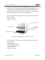
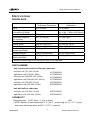

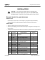
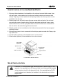

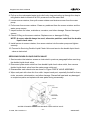

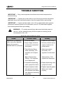
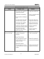
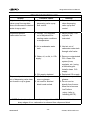
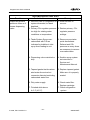
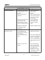
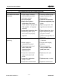
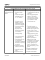
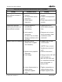
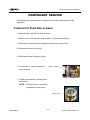
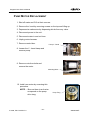
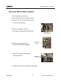
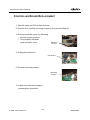
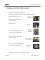
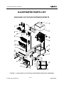
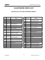
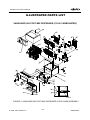
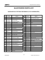
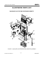
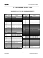
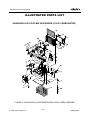

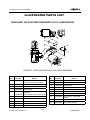
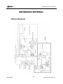
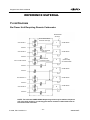
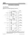
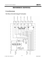
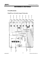
![Installation/Service Manual [ 000995 ]](http://vs1.manualzilla.com/store/data/006030040_1-6e05d98358e67eccf6d1d26ecb5fcb81-150x150.png)