1
CNR1 Net Radiometer
Revision: 1/08
C o p y r i g h t © 2 0 0 0 - 2 0 0 8
C a m p b e l l S c i e n t i f i c , I n c .
Warranty and Assistance
The CNR1 NET RADIOMETER is warranted by CAMPBELL
SCIENTIFIC, INC. to be free from defects in materials and workmanship
under normal use and service for twelve (12) months from date of shipment
unless specified otherwise. Batteries have no warranty. CAMPBELL
SCIENTIFIC, INC.'s obligation under this warranty is limited to repairing or
replacing (at CAMPBELL SCIENTIFIC, INC.'s option) defective products.
The customer shall assume all costs of removing, reinstalling, and shipping
defective products to CAMPBELL SCIENTIFIC, INC. CAMPBELL
SCIENTIFIC, INC. will return such products by surface carrier prepaid. This
warranty shall not apply to any CAMPBELL SCIENTIFIC, INC. products
which have been subjected to modification, misuse, neglect, accidents of
nature, or shipping damage. This warranty is in lieu of all other warranties,
expressed or implied, including warranties of merchantability or fitness for a
particular purpose. CAMPBELL SCIENTIFIC, INC. is not liable for special,
indirect, incidental, or consequential damages.
Products may not be returned without prior authorization. The following
contact information is for US and International customers residing in countries
served by Campbell Scientific, Inc. directly. Affiliate companies handle
repairs for customers within their territories. Please visit
www.campbellsci.com to determine which Campbell Scientific company
serves your country. To obtain a Returned Materials Authorization (RMA),
contact CAMPBELL SCIENTIFIC, INC., phone (435) 753-2342. After an
applications engineer determines the nature of the problem, an RMA number
will be issued. Please write this number clearly on the outside of the shipping
container. CAMPBELL SCIENTIFIC's shipping address is:
CAMPBELL SCIENTIFIC, INC.
RMA#_____
815 West 1800 North
Logan, Utah 84321-1784
CAMPBELL SCIENTIFIC, INC. does not accept collect calls.
CNR1 Table of Contents
PDF viewers note: These page numbers refer to the printed version of this document. Use
the Adobe Acrobat® bookmarks tab for links to specific sections.
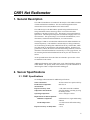
1. General Description.....................................................1
2. Sensor Specifications .................................................1
2.1 CNR1 Specifications ................................................................................1
2.2 CM3 Specifications ..................................................................................2
2.3 CG3 Specifications ...................................................................................3
3. Installation....................................................................3
4. Using the CNR1 in the Four Separate
Components Mode (4SCM)....................................5
4.1
4.2
4.3
4.4
4.5
4.6
4.7
Measuring Solar Radiation with the CM3 ................................................5
Measuring Far Infrared Radiation with the CG3 ......................................5
Measuring the CNR1’s Temperature with the Pt-100 ..............................6
Calculation of the Albedo for Solar Radiation .........................................6
Calculation of the Net Solar Radiation .....................................................6
Calculation of the Net Infrared Radiation (Net Long-Wave) ...................7
Calculation of the Net (total) Radiation....................................................7
5. Wiring............................................................................7
6. Datalogger Programming..........................................10
6.1 Calibration Factor ...................................................................................11
6.2 Example Programs..................................................................................11
6.2.1 Example 1, CR23X Program Using Differential Channels...........11
6.2.2 Example 2, CR23X Program Using Single-Ended Channels .......15
6.2.3 Example 3, CR1000 Using Differential Channels ........................17
6.2.4 Example 4, CR5000 Using Differential Channels (no 4WPB100).19
7. Calibration ..................................................................22
8. Troubleshooting ........................................................22
8.1 Testing the CM3 .....................................................................................22
8.2 Testing of the CG3 .................................................................................23
8.3 Testing the Pt-100...................................................................................23
A. CNR1 Performance and Measurements under
Different Conditions........................................... A-1
i
CNR1 Table of Contents
Figures
2-1.
3-1.
5-1.
5-2.
6-1.
The Dimensions of the CNR1................................................................. 2
CNR1 Mounting Options........................................................................ 4
CNR1 Schematic. ................................................................................... 8
Interfacing the Pt-100 Using the 4WPB100 Module.............................. 9
4WPB100 Module ................................................................................ 11
Tables
5-1. Datalogger Connections for Differential Measurement, When Using
a 4WPB100 ......................................................................................... 9
5-2. Datalogger Connections for Single-Ended Measurement, When Using
a 4WPB100 ....................................................................................... 10
5-3. CR3000 and CR5000 Connections for Differential Measurement ....... 10
A-1. Typical output signals of the CNR1 under different meteorological
conditions ........................................................................................ A-2
ii
CNR1 Net Radiometer
1. General Description
The CNR1 Net Radiometer is intended for the analysis of the radiation balance
of Solar and Far Infrared radiation. The most common application is the
measurement of Net (total) Radiation at the earth's surface.
The CNR1 design is such that both the upward-facing and the downwardfacing instruments measure the energy that is received from the whole
hemisphere (180 degrees field of view). The output is expressed in Watts per
square meter. The total spectral range that is measured is roughly from 0.3 to
50 micrometers. This spectral range covers both the Solar Radiation, 0.3 to 3
micrometers, and the Far Infrared radiation, 5 to 50 micrometers.
The design of CNR1 is such that Solar radiation and Far Infrared radiation are
measured separately. Solar radiation is measured by two CM3 pyranometers,
one for measuring incoming solar radiation from the sky, and the other, which
faces downward, for measuring the reflected Solar radiation. From these two
pyranometers, albedo, the ratio of reflected and incoming radiation, can also be
determined. Far Infrared radiation is measured by two CG3 pyrgeometers, one
for measuring the Far Infrared radiation from the sky, the other from the soil
surface.
An incorporated heater allows the CNR1 to be heated to prevent dew or frost
accumulation on the sensors.
Additional information on the CNR1 sensor can be found in the Kipp & Zonen
CNR1 Manual. The primary intent of this manual is to provide information on
interfacing the CNR1 to Campbell Scientific dataloggers.
2. Sensor Specifications
2.1 CNR1 Specifications
See the Kipp & Zonen manual for additional specifications.
Sensor sensitivities:
Pt-100 sensor temperature
measurement:
Expected accuracy of the
temperature measurement:
All four sensors have equal sensitivity
DIN class A
Operating temperature:
Requirements for data acquisition:
Radiation components:
-40 to +70 degrees Celsius
Pt-100 temperature:
Expected accuracy for daily totals:
± 2 K, under non-stable conditions
with solar heating or heating by using
the heating resistor.
4 differential or 4 single-ended analog
channels
1 excitation and 2 differential analog
channels
± 10 %
1
CNR1 Net Radiometer
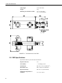
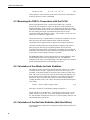
Cable length:
Weight:
Mounting arm attached to CNR1:
15 m (each cable)
4 kg
14.5” (37 cm) long
5/8” (1.6 cm) diameter
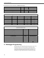
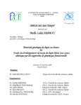
FIGURE 2-1. The Dimensions of the CNR1
2.2 CM3 Specifications
Specifications that are part of the ISO classification:
2
Response time 95%:
18 s
Non-stability:
< 1% change per year
Non-linearity:
Max. dev. 2.5% (0-1000 W m-2)
Directional error:
Max. 25 W m-2 at 1000 W m-2
Spectral selectivity:
Max. dev. 5% (350-1500 nm)
Temperature dependence of
sensitivity:
6% (-10 to +40oC)
CNR1 Net Radiometer
Tilt response:
Max. dev. 2%
Overall ISO classification:
second class
Sensitivity:
10 - 35 µV/(W m-2)
Impedance:
125 Ohm nominal
Operating temperature:
-40°C to +80°C
Spectral range:
305-2800 nm (50% points)
Expected signal range for
atmospheric application:
0 - 15 mV typical
Expected accuracy for daily sums:
± 10%
Window heating offset:
Max. 25 W m-2 at 1000 W m-2 normal
incidence solar radiation
2.3 CG3 Specifications
Response time 95%:
18 s
Non-stability:
< 1% change per year
Non-linearity:
Max. dev. 2.5% (0-1000 W m-2)
Temperature dependence of
sensitivity:
6% (-10°C to +40°C)
Tilt response:
Max. 3% when facing downwards
Field of view:
150 degrees
Sensitivity:
5 - 35 µV/(W m-2)
Impedance:
125 Ohm nominal
Operating temperature:
-40°C to +80°C
Temperature range for specified
behavior:
-10°C to +40°C
Measurement range:
-250 to +250 W m-2
Spectral range:
5 to 50 µm
Expected signal range for
atmospheric application:
-4 to 4 mV
Expected accuracy for daily sums:
± 10%
3. Installation
For measurement of the Net Radiation, it is most important that the instrument
is located in a place that is representative of the entire region that one wishes to
study.
When installed on a mast, the preferred orientation should be such that no
shadow is cast on the Net Radiometer at any time during the day. In the
3
CNR1 Net Radiometer
Northern Hemisphere this implies that the Net Radiometer should be mounted
south of the mast.
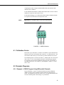
It is suggested that the CNR1 is mounted at a height of at least 1.5 meters
above the surface to avoid shading effects of the instruments on the soil and to
promote spatial averaging of the measurement. If the instrument is H meters
above the surface, 99% of the input of the lower sensors comes from a circular
area with a radius of 10 H. Shadows or surface disturbances with radius
< 0.1 H will affect the measurement by less than 1%.
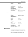
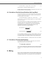
It is recommended that the CNR1 be mounted to a separate vertical pipe at
least 25’ from any other mounting structures. PN 14264 mounting bracket is
used to mount the CNR1 directly to a vertical pipe, or to a UT018 Tower
Mounting Bracket and Crossarm. Mount the sensor as follows:
NOTE
1.
Attach PN 14264 mounting bracket to the vertical mounting pipe or
UT018 crossarm using the hardware provided.
2.
Insert the CNR1 mounting arm of the sensor into the 14264 mounting
block. Tighten the four set screws just enough to secure the mounting
arm position, but loose enough to allow the arm to be rotated.
Do not attempt to rotate the instrument using the sensor heads or
you may damage the sensors; use the mounting arm only.
3.
Loosen the vertical adjustment screws on the back of the 14264 mounting
bracket. Adjust the sensor mounting arm horizontally and vertically until
the bubble level on the sensor head shows level. Tighten the adjustment
screws to secure the position.
FIGURE 3-1. CNR1 Mounting Options
For installation in buildings or in solar energy applications, one will often have
to mount the CNR1 parallel to the surface that is being studied. This may be in
a tilted or a vertical position. The sensitivity of the radiometers will be
affected, but only in a minor way. This is specified as the so-called tilt effect.
From the specifications one can see that the tilt effect (this is a change in
sensitivity) remains within 3 %.
4
CNR1 Net Radiometer
4. Using the CNR1 in the Four Separate Components
Mode (4SCM)
In the 4SCM configuration (measuring two Solar Radiation signals, two Far
Infrared signals and, for calculation purposes, one Pt-100 signal), all signals are
measured separately. Calculation of Net-Radiation and albedo can be done by
the datalogger, or later by the computer from the radiation and temperature
data.
The two CM3s will measure the solar radiation, both incoming and reflected.
The two CG3s will measure the Far Infrared radiation. For proper analysis of
the CG3 measurement results, they must be temperature corrected using the
temperature measurement performed by the Pt-100.
The following paragraphs describe how one should treat the instrument, and
how different parameters like net Solar radiation, net Far Infrared radiation,
soil temperature, sky temperature, and Net (total) radiation can be calculated.
4.1 Measuring Solar Radiation with the CM3
Measuring with the upward-facing CM3 the so-called global (solar) radiation is
measured. The downward-facing CM3 measures the reflected solar radiation.
When calculating the Net radiation, the Reflected radiation must be subtracted
from the global radiation. See Section 4.5.
The CM3 pyranometer generates a mV signal that is simply proportional to the
incoming Solar radiation. The conversion factor between voltage, V, and
Watts per square meter of solar irradiance E, is the so-called calibration
constant C (or sensitivity).
For the CM3
E = V/C
(4.1)
4.2 Measuring Far Infrared Radiation with the CG3
The downward-facing CG3 measures the Far Infrared radiation that is emitted
by the ground. The upward-facing CG3 measures the Far Infrared radiation
from the sky. As the sky is typically colder than the instrument, one can expect
negative voltage signals from the upward-facing CG3. For this measurement,
the Pt-100 output is required. The Equation 4.2 is used to calculate the Far
Infrared irradiance of the sky and of the ground.
When using the CG3 pyrgeometer, one should realize that the signal that is
generated by the CG3 represents the exchange of Far Infrared (thermal)
radiation between the CG3 and the object that it is facing. This implies that the
CG3 will generate a positive voltage output, V, when it faces an object that is
hotter than its own sensor housing, and that it will give a negative voltage
signal when it faces an object that is colder. This means that for estimating the
Far Infrared radiation that is generated by the object that is faced by the
pyrgeometer, usually the sky or the soil, one will have to take the pyrgeometer
temperature, T, into account. This is why a Pt-100 is incorporated in the
CNR1's body. (This body is in very good thermal contact with the CG3 and
has the same temperature as the CG3 sensor surface.) The calculation of the
Far Infrared irradiance, E, is done according to the following equation:
5
CNR1 Net Radiometer
For the CG3 only
E = V/C + 5.67 ⋅ 10-8 ∗ T4
(4.2)
In this equation C is the sensitivity of the sensor. Please bear in mind that T is
in Kelvin, and not in Celsius or Fahrenheit.
4.3 Measuring the CNR1’s Temperature with the Pt-100
The Pt-100 temperature sensor is located in the CNR1 body. It will not
measure the exact temperature of the CG3 unless the whole instrument is in
thermal equilibrium. Errors, however, are minimized in the design by making
solid metal connections between the sensors and the temperature sensor. When
the sun is shining, the largest expected deviation between real sensor
temperature and Pt-100 reading is 2 degrees. This results in a worst-case error
for the CG3 of 10 Watts per square meter.
The Pt-100 will not give a good indication of ambient air temperature; at 1000
Watts per square meter Solar radiation, and no wind, the instrument
temperature will rise approximately 12 degrees above ambient temperature.
The offsets of both pyranometers and pyrgeometers might be larger than 10
Watts per square meter if large temperature gradients are forced on the
instrument (larger than 5 K/hr). This happens, for example, when rain hits the
instrument. The occurrence of this can be detected using the Pt-100 readout. It
can be used as a tool for quality assurance of your data.
The 4WPB100 module is used to interface the Pt-100 to the datalogger, and is
included with the CNR1 sensor purchased from CSI. The 4WPB100
configures the Pt-100 as a 4-wire half bridge circuit that requires one excitation
and two differential channels on the datalogger (Section 5).
4.4 Calculation of the Albedo for Solar Radiation
The albedo is the ratio of incoming and reflected Solar radiation. It is a figure
somewhere between 0 and 1. Typical values are 0.9 for snow, and 0.3 for
grassland. To determine albedo, the measured values of the two CM3s can be
used. The CG3s are not involved, as they do not measure Solar radiation. Do
not use measured values when solar elevation is lower than 10 degrees above
the horizon. Errors in measurement at these elevations are likely and thus
yielding unreliable results. This is due to deviations in the directional response
of the CM3s.
Albedo = (E lower CM3) / (E upper CM3)
(4.3)
In the above formula, E is calculated according to Equation 4.1.
Albedo will always be smaller than 1. Checking this can be used as a tool for
quality assurance of your data. If you know the approximate albedo at your
site, the calculation of albedo can also serve as a tool for quality control of your
measured data at this specific site.
4.5 Calculation of the Net Solar Radiation (Net Short-Wave)
Net Solar radiation is equal to the incoming solar radiation minus the reflected
solar radiation.
6
CNR1 Net Radiometer
Net Solar radiation = (E upper CM3) - (E lower CM3)
(4.4)
In this formula E is calculated according to Equation 4.1.
Net Solar radiation will always be positive. Checking this can be used as a tool
for quality assurance of your measured data.
4.6 Calculation of the Net Infrared Radiation (Net Long-Wave)
Net Far Infrared radiation is, like Net Solar radiation, the part that contributes
to heating or cooling of the earth's surface. In practice, most of the time Net
Far Infrared radiation will be negative.
Net Far Infrared radiation = (E upper CG3) - (E lower CG3)
(4.5)
In this formula E is calculated according to Equation 4.2. From this equation
the term with T cancels.
The E measured with the CG3 actually represents the irradiance of the sky (for
the upward- facing CG3) or the ground (for the downward-facing CG3).
Assuming that these two, ground and sky, behave like perfect blackbodies
(actually this is only in theory), one can calculate an effective "Sky
temperature" and an effective "Ground temperature".
⎡ E upper CG3 ⎤
Sky temperature = ⎢
⎥
⎣ 5.67 ⋅ 10 −8 ⎦
1/ 4
⎡ E lower CG3 ⎤
Ground Temperature = ⎢
⎥
⎣ 5.67 ⋅ 10 −8 ⎦
(4.6)
1/ 4
(4.7)
As a rule of thumb, for ambient temperatures of about 20 degrees Celsius, one
can say that one degree of temperature difference between two objects results
in a 5 Watts per square meter exchange of radiative energy (infinite objects):
1 degree of temperature difference = 5 Watts per square meter (rule of thumb)
4.7 Calculation of the Net (total) Radiation
In the 4 Separate Components Mode, Net radiation, NR, can be calculated
using the individual sensor measurement results:
NR = (E upper CM3) + (E upper CG3) (E lower CM3) - (E lower CG3)
(4.8)
Where E is the irradiance that is calculated for the CM3 according to Equation
4.1, for the CG3 according to Equation 4.2, the terms with T cancel from this
equation.
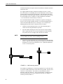
5. Wiring
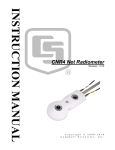
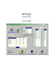
Figure 5-1 shows the CNR1 schematic with the four radiation outputs, Pt-100
temperature sensor, and the heater. The use of the heater is described in detail
in the Kipp & Zonen manual. All wiring schemes shown in this manual will
7
CNR1 Net Radiometer
show wiring for both CNR1 and 4WPB100 modules. Wiring diagrams and
Tables 5-1 and 5-2 are applicable only if you bought the CNR1 Net
Radiometer from Campbell Scientific, Inc.
Use of the CNR1 Net Radiometer, which you bought outside of Campbell
Scientific, is possible only on the CR3000 and CR5000 dataloggers. The
PT-100 can connect directly to the CR3000 and CR5000 because they have
current excitation inputs. Table 5-3 and Program Example 6.2.4 show wiring
and programming on the CR5000 datalogger without the 4WPB module.
All other CSI dataloggers require the 4WPB100 module to interface the
PT-100 to the datalogger.
FIGURE 5-1. CNR1 Schematic
8
CNR1 Net Radiometer
DATALOGGER
EX1
4WPB100
10K
5H
H
100
CNR1
5L
L
Red
G
6H
Yellow
PT-100
6L
Green
Blue
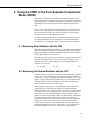
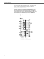
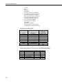
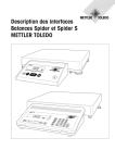
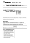
FIGURE 5-2. Interfacing the Pt-100 Using the 4WPB100 Module
The four radiation outputs can be measured using Differential or Single-Ended
inputs on the datalogger. A differential voltage measurement (Instruction 2) is
recommended because it has better noise rejection than a single-ended
measurement. When differential inputs are used, jumper the low side of the
to keep the signal in common mode range.
input to AG or
TABLE 5-1. Datalogger Connections for Differential Measurement, When Using a 4WPB100
Function
CM3 Up Signal
CM3 Up Reference
CM3 Down Signal
CM3 Down Reference
CG3 Up Signal
CG3 Up Reference
CG3 Down Signal
CG3 Down Reference
Shield
Color
Red
*Blue
White
*Black
Grey or
†Orange
*Yellow
Brown
*Green
Shield
CR10X,CR510
Differential Input (H)
Differential Input (L)
Differential Input (H)
Differential Input (L)
Differential Input (H)
CR23X
Differential Input (H)
Differential Input (L)
Differential Input (H)
Differential Input (L)
Differential Input (H)
21X/CR7
Differential Input (H)
Differential Input (L)
Differential Input (H)
Differential Input (L)
Differential Input (H)
Differential Input (L)
Differential Input (H)
Differential Input (L)
G
Differential Input (L)
Differential Input (H)
Differential Input (L)
Differential Input (L)
Differential Input (H)
Differential Input (L)
*Jumper to AG or
with user supplied wire.
†Cables extended > 48’ have an orange wire.
9
CNR1 Net Radiometer
Pt-100 Temperature Sensor Connections to 4WPB100 and Datalogger
Function
Color
Black
Pt-100 Excitation +
Pt-100 Excitation Pt-100 Signal +
Pt-100 Signal –
Red
Blue
Yellow
Green
4WPB100
Wire
H
L
G
Datalogger
Excitation
Differential Input (H)
Differential Input (L)
(AG CR10X/CR510)
Differential Input (H)
Differential Input (L)
TABLE 5-2. Datalogger Connections for Single-Ended Measurement, When Using a 4WPB100
Function
CM3 Up Signal
CM3 Up Reference
CM3 Down Signal
CM3 Down Reference
CG3 Up Signal
CG3 Up Reference
CG3 Down Signal
CG3 Down Reference
Shield
Color
Red
Blue
White
Black
Grey or Orange
Yellow
Brown
Green
Shield
CR10X,CR510
Single-Ended Input
AG
Single-Ended Input
AG
Single-Ended Input
AG
Single-Ended Input
AG
G
CR23X
Single-Ended Input
21X/CR7
Single-Ended Input
Single-Ended Input
Single-Ended Input
Single-Ended Input
Single-Ended Input
Single-Ended Input
Single-Ended Input
TABLE 5-3. CR3000 and CR5000 Connections
for Differential Measurement
Function
CM3 Up Signal
CM3 Up Reference
CM3 Down Signal
CM3 Down Reference
CG3 Up Signal
CG3 Up Reference
CG3 Down Signal
CG3 Down Reference
PT-100 Signal +
PT-100 Signal PT-100 Current Excitation +
PT-100 Current Excitation Shield
Color
Red
Blue
White
Black
Grey or Orange
Yellow
Brown
Green
Yellow
Green
Red
Blue
Clear
CR3000/CR5000
Differential Input (H)
Differential Input (L)
Differential Input (H)
Differential Input (L)
Differential Input (H)
Differential Input (L)
Differential Input (H)
Differential Input (L)
Differential Input (H)
Differential Input (L)
Current Excitation IX
Current Excitation IXR
6. Datalogger Programming
The CNR1 outputs four voltages that typically range from 0 to 15 mV for the
CM3 sensors, and ± 5 mV for the CG3 sensors. A differential voltage
measurement (Instruction 2) is recommended because it has better noise
rejection than a single-ended measurement. If differential channels are not
available, single-ended measurements (Instruction 1) can be used. The
acceptability of a single-ended measurement can be determined by simply
10
CNR1 Net Radiometer
comparing the results of single-ended and differential measurements made
under the same conditions.
For the CR3000 and CR5000, one differential channel and a current excitation
channel are required to measure the PT-100.
For the other dataloggers, two differential channels and the 4WPB100 module
are required to measure the Pt-100 temperature sensor.
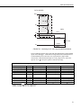
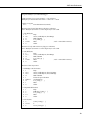
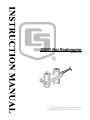
NOTE
The 4WPB100 is included with the CNR1 sensor purchased from
CSI.
FIGURE 6-1. 4WPB100 Module
6.1 Calibration Factor
Each CNR1 is provided with a ‘Certificate of Calibration’ by the manufacturer
that shows the sensor serial number and ‘sensitivity’, or calibration factor. The
serial number and sensitivity are also shown on a label attached to the sensor.
The calibration factor is in units of uV/(W m-2), which needs to be converted to
units of (W m-2)/mV for the multiplier parameter in the datalogger program.
To convert the units, divide the calibration factor into 1000. For example, if
the calibration factor is 7.30 uV/(W m-2), the multiplier is 1000/7.3 = 136.99
(W m-2)/mV.
6.2 Example Programs
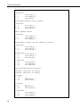
6.2.1 Example 1, CR23X Program Using Differential Channels
Program Example 1 requires six differential channels and the 4WPB100
module to measure the four radiation outputs and the Pt-100 temperature
sensor. The program measures the sensors every 2 seconds and calculates and
stores the following data to final storage every 60 minutes:
11
CNR1 Net Radiometer
Array ID
Year
Julian Day
Hour/Minute
Avg CM3 Up (shortwave radiation)
Avg CM3 Down (shortwave radiation)
Avg CG3 Up (longwave radiation)
Avg CG3 Down (longwave radiation)
Avg CNR1 temperature (degrees C)
Avg CNR1 temperature (degrees K)
Avg Net shortwave radiation
Avg Net longwave radiation
Avg Albedo
Avg Total Net radiation
Avg temperature corrected CG3 Up
Avg temperature corrected CG3 Down
Wiring for Program Example 1
Color
Red
Blue
White
Black
Grey or Orange
Yellow
Brown
Green
Shield
Function
CM3 Up Signal
CM3 Up Reference
CM3 Down Signal
CM3 Down Reference
CG3 Up Signal
CG3 Up Reference
CG3 Down Signal
CG3 Down Reference
Shield
Example CR23X
Program
Channels Used
1H
1L
2H
2L
3H
3L
4H
4L
Pt-100 Temperature Sensor Connections to 4WPB100 and Datalogger
12
Color
Black
Function
Red
Blue
Yellow
Green
Pt-100 Excitation +
Pt-100 Excitation Pt-100 Signal +
Pt-100 Signal -
4WPB100
Wire
H
L
G
CR23X
EX1
5H
5L
6H
6L
CNR1 Net Radiometer
;{CR23X}
;Program Example 1 for CR23X datalogger
;
;CNR1 sensitivity for program example = 7.30 uV/W/m^2
;Multiplier for measurement instructions = 1000/7.30 = 136.99
;
;*Table 1 Program
01: 2
Execution Interval (seconds)
;Measure CM3 Up and CM3 Down (shortwave radiation)
;Note: Multiplier (Parameter 5) will be different for each CNR1
1: Volt (Diff) (P2)
1: 2
2: 22+
3: 1*
4: 1*
5: 136.99
6: 0
Reps
50 mV, 60 Hz Reject, Slow Range
DIFF Channel
Loc [ CM3_up ]
Mult
; mult = 1000/CNR1 sensitivity
Offset
;Measure CG3 Up and CG3 Down (longwave radiation)
;Note: Multiplier (Parameter 5) will be different for each CNR1
2: Volt (Diff) (P2)
1: 2
2: 21++
3: 3*
4: 3*
5: 136.99
6: 0
Reps
10 mV, 60 Hz Reject, Slow Range
DIFF Channel
Loc [ CG3_up ]
Mult
; mult = 1000/CNR1 sensitivity
Offset
;Measure CNR1 temperature
3: Full Bridge w/mv Excit (P9)
1: 1
Reps
2: 22**
50 mV, 60 Hz Reject, Slow, Ex Range
3: 22**
50 mV, 60 Hz Reject, Slow, Br Range
4: 5*
DIFF Channel
5: 1
Excite all reps w/Exchan 1
6: 4200***
mV Excitation
7: 5*
Loc [ Temp_C ]
8: 1
Mult
9: 0
Offset
4: Temperature RTD (P16)
1: 1
Reps
2: 5
R/R0 Loc [ Temp_C
3: 5
Loc [ Temp_C ]
4: 1.0
Mult
5: 0
Offset
5: Z=X+F (P34)
1: 5
2: 273.18
3: 6
]
X Loc [ Temp_C ]
F
Z Loc [ Temp_K ]
13
CNR1 Net Radiometer
;Net CM3 shortwave radiation = CM3 Up - CM3 Down
6: Z=X-Y (P35)
1: 1
2: 2
3: 7
X Loc [ CM3_up ]
Y Loc [ CM3_dn ]
Z Loc [ Net_Rs ]
;Net CG3 longwave radiation = CG3 Up - CG3 Down
7: Z=X-Y (P35)
1: 3
2: 4
3: 8
X Loc [ CG3_up ]
Y Loc [ CG3_dn ]
Z Loc [ Net_Rl ]
;Albedo = CM3 Down / CM3 Up
8: Z=X/Y (P38)
1: 2
2: 1
3: 9
X Loc [ CM3_dn ]
Y Loc [ CM3_up ]
Z Loc [ Albedo ]
;Net total radiation = (CM3 Up + CG3 Up) - (CM3 Down + CG3 Down)
9: Z=X+Y (P33)
1: 1
2: 3
3: 23
X Loc [ CM3_up ]
Y Loc [ CG3_up ]
Z Loc [ Up_total ]
10: Z=X+Y (P33)
1: 2
X Loc [ CM3_dn ]
2: 4
Y Loc [ CG3_dn ]
3: 24
Z Loc [ Dn_total ]
11: Z=X-Y (P35)
1: 23
X Loc [ Up_total ]
2: 24
Y Loc [ Dn_total ]
3: 10
Z Loc [ Net_total ]
;Correct CG3 Up and CG3 Down for temperature
; CG3_upCor = CG3_up+5.67 ⋅ 10-8 ∗ Temp_K4
; CG3_dnCor = CG3_dn+5.67 ⋅ 10-8 ∗ Temp_K4
12: Z=F (P30)
1: 5.67
2: -8
3: 25
F
Exponent of 10
Z Loc [ scratch_1 ]
13: Z=F (P30)
1: 4
2: 0
3: 26
F
Exponent of 10
Z Loc [ scratch_2 ]
14: Z=X^Y (P47)
1: 6
X Loc [ Temp_K ]
2: 26
Y Loc [ scratch_2 ]
3: 27
Z Loc [ scratch_3 ]
14
CNR1 Net Radiometer
15: Z=X*Y (P36)
1: 25
X Loc [ scratch_1 ]
2: 27
Y Loc [ scratch_3 ]
3: 28
Z Loc [ scratch_4 ]
16: Z=X+Y (P33)
1: 3
X Loc [ CG3_up ]
2: 28
Y Loc [ scratch_4 ]
3: 11
Z Loc [ CG3_upCor ]
17: Z=X+Y (P33)
1: 4
X Loc [ CG3_dn ]
2: 28
Y Loc [ scratch_4 ]
3: 12
Z Loc [ CG3_dnCor ]
;
;Output data to final storage every 60 minutes
18: If time is (P92)
1: 0
Minutes (Seconds --) into a
2: 60
Interval (same units as above)
3: 10
Set Output Flag High (Flag 0)
19: Real Time (P77)
1: 0220
Day,Hour/Minute (midnight = 2400)
20: Average (P71)
1: 12
Reps
2: 1
Loc [ CM3_dn
]
* Proper entries will vary with program and input channel usage.
** 25 mV range for CR10X, 50 mV for 21X and CR7
*** 4200 mV for 21X and CR7, 2100 mV for CR10X
+ 25 mV range for CR10X, 50 mV for 21X and CR7
++ 7.5 mV range for CR10X, 5 mV for 21X and CR7
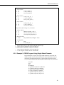
6.2.2 Example 2, CR23X Program Using Single-Ended Channels
Program Example 2 requires four single-ended channels to measure the four
radiation outputs, and two differential channels and the 4WPB100 module to
measure the Pt-100 temperature sensor. The program measures the sensors
every 2 seconds and stores the following data to final storage every 60 minutes:
Array ID
Year
Day
Hour/Minute
Avg CM3 down (shortwave radiation)
Avg CM3 up (shortwave radiation)
Avg CG3 down (longwave radiation)
Avg CG3 up (longwave radiation)
Avg CNR1 temperature (degrees C)
Avg CNR1 temperature (degrees K)
15
CNR1 Net Radiometer
Wiring for Program Example 2
Color
Function
Red
Blue
White
Black
Grey or Orange
Yellow
Brown
Green
Shield
CM3 Up Signal
CM3 Up Reference
CM3 Down Signal
CM3 Down Reference
CG3 Up Signal
CG3 Up Reference
CG3 Down Signal
CG3 Down Reference
Shield
Example CR23X Program
Channels Used
SE1
SE2
SE3
SE4
Pt-100 Temperature Sensor Connections to 4WPB100 and Datalogger
Color
Function
Red
Blue
Yellow
Green
Pt-100 Excitation +
Pt-100 Excitation Pt-100 Signal +
Pt-100 Signal -
4WPB100
H
L
G
;{CR23X}
;
;CNR1 sensitivity for program example = 7.30 uV/W/m^2
;Multiplier for measurement instructions = 1000/7.3 = 136.99
*Table 1 Program
01: 2
Execution Interval (seconds)
;Measure CM3 Up and CM3 Down (shortwave radiation)
;Note: Multiplier (Parameter 6) will be different for each CNR1
1: Volt (SE) (P1)
1: 2
2: 22
3: 1
4: 1
5: 136.99
6: 0
Reps
50 mV, 60 Hz Reject, Slow Range
SE Channel
Loc [ CM3_up ]
Mult ; mult = 1000/CNR1 sensitivity
Offset
;Measure CG3 Up and CG3 Down (longwave radiation)
;Note: Multiplier (Parameter 6) will be different for each CNR1
2: Volt (SE) (P1)
1: 2
2: 21
3: 3
4: 3
5: 136.99
6: 0
16
Reps
10 mV, 60 Hz Reject, Slow Range
SE Channel
Loc [ CG3_up ]
Mult ; mult = 1000/CNR1 sensitivity
Offset
CR23X
5H
5L
6H
6L
CNR1 Net Radiometer
;Measure CNR1 temperature
3: Full Bridge w/mv Excit (P9)
1: 1
Reps
2: 22
50 mV, 60 Hz Reject, Slow, Ex Range
3: 22
50 mV, 60 Hz Reject, Slow, Br Range
4: 5
DIFF Channel
5: 1
Excite all reps w/Exchan 1
6: 4200
mV Excitation
7: 5
Loc [ Temp_C ]
8: 1
Mult
9: 0
Offset
4: Temperature RTD (P16)
1: 1
Reps
2: 5
R/R0 Loc [ Temp_C
3: 5
Loc [ Temp_C ]
4: 1.0
Mult
5: 0
Offset
5: Z=X+F (P34)
1: 5
2: 273.18
3: 6
]
X Loc [ Temp_C ]
F
Z Loc [ Temp_K ]
;Output data to final storage every 60 minutes
6: If time is (P92)
1: 0
Minutes (Seconds --) into a
2: 60
Interval (same units as above)
3: 10
Set Output Flag High (Flag 0)
7: Real Time (P77)
1: 0220
Day,Hour/Minute (midnight = 2400)
8: Average (P71)
1: 6
Reps
2: 1
Loc [ CM3_up
]
Copy range code options from example 1 here:
* Proper entries….
* Proper entries will vary with program and input channel usage.
** 25 mV range for CR10X, 50 mV for 21X and CR7
*** 4200 mV for 21X and CR7, 2100 mV for CR10X
+ 25 mV range for CR10X, 50 mV for 21X and CR7
++ 7.5 mV range for CR10X, 5 mV for 21X and CR7
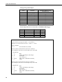
6.2.3 Example 3, CR1000 Using Differential Channels
Program Example 3 requires six differential channels and the 4WPB100
module to measure the four radiation outputs and the Pt-100 temperature
sensor. The program measures the sensors every 2 seconds and calculates and
stores the following data to final storage every 60 minutes:
17
CNR1 Net Radiometer
Year
Julian Day
Hour/Minute
Avg CM3 Up (shortwave radiation)
Avg CM3 Down (shortwave radiation)
Avg CG3 Up (longwave radiation)
Avg CG3 Down (longwave radiation)
Avg CNR1 temperature (degrees C)
Avg CNR1 temperature (degrees K)
Avg Net shortwave radiation
Avg Net longwave radiation
Avg Albedo
Avg Total Net radiation
Avg temperature corrected CG3 Up
Avg temperature corrected CG3 Down
'CR1000
'Declare Variables and Units
Public Batt_Volt
Public CM3Up
Public CM3Dn
Public CG3Up
Public CG3Dn
Public CNR1TC
Public CNR1TK
Public NetRs
Public NetRl
Public Albedo
Public UpTot
Public DnTot
Public NetTot
Public CG3UpCo
Public CG3DnCo
Units Batt_Volt=Volts
Units CM3Up=W/meter²
Units CM3Dn=W/meter²
Units CG3Up=W/meter²
Units CG3Dn=W/meter²
Units CNR1TC=Deg C
Units CNR1TK=K
Units NetRs=W/meter²
Units NetRl=W/meter²
Units Albedo=W/meter²
Units UpTot=W/meter²
Units DnTot=W/meter²
Units NetTot=W/meter²
Units CG3UpCo=W/meter²
Units CG3DnCo=W/meter²
18
CNR1 Net Radiometer
'Define Data Tables
DataTable(Table1,True,-1)
DataInterval(0,60,Min,10)
Average(1,CM3Up,FP2,False)
Average(1,CM3Dn,FP2,False)
Average(1,CG3Up,FP2,False)
Average(1,CG3Dn,FP2,False)
Average(1,CNR1TC,FP2,False)
Average(1,CNR1TK,FP2,False)
Average(1,NetRs,FP2,False)
Average(1,NetRl,FP2,False)
Average(1,Albedo,FP2,False)
Average(1,UpTot,FP2,False)
Average(1,DnTot,FP2,False)
Average(1,NetTot,FP2,False)
Average(1,CG3UpCo,FP2,False)
Average(1,CG3DnCo,FP2,False)
EndTable
'Main Program
BeginProg
Scan(2,Sec,1,0)
'Default Datalogger Battery Voltage measurement Batt_Volt:
Battery(Batt_Volt)
'CNR1 Net Radiometer measurements CM3Up, CM3Dn, CG3Up, CG3Dn, CNR1TC, CNR1TK,
'NetRs, NetRl, Albedo, UpTot, DnTot, NetTot, CG3UpCo, and CG3DnCo:
* VoltDiff(CM3Up,1,mV25,1,True,0,_60Hz,100.0,0)
* VoltDiff(CM3Dn,1,mV25,2,True,0,_60Hz,100.0,0)
* VoltDiff(CG3Up,1,mV7_5,3,True,0,_60Hz,100.0,0)
* VoltDiff(CG3Dn,1,mV7_5,4,True,0,_60Hz,100.0,0)
** BrHalf4W (CNR1TC,1,mV25,mV25,5,Vx1,1,2100,True ,True ,0,250,1.0,0)
PRT(CNR1TC,1,CNR1TC,1,0)
CNR1TK=CNR1TC+273.18
NetRs=CM3Up-CM3Dn
NetRl=CG3Up-CG3Dn
Albedo=CM3Dn/CM3Up
UpTot=CM3Up+CG3Up
DnTot=CM3Dn+CG3Dn
NetTot=UpTot-DnTot
CG3UpCo=CG3Up+5.67*10^-8*CNR1TK^4
CG3DnCo=CG3Dn+5.67*10^-8*CNR1TK^4
'Call Data Tables and Store Data
CallTable(Table1)
NextScan
EndProg
* mV20 range for the CR5000
** mV50 range (both) with 4200 mV excitation for CR5000
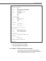
6.2.4 Example 4, CR5000 Using Differential Channels (no 4WPB100)
Program Example 4 requires five differential channels and one current
excitation channel to measure the four radiation outputs and the Pt-100
temperature sensor. The program measures the sensors every second and
calculates and stores the following data to final storage every 60 minutes:
19
CNR1 Net Radiometer
Year
Julian Day
Hour/Minute
Avg CM3 Up (shortwave radiation)
Avg CM3 Down (shortwave radiation)
Avg CG3 Up (longwave radiation)
Avg CG3 Down (longwave radiation)
Avg CNR1 temperature (degrees C)
Avg CNR1 temperature (degrees K)
Avg Net shortwave radiation
Avg Net longwave radiation
Avg Albedo
Avg Total Net radiation
Avg temperature corrected CG3 Up
Avg temperature corrected CG3 Down
'CR5000 Series Datalogger
'ANALOG INPUT
'1H
CM3 UP - downwelling shortwave radiation signal (red)
'1L
CM3 UP - downwelling shortwave radiation signal reference (blue)
'gnd
CNR1 shield (clear)
'2H
'2L
CM3 DOWN - upwelling shortwave radiation signal (white)
CM3 DOWN - upwelling shortwave radiation signal reference (black)
'3H
'3L
CG3 UP - downwelling longwave radiation signal (gray)
CG3 UP - downwelling longwave radiation signal reference (yellow)
'4H
'4L
CG3 DOWN - upwelling longwave radiation signal (brown)
CG3 DOWN - upwelling longwave radiation signal reference (green)
'6H
'6L
CNR1 Pt100 (yellow)
CNR1 Pt100 (green)
'Current Excitation
'IX1
CNR1 Pt100 (red)
'IXR
CNR1 Pt100 (blue)
'Declare Variables and Units
Public Batt_Volt
Public CM3Up
Public CM3Dn
Public CG3Up
Public CG3Dn
Public CNR1TC
Public CNR1TK
Public NetRs
Public NetRl
Public Albedo
Public UpTot
Public DnTot
Public NetTot
Public CG3UpCo
Public CG3DnCo
20
CNR1 Net Radiometer
Units Batt_Volt=Volts
Units CM3Up=W/meter²
Units CM3Dn=W/meter²
Units CG3Up=W/meter²
Units CG3Dn=W/meter²
Units CNR1TC=Deg C
Units CNR1TK=K
Units NetRs=W/meter²
Units NetRl=W/meter²
Units Albedo=W/meter²
Units UpTot=W/meter²
Units DnTot=W/meter²
Units NetTot=W/meter²
Units CG3UpCo=W/meter²
Units CG3DnCo=W/meter²
'Define Data Tables
DataTable(Table1,True,-1)
DataInterval(0,60,Min,10)
Average(1,CM3Up,FP2,False)
Average(1,CM3Dn,FP2,False)
Average(1,CG3Up,FP2,False)
Average(1,CG3Dn,FP2,False)
Average(1,CNR1TC,FP2,False)
Average(1,CNR1TK,FP2,False)
Average(1,NetRs,FP2,False)
Average(1,NetRl,FP2,False)
Average(1,Albedo,FP2,False)
Average(1,UpTot,FP2,False)
Average(1,DnTot,FP2,False)
Average(1,NetTot,FP2,False)
Average(1,CG3UpCo,FP2,False)
Average(1,CG3DnCo,FP2,False)
EndTable
'Main Program
BeginProg
Scan(1,Sec,1,0)
'Default Datalogger Battery Voltage measurement Batt_Volt:
Battery(Batt_Volt)
'CNR1 Net Radiometer measurements CM3Up, CM3Dn, CG3Up, CG3Dn, CNR1TC, CNR1TK,
'NetRs, NetRl, Albedo, UpTot, DnTot, NetTot, CG3UpCo, and CG3DnCo:
'CNR1 Sensitivity 7.30 uV/m^2
VoltDiff(CM3Up,1,mV20C,1,True,200,250,136.99,0)
VoltDiff(CM3Dn,1,mV20C,2,True,200,250,136.9,0)
VoltDiff(CG3Up,1,mV20C,3,True,200,250,136.9,0)
VoltDiff(CG3Dn,1,mV20,4,True,200,250,136.9,0)
Resistance (CNR1TC,1,mV200,6,Ix1,1,1675,True ,True,200,250,1.0,0)
'Formulate the ratio Rs/R0
CNR1TC=CNR1TC/100
PRT(CNR1TC,1,CNR1TC,1,273.15)
'Compute Net short-wave radiation, Net long-wave radiation, Albedo and Net Radiation
CNR1TC=CNR1TK-273.15
NetRs=CM3Up-CM3Dn
NetRl=CG3Up-CG3Dn
21
CNR1 Net Radiometer
EndProg
Albedo=CM3Dn/CM3Up
UpTot=CM3Up+CG3Up
DnTot=CM3Dn+CG3Dn
NetTot=UpTot-DnTot
CG3UpCo=CG3Up+5.67*10^-8*CNR1TK^4
CG3DnCo=CG3Dn+5.67*10^-8*CNR1TK^4
'Call Data Tables and Store Data
CallTable(Table1)
NextScan
7. Calibration
The CNR1 should be recalibrated every two years, or as an alternative, by
letting a higher standard run parallel to it over a two-day period and then
comparing the results. For comparison of pyranometers, one should use a clear
day. For comparison of pyrgeometers, one should compare nighttime results.
Deviations of more than 6% can be used to correct the calibration factors.
8. Troubleshooting
If there is no clue as to what may be the problem, start performing the
following "upside-down test", which is a rough test for a first diagnosis. It can
be performed both outdoors and indoors. Indoors, a lamp can be used as a
source for both Solar and Far Infrared radiation. Outdoors one should
preferably work with a solar elevation of more than 45 degrees (45 degrees
above horizon) and of course under stable conditions (no large changes in solar
irradiance, preferably cloudless).
1.
Measure the radiation outputs in the normal position. Record the
measured values when the signals have stabilized, i.e. after about three
minutes.
2.
Rotate the instrument 180 degrees, so that the upper and the lower sensors
are now in the reverse orientation as to the previous position.
3.
Measure the radiation outputs once more. Record the measured values
when the radiometers have stabilized.
4.
Since of the all sensors are trimmed, the values in the rotated position
should be equal in magnitude, only differing in sign. In a rough test like
this, deviations of +/- 10 % can be tolerated. If deviations greater than
this are encountered, the following tests might help.
8.1 Testing the CM3
As a first test we recommend that one check the sensor impedance. It should
have a nominal value as indicated in the specifications. Zero, or infinite
resistance, indicates a failure in hardware connection.
Before starting the second test measurement, let the CM3 rest for at least five
minutes to let it regain its thermal equilibrium. For testing, set a voltmeter to
its most sensitive range setting. Darken the sensor. The signal should read
22
CNR1 Net Radiometer
zero. Bear in mind that the response takes about one minute. Small deviations
from zero are possible; this is caused by thermal effects like touching the
pyranometer with your hand. The latter effect can be demonstrated by
deliberately heating the CM3 with your hand. Another cause might be the zero
offset of the amplifier. When this is the case, the same offset will also be
present when the amplifier is short-circuited with a 200 Ohm resistor. This is
an amplifier error. This amplifier error should not be larger than 5 Watts per
square meter. If the amplifier error is within specifications, proceed with the
third test.
In the third test the sensor should be exposed to light. The signal should be a
positive reading. Set the voltmeter range in such a way that the expected fullscale output of the pyranometer is within the full-scale input range of the
voltmeter. The range can be estimated on theoretical considerations. (When
the maximum expected radiation is 1500 Watts per square meter, which is
roughly equal to normal outdoor daylight conditions, and the sensitivity of the
pyranometer is 15 mV per Watt per square meter, the expected output range of
the pyranometer is 1500 times 15 which is equal to 22500 mV, or 0.0225
Volts). One can calculate the radiation intensity by dividing the pyranometer
output (0.0225 volts) by the calibration factor (0.000015 volt per watt per
square meter). Still no faults found? Your pyranometer is probably doing fine.
8.2 Testing of the CG3
It is assumed that the amplifier circuit is the same as the one used for the CM3,
and that its zero offset is no more than a few watts per square meter, let us say
5 Watts per square meter just as an example (see second test in 7.1).
The pyrgeometer, the mounting plate, and ambient air should be at the same
temperature as much as possible. Let the CG3 rest for at least five minutes to
regain its thermal equilibrium. Set the voltmeter to its most sensitive range.
To test if the CG3 is working properly, we suggest putting your hand in front
of the CG3. The thermal radiation will cause CG3 to generate a positive
voltage when the hand's surface temperature is higher than the pyrgeometer
temperature. The CG3 will generate a negative voltage if the hand is colder.
The signal is proportional to the temperature difference (see the rule of thumb
of Section 4.5). The radiation that is emitted by the hand can be calculated by
dividing the pyrgeometer output by the calibration factor, and subsequently
correcting for the temperature, according to Equation 4.2. Still no faults
found? Your pyrgeometer is probably doing fine.
8.3 Testing the Pt-100
Using a meter which measures resistance, check the operation of the Pt-100. If
connected properly, the resistance of two opposite wires of the Pt-100 should
measure about 100 ohms (this includes the cable resistance for the standard 10meter cable). The cable resistance should measure about 0.1 ohms per meter
cable.
23
CNR1 Net Radiometer
This is a blank page.
24
Appendix A. CNR1 Performance and
Measurements under Different
Conditions
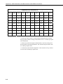
Below, Table A-1, shows an indication of what one might typically expect to
measure under different meteorological conditions.
The first parameter is day and night. At night, the Solar radiation is zero. The
second column indicates if it is cloudy or clear. A cloud acts like a blanket,
absorbing part of the Solar radiation, and keeping Net Far Infrared radiation
close to zero. The third parameter is ambient temperature. This is included to
show that the "sky temperature" (column nine) tracks the ambient temperature.
Under cloudy conditions this is logical; cloud bases will be colder than the
ambient temperature at instrument level, the temperature difference depends
roughly on cloud altitude.
Under clear sky conditions it is less obvious that sky temperature "adjusts" to
the ambient temperature. This can roughly be attributed to the water vapor in
the air, which is a major contributor to the Far Infrared radiation.
It is assumed that when ambient temperature varies, the Net Far Infrared
radiation remains roughly the same, independent of ambient temperature. The
resulting measured values of the CG3's and CM3's are stated in columns 4 to 7.
These are indicative figures only, they depend strongly on other circumstances;
the CG3 results, of course, change with the sensor temperature. This is
indicated in column 8. During the day, the Pt-100 reading may rise due to
solar heating, up to 10 degrees above ambient temperature. During the night,
the sensor temperature may be lower than the ambient temperature due to Far
Infrared radiative cooling. The latter two effects do not influence the end result
of the calculations of Sky T and ground T. Therefore they are not taken into
account in the table. Actually in column 4 one might expect to see "0 to -50"
for all positions that are showing "0", in column 5 the "0" values may in reality
be "-20 to +20". The resulting sky temperature is indicated in column 9.
Under cloudy conditions this sky temperature is equal to ambient temperature.
Under clear conditions the sky temperature is lower than the ambient
temperature.
The ground temperature in column 10 is assumed to be equal to the ambient
temperature. In practice it may be higher during the day, due to solar heating.
Ground temperature may be lower than ambient during the night, due to Far
Infrared radiative cooling. The sky and the ground temperature can be
calculated from the measured values of the sensors using Equations 4.6 and
4.7.
A-1
Appendix A. CNR1 Performance and Measurements under Different Conditions
TABLE A-1. Typical output signals of CNR1 under different meteorological conditions.
Explanation can be found in the text.
Day
night
Cloudy
clear
+20 ºC
- 20 ºC
CG3
Up
CG3
low
CM3
up
CM3
low
Pt 100
sky T
ground
T
d
cloud
20
0
0
0-500
0-150
20
20
20
d
cloud
-20
0
0
0-500
0-150
-20
-20
-20
d
clear
20
-100*
0
0-1300
0-400
20
1*
20
d
clear
-20
-100*
0
0-1300
0-400
-20
-53*
-20
n
cloud
20
0
0
0
0
20
20
20
n
cloud
-20
0
0
0
0
-20
-20
-20
n
clear
20
-100***
0
0**
0
20
1***
20
n
clear
-20
-100***
0
0**
0
-20
-53***
-20
* Values may suffer from the so-called window heating offset; the sun heats
the pyrgeometer window causing a measurement error of + 25 Watts per square
meter (maximum).
** Values may suffer from negative Infrared offsets, caused by cooling off of
the CM3 dome by Far Infrared radiation. The maximum expected offset value
is 15 Watts per square meter.
*** Values may suffer from dew deposition. This causes the CG3-up values to
rise from -100 to 0 Watts per square meter.
A-2
This is a blank page.
Campbell Scientific Companies
Campbell Scientific, Inc. (CSI)
815 West 1800 North
Logan, Utah 84321
UNITED STATES
www.campbellsci.com
[email protected]
Campbell Scientific Africa Pty. Ltd. (CSAf)
PO Box 2450
Somerset West 7129
SOUTH AFRICA
www.csafrica.co.za
[email protected]
Campbell Scientific Australia Pty. Ltd. (CSA)
PO Box 444
Thuringowa Central
QLD 4812 AUSTRALIA
www.campbellsci.com.au
[email protected]
Campbell Scientific do Brazil Ltda. (CSB)
Rua Luisa Crapsi Orsi, 15 Butantã
CEP: 005543-000 São Paulo SP BRAZIL
www.campbellsci.com.br
[email protected]
Campbell Scientific Canada Corp. (CSC)
11564 - 149th Street NW
Edmonton, Alberta T5M 1W7
CANADA
www.campbellsci.ca
[email protected]
Campbell Scientific Ltd. (CSL)
Campbell Park
80 Hathern Road
Shepshed, Loughborough LE12 9GX
UNITED KINGDOM
www.campbellsci.co.uk
[email protected]
Campbell Scientific Ltd. (France)
Miniparc du Verger - Bat. H
1, rue de Terre Neuve - Les Ulis
91967 COURTABOEUF CEDEX
FRANCE
www.campbellsci.fr
[email protected]
Campbell Scientific Spain, S. L.
Psg. Font 14, local 8
08013 Barcelona
SPAIN
www.campbellsci.es
[email protected]
Please visit www.campbellsci.com to obtain contact information for your local US or International representative.