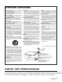
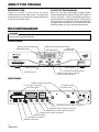
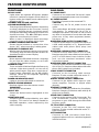
1
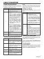
Pioneer 1000
Channel Number and
Time of Day Display
Remote Sensor Window
Message Light
Bypass Light
Smart Card slot
Clear/Multi-purpose button
Select button
Decrease volume
Channel scroll down
AC Power
Digital Audio output
used with the Y-Pb-Pr or the digital video output connector
Provides digital sound for channels.
Serial Port
USB
High-Speed peripheral
device connection
S-Video
Connects to S-Video
input of TV or VCR
Channel scroll up
Power ON/OFF Button
Increase volume
A/V Input
Connects to video and left/right (L/R) audio output
of external device
Cable Out
Connects to a coaxial
cable that sends analog
audio and video signals to
a TV or VCR.
Audio/video output
Connect to left/right (L/R) audio channels
of a stereo receiver or a TV with stereo sound
Copyright Time Warner Cable, All Rights Reserved
Cable In
Connects to cable
signal from your
service provider
DIGITAL HOME TERMINAL
BD-V1000 Series
Operating Instructions
CONTENTS
ABOUT THIS MANUAL ........................................ 4
BD-V1000 DIAGRAM ........................................... 4
FEATURE IDENTIFICATION ................................. 5
CONNECTIONS ................................................... 6
CABLE TV RECEPTION ....................................... 7
TROUBLESHOOTING .......................... Back Cover
TRADEMARKS AND COPYRIGHTS ..... Back Cover
WARNING
TO REDUCE THE RISK OF FIRE OR ELECTRIC SHOCK, DO NOT EXPOSE THIS APPLIANCE TO RAIN OR
MOISTURE.
IMPORTANT
CAUTION
RISK OF ELECTRIC SHOCK
DO NOT OPEN
The lightning flash with arrowhead, within an equilateral
triangle, is intended to alert the user to the presence of
uninsulated "dangerous voltage" within the product's
enclosure that may be of sufficient magnitude to
constitute a risk of electric shock to persons.
CAUTION:
TO PREVENT THE RISK OF ELECTRIC SHOCK, DO NOT
REMOVE COVER (OR BACK). NO USER-SERVICEABLE
PARTS INSIDE. REFER SERVICING TO QUALIFIED
SERVICE PERSONNEL.
The exclamation point within an equilateral triangle is
intended to alert the user to the presence of important
operating and maintenance (servicing) instructions in
the literature accompanying the appliance.
Trade Name: PIONEER
Model Number: BD-V1000 Series
FEDERAL COMMUNICATIONS COMMISSION DECLARATION OF CONFORMITY
THIS DEVICE COMPLIES WITH PART 15 OF THE FCC RULES. OPERATION IS SUBJECT TO THE
FOLLOWING TWO CONDITIONS: (1) THIS DEVICE MAY NOT CAUSE HARMFUL INTERFERENCE,
AND (2) THIS DEVICE MUST ACCEPT ANY INTERFERENCE RECEIVED, INCLUDING INTERFERENCE
THAT MAY CAUSE UNDESIRED OPERATION.
Responsible Party: PIONEER ELECTRONICS SERVICE, INC.
Address: P.O. Box 1760. Long Beach, CA 90801-1760
Phone: 1-800-872-4149
Webpage address: www.PioneerUSA.com
Information to User
Alteration or modifications carried out without appropriate authorization may invalidate the user’s right to
operate the equipment.
2
<BRB1050>
IMPORTANT SAFEGUARDS
READ INSTRUCTIONS – All the safety and
operating instructions should be read before
the appliance is operated.
RETAIN INSTRUCTIONS – The safety and
operating instructions should be retained
for future reference.
HEED WARNINGS – All warnings on the
appliance and in the operating instructions
should be adhered to.
FOLLOW INSTRUCTIONS – All operating and
usage instructions should be followed.
CLEANING – Do not use liquid cleaners or
aerosol cleaners. Use a polishing cloth or
soft dry cloth.
ATTACHMENTS – Do not use attachments not
recommended by appliance manufacturer
as they may cause hazards.
WATER AND MOISTURE – Do not use this
appliance near water – for example, near a
bathtub, wash bowl, kitchen sink, or laundry
tub, in a wet basement, or near a swimming
pool, etc.
ACCESSORIES – Do not place this appliance on
an unstable cart, stand, tripod, bracket, or
table. The appliance may fall, causing serious
injury to a child or adult, and serious damage
to the appliance. Use only with a cart, stand,
tripod, bracket, or table recommended by
the manufacturer, or sold with the appliance.
Any mounting of the appliance should follow
the manufacturer's instructions, and should
use a mounting accessory recommended by
the manufacturer.
CART – An appliance and cart combination
should be moved with care. Quick stops,
excessive force, and uneven surfaces may
cause the appliance and cart combination to
overturn.
POLARIZATION – This unit's power cord has a
polarized plug (one blade is wider than the
other). This plug will fit into the power outlet
only one way. This is a safety feature. If you
are unable to insert the plug fully into the
outlet, try reversing the plug. If the plug should
still fail to fit, contact your electrician to replace
your obsolete outlet. Do not defeat the safety
purpose of the polarized plug.
POWER-CORD PROTECTION – Power-supply
cords should be routed so that they are not
likely to be walked on or pinched by items
placed upon or against them. Pay particular
attention to cords at plugs, convenience
receptacles, and the point where they exit
from the appliance.
OUTDOOR ANTENNA GROUNDING – If an
outside antenna or cable system is connected
to the video product, be sure the antenna or
cable system is grounded so as to provide
some protection against voltage surges and
built-up static charges. Section 810 of the
National Electrical Code, ANSI/NFPA 70,
provides information with respect to proper
grounding of the mast and supporting
structure, grounding of the lead-in wire to an
antenna discharge unit, size of grounding
conductors, location of antenna-discharge
unit, connection to grounding electrodes, and
requirements for the grounding electrode. See
Figure A.
LIGHTNING – For added protection for the unit
during a lightning storm, unplug it from the
wall outlet and disconnect the cable system
input. This will prevent damage due to
lightning and power-line surges.
OVERLOADING – Do not overload wall outlets
and extension cords as this can result in a risk
of fire or electric shock.
OBJECT AND LIQUID ENTRY – Never push objects
of any kind into this appliance through
openings as they may touch dangerous voltage
points or short-out parts that could result in a
fire or electric shock. Never spill liquid of any
kind on the appliance.
SERVICING – Do not attempt to service this
appliance yourself as opening or removing
covers may expose you to dangerous
voltage or other hazards. Refer all servicing
to your cable company.
REPLACEMENT PARTS – When replacement
parts are required, be sure the service
technician has used replacement parts
specified by the manufacturer or have the
same characteristics as the original part.
Unauthorized substitutions may result in
fire, electric shock or other hazards.
SAFETY CHECK – Upon completion of any
service or repairs to this appliance, ask the
service technician to perform safety checks
to determine that the appliance is in proper
operating condition.
DAMAGE REQUIRING SERVICE – Unplug this
appliance from the wall outlet and call your
cable company under the following
conditions:
÷ When the power-supply cord or plug is
damaged.
÷ If liquid has been spilled, or objects have
fallen into the appliance.
÷ If the appliance has been exposed to rain or
water.
÷ If the appliance does not operate normally
by following the operating instructions.
Adjust only those controls that are covered
by the operating instructions. Improper
adjustment of other controls may result in
damage and will often require extensive
work by a qualified technician to restore
the appliance to its normal operation.
÷ If the appliance has been dropped or the
cabinet has been damaged.
÷ When the appliance exhibits a distinct
change in performance – this indicates a
need for service.
NEC – NATIONAL ELECTRICAL CODE
VENTILATION – Slots and openings in the
cabinet are provided for ventilation to ensure
reliable operation of the appliance and to
protect it from overheating. These openings
must not be blocked or covered. They should
never be blocked by placing the appliance
on a bed, sofa, rug, or other similar surface.
This appliance should never be placed near
or over a radiator or heat register. This
appliance should not be placed in a built-in
installation such as a bookcase or rack unless
proper ventilation is provided or the
manufacturer's instructions have been
adhered to.
POWER SOURCES – The appliance should be
operated only on the voltage indicated on
the product label. If you are not sure of the
type of power supply to your home, consult
your appliance dealer or local power
company.
ANTENNA
LEAD IN
WIRE
GROUND
CLAMP
ANTENNA
DISCHARGE UNIT
(NEC SECTION 810 – 20)
ELECTRIC
SERVICE
EQUIPMENT
GROUNDING CONDUCTORS
(NEC SECTION 810 – 21)
GROUND CLAMPS
FIG. A
POWER SERVICE GROUNDING
ELECTRODE SYSTEM
(NEC ART 250, PART H)
NOTE TO CATV SYSTEM INSTALLER:
This reminder is to call the CATV system installer’s attention to Article 820-40 of the NEC that pr
guidelines for proper grounding and, in particular, specifications that the cable grounding shall be co
to the grounding system of the building, as close to the point of cable entry as practical.
3
<BRB1050>
ABOUT THIS MANUAL
INTRODUCTION
FOCUS OF THIS MANUAL
Cable TV brings a wide array of home
entertainment to the cable viewer. To enjoy that
programming, your television must first be set up
to receive the cable signal.
Much of how your BD-V1000 Voyager Home
Terminal operates is determined by your cable TV
service provider. Those operating instructions
may be found in a separate manual. The purpose
of this guide is to assist you with connecting the
Voyager Home Terminal to a TV and/or VCR and
learning about its front- and rear-panel items.
BD-V1000 DIAGRAM
CAUTION:
Tampering with the Home Terminal or trying to force open the cover causes the Home Terminal to
stop functioning automatically.
FRONT PANEL
Remote sensor window
Channel number/time display
Power ON
BYPASS light
indicator light
MESSAGE light
MESSAGE
BYPASS
CH
SELECT
–
VOL
+
VOL
POWER
CH
SELECT key
Power button
CLEAR/multi-purpose key
Channel and volume control/
cursor movement keys
SmartCard slot
REAR PANEL
CABLE IN input connector
TO TV output connector
UL caution label
BD-V1000
*******
CAUTION
Tested To Comply
With FCC Standards
RISK OF ELECTRIC SHOCK
DO NOT OPEN
AC power outlet
AC power inlet
AC OUTLET
400W MAX
FOR HOME OR OFFICE USE
THIS DEVICE IS INTENDED TO BE ATTACHED TO A
RECEIVER THAT IS NOT USED TO RECEIVE OVER-THE-AIR
BROADCAST SIGNALS. CONNECTION OF THIS DEVICE
IN ANY OTHER FASHION MAY CAUSE HARMFUL
INTERFERENCE TO RADIO COMMUNICATIONS AND IS IN
VIOLATION OF THE FCC RULES, PART 15.
*********
CATV CONVERTER
MODEL BD-V1000
120 VAC
60 Hz
120V AC 60 Hz 26 W
PIONEER ELECTRONIC CORP.
MADE IN JAPAN
L
CABLE IN
AC INLET
TO TV
R
ETHERNET SERIAL USB
PORT
DIGITAL
AUDIO
S-VIDEO
OUT
VIDEO
OUT
AUDIO
OUT
UL
®
LISTED
295T
Baseband audio output connectors
Baseband video output connector
Baseband S-video output connector
Digital audio output connector
USB connector
Serial port connector
Ethernet connector
4
<BRB1050>
FEATURE IDENTIFICATION
FRONT PANEL
REAR PANEL
BYPASS LIGHT
Lights when the optional RF Bypass Adapter
module is switched to bypass mode. When in
bypass mode, the Adapter sends cable signals
directly to the TV.
CHANNEL AND VOLUME CONTROL/
CURSOR MOVEMENT KEYS
These keys have different functions, depending
on what is displayed on the TV screen. During
normal TV viewing, the 5/ ∇ (up/down) arrows
change the channel by stepping up or down one
channel at a time. The 2/3 (left/right) arrows
adjust the sound level up or down.
When a menu is displayed, these same keys
move the cursor up or down, left or right.
CHANNEL NUMBER/TIME DISPLAY
Shows channel number or current time. Also
shows “rEC” when recording is taking place.
CLEAR/MULTI-PURPOSE KEY
When a menu is displayed, returns you to normal
TV viewing. May also have special functions as
described in the on-screen display.
MESSAGE LIGHT
Blinks when the BD-V1000 receives a message
for you from the cable company, or an E-mail
message from another person.
POWER BUTTON
Turns on the BD-V1000 and lights the Power-On
indicator Light when pressed, or turns all off
when pressed again. May also control the AC
Power Outlet, depending on the BD-V1000’s
settings. (Refer to the separate operating
instruction manual.)
POWER ON INDICATOR LIGHT
Lights to show the BD-V1000 is turned on.
REMOTE SENSOR WINDOW
Receives signals from the remote control.
IMPORTANT:
Do not block this window.
SELECT KEY
Selects the desired action highlighted on the
screen.
SMARTCARD SLOT
Accepts a special card provided by your cable
company. This card is not always needed for
BD-V1000 operation, unless required by the
cable company.
AC POWER INLET
Connects to an unswitched 120-volt AC outlet,
using the detachable power cord (included).
AC POWER OUTLET
Provides AC power to the connected TV.
CAUTION:
Connect only the TV AC power cord to this
outlet.
This outlet allows 400 watts maximum power
consumption. To prevent the risk of fire or
damage to the Home Terminal, do not connect
any kind of equipment of more than 400 watts
power use, or any other equipment (toaster,
hair dryer, etc.).
BASEBAND AUDIO OUTPUT CONNECTORS
Connects to the stereo (L and R) audio inputs of
a VCR, audio amplifier, or TV. Requires audio
cables with male phono (RCA) plugs (not
included).
BASEBAND S-VIDEO OUTPUT CONNECTOR
Connects to the S-video input of a TV or VCR.
Requires special S-video cable (not included). If
your TV or VCR doesn’t have a similar S-video
jack, use the standard baseband video
connection instead.
BASEBAND VIDEO OUTPUT CONNECTOR
Connects to the standard baseband video input
of a VCR or TV. Requires video cables with male
phono (RCA) plugs (not included).
CABLE IN INPUT CONNECTOR
Connects to the incoming cable service.
Requires 75-ohm coaxial cable with male “F”type connectors (not included).
DIGITAL AUDIO OUTPUT CONNECTOR
Connects to the digital audio input on your
stereo amplifier, receiver or digital audio
decoder.
ETHERNET CONNECTOR
Connects to a 10Base-T LAN service, if available.
Requires Category 5 Ethernet cable with RJ45
plugs (not included).
SERIAL PORT CONNECTOR
Connects to the optional VCR Commander. The
VCR Commander controls recording of
programs on your VCR through the BD-V1000
program guide.
TO TV OUTPUT CONNECTOR
Connects to the TV’s VHF antenna input.
Requires 75-ohm coaxial cable with male “F”type connectors.
USB CONNECTOR
Connects to USB (Universal Serial Bus)equipped options such as a wireless keyboard
infrared receiver.
5
<BRB1050>
CONNECTIONS
BD-V1000 CONNECTIONS
These are some suggested basic hook-up
diagrams for the BD-V1000, both with and without
a VCR.
Simple Connection.
This is the simplest connection, but does not
provide stereo sound on analog channels.
BD-V1000 Home Terminal
CATV
Service
L
R
ETHERNET SERIAL USB
PORT
DIGITAL S-VIDEO VIDEO
AUDIO
CABLE IN
TO TV
AUDIO
Detachable AC
power cord
(included)
75-ohm VHF
ANTENNA IN
Unswitched
AC outlet
TV Set
Stereo Connection.
Provides stereo sound on all channels carrying
stereo signals. Tune your TV to watch the A/V or
Audio/Video input.
BD-V1000 Home Terminal
CATV
Service
L
R
ETHERNET SERIAL USB
PORT
DIGITAL S-VIDEO VIDEO
OUT
OUT
AUDIO
CABLE IN
TO TV
AUDIO
OUT
Detachable AC
power cord
(included)
Note:
Use either standard baseband video ports, or S-Video
ports if your TV and/or VCR
are so equipped.
INPUTS
S-VIDEO
R
VIDEO
Unswitched
AC outlet
L
AUDIO
TV Set
VCR Connection.
Provides stereo hookup to TV through VCR. Select
the A/V or Audio/Video input on both your TV and
VCR.
BD-V1000 Home Terminal
CATV
Service
L
R
ETHERNET SERIAL USB
PORT
DIGITAL S-VIDEO VIDEO
OUT
OUT
AUDIO
CABLE IN
TO TV
AUDIO
OUT
Detachable AC
power cord
(included)
VCR
IN
IN
S-VIDEO VIDEO
R
L
OUT
IN
Note:
Use either standard baseband video ports, or S-Video
ports if your TV and/or VCR
are so equipped.
R
L
INPUTS
S-VIDEO
VIDEO
R
L
AUDIO
TV Set
6
<BRB1050>
AUDIO
OUT
Unswitched
AC outlet
CABLE TV RECEPTION
CONNECTION PROCEDURES
Connect your equipment as shown in the figures
on page 6. Use the first table if you are only
connecting the BD-V1000 to a TV.
STEP
ACTION
1
Connect cable service to BD-V1000
CABLE IN (input connector).
¶ If TV has video and stereo audio
inputs:
2
Follow the Stereo Connection
diagram on page 6. Connect BDV1000 L/R AUDIO OUT and VIDEO
OUT to the corresponding IN jacks
on the TV, using shielded RCA
(phono) jumper cables.
If TV VIDEO IN is a 4-pin S-Video
jack, connect BD-V1000 S-VIDEO
OUT to TV S-VIDEO IN using a
special S-Video jumper cable.
Leave BD-V1000 VIDEO OUT
unconnected.
NOTE:
When disconnecting the BD-V1000, follow these
steps in reverse order. Be sure to unplug the BDV1000’s power cord first.
SETTING UP THE TV
Follow the steps in the table to set up your TV for
cable.
STEP
Tune TV to channel 3 or 4.
1
3
Plug TV AC cord into BD-V1000 AC
outlet.
4
Plug BD-V1000 AC cord into an AC
outlet that is not controlled by a switch.
If you have a VCR, follow the procedure below to
connect it between the BD-V1000 and the TV:
Other documentation that came
with your BD-V1000 may explain
how to switch the BD-V1000
output channel between 3 and 4.
¶ If you used the Stereo or VCR
Connection method:
Select the A/V (Audio/Video)
input setting on your TV.
¶ If TV has no video/audio inputs:
Follow the Simple Connection
diagram on page 6. Connect BDV1000 TO TV (output) connector to
the TV VHF ANTENNA INPUT.
If TV VHF ANTENNA INPUT is a
300-ohm twin-lead (with two
screws), then use a 75 ohm - 300
ohm adapter.
ACTION
¶ If you used the Simple
Connection method:
Use your remote control’s TV
POWER button to turn the TV on
and off.
2
Exception:
TV sets without remote control can
be turned on through the BDV1000. Leave the TV power switch
on. Use the on-screen menu to
change the BD-V1000’s outlet from
UNSWITCHED to SWITCHED. Use
the BD-V1000 front panel or
remote control POWER button to
turn the TV on and off.
TURNING OFF THE BD-V1000
STEP
ACTION
To turn off the BD-V1000 home terminal, press the
CBL POWER button on the remote control, or the
POWER button on the BD-V1000.
1
Follow the VCR Connection
diagram on page 6. Connect cable
service to BD-V1000 CABLE IN
(input connector).
You can use your remote’s TV POWER button to
turn TV on/off if you have set up the remote with
the correct TV code.
Connect BD-V1000 outputs to VCR
inputs using the same criteria and
procedures as in step 2 of the table
above for TV connection.
VCR RECORDING
2
3
Connect the VCR outputs to the TV
inputs, again using the same
criteria and procedures.
4
Connect TV AC cord to BD-V1000
AC outlet.
5
Connect VCR and BD-V1000 AC
cords to AC outlets that are not
controlled by a switch.
The BD-V1000 has an optional VCR Commander
that lets you automatically record programs.
Please refer to the separate VCR Commander
manual for installation instructions.
7
<BRB1050>
TROUBLESHOOTING
NO TV PICTURE?
Use the checklist in the table if you followed all the
instructions but still do not see a picture on your
television.
CHECK
STEP
ACTION
1
Is cable service connected to
BD-V1000
CABLE
IN
connector?
2
Is a cable connected between
BD-V1000 TO TV connector
and TV input connector; or
between BD-V1000 VIDEO and
L/R AUDIO output connectors
and TV VIDEO and L/R AUDIO
input connectors?
3
Is the BD-V1000 AC cord
plugged in to an unswitched
AC outlet?
4
Are both BD-V1000 and TV
turned on?
5
Is your TV tuned to the correct
channel (3 or 4), or set to
display the A/V (audio/video)
input? If no picture on one
channel, try the other.
6
Has there been a recent
lightning storm? If so, reset
your BD-V1000. (See the
“Lightning Protection Circuit”
section.)
LIGHTNING PROTECTION CIRCUIT
The BD-V1000 features a lightning protection
circuit. During a lightning storm, this circuit may
activate to protect the rest of the circuit from
damage. If this occurs, the terminal will appear to
not work at all. To restore operation, simply unplug
the unit’s AC power cord for at least one minute,
and plug it in again.
TRADEMARKS AND COPYRIGHTS
DOLBY DIGITAL
PowerKEY
Manufactured under license from Dolby
Laboratories. “Dolby”, “AC-3” and the double-D
symbol are trademarks of Dolby Laboratories.
Confidential and Unpublished Works, ©1992 —
1997 Dolby Laboratories, Inc. All rights reserved.
PowerKEY is a registered trademark, and the
PowerKEY design is a trademark, of ScientificAtlanta, Inc.
Published by Pioneer Electronic Corporation.
Copyright © 1998 Pioneer Electronic Corporation.
All rights reserved.
PIONEER ELECTRONIC CORPORATION
Industrial and Business Products Merchandising Division:
4-1, Meguro 1-Chome, Meguro-ku, Tokyo 153-8654, Japan
PIONEER DIGITAL TECHNOLOGIES, INC.
Broadband Applications Division:
2210 West Olive Avenue, 2nd Floor, Burbank, CA 91506, U.S.A. TEL: 818-295-6650
PIONEER NEW MEDIA TECHNOLOGIES, INC.
Cable and Broadcast Systems Division:
2265 East 220th Street, Long Beach, CA 90810, U.S.A. TEL: 310-952-2111
PIONEER ELECTRONICS OF CANADA, INC.
Industrial Products Department:
300 Allstate Parkway, Markham, Ontario L3R 0P2, Canada TEL: 905-479-4411
PIONEER ELECTRONICS AUSTRALIA PTY. LTD. 178-184 Boundary Road, Braeside, Victoria 3195, Australia TEL:+61-3-9586-6300
PIONEER ELECTRONICS ASIACENTRE PTE. LTD. 501 Orchard Road, #10-00, Lane Crawford Place, Singapore 0923
TEL: +65-735-9011
8
<BRB1050>
FAX: +65-735-9022
Printed in Japan <BRB1050-D>