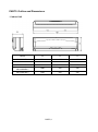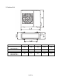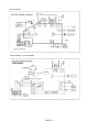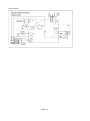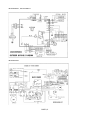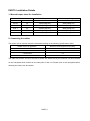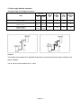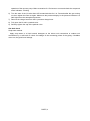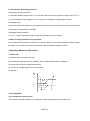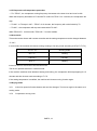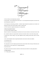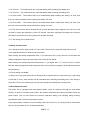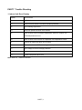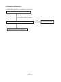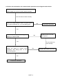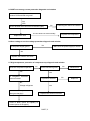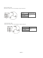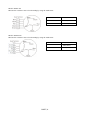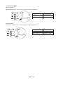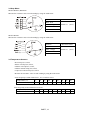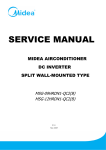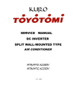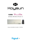
1
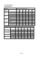
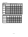
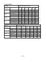
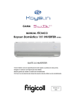
LUV INVERTER SERIES Service Manual 42/38LUVH025N-1 42/38LUVH035N-1 42/38LUVH045N-1 42/38LUVH055N-1 42/38LUVH065N-1 42/38LUVH075N-1 CONTENTS PART1. Safety Precaution PART2. Outline and Dimensions PART3. Refrigerant Cycle Diagram PART4. Wiring Diagram PART5. Installation Details PART6. Operation Description PART7. Trouble Shooting PART8. Capacity Table PART1. Precaution 1. Safety Precaution To prevent injury to the user or other people and property damage, the following instructions must be followed. Incorrect operation due to ignoring instruction will cause harm or damage. Before service the unit, be sure to read this service manual at first. 2. Warning Installation Do not use a defective or underrated circuit breaker. Use this appliance on a dedicated circuit. There is risk of fire or electric shock. For electrical work, contact the dealer, seller, a qualified electrician, or an authorized service center. Do not disassemble or repair the product, there is risk of fire or electric shock. Always ground the product. There is risk of fire or electric shock. Install the panel and the cover of control box securely. There is risk of fire of electric shock. Always install a dedicated circuit and breaker. Improper wiring or installation may cause fore or electric shock. Use the correctly rated breaker of fuse. There is risk of fire or electric shock. Do not modify or extend the power cable. There is risk of fire or electric shock. Do not install, remove, or reinstall the unit by yourself (customer). There is risk of fire, electric shock, explosion, or injury. Be caution when unpacking and installing the product. Sharp edges could cause injury, be especially careful of the case edges and the fins on the condenser and evaporator. PART1, 1 For installation, always contact the dealer or an authorized service center. Do not install the product on a defective installation stand. Be sure the installation area does not deteriorate with age. If the base collapses, the air conditioner could fall with it, causing property damage, product failure, and personal injury. Do not let the air conditioner run for a long time when the humidity is very high and a door or a window is left open. Take care to ensure that power cable could not be pulled out or damaged during operation. There is risk of fire or electric shock. Do not place anything on the power cable. There is risk of fire or electric shock. Do not plug or unplug the power supply plug during operation. There is risk of fire or electric shock. Do not touch (operation) the product with wet hands. Do not place a heater or other appliance near the power cable. There is risk of fire and electric shock. Do not allow water to run into electrical parts. It may cause fire, failure of the product, or electric shock. Do not store or use flammable gas or combustible near the product. There is risk of fire or failure of product. Do not use the product in a tightly closed space for a long time. Oxygen deficiency could occur. When flammable gas leaks, turn off the gas and open a window for ventilation before turn the product on. If strange sounds or smoke comes from product, turn the breaker off or disconnect the power supply cable. There is risk of electric shock or fire. Stop operation and close the window in storm or hurricane. If possible, remove the product from the window before the hurricane arrives. PART1, 2 There is risk of property damage, failure of product, or electric shock. Do not open the inlet grill of the product during operation. (Do not touch the electrostatic filter, if the unit is so equipped.) There is risk of physical injury, electric shock, or product failure. When the product is soaked, contact an authorized service center. There is risk of fire or electric shock. Be caution that water could not enter the product. There is risk of fire, electric shock, or product damage. Ventilate the product from time to time when operating it together with a stove etc. There is risk of fire or electric shock. Turn the main power off when cleaning or maintaining the product. There is risk of electric shock. When the product is not be used for a long time, disconnect the power supply plug or turn off the breaker. There is risk of product damage or failure, or unintended operation. Take care to ensure that nobody could step on or fall onto the outdoor unit. This could result in personal injury and product damage. CAUTION Always check for gas (refrigerant) leakage after installation or repair of product. Low refrigerant levels may cause failure of product. Install the drain hose to ensure that water is drained away properly. A bad connection may cause water leakage. Keep level even when installing the product. It can avoid vibration of water leakage. Do not install the product where the noise or hot air from the outdoor unit could damage the neighborhoods. It may cause a problem for your neighbors. Use two or more people to lift and transport the product. Do not install the product where it will be exposed to sea wind (salt spray) directly. PART1, 3 It may cause corrosion on the product. Corrosion, particularly on the condenser and evaporator fins, could cause product malfunction or inefficient operation. Operational Do not expose the skin directly to cool air for long time. (Do not sit in the draft). Do not use the product for special purposes, such as preserving foods, works of art etc. It is a consumer air conditioner, not a precision refrigerant system. There is risk of damage or loss of property. Do not block the inlet or outlet of air flow. Use a soft cloth to clean. Do not use harsh detergents, solvents, etc. There is risk of fire, electric shock, or damage to the plastic parts of the product. Do not touch the metal parts of the product when removing the air filter. They are very sharp. Do not step on or put anything on the product. (outdoor units) Always insert the filter securely. Clean the filter every two weeks or more often if necessary. A dirty filter reduces the efficiency of the air conditioner and could cause product malfunction or damage. Do not insert hands or other objects through air inlet or outlet while the product is operated. Do not drink the water drained from the product. Use a firm stool or ladder when cleaning or maintaining the product. Be careful and avoid personal injury. Replace the all batteries in the remote control with new ones of the same type. Do not mix old and new batteries or different types of batteries. There is risk of fire or explosion. Do not recharge or disassemble the batteries. Do not dispose of batteries in a fire. They may burn of explode. If the liquid from the batteries gets onto your skin or clothes, wash it well with clean water. Do not use the remote of the batteries have leaked. PART1, 4 PART2. Outline and Dimensions 1. Indoor Unit Model W D H 42LUVH025N-1 790 195 265 42LUVH035N-1 920 225 292 42LUVH045N-1 920 225 292 42LUVH055N-1 42LUVH065N-1 1080 230 330 42LUVH075N-1 1250 230 325 PART2, 1 2. Outdoor Unit Model 38LUVH025N-1 38LUVH035N-1 L1 W1 H L2 W2 760 285 590 530 290 38LUVH045N-1 760 285 590 530 290 38LUVH055N-1 845 320 700 560 335 38LUVH065N-1 38LUVH075N-1 900 315 860 590 333 PART2, 2 PART3. Refrigerant Cycle Diagram INDOOR OUTDOOR CHECK VALVE (Heating Model only) LIQUID SIDE 2-WAY VALVE CAPILIARY TUBE HEAT EXCHANGE (EVAPORATOR) HEAT EXCHANGE (CONDENSER) GAS SIDE REVERSING VALVE (Heating Model only) 3-WAY VALVE ACCUMULATOR COOLING COMPRESSOR PART3, 1 HEATING PART4. Wiring Diagram 1. Indoor Unit 42LUVH025N-1 42LUVH035N-1 PART4, 1 42LUVH045N-1 42LUVH055N-1, 42LUVH065N-1 PART4, 2 42LUVH075N-1 PART4, 3 2. Outdoor Unit 38LUVH025N-1, 38LUVH035N-1 38LUVH045N-1 PART4, 4 38LUVH055N-1, 38LUVH065N-1 38LUVH075N-1 PART4, 5 PART5. Installation Details 1. Wrench torque sheet for installation Outside diameter Torque Additional tightening torque mm inch N.cm N.cm Ф6.35 1/4 1500(153kgf.cm) 1600(163kgf.cm) Ф9.52 3/8 2500(255kgf.cm) 2600(265kgf.cm) Ф12.7 1/2 3500(357kgf.cm) 3600(367kgf.cm) Ф16 5/8 4500(459kgf.cm) 4700(479kgf.cm) Ф19 3/4 6500(663kgf.cm) 6700(683kgf.cm) 2. Connecting the cables The power cord of connect should be selected according to the following specifications sheet. Rated current of appliance Nominal cross-sectional area (mm²) >3 and ≤6 0.75 >6 and ≤10 1 >10 and ≤16 1.5 >16 and ≤25 2.5 The cable size and the current of the fuse or switch are determined by the maximum current indicated on the nameplate which located on the side panel of the unit. Please refer to the nameplate before selecting the cable, fuse and switch. PART5, 1 3. Pipe length and the elevation The pipe length and refrigerant amount: Pipe size Model Standard length (m) Max. Elevation B (m) Max. Length A (m) Additional refrigerant (g/m) Gas Liquid 42/38LUVH025N-1 3/8’’ (Ф9.53) 1/4’’ (Ф6.35) 5 8 20 20 42/38LUVH035N-1 42/38LUVH045N-1 1/2’’ (Ф12.7) 1/4’’ (Ф6.35) 5 8 20 20 42/38LUVH055N-1 42/38LUVH065N-1 42/38LUVH075N-1 5/8’’ (Ф16.0) 3/8’’ (Ф9.53) 5 10 25 40 Caution: The capacity test is based on the standard length and the maximum permissive length is based on the system reliability. The oil trap should be installed per 5-7 meter PART5, 2 4. Air purging with vacuum pump Air and moisture in the refrigerant system have undesirable effects as below: ● Pressure in the system rises. ● Operating current rises. ● Cooling or heating efficiency drops. ● Moisture in the refrigerant circuit may freeze and block capillary tubing. ● Water may lead to corrosion of parts in the refrigerant system. Therefore, the indoor units and the pipes between indoor and outdoor units must be leak tested and evacuated to remove gas and moisture from the system. Air purging with vacuum pump (Indoor unit) (Outdoor unit) (Liquid side) Two-way valve Close (Gas side) Three-way valve Manifold valve Compound meter Pressure gauge -76cmHg Lo Handle Lo Charge hose Close Hi Handle Hi Charge hose Vacuum pump adaptor Vacuum pump Procedure 1) Completely tighten the flare nuts of the indoor and outdoor units, connect the manifold valve charge. 2) Connect the charge hose connection to the vacuum pump. 3) Fully open the handle Lo of the manifold valve. 4) Operate the vacuum pump to evacuate. After starting evacuation, slightly loose the flare nut of the Lo valve on the gas pipe side and check the air is entering. (Operation noise of the vacuum pump changes and a compound meter indicates 0 stead of minutes) 5) After the evacuation is complete, fully close the handle Lo valve of the manifold valve and stop the PART5, 3 6) 7) 8) 9) operation of the vacuum pump. Make evacuation for 15 minutes or more and check the compound meter indicates -76cmHg. Turn the stem of the Hi valve about 45°counterclockwise for 6 or 7seconds after the gas coming out, then tighten the flare nut again. Make sure the pressure display in the pressure indicator is a little higher than the atmosphere pressure. Remove the charge hose from the Lo pressure charge hose. Fully open the Hi and Lo packed valve. Securely tighten the cap of the packed valve. Gas leak check Soap water method Apply soap water or a liquid neutral detergent on the indoor unit connections or outdoor unit connections by a soft brush to check for leakage of the connecting points of the piping. If bubbles come out, the pipes have leakage. PART5, 4 PART6. Operation Description 1. Abbreviation T1: Indoor room temperature T2: Coil temperature of evaporator T3: Coil temperature of condenser T4: Outdoor ambient temperature T5: Compressor discharge temperature 2. Main Protection 2.1 Three Minutes Delay at restart for compressor 1 minute delay for the 1st time start-up and 3 minutes delay for others. 2.2 Temperature protection of compressor top The unit will stop working when the compressor top temperature protector cut off, and will restart after the compressor top temperature protector restart. 2.3 Temperature protection of compressor discharge When the compressor discharge temperature is getting higher, the running frequency will be limited as below rules: ---Compressor discharge temperature T5>115℃ for 5s, compressor stops. ---108<T5<115℃, decrease the frequency to the lower level every 3 minutes. ---90<T5<105℃, keep running at the current frequency. ----T5<90℃, no limit for frequency. 2.4 Fan Speed is out of control When Indoor Fan Speed keeps too low (300RPM) for certain time, the unit will stop and the LED will display the failure 2.5 Inverter module Protection The Inverter module has a protection function about current, voltage and temperature. If these protections happen, the corresponding code will display on indoor unit and the unit will stop working. 2.6 Indoor fan delayed open function When the unit starts up, the louver will be active immediately and the indoor fan will open 10s later. If the unit runs in heating mode, the indoor fan will be also controlled by anti-cold wind function. PART6, 1 2.7 Compressor preheating functions Preheating permitting condition: If T4(outdoor ambient temperature)<3℃ and the machine connects to power supply newly or if T4< 3℃ and compressor has stopped for over 3 hours, the compressor heating cable will work. Preheating mode: A weak current flow through the coil of compressor from the wiring terminal of the compressor, then the compressor is heated without operation. Preheating release condition: If T4>5℃ or the compressor starts running, the preheating function will stop. 2.8 Zero crossing detection error protection If AC detects time interval is not correct for continuous 240s, the unit will stop and the LED will display the failure. The correct zero crossing signal time interval should be between 6-13ms. 3 Operation Modes and Functions 3.1 Fan mode (1) Outdoor fan and compressor stop. (2) Temperature setting function is disabled, and no setting temperature is displayed. (3) Indoor fan can be set to high/med/low/auto. (4) The louver operates same as in cooling mode. (5) Auto fan: 27.5 High 27 25.5 Medium 25 Low 3.2 Cooling Mode 3.2.1 Compressor running rules The maximum operation frequency of compressor after starting submits to following rule. PART6, 2 Fmax=F4 45 43 Fmax=F7 40 38 Fmax=F8 30 28 Fmax=F6 22 20 Fmax=F3 If users switch on AC by remote controller, the compressor will run at the Fmax frequency for 7 minutes according to the outdoor ambient temperature During the 7 minutes, the frequency limitation is active. 7 minutes later, the compressor running frequency will be controlled as below: 3.5 A 3.0 B 2.5 C 2.0 D 1.5 E 1.0 F 0.5 -0.5 G -1.0 H While Temperature A B C D E F G Frequency zone F8 F8 F7 F6 F5 F3 F1 Note: When T1-Ts keeps in the same temperature zone for 3 minutes, the compressor will run as the below rules: A~E: Increase the frequency to the higher level until to F8. F: Keep the current frequency. PART6, 3 G: Decrease the frequency to the lower level until to F1. H: Run at F1 for 1h.(if T1-Ts<-2℃, the compressor will stop) Meanwhile, the compressor running frequency is limited by the current. Off I3COOL Decrease I2COOL Hold I1COOL Resume Off: Compressor stops. Decrease: Decrease the running frequency to the lower level. Hold: Keep the current frequency. Resume: No limitation for frequency. Note: When AC is in “hold” zone for 3 minutes, the compressor frequency will rise to the higher level.(frequency will increase twice at most) 3.2.2 Outdoor fan running rules 22 High 20 Low 3.2.3 Indoor fan running rules In cooling mode, indoor fan runs all the time and the speed can be selected as high, medium, low and auto. Auto fan in cooling mode acts as follow: PART6, 4 4 High 3 Medium 1.5 1 Low 3.2.4 Condenser temperature protection ---55℃<T3<60℃, the compressor frequency will decrease to the lower level until to F1 and then runs at F1.If T3<54℃, the compressor will keep running at the current frequency. ---T3<52℃, the compressor will not limit the frequency and resume to the former frequency. ---T3>60℃ for 5 seconds, the compressor will stop until T3<52℃. 3.2.5 Evaporator temperature protection ---T2<0℃, the compressor will stop and restart when T2>=5℃. ---0℃≦T2<4℃, the compressor frequency will be limited and decreased to the lower level ---4℃≤T2≤7℃, the compressor will keep the current frequency. ---T2>7℃, the compressor frequency will not be limited. 3.3 Heating Mode 3.3.1 Compressor running rules The maximum operation frequency of the compressor after starting submits to the following rule. PART6, 5 34 33 28 27 Off Fmax=F2 25 24 Fmax=F3 22 21 Fmax=F4 19 18 Fmax=F5 17 16 Fmax=F6 15 14 Fmax=F7 12 11 Fmax=F8 6 5 Fmax=F9 Fmax=F10 If users switch on AC by remote controller, the compressor will run at the Fmax frequency for 7 minutes according to outdoor ambient temperature During the 7 minutes, the frequency limitation is active. 7 minutes later, the compressor running frequency will be controlled as below: PART6, 6 H H +5.0 +4.5 G +3.5 +3.0 F +2.5 E +2.0 D C +1.5 B +1.0 +0.5 A While Temperature Frequency zone ΔT=0℃ as default. A B C D E F G F10 F9 F8 F7 F5 F3 F1 Note: When T1-Ts keeps in the same temperature zone for 3 minutes, the compressor will run as the below rules: A~E: Increase the frequency to the higher level until to F10. F: Keep the current frequency. G: Decrease the frequency to the lower level until to F1. H: Run at F1 for 1h.(if T1-Ts-ΔT >6℃, the compressor will stop) Meanwhile, the compressor running frequency is limited by the current. PART6, 7 Off I3HEAT Decrease I2HEAT Hold I1HEAT Resume Off: Compressor stops. Decrease: Decrease the running frequency to the lower level. Hold: Keep the current frequency. Resume: No limitation for frequency. Note: When AC is in “hold” zone for 3 minutes, the compressor frequency will rise to the higher level. (The frequency will increase twice at most) 3.3.2 Outdoor fan running rules 17 Low 15 High 3.3.3 Indoor fan running rules PART6, 8 Setting 44 38 37 Low 34 33 Breeze 17 Off If the compressor stops caused by the room temperature rising, the indoor fan will be forced to run 127 seconds with breeze. During this period, the anti-cold-wind is disabled. If the machine runs in rating capacity test mode, the indoor fan will run with rating speed and the anti-cold-wind function is disabled. Indoor fan speed can be set as high, medium, low or auto fan and the anti-cold-wind function is preferential. Auto fan action in heating mode: Low 2.5 2 Medium 1.5 1 High 3.3.4 Defrosting mode Condition of defrosting: ----T4>0℃, When the units are running, if the following two items are satisfied, the units start defrosting: The units run with T3<3℃ for 40 minutes and T3 keeps lower than TCDI℃ for more than 3 minutes. The units run with T3<3℃ for 80 minutes and T3 keeps lower than TCDI+2℃ for more than 3 minutes. PART6, 9 While TCDI=-6℃. ----T4<0℃, If the 1st condition and 2nd condition items are satisfied, then the program judges if T2 has decreased more than 5℃.When T2 has decreased more than 5℃, enter the defrosting mode. ----No matter what value T4 is, if the machine runs with T3<3℃ for more than 120 minutes and T3 keeps lower than TCDI+4℃ for more than 3 minutes, the machine will enter defrosting mode no matter if T2 drops more than 5℃ or not. Condition of ending defrosting: If any one of the following items is satisfied, the defrosting will finish and the machine will turn to normal heating mode. ----T3 rises to be higher than TCDE1℃. ----T3 keeps to be higher than TCDE2℃ for 80 seconds. ----The machine has run for 10 minutes in defrosting mode. While TCDE1=15℃, TCDE2=8℃ for 18k, 24k model. TCDE1=12℃, TCDE2=8℃ for other models. PART6, 10 Defrosting action: or PART6, 11 3.3.5 Evaporator coil temperature protection ----T2> TEH2℃, the compressor running frequency decreases to the lower level and runs for 20s. When the frequency decreases to F2 and the T2 is still over TEH2℃ for 3 minutes, the compressor will stop. ----T2<48℃ or T2 stays in 48℃~ TEH2℃ for 6 minutes, the frequency will not be limited by T2. ----T2>60℃, the compressor will stop and restart when T2<48℃. While TEH2=55℃ for 24k model, TEH2=53℃ for other models. 3.4 Auto-mode This mode can be chosen with remote controller and the setting temperature can be changed between 17~30℃. In auto mode, the machine will choose cooling, heating or fan-only mode according to ΔT (ΔT =T1-Ts). ΔT=T1-Ts Running mode ΔT>1℃ Cooling -1<ΔT≤1℃ Fan-only ΔT≤-1℃ Heating Indoor fan will run at auto fan of the relevant mode. The louver operates same as in relevant mode. If the machine switches mode between heating and cooling, the compressor will keep stopping for 15 minutes and then choose mode according to T1-Ts. If the setting temperature is modified, the machine will choose running function again. 3.5 Drying mode 3.5.1 Indoor fan speed is fixed at breeze and can’t be changed. The louver angle is the same as in cooling mode. 3.5.2 Compressor running rules PART6, 12 2.5 F3 2.0 1.5 F2 1.0 0.5 F1 0.0 F1 3.5.3 Low indoor room temperature protection In drying mode, if room temperature is lower than 10℃, the compressor will stop and not resume until room temperature exceeds 12℃. 3.5.4 Evaporator anti-freezing protection, condenser high temperature protection and outdoor unit frequency limit are active and the same as that in cooling mode. 3.5.5 The outdoor fan operates the same as in cooling mode. 3.6 Forced operation function 3.6.1 Enter forced operation function: When the machine is off, pressing the touch button will carry the machine to forced auto mode. After this, if press the button once again within 5 seconds, the machine will turn into forced cooling mode. In forced auto, forced cooling or any other operation mode, pressing touch button will turn off the machine. 3.6.2 In forced operation mode, all general protections and remote control are available. 3.6.3 Operation rules: Forced cooling mode: The compressor runs at F2 frequency and indoor fan runs as breeze. After running for 30 minutes, the machine will turn to auto mode as 24℃ setting temperature. Forced auto mode: The action of forced auto mode is the same as normal auto mode with 24℃ setting temperature. 3.7 Timer function 3.7.1 Timing range is 24 hours. PART6, 13 3.7.2 Timer on. The machine will turn on automatically when reaching the setting time. 3.7.3 Timer off. The machine will turn off automatically when reaching the setting time. 3.7.4 Timer on/off. The machine will turn on automatically when reaching the setting “on” time, and then turn off automatically when reaching the setting “off” time. 3.7.5 Timer off/on. The machine will turn off automatically when reaching the setting “off” time, and then turn on automatically when reaching the setting “on” time. 3.7.6 The timer function will not change the AC current operation mode. Suppose AC is off now, it will not start up firstly after setting the “timer off” function. And when reaching the setting time, the timer LED will be off and the AC running mode has not been changed. 3.7.7 The setting time is relative time. 3.8 Sleep function mode 3.8.1 Operation time in sleep mode is 7 hours. After 7 hours the AC quits this mode and turns off. 3.8.2. Operation process in sleep mode is as follow: When cooling, the setting temperature rises 1℃ (be lower than 30℃) every one hour, 2 hours later the setting temperature stops rising and indoor fan is fixed as low speed. When heating, the setting temperature decreases 1℃ (be higher than 17℃) every one hour, 2 hours later the setting temperature stops rising and indoor fan is fixed as low speed. (Anti-cold wind function has the priority) 3.2 Timer setting is available 3.3 When user uses timer off function in sleep mode (or sleep function in timer off mode), if the timing is less than 7 hours, sleep function will be cancelled when reaching the setting time. If the timing is more than 7 hours, the machine will not stop until reaches the setting time in sleep mode. 3.9 Auto-Restart function The indoor unit is equipped with auto-restart function, which is carried out through an auto-restart module. In case of a sudden power failure, the module memorizes the setting conditions before the power failure. The unit will resume the previous operation setting (not including swing function) automatically after 3 minutes when power returns. If the memorization condition is forced cooling mode, the unit will run in cooling mode for 30 minutes and turn to auto mode as 24℃ setting temperature PART6, 14 If AC is off before power off and AC is required to start up now, the compressor will have 1 minute delay when power on. Other conditions, the compressor will have 3 minutes delay when restarts. 3.10 Ionizer function (optional) The indoor unit is equipped with Ionizer, which is controlled by the CLEAN AIR button on the remote controller. When the unit is turned on, press the CLEAN AIR button to activate the function. Press it again to stop the function. During the time when Ionizer is controlled by remote controller, Ionizer will be turned off automatically if indoor fan stops running due to malfunctions or anti-cold-wind. When indoor fan restarts after malfunctions being eliminated and anti-cold-wind being released, Ionizer will be available again. 3.11 8℃ Heating(optional) In heating operation, the preset temperature of the air conditioner can be as lower as 8℃, which keeps the room temperature steady at 8℃ and prevents household things freezing when the house is unoccupied for a long time in severe cold weather. PART6, 15 PART7. Trouble Shooting 1. Indoor Unit Error Display Display LED STATUS E0 EEPROM parameter error E1 Indoor unit and outdoor unit communication protection E2 Zero-crossing signal error E3 Indoor fan speed has been out of control E5 Open or short circuit of outdoor temperature sensor or outdoor unit EEPROM parameter error E6 Open or short circuit of room or evaporator coil temperature sensor E7 Outdoor fan speed has been out of control P0 IBM malfunction or IGBT over-strong current protection P1 Over voltage or too low voltage protection P2 Temperature protection of compressor top. P4 Inverter compressor drive error Note: E4 & P3: Reserved function. PART7, 1 2. Diagnosis and Solution 2.1 EEPROM parameter error diagnosis and solution Shut off the power supply and turn on it 5s later The problem comes out again Is the EEPROM chip plugged in indoor unit PCB well? Replace the main PCB of indoor unit PART7, 2 No Correct the connection 2.2 Indoor unit and outdoor unit communication protection error diagnosis and solution Turn off the power supply, after 1 minute, connect the power supply, turn on the unit with remote controller The unit does not work normally Check the wiring between indoor unit and outdoor unit. Is the connection of L, N, S and GND good? No Reconnect and retest Yes Is the LED4(red) bright and LED1(yellow) blinking on outdoor PCB? Yes No The power supply for outdoor PCB is fail. Check the wiring on outdoor PCB comparing with wiring plate. Is the connection good? Replace indoor unit PCB and repower The unit does not work normally Yes No Correct the connection PART7, 3 Replace the outdoor unit e-box outdoor e-box. 2.3 Fan speed has been out of control diagnosis Shut off the power supply and turn on it 5s later The unit does not work normally No Turn off the unit, rotate the cross fan. Does it rotate freely? Disassemble the connection between fan and motor, check if the bearing is normal. If not, change the bearing. If yes, follow the below step. Yes Is the fan motor connector and connection good? Yes Yes Is the voltage being applied to the fan motor? Replace the fan motor No Replace the PCB 2.4 Open or short circuit of temperature sensor diagnosis and solution Check the connections between the sensors and the PCB. Are the connections good? Yes Replace the sensor and check if the errors happen again? Yes PART7, 4 Replace the outdoor unit PCB 2.5 IGBT over-strong current protection diagnosis and solution Check whether the connections between outdoor PCB and IPM are good? Yes YES Check whether the IPM is fixed to radiator tightly No Fastening the IPM to the radiator The unit does not work normally Replace the IPM Replace the compressor 2.6 Over voltage or too low voltage protection diagnosis and solution No Is the power supply good? Make sure the power supply is normal. Yes Replace the outdoor unit e-box. 2.7 High temperature protection of compressor top diagnosis and solution Does the compressor operate? No Yes Is refrigerant circulation volume normal? Reconnect it Yes Is protector normal? No, Charge refrigerant Is the abnormality the same after gas charging? No Is the connection good? No Yes Replace the outdoor unit PCB. There is block (Such as capillary or welded points of the pipes.) PART7, 5 Replace it 2.8 Inverter compressor drive error diagnosis and solution Is the connection of compressor good? Is the wiring sequence right? The voltage range proper? No Reconnect and retry Yes Replace the outdoor unit PCB No Replace inverter compressor. 2.9 Zero crossing detection error This is alarm signal when the main chip can’t detect over-zero signal. When such failure occurs, the main control board must have fault. 3. Key parts checking 3.1 Compressor checking Model: DA108X1C-20FZ3 Measure the resistance value of each winding by using the multi-meter. Position Blue - Red Blue - Black Resistance Value 0.71Ω (20℃) Red - Blue Model: DA130S1C-20FZ Measure the resistance value of each winding by using the multi-meter. Position Blue - Red Blue - Black Red - Blue PART7, 6 Resistance Value 0.95Ω (20℃) Model: DA150S1C-20FZ Measure the resistance value of each winding by using the multi-meter. Position Blue - Red Blue - Black Resistance Value 0.95Ω (20℃) Red - Blue Model: DA250S2C-30MT Measure the resistance value of each winding by using the multi-meter. Position Blue - Red Blue - Black Red - Blue PART7, 7 Resistance Value 0.55Ω (20℃) 3.2 Outdoor Fan Motor Model: YDK24-6G Measure the resistance value of each winding by using the multi-meter. Position Resistance Value Black - Red 372Ω (20℃) Blue - Red 249Ω (20℃) Yellow - Blue 132Ω (20℃) Model: YDK50-6C Measure the resistance value of each winding by using the multi-meter. Position Resistance Value Black - Red 114Ω (20℃) Blue - Red 188Ω (20℃) Yellow - Blue 172Ω (20℃) Model: YDK55-6G Measure the resistance value of each winding by using the multi-meter. Position Resistance Value Black - Red 191Ω (20℃) Red -Yellow 220Ω (20℃) PART7, 8 Model: YDK53-6N Measure the resistance value of each winding by using the multi-meter. Position Black - Red Red -Yellow Resistance Value 87Ω (20℃) 162Ω (20℃) Model: YDK100-6T Measure the resistance value of each winding by using the multi-meter. Position Resistance Value Black - Red 63Ω (20℃) Red -Yellow 57Ω (20℃) PART7, 9 3.3 Indoor Fan Motor Model: RPG20D Measure the resistance value of each winding by using the multi-meter. Position Resistance Value Black - Red 400Ω±8% (20℃) White - Black 383Ω±8% (20℃) Model: RPG28D Measure the resistance value of each winding by using the multi-meter. Position Resistance Value Black - Red 260Ω±8% (20℃) White - Black 385Ω±8% (20℃) PART7, 10 Model: YDK36-4C(A) Measure the resistance value of each winding by using the multi-meter. Position Resistance Value White - Red 272Ω±8% (20℃) Brown- Black 94Ω±8% (20℃) Model: YDK50-4C Position Resistance Value White - Red 204Ω±8% (20℃) Brown- Black 95Ω±8% (20℃) PART7, 11 3.4 Step Motor Model: MP2835, MP2423B Measure the resistance value of each winding by using the multi-meter. Position Resistance Value Blue - Red 200Ω±7% (25℃) Pink - Orange Pink - Yellow Yellow - Red Model: MP2423 Measure the resistance value of each winding by using the multi-meter. 9(10 )7(8) 5(6 3(4 ) 1(2) ) Position Resistance Value Blue - Red 200Ω±7% (25℃) Pink - Orange Pink - Yellow Yellow - Red 3.5 Temperature Sensors. Room temp.(T1) sensor, Indoor coil temp.(T2) sensor, Outdoor coil temp.(T3) sensor, Outdoor ambient temp.(T4) sensor, Compressor exhaust temp.(Te) sensor. Measure the resistance value of each winding by using the multi-meter. Some frequently-used R-T data for T1, T2, T3 and T4 sensor: Temperature (℃) 5 10 15 20 25 30 40 50 60 Resistance Value (KΩ) 26.9 20.7 16.1 12.6 10 8 5.2 3.5 2.4 Some frequently-used R-T data for Te sensor: Temperature (℃) 5 15 25 35 60 70 80 90 100 Resistance Value (KΩ) 141.6 88 56.1 36.6 13.8 9.7 6.9 5 3.7 PART7, 12 KΩ ℃ PART7, 13 8. Capacity table 42/38LUVH025N-1 SUMMER OUTDOOR TEMPERATURE DRY Indoor Conditions 25ºC 30ºC 35ºC 40ºC 45ºC 50ºC 21ºC D Total capacity W 2477 2356 2192 2013 1848 1724 15ºC W Sensitive capacity W 1751 1698 1624 1541 1462 1399 Input W. 580 630 680 729 779 829 24ºC D Total capacity W 2656 2537 2394 2241 2094 1968 17ºC W Sensitive capacity W 1857 1802 1737 1674 1625 1604 Input W. 581 635 689 742 796 850 27ºC D Total capacity W 2842 2789 2639 2434 2215 2024 19ºC W Sensitive capacity W 2012 1970 1895 1804 1712 1633 Input W. 592 648 703 758 813 869 32ºC D Total capacity W 2895 2942 2900 2800 2669 2537 23ºC W Sensitive capacity W 1907 1930 1914 1882 1859 1868 Input W. 586 651 716 781 846 910 WINTER OUTDOOR CONDITIONS Indoor Conditions 12ºC D 7ºC D 4ºC D 0ºC D -4ºC D -7ºC D 11ºC W 6ºC W 3ºC W -1ºC W -6ºC W -8ºC W Capacity W 3435 3057 2703 1747 1461 1408 Input W. 838 748 670 578 537 566 Capacity W 3235 2901 2615 1661 1533 1355 Input W. 858 748 682 615 594 622 Capacity W 3218 2930 2592 1578 1418 1385 Input W. 881 775 699 615 582 612 Capacity W 2992 2850 2473 1339 1433 1337 Input W. 815 769 700 613 586 642 15ºC 18ºC 20ºC 22ºC PART8, 1 42/38LUVH035N-1 SUMMER OUTDOOR TEMPERATURE DRY Indoor Conditions 25ºC 30ºC 35ºC 40ºC 45ºC 50ºC 21ºC D Total capacity W 3303 3141 2922 2684 2464 2299 15ºC W Sensitive capacity W 2338 2268 2169 2058 1953 1869 Input W. 771 837 903 969 1035 1101 24ºC D Total capacity W 3541 3383 3192 2988 2793 2625 17ºC W Sensitive capacity W 2480 2408 2321 2236 2171 2142 Input W. 772 843 915 986 1058 1129 27ºC D Total capacity W 3789 3719 3519 3245 2953 2699 19ºC W Sensitive capacity W 2688 2631 2531 2410 2286 2182 Input W. 787 860 934 1007 1080 1154 32ºC D Total capacity W 3860 3922 3867 3733 3559 3383 23ºC W Sensitive capacity W 2547 2578 2557 2514 2483 2495 Input W. 779 865 951 1037 1124 1210 WINTER OUTDOOR CONDITIONS Indoor Conditions 12ºC D 7ºC D 4ºC D 0ºC D -4ºC D -7ºC D 11ºC W 6ºC W 3ºC W -1ºC W -6ºC W -8ºC W Capacity W 4467 3975 3515 2272 1899 1830 Input W. 1099 981 879 758 704 743 Capacity W 4207 3772 3401 2160 1994 1761 Input W. 1125 981 894 807 779 816 Capacity W 4184 3810 3371 2051 1845 1801 Input W. 1155 1016 917 807 764 803 Capacity W 3890 3706 3216 1742 1863 1739 Input W. 1068 1009 918 804 769 842 15ºC 18ºC 20ºC 22ºC PART8, 2 42/38LUVH045N-1 SUMMER OUTDOOR TEMPERATURE DRY Indoor Conditions 25ºC 30ºC 35ºC 40ºC 45ºC 50ºC 21ºC D Total capacity W 4955 4711 4383 4026 3696 3448 15ºC W Sensitive capacity W 3509 3403 3254 3088 2930 2804 Input W. 1276 1386 1495 1604 1713 1823 24ºC D Total capacity W 5311 5074 4788 4483 4189 3937 17ºC W Sensitive capacity W 3722 3613 3482 3356 3258 3214 Input W. 1278 1396 1515 1633 1752 1870 27ºC D Total capacity W 5684 5578 5278 4868 4430 4048 19ºC W Sensitive capacity W 4033 3947 3798 3615 3430 3273 Input W. 1303 1425 1546 1668 1789 1911 32ºC D Total capacity W 5791 5883 5800 5600 5338 5074 23ºC W Sensitive capacity W 3822 3869 3836 3772 3725 3744 Input W. 1290 1433 1575 1718 1860 2003 WINTER OUTDOOR CONDITIONS Indoor Conditions 12ºC D 7ºC D 4ºC D 0ºC D -4ºC D -7ºC D 11ºC W 6ºC W 3ºC W -1ºC W -6ºC W -8ºC W Capacity W 6531 5811 5138 3322 2777 2676 Input W. 1741 1554 1393 1200 1115 1177 Capacity W 6150 5514 4971 3157 2915 2575 Input W. 1782 1554 1417 1278 1234 1293 Capacity W 6117 5570 4928 2999 2697 2633 Input W. 1830 1609 1452 1278 1210 1272 Capacity W 5687 5418 4702 2546 2723 2542 Input W. 1693 1598 1455 1274 1218 1333 15ºC 18ºC 20ºC 22ºC PART8, 3 42/38LUVH055N-1 SUMMER OUTDOOR TEMPERATURE DRY Indoor Conditions 25ºC 30ºC 35ºC 40ºC 45ºC 50ºC 21ºC D Total capacity W 5771 5488 5105 4689 4305 4016 15ºC W Sensitive capacity W 4086 3963 3790 3596 3412 3265 Input W. 1558 1692 1825 1958 2092 2225 24ºC D Total capacity W 6187 5910 5577 5221 4879 4585 17ºC W Sensitive capacity W 4334 4207 4056 3908 3794 3743 Input W. 1560 1705 1849 1994 2139 2283 27ºC D Total capacity W 6621 6497 6148 5670 5160 4715 19ºC W Sensitive capacity W 4697 4597 4423 4211 3995 3812 Input W. 1591 1739 1887 2036 2184 2333 32ºC D Total capacity W 6745 6853 6756 6522 6218 5910 23ºC W Sensitive capacity W 4451 4506 4468 4393 4339 4360 Input W. 1575 1749 1923 2097 2271 2445 WINTER OUTDOOR CONDITIONS Indoor 12ºC D 7ºC D 4ºC D 0ºC D -4ºC D -7ºC D Conditions 11ºC W 6ºC W 3ºC W -1ºC W -6ºC W -8ºC W Capacity W 7902 7031 6217 4020 3360 3238 Input W. 2111 1884 1689 1455 1352 1427 Capacity W 7442 6673 6016 3820 3527 3116 Input W. 2161 1884 1718 1549 1496 1568 Capacity W 7402 6740 5963 3629 3263 3186 Input W. 2219 1952 1761 1549 1467 1542 Capacity W 6882 6556 5690 3081 3295 3076 Input W. 2052 1937 1764 1545 1477 1617 15ºC 18ºC 20ºC 22ºC PART8, 4 42/38LUVH065N-1 SUMMER OUTDOOR TEMPERATURE DRY Indoor Conditions 25ºC 30ºC 35ºC 40ºC 45ºC 50ºC 21ºC D Total capacity W 6597 6273 5836 5361 4921 4590 15ºC W Sensitive capacity W 4671 4530 4332 4111 3900 3733 Input W. 1699 1845 1990 2135 2281 2426 24ºC D Total capacity W 7072 6756 6375 5968 5577 5242 17ºC W Sensitive capacity W 4955 4810 4636 4468 4337 4279 Input W. 1701 1859 2016 2174 2332 2490 27ºC D Total capacity W 7568 7427 7028 6481 5898 5390 19ºC W Sensitive capacity W 5370 5256 5057 4814 4567 4358 Input W. 1734 1896 2058 2220 2382 2544 32ºC D Total capacity W 7710 7833 7723 7455 7108 6756 23ºC W Sensitive capacity W 5088 5151 5107 5022 4960 4984 Input W. 1717 1907 2097 2287 2477 2666 WINTER OUTDOOR CONDITIONS Indoor 12ºC D 7ºC D 4ºC D 0ºC D -4ºC D -7ºC D Conditions 11ºC W 6ºC W 3ºC W -1ºC W -6ºC W -8ºC W Capacity W 8934 7949 7029 4544 3799 3661 Input W. 2470 2205 1976 1703 1583 1670 Capacity W 8414 7544 6801 4319 3987 3523 Input W. 2528 2205 2010 1813 1750 1834 Capacity W 8368 7620 6742 4103 3689 3602 Input W. 2596 2283 2061 1813 1716 1805 Capacity W 7780 7412 6433 3484 3726 3478 Input W. 2401 2267 2064 1807 1728 1892 15ºC 18ºC 20ºC 22ºC PART8, 5 42/38LUVH075N-1 SUMMER OUTDOOR TEMPERATURE DRY Indoor Conditions 25ºC 30ºC 35ºC 40ºC 45ºC 50ºC 21ºC D Total capacity W 8249 7843 7297 6703 6153 5740 15ºC W Sensitive capacity W 5840 5664 5417 5140 4877 4667 Input W. 2055 2231 2407 2583 2759 2935 24ºC D Total capacity W 8842 8447 7970 7463 6974 6554 17ºC W Sensitive capacity W 6195 6014 5797 5586 5423 5350 Input W. 2058 2249 2439 2630 2821 3012 27ºC D Total capacity W 9463 9286 8787 8104 7375 6740 19ºC W Sensitive capacity W 6714 6571 6322 6018 5710 5449 Input W. 2098 2294 2490 2686 2881 3077 32ºC D Total capacity W 9640 9794 9656 9322 8887 8447 23ºC W Sensitive capacity W 6362 6440 6386 6279 6201 6232 Input W. 2078 2307 2537 2766 2996 3226 WINTER OUTDOOR CONDITIONS Indoor 12ºC D 7ºC D 4ºC D 0ºC D -4ºC D -7ºC D Conditions 11ºC W 6ºC W 3ºC W -1ºC W -6ºC W -8ºC W Capacity W 10306 9170 8108 5242 4382 4223 Input W. 2851 2545 2281 1966 1827 1927 Capacity W 9705 8702 7845 4983 4599 4064 Input W. 2918 2544 2320 2092 2020 2117 Capacity W 9653 8790 7777 4733 4255 4155 Input W. 2997 2636 2378 2092 1981 2083 Capacity W 8975 8550 7420 4018 4298 4012 Input W. 2772 2616 2383 2086 1995 2183 15ºC 18ºC 20ºC 22ºC PART8, 6