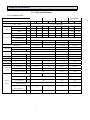
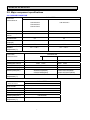
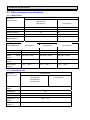
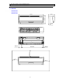
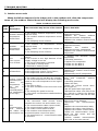
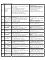
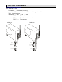
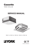
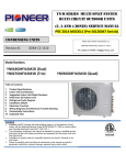
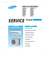
1
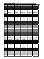
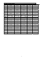
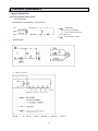
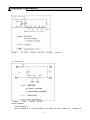
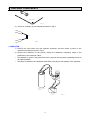
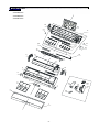
MULTI-SPLIT TYPE AIR CONDITONER
SERVICE MANUAL
●INDOOR
UNIT:
V:4.0
AMS-07UR4SNVG4(VT、VL、VQ、UP、UL、UQ、NS、ZC、ZA)4
AMS-09UR4SNVG4(VT、VL、VQ、UP、UL、UQ、NS、ZC、ZA)4
AMS-12UR4SNVG4(VT、VL、VQ、UP、UL、UQ、NS、ZC、ZA)4
AMS-18UR4SVUP3(VG3、VL3、VT3、UP3、UL3、UQ3)
AMD-09UX4SJD
AMD-12UX4SJD
AMD-18UX4SJD
AMC-12UX4SAA
AMC-18UX4SAA
SSH-PM074DC
SSH-PM094DC
SSH-PM124DC
SSH-PM184DC
●OUTDOOR UNIT:
AMW2-16U4SGC1
AMW2-20U4SNC1
AMW3-20U4SZD
AMW3-24U4SZD
AMW3-24U4SKC
AMW4-28U4SKC
AMW4-36U4SAC
SRH-PM18DC
SRH-PM24DC
SRH-PM36DC
Hisense Corporation
Table of contents
Page
1.OPERATING RANGE
1
2.SPECIFICATION
2
2-1 Unit specifications
2
2-2 Major component specifications
7
2-3 Other component specifications
9
3.OUTLINES AND DIMENSIONS
10
3-1 INDOOR
10
3-2 OUTDOOR
14
4.REFRIGERANT FLOW DIAGRAM
17
4-1 Refrigerant flow diagram
17
4-2 Evacuation procedures
20
4-3 Evacuation direction
21
5.ELECTRICAL DATA
22
5-1 Electric wiring diagrams
22
5-2 Electric control
33
5-3 Sensor parameter
40
6.CONTROL MODE
48
6-1 Indoor control mode
48
6-2 Outdoor control mode
51
7.TROUBLESHOOTING
54
7-1 Error codes
54
8.CHECKING COMPONENTS
56
8-1 Check refrigerant system
56
8-2 Check parts unit
58
9.PARTS LIST
58
9-1 Indoor
64
9-2 Outdoor
76
1. OPERATING RANGE
COOLING
HEATING
Temperature
Indoor Air Intake Temp.
Outdoor Air Intake Temp
Maximum
32℃ D.B./23℃ W.B.
43 ℃ D.B./26℃ W.B.
Minimum
21℃ D.B./15℃ W.B.
21 ℃ D.B./15℃ W.B.
Maximum
27℃ D.B./18℃ W.B.
24℃ D.B./18℃ W.B.
Minimum
20℃ D.B/≤15℃ W.B
-7℃ D.B./-8℃ W.B.
1
2. SPECIFICATIONS
2-1. Unit specifications
2-1-1.OUTDOOR UNIT
Model
AMW4-28U4SKC
Function
Power
Capacity
Electrical data
Cooling
AMW2-16U4SGC1
SRH-PM18DC
Cooling
Cooling
Heating
Cooling
Heating
Heating
a.c
220V~240V/50Hz
Capacity
kW
8.2
9.0
7.0
8.0
5.8
6.4
4.6
5.3
Dehumidification
l /h
----
----
----
----
----
----
----
----
Air flow
3
m /h
----
----
----
----
----
----
2400
2400
Rated current
A
10.7
11.1
9.7
10.1
7.7
8.0
6.1
5.7
Rated input
kW
2.4
2.49
2.18
2.21
1.7
1.75
1.4
1.3
Auxiliary heater
A
Power factor
%
99.9%
99.9%
99.9%
99.9%
Max. current
A
15.0
15.0
14.5
10.0
3.42/.362
3.21/3.62
3.41/3.66
3.29/4.08
ATL165SD-C9AU
DA130S1C-20FZ
DA130S1C-20FZ
0.590 (at75℃)
0.95(20℃)
0.95(20℃)
YDK70-6H-3
YDK55-6I-8
YDK29-6I-22
------
Model
Winding resistance
Outdoor
AMW2-20U4SNC1
supply
EER/CPOP
Compressor
Heating
AMW3-24U4SKC
Ω
Model
fan motor
Winding resistance (at20℃)
Ω
M:78;A:80
M:185;A:200
M:283.5;A:180
Net size
L×W×H
cm
109×41×84
98×35×64
80×26×57
L×W×H
cm
112×46×98
108×42×72
94×36×64
Package size
Net weight
kg
67
66
46.5
36.5
Gross weight
kg
77
76
52.5
40
Liquid pipe
mm
6.35×4
6.35×3
6.35×2
6.35×2
Gas pipe
mm
9.52×4
9.52×3
9.52×2
9.52×2
Flare
Flare
----
----
Refrigerant
piping
Connection method
Flare
Air direction
Special
remarks
----
----
Sound level (Hi)
dB
57
57
48
Fan speed (Hi)
rpm
840
840
900
3
3
3
Fan speed regulator
Refrigerant filling
capacity(R410a)
Throttle mode
kg
2.4
2.1
1.4
1.27
EEV
EEV
EEV
EEV
2
2. SPECIFICATIONS
Model
Function
Power
Capacity
Electrical data
Cooling
Cooling
a.c
SHR-PM36DC
AMW4-36U4SAC
Heating
Coolng
Heating
220V~240V/50Hz
Capacity
kW
6.0
7.0
7
7.8
10
1.1
Dehumidification
l /h
----
----
----
----
----
----
Air flow
m3/h
----
----
3200
3200
4200
4200
Rated current
A
8.55
8.58
10.0
9.5
14.5
14.0
Rated input
kW
1.87
1.9
2.18
2.1
3.1
3.04
Auxiliary heater
A
Power factor
%
99.9%
99.9%
99.9%
Max. current
A
13.5
15.5
22.0
3.21/3.70
3.21/3.71
3.22/3.62
------
Model
Winding resistance
Outdoor
Heating
supply
EER/COP
Compressor
SRH-PM24DC
AMW3-24U4SZD
AMW3-20U4SZD
ATL165SD-C9AU
ATL232SJNC9AU
0.590 (at75℃)
0.95(20℃)
Ω
Model
YDK55-6I-8
YDK70-6H-3
M:185;A:200
M:78;A:80
YDK95-6-9043
fan motor
Winding resistance (at20℃)
Ω
Net size
L×W×H
cm
98×35×64
109×41×84
L×W×H
cm
108×42×72
111×46×98
Package size
M:59.1;A:85.8
Net weight
kg
52
53
67
Gross weight
kg
56
57
77
Liquid pipe
mm
6.35×3
6.35×3
6.35×4
Gas pipe
mm
9.52×3
9.52×3
9.52×4
Refrigerant
piping
Connection method
Flare
Air direction
Special
remarks
----
Flare
----
----
Sound level (Hi)
dB
53
57
Fan speed (Hi)
rpm
840
800
3
3
Fan speed regulator
Refrigerant filling
capacity(R410a)
kg
Throttle mode
NOTE :Test conditions:
Cooling : Indoor: DB27℃/ WB19℃
Heating: Indoor: DB20℃/ WB15℃
1.6
1.75
2.6
EEV
EEV
EEV
Outdoor: DB35℃/ WB24℃
Outdoor: DB7℃/ WB 6℃
3
2. SPECIFICATIONS
2-1-2.INDOOR UNIT
AMS-07UR4SNVG4
AMS-12UR4SNVG4
AMS-09UR4SNVG
(VT4、VL4、VQ4、
AMS-18UR4SVVG3
SSH-PM074DC
SSH-PM124DC
SSH-PM184DC
UP4、UL4、UQ4、
(VT4、VL4、VQ4、
(VL3/VT3/UP3/
SSH-PM094DC
NS4、ZC4、ZA4)
UP4、UL4、UQ4、NS4、
UL3/UQ3)
ZC4、ZA4)
Model
Function
Power
Cooling
supply
Cooling
a.c
Capacity
kW
2.1/2.6
Dehumidification
l /h
0.8
Air flow
m /h
Running current
2.5/3.0
Indoor
fan motor
Outdoor
fan motor
Net size
Package size
Cooling
Heating
220V~240V/50Hz
3.7
5.0
5.5
----
0.8
----
1.5
----
400
520
450
560
800
900
A
0.2
0.2
0.2
0.2
0.4
0.4
Rated input
kW
0.04
0.04
0.04
0.04
0.085
0.085
Auxiliary heater
A
----
Power factor
%
----
Starting current
A
----
3
EER/COP
Compressor
Heating
3.2
Capacity
Electrical data
Heating
----
Model
----
Winding resistance (at25℃) Ω
----
Model
Winding resistance (at20℃) Ω
YYW16-4-532
RPG25A-6
M:364;A:400.5;
M:211.2;A:211;
Model
----
Winding resistance (at20
Ω
℃)
L×W×H
cm
L×W×H
cm
---75×25×19
75×25×19
80×31×25(VQ:8880×31×25(VQ:88×
×33×26)
33×26)
92×31.3×22.6
100.7×38×29.7
Net weight
kg
7.5
7.5
11.5
Gross weight
kg
9.0
9.0
14.0
Liquid pipe
mm
6.35
6.35
6.35
Gas pipe
mm
9.52
9.52
9.52
Refrigerant
piping
Connection method
----
Air direction
Special
remarks
6
6
6
Sound level (Hi)
dB
24/27
30
32
Fan speed (Hi)
rpm
1150
1250
1300
3
3
3
Fan speed regulator
Refrigerant filling
capacity(R410a)
kg
----
Throttle mode
---4
2. SPECIFICATIONS
2-2. Major component specifications
2-2-1.INDOOR FAN MOTOR
PARAMETER
ELECTRIC
PERFOMANCE
SSH-PM074DC
SSH-PM094DC
SSH-PM124DC
Motor model
Rated
source
SSH-PM184DC
RPG25A-6
YYW16-4-532
power
220V
Phases/Poles
Rated
output(W)
load
Rated speed(r/min)
Ambient
temperature(℃)
50Hz
220V 50HZ
1/4
1/4
18
25
1250
1270
-5℃~+43℃.
-5℃~+43℃.
ELECTRIC
PERFOMANCE
PARAMETER
Motor model
YSK95-25-4HS10
Rated power source
220V
50Hz
YSK95-40-4HS11
220V
Phases/Poles
1/4
1/4
Rated load output(W)
25
42
Rated speed(r/min)
980/850/700(White)
1150/1070/980(Red)
-5℃~+43℃.
Ambient
temperature(℃)
ELECTRIC
PERFOMANCE
PARAMETER
YDK95-28-4-B
Motor model
Rated power source
220V
Phases/Poles
1/4
Rated load output(W)
25
50Hz
Rated speed(r/min)
Ambient
temperature(℃)
720/840/980
-5℃~+43℃.
7
50Hz
1360/1300/1240(Red)
1240/1155/1050 (White)
-5℃~+43℃
2. SPECIFICATIONS
2-2-2 OUTDOOR FAN MOTOR
PARAMETER
ELECTRIC
PERFOMANCE
SRH-PM24DC
SRH-PM36DC
Motor model
YDK70-6H-3
YDK95-6-9043
Rated power source
220V
Phases /Poles
Rated
output(W)
Ambient
load
50Hz
220V
SRH-PM18DC
50Hz
YDK55-6I-8
YDK29-6I-22
220V
220V
50Hz
50Hz
1/6
1/6
1/6
1/6
65
95
50
29
-5℃~+43℃
-5℃~+50℃
-5℃~+43℃
-5℃~+43℃
temperature (℃)
2-3. COMPRESSOR
PARAMETER
ELECTRIC
PERFOMANCE
SRH-PM36DC
SRH-PM18DC
ATL165SD-C9AU
ATL232SJNC9AU
DA130S1C-20FZ
Compressor type
Rotary
Rotary
Rotary
Rated power
1550W
2000W
990W
10.7
11.2
4.97
DC brushless motor
DC brushless
motor
DC brushless motor
DC Inverter
DC Inverter
DC Inverter
0.59/0.59/0.59Ω(at
75℃)
U-V/V-W/W-U
0.82/0.82/0.82Ω(at
75℃)
U-V/V-W/W-U
0.95/0.95/0.95Ω(at 20
℃)
U-V/V-W/W-U
2
2
2
α68HES-H or
equivalent
HAF68D1C
ESTER OIL VG74
880
880
500
-5℃~+43℃.
-5℃~+43℃
-5℃~+43℃
Compressor model
Current (A)
Motor
Motor type
Starting type
Winding
resistance
Number of cylinder
Oil type
Oil charge (cc)
Ambient temperature(℃)
8
2. SPECIFICATIONS
2-3. Other component specifications
2-3-1. INDUCTANCE
PARAMETER
ELECTRIC
PERFOMANCE
SRH-PM24DC
SRH-PM36DC
Inductance model
SRH-PM18DC
R2550HSA
Rated power source
220V
R2050HSB
50Hz
220V
50Hz
Rated current(A)
25
20
Rated inductance
5.0(mH)±10%
5.2(mH)±10%
Ambient
temperature(℃)
-20℃~+70℃.
-20℃~+70℃.
2-3-2. FILTER
ELECTRIC
PERFORMANCE
AMW3-24U4SKC
AMW4-28U4SKC
SRH-PM24DC
AMW3-24U4SZD
AMW3-20U4SZD
SRH-PM36DC
AMW4-36U4SAC
AMW2-20U4SNC
AMW2-16U4SGC
SRH-PM18DC
Filter model
RTNF-250T10X-3LF
RTNF250-30T10X-3LF
RTNF250-25T068X-03LF
Rated current(A)
20
30
20
Rated
source
AC 220V—50Hz
AC 220V—50Hz
AC 220V—50Hz
150K—30MHz
150K—30MHz
150K—30MHz
-25℃~+85℃.
-25℃~+85℃.
-25℃~+85℃.
Filter
range
power
frequency
Temperature
range(℃)
2-3-4. STEPPER MOTOR
PARAMETER
ELECTRIC
PERFOMANCE
Stepper
model
SSH-PM074DC
SSH-PM094DC
SSH-PM124DC
Motor
24BYJ48
Voltage(DC)
12V
Number of phase
Drive mode
Resistance
phase
SSH-PM184DC
4
1-2phase excitation unipolar drive
300Ω±7%
per
-10℃~+40℃
Temperature
range(℃)
9
3. OUTLINES AND DIMENSIO
3-1. INDOOR
(MODEL:
AMS-07UR4SNVG4 AMS-09UR4SNVG AMS-12UR4SNVG4(VT4、VL4、
SSH-PM074DC
VQ4、UP4、UL4、UQ4、NS4、ZC4、ZA4)
SSH-PM094DC
SSH-PM124DC
190mm
250mm
750mm
65mm
94mm
23mm
50mm
631mm
50mm
50mm
10
3. OUTLINES AND DIMENSIO
3-2.OUTDOOR
(MODEL: AMW2-16U4SGC1)
SRH-PM18DC
14
3. OUTLINES AND DIMENSIO
SRH-PM24DC
(MODEL: AMW2-20U4SNC1、 AMW3-20U4SZD 、AMW3-24U4SZD)
15
3. OUTLINES AND DIMENSIO
SRH-PM36DC
(MODEL: AMW3-24U4SKC、AMW4-28U4SKC
16
AMW4-36U4SAC)
4. REFRIGERANT FLOW DIAGRAM
4-1.
Refrigerant flow diagram :
MODEL:AMW3-24U4SKC、AMW4-28U4SKC、AMW4-36U4SAC
SRH-PM36DC
A机
B机
C机
D机
D机
C机
B机
Filter
A机
Remark:
SRH-PM36DC
The part is only for AMW4-28U4SKC、AMW4-36U4SAC
COOLING CYCLE
HEATING CYCLE
17
4. REFRIGERANT FLOW DIAGRAM
SRH-PM24DC 、AMW3-20U4SZD
MODEL:AMW3-24U4SZD
COOLING CYCLE
HEATING CYCLE
18
4. REFRIGERANT FLOW DIAGRAM
MODEL:SRH-PM18DC
AMW2-16U4SGC1、AMW2-20U4SNC1
4-way valve
A机
B机
B机
EEV B Filter
A机
EEV A Filter
19
4. REFRIGERANT FLOW DIAGRAM
4.2 Evacuation procedures:
EVACUATION PROCEDURES
Connect the refrigerant pipes (both the liquid and
gas pipes) between the indoor and the outdoor units.
Remove service port cap of the stop valve A and connect gage manifold valve and vacuum
pump to it.
Run the vacuum pump for more than 15 minutes and at this time confirm that the pressure
gage indicates -0.1Mpa(-76 cmHg).
Stop pump and keep the pressure for one or two minutes. Make sure the pressure is no
change(if the pressure is changed to high, there is some leakage for the pipe connection).
Remove gage manifold valve quickly from the service port of the stop valve A.
full open the stop valves A on gas and liquid pipe sides.
Repeat the steps above for other valves(B\C\D), be sure all refrigerant pipes are
connected and evacuated, and all valves are full opend.
Total pipe length is in the range:
No gas charge is needed
Total pipe length exceeding the limit:
Charge the prescribed amount of gas.
Tighten the cap to the service port to obtain the initial status.
Retighten the cap.
Leak test
20
4. REFRIGERANT FLOW DIAGRAM
4-3.
Evacuation direction:
MAX. Refrigerant pipe length and height difference:
AMW3-20U4SZD
AMW3-24U4SZD
SRH-PM24DC
Modle
AMW3-24U4SKC
SRH-PM36DC
AMW4-28U4SKC
AMW2-20U4SNC1
SRH-PM18DC
AMW2-16U4SGC1
AMW4-36U4SAC
Pipe length per. Indoor unit(a/b/c/d)
25m
20m
Total pipe length for multi-system (a+b+c+d)
60m
40m
Height difference (I.D ~ O.D)
15m
15m
Height difference (I.D ~ I.D)
7.5m
7.5m
*Do your best to reduce the pipe length. Long pipe may cause capacity of the indoor unit incline.
Outdoor unit precharged
Total refrigerant pipe length
0m~20m
AMW3-24U4SKC
2100g
0g
AMW4-28U4SKC
SRH-PM36DC
AMW4-36U4SAC
2400g
0g
2600g
0g
SRH-PM24DC
AMW3-24U4SZD
1750g
0g
AMW3-20U4SZD
1600g
0g
Outdoor unit precharged
AMW2-20U4SNC1
SRH-PM18DC
AMW2-16U4SGC1
1400g
1270g
20m~60m
Xg = 15g / m × (Total pipe length(m) - 20)
If gas pipe include 12.7,refrigerant piping
length 20g/m
Total refrigerant pipe length
0m~15m
15m~40m
0
Xg = 15g / m × (Total pipe length(m) - 15)
21
5. ELECTRICAL DATA
5-1.Electrical wiring diagrams
INDOOR:
1) AMS-07UR4SNVG4(VT、VL、VQ、UP、UL、UQ、NS、ZC、ZA)4
SSH-PM074DC
SSH-PM094DC
AMS-09UR4SNVG4(VT、VL、VQ、UP、UL、UQ、NS、ZC、ZA)4
SSH-PM124DC
AMS-12UR4SNVG4(VT、VL、VQ、UP、UL、UQ、NS、ZC、ZA)4
22
5. ELECTRICAL DATA
2) AMS-18UR4SVUP3(VG3、VL3、VT3、UP3、UL3、UQ3)
SSH-PM184DC
23
5. ELECTRICAL DATA
OUTDOOR: SRH-PM18DC
1)AMW2-16U4SGC1
26
5. ELECTRICAL DATA
4)AMW3-24U4SZD
SRH-PM24DC
29
5. ELECTRICAL DATA
SRH-PM36DC
7)AMW4-36U4SAC
32
5. ELECTRICAL DATA
5-2. Electric control
1. Indoor control board for indoor unit
1)AMS-07UR4SNVG4
AMS-09UR4SNVG AMS-12UR4SNVG4(VT4、VL4、VQ4、UP4、UL4、UQ4、
SSH-PM074DC
SSH-PM094DC
NS4、ZC4、ZA4)
SSH-PM124DC
AC N
3.15A/250V
10A-HEAT
AC L
Communication Signal
Display
feed back
Louver motor
Pipe temperature
Room temperature
33
Fan motor
5. ELECTRICAL DATA
2) AMS-18UR4SVVG3 (VL3/VT3/UP3/UL3/UQ3)
SSH-PM184DC
Communication Signal
Fan motor feedback
Louver motor
Display
Pipe temperature
Roomtemperature
Transformer in
AC NIN
AC L IN
Transformer out
34
5. ELECTRICAL DATA
3) AMD-09UX4SJD、AMD-12UX4SD、AMD-18UX4SJD
Pump motor
Transformer
Fan protector
AC fan motor
Fan N line
Step motor
AC N IN
AC L IN
Communication
Transformer
Outside input
Water level
switch
To display
board
Wiring remote
controller
Room
sensor
Coil
sensor
TEST
4) AMC-12UX4SAA、AMC-18UX4SAA
Fan motor
Pump motor
Room Coil
Test sensor sensor
Communication
signal
Water level
switch
Wiring remote
controller
Transformer
AC N IN
Step motor
AC L IN
Outside input
To display board
Transformer
2.Control board for outdoor unit
1)FILTER BOARD (AMW3-24U4SKC、AMW4-28U4SKC
AMW4-36U4SAC )
SRH-PM36DC
To Indoor N
AC N OUT
AC N IN
AC L IN
To Indoor L
To Control Board
GND
AC L OUT
+12V
3.15 /250
4-Way Drving
Fan Motor Drving
Heater N out
Heater L out
35
5. ELECTRICAL DATA
2)CONTROL BOARD(AMW3-24U4SKC、AMW4-28U4SKC
AMW4-36U4SAC )
SRH-PM36DC
DC in
IPM
POWER
To IPM
Board
To Filter
Board
Communication
Signal D
Communication
Signal N
Communication
Signal C
Communication
Signal B
Communication
Signal A
Overload
Protection
D Valve
Drving
C Valve B Valve
Drving Drving
A Valve
Drving
Outdoor/ Liquid
Gas
Defrose
Sensor
Suction/ Pipe A/B/C A/B/C
Liquid
Pipe
Sensor
Condensor Sensor
D Sensor
Sensor
Compressor Discharge Sensor
Gas D Sensor
High Pressure Protection
AMW3-24U4SZD)
CONTROL BOARD(AMW3-20U4SZD
SRH-PM24DC
Fan motor
Heater N
N OUT
AC N IN
4-way valve
AC L IN
Heater L
Communication
signal A
Communication
signal B
Communication
signal C
IPM power
Communication
signal N
Electric expansion valve C
DC+ in
High pressure
switch
DC- in
Electric expansion valve A
Electric expansion valve B
Defrost sensor
Discharge sensor
36
Gas A/B/C sensor
Liquid pipe A/B/C sensor
Outdoor/suction/coil sensor
5. ELECTRICAL DATA
CONTROL BOARD(AMW2-16U4SGC1
AMW2-20U4SNC1)
SRH-PM24DC
AC Fan Motor
SRH-PM36DC
AC N OUT AC L OUT
AC N IN
Earth Wire
AC L IN
4-Way Valve
TO Indoor unit A
TO Indoor unit B
To IPM Board
(Communication)
Communication N
To IPM Board
(Power)
Overload
Protection
DCDC+
B VALVE
DRVING
Outdoor/Suction/
Condensor Sensor
Gas B Sensor
Compressor
Discharge Sensor
Liquid A/B &
A VALVE DRVING
Gas A Sensor
37
5. ELECTRICAL DATA
3)IPM BOARD
(AMW3-24U4SKC、AMW4-28U4SKC
SRH-PM24DC
AMW4-36U4SAC AMW3-20U4SZD
SRH-PM26DC
To PFC
Inductor-2
To PFC
Inductor-1
To Electrolytic
Capacitor +
ac L in
ac N in
To Electrolytic
Capacitor IPM Power
To Compressor W
To Compressor V
To Compressor U
To Electrolytic
Capacitor +
To Main Control
Board
38
AMW3-24U4SZD)
5. ELECTRICAL DATA
IPM Board(AMW2-16U4SGC1
AMW2-20U4SNC1)
SRH-PM18DC
To Electrolytic
Capacitor +
To PFC Inductor-2
AC L IN
To PFC Inductor-1
To Electrolytic
Capacitor AC N IN
IPM Power
To Compressor W
To Compressor V
To Compressor U
To Main Control
Board
To Electrolytic
Capacitor +
39
5. ELECTRICAL DATA
5-3. Sensor parameter
1. THE PARAMETER OF OUTDOOR COMPRESSOR DISCHARGE TEMPERATURE SENSOR:
(R0=187.25K±6.3%;R100=3.77K±2.5K;B0/100=3979K±1%)
T[ ℃ ]
-30
-29
-28
-27
-26
-25
-24
-23
-22
-21
-20
-19
-18
-17
-16
-15
-14
-13
-12
-11
-10
-9
-8
-7
-6
-5
-4
-3
-2
-1
0
1
2
3
4
5
6
7
8
9
Rmin [ KΩ ]
908.2603
855.3955
805.9244
759.6097
716.2320
675.5881
637.4902
601.7645
568.2499
536.7970
507.2676
497.5332
453.4748
428.9819
405.9517
384.2888
363.9047
344.7169
326.6497
309.6286
293.5903
278.4719
264.2156
250.7678
238.0783
226.1003
214.7903
204.1073
194.0135
184.4732
175.4533
166.8952
158.8023
151.1467
143.9026
137.0455
130.5528
124.4033
118.5769
113.0550
Rnom [ KΩ ]
985.5274
927.6043
873.4324
822.7471
775.3041
730.8775
689.2583
650.2533
613.6835
579.3832
547.1989
516.9882
488.6192
461.9693
436.9251
413.3808
391.2386
370.4072
350.8019
332.3441
314.9620
298.5822
283.1464
268.5936
254.8686
241.9200
229.6997
218.1630
207.2681
196.9759
187.2500
178.0255
169.3067
161.0633
153.2667
145.8905
138.9097
132.3011
126.0429
120.1146
Rmax [ KΩ ]
1065.1210
1001.9150
924.8368
887.5944
835.9165
787.5529
742.2720
699.8601
660.1191
622.8658
587.9307
555.1565
524.3977
495.5191
486.3954
442.9105
418.9563
396.4325
375.2461
355.3104
336.5448
318.3744
302.2294
286.5448
271.7603
257.8193
244.6593
232.2612
220.5495
209.4913
199.0468
189.1529
179.8058
170.9724
162.6216
154.7246
147.2544
140.1856
133.4946
127.1591
40
DR(MIN)%
-7.84
-7.78
-7.73
-7.67
-7.62
-7.56
-7.51
-7.46
-7.40
-7.35
-7.30
-3.76
-7.19
-7.14
-7.09
-7.04
-6.99
-6.94
-6.88
-6.83
-6.79
-6.74
-6.69
-6.64
-6.59
-6.54
-6.49
-6.44
-6.39
-6.35
-6.30
-6.25
-6.20
-6.16
-6.11
-6.06
-6.02
-5.97
-5.92
-5.88
DR(MAX)%
7.47
7.42
5.56
7.31
7.25
7.20
7.14
7.09
7.03
6.98
6.93
6.88
6.82
6.77
10.17
6.67
6.62
6.56
6.51
6.46
6.41
6.22
6.31
6.26
6.22
6.17
6.11
6.07
6.02
5.97
5.93
5.88
5.84
5.80
5.75
5.71
5.67
5.62
5.58
5.54
5. ELECTRICAL DATA
10
11
12
T[ ℃ ]
13
14
15
16
17
18
19
20
21
22
23
24
25
26
27
28
29
30
31
32
33
34
35
36
37
38
39
40
41
42
43
44
45
46
47
48
49
50
51
52
53
107.8202
102.8560
98.1470
Rmin [ KΩ ]
93.6787
89.4378
85.4114
81.5875
77.9551
74.5034
71.2227
68.1036
65.1373
62.3155
59.6306
57.0752
54.6424
52.3258
50.1192
48.0168
46.0133
44.1034
42.2825
40.5458
38.8891
37.3084
35.7998
34.3596
32.9844
31.6710
30.4164
29.2176
28.0718
26.9765
25.9293
24.9277
23.9697
23.0530
22.1757
21.3360
20.5321
19.7623
19.0261
18.3211
17.6458
114.4973
109.1728
104.1246
Rnom [ KΩ ]
99.3367
94.7946
90.4842
86.3926
82.5076
78.8177
75.3122
71.9808
68.8141
65.8032
62.9395
60.2152
57.6227
55.1551
52.8058
50.5684
48.4371
46.4046
44.4711
42.6261
40.8668
39.1890
37.5883
36.0609
34.6030
33.2113
31.8823
30.6130
29.4004
28.2417
27.1342
26.0755
25.0632
24.0950
23.1688
22.2826
21.4345
20.6226
19.8468
19.1040
18.3926
121.1586
115.4734
110.0855
Rmax [ KΩ ]
104.9778
100.1342
95.5398
91.1805
87.0430
83.1150
79.3848
75.8414
72.4746
69.2746
66.2324
63.3395
60.5877
57.9695
55.4778
53.1058
50.8472
48.6960
46.6466
44.6937
42.8323
41.0576
39.3653
37.7511
36.2109
34.7412
33.3383
31.9988
30.7197
29.4979
28.3306
27.2150
26.1488
25.1293
24.1545
23.2221
22.3301
21.4766
20.6612
19.8808
19.1338
41
-5.83
-5.79
-5.74
DR(MIN)%
-5.70
-5.65
-5.61
-5.56
-5.52
-5.47
-5.43
-5.39
-5.34
-5.30
-5.26
-5.21
-5.17
-5.13
-5.09
-5.05
-5.00
-4.96
-4.92
-4.88
-4.84
-4.80
-4.76
-4.72
-4.68
-4.64
-4.60
-4.56
-4.52
-4.48
-4.44
-4.40
-4.36
-4.32
-4.29
-4.25
-4.21
-4.17
-4.14
-4.10
-4.06
5.50
5.46
5.41
DR(MAX)%
5.37
5.33
5.29
5.25
5.21
5.17
5.13
5.09
5.05
5.01
4.97
4.93
4.89
4.85
4.82
4.78
4.74
4.71
4.66
4.63
4.59
4.55
4.51
4.48
4.44
4.40
4.37
4.33
4.29
4.26
4.22
4.19
4.15
4.12
4.08
4.05
4.01
3.98
3.94
3.91
3.87
5. ELECTRICAL DATA
54
55
56
57
58
59
T[ ℃ ]
60
61
62
63
64
65
66
67
68
69
70
71
72
73
74
75
76
77
78
79
80
81
82
83
84
85
86
87
88
89
90
91
92
93
94
95
96
97
16.9986
16.3784
15.7839
15.2139
14.6673
14.1430
Rmin [ KΩ ]
13.6400
13.1573
12.6941
12.2494
11.8224
11.4124
11.0185
10.6401
10.2765
9.9271
9.5912
9.2682
8.9576
8.6589
8.3716
8.0951
7.8290
7.5730
7.3264
7.0891
6.8605
6.6403
6.4282
6.2239
6.0269
5.8371
5.6542
5.4777
5.3076
5.1435
4.9853
4.8326
4.6852
4.5430
4.4058
4.2733
4.1453
4.0218
17.7113
17.0537
16.4332
15.8338
15.2592
14.7083
Rnom [ KΩ ]
14.1799
13.6730
13.1868
12.7202
12.2723
11.8424
11.4295
11.0331
10.6522
10.2863
9.9348
9.5968
9.2720
8.9597
8.6594
8.3705
8.0926
7.8252
7.5679
7.3202
7.0818
6.8522
6.6311
6.4182
6.2131
6.0154
5.8249
5.6413
5.4644
5.2937
5.1292
4.9705
4.8174
4.6697
4.5272
4.3896
4.2568
4.1287
18.4185
17.7335
17.0774
16.4488
15.8464
15.2690
Rmax [ KΩ ]
14.7154
14.1846
13.6756
13.1872
12.7186
12.2690
11.8373
11.4230
11.0251
10.6429
10.2756
9.9231
9.5841
9.2583
8.9451
8.6440
8.3544
8.0758
7.8078
7.5499
7.3018
7.0629
6.8329
6.6115
6.3982
6.1928
5.9949
5.8042
5.6205
5.4433
5.2726
5.1079
4.9492
4.7960
4.6483
4.5058
4.3683
4.2355
42
-4.02
-3.96
-3.95
-3.92
-3.88
-3.84
DR(MIN)%
-3.81
-3.77
-3.74
-3.70
-3.67
-3.63
-3.60
-3.56
-3.53
-3.49
-3.46
-3.42
-3.39
-3.36
-3.32
-3.29
-3.26
-3.22
-3.19
-3.16
-3.12
-3.09
-3.06
-3.03
-3.00
-2.96
-2.93
-2.90
-2.87
-2.84
-2.81
-2.77
-2.74
-2.71
-2.68
-2.65
-2.62
-2.59
3.84
3.83
3.77
3.74
3.71
3.67
DR(MAX)%
3.64
3.61
3.57
3.54
3.51
3.48
3.45
3.41
3.38
3.35
3.32
3.29
3.26
3.23
3.19
3.16
3.13
3.10
3.07
3.04
3.01
2.98
2.95
2.92
2.89
2.86
2.84
2.81
2.78
2.75
2.72
2.69
2.66
2.63
2.61
2.58
2.55
2.52
5. ELECTRICAL DATA
98
99
100
101
102
103
104
105
106
107
108
109
110
111
112
113
114
115
116
117
118
119
120
121
122
123
124
125
126
127
128
129
130
3.9024
3.7872
3.6758
3.5661
3.4601
3.3577
3.2588
3.1632
3.0708
2.9816
2.8953
2.8118
2.7311
2.6531
2.5776
2.5046
2.4340
2.3656
2.2995
2.2354
2.1734
2.1134
2.0553
1.9991
1.9446
1.8918
1.8406
1.7911
1.7430
1.6965
1.6514
1.6076
1.5652
4.0049
3.8854
3.7700
3.6585
3.5509
3.4468
3.3463
3.2491
3.1551
3.0643
2.9765
2.8915
2.8093
2.7299
2.6530
2.5785
2.5065
2.4368
2.3693
2.3040
2.2407
2.1795
2.1201
2.0626
2.0070
1.9530
1.9007
1.8500
1.8009
1.7533
1.7071
1.6623
1.6189
4.1074
3.9837
3.8643
3.7512
3.6419
3.5362
3.4341
3.3353
3.2398
3.1475
3.0582
2.9717
2.8881
2.8072
2.7289
2.6531
2.5798
2.5087
2.4400
2.3733
2.3088
2.2463
2.1858
2.1271
2.0702
2.0151
1.9617
1.9099
1.8597
1.8110
1.7638
1.7180
1.6736
43
-2.56
-2.53
-2.50
-2.53
-2.56
-2.59
-2.61
-2.64
-2.67
-2.70
-2.73
-2.76
-2.78
-2.81
-2.84
-2.87
-2.89
-2.92
-2.95
-2.98
-3.00
-3.03
-3.06
-3.08
-3.11
-3.13
-3.16
-3.18
-3.22
-3.24
-3.26
-3.29
-3.32
2.50
2.47
2.44
2.47
2.50
2.53
2.56
2.58
2.61
2.64
2.67
2.70
2.73
2.75
2.78
2.81
2.84
2.87
2.90
2.92
2.95
2.97
3.01
3.03
3.05
3.08
3.11
3.14
3.16
3.19
3.21
3.24
3.27
5. ELECTRICAL DATA
2. THE PARAMETER OF THE OTHER SENSOR IN INDOOR AND OUTDOOR UNIT:
(R0=15K±2%;
B0/100=3450K±2%)
T
[ ℃ ]
-30
-29
-28
-27
-26
-25
-24
-23
-22
-21
-20
-19
-18
-17
-16
-15
-14
-13
-12
-11
-10
-9
-8
-7
-6
-5
-4
-3
-2
-1
0
1
2
3
4
5
6
7
8
9
10
Rmin [ KΩ ]
Rnom [ KΩ ]
Rmax [ KΩ ]
60.78
57.75
54.89
52.19
49.63
47.21
44.92
42.76
40.71
38.77
36.93
35.18
33.53
31.96
30.48
29.07
27.73
26.46
25.26
24.11
23.03
21.99
21.01
20.08
19.19
18.35
17.55
16.78
16.06
15.36
14.70
14.08
13.48
12.91
12.36
11.85
11.35
10.88
10.43
9.999
9.590
64.77
61.36
58.15
55.14
52.30
49.62
47.10
44.73
42.49
40.38
38.39
36.51
34.74
33.06
31.47
29.97
28.56
27.22
25.95
24.75
23.61
22.53
21.51
20.54
19.62
18.74
17.92
17.13
16.38
15.67
15.00
14.36
13.75
13.17
12.62
12.09
11.59
11.11
10.66
10.230
9.816
68.99
65.16
61.58
58.23
55.08
52.13
49.37
46.78
44.34
42.05
39.90
37.87
35.97
34.17
32.49
30.89
29.39
27.98
26.64
25.38
24.19
23.06
22.00
20.99
20.04
19.14
18.29
17.48
16.71
15.98
15.29
14.64
14.02
13.43
12.87
12.34
11.83
11.35
10.89
10.450
10.040
44
DR(MIN)% DR(MAX)%
-6.16
-5.88
-5.61
-5.35
-5.11
-4.86
-4.63
-4.40
-4.19
-3.99
-3.80
-3.64
-3.48
-3.33
-3.15
-3.00
-2.91
-2.79
-2.66
-2.59
-2.46
-2.40
-2.32
-2.24
-2.19
-2.08
-2.06
-2.04
-1.95
-1.98
-2.00
-1.95
-1.96
-1.97
-2.06
-1.99
-2.07
-2.07
-2.16
-2.26
-2.30
6.12
5.83
5.57
5.31
5.05
4.81
4.60
4.38
4.17
3.97
3.78
3.59
3.42
3.25
3.14
2.98
2.82
2.72
2.59
2.48
2.40
2.30
2.23
2.14
2.10
2.09
2.02
2.00
1.97
1.94
1.90
1.91
1.93
1.94
1.94
2.03
2.03
2.11
2.11
2.11
2.23
5. ELECTRICAL DATA
11
12
T
[ ℃ ]
13
14
15
16
17
18
19
20
21
22
23
24
25
26
27
28
29
30
31
32
33
34
35
36
37
38
39
40
41
42
43
44
45
46
47
48
49
50
51
52
53
9.199
8.826
9.422
9.047
9.647
9.269
-2.37
-2.44
2.33
2.40
Rmin [ KΩ ]
Rnom [ KΩ ]
Rmax [ KΩ ]
DR(MIN)
DR(MAX)
8.470
8.129
7.804
7.493
7.196
6.912
6.640
6.381
6.132
5.894
5.667
5.449
5.240
5.048
4.864
4.687
4.517
4.355
4.198
4.048
3.904
3.766
3.663
3.506
3.383
3.265
3.152
3.043
2.938
2.838
2.741
2.648
2.558
2.472
2.389
2.309
2.232
2.158
2.087
2.018
1.952
8.689
8.347
8.021
7.709
7.412
7.127
6.855
6.595
6.347
6.109
5.882
5.664
5.456
5.260
5.072
4.891
4.717
4.550
4.390
4.236
4.089
3.946
3.810
3.679
3.552
3.431
3.314
3.202
3.094
2.990
2.890
2.793
2.701
2.611
2.525
2.443
2.363
2.286
2.212
2.140
2.072
8.910
8.567
8.240
7.928
7.630
7.346
7.074
6.815
6.567
6.330
6.103
5.886
5.678
5.478
5.286
5.101
4.924
4.753
4.589
4.431
4.280
4.134
3.994
3.859
3.729
3.604
3.484
3.368
3.257
3.149
3.046
2.946
2.850
2.758
2.669
2.583
2.500
2.421
2.344
2.269
2.198
-2.52
-2.61
-2.71
-2.80
-2.91
-3.02
-3.14
-3.24
-3.39
-3.52
-3.66
-3.80
-3.96
-4.03
-4.10
-4.17
-4.24
-4.29
-4.37
-4.44
-4.52
-4.56
-3.86
-4.70
-4.76
-4.84
-4.89
-4.97
-5.04
-5.08
-5.16
-5.19
-5.29
-5.32
-5.39
-5.49
-5.54
-5.60
-5.65
-5.70
-5.79
2.48
2.57
2.66
2.76
2.86
2.98
3.10
3.23
3.35
3.49
3.62
3.77
3.91
3.98
4.05
4.12
4.20
4.27
4.34
4.40
4.46
4.55
4.61
4.66
4.75
4.80
4.88
4.93
5.00
5.05
5.12
5.19
5.23
5.33
5.40
5.42
5.48
5.58
5.63
5.69
5.73
45
5. ELECTRICAL DATA
54
55
56
57
58
59
T
[ ℃ ]
60
61
62
63
64
65
66
67
68
69
70
71
72
73
74
75
76
77
78
79
80
81
82
83
84
85
86
87
88
89
90
91
92
93
94
95
96
1.888
1.827
1.767
1.710
1.655
1.602
2.005
1.941
1.880
1.820
1.763
1.707
2.129
2.062
1.998
1.936
1.876
1.818
-5.84
-5.87
-6.01
-6.04
-6.13
-6.15
5.82
5.87
5.91
5.99
6.02
6.11
Rmin [ KΩ ]
Rnom [ KΩ ]
Rmax [ KΩ ]
DR(MIN)
DR(MAX)
1.551
1.502
1.452
1.409
1.364
1.322
1.280
1.241
1.202
1.165
1.129
1.095
1.061
1.029
0.9977
0.9676
0.9385
0.9104
0.8833
0.8570
0.8316
0.8071
0.7834
0.7604
0.7382
0.7167
0.6958
0.6755
0.6560
0.6371
0.6188
0.6011
0.5840
0.5674
0.5514
0.5359
0.5209
1.654
1.602
1.553
1.505
1.458
1.413
1.370
1.328
1.288
1.249
1.211
1.175
1.140
1.106
1.073
1.041
1.011
0.9810
0.9523
0.9246
0.8977
0.8717
0.8466
0.8223
0.7987
0.7759
0.7537
0.7322
0.7114
0.6913
0.6718
0.6530
0.6348
0.6171
0.6000
0.5835
0.5675
1.762
1.709
1.657
1.606
1.558
1.511
1.466
1.422
1.379
1.339
1.299
1.261
1.224
1.188
1.153
1.120
1.088
1.056
1.026
0.9971
0.9687
0.9412
0.9146
0.8888
0.8639
0.8397
0.8161
0.7933
0.7712
0.7498
0.7291
0.7051
0.6897
0.6709
0.6527
0.6350
0.6179
-6.23
-6.24
-6.50
-6.38
-6.45
-6.44
-6.57
-6.55
-6.68
-6.73
-6.77
-6.81
-6.93
-6.96
-7.02
-7.05
-7.17
-7.20
-7.25
-7.31
-7.36
-7.41
-7.47
-7.53
-7.57
-7.63
-7.68
-7.74
-7.79
-7.84
-7.89
-7.95
-8.00
-8.05
-8.10
-8.16
-8.21
6.13
6.26
6.28
6.29
6.42
6.49
6.55
6.61
6.60
6.72
6.77
6.82
6.86
6.90
6.94
7.05
7.08
7.10
7.18
7.27
7.33
7.38
7.43
7.48
7.55
7.60
7.65
7.70
7.75
7.80
7.86
7.39
7.96
8.02
8.07
8.11
8.16
46
5. ELECTRICAL DATA
97
98
99
100
101
102
103
104
105
T
[ ℃ ]
106
107
108
109
110
111
112
113
114
115
116
117
118
119
120
0.5064
0.4923
0.4787
0.4655
0.4528
0.4404
0.4284
0.4168
0.4056
0.5519
0.5369
0.5224
0.5083
0.4946
0.4814
0.4685
0.4561
0.4440
0.6014
0.5853
0.5698
0.5547
0.5401
0.5259
0.5121
0.4988
0.4859
-8.24
-8.31
-8.37
-8.42
-8.45
-8.52
-8.56
-8.62
-8.65
8.23
8.27
8.32
8.36
8.42
8.46
8.51
8.56
8.62
Rmin [ KΩ ]
Rnom [ KΩ ]
Rmax [ KΩ ]
DR(MIN)
DR(MAX)
0.3947
0.3841
0.3739
0.3640
0.3544
0.3450
0.3360
0.3272
0.3187
0.3104
0.3024
0.2947
0.2871
0.2798
0.2727
0.4323
0.4210
0.4100
0.3993
0.3890
0.3789
0.3692
0.3597
0.3505
0.3416
0.3330
0.3246
0.3164
0.3085
0.3008
0.4733
0.4611
0.4493
0.4379
0.4267
0.4159
0.4055
0.3953
0.3854
0.3758
0.3665
0.3574
0.3468
0.3401
0.33
-8.70
-8.76
-8.80
-8.84
-8.89
-8.95
-8.99
-9.04
-9.07
-9.13
-9.19
-9.21
-9.26
-9.30
-9.34
8.66
8.70
8.75
8.81
8.84
8.90
8.95
9.01
9.06
9.10
9.14
9.18
8.77
9.29
9.34
47
6. CONTROL MODEL
SSH-PM074DC
6-1 Indoor control mode(AMS-07UR4SNVG4(VT、VL、VQ、UP、UL、UQ、NS、ZC、
ZA)4、AMS-09UR4SNVG4
(VT、VL、VQ、UP、UL、UQ、NS、ZC、ZA)4、AMS-12UR4SNVG4
SSH-PM094DC
(VT、VL、VQ、UP、UL、UQ、NS、ZC、ZA)4、AMS-18UR4SVUP3(VG3、VL3、VT3、
SSH-PM124DC
UP3、UL3、UQ3)、AMD-09(12/18)UX4SJD、AMC-12(18)UX4SAA
SSH-PM184DC
1.Major general technical parameters
1 Conditionings for operation: Ambient temperatures: (-15 - +45 ℃), relative humidity
(45 - 85%).
2 Remote receiver distance: 8 m.
3 Remote receiver angle: Less than 80 degrees.
4 Temperature control accuracy: ±1℃.
5 Time error: Less than 1%.
6 The power supply for the air conditioner is a.c 220V~240V, 50Hz, with its fluctuation in
the range of (176V – 264 V).
2. Functions of the controller
. Control function
3.1Emergency switch
1. When the machine is turned OFF, by press and hold the emergency switch for 5
seconds, with 3 beeps , the indoor unit would turn to emergency run. In such station,
machine would be forced to turn to cooling operation with the indoor fan speed being set at
high speed, the flaps sweeping and the air conditioner’s operation is irrelevant with room
temperatures.
2. If a remote signal has been received during the emergency run, the machine will
operate upon the command of such a remote signal.
3.2 Operator-machine communication
The air conditioner has a thermal sensor to detect room temperatures. Some remote
controller is equipped with a thermal sensor (Such remote controller has the function of
man-machine communication. For details, refer to the section for the remote controller). In
addition, there is a thermal sensor at the indoor air inlet. In the case where the remote
controller is equipped with a thermal sensor, the default setting for room temperatures is
subject to the detection by the remote controller. The remote controller detects the room
temperature once every 20 seconds, and automatically transmits a signal at an interval of 3
minutes or when a change in the room temperature is detected. If the indoor control unit has
not received a remote signal for more than 10 minutes, the control function will be
automatically switched over to the thermal sensor on the indoor unit.
3.3 Timer function
1. Timer on: When set to start in a time by the remote controller, the air conditioner starts in
the timer on condition. When the set time is up, the air conditioner will turn on and operates
in the preset conditions after receiving a signal from the remote controller. If the air
conditioner has not received a signal from the remote controller when the set time is up, it
will automatically start and operate in the preset conditions.
2. Timer off: When set to stop in a set time by the remote controller, the air conditioner will
start in the timer off condition. When the set time is up, the air conditioner will turn off after
receiving a signal from the remote controller. If the air conditioner has not received a signal
from the remote controller when the set time is up, it will turn off automatically.
48
6. CONTROL MODEL
3. Neither the turning on nor turning off operation will cancel the timer function (Some
remote controller has a simple one-hour timer off function and excludes this operation).。
3.4 Sleep
1. In the heating, cooling or dehumidifying mode, press the “Sleep” button on the remote
controller to start or cancel the sleep function in turn, and at the same time the sleep icon on
the display screen will be on or off accordingly.
2. In the heating mode, the set temperature will decrease automatically after the sleep
function is started.
3. In the cooling mode, the set temperature will rise automatically after the sleep function is
started.
4. In default, the setting is to cancel the sleep function. Turning off the unit will also cancel
the sleep function.
3.5 High efficient run function
In Cool, Dehumidification, Fan mode, press the "HIGH POWER " to enter the refrigeration
mode, set the temperature automatically adjust to 18℃; the Fan speed is powerful speed;
frequency of high frequency operation.
In the heating mode, powerful function is invalid.
3.6 mute function (only for H1 wireless remote controller)
In the indoor machine operation mode,You may turn on mute function and turn off mute
function by mute key, The air conditioner will run by mute fan speed in mute mode
3.7 prevent cooling wind mode
In the heating-run, to prevent the indoor fan from blowing cold air, the indoor fan will stop
or run slowly until the coil is warmth.
3.8 blow waste heating and waste cooling function
The heating mode, remote shutdown, such as indoor heat exchanger temperature is
higher, the wind blowing out opportunities continue to run the waste heat, the wind guiding
vane is adjusted to the horizontal position.
Cool and dehumidification mode after the compressor close, indoor machine will continue
to set the speed of operation for a period of time.
Fan mode, compressor is shut off, the indoor fan immediately stop
3.9 automatically model
This model does not automatically model function, emergency button cannot set the
automatic mode of operation, can use the emergency button shutdown, remote setting the
automatic mode of indoor machine with remote signal.
49
6. CONTROL MODEL
3.10 dehumidifying mode:
Remote control setting for dehumidifying mode, mandatory for low speed operation of
indoor machine, according to HIGH POWER bond or strong bond also maintain a low wind
speed, the outdoor machine with cooling mode operation.
3.11
wireless remote controller show fault :
In the indoor machine operation mode, if the product is faulty, continuous by remote
control" sleep" button 4 times, indoor display screen will display the fault code, no fault will
show "00".
3.12 Mode interfere
For the reason that all indoor units use one outdoor unit, outdoor unit can only run
with same mode(cooling or heating), so, when the mode you set is different from the
mode that outdoor is running with, mode interfere occurs. Following shows the mode
interfere scene.
cooling
dry
heating
fan
cooling
√
√
×
√
√ --- normal
dry
√
√
×
√
× --- mode interfere
heating
×
×
√
×
fan
√
√
×
√
Outdoor unit always run with the mode of first indoor unit that turned on. when the
setting mode of following indoor unit is interfered with it, 3 beeps would be heard, and
the indoor unit interfered with the normal running units would turn off automatically.
50
6. CONTROL MODEL
6-2 Outdoor mode control SRH-PM18DC
(AMW2-16U4SGC1、AMW2-20U4SNC1、
SRH-PM24DC
AMW3-20U4SZD、AMW3-24U4SZD、AMW3-24U4SKC、AMW4-28U4SKC、
AMW4-36U4SAC)
SRH-PM36DC
Summarization
This direction applies to multi-type and DC variable frequency air conditioner
Performance index
1. Voltage scale: 176V~264V,50Hz
2. Storage temperature scale: -40℃~85℃
3. Storage humidity scale: PH30%~PH95%
4. Working temperature:-20℃~85℃
5. accuracy for temperature control: ±0.5℃
3.Control function
Cooling Anti-freeze Protection
To prevent freezing caused by too low temperature of indoor evaporator, the air
conditioner will implement real-time detection over the indoor coil temperature. If the indoor
coil temperature is too low, the compressor will be prohibited from increasing the frequency or
decrease the frequency even shut down automatically
Heating Overload Protection
To prevent system overload caused by excessive pressure in heating operation, the
machine will implement real-time detection over the indoor fan-coil temperature:
If the indoor coil temperature grows higher, the compressor will be prohibited from
increasing the frequency; If the temperature continues to rise, the compressor will decrease
the frequency; If the indoor coil temperature is too high, the compressor will stop working
immediately. The compressor then will reboot after the indoor coil temperature reduces.
Cooling Overload Protection
To prevent system overload due to excessive pressure during cooling operation, the
machine will implement real-time detection over the outdoor condenser coil temperature:
51
6. CONTROL MODEL
If the outdoor coil temperature grows higher, the compressor will be prohibited from
increasing the frequency; If the temperature continues to rise, the compressor will decrease
the frequency; If the outdoor fan-coil temperature is too high, then the compressor will stop
working immediately. The compressor will reboot after the outdoor coil temperature reduces.
Discharge Temperature Protection
To prevent working conditions of compressor from deteriorating due to high discharge
temperature, the machine will implement real-time detection over the discharge
temperature.
If the discharge temperature grows higher, the compressor will be prohibited from
increasing the frequency; if the temperature continues to rise, the compressor will decrease the
frequency automatically; if the discharge temperature is too high, the compressor will stop
working immediately. The compressor will then reboot when the discharge temperature
returns to normal condition.
Oil-return Control
When the compressor continues to operate at low frequency, there will be an oil return.
The compressor increases the frequency, and thus to return the oil in refrigerate system to
the compressor.
Operation Mode
1 Mode Categories
Air conditioning mode is the operation mode set by users through remote controller,
four modes are available: cooling, heating, dehumidification, as well as fan mode.
2 Mode conflict
The operating mode of outdoor unit is decided by the operating mode of the indoor unit
firstly booted. Indoor unit subsequently booted will firstly determine whether it’s own mode is
conflict with the outdoor mode. If so, the indoor unit will automatically shut down after three
beeps; If there is no conflict, the indoor unit will boot normally. The relationship of mode
conflict is as follows:
Driven choice
Cooling
Dehumidification
Heating
fan
Active mode
Cooling
Dehumidification
Heating
fan
√
√
×
√
√
√
×
√
52
×
×
√
×
√
√
×
√
6. CONTROL MODEL
√―――Mode conflict will not happen
×―――Mode conflict will happen
Outdoor four-way Valve Control
Four-way valve of the outdoor machine shuts down when cooling but starts when
heating. The operation of heating defrosting refers to defrosting operation and, when the
heating remote shutdown, the four-way valve disconnects in 50s when the compressor
stops working.
Start-up Protection:
To prevent compressor from restart frequently in the condition that system pressure has
not been completely balanced, it can’t be restarted within 3 minutes.
Pressure Protection:
Pressure switch is normally kept open. When the pressure grows too high, the pressure
switch will close and soft will enter pressure protection control. soft will automatically
decrease the frequency. If the pressure is still unable to return to normal condition after
decreasing frequency, compressor will stop and report the fault code of pressure protection.
53
7.TROUBLE SHOOTING
Note:
If free match products produced before May 2011, the unit will display the old error code in
the below;
If free match products produced after May 2011, the unit will display the new error code in
the below.
1. New error code and old error code table:
Outdoor new error code
Outdoor old error cold
1
11
2
9
3
24
4
5
25、26、27、28
7
13
8
14
32
16
31
17
7
18
19
6
22
10
23
12
24
13
25
14
26
15
27
16
28
17
29
18
30
19
41
20
42
21
45
30
46
5
47
23
Indoor new error code
Indoor old error code
81
33
83
34
64
36
51
37
73
38
72
39
85
49
55
50
7.TROUBLE SHOOTING
Note: The following error codes are all new error code.
2. Outdoor error code
When the failure happens in the indoor unit or the outdoor unit, after the compressor
turns off ,the outdoor control board will display the following error code:
sheet 1 outdoor error code
error
code
error
description
the root cause may be one of the reason
1
Outdoor ambient
temperature
sensor fault
1.The outdoor ambient temperature sensor
connect loose;
2.The outdoor ambient temperature sensor
is failure;
3.The sampling circuit is failure
2
Outdoor
coil
temperature
sensor fault
1.The outdoor coil temperature sensor
connect loose;
2.The outdoor coil temperature sensor is
failure;
3.The sampling circuit is failure
The
unit
over-current
turn off fault
1.Electrical board current sampling circuit is
failure;
2.The current is over high because of the
supply voltage is too low
3.The on-off compressor is blocked
4. Overload in cooling mode
5.Overload in heating mode
4
EE data fault
1.EE components is failure;
2.EE components control circuit failure;
3.EE components insert incorrect
5
cooling freezing
protection(the
indoor
coil
temperature is
too
low)
or
heating
overload(indoor
coil temperature
is too high)
1.The indoor unit can not blow air normally;
2.The room temperature is too low in cooling
mode or the room temperature is too high in
heating;
3.The filter is dirty;
4.The duct resistance of the duct unit is too
high
5.The setting fan speed is too low
6. The indoor unit has been installed without
standard
The
communication
fault
between
the indoor unit
and outdoor unit
1.The connection cable connect wrong
between the indoor unit and outdoor unit;
2.The communication cable connect loose;
3.The communication cable is fault;
4.The indoor control board is fault;
5.The outdoor control board is fault;
6.Communication circuit fuse open;
7.The specification of communication cable
is incorrect.
3
7
how to deal with
1.Reconnect the outdoor ambient
temperature sensor;
2.Replace the outdoor ambient
temperature sensor components;
3.Replace the outdoor control board
components.
1.Reconnect
the
outdoor
coil
temperature sensor;
2.Replace
the
outdoor
coil
temperature sensor components;
3.Replace the outdoor control board
components.
1. Replace the electrical
components;
2. Normally protection
3. Replace the compressor
4. Please see the Note 3
5. Please see the Note 4
board
1.Replace the EE components;
2.Replace the outdoor control board
components;
3.Reassembly the EE components.
1.Check the indoor fan, indoor fan
motor and evaporator whether
normally;
2. Normally protection
3.Clean the filter;
4.Check the volume control valve,
duct length etc;
5.Set the speed with high speed;
6.Reinstall the indoor unit refer to the
user manual to change the distance
between the indoor unit and the wall
or ceiling.
1.Reconnect the connection cable
refer to the wiring diagram;
2.Reconnect
the
communication
cable;
3.Replace the communication cable;
4.Replace the indoor control board;
5.Replace the outdoor control board;
6.Check the communication circuit,
adjust the DIP switch and the
short-circuit fuse
7.Choose suitable communication
cable refer to the user manual
7.TROUBLE SHOOTING
13
the compressor
overload
protector
operate
1. The wiring of the overload protector
connect loose
2. The overload protector is failure
3. The refrigerant is not enough;
4. The installation pipe is too long than
normal, but not add the enough refrigerant;
5. The expansion valve is failure;
6. The outdoor control board is failure
1. Reconnect the wiring of the
overload protector;
2. Replace the overload protector;
3. Check the welding point of the unit
to confirm whether it is leakage, and
then recharge the refrigerant;
4. Add the refrigerant;
5. Replace expansion valve;
6. Replace the outdoor control board.
;
1.Reconnect the wiring the high
pressure protector;
2. Replace the high pressure
protector;
3. Replace the outdoor control board;
4. Please refer to the Note 3;
5. Please refer to the Note 4.
14
the
high
pressure switch
operate or the
unit turn off for
high
pressure
protection
1.The wiring of the high pressure protector
connect loose;
2.The high pressure protector is failure;
3.The outdoor control board is abnormal;
4. Overload in cooling;
5. Overload in heating.
16
overload
protection
in
cooling mode
System overload
Please refer to the Note 3.
17
the
discharge
temperature
sensor fault
18
AC voltage
abnormal
1.The wiring of the discharge temperature
sensor connect loose;
2.The discharge temperature sensor is
failure;
3.The sampling circuit is abnormal
1.The AC voltage>275V or <160V.
2.The AC voltage of sampling circuit on the
drive board is abnormally
19
the
suction
temperature
sensor fault
22
the
defrosting
sensor fault
23
the sensor for
the
expansion
valve
A(thin
tube) fault
24
the sensor for
the
expansion
valve
B(thin
tube) fault
25
the sensor of the
expansion valve
C ( thin tube )
fault
26
the sensor of the
expansion valve
D ( thin tube )
1.Reconnect the wiring of the
discharge temperature sensor;
2.Replace the discharge temperature
sensor;
3.Replace the outdoor control board.
1. Normally protection, please check
the supply power;
2. Replace the drive board.
1.Reconnect the wiring of the suction
temperature sensor;
2.Replace the suction temperature
sensor;
3.Replace the outdoor control board.
1. Reconnect the wiring of the
defrosting sensor;
2. Replace the defrosting sensor;
3. Replace the outdoor control board.
1. Reconnect the wiring of the sensor
for the expansion valve A(thin tube);
2. Replace the sensor for the
expansion valve A(thin tube);
3. Replace the outdoor control board.
1.Reconnect the wiring of the sensor
for the expansion valve B(thin tube);
2.Replace
the
sensor
for
the
expansion valve B(thin tube);
3. Replace the outdoor control board.
1. Reconnect the wiring of the sensor
for the expansion valve C(thin tube);
2. Replace the sensor for the
expansion valve C(thin tube);
3. Replace the outdoor control board.
1. Reconnect the wiring of the sensor
for the expansion valve D(thin tube);
2. Replace the sensor for the
is
1.The wiring of the suction temperature
sensor connect loose;
2. The suction temperature sensor is failure;
3. The sampling circuit is abnormally
1.The wiring of the defrosting sensor
connect loose;
2.The defrosting sensor is failure;
3.The sampling circuit is abnormally
1. The wiring of the sensor for the expansion
valve A(thin tube) connect loose;
2.The sensor for the expansion A(thin tube)
is failure;
3. The sampling circuit is abnormally
1. The wiring of the sensor for the expansion
valve B(thin tube) connect loose;
2.The sensor for the expansion valve B(thin
tube) is failure;
3.The sampling circuit is abnormally
1. The wiring of the sensor for the expansion
valve C(thin tube) connect loose;
2.The sensor of the expansion valve C(thin
tube)is failure;
3.The sampling circuit is abnormally
1.The wiring of the sensor for the expansion
valve D(thin tube) connect loose;
2.The sensor of the expansion valve D(thin
7.TROUBLE SHOOTING
fault
tube)is failure;
3.The sampling circuit is abnormally
1. The wiring of the sensor for the expansion
the sensor of the
valve A(thick tube) connect loose;
expansion valve
2.The sensor of the expansion valve A(thick
27
A ( thick tube )
tube)is failure;
fault
3.The sampling circuit is abnormally
1. The wiring of the sensor for the expansion
the sensor of the
valve B(thick tube) connect loose;
expansion valve
2.The sensor of the expansion valve B(thick
28
B ( thick tube )
tube)is failure;
fault
3. The sampling circuit is abnormally
1. The wiring of the sensor for the expansion
the sensor of the
valve C(thick tube) connect loose;
expansion valve
2.The sensor of the expansion valve C(thick
29
C ( thick tube )
tube)is failure;
fault
3.The sampling circuit is abnormally
30
the sensor of the
expansion valve
D ( thick tube )
fault
41
the
current
sensor fault
42
the
voltage
sensor fault
45
the drive fault
1. The wiring of the sensor for the expansion
valve D(thick tube) connect loose;
2.The sensor of the expansion valve D(thick
tube)is failure;
3.The sampling circuit is abnormally
1.The wiring of the current sensor connect
wrong or loose;
2.The current sensor is failure;
3. The sampling circuit of the current sensor
is failure.
1.The wiring of the voltage sensor connect
wrong or loose;
2. The voltage sensor is failure;
3. The sampling circuit of the voltage sensor
is failure.
1.The wiring of the drive board connect
loose;
2. The wiring of the drive board connect
wrong;
3.The supply power is abnormal;
4. The drive board is failure.
5.The connection cable of the compressor
connect loose;
6.The connection cable of the compressor
connect wrong.
7.The compressor is failure;
46
the
communication
1.The cable between the control board and
the drive board connect loose;
expansion valve D(thin tube);
3. Replace the outdoor control board.
1. Reconnect the wiring of the sensor
for the expansion valve A(thick tube);
2. Replace the sensor for the
expansion valve A(thick tube);
3. Replace the outdoor control board.
1. Reconnect the wiring of the sensor
for the expansion valve B(thick tube);
2. Replace the sensor for the
expansion valve B(thick tube);
3. Replace the outdoor control board.
1. Reconnect the wiring of the sensor
for the expansion valve C(thick tube);
2. Replace the sensor for the
expansion valve C(thick tube);
3.Replace the outdoor control board.
1. Reconnect the wiring of the sensor
for the expansion valve D(thick tube);
2. Replace the sensor for the
expansion valve D(thick tube);
3. Replace the outdoor control board
components.
1.Reconnect the wiring of the current
sensor;
2.Replace the current sensor;
3.Replace the outdoor control board.
1. Reconnect the wiring of the current
sensor;
2. Replace the voltage sensor;
3. Replace the outdoor control board.
1.Reconnect the wiring of the drive
board;
2.Reconnect the wiring of the drive
board;
3.Normally protection;
4.Replace the drive board.
5.Reconnect the wiring of the
compressor;
6.Reconnect the wiring of the
compressor refer to the outdoor
wiring diagram, please note the U port
of the drive board should connect with
RED color cable. The V port of the
drive board should connect with White
color cable, the W port of the drive
board should connect with BLUE color
cable.
7.Check the coil resistance of the
compressor between the terminal U,
V, W, the value is 0.95Ω,if it is not
meet the value, it means the
compressor is failure and you should
replace the compressor.
1.Reconnect the cable between the
control board and the drive board;
7.TROUBLE SHOOTING
between
the 2.The cable between the control board and
outdoor control the drive board is failure;
board and the 3.The drive board is failure
drive board has 4.The control board is failure
in trouble
47
discharge
temperature too
high fault
1. The refrigerant of the unit is not enough;
2.The refrigerant of the unit is not enough
due to add the length of the installation pipe
3.Throttling service is failure;
4.The outdoor ambient temperature is too
high
2.Replace the communication cable
between the control board and the
drive board;
3.Replace the drive board;
4.Replace the control board.
1.Check the welding point to confirm
whether the unit has exist leakage
point, and then add some refrigerant.
2.Add some refrigerant refer to the
installation user manual;
3.Replace the throttling service(such
as capillary, expansion valve)
4. Normally protection.
7.TROUBLE SHOOTING
3 Indoor unit error code:
When the failure happens in the indoor unit or the outdoor unit, after the compressor
turns off, when you press the sleep button of the remote control for 4 times, the indoor
display board will display the following error code, if the indoor unit installs with the
wire control device, the error code will display on the wire control device directly:
sheet 2 indoor error code list
error
code
error
description
the root cause may be one of the
reason
51
Drain protection
1. The water level of the drain pan exceed
safe level;
2. The cable of the water level switch
connect loose;
3.The water level switch is failure;
4. The control board is failure.
55
Mode conflict
1. The user set the conflicting mode for
more than two indoor units
64
The
communication
between
the
indoor unit and
the outdoor unit
is failure
72
The indoor fan
motor fault
73
Indoor EEPROM
fault
81
The indoor room
1. The connection cable between the indoor
unit and the outdoor unit connect wrong;
2.The communication cable between the
indoor unit and the outdoor unit connect
loose or the cable between the indoor
control board to terminal connect loose or
the cable between the outdoor control
board to the terminal connect loose;
3.The communication cable between the
indoor unit and the outdoor unit is failure or
the cable between the indoor control board
to terminal is failure or the cable between
the outdoor control board to the terminal is
failure;
4. The indoor control board is failure;
5. The outdoor control board is failure.
1. The cable of the indoor fan motor
connect loose;
2. The cable of the indoor fan motor is
failure;
3.The indoor fan motor is failure;
4. The indoor control board is failure;
5.The indoor fan has been blocked.
1.Indoor EE components is failure;
2.The control circuit of the EE components
is failure;
3.The EE components has been inserted
with opposite direction
1. The cable of the room temperature
how to deal with
1.
Check
whether
there
are
something to block the drain hose or
the height of the drain hose is too
high;
1.2 Check the water pump and
replace the water pump if the water
pump is failure;
2. Reconnect the cable of the water
level switch refer to the wiring
diagram;
3. Replace the water level switch;
4. Replace the control board.
1. Reset the operate mode for the
indoor unit, for the one outdoor unit,
the user should avoid to set the
conflicting operate mode with the
indoor units
1. Reconnect the connection cable
refer to the indoor and outdoor
wiring diagram;
2. Reconnect the communication
cable refer to the indoor and outdoor
wiring diagram;
3. Replace the communication cable
refer to the indoor and outdoor
wiring diagram;
4. Replace the indoor control board;
5. Replace the outdoor control board.
1. Reconnect the cable of the fan
motor;
2. Replace the cable of the fan motor;
3. Replace the fan motor;
4. Replace the indoor control board;
5. Check the indoor fan and ensure
the indoor fan can run normally.
1. Replace the EE components;
2. Replace the indoor control board;
3. Reassembly the EE components of
the indoor control board
1.Reconnect the cable of the room
7.TROUBLE SHOOTING
temperature
sensor connect loose;
sensor fault
2. The room temperature sensor is failure;
3. The sampling circuit is abnormally
temperature sensor;
2. Replace the room temperature
sensor;
3. Replace the indoor control board.
1. Reconnect the cable of the coil
temperature
sensor
of
the
evaporator;
2. Replace the coil temperature
sensor of the evaporator;
3. Replace the indoor control board.
83
The
coil
temperature
sensor of the
evaporator fault
1.The cable of the coil temperature sensor
of the evaporator is failure;
2. The coil temperature sensor of the
evaporator is failure;
3. The sampling circuit is abnormally
85
The
temperature
sensor of the
wiring controller
fault
1. The temperature sensor of the wiring
controller is failure;
2. The sampling circuit of the wiring
controller is failure
1. Replace the wiring controller;
2. Replace the wiring controller
The
communication
between
the
display
board
and the indoor
control
board
fault
1.The wiring between the display board to
the indoor control board connect loose;
2.The sequence of the wiring between the
display board to the indoor control board is
wrong;
3.The wiring between the display board to
the indoor control board is failure;
4. The display board is failure;
5. The indoor control board is failure.
1. Reconnect the between the display
board to the indoor control board;
2. Replace the wiring between the
display board to the indoor control
board;
3. Replace the wiring between the
display board to the indoor control
board;
4. Replace the display board;
5. Replace the indoor control board.
EA
7.TROUBLE SHOOTING
NOTE 1:
If the indoor unit can not turn on or the indoor unit turn off itself after 30s, at the same time the unit do
not display the error code, please check the fire and the socket of the control board.
Note 3:Overload in cooling mode
overload in cooling mode
sr.
The root cause
Corrective measure
Discharge the refrigerant, and recharge the
1
The refrigerant is excessive
refrigerant refer to the rating label
The outdoor ambient temperature is too
2
3
4
high
Please use within allowable temperature range
The air outlet and air inlet of the outdoor
Adjust the installation of the outdoor unit refer to the
unit is short-circuit
user manual
The outdoor heat exchanger is dirty,
Clean the heat exchanger of the outdoor unit, such
such as condenser
as condenser
The speed of the outdoor fan motor is too
5
low
Check the outdoor fan motor and fan capacitor
The outdoor fan is broken or the outdoor
6
fan is blocked
Check the outdoor fan
7
The air inlet and outlet has been blocked
Remove the blocked thing
The expansion valve or the capillary is
8
failure
Replace the expansion valve or the capillary
Note 4:Over load in heating mode
Overload in heating mode
sr.
1
2
3
4
5
6
7
8
The root cause
The refrigerant is excessive
The indoor ambient temperature is too
high
Corrective measure
Discharge
the
refrigerant,
and
recharge
the
refrigerant refer to the rating label
Please use within allowable temperature range
The air outlet and air inlet of the indoor
Adjust the installation of the indoor unit refer to the
unit is short-circuit
user manual
The indoor filter is dirty
Clean the indoor filter
The speed of the indoor fan motor is too
low
The indoor fan is broken or the outdoor
fan is blocked
The air inlet and outlet has been blocked
The expansion valve or the capillary is
failure
Check the indoor fan motor and fan capacitor
Check the indoor fan
Remove the blocked thing
Replace the expansion valve or the capillary
8. CHECKING COMPONENTS
8-1. Check refrigerant system
TEST SYSTEM FLOW
Conditions: ① Compressor is running.
② The air condition should be installed in good ventilation.
Tool: Pressure Gauge
Technique: ① see
② feel ③ test
SEE
----- Tube defrost.
FEEL ----- The difference between tube’s temperature.
TEST ----- Test pressure.
cooling run
heating run
Pressure
gauge
Pressure
gauge
Pressure
gauge
Lo
Lo
Hi
Pressure
gauge
Hi
Lo
Pressure
gauge
Hi
Pressure
gauge
56
Lo
Lo
Hi
Hi
Lo
Hi
8. CHECKING COMPONENTS
Test system flow
Cooling mode
NO
Test system
pressure.Does the low
pressure normal at
service part ?
The pressure on the
high side.
Recharge refrigerant
after air purging with
the vacuum
pump.Does the low
pressure nomal over
again?
The pressure on the
low side.
The system wants
refrigerant.The service
people must be ration
refrigerant(about 100g/
per)in the cooling
mode fixed
frequency.Is the low
pressure rise ?
If the pressure is
close to static
pressure?
NO
yes
yes
Air remaining at the
refrigerant system.
4-way valve collude or
compressor exhaust very
ebb.
yes
NO
Recharge refrigerant .
The refrigerant system
blocked.Please check
the Capillary Tube( or
electronic expansion
valve)Is it blocked?
NO
yes
Unsolder the capillary tube
ASS'Y(or electronic expansion
valve).The capillary tube1 is blown
by N2 .
Check check valve and 4way valve.
Heating mode
Test system
pressure.Does the
high pressure normal
at service part ?
The pressure on the
high side.
The pressure on the
low side.
NO
The system wants
refrigerant.The service
people must be ration
refrigerant(about 100g/
per)in cooling mode fixed
frequency state .Is the
high pressure rise in
heating mode?
NO
Recharge refrigerant
after air purging with
the vacuum
pump.Does the high
pressure normal over
again?
Remove the back
panel."see"the
capillary tube1 and
capillary tube2.Is it
defrosting?
yes
yes
The capillary tube
blocked.Unsolder the
NO
capillary tube ASS'Y.The
capillary tube1 and capillary
tube2 is blown by N2 .
Air remaining at the
refrigerant system.
yes
NO
Recharge refrigerant
If the pressure is close
to static pressure?
Check heat exchanger and
4-way valve.
yes
4-way valve collude or
compressor exhaust every
ebb.
57
8. CHECKING COMPONENTS
8-2.Check parts unit
1. INDOOR FAN MOTOR
.MOTOR EXAMINE AND REPAIR
Circuit diagram:
AMS-07(09/12UR4SNVG(VT4、VL4、VQ4、UP4、UL4、UQ4、NS4、ZC4、ZA4)
SSH-PM074DC, SSH-PM094DC, SSH-PM124DC
1)YYW16-4-532:
Vcc
BROWN
BLACK
GND YELLOW
Vout
BLACK
M
WHITE
WINDING
" M " The main winding
" A" The auxiliary winding
A
Capacitor
Hot protector 100℃
SSH-PM184DC
AMS-18UR4SVVG3/VT3/VL3/UP3/UL3/UQ3
2)RPG25A-6
AMD-09/12UX4SJD
3)YSK95-25-4HS10
M:329Ω
A1:36.5Ω
A2:31Ω
A3:30.5Ω
58
A4:34.2Ω
A5:91Ω
8. CHECKING COMPONENTS
AMD-18UX4SJD
4)YSK95-40-4HS11
M:138Ω
A1:42.5Ω
A2:22Ω
A3:17.6Ω
A4:14.6Ω
A5:81.4Ω
AMC-12/18UX4SAA
5)YDK95-28-4-B
M:240Ω
A1:60Ω A2:33Ω A3:143Ω
Test in resistance.
TOOL: Multimeter.
Test the resistance of the main winding. The indoor fan motor is fault if the
59
resistance of
8. CHECKING COMPONENTS
main winding 0(short circuit)or∞(open circuit).
Test in voltage
TOOL: Multimeter.
Insert screwdriver into to rotate indoor fan motor slowly for 1 revolution or over, and measure
voltage “YELLOW” and “GND” on motor. The voltage repeat 0V DC and 5V DC.
Notes:
1) Please don’t hold motor by lead wires.
2) Please don’t plug IN/OUT the motor connecter while power ON.
3) Please don’t drop hurl or dump motor against hard material. Malfunction may not be observed at
early stage after such shock. But it may be found later, this type of mishandling void our
warranty.
2. OUTDOOR FAN MOTOR
MOTOR EXAMINE AND REPAIR
Circuit diagram
AMW4-28U4SKC、AMW3-24U4SKC、AMD-24U4SZD
SRH-PM24DC
1) YDK70-6H-3:
WINDING
BROWN
BLACK
" M " The main winding
" A " The auxiliary winding
Capacitor
M
A
WHITE
Hot protector 130℃
YELLOW
BLUE RED
Winding resistance ( at 20℃)
M: 78Ω
A: 80Ω
AMW2-20U4SNC1
2) YDK55-6I-8:
AMW3-20U4SZD
Winding
"M"-The Main Winding
"A"-The Auxiliary Winding
BROWN
Capacitor
C
M
TP
A1
A2
A3
Hot Protector 130℃
WHITE
PINK
PURPLE
YELLOW
Winding resistance ( at 20℃)
M: 185Ω
A: 200Ω
SRH-PM18DC
AMW2-16U4SGC1
3) YDK29-6I-22:
60
8. CHECKING COMPONENTS
Winding
"M"-The Main Winding
"A"-The Auxiliary Winding
BROWN
Capacitor
C
M
TP
A1
A2
A3
Hot Protector 130℃
WHITE
PINK
PURPLE
YELLOW
Winding resistance ( at 20℃)
M: 283.5Ω
A: 180Ω
SRH-PM36DC
AMW4-36U4SAC
4) YDK95-6-9043
BROWN
YELLOW
WINDING
A
M1
M: Main winding
M2
A: Auxiliary winding
M3
Capacitor
P
P
WHITE
BLACK
BLUE
Winding resistance ( at 20℃)
M1:59.1Ω
M2:20.3Ω
M3:15.3Ω
Hot protector
RED
A: 85.8Ω
Test in resistance.
TOOL: Multimeter.
Test the resistance of the main winding. The outdoor fan motor is fault if the
main winding 0(short circuit)or∞(open circuit).
Notes:
1) Please don’t hold motor by lead wires.
resistance of
2) Please don’t plug IN/OUT the motor connecter while power ON.
3) Please don’t drop hurl or dump motor against hard material. Malfunction may not be observed at
early stage after such shock. But it may be found later, this type of mishandling void our
warranty.
3. COMPRESSOR
COMPRESSOR EXAMINE AND REPAIR
R( U)
POWER
DC
INVERTER
&
CONTROLLER
S( V)
T(W)
61
8. CHECKING COMPONENTS
Test in resistance.
TOOL: Multimeter.
Test the resistance of the winding. The compressor is fault if the resistance of winding
0(short circuit)or∞(open circuit)
Familiar error:
1)Compressor motor lock.
2)Discharge pressure value approaches static pressure value .
3)Compressor motor winding abnormality.
Notes:
1)Don’t put a compressor on its side or turn over.
2) Please assembly the compressor in your air conditioner rapidly after removing the plugs.
Don’t place the comp. In air for along time.
3)Avoiding compressor running in reverse caused by connecting electrical wire incorrectly.
4)Warning! In case AC voltage is impressed to compressor, the compressor performance will
below because of its rotor magnetic force decreasing.
4. INDUCTANCE
Familiar error:
1)Sound abnormality
2)Insulation resistance disqualification.
5. STEP MOTOR
5
1
4
2
Test in resistance.
TOOL: Multimeter.
Test the resistance of winding. The stepper motor is fault if the resistance of winding 0(short
circuit)or∞(open circuit).
6. FUSE
Checking continuity of fuse on PCB ASS’Y.
1) Remove the PCB ASS’Y from the electrical component box. Then pull out the fuse from the
PCB ASS’Y (Fig.1)
62
8. CHECKING COMPONENTS
Fuse
PCB Ass'Y
Fig.1
2) Check for continuity by a multimeter as shown in Fig.2.
Fuse
Fig.2
7.CAPACITOR
1) Remove the lead wires from the capacitor terminals, and then place a probe on the
capacitor terminals as shown in Fig.3.
2) Observe the deflection of the pointer, setting the resistance measuring range of the
multimeter to the maximum value.
* The capacitor is “good” if the pointer bounces to a great extent and then gradually returns to
its original position.
* The range of deflection and deflection time differ according to the capacity of the capacitor.
Multimeter
Compressor motor
capacitor
Fan motor
capacitor
63
Fig.3
9. PARTS LIST
9-1. INDOOR(MODEL: AMS-07UR4SNVG4(VT、VL、VQ、UP、UL、UQ、NS、ZC、ZA)4、
AMS-09UR4SNVG4(VT、VL、VQ、UP、UL、UQ、NS、ZC、ZA)4、AMS-12UR4SNVG4(VT、
SSH-PM074DC
VL、VQ、UP、UL、UQ、NS、ZC、ZA)4
SSH-PM094DC
SSH-PM124DC
22
24
21
17
1 7- 1
1 7- 4
20
19
1 7- 3
8
9
23
1 7- 2
13
16
14
18
15
11
5
10
12
6
3
4
26
7
2
64
30
28
25
1
27
29
9. PARTS LIST
KEY
NO.
1
2
3
PART CODE
PART NO.
1302820
RZA-2-1503-031-02-0
1340066
K33210057
1203298
DESCRIPTION
Q'TY
NOTE
1
ZA4
1
ZC4
RZA-2-1601-086-XX-0
1
ZA4
1359354
G1K30/R00.02-01
1
VG4
1364975
G1K31/R00.02.01-01
1
VL4
1411772
G1K39/R00.02-01
1
VT4
1391894
G1K32/R00.02-01
1
UP4
1407799
G1K34/R00.02-01
1407800
G1K34/R00.02-02
1
UL4
1399999
G1K3E/R00.02-01
1
UQ4
1411938
G1K3A/R00.02-01
1
NS4
1387086
K31470241.01
1
ZC4
1457000
G1K3G/R00.02-01
1
VQ4
1203049
RZA-0-2307-006-01-0
2
ZA4、 ZC4
1320776
K33B10003
1203444
RZA-2-2258-062-XX-1
1260740
G1C26/R00.02-03
1260789
ORNAMENT
FRONT PANEL
AIR FILTER ASS'Y
2
VG4、 VL4、VT4、UP4、UL4、UQ4、
VQ4、NS4
1
ZA4、ZC4
1
UL4
G1C28/R00.02-03
1
UQ4
1359347
G1K30/R00.02-02
1
1370234
RZA-2-1501-053-02-
6
--
--
7
--
8
4
5
DISPLAY PANEL
GRILL
VG4、 VL4、VT4、UP4、UL4、UQ4、
VQ4、NS4
1
ZA4、ZC4
--
--
NO
--
--
--
NO
1464103
K37320329
EVAPORATOR ASS'Y
1
9
1203331
RZA-2-2219-043-XX-0
EVAPORATOR BRACKET
1
10
8005608
K33870003
MOTOR COVER
1
11
1387643
K1C510077
INDOOR SENSOR ASS'Y
1
12
1383891
DG19R5-10
COIL SENSOR ASS'Y
1
13
1203072
RZA-0-2510-106-XX-1
BEARING ASS'Y
1
14
1304065
RZA-2-2509-123-03-0
CROSS-FLOW FAN ASS'Y
1
65
9. PARTS LIST
15
1334123
K1B310114
1359263
G1K30/R00.01-01
1370242
RZA-2-1523-056-02-0
17
1203751
RZA-0-2201-141-XX-0
BASE ASS'Y
1
17-1
1203273
RZA-2-2231-019-XX-0
BASE
1
17-2
1203280
RZA-2-1519-037-XX-0
BLADE
2
17-3
1203661
RZA-2-2478-112-XX-0
FLAP FIXED PLATE
2
17-4
1203627
RZA-2-2360-004-XX-0
INNER FLAP
1
18
1334532
K33930002
DRAINAGE HOSE ASS'Y
1
19
1225096
DG13B1-01
STEPPER MOTOR
1
V16
20
FAN MOTOR ASS'Y
FLAP
1
1
1
VG4、 VL4、VT4、UP4、UL4、UQ4、
VQ4、NS4
ZA4、ZC4
1473199
1
ZA4
1473182
1
VG4、VL4
1473183
1
VT4
1
UP4、UL4
1
UQ4
1473203
1
ZC4
1473195
1
NS4
1473206
1
VQ4
NO
1473184
DISPLAY BOARD ASS'Y
1473185
21
--
--
--
--
22
1204031
RZA-2-2514-112-XX-0
BEARING COVER
1
23
1203639
RZA-2-2362-032-XX-0
FIXED BOARD
1
24
1339745
K33190002
INSTALLATION PLATE
1
、
1
H1
1
J1
1
E4-07
1
ZA4、 ZC4
1465785
25
REMOTE CONTROLLER
1465783
1342348
26
1203207
RZA-0-5315-023-XX-0
1369210
+G1K30/R00.05-02
1473172
+K364D0579
ELECTRICAL CONTROL
BOX COVER
1
VG4、 VL4、VT4、UP4、UL4、UQ4、
NS4、VQ4
09(07) VG4、 VL4、VT4、UP4、UL4、
27
1
1473173
+K364D0582
1
1203964
RZA-2-5307-051-01-1
1
1369208
+G1K30/R00.05-01
29
1203961
RZA-2-5304-016-01-2
30
1472486
+K36E10050
28
UQ4、NS4、VQ4、 ZC4、ZA4
CONTROL BOARD ASS'Y
ELECTRICAL CONTROL BOX
12 VG4、 VL4、VT4、UP4、UL4、UQ4、
NS4、VQ4、 ZC4、ZA4
ZA4、ZC4
VG4、 VL4、VT4、UP4、UL4、UQ4
NS4、VQ4
CLIP
1
TERMINAL BOARD
ASS'Y
66
1
9. PARTS LIST
(MODEL: AMS-18UR4SVUP3、UL3、UQ3、 VG3、VL3、VT3)
SSH-PM184DC
67
9. PARTS LIST
KEY
PART
NO.
CODE
1
2
3
4
5
6
7
8
9
10
11
12
13
14
15
16
17
1248081
1362443
1338219
1247788
1223738
1362522
1356404
1383319
1362468
1355966
1248649
1248650
1248841
1248843
1222824
1362498
1356400
1223852
1338216
1372780
PART NO.
KT13G0-19
G2C00/R00.01.01-00
G2C10/R00.01.01-00
DG22G1-18
KT33F0-03
G2C00/R00.01.02-00
G2C30/R00.01.02-00
G2C30/RZ01.04-00
G2C00/R00.02-04
G2C30/R00.02-02
G2C00/R00.01.02-03
G2C00/R00.01.02-04
G2C00/R00.01.02-05
G2C00/R00.01.02-06
KT25F0-05
G2C00/R00.01.02-02
G2C30/R00.01.02-02
G2A00/R00.02.01-07
AS18HR4FWVUH.FJ-01
G2C00/R00.02-05
DESCRIPTION
installation plate assy
base parts
cross-flow fan
axletree
air outlet parts
refrigerant system
shell
Vertical Level Vane
Vertical Level Vane
center staff
center staff
bearing
level vane
Q'TY
1
1
1
1
1
1
1
1
1
1
2
11
1
1
3
1
NOTE
UP3、UL3、UQ3
VG3、VL3、VT3
UP3、UL3、UQ3
VG3、VL3、VT3
UP3、UL3、UQ3
VG3、VL3、VT3
UP3、UL3、UQ3
VG3、VL3、VT3
baffle
crew cover
filter
2
3
2
1372717 G2C05/R00.02-01
1
UQ3
1372715 G2C03/R00.02-01
1
UP3
1
UL3
1
VG3
1364809 G2C31/R00.02.01-01
1
VL3
1412766 G2C34/R00.02-01
1
VT3
1372714 G2C02/R00.02-01
1348483 G2C30/R00.02-01
panel
68
9. PARTS LIST
18
19
20
21
1263768 G1C28/R00.02-02
1
UQ3
1313245 G2C03/R00.02-02
1
UP3
1
--
UL3
VG3
VL3
VT3
UP3
UL3
VG3
VT3
UP3、UQ3、UL3
VG3、 VL 3
VT3
UP3
UQ3、UL3
VG3、VL3
VT3
1380616
-1364810
-1326018
1260739
1356581
1417671
1276586
1338256
1412963
1241510
1393142
1357097
1417869
G2C02/R00.02-02(ZX)
-G2C31/R00.02-02
-G1C20/R00.05.01-03
G1C26/R00.02-03
G2C30/R00.02-03
G1K39/R00.02-02
G1C20/R00.05.01-02
G1C60/00.05.01-01
G1K39/R00.05.01-01
KGK-5941.01.03-00
K36430280
K36430218
K36412713
ornamental plate(drawing)
display film(drawing)
display box
display board
-1
1
1
1
1
1
1
1
1
1
1
22
1338217 G1G00/R00.02-06
wiring distribution cover
assy
1
23
1362488 G2C00/R00.02-06
display panel
1
24
25
26
27
28
29
30
31
32
33
34
1223852
1345677
1387643
1225096
1248516
1260327
1328841
1223749
1316391
1222254
1330937
1387643
1383891
1473170
1473839
--
baffle
sensor mounting plate
Temperature Sensor
step motor
2
1
1
1
1
1
1
1
1
1
1
1
1
1
1
35
36
37
38
G2A00/R00.02.01-06
K331H0008
K1C510077
DG13B1-01
G2C00/R00.05-04
DG13G2-02
+DG17D4-10
G1A00/R00.00-02
+G2C00/R00.05-02
+DG20B0-08
+G2C10/R00.05-01
K1C510077
DG19R5-10
+K36412216
+K364D0336
--
1465785
K36210304
1465783
K36210303
+DG11E4-07(HSN)
1342348
mounting plate
fan motor
terminal panel
holder
elec joint box cover
transformer
elec joint box
Temperature Sensor
control board
-REMOTE CONTROLLER
69
INDOOR SENSOR ASS'Y
COIL SENSOR ASS'Y
VG3、VL3、VT3
UQ3、UP3、UL3
-1
H1
1
J1
1
E4-07
9. PARTS LIST
Mode (AMW4-36U4SAC)
SRH-PM36DC
89
9. PARTS LIST
KEY NO.PART CODE
PART NO.
DESCRIPTION
Q'TY
1
2
3
4
1403537
1405350
1339666
1474130
K31430114
K38310026
K37210136
+RZA-2-2476-135-XX-0
FRONT PANEL
propeller fan
compressor
noise-insulation cotton
1
5
1353069
K31120101
base parts
1
6
1382782
1382782
mounting plate
1
7
1400459
K31710028
upper cover
1
8
1446243
K1B310344
FAN MOTOR
1
9
1302261
RZA-4-2649-069-XX-0
Electromagnetic coil
1
10
1408125,
K331F0057
motor bracket
1
11
1341294
K33670021
separate plate assy
1
12
1204958
RZA-2-5303-054-XX-0
sensor mounting plate
1
13
14
15
16
17
1357857
1202234
1469447
1258657
1205798
K37340271
RZA-2-2431-005-XX-0
K33370020
DG26D2-01(A)
RZA-4-2649-072-XX-0
condenser ASS'Y
rubber pad
back guard filter
4-WAY VALVE
Electromagnetic coil
1
1
18
1357312
K37450053
suction tube assy
1
19
1357614
K37440100
discharge tube assy
1
20
1307360
RZA-0-4207-075-XX-0
outlet tube ASS'Y
1
21
1203402
RZA-0-4505-008-XX-0
desiccation strainer
1
22
1357737
K37410397
pipe ASS'Y
1
23
1370562
K37580051
3/8 stop valve
4
24
1446363
K37570097
3/8 stop valve ASS'Y
4
25
26
27
28
29
1369915
1300307
1206640
1206641
1301887
K37580047
RZA-0-4519-021-JT-0
RZA-4-2649-074-XX-0
RZA-4-2649-075-XX-0
RZA-4-2649-081-XX-0
1/4 stop valve
electric expansion valve
Electromagnetic coil A
Electromagnetic coil B
Electromagnetic coil C
4
30
1312282
K37540002
Electromagnetic coil D
1
31
1203230
RZA-2-2475-017-XX-0
damping block
4
32
1384279
K37530035
electric expansion valve ASS'Y
4
33
8001840
RZA-2-2369-137-XX-0
valve cover
1
34
1301634
RZA-0-1115-001-XX-0
side panel parts
1
35
1474126
+K33AB0005
noise-insulation cotton
1
36
1366355
K16610032
fuse
1
37
1366386
K16B10004
fuse bracket
1
38
1473255
+K364A0002
filter board
1
39
1447469
K13410015
1
40
41
1446293
1202889
K33540078
RZA-0-2239-023-XX-0
Power filter
elec joint box assy
Fan
1
capacitor
90
1
1
1
1
1
1
4
1
1
1
1
NOTE
fan
ATL232SDNC9AU
9. PARTS LIST
42
1447303
K33AE0049
radiator
1
43
1474883
+K36470215
Driver board(IPM assy)
1
44
1393414
K12310096
Al electroanalysis capacitor
1
45
1474877
+K364D0644
Contorl board
1
46
1472471
+K36E10075
Power terminal panel
1
47
48
49
1472473
1204045
1301839
+4-2379-123-03-0
3-9030-002-00-A
4-5259-390-04-0
Connect terminal panel
fixing clip
TEMPERATYRE SENSOR
4
5
1
yellow
50
1301832
4-5259-390-02-0
TEMPERATYRE
SENSOR
1
green
51
1301833
4-5259-390-03-0
TEMPERATYRE
SENSOR
1
blue
52
1301841
4-5259-390-05-0
TEMPERATYRE
SENSOR
1
black
53
1301842
4-5259-290-01-0
TEMPERATYRE
SENSOR
1
yellow
54
1312582
K1C510001
TEMPERATYRE
SENSOR
1
red
55
1312591
K1C510002
TEMPERATYRE
SENSOR
1
white
91