1
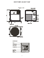
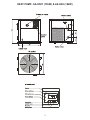
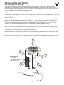
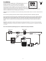
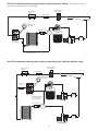
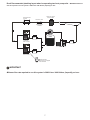
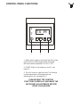
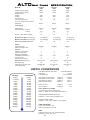
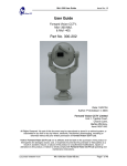
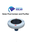
AS-H40Y - 12KW
AS-H50Y - 15KW
AS-H60Y - 18KW
ALTOHeat Pump installation manual
CUSTOMER NAME........................................................................
POOL DEALER..............................................................................
DATE INSTALLED..........................................................................
SERIAL NO.....................................................................................
MODEL...........................................................................................
SAFETY INSTRUCTIONS
Please read this safety instruction carefully before operation.
Heat pump must remain upright at all times.
Do not place objects on to heat pump
Do not disconnect/connect power supply during operation as this may cause serious damage.
Do not insert objects into the air inlet/air outlet grilles.
All electrical connections should be made by a qualified electrician. Do not connect heater to an electrical
supply using a 13 amp plug.
When cleaning the heater unit switch off power supply.
Do not operate electrical switches with wet hands.
Repair or relocation should be carried out by a specialist contractor.
INDEX
Page 4 ...............
Installation and Siting
Page 5 ...............
Plumbing
Page 8 ...............
Electrical Connection & Circuit Diagram
Page 9 ...............
Control Panel Functions F1-F3
Page 11 .............
Control Panel Functions F4-F5
Page 12 .............
Flow Meter
Page 13 .............
Control Panel Error Display E1-E4
Page 14 .............
Auto Restart and Defrosting Function
Page 15 .............
Water Chemistry / Winterising & Start-up Procedure
Page 16 .............
Warranty Policy
Page 17 .............
Heat pump Service & Breakdown
Page 18 .............
Alto Heat Pump Specification
1
HEAT PUMP- AS-H40Y 12kW
2
HEAT PUMP- AS-H50Y (15kW) & AS-H60 (18kW)
3
INSTALLATION AND SITING
Prior to installing your heat pump:All heat pumps are factory assembled and tested prior to delivery. Please check for any external damage
especially to the evaporator fins, please diagram below. Minor damage or indentations to the fins do not affect
performance and can be remedied by your service contractor. If severe damage has occurred please contact your
supplier immediately. Do not attempt to install heater unit.
Siting
As the air flow is discharged from the top of the heat pump all units are designed to be installed outside. If unit is to
be installed inside the filtration/plant room adequate ducting and ventilation must be installed. Please contact your
dealer for advice.
Heater unit must be installed on a solid LEVEL foundation i.e. concrete base or paving slabs. DO NOT PLACE
ONTO SOFT GROUND I.E. GRASS. Please Note: the heat pump collects condensation from the evaporator fins
and will continually discharge small amounts of condensate (water) out of the base of the unit via a drain tube.
Therefore, it is recommended that the drain tube is directed to an area with adequate drainage.
Make sure that heat pump remains free of any obstructions, foliage etc. A minimum clearance is required around
heater unit, please see drawing below. Make sure that easy access can be gained to service panel and plumbing
connections. Do not obstruct access panel with plumbing pipework.
Multiple connections- install heat pumps 500mm apart and independently protect each unit by 20amp MCB - see
also page 7, Drw.4 for plumbing detail.
Min. 3500mm
Make sure that heat pump grilles are not blocked by loose debris such as leaves, grass cuttings, garden furniture.
Mi
n.
10
00
mm
0mm
Mi
. 80
Min
n.
50
Power Supply
Drain Tube
4
0m
m
m
00m
. 10
Min
Evaporator Fins
x 3 sides
(protected by a
wire mesh grille)
PLUMBING
Alto heat pumps are supplied with 1.5" BSP parallel threads, male. We
strongly recommend a 1.5" female socket union is applied to
inlet/outlets for future draining and servicing of the appliance.
2 x1.5” Female/Threaded
Socket Unions Required
Alto heat pumps must be installed in the return line after the filter. If an
existing heater or back-up heater has been installed then the heat pump
should be installed between the filter and the other heater. If solar heating has been installed, the heat pump
should be installed after the solar heating system. See Drw.2
If the heat pump is to be installed at a lower level than the pool then isolation valves or non-return valves should be
installed.
Do not route any plumbing lines across heater inlet panels. All plumbing should be adequately supported.
Once all plumbing connections have been completed the filtration should be turned on and the systems tested for
leaks. A flow meter has been installed next to the control panel. Alto heat pumps will generally take the full flow of
the filtration pump. In some instances if there is too much flow (see page 12 re flow meter) a by-pass may be
required. If there is insufficient flow an auxiliary booster pump may be required. Please contact your dealer for
advice.
Important - (applicable for stainless steel/copper heat exchangers) Standard unit. If your pool has an automatic
chemical dosing appliance the heat pump should be installed prior to the dosing system. See applicable drawings
(1-4) below.
Drw.1 Recommended plumbing layout for a standard heat pump installation.
Position for optional
Erosion Feeder
Back-Up Heater if
required
Non-Return Valve
Pool
Female/ Threaded
Socket Union
FILTER
BACKWASH
FILTER
Condensate
Water to waste
Ball
Valve
PUMP
5
Drw.2 Recommended plumbing layout when incorporating Solar Heating.
If an increased flow rate is
required instal a booster pump as per drw.4 below.
Position for optional
Erosion Feeder
Back-Up Heater if
required
Non-Return Valve
Pool
Female/ Threaded
Socket Union
FILTER
BACKWASH
Non-Return Valve
3-Way
Valve
FILTER
Ball
Valve
Condensate
Water to waste
PUMP
Solar Heating
Install a plumbing bypass for running filtration
& heat pump at night.
Drw.3 Recommended plumbing layout when incorporating Solar Heating & Booster Pump
Position for optional
Erosion Feeder
Back-Up Heater if
required
Non-Return Valve
Pool
Female/ Threaded
Socket Union
FILTER
Non-Return
Valve
BACKWASH
FILTER
Condensate
Water to waste
Ball
Valve
Install a plumbing bypass
for running filtration &
heat pump at night.
PUMP
Non-Return Valve
3-Way
Valve
Ball
Valve
Solar Heating
BOOSTER PUMP
6
Drw.4 Recommended plumbing layout when incorporating two heat pump units.
IMPORTANT Minimum
flow rate required to use this system is 3000 Litres / 660 Gallons (imperial) per hour.
Position for optional
Erosion Feeder
Back-Up Heater if
required
Non-Return Valve
Pool
required or
Errosion Feeder
if installed
FILTER
BACKWASH
FILTER
Ball
Valve
Condensate
Water to waste
Ball
Valve
PUMP
Ball
Valve
Condensate
Water to waste
Female/ Threaded
Socket Union to be applied
on all inlet/outlets
IMPORTANT
Minimum flow rate required to use this system is 3000 Litres / 660 Gallons (imperial) per hour.
7
ELECTRICAL CONNECTION & CIRCUIT DIAGRAM
IMPORTANT. It is recommended that all electrical supplies and connections are carried out by a qualified
electrician, in accordance with I.E.E. standards, latest issue, or local codes of practice as applicable.
Also recommended is a protected supply to incorporate fuses or motor type circuit breakers (Type C) to specified
rating (see Data Sheet page 18).
An earth leakage trip (R.C.D) of the current operating type (30mA) is recommended to be fitted to all pool electric's.
Minimum/Maximum Voltage requirements.:
Single phase machines
50Hz 207v 253v
Three phase machines
50Hz 360v 440v
Cycle Frequency
50Hz 47.5Hz 52.5Hz
N.B. This voltage must be available at the heat pump whilst running.
AS-H40Y (12KW) AS-H50Y (15KW) AS-H60Y (18KW)
SINGLE PHASE (1-N 50HZ)
AS-H40Y (12KW) AS-H50Y (15KW) AS-H60Y (18KW)
SINGLE PHASE WITH SOFT START SYSTEM (1-N 50HZ)
8
CONTROL PANEL FUNCTIONS
1 0 4H0
1
2
3
1. When electric supply is connected the ‘Run’ power
light will be on and the display panel will display
the current water temperature. ie.10 H = 10°C.
2. On/OFF button to turn heater on and off - see
page 10.
3. The ‘set’ button is used to set the F1-5 functions
ie.water temperature, defrosting cycle and
defrosting time etc. see page 10-11
PLEASE READ THE CONTROL
FUNCTIONS CAREFULLY AND MAKE THE
NECESSARY ADJUSTMENTS BEFORE
USING YOUR HEATER
9
CONTROL PANEL FUNCTIONS 1-3
When the ON/OFF buttons is pressed for the first time, the display
panel will display the current water temperature and the desired pool
temperature.
eg. the display may read 10 40 ----- 10 is the current water
temperature 10°C and 40 is the desired water temperature 40°C.
Using the up and down buttons, you can set the swimming pool water
to the desired temperature between +15°C up to + 65°C.
NOTE. WHEN PROCESSING FUNCTIONS F1-F5 IF NO ADJUSTMENTS ARE MADE FOR 5
SECONDS THE DISPLAY WILL REVERT BACK TO THE CURRENT & DESIRED WATER
TEMPERATURE AS ABOVE
When the SET button is used for the first time, the display panel will
display F1-this is to set the temperature differential. The
recommended setting is 2°C. To adjust setting YOU MUST PRESS
THE ON/OFF BUTTON FIRST. Then use the UP and DOWN button to
set the differential temperature range between 0 °C ~ 5°. Press on/off
button again to take you back to the normal display. The unit will now
stop working when the swimming pool water temperature reaches the
setting temperature. The unit will automatically restart when the
swimming pool water temperature drops below the setting temperature.
Eg. If current pool water temperature is 20°C, F1 has been set to 02
(heating mode) when the temperature reaches 20°C the heater will stop
and restart when the water temperature is below 18°C.
When the SET button is pressed twice, the display panel will display
F2- the defrosting cycle. The recommended setting is 30 minutes. To
adjust setting YOU MUST PRESS THE ON/OFF BUTTON FIRST.
Then use the UP and DOWN buttons to adjust defrosting period
between 30 minutes up to 99 minutes. Press on/off button again to take
you back to the normal display. The unit will now start to defrost after
the setting period when the defrosting sensor reaches the frosting
condition.
When the SET button is pressed for the third time, the display panel will
display F3 - the defrosting time. The recommended setting is 5
minutes. To adjust setting YOU MUST PRESS THE ON/OFF BUTTON
FIRST. Use the UP and DOWN buttons to adjust defrosting time
between 3 to 15 minutes. Press on/off button again to take you back to
the normal display.
10
CONTROL PANEL FUNCTIONS 4-5
When the SET button is pressed for the fourth time, the display panel will
display:-
F4 : Operation Mode.
F4 C : Cooling Mode.
F4 H : Heating Mode
When the SET button is pressed for the fifth time, the display panel will
display:-
F5 : The defrosting temperature of the evaporator pipe. The
recommended temperature should be set to -5°C. To adjust setting YOU
MUST PRESS THE ON/OFF BUTTON FIRST. The temperature can be
adjusted using the UP and DOWN buttons between -10°C~ 0°C
Press on/off button again to take you back to the normal display.
11
FLOW METER
area
RED
area
RED
area
After the water heater has been running for more than 15 minutes, it will
be running at full capacity. If you want to make the heat pump run more
efficiently the water flow should be adjusted by checking the pressure
meter display.
If the meter index is in the green area, the water heater is running in the
most efficient way and you do not need to adjust anything.
diagram 1
area
RED
area
A
RED
area
It is not critical if the the pressure reading is not in the green area.
If the reading is marginally in the red area either side do not be
overly concerned, the heater will still function normally.
diagram 2
area
RED
area
In the event that the pressure reading is in the red area ‘A’ (dia.2) it
means there is insufficient water flow. Prior to any adjustments make
sure your filter is clean by using the ‘backwashing and rinse procedure
(refer to your pool hand book for guidance). Check there are no
obstructions in the suction lines i.e. Main Drain or Skimmer(s). If you
are unable to increase the flow rate, please contact your pool dealer as
you may need to increase the size of the filtration pump.
In the event that the pressure reading is in the red area ‘B’ (dia.3) it
means the water flow is too high. You may need to install a bypass to
decrease the water flow until pressure meter enters the green area.
Please contact you dealer for advice.
RED
area
B
diagram 3
12
CONTROL PANEL FUNCTION - ERROR DISPLAY 1-4
IF THE HEATER STOPS WORKING ONE OF THE FOUR ERRORS WILL BE DISPLAYED
THE FAILURE LIGHT WILL BE ON AND THE RELEVANT CODE WILL START TO FLASH
E1: the water temperature sensor is not working correctly.
E2 : the tube sensor is not working correctly.
E3 : Pool filtration is running but water flow is not sensed. Water
flow sensor is not working correctly or there is a lack of water
flow. Backwash filter and check suction lines (Skimmer(s) &
Main Drain(s) for obstruction.
E4 : Indicates high water pressure. High limit pressure switch has
activated and turned off power supply.
13
AUTO RESTART AND DEFROSTING FUNCTION
AUTO RESTART FUNCTION
The Alto water heat pump has an auto restart function. When the power supply is switched off accidentally, it will
automatically save the operation mode.
When the power supply is restored, the unit will automatically restart after five minutes and operate in the same
working mode.
REVERSE CYCLE DEFROST FUNCTION
When the ambient air temperature is too cold, the evaporator will start to freeze and frost will appear on the
evaporator fins. If this happens the heater will automatically enter a defrosting mode (Reverse Cycle Defrost) and
the defrost light will show in the control panel.
This function will make the unit run as it would if it were a normal cooling unit by heating the outdoor coil using hot
gas to melt any frost / ice. Once the evaporator temperature has reached over 23C or the set defrosting time, the
defrost function is over and reverts back to heating the pool water.
FAQ
How long will it take to heat up my pool?
The answer to this is dependant on a number of factors; the ambient air temperature; heater being sized correctly;
solar cover fitted; plumbing configuration etc. As an indication, at the start of the summer season (May) you should
be able to obtain a water temperature of 24°C / 75°F allowing for approximately one week heat up time. This is
providing that filtration is running 24hrs per day and an average ambient air temperature of 16°C / 61°F is
achieved.
When I use a heat pump, should I use a pool cover or solar blanket as well?
Yes. Any reduction in pool heat loss directly translates into savings. 82% of all losses are due to convection. Using
a pool cover just at night will save about 40% of the annual heating cost. A thermal pool cover or solar blanket can
significantly reduce pool heating loss. The use of a solar or thermal blanket will also help extend your pool season.
What is the minimum ambient operating temperature?
The Alto Water Heat Pump will actually operate down to an ambient air temperature of 0°C. but with minimal heat
output. Therefore we recommend that the minimum operating temperature should be 5°C. Other conditions such
as wind, shade and physical location will affect the shut-off temperature of the unit.
Will the heat pump require more refrigerant gas?
Unless the Alto Water Heat Pump has a leak in the sealed refrigeration system, the factory charge of Freon should
last for the life of the unit. Freon is very stable and should not degrade or breakdown even under severe operating
conditions. If your unit needs Freon, then it has a leak, and adding Freon will not solve the problem. The leak must
be located and repaired. Fortunately, Freon leaks are very uncommon and usually are due to transit damage.
How Close To Your Pool?
Normally, the pool pump and Heat Pump are installed close together and within 25 feet of the pool. The longer the
distance from the pool, the more heat loss from the piping. Since normally most of the piping is buried, the heat
loss is minimal for runs of up to 50 feet (50 feet to and from the pump = 100 feet total) unless the ground is wet or
the water table is high. A very rough estimate of heat loss per 100 foot is 2500 BTU/hr for every 10° F difference in
temperature between the pool water and ground surrounding the pipe, which translates to about 3% to 5%
increase in run time.
14
WATER CHEMISTRY
The following water quality must be maintained at all times to prevent premature corrosion. It is
recommended that your water balance is checked and balanced by a pool professional. Your warranty
does not cover for damaged caused by poor water chemistry and neglect.
pH:
Total Alkalinity:
Total hardness:
Total Dissolved solids:
Saline Water max:
Chlorine Free Cl:
Cyanuric level
Super chlorination Max:
Bromine:
Baquacil:
7.2 -7.6
80 - 120ppm
Less thab 500ppm
1500ppm or lower
concentration 6%
5ppm Max. Continuous
50ppm Max.
30ppm for 24hrs
8ppm
25-50ppm
Surface skimmers (above or inground)
Do not use slow dissolving chemical tablets such as chlorine in the skimmer basket(s). This can lead to high
acidic/corrosive pool water affecting the heat exchanger and resulting in a replacement of the whole unit.
Therefore, we recommend that diluted chemicals are fed directly to the pool water or use an automatic dosing
device.
WINTERISING / START-UP procedure - ALL MODELS
Winterising Procedure
1. Switch off electric supply to heat pump.
2. Turn off circulation pump.
3. Drain water from heat pump by disconnecting pipework to and from heat pump.
Ensure Heat Pump is completely drained.
4. Flush through water circuit in heat pump using clean tap water i.e. a hose into inlet connection - run
for 10 minutes minimum
5. Drain completely - fit plastic bags secured by elastic bands over water connections.
6. If desired, you can protect from the heater by covering with VENTILATED cover through the winter
season. Do not use plastic sheet as condensation can occur within unit.
NOTE. If the pool has a ‘frost-thermostat’ installed to prevent the pool system from being drained in the
winter months, it is recommended that a plumbing by-pass is installed to prevent unnecessary water flow
through the heater unit.
Start-Up Procedure
1. Remove ventilated cover protection is fitted.
2. Re-connect all plumbing connections to heat pump, filtration etc.
3. Turn on circulation pump and check for leaks.
4. Use control panel to set functions 1-7.
5. Check daily to ensure pool water has the correct pH and the correct chemical balance is being
maintained.
15
ALTO WARRANTY POLICY
This voluntary policy is supplemental to and in no way affects any statutory rights which the
customer may have.
1
Warranties
1.1
Paramount Pools warrants the Alto Heat Pump for a period of one (1) year from the date installed for both
parts and labour.
1.2
At the end of the first year the following warranties apply as to parts only; labour is excluded from these
warranties:-
1.2.1
The condenser and compressor are warranted for three (3) years;
1.2.2
The stainless steel copper heat exchanger is warranted for three (3) years;
12.3
The titanium heat exchanger is warranted for five (5) years.
2
Exclusions - This warranty does not include the following:-
2.1
The repair of damage due to negligence; abuse or improper installation;
2.1
Incorrect winter de-commissioning;
2.3
Improper operation;
2.4
Improper use of pool chemicals;
2.5
Operation environment;
2.6
Failure to provide reasonable and necessary maintenance;
2.7
Accident or other conditions beyond the normal intended use of the unit;
2.8
Any misuse of the equipment;
2.9
The occurrence of superficial corrosion to the external housing cabinet of the heat pump;
2.10
The furnishings of refrigerant and other expendable material.
3
Conditions for Warranty
The warranty only applies on the following conditions:The customer is to pay for all charges for the Alto Heat Pump in accordance with the original terms of sale.
3.1
3.2
All repairs, replacements must be carried out by an authorised service agent appointed by Paramount
Pools.
3.3
This warranty extends only to the original consumer who purchased the Alto Heat Pump.
3.4
The warranty terminates upon the transfer of ownership or if the heat pump is relocated save with the
written permission of Paramount Pools.
3.5
The warranty is only applicable to installations in England, Scotland and Wales.
4
Damages
4.1
Paramount Pools is not liable for any damages of any sort whatsoever, including incidental and
consequential damages.
4.2
Parts returned under the terms of this warranty will be repaired or replaced and return transportation
charges pre-paid within the UK by the best and most economical means
4.3
To the extent permitted by law liability under or in connection with this warranty whether arising in contract
or negligence; breach of statutory duty or otherwise, shall not exceed the value of the contract.
5
5.1
Miscellaneous
This warranty shall be governed by and construed in accordance with the laws of England and Wales and
each party agrees to submit to the jurisdiction of the Courts within England and Wales.
This warranty is in lieu of all other warranties expressed or implied, written or oral save as prescribed by
statute.
5.2
5.3
5.4
There are no implied warranties of fitness for a particular purpose that apply to this product.
Any provisions of this contract which is or may be void or unenforceable shall to the extent of such invalidity
or unenforceability be deemed severable and shall not affect any other provision of this contract.
16
HEAT PUMP SERVICE
An Alto heat pump should give you many years trouble free service. However, to obtain the
maximum efficiency from your heater Alto recommend that your heater is checked and
serviced every 12 months. Service & extended warranty packages are available from a UK Service Agent
(see contact detail below).
HEAT PUMP BREAKDOWN
If you think there is a problem with your heater and are not able to diagnose the fault please contact your
POOL DEALER initially to discuss the symptoms.
BEFORE YOU CALL
To help you prevent unnecessary service call outs, please check the following points:·
·
·
·
·
·
·
·
·
·
·
·
·
·
Is there an electric supply to the heater?
Is there a power cut?
Have you checked all the house fuses, R.C.D trip?
Has the electrical supply been disconnected?
If installed is the time clock correct?
Have checked you the flow metre?
Is there enough water flow?
Has the filtration been running for a minimum of twelve hours per day?
Is there any obstruction in the skimmer?
Is there any obstruction in the pump basket?
Is the water at the correct operational level?
Is the filter pump working?
Is the filter operating pressure correct?
Does the filter require backwashing?
Have you checked the diagnostic control panel?
If the fault can not be diagnosed over the phone then your pool dealer will contact Paramount Pool
Products (UK Importer) who will arrange an appointed UK SERVICE AGENT (Regal Environmental
Systems Ltd) to contact you with a suitable date and time to service the heater unit.
Please have the following information available:1.
Serial number (located on the aluminum plate placed externally on the heat pump casing) and
the approximate date the unit was installed. (this information should be on the front cover of this
manual)
2.
Proof of Installation Date (Bill of sale or original invoice only)
3.
Description of the Symptoms.
UK IMPORTER: Paramount Pool Products London Road Hartley Wintney Hook Hants RG27 8HY TEL.
01252 842891 FAX 01252 842388
UK SERVICE AGENT: Regal Environmental Systems Ltd Regal House Upham Street, Upham,
Southampton SO32 1JA TEL01489 860966 FAX 01489 860977
17
ALTOHeat Pumps - SPECIFICATION
Model No.
AS-H40Y
12kW
AS-H50Y
15kW
AS-H60Y
18kW
Heating Capacity (Btu/h)
Cooling Capacity (Btu/h)
Rated Input (w)
Heating
Cooling
PTC Power (w)
COP for Heating (w/w)
(at 20 °C ambient air temperature)
40000
35000
50000
42000
60000
55000
2540
2465
-------4.42
3185
3020
-------4.40
3790
3900
-------4.44
Refrigerant
R407C
R407C
R407C
230/1/50
11.3
10.9
-------32
230/1/50
14.1
13.4
-------36
230/1/50
16.8
17.3
-----40
Power Supply
Volt/Phase/Hz
Rated Current (A) -Heating
Cooling
LRA (A) - (Max. Start-up AMPS)
Minimum Flow Rate m3/h (imp.gls)
2.5 (550 gls)
2.5 (550 gls)
2.5 (550 gls)
Maximum Flow Rate m3/h (imp.gls)
10.0 (2200 gls)
13.0 (2850 gls)
18.0 (3975 gls)
Noise Level (whole unit) at 3m
<52
<54
<58
ROTARY
Y
ROTARY
Y
SCROLL
Y
Features
Electronic Control Panel
Soft Touch Key Pads
Backlight LCD Display
Temperature Indicator(°C)
24 Hours Timer
Drain Hose connection
Y
Y
Y
5~45
Y
Y
Y
Y
Y
5~45
Y
Y
Y
Y
Y
5~45
Y
Y
Dimensions WxHxD (mm)
Net Weight (Kg)
480×755×515
65
580×715×610
74
580×715×610
98
Packing Dim. WxHxD (mm)
Gross Weight (Kg)
540×835×540
70
630×770×710
84
630×770×710
110
System
Compressor type
Electric expansion valve
USEFUL CONVERSIONS
CELSIUS
-40 deg.
-17.8 deg.
- 10 deg.
0 deg.
5 deg.
10 deg.
15 deg.
20 deg.
25 deg.
30 deg.
35 deg.
40 deg.
50 deg.
60 deg.
70 deg.
80 deg.
90 deg.
100 deg.
FAHRENHEIT
-40
0
14
32
41
50
59
68
77
86
95
104
122
140
158
176
194
212
deg.
deg.
deg.
deg.
deg.
deg.
deg.
deg.
deg.
deg.
deg.
deg.
deg.
deg.
deg.
deg.
deg.
deg.
1,000 British Thermal Units (BTU)
10,000 BTU
1 UK Horsepower
= 0.293 kilowatt/hour
= 1 therm
= 0.7457 kilowatt
Cubic Yards to Cubic Metres
Cubic Metres to Cubic Yards
Cubic Metres to Gallons
Gallons to Cubic Metres
multiply by
multiply by
multiply by
divide by
0.764555
1.30795
220.717
220.717
Gallons to Litres
Litres to Gallons
multiply by
multiply by
4.546
0.22
POOL CAPACITY / VOLUME
To calculate pool capacity measure the
Length ‘L’ - Width ‘W’ - and average water depth ‘D’.
SQUARE OR RECTANGULAR POOLS
CAPACITY = L X W X D X 6.25 gallons (U.K)
ROUND OR OVAL POOLS
CAPACITY = DIA. X DIA. X DEPTH X 4.90 gallons
PUMP CONVERSION
Horse power to Watts x 746
Watts to Horse Power x 0.00134
AREA
Surface area of a Circle 3.14 x Radius(squared)
Perimeter of a circle 3.14 x Dia.
18