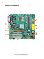
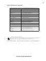
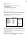
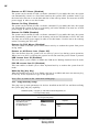
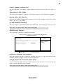
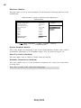
1
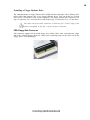
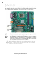
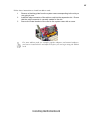
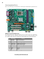
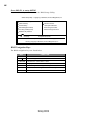
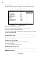
Manual
Motherboard P4M800Pro-M
Preface
Copyright
This publication, including all photographs, illustrations and software, is protected under
international copyright laws, with all rights reserved. Neither this manual, nor any of the
material contained herein, may be reproduced without written consent of the author.
Version 1.0a
Disclaimer
The information in this document is subject to change without notice. The manufacturer
makes no representations or warranties with respect to the contents hereof and specifically
disclaims any implied warranties of merchantability or fitness for any particular purpose.
The manufacturer reserves the right to revise this publication and to make changes from
time to time in the content hereof without obligation of the manufacturer to notify any
person of such revision or changes.
Trademark Recognition
Microsoft, MS-DOS and Windows are registered trademarks of Microsoft Corp.
MMX, Pentium, Pentium-II, Pentium-III, Pentium-4, Celeron are registered trademarks of
Intel Corporation.
Other product names used in this manual are the properties of their respective owners and
are acknowledged.
Federal Communications Commission (FCC)
This equipment has been tested and found to comply with the limits for a Class B digital
device, pursuant to Part 15 of the FCC Rules. These limits are designed to provide reasonable protection against harmful interference in a residential installation. This equipment
generates, uses, and can radiate radio frequency energy and, if not installed and used in
accordance with the instructions, may cause harmful interference to radio communications.
However, there is no guarantee that interference will not occur in a particular installation.
If this equipment does cause harmful interference to radio or television reception, which
can be determined by turning the equipment off and on, the user is encouraged to try to
correct the interference by one or more of the following measures:
•
•
•
•
Reorient or relocate the receiving antenna
Increase the separation between the equipment and the receiver
Connect the equipment onto an outlet on a circuit different from that to which
the receiver is connected
Consult the dealer or an experienced radio/TV technician for help
Shielded interconnect cables and a shielded AC power cable must be employed with this
equipment to ensure compliance with the pertinent RF emission limits governing this
device. Changes or modifications not expressly approved by the system’s manufacturer
could void the user’s authority to operate the equipment.
Preface
ii
Declaration of Conformity
This device complies with part 15 of the FCC rules. Operation is subject to the following
conditions:
•
•
This device may not cause harmful interference, and
This device must accept any interference received, including interference
that may cause undesired operation
Canadian Department of Communications
This class B digital apparatus meets all requirements of the Canadian Interference-causing
Equipment Regulations.
Cet appareil numérique de la classe B respecte toutes les exigences du Réglement sur le
matériel brouilieur du Canada.
About the Manual
The manual consists of the following:
Chapter 1
Introducing the Motherboard
Describes features of the motherboard.
Go to
Chapter 2
Installing the Motherboard
Using BIOS
page 1
Describes installation of motherboard
components.
Go to
Chapter 3
H
H
page 7
Provides information on using the BIOS
Setup Utility.
Go to
Preface
H
page 27
iii
TABLE OF CONTENTS
Preface
i
Chapter 1
1
Introducing the Motherboard
1
Introduction.................................................................................................1
Feature..........................................................................................................2
Motherboard Components........................................................................4
Chapter 2
7
Installing the Motherboard
7
Safety Precautions......................................................................................7
Choosing a Computer Case.......................................................................7
Installing the Motherboard in a Case......................................................7
Checking Jumper Settings.........................................................................8
Setting Jumpers..............................................................................8
Checking Jumper Settings..............................................................9
Jumper Settings..............................................................................9
Connecting Case Components...............................................................10
Front Panel Connector.................................................................12
Installing Hardware...................................................................................13
Installing the Processor...............................................................13
Installing Memory Modules.........................................................15
Installing a Hard Disk Drive/CD-ROM/SATA Hard Drive........18
Installing a Floppy Diskette Drive...............................................20
Installing Add-on Cards..............................................................21
Connecting Optional Devices......................................................23
Connecting I/O Devices..........................................................................26
Chapter 3
27
Using BIOS
27
About the Setup Utility............................................................................27
The Standard Configuration........................................................27
Entering the Setup Utility..............................................................27
Updating the BIOS.......................................................................29
Using BIOS................................................................................................29
Standard CMOS Setup.................................................................30
Advanced Setup............................................................................30
Features Setup.............................................................................32
iv
Power Management Setup...........................................................33
PCI/Plug and Play Setup.............................................................34
BIOS Security Features................................................................35
Hardware Monitor.......................................................................36
Load Optimal Defaults................................................................37
Save Changes and Exit................................................................37
Discard Changes and Exit...........................................................37
1
Chapter 1
Introducing the Motherboard
Introduction
Thank you for choosing the P4M800PRO-M motherboard. This motherboard is a high
performance, enhanced function motherboard that supports LGA775 Pentium 4/Celeron
D/Pentium D processors for high-end business or personal desktop markets.
The motherboard incorporates the P4M800PRO Northbridge (NB) and VT8237 Southbridge
(SB) chipsets. The Northbridge supports a Front Side Bus (FSB) frequency of 1066/ 800/533
MHz FSB and Hyper-Threading technology. The memory controller supports DDR memory
DIMM frequencies of 400/333/266 MHz or DDR2 memory DIMM frequencies of 533/400
MHz. It supports four DDR Sockets with up to maximum memory of 2 GB. Aside from the
integrated UniChrome Pro 3D/2D Graphics & Video Controller, one AGP 8X/4X slot
provides users with high-performance along with superior image and video quality.
The VT8237 Southbridge is a highly integrated peripheral controller, it includes an integrated keyboard controller with PS2 mouse support, two-channel Serial ATA/RAID hard
disk controller, master mode enhanced Parallel IDE controller with full scatter/gather
capability and extension to UltraDMA-133/100/66 for 133/100/66 MB/sec transfer rate,
integrated USB 2.0 interface, supporting up to eight functional ports, and OnNow/ACPI
compliant advanced configuration and power management interface. The VT8237 integrated networking MAC controller with standard MII interface to an external PHY for 100/
10/1Mb Base-T Ethernet.
This motherboard is equipped with advanced full set of I/O ports in the rear panel, including
PS/2 mouse and keyboard connectors, COM1, LPT1, one VGA port, four USB ports, one
optional LAN port, and audio jacks for microphone, line-in and line out.
Introducing the Motherboard
2
Feature
Processor
This motherboard uses an LGA775 type of Pentium 4 that carries the following features:
•
•
•
Accommodates Intel Pentium 4/Celeron D/Pentium D processors
Supports a system bus (FSB) of 1066/ 800/533 MHz
Supports “Hyper-Threading” technology CPU
“Hyper-Threading” technology enables the operating system into thinking it’s hooked
up to two processors, allowing two threads to be run in parallel, both on separate
“logical” processors within the same physical processor.
Chipset
The P4M800PRO Northbridge (NB) and VT8237 Southbridge (SB) chipset is based on
an innovative and scalable architecture with proven reliability and performance.
P4M800PRO
(NB)
•
•
•
•
•
High performance Northbridge with 1066 /800/533 MHz FSB
for Pentium 4/Celeron D/Pentium D processors
V-Link 533 MB/s high bandwidth North/South Bridge interconnect
Integrated UniChrome Pro 3D/2D Graphics & Video Controller, Microsoft DirectX 9.0 compatible, OpenGL supported
Supports for AGP 8X/4X, AGP v3.0 compliant with 1.5V
Advanced 64-bit DDR2 and DDR400 SDRAM controller
P4M800PRO chipset can only support mixed 1024/512/256/
128/64Mb x8/16 DDR2 SDRAMs or mixed 1024/512/256/128/
64Mb x8/16 DDR SDRAMs.
VT8237(SB)
•
•
•
•
•
•
Supports 16-bit 66 MHz V-Link Host interface with total
bandwidth of 1066 MB/s
Compliant with PCI 2.2 specification at 33 MHz, supporting
up to 6 PCI masters
Integrated Serial ATA Host Controllers, supporting data transfer rates up to 1.5Gb/s
Integrated Dual channel UltraDMA 133/100/66 Master Mode
EIDE Controller
USB 2.0 Controller, supporting up to 8 USB 2.0 ports
Integrated keyboard Controller with PS2 mouse support
Memory
•
•
•
Supports DDR 400/333/266 MHz or DDR2 533/400 DDR SDRAM DIMMs
Accommodates four unbuffered DIMMs
Up to 1 GB per DIMM with maximum memory size up to 2 GB
Users please note that DDR & DDR2 can’t both be applied at the same time on
this motherboard. Users can use either DDR or DDR2 memory modules only!
Introducing the Motherboard
3
Audio
•
•
•
•
Compliant with AC’97 2.3 specification
16-bit Stereo full-duplex CODEC with 48KHz sampling rate
Supports double sampling rate (96KHz) of DVD audio playback
Direct Sound 3DTM compatible
Onboard LAN (Optional)
The onboard LAN controller provides either of the following features:
•
•
•
Supports 10 Mb/s and 100 Mb/s N-way Auto-negotiation operation
Supports Wake-on-LAN function and remote wake-up
Half/Full Duplex capability
•
•
•
•
Integrated 10/100/1000 transceiver
Supports PCI rev.2.3,32-bit,33/66 MHz
Crossover Detection & Auto-Correction
Wake-on-LAN and remote wake-up support
Expansion Options
The motherboard comes with the following expansion options:
•
•
•
•
•
One AGP slot
Three 32-bit PCI v2.2 compliant slots
Two 40-pin IDE connectors supporting up to 4 IDE devices
One floppy disk drive interface
Two 7-pin SATA connectors
This motherboard supports UltraDMA bus mastering with transfer rates of 133/100/66
MB/s.
Integrated I/O
The motherboard has a full set of I/O ports and connectors:
•
•
•
•
•
•
•
Two PS/2 ports for mouse and keyboard
One serial port
One parallel port
One VGA port
Four USB ports
One LAN port (optional)
Audio jacks for microphone, line-in and line-out
BIOS Firmware
This motherboard uses AMI BIOS that enables users to configure system features
including the following:
•
Power management
•
Wake-up alarms
•
CPU parameters
•
CPU and memroy timing
The firmware can also be used to set parameters for different processor clock speeds.
Some hardware specifications and software items are subject to change
without prior notice.
Introducing the Motherboard
4
Floppydiskettedriveconnector
Motherboard Components
1
2
3
4
18
17
5
6
16
7
8
9
15
14
13
12
11
Introducing the Motherboard
10
5
Table of Motherboard Components
LABEL
1 CPU Socket
2 CPU_FAN
3 DDRII1~2
4 ATX1
6 IDE1
6 IDE2
7 CLR_CMOS
8 BIOS_WP *
COMPONENT
LGA775 socket for P4/Celeron D CPUs
CPU cooling fan connector
240-pin DDR2 SDRAM slots
Standard 24-pin ATX power connector
Primary IDE channel
Secondary IDE channel
Clear CMOS jumper
BIOS protect jumper
9 SATA1~2
10 PANEL1
11 USB 3/4
12 FDD
13 AUX IN
14 AUX_OUT
Serial ATA connectors
Front Panel switch/LED header
Front Panel USB headers
Floppydiskettedriveconnector
audio input
Auxiliary audio output header
15 PCI1~3
16 AGP
17 SYS_FAN
18 ATX12V
32-bit add-on card slots
Accelerated Graphics Port slot
System cooling fan connector
Auxiliary 4-pin power connector
* Stands for optional components
Users please note that DDR & DDR2 can’t both be applied at the same time on
this motherboard. Users can use DDR2 memory modules only!
This concludes Chapter 1. The next chapter explains how to install the motherboard.
Introducing the Motherboard
6
Memo
Introducing the Motherboard
7
Chapter 2
Installing the Motherboard
Safety Precautions
•
•
•
•
•
Follow these safety precautions when installing the motherboard
Wear a grounding strap attached to a grounded device to avoid damage from
static electricity
Discharge static electricity by touching the metal case of a safely grounded
object before working on the motherboard
Leave components in the static-proof bags they came in
Hold all circuit boards by the edges. Do not bend circuit boards
Choosing a Computer Case
There are many types of computer cases on the market. The motherboard complies with
the specifications for the Micro ATX system case. First, some features on the motherboard
are implemented by cabling connectors on the motherboard to indicators and switches on
the system case. Make sure that your case supports all the features required. Secondly, this
motherboard supports one or two floppy diskette drives and four enhanced IDE drives.
Make sure that your case has sufficient power and space for all drives that you intend to
install.
Most cases have a choice of I/O templates in the rear panel. Make sure that the I/O
template in the case matches the I/O ports installed on the rear edge of the motherboard.
This motherboard carries a Micro ATX form factor of 244 x 244 mm. Choose a case that
accommodates this form factor.
Installing the Motherboard in a Case
Refer to the following illustration and instructions for installing the motherboard in a case.
Most system cases have mounting brackets installed in the case, which correspond the holes
in the motherboard. Place the motherboard over the mounting brackets and secure the
motherboard onto the mounting brackets with screws.
Ensure that your case has an I/O template that supports the I/O ports and expansion slots
on your motherboard.
Installing the Motherboard
8
Do not over-tighten the screws as this can stress the motherboard.
Checking Jumper Settings
This section explains how to set jumpers for correct configuration of the motherboard.
Setting Jumpers
Use the motherboard jumpers to set system configuration options. Jumpers with more than
one pin are numbered. When setting the jumpers, ensure that the jumper caps are placed on
the correct pins.
The illustrations show a 2-pin jumper. When
the jumper cap is placed on both pins, the
jumper is SHORT. If you remove the jumper
cap, or place the jumper cap on just one pin,
the jumper is OPEN.
SHORT
This illustration shows a 3-pin jumper. Pins
1 and 2 are SHORT
Installing the Motherboard
OPEN
9
Checking Jumper Settings
The following illustration shows the location of the motherboard jumpers. Pin 1 is labeled.
Jumper Settings
Jumper
Type
Description
Setting (default)
1-2: NORMAL
CLR_CMOS
BIOS_WP
3-pin
2-pin
Clear CMOS
2-3: CMOS CLEAR
Before clearing the
CMOS, make sure to
turn off the system.
1
CLR_CMOS
OPEN: FLASH WRITE
UNPROTECTED
BIOS_WP
SHORT: FLASH WRITE
PROTECTED
BIOS_WP
To avoid the system unstability after clearing CMOS, we recommend
users to enter the main BIOS setting page to “Load Optimal Defaults” and then “Save Changes and Exit”.
Installing the Motherboard
10
Connecting Case Components
After you have installed the motherboard into a case, you can begin connecting the motherboard components. Refer to the following:
1
2
3
4
5
Connect the CPU cooling fan cable to CPU_FAN.
Connect the system cooling fan connector to SYS_FAN.
Connect the case switches and indicator LEDs to the PANEL1.
Connect the standard power supply connector to ATX1.
Connect the auxiliary case power supply connector to ATX_12V.
Connecting 20/24-pin power cable
Users please note that the 20-pin and 24-pin power cables can both be connected to the ATX1 connector. With the 20-pin power cable, just align the 20pin power cable with the pin 1 of the ATX1 connector. However, using 20-pin
power cable may cause the system to become unbootable or unstable because of
insufficient electricity. A minimum power of 300W is recommended for a fullyconfigured system.
20-pin power cable
With ATX v1.x power supply, users please
note that when installing 20-pin power cable,
the latche of power cable clings to the left
side of the ATX_POWER connector latch,
just as the picture shows.
With ATX v2.x power supply, users please
note that when installing 24-pin power cable,
the latches of power cable clings to the right
side of the ATX_POWER connector latch.
24-pin power cable
Installing the Motherboard
11
CPU_FAN: CPU FAN Power Connector
Pin
Signal Name
Function
1
2
3
GND
Sense
System Ground
Power +12V
Sensor
4
PWM
CPU FAN control
+12V
Users please note that the fan connector supports the CPU cooling
fan of 1.1A~2.2A (26.4W max.) at +12V.
SYS_FAN: System cooling FAN Power Connector
Pin
1
2
3
Signal Name
Function
System Ground
Power +12V
Sensor
GND
+12V
Sense
ATX_12V: ATX 12V Power Connector
Pin
1
2
3
4
Signal Name
Ground
Ground
+12V
+12V
ATX1: ATX 24-pin Power Connector
Pin
Signal Name
Pin
Signal Name
1
2
+3.3V
+3.3V
+3.3V
13
14
3
Ground
15
Ground
4
+5V
16
PS_ON
5
6
7
8
9
Ground
+5V
Ground
17
18
19
20
21
Ground
Ground
Ground
10
11
12
+12V
22
23
24
+5V
PWRGD
+5VSB
+12V
+3.3V
-12V
-5V
+5V
+5V
Ground
Installing the Motherboard
12
Front Panel Connector
The front panel connector (PANEL1) provides a standard set of switch and LED connectors commonly found on ATX or micro-ATX cases. Refer to the table below for information:
PANEL1
Pin
Signal
Function
1
Pin
Signal
Function
HD_LED_P Hard disk LED(+) 2 FP PWR/SLP *MSG LED(+)
3
HD_LED_N Hard disk LED(-)
4
FP PWR/SLP *MSG LED(-)
5
RST_SW_N Reset Switch(-)
6
PWR_SW_P Power Switch(+)
7
RST_SW_P
Reset Switch(+)
8
PWR_SW_N Power Switch(-)
9
RSVD
Reserved
10 Key
No pin
* MSG LED (dual color or single color)
Hard Drive Activity LED
Connecting pins 1 and 3 to a front panel mounted LED provides visual indication that data
is being read from or written to the hard drive. For the LED to function properly, an IDE
drive should be connected to the onboard IDE interface. The LED will also show activity
for devices connected to the SCSI (hard drive activity LED) connector.
Power/Sleep/Message waiting LED
Connecting pins 2 and 4 to a single or dual-color, front panel mounted LED provides power
on/off, sleep, and message waiting indication.
Reset Switch
Supporting the reset function requires connecting pin 5 and 7 to a momentary-contact
switch that is normally open. When the switch is closed, the board resets and runs POST.
Power Switch
Supporting the power on/off function requires connecting pins 6 and 8 to a momentarycontact switch that is normally open. The switch should maintain contact for at least 50 ms
to signal the power supply to switch on or off. The time requirement is due to internal debounce circuitry. After receiving a power on/off signal, at least two seconds elapses before
the power supply recognizes another on/off signal.
Installing the Motherboard
13
Installing Hardware
Installing the Processor
Caution: When installing a CPU heatsink and cooling fan make sure that
you DO NOT scratch the motherboard or any of the surface-mount
resistors with the clip of the cooling fan. If the clip of the cooling fan
scrapes across the motherboard, you may cause serious damage to the
motherboard or its components.
On most motherboards, there are small surface-mount resistors near the
processor socket, which may be damaged if the cooling fan is carelessly
installed.
Avoid using cooling fans with sharp edges on the fan casing and the clips.
Also, install the cooling fan in a well-lit work area so that you can clearly
see the motherboard and processor socket.
Before installing the Processor
This motherboard automatically determines the CPU clock frequency and system bus
frequency for the processor. You may be able to change these settings by making changes
to jumpers on the motherboard, or changing the settings in the system Setup Utility. We
strongly recommend that you do not over-clock processors or other components to run
faster than their rated speed.
Warning: Over-clocking components can adversely affect the reliability
of the system and introduce errors into your system. Over-clocking can
permanently damage the motherboard by generating excess heat in
components that are run beyond the rated limits.
This motherboard has a LGA 775 socket. When choosing a processor, consider the performance requirements of the system. Performance is based on the processor design, the clock
speed and system bus frequency of the processor, and the quantity of internal cache memory
and external cache memory.
Installing the Motherboard
14
CPU Installation Procedure
The following illustration shows CPU installation components.
A. Unload the cap
· Use thumb & forefinger to hold the
lifting tab of the cap.
· Lift the cap up and remove the cap
completely from the socket.
B. Open the load plate
· Use thumb & forefinger to hold the
hook of the lever, pushing down and pulling
aside unlock it.
· Lift up the lever.
· Use thumb to open the load plate. Be
careful not to touch the contacts.
C. Install the CPU on the socket
· Orientate CPU package to the socket.
Make sure you match triangle marker
to pin 1 location.
D. Close the load plate
· Slightly push down the load plate onto the
tongue side, and hook the lever.
· CPU is locked completely.
E. Apply thermal grease on top of the CPU.
F.
Fasten the cooling fan supporting base onto
the CPU socket on the motherboard.
G. Make sure the CPU fan is plugged to the
CPU fan connector. Please refer to the CPU
cooling fan user’s manual for more detail
installation procedure.
1. To achieve better airflow rates and heat dissipation, we suggest that you
use a high quality fan with 3800 rpm at least. CPU fan and heatsink
installation procedures may vary with the type of CPU fan/heatsink supplied. The form and size of fan/heatsink may also vary.
2. DO NOT remove the CPU cap from the socket before installing a CPU.
Installing the Motherboard
15
Installing Memory Modules
This motherboard accomodates four memory modules. It can support two 184-pin unbuffered DIMM, DDR 400/333/266 or two 240-pin DDR2 533/400. The total memory
support capacity is 2 GB.
Users please note that DDR & DDR2 can’t both be applied at the same time on
this motherboard. Users can use either DDR or DDR2 memory modules only!
DDR SDRAM memory module table
Memory module
Memory Bus
DDR 266
DDR 333
DDR 400
133MHz
166MHz
200MHz
DDR2 SDRAM memory module table
Memory module
Memory Bus
DDR2 400
DDR2 533
200MHz
266MHz
You must install at least one module in any of the four slots. Each module can be installed
with 256 MB to 1 GB of memory; total support memory capacity is 2 GB.
Do not remove any memory module from its antistatic packaging until you
are ready to install it on the motherboard. Handle the modules only by
their edges. Do not touch the components or metal parts. Always wear a
grounding strap when you handle the modules.
Installation Procedure
Refer to the following to install the memory modules.
1
2
3
4
5
6
This motherboard supports unbuffered DDR and DDR2 SDRAM .
Push the latches on each side of the DIMM slot down.
Align the memory module with the slot. The DIMM slots are keyed with
notches and the DIMMs are keyed with cutouts so that they can only be
installed correctly.
Check that the cutouts on the DIMM module edge connector match the notches
in the DIMM slot.
Install the DIMM module into the slot and press it firmly down until it seats
correctly. The slot latches are levered upwards and latch on to the edges of
the DIMM.
Install any remaining DIMM modules.
Installing the Motherboard
16
Table B: Supported DDR2 QVL (Qualified Vendor List)
Type
Size
256 MB
DDR2 400
512 MB
Vendor
Module Name
Hynix
HYMP532U646-E3 AA
Nanya
NT256T64UH4A0F-5A CL3
Samsung
M378T3253FG0-CCC
Hynix
HYMP564U648-E3 AA
Corsair
4PB11D9CHM
Eipida
B04180WB00
Corsair
4PB11D9CHM
Eipida
04180WB01
Kingston
HY5PS56821
Twinmos Elpida
8D22JB-ED
Twinmos Hynix
8D22JB-HX
Samsung
K4T56083QF-ZCD5
Apacer ELPIDA
E5108AB-5C-E
Kingston Infineon
HYB18T51260AF-E
256 MB
512 MB
DDR2 533
1 GB
Installing the Motherboard
17
Installing a Hard Dish Drive/CD-ROM/SATA Hard Drive
This section describes how to install IDE devices such as a hard disk drive and a CD-ROM
drive.
About IDE Devices
Your motherboard has two IDE channels interface. An IDE ribbon cable supporting two IDE
devices is bundled with the motherboard.
You must orient the cable connector so that the pin1 (color) edge of the
cable correspoinds to the pin 1 of the I/O port connector.
IDE1: IDE Connector
This motherboard supports two high data transfer SATA ports with each runs up to 150
MB/s. To get better system performance, we recommend users connect the CD-ROM to
the IDE channel, and set up the hard dives on the SATA ports.
IDE2: Secondary IDE Connector
The second drive on this controller must be set to slave mode. The cinfiguration is the same
as IDE1.
IDE devices enclose jumpers or switches used to set the IDE device as MASTER or SLAVE.
Refer to the IDE device user’s manual. Installing two IDE devices on one cable, ensure that
one device is set to MASTER and the other device is set to SLAVE. The documentation of
your IDE device explains how to do this.
Installing the Motherboard
18
About SATA Connectors
Your motherboard features two SATA connectors supporting a total of two drives. SATA , or
Serial ATA (Advanced Technology Attachment) is the standard interface for the IDE hard
drives which are currently used in most PCs. These connectors are well designed and will
only fit in one orientation. Locate the SATA connectors on the motherboard and follow the
illustration below to install the SATA hard drives.
Installing Serial ATA Hard Drives
To install the Serial ATA (SATA) hard drives, use the SATA cable that supports the Serial
ATA protocol. This SATA cable comes with an SATA power cable. You can connect either
end of the SATA cable to the SATA hard drive or the connector on the motherboard (not
contained in the scope of supply).
SATA cable
Refer to
1
2
3
(optional)
SATA power cable
(optional)
the illustration below for proper installation:
Attach either cable end to the connector on the motherboard.
Attach the other cable end to the SATA hard drive.
Attach the SATA power cable to the SATA hard drive and connect the other
end to the power supply.
This motherboard does not support the “Hot-Plug” function.
Installing the Motherboard
19
Installing a Floppy Diskette Drive
The motherboard has a floppy diskette drive (FDD) interface and ships with a diskette drive
ribbon cable that supports one or two floppy diskette drives. You can install a 5.25-inch
drive and a 3.5-inch drive with various capacities. The floppy diskette drive cable has one
type of connector for a 5.25-inch drive and another type of connector for a 3.5-inch drive.
You must orient the cable connector so that the pin 1 (color) edge of the
cable corresponds to the pin 1 of the I/O port connector.
FDD: Floppy Disk Connector
This connector supports the provided floppy drive ribbon cable. After connecting the single
end to the onboard floppy connector, connect the remaining plugs on the other end to the
floppy drives correspondingly.
Installing the Motherboard
20
Installing Add-on Cards
The slots on this motherboard are designed to hold expansion cards and connect them to the
system bus. Expansion slots are a means of adding or enhancing the motherboard’s features
and capabilities. With these efficient facilities, you can increase the motherboard’s capabilities by adding hardware that performs tasks that are not part of the basic system.
AGP
Slot
The AGP slot is used to install a graphics adapter that supports the 8X/4X
AGP specification. It is AGP 3.0 compliant.
PCI 1~3
Slots
This motherboard is equipped with three standard PCI slots. PCI stands for
Peripheral Component Interconnect and is a bus standard for expansion
cards, which for the most part, is a supplement of the older ISA bus standard.
The PCI slots on this board are PCI v2.2 compliant.
Before installing an add-on card, check the documentation for the card
carefully. If the card is not Plug and Play, you may have to manually
configure the card before installation.
Installing the Motherboard
21
Follow these instructions to install an add-on card:
1
2
3
Remove a blanking plate from the system case corresponding to the slot you
are going to use.
Install the edge connector of the add-on card into the expansion slot. Ensure
that the edge connector is correctly seated in the slot.
Secure the metal bracket of the card to the system case with a screw.
For some add-on cards, for example graphics adapters and network adapters,
you have to install drivers and software before you can begin using the add-on
card.
Installing the Motherboard
22
Connecting Optional Devices
Refer to the following for information on connecting the motherboard’s optional devices:
USB3/4: Front Panel USB header
The motherboard has four USB ports installed on the rear edge I/O port array. Additionally,
some computer cases have USB ports at the front of the case. If you have this kind of case,
use auxiliary USB connector to connect the front-mounted ports to the motherboard.
Pin
Signal Name
Function
1
2
3
4
5
6
7
USBPWR
Front Panel USB Power
USBPWR
Front Panel USB Power
USB_FP_P0-
USB Port 0 Negative Signal
USB_FP_P1-
USB Port 1 Negative Signal
USB_FP_P0+
USB Port 0 Positive Signal
USB_FP_P1+
USB Port 1 Positive Signal
GND
Ground
8
9
10
GND
Ground
Key
No pin
USB_FP_OC0
Overcurrent signal
Installing the Motherboard
23
AUDIO1: Front Panel Audio header
This header allows the user to install auxiliary front-oriented microphone and line-out ports
for easier access.
Pin
Signal Name
Function
1
2
3
4
5
6
7
AUD_MIC
Front Panel Microphone input signal
AUD_GND
Ground used by Analog Audio Circuits
8
9
10
AUD_MIC_BIAS Microphone Power
AUD_VCC
Filtered +5V used by Analog Audio Circuits
AUD_F_R
Right Channel audio signal to Front Panel
AUD_RET_R
RightChannelAudiosignaltoReturnfromFrontPanel
REVD
Reserved
Key
No Pin
AUD_F_L
Left Channel Audio signal to Front Panel
AUD_RET_L
Left Channel Audio signal to Return from Front Panel
If your front panel cable is seperated, please connect it to pin1 and pin3 or
pin5 and pin7 to activate the MIC function.
AUX_IN: Auxiliary-in connector
This connector is an additional line-in audio connector. It allows you to attach a line-in
cable when your rear line-in jack is set as line out port for 4-channel function.
Pin
1
2
3
4
Signal Name
AUXIN_L
AGND
AGND
AUXIN_R
Function
AUX In left channel
Ground
Ground
AUX In right channel
Installing the Motherboard
24
SATA1~2: Serial ATA connectors
These connectors are use to support the new Serial ATA devices for the highest date transfer
rates (150 MB/s), simpler disk drive cabling and easier PC assembly. It eliminates limitations
of the current Parallel ATA interface. But maintains register compatibility and software
compatibility with Parallel ATA.
Pin
Pin
1
3
5
7
Signal Name
Signal Name
Ground
TXRXGround
Pin
2
4
6
-
Signal Name
Function
TX+
Ground
RX+
-
Installing the Motherboard
25
Connecting I/O Devices
The backplane of the motherboard has the following I/O ports:
PS2 Mouse
Use the upper PS/2 port to connect a PS/2 pointing device.
PS2 Keyboard
Use the lower PS/2 port to connect a PS/2 keyboard.
Parallel Port (LPT1) Use LPT1 to connect printers or other parallel communications
devices.
Serial Port
(COM1)
Use the COM port to connect serial devices such as mice or
fax/modems.
LAN Port
(optional)
Connect an RJ-45 jack to the LAN port to connect your computer
to the Network.
VGA Port
Connect the monitor cable to the VGA port.
USB Ports
Use the USB ports to connect USB devices.
Audio Ports
Use the three audio ports to connect audio devices. The first jack
is for stereo line-in signal. The second jack is for stereo line-out
signal. The third jack is for microphone.
This concludes Chapter 2. The next chapter covers the BIOS.
Installing the Motherboard
26
Memo
Installing the Motherboard
27
Chapter 3
Using BIOS
About the Setup Utility
The computer uses the latest American Megatrends BIOS with support for Windows Plug
and Play. The CMOS chip on the motherboard contains the ROM setup instructions for
configuring the motherboard BIOS.
The BIOS (Basic Input and Output System) Setup Utility displays the system’s configuration status and provides you with options to set system parameters. The parameters are
stored in battery-backed-up CMOS RAM that saves this information when the power is
turned off. When the system is turned back on, the system is configured with the values you
stored in CMOS.
The BIOS Setup Utility enables you to configure:
•
Hard drives, diskette drives and peripherals
•
Video display type and display options
•
Password protection from unauthorized use
•
Power Management features
The settings made in the Setup Utility affect how the computer performs. Before using the
Setup Utility, ensure that you understand the Setup Utility options.
This chapter provides explanations for Setup Utility options.
The Standard Configuration
A standard configuration has already been set in the Setup Utility. However, we recommend
that you read this chapter in case you need to make any changes in the future.
This Setup Utility should be used:
•
when changing the system configuration
•
when a configuration error is detected and you are prompted to make changes
to the Setup Utility
•
when trying to resolve IRQ conflicts
•
when making changes to the Power Management configuration
•
when changing the password or making other changes to the Security Setup
Entering the Setup Utility
When you power on the system, BIOS enters the Power-On Self Test (POST) routines.
POST is a series of built-in diagnostics performed by the BIOS. After the POST routines are
completed, the following message appears:
Using BIOS
28
Press DEL/F1 to enter SETUP
Press the delete key or F1 to access the BIOS Setup Utility.
CMOS Setup Utility -- Copyright (C) 1985-2003, American Megatrends, Inc.
f Standard CMOS Setup
f Advanced Setup
f Features Setup
fPower Management Setup
f PCI / Plug and Play Setup
f BIOS Security Features
mnļļ : Move
F1:General Help
Enter : Select
fHardware monitor
Load Optimal Defaults
Save Changes and Exit
Discard Changes and Exit
F10: Save
+/-/: Value
F9: Optimized Defaults
ESC: Exit
Standard CMOS setup for changing time, date, hard disk type, etc.
v02.54 (C)Copyright 1985-2003, American Mega trends, Inc.
BIOS Navigation Keys
The BIOS navigation keys are listed below:
KEY
FUNCTION
ESC
Exits the current menu
mn< >
Scrolls through the items on a menu
+/-/PU/PD
F1
Modifies the selected field’s values
Displays a screen that describes all key functions
F9
Loads an optimized setting for better performance
F10
Saves the current configuration and exits setup
ESC
Exits the current menu
Using BIOS
29
Updating the BIOS
You can download and install updated BIOS for this motherboard from the manufacturer’s
Web site. New BIOS provides support for new peripherals, improvements in performance,
or fixes for known bugs. Install new BIOS as follows:
1
If your motherboard has a BIOS protection jumper, change the setting to allow
BIOS flashing.
2
If your motherboard has an item called Firmware Write Protect in Advanced
BIOS features, disable it. (Firmware Write Protect prevents BIOS from being
overwritten.
3
Create a bootable system disk. (Refer to Windows online help for information
on creating a bootable system disk.)
4
Download the Flash Utility and new BIOS file from the manufacturer’s Web
site. Copy these files to the system diskette you created in Step 3.
5
Turn off your computer and insert the system diskette in your computer’s
diskette drive. (You might need to run the Setup Utility and change the boot
priority items on the Advanced BIOS Features Setup page, to force your
computer to boot from the floppy diskette drive first.)
6
At the A:\ prompt, type the Flash Utility program name and the filename of the
new bios and then press <Enter>. Example: AMINF340.EXE 040706.ROM
7
When the installation is complete, remove the floppy diskette from the diskette
drive and restart your computer. If your motherboard has a Flash BIOS jumper,
reset the jumper to protect the newly installed BIOS from being overwritten.
The computer will restart automatically.
Using BIOS
When you start the Setup Utility, the main menu appears. The main menu of the Setup
Utility displays a list of the options that are available. A highlight indicates which option is
currently selected. Use the cursor arrow keys to move the highlight to other options. When
an option is highlighted, execute the option by pressing <Enter>.
Some options lead to pop-up dialog boxes that prompt you to verify that you wish to
execute that option. Other options lead to dialog boxes that prompt you for information.
Some options (marked with a triangle f ) lead to submenus that enable you to change the
values for the option. Use the cursor arrow keys to scroll through the items in the submenu.
In this manual, default values are enclosed in parenthesis. Submenu items are denoted by a
triangle f .
Using BIOS
30
Standard CMOS Setup
This option displays basic information about your system.
CMOS Setup Utility - Copyright (C) 1985-2003, American Megatrends, Inc.
Standard CMOS Setup
System Time
System Date
00: 01: 16
Fri 09/02/2005
Primary IDE Master
f Primary
IDE Slave
f Secondary
IDE Master
f Secondary IDE
Slave
f
f SATA-1
f SATA-2
Not Detected
Not Detected
Not Detected
CD/DVD ROM
Not Detected
Not Detected
: Move
F1:General Help
Use [ENTER], [TAB]
or [SHIFT-TAB] TO
select a field.
Use [+] or [-] to
configure system Time.
1..44 MB 31/2”
Floppy A
mn< >
Help Item
Enter : Select
F10: Save
+/-/: Value
F9: Optimized Defaults
ESC: Exit
System Date and Time
The Date and Time items show the current date and time on the computer. If
you are running a Windows OS, these items are automatically updated whenever you make
changes to the Windows Date and Time Properties utility.
fPrimary/Secondary IDE Master/Slave, SATA-1~2
Your computer has one IDE channel and each channel can be installed with one or two
devices (Master and Slave). In addition, this motherboard supports two SATA channels and
each channel allows one SATA device to be installed. Use these items to configure each
device on the IDE channel.
Press <Esc> to return to the main menu setting page.
Advanced Setup
This page sets up more advanced information about your system. Handle this page with
caution. Any changes can affect the operation of your computer.
CMOS Setup Utility - Copyright (C) 1985-2003, American Megatrends, Inc.
Advanced Setup
Quick Boot
1st Boot Device
2nd Boot Device
Try Other Boot Device
Bootup num-Luck
Aperture Size Select
DRAM timing
Auto Detect DIMM/PCI Clk
Spread Spectrum
Max CPUID Value Limit
CPU TM function
BIOS Protect
mn < >
: Move
F1:General Help
Enabled
Disabled
LITE-ON DVD SOHDYes
On
64MB
Auto
Enabled
Enabled
Disabled
Disabled
Disabled
Enter : Select
F10: Save
+/-/: Value
F9: Optimized Defaults
Using BIOS
Help Item
Allows BIOS to skip
certain tests while
booting. This will
decrease the time
needed to boot the
system.
ESC: Exit
31
Quick Boot (Enabled)
If you enable this item, the system starts up more quickly because of the elimination of
some of the power on test rutines.
1st/2nd Boot Device
Use this item to determine the device order the computer used to look for an operating
system to load at start-up time. The devices showed here will be different depending on the
exact devices installed on your motherboard.
Try Other Boot Device (Yes)
If you enable this item, the system will also search for other boot devices if it fails to find
an operating system from the first boot device.
BootUp Num-Lock (On)
This item determines if the Num Lock key is active or inactive at system start-up time.
Aperture Size Select (128MB)
This item defines the size of aperture if you use a graphic adapter.
DRAM Timing (Auto)
This item allows you to enable or disable the DRAM timing defined by the Serial Presence
Detect electrical. Users please note that if setting this item to auto, the following two items
are not available.
Auto Detect DIMM/PCI Clk (Enabled)
When this item is enabled, BIOS will disable the clock signal of free DIMM/PCI slots.
Spread Spectrum (Enabled)
If you enable spread spertrum, it can significantly reduce the EMI (Electro-Magnetic
interface) generated by the system.
Max CPUID Value Limit (Disabled)
This item enables or disables the Max CPU ID value limit. When Prescott with LGA775
CPU is installed, enable this item to prevent the system from “rebooting” when trying to
install Windows NT4.0.
CPU TM function (Disabled)
This item displays CPU’s temperature and enables you to set a safe temperature to Prescoot
CPU.
BIOS Protect (Disabled)
This item enables or disables the BIOS protection function.
Press <Esc> to return to the main menu setting page.
Using BIOS
32
Features Setup
This page sets up some parameters for peripheral devices connected to the system.
CMOS Setup Utility - Copyright (C) 1985-2003, American Megatrends, Inc.
Features Setup
OnBoard Floppy Controller
Serial Port1 Address
Enabled
3F8/IRQ4
Parallel Port Address
Parallel Port Mode
ECP Mode DMA Channel
Parallel Port IRQ
OnBoard PCI IDE Controller
OnBoard SATA-IDE
Audio Device
Modem Device
Onboard LAN
Onboard LAN Boot ROM
Onboard USB Function
USB Function For DOS
378
ECP
DMA3
IRQ7
Both
IDE
Enabled
Auto
Enabled
Disabled
Enabled
Enabled
mn < >
: Move
F1:General Help
Enter : Select
Help Item
Allow BIOS to Enable or
Disable Floppy Controller.
F10: Save
+/-/: Value
F9: Optimized Defaults
ESC: Exit
OnBoard Floppy Controller (Enabled)
Use this item to enable or disable the onboard floppy disk drive interface.
Serial Port1/2 Address (3F8/IRQ4/Disabled)
Use this item to enable or disable the onboard COM1 serial port, and to assign a port address.
Parallel Port Address (378)
Use this item to enable or disable the onboard Parallel port, and to assign a port address.
Parallel Port Mode (ECP)
Use this item to select the parallel port mode. You can select Normal (Standard Parallel
Port), ECP (Extended Capabilities Port), EPP (Enhanced Parallel Port), or BPP (BiDirectional Parallel Port).
ECP Mode DMA Channel (DMA3)
Use this item to assign the DMA Channel under ECP Mode function.
Parallel Port IRQ (IRQ7)
Use this item to assign IRQ to the parallel port.
OnBoard PCI IDE Controller (Both)
Use this item to enable or disable either or both of the onboard Primary and Secondary IDE
channels.
OnBoard SATA-IDE (IDE)
Use this item to set the onboard SATA-IDE channel to be disabled, IDE, or RAID.
Using BIOS
33
Audio Device (Enabled)
Use this item to enable or disalbe the onboard audio device.
Modem Device (Auto)
Use this item to enable or disalbe the onboard MC’97 modem device.
Onboard LAN (Enabled)
Use this item to enable or disable the onboard LAN.
Onboard LAN Boot ROM (Disabled)
Use this item to enable or disable the boot function using the onboard LAN boot rom.
Onboard USB Function (Enabled)
Enable this item if you plan to use the USB ports on this motherboard.
USB Function For DOS (Enabled)
Enable this item if you plan to use the USB ports on this motherboard in a DOS environment.
Press <Esc> to return to the main menu setting page.
Power Mangement Setup
This page sets up some parameters for system power management operation.
CMOS Setup Utility - Copyright (C) 1985-2003, American Megatrends, Inc.
Power Management Setup
ACPI Aware O/S
Power Management
Suspend mode
Suspend Time Out
Resume on RTC Alarm
Resume on Ring
Resume on PME#
Resume on PS/2 Mouse
Restore on AC/Power Loss
USB resume from S3
PS2 KB resume from S3
Wake-Up Key
mn < >
: Move
F1:General Help
Yes
Enabled
S1
Disabled
Disabled
Disabled
Disabled
Disabled
Power Off
Disabled
Disabled
Any Key
Enter : Select
F10: Save
+/-/: Value
F9: Optimized Defaults
Help Item
Enable/Disable
ACPI support for
Operating System.
ENABLE: If OS
supports ACPI.
DISABLE: If OS
does not support
ACPI.
ESC: Exit
ACPI Aware O/S (Yes)
This itme supports ACPI (Advanced Configuraion and Power Management Interface). Use
this item to enable or disable the ACPI feature.
Power Management (Enabled)
Use this item to enable or disable a power management scheme. If you enable power
management, you can use this item below to set the power management operation. Both
APM and ACPI are supported.
Suspend Time Out (Disabled)
This item sets up the timeout for Suspend mode in minutes. If the time selected passes
without any system activity, the computer will enter power-saving Suspend mode.
Using BIOS
34
Resume on RTC Alarm (Disabled)
The system can be turned off with a software command. If you enable this item, the system
can automatically resume at a fixed time based on the system’s RTC (realtime clock). Use
the items below this one to set the date and time of the wake-up alarm. You must use an ATX
power supply in order to use this feature.
Resume On Ring (Disabled)
The system can be turned off with a software command. If you enable this item, the system
can automatically resume if there is an incoming call on the Modem. You must use an ATX
power supply in order to use this feature.
Resume On PME# (Disabled)
The system can be turned off with a software command. If you enable this item, the system
can automatically resume if there is an incoming call on the PCI Modem or PCI LAN card.
You must use an ATX power supply in order to use this feature. Use this item to do wake-up
action if inserting the PCI card.
Resume On PS/2 Mouse (Disabled)
This item enable or disable you to allow mouse activity to awaken the system from power
saving mode.
Restore on AC/Power Loss (Power Off)
This item defines how the system will act after AC power loss during system operation.
When you set to Off, it will keep the system in Off state until the power button is pressed.
USB resume from S3 (Disabled)
This item allows you to enable or disable the USB device Wakeup function from S3 mode.
PS2 KB resume from S3 (Disabled)
This item enable or disable you to allow keyboard activity to awaken the system from S3
mode.
Wake-Up Key (Any Key)
When Keyboard Power On is set to Enable, this item is available and users can enter any key,
or hot key on the keyboard or type in the password.
Press <Esc> to return to the main menu setting page.
PCI / Plug and Play Setup
This page sets up some parameters for devices installed on the PCI bus and those utilizing
the system plug and play capability.
CMOS Setup Utility - Copyright (C) 1985-2003, American Megatrends, Inc.
PCI / Plug and Play Setup
CMOS SETUP UTILITY – Copyright (C) 1985-2003, American Megatrends, Inc.
PCI / Plug and Play Setup
Primary Graphics Adapter
Share Memory Size
Allocate IRQ to PCI VGA
PCI IDE BusMaster
mn < > : Move
F1:General Help
Enter : Select
PCI
32 MB
Yes
Enabled
F10: Save
+/-/: Value
F9: Optimized Defaults
Using BIOS
Help Item
Options
PCI
AGP
ESC: Exit
35
Primary Graphics Adapter (PCI)
This itme indicates if the primary graphics adapter uses the PCI-E Lite VGA, PCI VGA, or
AGP.
Share Memory Size (32MB)
This itme lets you allocate a portion of the main memory for the onboard VGA display.
Allocate IRQ to PCI VGA (Yes)
If this item is enabled, an IRQ will be assigned to the PCI VGA graphics system. You set this
value to No to free up an IRQ.
PCI IDE BusMaster (Enabled)
This item enables or disabled the DMA under DOS mode. We recommend you to leave this
Press <Esc> to return to the main menu setting page.
BIOS Security Features
This page helps you install or change a password.
CMOS Setup Utility - Copyright (C) 1985-2003, American Megatrends, Inc.
BIOS Security Features
Security Settings
_____________________________________________________
Supervisor Password : Not Installed
Change Supervisor Password
mn < >
: Move
F1:General Help
Press Enter
Enter : Select
Help item
Install or Change the
password.
F10: Save
+/-/: Value
F9: Optimized Defaults
ESC: Exit
Supervisor Password (Not Installed)
This item indicates whether a supervisor password has been set. If the password has benn
installed, Installed displays. If not, Not Installed displays.
Change Supervisor Password (Press Enter)
You can select this option and press <Enter> to access the sub menu. You can use the sub
menu to change the supervisor password.
Press <Esc> to return to the main menu setting page.
Using BIOS
36
Hardware Monitor
This page helps you set up some parameters for the hardware monitoring function of this
motherboard.
CMOS Setup Utility - Copyright (C) 1985-2003, American Megatrends, Inc.
Hardware Monitor
-=- System Hardware Monitor -=SYSTEM Temperature
CPU Temperature
SYSTEM FAN Speed
CPU FAN Speed
Vcore
Vdimm
Vcc3V
Vcc5V
SB3V
VBAT
Smart Fan Control
Shutdown Temp.
mn < >
: Move
F1:General Help
Enter : Select
39oC/102oF
40oC/104oF
N/A
2481 RPM
1.312 V
1.776 V
3.216 V
4.892 V
3.248 V
3.200 V
Disabled
Disabled
:
:
:
:
:
:
:
:
:
:
Help Item
Options
Disabled
Enabled
F10: Save
+/-/: Value
F9: Optimized Defaults
ESC: Exit
System Hardware Monitor
These items display the monitoring of the overall inboard hardware health events, such as
system&CPU temperature, CPU & DIMM voltage, CPU & system fan speed,...etc.
Smart Fan Control (Disabled)
This item enables users to enable or disable smart fan function.
Shutdown Temperature( Disabled)
This item enables users to set the maximum temperature the system can reach before
powering down.
Press <Esc> to return to the main menu setting page.
Using BIOS
37
Load Optimal Defaults
This option opens a dialog box that lets you install stability-oriendted defaults for all
appropriate items in the Setup Utility. Select [OK] and then press <Enter> to install the
defaults. Select [Cancel] and then press <Enter> to not install the defaults.
Save Changes and Exit
Highlight this item and press <Enter> to save the changes that you have made in the Setup
Utility and exit the Setup Utility. When the Save and Exit dialog box appears, select [OK]
to save and exit, or select [Cancel] to return to the main menu.
Discard Changes and Exit
Highlight this item and press <Enter> to discard any changes that you have made in the
Setup Utility and exit the Setup Utility. When the Exit Without Saving dialog box appears,
select [OK] to discard changes and exit, or select [Cancel] to return to the main menu.
If you have made settings that you do not want to save, use the “Discard
Changes and Exit” item and select [OK] to discard any changes you have
made.
Using BIOS