1
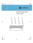
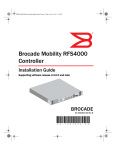
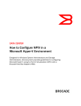
Introduction
Lock port
The lock port, compatible with laptop-style security cables, is on the side of the
case.
235mm (9.25in.)
146mm (5.75in.)
25.4mm (1.0in.)
0.73kg (1.6lbs)
Quick Installation Guide
Length
Width
Height
Weight
Motherboard firmware enables the unit to boot after either a power up or a
watchdog reset. After self-boot, the motherboard sends an “I am alive” message
into the network to be adopted and loaded with the actual runtime code. The
boot firmware on the motherboard and the firmware downloaded from the switch
can be updated using the Ethernet interface from the Wireless Controller.
Radio characteristics
The Mobility 300 is an IEEE 802.11-compliant device which contains one
802.11a radio and one 802.11b/g radio. The following table lists radio
characteristics for each radio’s compliance. The three supported 802.11g
modes are simultaneous CCK and OFDM, CCK only, or OFDM only.
External Antenna Model
Brocade Mobility 300 Access Point
(5)
®
(3)
Service information
Before using the unit, it must be configured to operate in the facility’s network
and run your applications. If you have a problem running your unit or using your
equipment, contact your facility’s Technical or Systems Support. If there is a
problem with the equipment, they will contact the Brocade Support Central.
Dimensions & weight
The Mobility 300 comprises two 802.11 radios: an 802.11b/g radio operating in
the 2.4 to 2.5GHz band and an 802.11a radio operating in the 4.9 to 5.875GHz
band.
Brocade Communications Systems, Incorporated
48VDC typical; 36-57VDC range
100mA to 165mA
250mA
-20°C to 50°C (-4°F to 122°F)
5% to 95% non-condensing
2438m (8,000ft.)
-40°C to 70°C (-40°F to 158°F)
85%
4572m (15,000ft.)
910mm (36in.) to concrete
+/-15kV air; +/-8kV contact; +/-2kV pin
UL 2043
Corporate and Latin American Headquarters
Brocade Communications Systems, Inc.
130 Holger Way
San Jose, CA 95134
Tel: 1-408-333-8000
Fax: 1-408-333-8101
E-mail: [email protected]
Operating voltage
Operating current
Peak current
Operating temperature
Operating humidity
Operating altitude (max )
Storage temperature
Storage humidity
Storage altitude (max.)
Drop (without antennas)
Electrostatic discharge
Plenum rated
European Headquarters
Brocade Communications Switzerland Sàrl
Centre Swissair
Tour B - 4ème étage
29, Route de l'Aéroport
Case Postale 105
CH-1215 Genève 15
Switzerland
Tel: +41 22 799 5640 Fax: +41 22 799 5641
E-mail: [email protected]
Technical specifications
53-1001558-02
The Mobility 300 receives all power and transfers data through the same CAT-5
cable. There is no additional power supply required.
Features
•
Supports a single antenna or dual antennas in diversity mode
•
Reverse BNC connectors for 2.4-2.5GHz and Reverse SMA connectors for
4.9-5.825GHz (Primary Antenna connectors marked • and Secondary
Antenna connectors marked ••)
•
One RJ-45 connector
•
Two redundant sets of LED indicators, top and bottom; slots next to the
bottom LEDs are for a clip on the light pipe
•
Point for a safety wire loop
•
Laptop-style lock port
•
Slots for wall mounting
The Mobility 300 has one RJ-45 connector supporting an 10/100 Ethernet port
and requires 802.3af-compliant power from an external source.
Asia-Pacific Headquarters
Brocade Communications Systems China HK, Ltd.
No. 1 Guanghua Road
Chao Yang District
Units 2718 and 2818
Beijing 100020, China
Tel: +8610 6588 8888 Fax: +8610 6588 9999
E-mail: [email protected]
The Brocade Mobility 300, a component of the Brocade Wireless Controller
System, links wireless 802.11a/b/g devices to the controller, enabling growth of
your wireless network with a cost-effective alternative to standard access points.
The Mobility 300 provides two placement options: wall and ceiling. Wall mount
slots fit onto two screws provided. Arrows on the case guide placement of the
screws. For placement above a suspended ceiling, a safety wire tie point on the
case provides for a loop of safety wire. The light pipe fits through a hole in the
ceiling tile to provide a view of the unit’s status lights.
Figure 1
Device
Mbps data rate support
Utilizing diversity
GHz
802.11a
6, 9, 12, 18, 24, 36, 48, 54 OFDM
Transmit and
receive
4.9 to 5.875
range
802.11b/g
1, 2, 5.5, 11 CCK
6, 9, 12, 18, 24, 36, 48, 54 OFDM
Transmit and
receive
2.4 to 2.5 ISM
range
Mobility 300 package contents
•
Mobility 300 with external antenna connectors (Plenum Rated)
•
Two wall mount screws
•
Two wall anchors
•
Light pipe
•
Badge for light pipe
•
Decal for badge
•
Quick Installation Guide
Description
Copyright © 2009 Brocade Communications Systems, Inc. All Rights Reserved.
The Mobility 300 (Part Number BR-AP300-5100) is an IEEE 802.11-compliant
device. The unit supports external antennas, listed under Supported Antennas,
and it requires power from any UL-listed, 802.3af-compatible Power Over
Ethernet (PoE) switch or power injector.
Brocade, the B-wing symbol, BigIron, DCX, Fabric OS, FastIron, IronPoint,
IronShield, IronView, IronWare, JetCore, NetIron, SecureIron, ServerIron,
StorageX, and TurboIron are registered trademarks, and DCFM, Extraordinary
Networks, and SAN Health are trademarks of Brocade Communications
Systems, Inc., in the United States and/or in other countries. All other brands,
products, or service names are or may be trademarks or service marks of, and
are used to identify, products or services of their respective owners.
The LEDs provide a status display indicating error conditions, transmission, and
network activity for the 802.11a (amber) radio or the 802.11b/g (green) radio.
LED indicators
The unit has LED activity indicators on the front of the case for a wall mount.
With the unit mounted above a ceiling, LEDs are at the center of an oval badge
on the ceiling; a light pipe enables viewing the back LEDs through the ceiling tile.
(4)
(6)
Task
802.11a activity LED amber
802.11b/g activity LED green
Booting
The amber LED flashes three times per
second until firmware is loaded. During
boot, 802.11a mobiles cannot
associate.
The green LED flashes three times
per second until firmware is loaded.
During boot, 802.11b/g mobiles
cannot associate.
Normal
After adoption, the amber LED is
steady or flashes with 802.11a radio
traffic.
After adoption, the green LED is
steady or flashes with 802.11b/g
radio traffic.
Error
The amber LED flashes once per
second if an error prevents the
802.11a radio from operating
normally.
The green LED flashes once per
second if an error prevents the
802.11b/g radio from operating
normally.
(1)
(2)
Installation instructions
The Mobility 300 mounts either on a wall with mounting screws or in the ceiling.
To prepare for installation, perform the following steps:
1.
Match the part number on the purchase order with the part numbers in the
packing list and on the case of the device shipped.
2.
Verify that the contents of the box include the Mobility 300 and mounting
hardware:
Item
Notes
Mobility 300
802.11a and 802.11b/g configurations with external RSMA (.11a
radio) and RBNC (.11g radio) antenna connectors. The antennae
are separate purchasable items.
Mounting Hardware: Two Phillips pan head self-tapping screws.
3.
4.
Review site survey and network analysis reports to determine the location
and mounting position for the Mobility 300.
Connect a CAT-5 cable to a compatible 802.3af power source and run the
cable to the installation site. Ensure that there is sufficient slack on the
cable to perform the installation steps.
Suspended ceiling tile (plenum) mount
Ceiling mount requires placing the Mobility 300 above a suspended ceiling and
installing the provided light pipe for viewing the status lights of the unit.
Regulatory information
Note: Notes or warnings about suspended ceiling mounts apply to all
installations where the unit is placed on suspended ceiling tile. The case has a
safety wire tie point for a standard safety wire.
All Brocade devices are designed to be compliant with rules and regulations in
locations they are sold and will be labeled as required. Any changes or
modifications to Brocade equipment, not expressly approved by Brocade, could void
the user’s authority to operate the equipment.
Caution: Brocade does not recommend mounting the Mobility 300 directly to any
suspended ceiling tile with a thickness less than 12.7mm (0.5in.) or a
suspended ceiling tile with an unsupported span greater than 660mm (26in.).
Brocade strongly recommends fitting the Mobility 300 with a safety wire suitable
for the specific installation. The safety wire should be a standard ceiling
suspension cable or equivalent steel wire between 1.59mm (.062in.) and 2.5mm
(.10in.) in diameter.
This placement requires installation of the provided light pipe for viewing the
status lights of the unit.
Ceiling mount hardware
This device is approved under the Symbol Technologies brand; Symbol
Technologies, Inc., is the Enterprise Mobility business of Motorola, Inc (“Motorola”).
Use only the approved antennas. Unauthorized antennas, modifications, or
attachments could cause damage and may violate regulations.
This device is to be used only with the Brocade wireless controller family..
Country approvals
Regulatory markings are applied to the device signifying the radio(s) are approved
for use in the following countries: United States, Canada, Japan & Europe1,2.
Please refer to the Brocade Declaration of Conformity (DoC) for details of other
country markings. This is available at http://www2.symbol.com/doc/.
Note: For 2.4GHz Products: Europe includes, Austria, Belgium, Croatia, Czech
Republic, Croatia, Cyprus, Denmark, Estonia, Finland, France, Germany, Greece,
Hungary, Iceland, Ireland, Italy, Latvia, Liechtenstein, Lithuania, Luxembourg, Malta,
Netherlands, Norway, Poland, Portugal, Slovak Republic, Slovenia, Spain, Sweden,
Switzerland, and the United Kingdom.
Wall mount
Wall mounting requires hanging the Mobility 300 along its width or length using
the pair of slots on the bottom of the unit. The Mobility 300 can be mounted onto
any plaster, wood, or cement wall surface using the provided wall anchors when
necessary. The illustration shows a lengthwise mount
Caution: The use of 5GHz RLAN’s has varying restrictions of use; please refer to the
Brocade Declaration of Conformity (DoC) for details.
Operation of the device without regulatory approval is illegal.
Frequency of operation
The use on UNII (Unlicensed National Information Infrastructure) Band 1 51505250 MHz is restricted to indoor use only.
•
•
•
•
Light pipe
Badge for light pipe
Decal for badge
Safety wire (recommended) and security cable (optional)
Safety in hospitals
Wireless devices transmit radio frequency energy and may affect medical
electrical equipment. When installed adjacent to other equipment, it is
advised to verify that the adjacent equipment is not adversely affected.
Radio frequency interference requirements – Canada
This Class B digital apparatus complies with Canadian ICES-003.
Cet appareil numérique de la classe B est conforme à la norme NMB-003 du
Canada.
Radio transmitters
This device complies with RSS 210 of Industry & Science Canada. Operation is
subject to the following two conditions: (1) this device may not cause harmful
interference and (2) this device must accept any interference received, including
interference that may cause undesired operation.
Label Marking: The Term “IC:” before the radio certification only signifies that
Industry Canada technical specifications were met.
CE marking and European Economic Area (EEA)
The use of 2.4GHz RLAN’s, for use through the EEA, have the following
restrictions:
•
Maximum radiated transmit power of 100 mW EIRP in the frequency range
2.400 -2.4835 GHz
•
France, outside usage is restricted to 2.4-2.454 GHz
•
Belgium, outside usage is restricted to 2.460-2.4835 GHz
•
Italy requires a user license for outside usage.
The use of 5GHz RLAN’s has varying restrictions for use within the EEA; please
refer to the Brocade Declaration of Conformity (DoC) for details at
.
Statement of compliance
Brocade hereby, declares that this device is in compliance with the essential
requirements and other relevant provisions of Directive 1999/5/EC. A
.
Declaration of Conformity may be obtained from
Other countries
Mexico - Restrict Frequency Range to: 2.450 - 2.4835 GHz.
Sri Lanka - Restrict Frequency Range to: 2.400 – 2.430 GHz.
Ceiling mount procedure
1.
If possible, remove the ceiling tile from its frame and place it, finished side
down, on a work surface.
(7)
Wall mount hardware
2.
•
Two Phillips pan head self-tapping screws
•
Two wall anchors
•
Safety wire (recommended) and security cable (optional)
Note: In the event that the original mounting screws are lost, the following screws
can be used instead:(ANSI Standard) #6-18 X 0.875in. Type A or AB Self-Tapping
Screw, or (ANSI Standard Metric) M3.5 X 0.6 X 20mm Type D Self-Tapping Screw
Wall mount procedure
1.
Orient the case on the wall by its width or length.
2.
Using the arrows on one edge of the case as guides,
Alignment Arrows
3.
(9)
3.
4.
5.
6.
7.
8.
9.
10.
11.
12.
If required, install a safety wire, between 1.5mm (.06in.) and 2.5mm (.10in.) in
diameter, in the ceiling space.
If required, install and attach a security cable to the unit’s lock port.
Mark a point on the upper or unfinished side of the tile.
Push the light pipe through the tile at the mark and remove the light pipe. If
necessary, use a drill to make a hole in the tile.
Snap the clips of the light pipe into the bottom of the case.
Fit the light pipe into hole in the tile from its unfinished side.
Place the decal on the back of the badge and snap the badge onto the light
pipe from the finished side of the tile.
Attach appropriate antennas to the connectors.
Attach any safety wire to the safety wire tie point or security cable to the unit’s
lock port.
Bring the tile into the ceiling space.
Plug the Ethernet cable into the the unit and to a switch with an 802.3afcompatible power source.
Verify the unit has power by observing the LEDs.
Place the ceiling tile back in its frame.
move the edge to the midline of the mounting area and mark points on the
midline for the screws.
13.
14.
At each point, drill a hole in the wall, insert an anchor, screw into the anchor
the wall mounting screw and stop when there is 1mm between the screw
head and the wall.
Supported antennas
Note: When pre-drilling a hole the recommended hole size is 2.8mm (0.11in.) if
the screws are going directly into the wall and 6mm (0.23in.) if the provided wall
anchors are being used.
(11)
Antennas are sold seperately. Contact a Brocade sales associate for these and
other available Mobility 300 antenna options.
802.11b/g antennas
If required, loop a safety wire, between 1.5mm (.06in.) and 2.5mm (.10in.)
in diameter, around the tie post and secure the loop.
Antenna option
Part number
2.4-2.5GHz, 11.2dBi 120 Degree Sector Antenna
ML-2499-11PNA2-01R
5.
If required, install and attach a security cable to the unit’s lock port.
2.4-2.5GHz, 2dBi Fixed Point Dipole Antenna
ML-2499-APA2-01
6.
Place the large corner of each of the case’s mount slots over the screw
heads.
2.4-2.5GHz, 4.6dBi OMNI Antenna
ML-2499-HPA3-01R
2.4-2.5GHz, 14.2dBi YAGI Antenna
ML-2499-BYGA2-01R
4.
7.
Slide the case down along the mounting surface to hang the mount slots on
the screw heads.
8.
Attach appropriate antennas to the connectors.
9.
Attach the Ethernet cable to the unit and to a switch with an 802.3af
compatible power source.
10. Verify the unit has power by observing that the LEDs are lit or flashing.
(8)
802.11a antennas ()
Antenna option
Part number
4.9GHz to 5.825GHz, 2dBi RSMA Dipole Antenna
ML-5299-APA1-01R
4.9GHz to 5.825GHz, 14.2dBi Patch Antenna
ML-5299-WPNA1-01R
4.9GHz to 5.825GHz, 5.9dBi OMNI Antenna
ML-5299-HPA1-01R
(10)
(13)
Contacting Brocade
FCC/EU RF exposure guidelines
Safety information
The device complies with Internationally recognised standards
covering Specific Absorption Rate (SAR) related to human exposure
to electromagnetic fields from radio devices. It is advisable to use
the device only in the normal operating position.
Remote and standalone antenna configurations
To comply with FCC RF exposure requirements, antennas that are mounted
externally at remote locations or operating near users at stand-alone desktop or
similar configurations must operate with a minimum separation distance of 20 cm
from all persons.
Power supply
This device is powered from a 802.3af compliant power source which is UL
approved.
Radio frequency interference requirements
This equipment has been tested and found to comply with the
limits for a Class B digital device, pursuant to Part 15 of the FCC
rules. These limits are designed to provide reasonable protection
against harmful interference in a residential installation. This
equipment generates, uses and can radiate radio frequency energy and, if not
installed and used in accordance with the instructions, may cause harmful
interference to radio communications. However there is no guarantee that
interference will not occur in a particular installation. If this equipment does cause
harmful interference to radio or television reception, which can be determined by
turning the equipment off and on, the user is encouraged to try to correct the
interference by one or more of the following measures:
If you have a problem with your equipment, contact Brocade Support for your
region. Contact information is available at: http://www.brocade.com/support.
When contacting Brocade support, please provide the following information:
•
Serial number of the unit
•
Model number or product name
•
Software type and version number
Brocade responds to calls by email, telephone or fax within the time limits set
forth in support agreements.
Customer Support Web Site
Brocade’s Support Central Web site, located at
http://www.brocade.com/support provides information and online assistance
including developer tools, software downloads, product manuals and online
repair requests.
Downloads
http://www.brocade.com/support
Manuals
http://www.brocade.com/support
•
•
•
Reorient or relocate the receiving antenna
Increase the separation between the equipment and receiver
Connect the equipment into an outlet on a circuit different from that to which
the receiver is connected
•
Consult the dealer or an experienced radio/TV technician for help.
Radio transmitters (Part 15)
This device complies with Part 15 of the FCC Rules. Operation is subject to the
following two conditions: (1) this device may not cause harmful interference, and (2)
this device must accept any interference received, including interference that may
cause undesired operation.
(12)
(14)