1
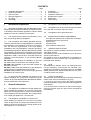
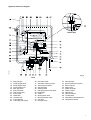
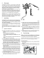
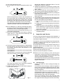
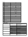
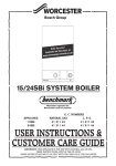
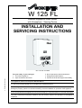
W 125 FL
Flueless Singlepoint Water Heater
with Atmosphere - Sensing Device
INSTALLATION AND
SERVICING INSTRUCTIONS
G.C. Nº 52-311-022
6 720 606 003 (01.09) AL
For your safety - if you smell gas:
1. Turn off the appliance
2. Open all windows and doors
3. Do not operate any electrical switches
4. Extinguish all naked flames
5. Contact the local Gas Region immediately
This appliance conforms to European Standard EN 26.
It is the law that all gas appliances are installed by competent persons.
The following instructions should be read carefully as the manufacturer cannot be held responsible for any
damage to property, persons or animals caused by incorrect installation or operation of the appliance.
It is recommended that the appliance be serviced annually by a competent person or the local Gas Region.
The Users Instructions should be handed to the user and the function and operation of the appliance
explained.
CONTENTS
page
1
2
3
4
5
6
1
Installation Regulations ......................................
General information ...........................................
Technical Data ...................................................
Siting the appliance ...........................................
Air supply ...........................................................
Gas supply ........................................................
2
2
5
5
5
6
Installation Regulations
page
7
8
9
10
11
12
Installation ......................................................... 6
Commissioning .................................................. 6
Inspection and Service ...................................... 7
Replacement of parts ........................................ 8
Spare parts ...................................................... 10
Fault Finding ..................................................... 11
2.3
This appliance is not suitable for external installation.
1.1 Gas Safety (Installation and Use) Regulations 1998.
All gas appliances must be installed by a competent person
in accordance with the above regulations. Failure to install
appliances correctly could lead to prosecution.
2.4 The appliance is set to provide a maximum output
of 8.7 kW and a minimum output of 4.4 kW.
1.2 The manufacturers notes must not be taken, in any
way, as overriding statutory obligations.
2.6 PRINCIPLE APPLIANCE COMPONENTS
- A low thermal capacity Gas to Water heat exchanger.
- A stainless steel main gas burner.
- A gas section.
- A water section.
- A thermoelectric safety valve.
1.3 The compliance with a British Standard does not,
of itself, confer immunity from legal obligations. In particular
the installation of this appliance must be in accordance
with the relevant requirements of the Gas Safety
(Installation and Use) Regulations 1998 (as amended),
local Building Regulations, Building Standards (Scotland)
(Consolidation), byelaws of the local Water Company and
Health and Safety Document No. 635 (Electricity at Work
Regulations 1989). It should be in accordance with the
relevant recommendations of the following British
Standards:
BS 6798:1987 Specification for Installation of gas fired
hot water boilers of rated input not exceeding 60 kW.
BS 5546:1990 Installation of gas hot water supplies for
domestic purposes.
BS 5440:2:1989 Flues and ventilation for gas appliances
of rated input not exceeding 60 kW: Air Supply.
BS 6891:1988 Installation of low pressure gas pipework
installations up to 28 mm (R1).
1.4 To ensure that the installation will perform to the
highest standards, the system and components should
conform to any other relevant British Standards in addition
to those mentioned in the instructions.
2
General Information
2.1 This appliance is available for use with natural gas.
When installing the appliance for use with natural gas,
please check 10 digit number on carton to ensure that the
correct appliance has been specified. The 10 digit number
for a natural gas appliance is 7 700 352 952.
2.2 This appliance is available for use with LPG.
When installing the appliance for use with LPG, please
check 10 digit number on carton to ensure that the correct
appliance has been specified. The 10 digit number for an
LPG appliance is 7 700 452 908.
2
2.5
The appliance has a permanent pilot.
2.7
GENERAL INSTALLATION
The appliance must be installed in the same room as the
water draw-off point.
The appliance must not be installed in a room where the
volume is less that 5m3.
The appliance must not be installed in a compartment or
roof-space or in a room which may be incorporated in a
protected shaft / stairway.
2.8
FLUE
This appliance is flueless, hence it is essential that the
correct installation requirements are satisfied. This
appliance is intended for intermittent use only, and must
not be positioned in or adjacent to a bedroom or any room
containing a bath or a shower.
2.9
SAFETY FEATURES
The Worcester W 125 is fitted with an atmosphere-Sensing
Device which must not be altered in any way.
1.) If the air in the room in which the heater is situated
becomes depleted of oxygen the pilot will be extinguished
automatically.
2.) If the flue outlet is obscured or the heat exchanger
becomes blocked again the pilot will be extinguished
automatically.
Appliance water flow diagram.
F869_086
Natural Gas
Fig. 2
L.P.G.
14
17
18
19
20
22
23
24
25
26
27
29
Pilot gas pipe
Large poppet valve
Small poppet valve
Cross-ignition bolt
Main gas valve
Pilot gas button
Gas control slide
Piezo igniter
Water filter
Hot water tap
Cold water tap
Cold water pipe (inlet)
30
31
32
35
36
37
38
39
40
41
42
43
Hot water outlet
Volumetric water governor
Temperature selector
Gas inlet pipe
Sealing screw
Inlet gas pressure test point
Diaphragm
Venturi
Slow ignition valve
Electromagnetic valve
Gas filter
Pilot gas valve
44
47
49
50
51
52
53
55
66
76
119
Pilot gas filter
Burner pressure test point
Burner injector
Main burner
Spark electrode
Thermocouple
Pilot burner
Heat exchanger
Throttle plate
Atmosphere sensing device
Temperature limiter
3
D770_046
Dimensions (in mm)
Fig. 3
1
2
3
4
5
6/1
4
Flue gas deflector
Observation window
Front cover
Output slide control
Water outlet
Cold water tap
6/2
7
8
9
11
12
Hot water tap
Temperature selector
Piezo ignitor
Water valve assembly
Gas valve assembly
Heat exchanger
3
Technical Data
Table 1 - GENERAL
Minimum rated output (Pmin)
Maximum rated output (Pn)
Rated input (Qn)
Gas rate (maximum)
Number of injectors
Injector diameter (mm)
Pilot injector marking
Burner pressure
Height (mm)
Width (mm)
Depth (mm)
Dry weight
Natural Gas
4.4 kW
8.7 kW
10.4 kW
3
1.1 m /h
8
1.1
111
9 mbar
438
270
189
7.0 kg
LPG
4.4 kW
8.7 kW
10.4 kW
0.8 kg/h
8
0.70
70
15 mbar
438
270
189
7.0 kg
Table 2 - PERFORMANCE
Maximum cold water supply inlet pressure
Minimum cold water supply inlet pressure to operate the appliance
Minimum cold water supply inlet pressure for maximum domestic hot water flow
Domestic hot water delivery with temperature control knob fully anticlockwise
12 bar (180 p.s.i.)
0.15 bar (1.5 p.s.i.)
0.6 bar (9 p.s.i.)
5 litres/minute at 25°C
temperature rise
2.5 litres/minute at 55°C
temperature rise
Domestic hot water delivery with temperature control knob fully clockwise
4
Sitting the appliance
5
Air supply
4.1 The appliance may be installed in any room with
the exception of a bedroom or any room containing a bath
or a shower.
5.1 The appliance is a flueless appliance and requires
permanent ventilation in accordance with the following
details.
4.2
5.2 A permanent air vent shall be provided. This
permanent opening shall be direct to outside air and in
accordance with the following table.
The values given are the minimum required.
The appliance is not suitable for external installation.
4.3 The appliance does not require any special wall
protection.
2
4.4 The wall must be capable of supporting the weight
of the appliance. See Technical Data – Table 1.
Ventilation Requirements cm Flueless Appliances
Room Volume
5.0 to 10.0 m
100
3
11.0 to 20.0 m
50
3
Above 20.0 m
nil
Openable window or
equivalent reqd.
3
Yes
4.5 If the appliance is to be fitted in a timber framed
building, refer to the British Gas Publication ”Guide for
gas installations in timber framed housing”.
5.3 Where an extract fan is fitted additional air vents
shall be provided. As a general guide an extra 50 cm2 of
air vent free area will be sufficient for most situations.
4.6 The following clearances must be available for
installation and for servicing:
5.4 Refer to BS 6798 and BS 5440 part 2 for additional
information.
Above
In front
Below
Right hand side
Left hand side
300 mm
600 mm
150 mm
10 mm
10 mm
4.7 The appliance must NOT be installed in a room
having a volume of less than 5.0m3.
4.8 No combustible surface must be within 75 mm of
the casing. See BS 476:4.
5
6
Gas supply
The appliance requires 1.1 m3/hr of gas. The gas meter
and supply pipes must be capable of supplying this quantity
of gas in addition to the demand from any other appliances
being served. Refer to BS 6891 for further information.
The meter governor should deliver a dynamic pressure of
20 mbar (8 in w.g.) at the appliance.
The complete installation, including the gas meter, must
be tested for soundness and purged. Refer to BS 6891.
A gas service cock must be fitted before each appliance,
a gas service cock is supplied with every appliance.
1
Important: if the 1.1 m3/hr gas rate to the appliance cannot
be reached, the specified hot water conditions will not be
achieved. This could result in customer complaints. Always
ensure that the gas supply is adequate.
The installation must be carried out by competent persons.
On delivery, check to make sure that the packaging has
not been damaged. If there is evidence of damage, contact
your supplier immediately.
Check the 10 digit code number on the appliance carton
to ensure that the correct appliance for the gas supply
has been supplied.
The code number for a natural gas appliance is 7 700 352
952. The code number for an LPG appliance is 7 700 452
908.
7.1
Appliance Installation
a) Unpack the appliance and take care to remove the
installation kit which is packed on top of the polystyrene
packing
The kit comprises of the following:
- One gas service cock with fibre washer
- One cold water isolating cock complete with fibre
washer
- One water discharge pipe complete with brass swivel
union
- Two fixing screws and wall plugs.
b) Lay the appliance on its back and pull off the Hot and
Cold water control Knobs and the Temperature control
knob. Unscrew the temperature control outer bezel to
release the casing from the appliance. Lift up the lower
front edge of the case and slide towards the top of the
heater to unhook the case from the back panel.
c) Offer up the appliance to the wall and mark the positions
for the two fixing screws. Drill two holes and fit the wall
plugs and screws.
Hang the appliance on the fixing hooks and secure the
appliance back panel to the wall through one of the
two holes located at the lower left hand side of the panel.
d) Make up the gas supply to the upper connection on
the gas control assembly using the fibre washer
provided. Fit the gas isolation cock as close as possible
to the appliance (see fig. 4, pos. 1).
e) Connect the appliance to the incoming cold water
supply via the fitting which includes the stop valve. A
fibre washer is provided (see fig. 4, pos. 2).
6
3
Fig. 4
f) Fit the brass union for the water discharge pipe to the
water control valve outlet using the fibre washer
provided. Fit the chrome plated discharge pipe to the
union and tighten sufficiently to allow the pipe to swivel
(see fig. 4, pos. 3).
g) Turn on the water supply to the appliance. Open the
stop valve on the inlet fitting to the appliance and the
open the hot and cold water taps.
Allow water to flow to vent the system and close the
taps.
h) If the appliance is not to be commissioned straight away,
re-fit the appliance casing and control knobs.
8
Comissioning
Before commissioning the appliance, the whole gas
installation must be purged and tested for gas soundness
in accordance with the current edition of BS 6891.
Important: Open all doors and windows. Extinguish naked
lights and do not smoke while purging the gas line.
Proceed as follows.
a) Ensure that the gas service cock in the gas inlet pipe
is turned off.
b) Remove the appliance casing as described in section
7 above.
c) Loosen screw A and connect a pressure gauge to the
test point. See fig. 5.
G661_016
Installation
G081_240
7
2
Fig. 5
d) Turn on the gas service cock.
e) Move the gas control slide to the ignition position. See
fig. 6.
i)
G661_013
j)
k)
Fig. 6
Observe the pilot burner. Press in the central button of
the control slider and hold depressed while pushing
the Piezo igniter button two or three times. The pilot
should light. Wait approximately twenty seconds and
then release the centre button of the control slider.
The pilot should remain alight. If the pilot does not light,
repeat the operation until a flame is established.
Note: On initial light up, or after any prolonged shut down,
the pilot may take several attempts to establish due to
the presence of air in the gas supply system.
The pilot flame should envelope approximately 5 mm
of the thermocouple head.
f) Move the control slider fully to the right for maximum
output, see fig. 7. Fully open the hot water tap. The
main burner should light.
l)
Re-light the appliance as described above. Turn the
temperature control to maximum.
Operate the appliance for at least two minutes, then
check that the burner pressure is as stated in Technical
Data – Table 1.
Turn off the hot water tap. Close the gas service cock.
Remove the pressure gauge and tighten screw D.
Re-fit the appliance casing and secure by re-fitting the
temperature control bezel.
Fit the temperature control knob and the hot and cold
water tap knobs.
On completion of the commissioning and testing of the
system, the installer should hand over the appliance to
the user with reference to the following.
1) Give the Users Operating Instructions leaflet to the
user.
2) Explain and demonstrate the lighting and shutdown
procedures.
3) Advise the user of the precautions necessary to
prevent damage to the system and to the building
in the event of the system remaining inoperative
during frost conditions.
4) Stress the importance of an annual service by a
competent person.
9.
Inspection and Service
G661_012
To ensure continued efficient operation of the appliance, it
is recommended that it is checked and serviced as
necessary at regular intervals.
Fig. 7
G661_011
g) Check the dynamic inlet gas pressure. For Natural Gas
the inlet pressure should be 20.0 mbar and for LPG
the pressure should be 28.0 mbar (Butane) or 37.0
mbar (Propane).
If the pressure is not correct then check the gas supply
to the appliance.
If the pressure is correct then turn off the hot water tap
and move the slider to the off position, see fig. 8.
Fig. 8
9.1Remove the front casing by first removing the
temperature control knob and the two water tap knobs.
Unscrew the temperature control knob bezel and
remove to release the appliance casing.
Pull forward the lower front of the casing to clear the
tap spindles and lift up the casing to unhook it from the
appliance back plate.
9.2
Turn off the gas service cock. Remove the pressure
gauge and tighten screw A, see fig. 5.
h) Loosen screw D and connect the pressure gauge to
the test point, see fig. 9.
G662_042
The frequency of servicing will depend upon the particular
installation conditions and usage but in general once a
year should be adequate.
It is the law that any service work must be carried out by a
competent person such as British Gas or other Corgi
registered personnel.
Before commencing any service operation turn off the gas
supply at the main gas service cock
Carry out the service operation as follows.
Fig. 9
Heat Exchanger
Inspect and clean the heat exchanger flueways as
necessary.
To remove the heat exchanger, isolate the appliance
from incoming cold water supply at the inlet cock. Open
the taps to release any remaining water pressure and
drain the appliance.
Undo the brass union nut on the pilot air supply pipe
and withdraw the pipe from the air inlet collector.
Disconnect the push on terminals from the overheat
thermostat at the top of the heat exchanger.
Pull out the retaining clips at the inlet and outlet
connections on the water control body, and spring out
the copper inlet and outlet pipes from the control body.
7
Take care not to damage the two ‘O’ ring seals.
Unscrew the large heat exchanger retaining screw,
located at the rear of the combustion chamber just
above the burner blades, and lift clear the heat
exchanger assembly.
In hard water areas it may be necessary to descale the
heat exchanger body. A proprietary brand of descaler
should be used. Fill the heat exchanger with this
solution and leave until the solution stops bubbling.
Drain and thoroughly wash out the exchanger with clean
water.
Warning: Acid/water solutions must be used with
extreme caution. Take care not to splash on to the skin
or into the eyes. Wash any affected areas with large
amounts of cold water and seek medical advice.
Re assemble in reverse order taking care to locate the
heat exchanger on the two support hooks formed in
the appliance back plate.
9.3Pilot Assembly
Remove the appliance casing as described above.
Remove the pilot air supply pipe as described above.
Undo the union connection on the pilot gas pipe at the
pilot body.
Undo the two screws securing the pilot body to the
burner front rail and withdraw outwards and upwards
away from the pilot gas pipe.
Note: take great care to retain the pilot injector located
between the end of the pilot gas pipe and the inside of
the pilot body.
Inspect, clean and adjust as required.
Re-assemble in reverse order taking care to locate the
pilot injector correctly.
9.4Main Burner
Remove the appliance casing and pilot assembly as
described in sections 9.1 and 9.3 above.
Slacken the pilot pipe union at the gas valve end and
swing the pilot pipe to the left.
Undo the brass union nut holding the burner assembly
to the gas valve body.
To remove the assembly from the combustion chamber
it must be turned upside down. Proceed as follows.
Raise the front edge of the burner up into the
combustion chamber turning over away from the front.
Once the burner is upside down it can be withdrawn
from under the combustion chamber, the union passing
through cut-away in the front of combustion chamber.
Inspect and clean as required. Check the union joint
ring and replace if required.
Replace in reverse order taking care that the locating
pin in the rear of the burner locates with the slot in the
rear frame.
9.5
8
Final Inspection
Turn on the gas supply at the main gas service cock
and check for gas soundness in accordance with the
current edition of BS 6891 while the appliance is
running.
Re-commission the appliance as described in section
8.
10
Replacement of Parts
The law requires that any service work must be carried
out by a competent person such as British Gas or other
Corgi registered personnel.
Before commencing any service operation turn off the gas
supply at the main gas service cock.
10.1 Pilot Burner / Injector
Remove the appliance casing as described in section
9.1 above.
Remove the pilot assembly pipe as described in section
9.3 above.
Remove the retaining clip, holding the ignition electrode
and thermocouple to the body, from the side of pilot
burner body to release the electrode and thermocouple.
Fit the new injector and/or pilot burner in reverse order.
10.2 Ignition Electrode / Thermocouple
Follow the instructions given above in section 10.1 and
replace the faulty components.
10.3 Main Burner
Remove the appliance casing and pilot assembly as
described in sections 9.1 and 9.3 above.
Remove the main burner as described in section 9.4.
Replace the burner in reverse order taking care that
the locating pin in the rear of the burner locates with
the slot in the rear frame and that the union joint ring is
correctly positioned.
10.4 Piezo Spark Generator
Remove the front casing as described in section 9.1
above.
Pull forward the lower front of the casing to clear the
tap spindles and lift up the casing to unhook it from the
appliance back plate.
Unscrew the locking ring from the front of the Piezo
unit and withdraw the unit backwards through the
mounting plate. Pull off the two push on terminals and
discard the old unit.
Fit the new unit in reverse order taking care to locate
the unit on the small retaining peg. Also ensure that
the earthing wire is sprung into the hole in the mounting
frame.
10.5 Heat Exchanger
Remove the heat exchanger as described in section
9.2 above.
Remove the overheat thermostat and pilot air inlet
collector and fit to the new heat exchanger.
Ensure that two new ‘O’ ring seals are fitted to the inlet
and outlet pipes. Re-assemble in reverse order taking
care to locate the heat exchanger on the two support
hooks formed in the appliance back plate.
10.6 Water Control Assembly
a) Remove the front casing as described in section 9.1
above.
b) Isolate the appliance from incoming cold water
supply at the inlet cock.
Open the taps to release any remaining water
pressure and drain the appliance.
c) Remove the water discharge pipe.
d) Undo the union connection on the water isolating
cock.
e) Pull out the retaining clips at the inlet and outlet
connections on the water control body, and spring
out the copper inlet and outlet pipes from the control
body. Take care not to damage the two ‘O’ ring seals.
f) Pass a screwdriver through the hole in the centre of
the lower edge of the fascia panel and slacken the
first of the two retaining screws. The second retaining
screw is located at 90 degrees on the right and is
accessed from the side.
g) With both screws slackened the water control
assembly can be withdrawn downwards away from
the gas valve body.
h) Replace in reverse order.
10.7 Gas Valve
a) Remove the burner as described in section 9.4 above
b) Remove the water control assembly as described in
10.6 above.
c) Undo the gas inlet union at the rear of the gas valve
d) Access the two gas valve retaining screws from the
left hand side and remove.
e) Withdraw the gas valve, complete with slider
controls, from the appliance.
f) Remove the Piezo igniter.
g) Remove the control fascia by taking out the four fixing
screws and lifting clear complete with slider knob.
h) Prise out the slider bar and remove the two screws
retaining the control frame and lift clear.
i) Assemble the Piezo igniter, slider bar, control fascia
and pilot pipe to the new gas valve.
j) Re-assemble the gas valve, burner and water control
assembly in reverse order.
10.8 Final Inspection
Turn on the gas supply at the main gas service cock
and check for gas soundness in accordance with the
current edition of BS 6891 while the appliance is
running.
Re-commission the appliance as described in section
8.
9
11
Spare Parts
Fig. 10
10
Parts List
Description
Propane
Natural Gas
1
Front Cover
8 705 411 730
2
Temp. Control Knob
8 702 000 219
3
Flue gas Deflector
8 705 505 249
4
Heating Body
8 705 406 248
Main Burner Assembly
8 708 120 239
8 708 120 352
8 708 202 130
8 708 202 157
7
Main Burner Injector
Gas Valve Assembly
8 707 011 786
8 707 011 100
8
Slide Assembly & Guide plate
8 701 000 105
9
Piezo-Igniter
8 748 108 023
10
Cross Ignition bolt
11
Magnetic Unit
8 707 201 015
12
Thermocouple
8 707 202 039
13
Temperature Limit Thermostat
8 707 206 132
14
Gas Inlet Washer
8 700 103 014
15
16
Pilot Burner
Pilot Injector
17
Pilot Tube
8 700 707 334
18
Spark Electrode
8 708 107 002
19
Ignition Lead
8 704 401 022
20
Pilot Air Collector
21
Pilot Air Inlet Pipe
8 700 705 527
22
Water Valve Assembly
8 707 002 630
23
Water Valve Cover
8 705 500 101
24
Cover Repair Kit
8 700 306 098
25
Diaphragm
8 700 503 050
26
Water Strainer
8 700 507 001
27
Valve spindle
8 708 500 277
28
Selector Screw
8 708 500 233
29
Venturi
8 708 205 275
5
6
12
---------------
8 703 407 027
8 708 105 327
8 708 105 320
8 708 200 138
8 748 200 120
8 701 302 074
8 701 302 082
Fault Finding
Problem
Incorrect water temperature
Cause
Solution
Incorrect gas rate
Check the gas supply to appliance gas service cock
Open the gas service cock
Check the burner pressure
Check the inlet pressure
Water section sticking or faulty
Clean or replace
Incorrect water flow rate
Incoming supply valve closed
Open supply valve
Low water pressure
Check if water pressure is above 0.15 bar
Water section sticking or faulty
Clean or replace
Noise
Scale in heat exchanger
Descale and service
High gas rate
Check the burner pressure
Low water flow rate
Check the water flow rate
Pilot flame will not stay alight
No gas supply
Connect gas supply
Gas service cock closed
Open gas service cock
Air in gas line
Purge the line
Pilot injector blocked
Clean or replace the injector
No spark
Clean or replace the electrode, piezo unit or cable
Main burner will not light
Gas pressure low
Check the inlet and burner pressure
Gas service cock partially closed
Open the gas service cock
Low water rate
Check the water rate
Water section diaphragm faulty
Replace the diaphragm
Gas valve faulty
Replace the gas valve
Buner extinguishes while in operation Oxygen deficiency sensor activated Ventilate the room and re-ignite the appliance some
minutes later. If it happens again, contact a Corgi
registered technician.
11
Worcester Heat Systems Limited, Cotswold Way, Warndon, Worcester WR4 9SW.
Telephone: (01905) 754624. Fax: (01905) 754619
This booklet is accurate at the date of printing but will be superseded and should be disregarded if specifications and/or appearances are
changed in the interests of continued improvement.
All goods sold are subject to our official Conditions of Sale, a copy of which may be obtained on application
6 720 606 003 (01.09) AL