1
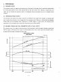
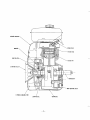
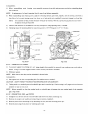
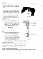
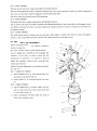
ROBIN AMERICA, INC.
ROBIN TO WISCONSIN ROBIN
ENGINE MODEL CROSS REFERENCE LIST
ROBIN
WISCONSIN ROBIN
SIDE VALVE
EY 08
EY15
EY 15V
EY20
EY20V
EY23
EY28
EY35
EY40
EY45V
EY2 1
EY44
EY 18-3
EY25
EY27
W 1-080
WI-145
W1-145V
W1-185
W1-185V
W 1-230
W 1-280
Wl-340
W1-390
W 1-450V
EY21W
EY44W
EY 18-3W
EY25W
EY27W
v
EH11
EH12
EH15
EH17
EH2 1
EH25
EH30
EH30V
EH34
EH34V
EH43V
WO1-115
wo1-120
WO1-150
WO1-170
wo1-210
WO 1-250
WO 1 -300
WOI-3oov
WO 1-340
WO1-340V
WO 1-43OV
TWO CYCLE
EC13V
WT1-125V
DIESEL
DY23
DY27
DY30
DY35
DY4 1
WRD 1-230
WRD 1-270
WRD1-300
WRD1-350
WRD1-410
CONTENTS
Section
Title
.
Page
1 SPECIFICATIONS
............................................
1
2. PERFORMANCE
............................................
2
2.1 .
2.2 .
2.3
.
Maximumoutput . . . . . . . . . . . . . . . . . . . . . . . . . . . . . . . . . . . . . . .
Continuous Rated Output . . . . . . . . . . . . . . . . . . . . . . . . . . . . . . . . .
Maximum Torque and Fuel Consumption Ratio a t Max Output . . . . . . . .
.
3. FEATURES
...............................................
4 . GENERALDESCRIPTION
4.1 .
4.2 .
4.3 .
4.4 .
4.5 .
4.6 .
4.7 .
4.8 .
4.9 .
4.10 .
4.11 .
4.12 .
4-13.
4- 14
.
4.15 .
4- 1 6 .
5.5 .
5.6 .
.
.
6-3.
3
4
4
6
6
6
6
6
6
6
6
7
7
7
7
7
7
7
............................................
8
Mounting . . . . . . . . . . . . . . . . . . . . . . . . . . . . . . . . . . . . . . . . . . . .
Ventilation . . . . . . . . . . . . . . . . . . . . . . . . . . . . . . . . . . . . . . . . . . .
Exhaust Gas Evacuation
Fuel
System
Power
Transmission to Driven
Machines
Wiring
8
8
8
8
..................................
..........................................
.......................
..............................................
6 DISASSEMBLY and REASSEMBLY
8 1
6-2.
...............
Sectional View of Engine . . . . . . . . . . . . . . . . . . . . . . . . . . . . . . . . . .
Crankcase . . . . . . . . . . . . . . . . . . . . . . . . . . . . . . . . . . . . . . . . . . .
Main
Bearing
Cover
.....................................
Crankshaft . . . . . . . . . . . . . . . . . . . . . . . . . . . . . . . . . . . . . . . . . . .
ConnectingRod and Piston . . . . . . . . . . . . . . . . . . . . . . . . . . . . . . . .
Camshaft
...........................................
Cylinder and Cylinder Head . . . . . . . . . . . . . . . . . . . . . . . . . . . . . . .
Valve
Arrangement
.....................................
Balancer . . . . . . . . . . . . . . . . . . . . . . . . . . . . . . . . . . . . . . . . . . . . .
Governor . . . . . . . . . . . . . . . . . . . . . . . . . . . . . . . . . . . . . . . . . . . . .
Cooling . . . . . . . . . . . . . . . . . . . . . . . . . . . . . . . . . . . . . . . . . . . . .
Lubrication . . . . . . . . . . . . . . . . . . . . . . . . . . . . . . . . . . . . . . . . . . .
Ignition . . . . . . . . . . . . . . . . . . . . . . . . . . . . . . . . . . . . . . . . . . . . .
Carburetor . . . . . . . . . . . . . . . . . . . . . . . . . . . . . . . . . . . . . . . . . . .
Air Cleaner . . . . . . . . . . . . . . . . . . . . . . . . . . . . . . . . . . . . . . . . . . .
Selenium Rectifier . . . . . . . . . . . . . . . . . . . . . . . . . . . . . . . . . . . . . .
5.lNSTALLATlON
5.1 .
5.2 .
5.3.
5.4 .
of ENGINECONSTRUCTION
2
2
2
..............................
Preparations
and
Suggestions
...............................
SpecialTools . . . . . . . . . . . . . . . . . . . . . . . . . . . . . . . . . . . . . . . . .
DisassemblyandReassemblyProcedures
.......................
8
9
10
10
10
11
7 . MAGNETO
7.1 .
7.2 .
7.3 .
7.4 .
...............................................
18
Magneto . . . . . . . . . . . . . . . . . . . . . . . . . . . . . . . . . . . . . . . . . . . . .
Breaker PointAdjustment . . . . . . . . . . . . . . . . . . . . . . . . . . . . . . . . .
Timing
Adjustment
.....................................
Magneto
Service Instructions . . . . . . . . . . . . . . . . . . . . . . . . . . . . . . .
18
18
18
8. GOVERNOR ADJUSTMENT
9.CARBURETOR
...................................
.............................................
19
21
22
Operation and Construction . . . . . . . . . . . . . . . . . . . . . . . . . . . . . . . .
22
Disassembly
and
Reassembly
. . . . . . . . . . . . . . . . . . . . . . . . . . . . . . . . . 23
Adjustment . . . . . . . . . . . . . . . . . . . . . . . . . . . . . . . . . . . . . . . . . .
23
9.1 .
9.2 .
9.3
.
.
11. TROUBLESHOOTING
10 RUN-INOPERATION
11.1 .
11.2 .
11.3
11.4 .
11.5 .
11.6.
.
OF ENGINE after REASSEMBLY
...............
.......................................
StartingDifficultes . . . . . . . . . . . . . . . . . . . . . . . . . . . . . . . . . . . . . .
EngineMisses
.........................................
EngineStops . . . . . . . . . . . . . . . . . . . . . . . . . . . . . . . . . . . . . . . . . .
Engine
Overheats
......................................
EngineKnocks
........................................
EngineBackfiresThroughCarburetor
.........................
25
26
26
27
27
27
28
28
.
. . . . . . . . . . . . . . . . . . . . . . . . . . . . . . . . . . 29
13. MAINTENANCE and STORING . . . . . . . . . . . . . . . . . . . . . . . . . . . . . . . . . 35
12 CHECKS and CORRECTIONS
.
13.1
13.2 .
13.3 .
13.4
13.5 .
13.6
13.7 .
.
.
. . . . . . . . . . . . . . . . . . . . . . . . . . . . . . 35
. . . . . . . . . . . . . . . . . . . . . . . 35
Daily ChecksandMaintenance
Every20HoursChecksandMaintenance
Every 50 Hours (10 days)ChecksandMaintenance
Every 100-200 Hours (Monthly) ChecksandMaintenance
Every 500-600 Hours(Semianual)ChecksandMaintenance
Every1000Hours (Yearly) ChecksandMaintenance
...............
Preparation for Long Abeyance . . . . . . . . . . . . . . . . . . . . . . . . . . . . .
. . . . . . . . . . . . . . . . 35
. . . . . . . . . . . 35
..........
36
36
36
1. SPEC1 FICATIONS
-1-
2. PERFORMANCE
2-1MAXIMUMOUTPUT
The maximum output of an engine is such standard power as developed by that engine, after its initial run-in period witha1
the moving parts properly worn-in, when operating with the fully open throttle
valve. Therefore, it follows that
enginemaynotdevelopthismaximumoutputinthebeginning,becausemovingpartsarenot
in aproperly
a nev
w0rn-h
condition.
2-2 CONTINUOUSRATEDOUTPUT
The continuous rated output of an engine
is such power as developed by that engine when running at an optimum
speec
most favorable from the point of view of engine life and fuel consumption ratio. Therefore, it follows that when designing i
EY33-2 or EY44-2 engine, as a primemover,thecontinuouspowe
driving systemforanymechanism,withamodel
requirement of that mechanism must be kept below the continuous rated output specified.
2-3 MAXIMUM TORQUE AND FUEL
CONSUMPTION RATIO AT MAX. OUTPUT
The maximum torque of an engine is that driving torque of the driving shaft at which the engine is driving an external load
while the engine is developing its max. output. The fuel consumption ratio at max. output
is that fuel consumption ratio o
an engine while that engine is running at the max. output.
PERFORMANCECURVE
Model EY33-2
( )for
B
type
RECOMMENDED OPERATING SPEED RANG
a
I
7
HP
5
M A X . TORQUE
125112 5
I
124)12
1.7(3.4)
-I
-~
1.6(3.2)
ft"b (23J11.5--
I
kg-rn
1.5 ( 3 . 0 )
320
300
280
2000
(1OOO)
3500
-
3000
2500
112501
115001
rpm
-2-
11750)
g/ P.h
3. FEATURES
1.
A compact, lightweight, and highly durable 4cycle aircooled EYseries with high output, embodying ingenious design
and advanced machining techniques.
2.
3.
Simple construction, good appearance, plus easy start-up.
Smooth speed control functions
of governorguaranteesstableoperationundervariousloadconditionsoverawide
range of applications.
4.
Economical advantage with minimized fuel consumption.
5.
Since power can be taken in any direction simply by pulling the belt, and the feed and drain oil work can also be done
easily in two directionsof engine, the engineis easily coupled with operating machines.
6 . The use of dynamic balancer reduces vibrations to such an extantas in a two-cylinder engine.
PERFORMANCE CURVE
Model EY44-2
( ) f o r B type
R E C O M M E N D E D O P E R A T I N G SPE
11
10
HP
9
0
7
6
(33) 16.5
2.3(4.6)
(32) 16
2.2(4.4)
(31) 15.5
2.1(4.2)
tt-lb
2000
2500
3000
(1000)
(1250)
(1500)
m
p-r
-J-
3500
(1750)
kg-m
/-
FLYWHEEL(COOLI~GFAN)
I
\
LIGHTING COIL
CRANKCASE
-4
-
SEl
-5-
4-2 CRANKCASE
The crankcase is made of aluminum die-cast and separable on driving shaft side with main bearing cover assembled.
Provided on blower side are two ball
bearings, each supporting the crankshaft and camshaft.
4-3 MAINBEARING
COVER
The aluminum die-cast main bearing cover
on the driving shaft side allows easy access
to the engine interior for inspection
simply by removing it. The’fange and boss permit direct coupling of operating machines such as generators, pumps, etc.
The oil inlets whichalso serve as oil gauges can be mounted on driving shaft side of Models EY33-2B and E Y 4 4 - 2 B .
The force-fit balancer shaft and balancer holder mounting boss assure easy mounting of the balancer mechanism.
4 4 CRANKSHAFT
The crankshaft is machined from carbon steel forging with an induction hardened crank pin. The breaker cam is provided on
blower side, while crankshaft gear and balancer gear are force-fit on driving side.
4-5 CONNECTING ROD and PISTON
The connecting rod is machined from aluminum alloy forging, and forged alloy itself serves as bearing metal at both ends.
(Model EY44-2 employs aluminum metal on the large end.)
An oil scraper is provided on the large endforthepurpose
ofsplashinglubricatingoil.Thepiston
is machinedfron
aluminum alloy casting and provided with grooves for two compression rings, one oil rings, and one skirt ring.
The EY44-2 piston has an offset structure at the piston pin center so as to reduce striking sound of piston.
4-6 CAMSHAFT
Thecarbonsteelforgingcamshaftincorporatesintegralintakeandexhaustcamsplusaforce-fitcamgear.
The B-typ
camshaft also serves as driving shaft and it is driven at half the crankshaft speed.
4-7 CYLINDER and CYLINDERHEAD
The cylinder is made of special cast iron and provided with many fins for assuring excellent cooling effects. The
cylinda
head is made of aluminumalloycasting.TheRicardotypecombusionchamberwithasufficientareaassures
hil
combusion efficiency. The spark plug is tilted to facilitate fuel tank mounting.
4-8 VALVEARRANGEMENT
Theexhaust
valve is positioned in theupstreamofthecolling
air so thatit
is intensivelycooled
downforimprov
durability of engine.
4-9 BALANCER
An unbalanced inertia force produced due to crankshaft and piston connecting rod in the vertical and lateral direction:
balanced bybalancerwhichrotatesat
a ratioof
1: 1 in the direction opposite to crankshaft,
unbalanced inertia force are reduced.
-6-
so that vibrations due
4-10
GOVERNOR
The centrifugal flyweight type governor assures constant-speed operation at selected speed, irrespective
of load fluctuations.
4-11 COOLING
The cooling fan which also serves as a flywheel forcily feeds cooling air to the cylinder head with the aid of cylinder baffles
and head cover.
4-12 LUBRICATION
Therotatingand
slidingpartsarelubricatedbyscoopingandsplashingoilincrankcasewith
oil scraperattachedto
connecting rod.
4-13 IGNITION
The ignition system is of flywheel magneto type with ignition timing set at 23' before TDC. The magneto is composed of a
flywheel,anignitioncoil,abreaker,andlighting(charging)coil.Theflywheel(servingalso
as afan)
is mountedon
crankcase, while the other elementsare directly assembled in crankcase (For details, refer to the MAGNETO section).
4-14
CARBURETOR
A horizontaldraftcarburetor
is employed.Itssettinghasbeencarefullyafterthoroughteststoachievebeststart-up,
acceleration, fuel consumption, output, and other performance. For other details,
see the CARBURETOR section.
4-15AIRCLEANER
An impinge type semi-wet
air cleaner catches dust particles in the air by means
of felt in dust case. The air is then cleaned
by passing through a filter element.
4-16SELENIUMRECTIFIER
The selenium rectifier serves to rectify the AC current generated by AC charging coil of magneto into DC current to charge
battery when a starting motor is combined.
-7-
5. INSTALLATION
Since the installation method affects the
service life, ease of maintenance, frequency of check and reapir, and operating
costs of engine, the following contents should be carefully examined before installing your engine.
For details, referto the separate “SALES MANUAL”-Engineering Information-.
5-1 MOUNTING
When installing the engine, its mounting position, coupling conditions with operating machines, and anchoringor supporting
methods must be carefully examined. Particularly when determining its mounting position, due care should be taken to
assure the convenience of such routines as replenishment and checking of fuel and oil, checking of spark plug and breaker
points, maintenance of air cleaner, and oil drainage.
5-2 VENTILATION
The engine must be supplied with .fresh air for cooling and fuel combustion. If engine is operated with a cover or in a small
room, the engine room
is heated, causing vapor lock, deterioration of oil, increase of
oil consumption, power reduction,
no longer.
seizure, loss of engine life, and thus proper engine operation can be expected
It is therefore necessary to provied a cooling air duct and a baffle plate for the purpose of preventing insufficient circulation
of heated air after cooling engine and or temperature-rise of operating machines.
The temperature of engine compartment should be kept below 4OoC even in mid-summer.
5 3 EXHAUST GAS EVACUATION
Since the exhaust gas from engine
is toxic, it must be exhausted outside if engine is operated indoors.
As the output power of an engine is considerably influenced by the length of exhaust duct, its diameter must be increased in
proportion to its length.
5-4 FUELSYSTEM
When fuel tank is separated from engine, it must be located
so that its bottom surface lies within 5-50cm
(2”-20”) above
the fuel joint of carburetor. If the fuel tank is installed too low, fuel is not fed properly, and if it is too high, the carburetor
may overflow.
For fuel piping, carefully examineit for heat conductivity, diameter, bending, andleakage through fittings so as to eliminate
air lock and vapor lock.
It is recommended to minimize piping length. The standard ID of fuel pipe is 4-5mm
(5,2”-13/64“).
5-5 POWER TRANSMISSION to DRIVEN MACHINES
5-5-1 BELT D R I V E
Be carefulwiththefollowing
items.
*Ilse a V-belt rather than a flat belt.
*Set the driving shaft of engine and the driven shaftof driven machine in paralled with each other.
*Align the driving pulley of engine and the driven pulley of driven machine correctly with each other.
*Mount the driving pulley as nearer to the engine as possible.
-8-
5-6 WIRING
a
JIS CB104 female terminal
-e JIS CA104 male terminal
-@
-
JIS LA 104 or LA108 plate terminal
The dotted parts are not supplied with the engine.
"
"
"
5-6-1 ROPE STARTINGENGINE
MAGNETO
_""
.
'-N
/
BUZZER
(6"- 8 W )
SPARKPLUG
Fig. 5-6-1
LAMP
(12V. 15W)
5-6-2 ENGINEwithSTARTINGMOTOR
MAGNETO
LA 104
-g
-:
6. DISASSEMBLY and REASSEMBLY
6-1 PREPARATIONS and SUGGESTIONS
1 ) When disassembling engine, carefully note mounting positions and methods of respective parts in order
to be able to
reassemble them correctly. Tag parts, if there is a possibility of confusion.
2 ) Prepare several boxes to keep parts belonging to respective groups together.
3 ) In order to prevent missing or misplacing, group related parts together, tentatively assembling them immediately after
disassembling each sub-assembly.
4 ) Carefully handle parts, and clean them with washing oil after disassembling.
5 ) Use correct tools in correct ways.
6 ) Standard tools to be prepared for disassembling.
a)
b)
Work Bench
'
Washing Pan
c)
Disassembling Tools
d)
Washing Oil (Kerosene or Gasoline), Mobile Oil
e)EmeryPaper,Cloth
7 ) Drain fuel and oil without fail before disassembly.
To drainoil,unscrewtheoildrainpluglocatedonthesideofcrankcaseoncarburetorsidebyturningit
counter-clockwise.
8 ) Clamp cylinder head, cylinder main bearing cover, connecting rod, spark plug, and flywheel with specified torque when
reassembling them.
9 ) Replace all the packings and gaskets with new ones when reassembling.
I O ) Wash parts with new gasoline o r washing oil, and blow them with compressed air before reassembling.
1 1 ) Apply mobile oil to the rotating and sliding parts.
12) Be careful not to contaminate parts with dust during reassembling.
13) Tighten bolls, nuts, and screws to correct torque readings specified. I f small screws are tightened too strongly, they may
be broken.
signs of abnormal friction, noises, or looseness.
14) After reassembling, turn the moving parts by hand, and check them for
6-2 SPECIALTOOLS
.. .
""
c"
"
- ."
-..
~
"
"
3
"
V A L V E SPRING COMPRESSOR
Fig. 6-2
-1 0-
I
209 99010 07
(Y790-350)
001 65085 00
Flywheel Puller
Bolt
I 1
Valve Spring Compressor
209 9901 1 07
(Y790-282)
Valve Seat Cutter (45”)
209 9901 2 07
1
(H640-118)
1
Pilot Stem
6-3 DISASSEMBLY and REASSEMBLYPROCEDURES
6-3-1 FUEL TANK and TANK BRACKET
1)
Disconnect fuel pipe between fuel strainer and carburetor from carburetor.
2)
Detach fuel tank from its mounting bracket (8mm nut
X
4).
3 ) Detach bracket and head cover from cylinder head (8mm bolt
X
2).
In reassembly;
It is recommended to replace fuel pipe with new one before reassembly.
CAUTION:
REPLACE FULE PIPE WITH NEW ONE ONCE EVERY YEAR.
6-3-2 BLOWER HOUSING and CYLINDERBAFFLE
1)
Disconnect primary coil wire from stop button wire.
2 ) Take off muffler cover and blower housing from
crankcase. and baffle from cylinder head.
(6mm bolt
3)
X
36mm screw
X
4).
Remove baffle from cylinder block. (6mm screw
. 6-3-3
X
2).
AIRCLEANER
1) Remove
air cleaner cover and element.
2) Detach bottom plate of air cleaner from carburetor by loosening two 6mm bolts.
(Also, detach the choke button from the carburetor chocke lever)
3)
Disconnectbreatherpipe.
In reassembly;
Put air cleanerelement
in gasolineandsufficientlywashitwhileshakinguntildust
is completelyremoved.After
oil (gasoline and mobile
washing, dry the element thoroughly and apply mixture
of 4:1), before
oil mixed at a ratio
reassembly.
6-3-4 MUFFLER
Remove muffler from cylinder part of crankcase (8mm nut
6-3-5 GOVERNORLEVER
1)Detachgovernor
X
2, 8mm bolt
X
2).
and CARBURETOR
lever fromgovernorlevershaft(6mmnut
X
1 ).
2) Detachgovernorrodandrodspringfromcarburetor.
3)
Removecarburetorfromcylinder
par‘t of crankcase (EY33-2: 6mmnut
In reassembly:
Referto
“8. GOVERNOR ADJUSTMENT”section.
-1 1-
X
2 , EY44-2: 8mmnut
X
2).
6-3-6 STARTING PULLEY and FLYWHEEL (magneto)
Remove 3 piecesmountingboltstodetachstarting
pulley from flywheel.
Remove flywheel from crankshaft.
nut,and
18mm
or box wrench into an
Insert a socket wrench
give thewrenchasharpblowwithasoft
hammer. Remove nut and spring washer.
AttachflywheelpullertoflywheelasshowninFig.
6-3-1, andturncenterboltclockwiseuntilflywheel
becomes loose enough to be removed.
Disconnecthightensioncable
of ignitioncoilfrom
Fig. 6-3-1
disconnect
crankcase,
plug,
spark
from
clip
cable
and
then, remove ignition coil from crankcase
(6mm X 25mm screw
X
2).
Remove cable clip from lighting coil cable, and detach lighting coil from crankcase (6mm
X
30mm screw
x 2).
Remove breaker cover, and then remove contact breaker and condenser from crankcase.
In reassembly ;
Refer to “7-2 BREAKER POINT ADJUSTMENT” and “7-3 TIMING ADJUSTMENT”.
6-3-7 CYLINDERHEAD
1)
and SPARKPLUG
Detach spark plug from cylinder head.
2) Detach cylinder head and gasket from cylinder by loosening lOmm nut.
In reassembly;
1)
Remove carbon from combustion chamber and also remove dirt from the vicinity of cooling fins of cylinder head.
Check head face for distortion. Replace cylinder head, if needed.
2)Replacegasketwithnew
3)
one.
Clamping torque of cylinder head is 450-500
kg-cm (32.5-36 ft-lbs).
NOTE: Leavespark plug detached temporarily to facilitate engine rotation during timing adjustment. When mounting
finally, tighten it 250-300 kg-cm (18-21.7 ft-lbs).
6-3-8 INTAKE and EXHAUST VALVE
Detachinnerandoutertappet
cover fromcylinder
block (6mm bolt x 2).
Detach retainer locks and valves by Lifting valve spring
using a valve spring retainer. Proceed
bothforintake
valve andexhaust
in the same way
valve. (Fig. 6-3-2)
Then, remove valve springs and spring retainers.
CA 1JTION:
TAPPET
DO NOT DAMAGE GASKET SURFACE OF
C H A M B E R WITH THE COMPRESSOR
TOOL.
Fig. 6-3-2
- 1 2-
-
In reassembly;
1) Clean carbon and gum deposits from the
valves, seats, ports and valve stem holes.
2)
Replace valves, if badly burned, pitted or warped.
3)
Correct the valve seat by using 45" seat cutter tool as illustrated in
1.2-1 S m m (.04-.05
4)
Fig. 6-3-3. The seat should be
finished to
inch) in width.
Cylinderblockshouldbereplaced
if valve stemclearancebecomesexcessive.'Referto
Fig. ..-' 4 for
clearance specifications and proper assembly.
After correcting valve seats, lap valves in place until a uniform ring
5)
a hotsolution
valve. Clean valves, andwashblockthoroughwith
will show entirely around the face
of soapandwater.
of the
Wipecylinderwalls
with clean lint free rags and light engine oil.
CAUTION: DO N O T ASSEMBLE
V A L V E SPRINGS ANDSPRINGRETAINERS
AFTER ADJUSTING
TAPPET CLEARANCE.
Fig. 6-3-3
VALVE and VALVESTEMHOLECLEARANCE
4 5"
A - VALVE FACE ANGLE
I
I
I
I
B - SEAT ANGLE
-
(::!;::)
8 DIA.
+:.036
INTAKE
8 DIA.
-0 0 3 0
-0:oss
(
3168'
:313rr)
EXHAUST
8 DIA.
;:1
(
::fi::)
INTAKE
0.030-0.09 1 (.0012"-.0036")
EXHAUST
0.090-0.146
C - GUIDE INSIDE DIA.
D
45"
VALVE STEM DIA.
MAXIMUMALLOWABLE
CLEARANCE BETWEEN C a n d D
Fig. 6-3-4
-1 3-
(.0035"-,0057")
I
6) ADJUSTING TAPPET CLEARANCE (Fig. 6-3-5)
*
Rotate
crankshaft
until
tappet
position,hold
is in
its
lowest
valve downandinsertfeelergauge
between valve andtappetstem.Theclearancefor
both intake and exhaust, with engine cold.
0.13-0.17mm
*
(0.0051”to 0.0067“)
If clearance is less than specified, slightly grind valve
stem and measure it again.
*
If clearance is largerthanspecified,sink
valve seat
to adjust clearance.
* Afterclearanceadjustment,assemble
valvesprings
in placewith
and valve retainers, and secure them
retainerlocks.Checktappetclearance
Fig. 6-3-5
again for
proper adjustment by turning crankshaft.
6-3-9 CYLINDER
BLOCK
Detachcylinderbylooseningone8mmandfivelOmm
nuts.
In reassembly;
Remove from upper surfaceof cylinder, carbon deposit
R I N G GUIDE
HOLDER
\
which
otherwise
may
damage
piston
when
piston
moves.
lnsert
doubling
a
plate
between
piston
skirt
and
crankcase, and set piston to the cylinder center so that
piston will not move easily. (Fig. 6-3-6).
.
Stagger the piston ring gaps 90° apart around piston.
Apply oil to piston ring and cylinder walls sufficiently.
:~
1 ;
d
Fig. 6-3-6
NOTE: Use new cylinder gasket.
5) Check if piston moves smoothly after reassembly.
Clamping torque of cylinder is as shown below.
8mm nut 170-190 k g c m (12.3-1 3 . 7 ft-lbs.)
lOmmnut350-400kg-cm
(25.3-29
MAIN BEARING COVER
ft-lbs.)
6-3-70.MAINBEARING COVER
I)
Unscrew 6mmboltlocated
drivingshaftside
just belowcrankshafton
of mainbearingcoverand
8 pieces
bolts for mounting main bearing cover.
2)Aftersettingcrankshafttotheupperdeadpoint
piston, insert a
4mm rod through 6mm screw
of
hole t o
fix crankshaft as shown in Fig. 6-3-7. Then, evenly tap
aroundtheperipheryofbearingcoverwithasoft
Fig. 6-3-7
hammer until cover breaks free from crankcase.
CAUTION:
BE
CAREFUL
NOT
TO DAMAGE OIL
SEA 1.
”14-
In reassembly;
1)Whenreassemblingmainbearingcover,assemblegovernorlevershaftandgovernorarmbeforereinstallingthem
into crankcase.
NOTE: If replacement of oil seal is required, force-fit new oil seal before reassembly.
2)
When reassembling main bearing cover, apply
oil to bearing surfaces, gear train, tappets, and
oil seal lips, and form a
thin film of oil o n main bearing cover face. Mount an oil seal guide onto .crankshaft to prevent damage t o oil seal lips.
NOTE:
Turn crankshaft to TDC, and lock the balancer driven gear by inserting a 4mm dia. rod thru the plug hole and Into a hole in
the balancer driven gear (Fig 6-38)
3)
Check if side clearance of crankshaft is 0"0.2mm, and adjust it using adjusting collar, if needed.
4)
Clamping torque of mounting bolts for main bearing coveris 170-1 90 kg-cm ( 1 2.3-1 3.7 ft-lbs.).
\
T
J
O
W
C
l
?
.
>
n
O
n
D
*
TIMING MARK
CAMSHAFT
Fig. 6-3-9
6-3-11
1)
CAMSHAFT and TAPPET
To prevent tappets from falling out and being damaged when camshaft
is removed, turn crankcase over on its side as
shown in Fig. 6-3-9. Push tappets inward to clear cam lobes, and remove camshaft.
2) Withdrawtappets.
NOTE: Mark them so that they can be reinstalled in the same holes.
In reassembly;
1) Put tappets back
in their corresponding hole first and then mount camshaft.
CAUTION: DON'T FORGET TO MOUNT GOVERNOR SLEEVEON CAMSHAFT.
2)
Timing marks on camshaft gear and crankshaft gear must be matched up.
If valve timing is off, engine will not func:tion
properly or may not run atall.
NOTE: Mount
camshaft so that the marked tooth on crankshaft gear is between the two marked teeth of the camshaft
gear. (Fig. 6-3-9)
6-3-12CONNECTING
ROD and PISTON
1)
Straighten out the bent tabsof rod lock washer and remove bolts from connecting rod.
2)
Remove oil scraper, lock washer and connecting rod cap from crankshaft.
3)
Remove piston from connecting rod by detaching two clips, and then removing piston pin.
4)
Remove piston rings from piston
by widening open ends.
-1 5-
In reassembly;
PISTON RING (See Fig. 6-3-10)
to prevent
ring
from
1) Use ring
a expander
tool
becomingdistorted
or brokenwhen
installing onto
piston.
Ifanexpandertool
is notavailable,installringsby
placing the open end of the ring on first land of piston.
Spread ring only far enough to slip over piston and into
(Fig.
correct groove, being careful not to district ring.
6-3-1 0)
NOTE: With or without expander tool, assemble bottom
ring firstand work upward, installing top ring last.
2)
10
Fig- 6-3-
mark
Assemble
two
pistons
while
facing
maker’s
toward piston top.
CAUTION:
1.
BE CAREFUL NOT TO BROKEN THE RING.
2.
MOUNT SECOND RING WITH SCRAPER EDGE
DOWN
OTHERWISE
EXCESSIVE
OIL
OIL
TOPRING
PUMPING
AND
CONSUMPTION
MA
.SECONDRING
Y
RESUL T. Refer to Fig. 6-31 1 for correct place-
,011 RING
ment of rings.
PISTON and CONNECTING ROD
Assemble piston and connecting rod using piston pin with
clips mounted to both endsof piston pin.
NOTES:
7.
Measure the cfearance between cylinder and piston
on thrust surface at skirt before assembly.
If worn outseverer than specified, replace it.
2. Since the piston pin center of piston for EY44-2
is offset from the center of piston by about 6 mm,
set piston to the match
mark scribed at the top
Fig. 6-311
of piston. In case of Models B and D, set BF and
DF marks to the @ mark on the side of connecting rod before reassembly.
ASSEMBLY of CONNECTING ROD
so that the
@ markonitssidefacesflywheelside.
I)
Assembleconnectingrod
2)
Apply oil to large and small ends of connecting rod and crank pin sufficiently
3)
Assemble theconnectingrodcapmatchingthemarksonconnectingrod.
4)
Mount new lock washers and them without fail.
CAUTION: ASSEMBLE OIL SCRAPER WITHOUT FAIL, So THAT THE TAB FACES TOWARD FLYWHEEL.
(When engine is operated while tilting it toward thePTO shaft side, assembleoil scraper tab on main bearingcover side.)
-1 6-
5 ) Check if connecting rod moves smoothly after reassembly.
Clamping torque of connecting rod cap is 250-300 kg-cm ( 1 8-21.7
ft-lbs).
D (crankshaft pin Dia.)
W (crankshaft pin Width)
PISTON TO CYLINDER AT PISTON SKIRT THRUST FACE
(CLEALANCE)
0.15OL-0.189L
(.0059”L-.0074”L)
0.155L-0.177L
(.0061“L-.0070”L)
TOP RING
SECOND RING
O I L RING
0.05L-0.25L
(.0020”L-.0098“L)
0.05L-0.25L
(.0020”L-.0098”L)
SKIRT R I N G
0.2L-0.4L
(.0079”L-.0157”L)
0.3L-0.5L
(.0118”L-.0197”L)
PISTON RING GAP (CLEARANCE)
TOP RING
PISTON RING SIDE CLEARNACE IN
GROOVES (CLEARANCE)
0.031-0.07L
(.0012”L-.0028”L)
0.03L-0.07 L
(.0012”L-.0028”L)
SKIRT RING
CONNECTING ROD TO CRANK PIN
(CLEARANCE)
t
CONNECTING ROD TO PISTON PIN (CLEARANCE)
PISTON PIN TO PISTON (CLEARANCE)
0.08OL-0.112L
(.0031”L-.0044”L)
0.04OL-0.107L
(.0016“L-.0042”)
0.2L-0.5L
(.0079”L-.0197”L)
0.2L-0.5L
(.0079”L-.0197”L)
0.027L-0.046L
(.001 1”L-.OO18“L)
0.025L-0.047L
(.0010”L-.0019”L)
0.009T-0.010L
(.00035”T-.00039”L)
0.01 1T-0.07 1 L
(.0004”T--.0004”L)
6-3-13 CRANKSHAFT (Fig.6-3-13)
1)
Removeflywheelwoodrufkey.
2)
Pullcrankshaft
outfromopenend
of crankcaseand
take care not to damage the oil seal.
If necessary, loosen shaft by tapping lightly at flywheel
end with a soft hammer.
Fig. 6-372
Fig. 6-373
-1 7-
7 . MAGNETO
7-1 M A G N E T O
In Models EY33-2 and EY44-2, ignition sparkis furnished by a magneto.
The magneto is composed of the flywheel, ignition coil, lighting (charging) coil, breaker assembly (including condenser).
The flywheel
is mounted on crankshaft, while ignition coil, lighting coil, and breaker assembly are directly assembled
to
crankcase.
7-2 B R E A K E RP O I N TA D J U S T M E N T
The
breaker
points
are
mounted
inside
flywheel
and
directly
assembled
to
crankcase.
Check
breaker
points
whenever ignition spark becomes weak.
If there is evidence
of pittingorpyramidding,thebreakerpointsmustbe
correctedandthen,
it becomesnecessarytoreadjustthe
gap to its proper clearance (0.35mm, 0.014 inch).
The
normal
breaker
point
opening
is 0.35mm
at
separation.
Since
spark
timing
opening, use atiminglight
full
is regulated
by
point
toobtainanaccuratespark
advance. To adjustthebreakerpointopening,remove
starting
pulley
and
flywheel
from
engine
and
observe
following procedures. (see Fig. 7-2)
Remove point cover from crankcase.
Turnthecrankshaftuntilbreakerarmcomes
in contactwiththehighestpoint
of breakercam(muximumpoint
opening of 0.35mm).
Loosen contact support plate lock screw just enough to move bracket.
Insert a 0.35mm feeler gauge between points.
Apply a screwdriver to adjusting tab, and move contact support plate just enoughto obtain specified gap, while opening
and closing points.
Clamp the setscrew of contact support plate, and check the point gap again.
Pull a strip of 8 t o lOmm wide white paper through closed points to remove dust and oil.
After adjustment, assemble the point cover, flywheel, and starting pulley to engine.
7-3 T I M I N GA D J U S T M E N T
The spark is timed to occur 23" before the piston reaches
controlled by the breaker point opening and this advance
TDC on the compression stroke. This spark advance
of 23' is
is obtained when the breaker point opening is adjusted according
to the BREAKER POINT ADJUSTMENT to 0.35mm (0.014 inch).
However, the advance timing is more accurately adjusted through the following procedures using a timing light as shown in
Fig. 7-3-2.
-1 8-
For timing adjustment, the following alighment marks areprovided:
D type:
D markatlowerleftcrankcase
(see Fig. 7-3-1)
M mark and slit on flywheel circumference
B type:
B mark atupperleftcrankcase
M mark and slit on flywheel circumference.
e-
FLYWHEEL
Fig. 7-3-I
Fig. 7-3-2
For timing adjustment, the following procedures using a timing light: (See Fig- 7-32)
Disconnect the stop button lead wires and the coil primary wire.
Remove blower housing from engine.
Connect one of the timing light leads to the coil primary wire and ground the other lead
to crankcase. (see Fig. 7-3-1)
While the points are open, the light remains on and when the points
are closed, the light is extinguished.
Turn flywheel slowly counter-clockwise (D type engines) or clockwise (B type engines) until the light extinguishes.
Then, turn flywheelvery slowly clockwise (D type engines) or counter-clockwise (B type engines) and stop immediately
the moment the light lights up. Check if the slit on the flywheel is in the time with the mark on the crankcase. When
the mark line is in alignment, the timing is correct.
If the timing mark
linesare
not in alignment, then re-adjust the point opening according to the
BREAKER POINT
ADJUSTMENT, by removing the flywheel and repeat the checking procedures3) through 5).
After completing the timing adjustment, re-mount the blower housing and connect the coil primary lead to the stop
button.
7-4 MAGNETO SERVICE INSTRUCTIONS
When engine does not start or starts with difficulty or when its operation is unstable, observe following tests to see if such a
defect is caused by a defect in magneto.
1)
Check ignition coil for looseness, corrosion, breakage, or abrasion.
2 ) Check sparking referring to “CHECKING THE IGNITION SPARK”, given below.
3)
Check if breakerpointsrequirecleaningoradjustment.
If they are contaminated, corroded, or pitted, replace them.
(Condenser may have to be replaced in this case) See“BREAKER POINT ADJUSTMENT”.
4) If no spark takes place, replace ignition coil.
-19-
*CHECKING IGNITION SPARK
Remove spark plug from cylinder head and place it on cylinder head fin after connecting ignition cable to it. Crank engine
several times by starting pulley, and check if plug gap spark is strong or weak.
If spark is weak, check it according to steps 1 )-3) above. Correct plug gap is 0.6 to 0.7mm (.0236"".0276").
-20-
8. GOVERNOR ADJUSTMENT
EY33-2 and EY44-2 employ a centrifugalflyweighttype
governor which is mounted on a cam gear to automatically
regulate throttie valve of carburetor by mean of a lever, so
that the engine speed
is kept constant irrespective of load
fluctuations.
Foradjustment,observefollowingprocedures.
(seeFig.
8-1 )
1)'
Connectcarburetorthrottle
lever andgovernor
lever
with connecting rod, and mount them onto governor
shaft.
2 ) Connect governor lever and control lever with governor
Fig. 8-1
spring and install controllever to crankcase.
3)
Turn control lever counterclockwise until carburetor throttle
valve is fully open. Lock control lever with butterfly nut.
4 ) With a screwdriver inserted into groove of governor shaft, turn it fully clockwise or counter-clockwise until lever shaft
no longer moves, and then lock governor lever to governor shaft by tightening clamp
nut.
-21
-
9. CARBURETOR
9-1 OPERATION and CONSTRUCTION (see Figs. 9-1-1 and 9-1-2)
9-1-1
FLOAT SYSTEM
The float chamber is located just below carburetor main body and serves to maintain the fuelI.eve1 at a consitant height by a
joint action of float (F) and needle valve (NV) incorporated. The fuel flowsfrom the fuel tank into float chamber via needle
valve, which is kept open while the fuel level is low, but closed when the fuel level reaches a predetermined level c o w i n g
the float to move up.
[THROTTLE
VALVE
r M A l N NOZZLE
r-BY.PASS
Fig. 9-7- 1
,-NEEDLE
VALVE
FLOAT C H A M B E R 1
Fig. 9-1-2
-22-
9-1-2 PILOT SYSTEM
This pilot system feeds fuel to engine during idle and low speed operation.
The fuel fed through main jet (MI) is measured b y pilot jet (PJ), mixed with air measured by pilot air jet (PAJ), regulated by
pilot screw, and then fedto engine through pilot outlet (PO) and bypass (BP).
The fuel is mainly fed from pilot outlet(PO) during idling.
9-1-3 MAIN SYSTEM
This system feeds fuel to engine during medium and
high-speed operation.
The air measured by main air jet (MAJ) is mixed into fuel through bleed holes of main nozzle (MN) and discharged t o main
bore (MB) as atomized fuel where it
is mixed with intake air through air cleaner to become an optimum air-fuel mixutre to
b e supplied to engine.
9-1-4 CHOKE
SYSTEM
The choke system serves to facilitate start-up in cold season. When engine
is cranked with choke
(C) closed, the negative
pressure t o main nozzle (MN) increases to introduce fuel in large quantities to make start-up easy.
9-2 DISASSEMBLY and REASSEMBLY
Besides mechanical,failures,mosttroublesarecausedby
incorrect mixing ratio.
Themostcommoncauses
ofsuchincorrect
fuel-air mix-
tures are clogged jets, restricted air and fuel
passages, and
variations
in
fuel
5
7
level. In
order
to
obtain
the
full
6
performance of carburetor, it is necessary tokeepair
so that air andfuelflow
cleanerandcarburetorclean
1
without any restriction.
Observe following disassembly and reassembly procedures.
7
8
(See Fig. 9-2)
25
9-2-1
THROTTLE
1)
24
SYSTEM
Remove Philipsscrew (1 1 ), remove throttle valve ( 1 5 ) ,
and then pull out throttle shaft (16).
2)
Detachspring
(7) by unscrewingthrottlestopscrew
(8).
9-2-2 CHOKE
SYSTEM
1)
UnscrewPhilipsscrew(1l),removechoke
valve (9),
pull out choke shaft ( I O ) , and then remove choke ball
(1 2) and choke spring( 1 3).
2 ) Whenreassembiing
choke shaft, placethenotchof
choke valve on main air jet side.
Fig. 9-2
-23-
9-2-3PILOT
1)
SYSTEM
Remove pilot jet (5) using a suitable tool while taking care not
2) Detach pilot screw
t o damage it.
(6) and spring (7).
h
In reassembly;
1)
Clamp pilot jet securely, otherwise fuel leaks, causing engine failures.
2)
If the tapered portion of pilot screw is deformed, replace it with new one. Avoid clamping it too tightly.
9-2-4
MAIN
1)
SYSTEM
Detach main jet holder (23), and remove float chamber body
2) Detach main jet (22)
(20).
from main jet holder ( 2 3 ) .
3) Remove main nozzle (2) from carburetor main body.
In reassembly;
1) Clamp main jet to main jet holder securely, otherwise the fuel mixutre is too rich, and an engine disorder may result.
2)
Tighten main jet holder toa clamping torque of 70-80 kg-cm (5.1-5.8 ft-lbs.).
9-2-5
FLOAT
SYSTEM
After pulling out float pin (1 8), detach float( 1 7) and needle valve (4).
In reassembly;
When replacing needle valve, replace it together withvalve seat without fail.
CAUTION: AVOID USINGA
DRILL OR A WIRE WHEN CLEANING JETS, OTHERWISE THE ORIFICE MAY BE
DAMAGED. CAUSING UNFAVORABLE EFFECTS TO FUEL FLOW.
US€ COMPRESSED A I R WITHOUT FAIL.
9-3 ADJUSTMENT
1)
Adjust pilot screw
by turning it counter-clockwise
by 1-1/2 turn (EY33-2) or 1-3/4 turn (EY44-2) after fully closing it
\
once. Avoid clamping pilot screw excessively, otherwise needle point may broken.
2)Turnthrottletopscrew
clockwiseuntilthespecifiedidlingspeed
of 1,200rpm is obtained. If thisspeedexceeds
1,20Orpm, turn throttle top screw counter-clockwise.
3)
Make final adjustments with air cleaner mounted and also engine at normal operating temperature.
-24-
10. RUN-IN OPERATION OF ENGINE after REASSEMBLY
An overhauled engine must be carefully run-in to get proper engine surface conditions on newly installed parts. A thorough
run-in operation is indispensable particularly when cylinder, piston, piston rings,or valves are replaced.
The recommended run-in schedule is as tabulated below.
LOAD
TIME
SPEED
EY33-2
EY44-2
I
I
I
10 minutes
No load
No load
2500 r.p.m.
No load
No load
r.p.m.
10 minutes 3000
No load
No load
r.p.m.
10 minutes 3600
3.25 HP
4 HP
3600 r.p.m.
6.5 HP
8 HP
r.p.m.
-25-
30 minutes
60 minutes 3600
1.1. TROUBLE SHOOTING
For a satisfactory starting and running conditions of a gasoling engine, the following three requirementsmust be met:
I.
Thecylinder filled withaproperfuel-airmixture.
2.
An appropriatecompressioninthecylinder.
3.
Good spark at correct time to ignite the mixture.
h
If all three requirements are not met simultaneously, an engine can not
be started. There are also other factors such
as heavy load at starting and too long exhaust pipe causing high back pressure, which contribute to hard starting.
The most common causes of engine troubles are given below.
11-1 STARTINGDIFFICULTIES
11-1-1 FUEL SYSTEM
1)
No gasoline in fuel tank, o r fuel cock closed.
2)
Carburetor insufficiently choked, especially when engine
3)
Water, dirt or gum in gasoline hindering flow o f fuel to carburetor.
is cold.
4) Inferior or poor grade gasoline not vaporizing satisfactorily to produce correct fuel mixture.
5)
Needle valve in carburetor held open by dirt
or gum. This condition
is ascertained by c continuous fuel drip from
the carburetor during idling.
Sometimes,thistrouble
6)
or thelike.
is remediedbylightlytappingthefloatchamberwithascrewdriverhandle
fuel introduced in thecylinderthroughcranking,makingthemixturetoo
Due tocarburetorflooding,toomuch
rich to he ignited.
When this happens, remove spark plug and turn the engine over
rich mixture through the plug hole.
several times with starting pulley to
Keep carburetor choke open during this operation.
evac’uate over-
Dry spark plug thoroughly
and reinstall, and try to start again.
11-1-2 COMPRESSION SYSTEM
When thefuelsystemandtheignitionsystemareeliminatedasthecause
of startingdifficultiesand
loss of power, the
following are t o be chccked for possible lack of compression.
1)
Cylinderdryafterlonginterruptionofoperation.
2)
Loose or broken spark plug.
In thiscase, a hissingnoise is audible, during cranking, made by escaping mixture
gas
in compression stroke.
3)
Damaged headgasket
or slack cylinderheadtightening.
A similar hissing noise is producedduringcompression
stroke.
4)
Tappetclearanceincorrect.(See
“6-3-8, 6) ADJUSTINGTAPPETCLEARANCE”)
If the compression is not recovered after correcting the above faults, the engine must be partly dismantled and the following
must he checked.
I)
Valve stuck open due to carbon or gum on
‘7)
Pistonringsstuck
valve stem.
i n piston due to carbonaccumulation.Removepistonandconnectingrodfromengineand
clean,correctorreplaceparts.
-26-
11-1-3 ELECTRIC SYSTEM
When there is no spark, the following must be checked.
Disconnected cable leading to ignition coil, spark plug or contact breaker.
Broken ignition coil winding, causing short circuit.
3)
Wet or oil soaked spark plug cable.
Dirty or wet spark plug.
Incorrect spark plug electrode gap.
Short connection of spark plug electrodes.
Pitted or fused breaker points.
Sticking breaker arm.
Leaking or grounded condenser.
Incorrect ignition timing.
11-2 ENGINE MISSES
Incorrect spark plug electrode gap.
Worn and leaking ignition cable.
Weak spark.
Loose connections in ignition wire.
Pitted or worn breaker points.
Gasoline containing water.
7)
Poor compression.
11-3 ENGINE STOPS
1)Fueltankempty.Gasolinecontaminatedwithwater,dirtorgum.
2)
Gasoline vaporized in fuel lines
3)
Vapor lock in fuel lines or carburetor due to the use of too volatile winter gas in the hot season
4)
Air vent hole in fuel tank cap plugged,
5)
Seizure in rotating or sliding pairs in engine due to lack of oil.
6)
Ignitiontroubles.
due to excessive heating around engine. (Vapor lock)
114 ENGINEOVERHEATS
1)Crankcase
oil supplylow.Replenishimmediately.
2)
Incorrectsparktiming.
3)
Low gradegasoline is used.
Engine overloaded.
*
4)
Restrickedcoolingair5rculation.
5)
Coolingairpartlymisdirectedcausing
6)
Cylinder head cooling fins blocked with dirt.
7)
Engine operated in closed space without fresh supply
loss to cooling efficiency.
of cooling air.
-27-
8) Restrickedexhaust gas outlet.
Carbon deposit in combustion space.
9)
Engine detonating due to low octane gasoline with heavy load at low speed.
11-5 ENGINE KNOCKS
1)
Gasoline of poor quality or low octane rating.
2)
Engine operating under heavy load at low speed.
3)
Carbon or lead deposits in cylinder head.
4)
Incorrectsparktiming.
5)
Losse or burntoutconnectingrodbearing.
6) Worn or loose piston pin.
7)
Engineoverheated.
11-6 ENGINE BACKFIRES THROUGH CARBURETOR
1)
Water or dirt in gasoline or poor grade of gasoline.
2)
Stickyintake valve.
3)
Overheated valves, orhotcarbonparticles
4)
Enginecold.
in engine.
-28-
12. CHECKS and CORRECTIONS
After dismantling and cleaning
the engine parts, check them, and
if necessary, correct them, according to the correction
table.
The correction table applies whenever the engines are repaired. Its contents should be thoroughly understood
by those
who undertake the repairing. Its specifications must be abided by to effect correct maintenance.
Below, terms employed in the correction table are explained.
CORRECTION
All operations performed on the engine parts for the purpose
of improving or recovering the engine performance,
consisting of repair, readjustment, and replacement.
STANDARD SIZE
Design dimension of the part without the tolerance.
CORRECTION TOLERANCE
Tolerance on the re-finished part dimension oron the readjustment dimension.
CORRECTION LIMIT
Limit on the part and adjustment, beyond which any dimensional and functional change, due to wear, burn and
other causes will adversely affect the normal engine performance.
USE LIMIT
Limit, beyond which the part is no longer usable, due to defects m function or strength.
All dimensions in the CORRECTION TABLE are give in millimeter, except where otherwise specified.
-29 -
CORRECTION TABLE
ENGINE
MODEL
STANDARD
SIZE
CORRECTION
1
TOLERANCE
LIMIT
I
I
Flatness of cylinder
head
EY33-2
EY44-2
EY33-2
78tJ
Bore
EY44-2
Roundness
EY44-2
1
+0.057
-0.035
-
0.01
0.015
EY44-2
EY 33-2
EY44-2
Valve guide I.D.
8@
EY44-2
EY33-2
O.D. at skirt, in
thrust direction
(inch. over size)
STD
0.251
0.50
77.87
,~
78.11
78.36
1
METHOD
Correct
"
EY33-2
EY33-2
Surface
plate,
Feeler
:ORRECTIOF
0.1 5
"
Valve seat contact
width
I
TOOL
"
I
Cylindricity
USE
0.15
0.05
+0.029
-0.010
I
EY33-2
"
REMARKS
+0.036
0.1 5
0
t
o.15
I
Atmiddle
portion
Boring
Seat
cutter
Correct
Cylinder
gauge
Replace
Micrometer
Replace
-
I
1
-0.1
-0.02
-0.1
*
Mark
over size
EY44-2
1
Width of ring
groove
EY33-2
EY44-2
+0.04
+0.02
SKIRT
EY33-2
4.0
18@
Piston pin hole
EY44-2
Clearance between
piston and
cylinder
204
1
1
EY33-2
Vernier
calipers
0.15
+0,002
-0.009
+0.002
-0.01 1
0.035
0.035
Replace
-
0.1 50-0.189
0.3
0.3
0.1E 5-0.177
EY44-2
Replece
Max. cylinder dia. and
piston dia.
at skirt in
thrust direc.
tion
Cylinder
gauge.
Micrometer
Replace
"
Clearance between
piston ring and
ring groove
EY33-2
Feeler
0.15
0.03-0.07
gauge
EY 44-2
Replace
F i t between piston
& piston pin
EY 33-2
I0.009T-0.010L
EY44-2
I
EY33-2
I
TOP
2nd
Ring gap
EY44-2
SKIRT
EY 33-2
0.05-0.25
1.5
-
-0.01
-0.03
SKIRT
0.06L
0.01 1T-0.011 L
0.3-0.5
Ring width
EY44-2
0.06L
4.0
-0.1
-30-
'ti-
Cylinder
gauge
MicroMeter
Replace
Micrometer
Replace
Micrometer
Replace
ITEM
ENGINE
MODEL
STANDARD
SIZE
TOLERANCE
TOOL
2ORRECTIOh
METHOD
0
EY33-2
-0.008
Piston pin O.D.
0
EY44-2
Micrometer
Replace
Cylinder
gauge
Replace
-0.009
E Y
33-2
+0.016
-0
Large end I.D.
EY44-2
Clearance between
rand large end I.D.
and crankpin
EY 33-2
0.080-0.1 1 2
E 44-2
Y
0.040-0.107
E Y 33-2
+0.038
+0.027
EY 44-2
+0.038
+0.025
Replace
Small end I.D.
Clearance between
small end I.D.
and piston pin
Large end side
clearance
Parallelism between
large end and
EY 33-2
0.027-0.046
EY44-2
0.025-0.047
EY44-2
E Y
33-2
0.06
EY33-2
123
EY44-2
132
EY 33-2
-0.080
EY44-2
-0.080
-0.066
-0.096
Crankpin O.D.
cylindricity
Crankpin O.D.
parallelism
EY33-2
0.01
EY44-2
Drive S. 350
-0.003
-0.014
Mag. S. 350
0
-0.01 1
Replace
io. 1
Micrometer
Replace
-0.003
-0.01 2
Micrometer
Replace
E Y
44-2
)rive
EY 33-2
S. 30cb
~
dag. S. 25qj
Dial
indicator
Micrometer
EY33-2
Journal O.D.
Re-machine
or Replace
Micrometer
EY 33-2
35
Micro
meter
0.005
EY44-2
Cam lobe height
Re-machine
or Replace
Micrometer
EY 33-2
EY44-2
Test bar
& Dial
indicator
0.005
EY44-2
EY 33-2
Crankshaft
journal O.D.
35@
Replace
Remachine
or Replace
0.2-0.5
Crankpin O.D.
Crankpin O.D.
round ness
Cylinder
gauge.
Micrometer
EY 33-2
EY44-2
Distance between
large end and
small end bores
Replace
-31 -
r
ENGINE
MODEL
ITEM
I
EY44-2
Journal O.D.
1
STAl:;RD
Mag.
TOLERANCE
-0.003
S. 25@
1
-0.01 2
I
EY33-2
Free length
EY44-2
,
CORRECTION
46
USE
LIMIT
REMARKS
TOOL
:ORRECTIOF
METHOD
0.05
0.05
Micrometer
Replace
-1.5
-1.5
Vernier
calipers
Replace
Square
Replace
Micrometer
Replace
EU33--2
1.o
Squarences
EY44-2
For total
length
-0.030
-0.055
Valve stem O.D.
-0.15
-0.1 10
Clearance between
stem and guide
EY33-2
Intake
0.030-0.09 1
EY44-2
Exhaust
0.090-0.146
0.3
1
EY33-2
Tappet clearance
EY44-2
0.13-0.17
1
EY33-2
1-
EY44-2
EY44-2
EY33-2
?0.05
I
1
Pilot screw
unscrew
1
Replace
Feeler
Correct
0.5
Feeler
Correct
-0.5
-0.5
Vernier
calipers
Replace
-0.5
-0.5
Vernicr
caliDers
Replace
0.2
0.2
Cylinder
gauge &
Micrometer
Replace
Feeler
Adjust or
Rep Iace
Timing
tester
Adjust
Contact
breaker
spanner
Adjust
I
0.025-0.062
EY44-2
I
Mein jet
unscrew
1 ::E
0.04-0.1 5
EY44-2
Stem end length
Clearance between
stem and guide
A t middle
EY33-2
Clearance between
groove and retainer
Total length
0.3
I
I
I
EY33-2
#95
Fixed
EY44-2
#125
1%
EY33-2
f 114
EY44-2
33-2
YE
Spark plus
EY44-2
1%
1
NG K
B-6HS
EY33-2
Spark gap
EY44-2
EY33-2
1
1
0.6-0.7
1
1.0
23' before
T.D.C.
Spark timing
EY44-2
E Y33-2
Point opening
EY44-2
I
0'35
1
t0.05
-32-
+o.1
ITEM
MODEL
HP/rpm
EY 33-2
8.013.600
REMARKS
CORRECTION LIMIT
Below 11 0% of rated output
Max. Output
EY44-2
lO.Ol3.600
EY33-2
613,600
EY 44-2
813,600
Continuous Rated
output
I
ITEM
I
MODEL
literlhr
EY33-2
3.1
up 135%
Standard Consumption
Fuel Consumption
EY 44-2
I
REMARKS CORRECTION
LIMIT
I
I
I
I
I
MODEL
ITEM
at Continuous Rated Output
3.6
USE LIMIT cclhr
cclhr
I
REMARKS
I
I
30
EY33-2
-
60
Lubric~~t
Consumption
EY 44-2
I
I
80
40
I
I
-
I
I
REMARKS
Specified Lubricant
Quality
L
I
1.4
I
ITEM
I
Use the class SC or higher grade Mobile Oil
Below -10°C (14OF)
S A € 1OW-30
-10°C (14°F) 2OoC (68°F)
SA€#20
SA€ #30
2OoC t68"F) -40°C (104°F)
-
1
I
MODEL
I
I
FREQUENCY
CHANGING
OF OIL
EY 33-2
First Time: Change oil after 20 hours operation
Second Time and Thereafter: Change oil every 50 hours operation
Oil Change
EY4.4-2
MODEL
ITEM
Compression Pressure
I
EY33-2
kglcm'lrpm
I
5.01500
CORRECTION LIMIT
70% of normal value
EY44-2
-33-
TOOL
Pressure gauge
ITEM
MODEL
TOOL
rpm
REMARKS
"
EY33-2
Min. accelerating
revolution
Tachometer
1,150
EY44-2
ITEM
MODEL
kgcm
ft-lb
450-500
32.5-36
TOOL
REMARKS
EY33-2
Cylinder head
clamp nuts
Torque wrench
EY 44-2
EY33-2
Connecting rod
bolts
250-300
18-2 1.7
Torque wrench
EY44-2
EY 33-2
Magneto clamp
nuts
800-1
O. OO
57.9-72.3
Toque wrench
170-190
12.3-13.7
Torque wrench
250-300
18-21.7
Torque wrench
EY44-2
EY 33-2
Main bearing cover
bolts
EY 44-2
EY33-2
Spark plug
EY44-2
-.
-34-
13. MAINTENANCE and STORING
is operatedcorrectlyundernormalconditions.Theindicated
Thefollowingmaintenancejobsapplywhentheengine
no means guarantees for maintenance free operations during these intervals.
maintenance intervals are by
For example, if the engine is operated in extremely dusty conditions, the air cleaner should be cleaned every day, instead
of every 50 hours.
13-1 DAILY CHECKS and MAINTENANCE
Reasons for requiring them
Checks and maintenance
The governor linkage is especially susceptible
Remove dust from whatever parts which
to dust.
accumulated dust.
If any, retighten or
Not only wasteful but
also dangerous.
If any loose one is found,
Loose screws and nuts
will result in vibration
Checkexternalfuelleakage.
replace.
Checkscrewtightening.
re-tighten.
accidents.
Check oil level in crankcase and add up as necessary
If the engine is operated without sufficient oil, it
will
fail.
13-2 EVERY20HOURS
CHECKS and MAINTENANCE
i
Reasons for requiring them
Checks and maintenance
To remove run-in wear particles.
Change crankcase oil
13-3 EVERY 50 HOURS (10 DAY) CHECKS and MAINTENANCE
b
Checks and maintenance
Reasons for requirhg them
Change crankcase oil
Contaminated oil acceralates wear.
Clean air cleaner
Clogged air cleaner
harms engine operation.
~
Checkspark plug.
If contaminated, wash in
Output power is reduced and starting
is made difficult.
gasoline or polish with emery paper.
.L
134 EVERY 100
- 200 HOURS (MONTHLY)
CHECKS and MAINTENANCE
Checks and maintenance
Reasons for requiring them
Clean fuel filter and fuel tank.
The engine will be out of order
Clean contact breaker points.
The engine output drops.
~
-35-
~~
~
~
~~
~~~
13-5 EVERY 500
I
- 600 HOURS (SEMIANUAL)
CHECKS and MAINTENANCE
1
Checks and maintenance Reasons for requiring them
The engine will be out of order.
Remove cylinder head and remove carbon
-\
deposit.
Disassemble and clean carburetor.
13-6 EVERY 1000 HOURS (YEARLY) CHECKS and MAINTENANCE
I
1
Checks
maintenance
and
Perform overhauls, clean correct or replace
Reasons for requiring
them
The engine output drops and become out
~~
~~
-1
of order.
parts.
Change piston rings
13-7 PREPARATION for LONG ABEYANCE
1)
Perform the above 13-1 and 13-2maintenancejobs.
2)
Drain fuel from the fuel tank and carburetor float chamber.
3)
To prevent rust in the cylinder
hand.Re-installthe
bore, apply oil through the spark plug hole and turn the crankshaft several
plug.
4)
Turn the starting pulley by hand and leave it where the resistance is the heaviest,
5)
Clean the engine outside with oiled cloth.
6 ) Put a vinyl or other cover over the engine and store the engine in dry place.
-36-
turns by
Industrial
Engines