1
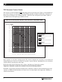
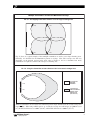
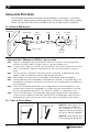
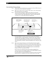
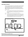
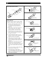
Installation
Guide &
User
Manual
SoundPlus ® WIR TX10 Infrared Transmitter,
Selectable 95 kHz or 250 kHz Carrier
Large Area Infrared Listening System
Modulator-Transmitter
Model WIR TX10
MAN 085H
®
Williams
Sound
Helping People Hear
SOUNDPLUS ® WIR TX10 INFRARED TRANSMITTER,
SELECTABLE 95 KHZ OR 250 KHZ CARRIER
INSTALLATION GUIDE AND USER MANUAL
Contents
Page
SYSTEM OVERVIEW
4
INSTALLATION PROCEDURE
6
TX10 TRANSMITTER COVERAGE PATTERNS
TX10 TRANSMITTER SETUP
TX10 POWER WIRING
AUDIO SOURCE CONNECTION
TESTING THE SYSTEM
CONTROLS AND FEATURES
14
TX10 REAR PANEL
TX10 BOTTOM PANEL
RECEIVER INSTRUCTIONS
17
RECEIVER MANAGEMENT
17
USING MULTIPLE EMITTERS
16
TROUBLESHOOTING
18
WARRANTY
20
SPECIFICATIONS
21
NOTES: TAKING A FEW MINUTES NOW TO READ THESE INSTRUCTIONS WILL SAVE TIME AND ENSURE PROPER
SYSTEM OPERATION.
INFRARED RECEIVER PERFORMANCE CAN BE DEGRADED IF THIS SYSTEM IS USED IN CLOSE PROXIMITY
TO HIGH-EFFICIENCY LIGHTING EQUIPMENT WITH SOLID STATE BALLASTS (I.E. HIGH EFFICIENCY
FLUORESCENT) THAT OPERATE AT FREQUENCIES NEAR 95 KHZ. 250 KHZ OPERATION SHOULD BE USED
WHEN THIS OCCURS.
The TX10 is a CLASS 1 LED PRODUCT
Williams
Sound ®
Helping People Hear
3
SYSTEM OVERVIEW
The Williams Sound WIR TX10 Infrared Transmitter uses invisible infrared (IR) light waves
to broadcast speech or music to wireless infrared receivers.
The TX10 accepts a balanced or unbalanced line level audio input and emits an invisible
infrared 95 kHz or 250 kHz frequency throughout the listening area. Infrared receivers detect
the transmission and convert the light signals back into audio signals.
The system is designed to transmit high quality audio for hearing assistance and language
interpretation applications. Because the system uses infrared light for transmission, it is not
affected by radio equipment and does not interfere with radio equipment. No FCC license is
required. The coverage area for the TX10 will vary depending on the receiver being used.
(see Figures 2 and 4 to demonstrate the receiver coverage area when operating a single TX10
transmitter in single channel mode). Generally, an RX3 receiver will operate up to 10,000 ft2
(930 m2); a RX7/8 receiver will operate up to 6,000 ft2 (560 m2); and a RX4 receiver will
operate up to 4,000 ft2 (370 m2). Larger areas can be covered by connecting additional WIR
TX8 Emitters.
The system must be connected to an existing sound system or mixer. It does not have a direct
microphone input. Infrared systems cannot be used in bright sunlight because of sunlight’s
large amount of interfering infrared light.
4
Williams
Sound ®
Helping People Hear
FIGURE 1A: TYPICAL SYSTEM CONFIGURATIONS
TX10 Transmitter
Baseband LED
(Visible From Below)
Audio Source
Power On LED
(Visible From Below)
Amplifier
3
2
1
Power
4 5 6
7
8
9
3
2
1
10
0
Level
4 5 6
7
8
9
3
2
1
10
0
Level
4 5 6
7
8
9
3
2
1
10
0
Level
4 5 6
Line Level Output
Phones
7
8
9
10
0
Level
Audio
Audio
Limit
Limit
Compress
Compress
Audio Input
Audio LED
(Visible From Below)
Power Supply
120 VAC (US): TFP 010
230 VAC (CE): TFP 027
FIGURE 1B: ADDING A TX8 EMITTER FOR GREATER COVERAGE AREA (SEE PAGE 16)
Audio Source
Amplifier
3
2
1
Power
4 5 6
0
10
Level
7
8
9
3
2
1
4 5 6
0
10
Level
7
8
9
3
2
1
4 5 6
0
10
Level
7
8
9
3
2
1
4 5 6
0
10
Level
7
8
9
Phones
Audio
Audio
Limit
Limit
Compress
Compress
Line Level Output
TX8 Emitter
TX10 Transmitter
Power Supply
120 VAC (US): TFP 010
230 VAC (CE): TFP 027
Baseband In
Baseband
Out
Audio Input
Power Supply
120 VAC (US): TFP 010
230 VAC (CE): TFP 027
Baseband Signal
Williams
Sound ®
Helping People Hear
5
TX10 TRANSMITTER COVERAGE PATTERNS
The coverage area for the TX10 will vary depending on the receiver being used. Figures 2 and 4 demonstrate
the receiver coverage area when operating a single TX10 transmitter in single channel mode. Generally, an
RX3 receiver will operate up to 10,000 ft2 (930 m2); a RX7/8 receiver will operate up to 6,000 ft2 (560 m2);
and a RX4 receiver will operate up to 4,000 ft2 (370 m2).
FIG 2: Receiver Coverage Area with TX8 or TX10 Transmitter in Single Channel Mode
(METERS) (FEET)
27
90
24
80
21
70
18
60
15
50
12
40
9
30
6
20
3
10
0
0
-3
- 10
-6
- 20
-9
- 30
- 12
- 40
- 15
- 50
- 18
- 60
- 21
- 70
- 24
- 80
- 27
- 90
RX3 Receiver
1 Channel
(Approx. 10,000 sq. feet., 930 sq. meters)
RX7/8 Receiver
1 Channel
(Approx. 6,000 sq. feet., 560 sq. meters)
RX4 Receiver
1 Channel
(Approx. 4,000 sq. feet., 370 sq. meters)
0
0
10 20 30 40 50
3
6
9
12
15
60 70 80 90 100 110 120 130 140
18
21
24
27
30
34
37
40
43
These patterns are the direct radiation pattern. The infrared radiation does not drop to zero outside the
illustrated patterns; it decreases. It still may be useable at a greater distance, depending on receiver sensitivity
and the reflective characteristics of the room.
Reflections of the infrared light from walls, ceilings, and floors may change these patterns.
Important: Remember to point the transmitter towards the listening audience!
Remember: opaque objects block infrared light. Thus, transmitters cannot be concealed behind opaque walls,
curtains, etc. Neither should transmitters be used in areas of extreme high or low temperatures, humidity, or
chemical environments.
6
Williams
Sound ®
Helping People Hear
FIG 3a: 3-Dimension Foot Pattern
The TX10 floods the listening audience with
a cone shape light pattern as shown here.
The path of the cone shape light leaves a
pattern on the ground, or "foot print," and
indicates where the strongest receiver
reception will occur.
The actual coverage area will vary depending
on the signal strength of the receiver being
used. Refer to Figures 2 and 4 to determine
how many emitters are required for 100%
coverage of the listening area.
To determine the best location for the transmitter, it helps to think of the IR transmitter as an invisible
floodlight. You’ll want to aim it so the listeners are “flooded” with the infrared light. The transmitter should
also be positioned high enough so it won’t be blocked by people and other physical obstructions. See Figure
3b below. Mount the transmitter at least 2 ft. (.61 m) above the audience. Position the transmitter to face
in a slightly downward angle, 20° - that will increase the “throw” of the infrared beam.
FIG 3b: Vertical Beam Spread
Minimum receiver RANGE when operating with a TX8 or TX10 transmitter in Single Channel Mode.
RX3 Receiver: 120' (37 m)
RX7/8: 80' (24 m)
RX4: 70' (21 m)
(Range)
TX10
er Beam
f Transmitt
Center O
30'
SCREEN
6'
STAGE
Williams
Sound ®
Helping People Hear
7
FIG 4: Horizontal and Vertical Radiation Polar Plots
Receiver Coverage Area with a TX8 or TX10 Transmitter in Single Channel Mode
HORIZONTAL RADIATION POLAR PATTERNS
DISTANCE FROM EMITTER TO RECEIVER
120
30
– 90
– 70
– 60
– 50
100
24
80
18
60
12
40
6
20
– 40
– 30
42
140
36
120
30
– 80
– 70
– 60
– 50
100
24
80
18
60
12
40
6
20
– 20
– 10
FEET
36
– 80
METERS
140
FEET
METERS
– 90
42
VERTICAL RADIATION POLAR PATTERNS
DISTANCE FROM EMITTER TO RECEIVER
– 40
– 30
– 20
– 10
0
0
10
10
20
20
30
30
40
40
50
50
60
90
80
60
70
90
80
70
RX3 Receiver
1 Channel
(Approx. 10000 sq. feet., 930 sq. meters)
RX3 Receiver
1 Channel
RX7/8 Receiver
1 Channel
(Approx. 6000 sq. feet., 560 sq. meters)
RX7/8 Receiver
1 Channel
RX4 Receiver
1 Channel
(Approx. 4000 sq. feet., 370 sq. meters)
RX4 Receiver
1 Channel
Reflections of the infrared light from walls, ceilings, and floors may change these patterns.
Important: Remember to point the transmitter towards the listening audience!
If you’re not getting sufficient coverage with a single, properly installed TX10 Transmitter, you’ll need to add
WIR TX8 Emitters to achieve full coverage of your listening area (see page 16, Using Multiple Emitters).
Figures 5a and 5b illustrate how multiple emitters can be used for large room installations.
8
Williams
Sound ®
Helping People Hear
Multiple Transmitters Installed to Maximize Coverage
FIG. 5a: Overlapping Illumination Patterms to Cover Larger Listening Areas
TX10
TX8
TX8
TX8
Fig. 5a above is a typical example of how multiple transmitters are used to cover larger listening areas.
Generally, it is desirable for the illumination patterns to overlap. Note: The coverage area will vary
depending on the infrared receiver being used; refer to Figures 2 and 4 to determine how many
transmitters are required to achieve full coverage of a listening area.
FIG. 5b: Using Two Transmitters at Same Emission Point to Increase Coverage Area
TX10
TX8
Coverage area
with Single
Transmitter
Coverage area
with Second Emitter
Added to Same
Emission Point
(50% increase)
When two transmitters are used at the same emmission point in single channel mode, the overall coverage area
increases 50%. When using an RX3 receiver, as a result, the coverage area will increase to 15,000 ft2 (1,393
m2); the RX7/8 will increase to 9,000 ft2 (836 m2); and the RX4 will increase to 6,000 ft2 (557 m2).
Williams
Sound ®
Helping People Hear
9
INSTALLATION PROCEDURE
The TX10 Infrared Transmitter should not be installed outdoors, or where there is a lot of direct
sunlight indoors. Sunlight generates infrared interference. Certain types of high-efficiency lighting
fixtures can also generate interference at 95 kHz because they use high frequency modulation.
FIG. 6: BRACKET 024 MOUNTING
TX10 Emitter
Swivel Head
Shaft
(optional)
Shaft
Plate
Cover
Mounting
Plate
(To Wall or Ceiling)
tension screw
Mounting
Screws
INSTALLATION STEP 1: MOUNTING THE TX10 TO A WALL OR CEILING
Step 1: Using the mounting plate (Figure 6) as a template, mark the hole locations on the mounting surface
where the TX10 will be installed. See Figure 7 below for optional mounting positions.
Step 2: Locate the top mounting hole in the rear of the TX10 transmitter. Gently screw the male end of the swivel
head on to the transmitter. Tighten the swivel head tension screw: turn clockwise until the connection is
secure.
Step 3: Screw the male end of the shaft into the female end of the swivel head. An additional shaft can be
added to create more distance between the wall/ceiling and Transmitter.
Step 4: Place the plate cover snugly over the mounting plate. This will hide the screws after installation.
Step 5: Screw the male end of the mounting plate into the female end of the shaft. For suspended ceilings, screw
the female end of the shaft into the male end of the T-Bar clip. The mounting bracket is now installed on to
the TX10 Transmitter.
Step 6: Position the TX10 Transmitter and BKT 024 so the mounting plate lines up with the marked holes on the
mounting surface. Fasten the mounting plate to the surface using screws and wall anchors. Mounting
the TX10 to a Suspended Ceiling with Cross Tee: Fasten the T-Bar clip on to the desired Cross Tee.
Step 7: Position the TX10 Transmitter to the desired angle: Begin by gently turning the tension screw (Figure 6)
counter clockwise to release the swivel head. Adjust the TX10 to the desired angle. When the TX10 is in
the desired position, gently turn the tension screw clockwise until the swivel head is securely in place.
FIG. 7: WALL OR CEILING MOUNT
Figure 7a: Mounting the TX10
on to a wall with the BKT 024.
Tip: To keep the TX10 level,
rotate the tension screw (Fig. 6)
so it rests on top of the bracket.
Figure 7b: Mounting the TX10
on to a ceiling with the BKT 024.
10
Williams
Sound ®
Helping People Hear
INSTALLATION STEP 2: TX10 TRANSMITTER POWER WIRING
POWER SUPPLY FOR THE TX10
The TX10 must be supplied power from a Limited Power Source as defined by
EN 60950:1992; Clause 2.11. Units operated from 120 VAC must use Williams Sound part
number TFP 010. Units operating from 230 VAC must use Williams Sound power supply
part number TFP 027/UK.
WARNING: POWERLINE VOLTAGE MUST NOT FALL BELOW 94V, OR
SYSTEM PERFORMANCE WILL BE GREATLY REDUCED!
FOR U.S. APPLICATIONS:
The TX10 Transmitter is supplied with a low-voltage wall transformer power supply
(TFP 010). Two-conductor 18 ga. power cord is included with the transmitter.
FOR APPLICATIONS OUTSIDE THE U.S. REQUIRING 230 VAC MAINS SUPPLY:
Use the transformer power supply, model TFP 027/UK.
Secondary Specifications: 24 VAC, 35 VA, 50/60 Hz.
DO NOT CONNECT THE POWER SUPPLY TO AC POWER YET!!!
Step 1:
Determine the length of power cord needed to reach from the transmitter to the AC
wall outlet where the power supply will be plugged in. If power cord length will
exceed 200 feet (61 m), heavier gauge wire will be required. Use the table below.
Make sure the power supply is not plugged into AC power yet!
Cable Length Required
Up to 10 feet (3 m)
Up to 75 feet (23 m)
Up to 200 feet (61 m)
Up to 500 feet (152 m)
Up to 1,000 feet (305 m)
Minimum Wire Gauge
22 gauge
20 gauge
18 gauge
16 gauge
14 gauge
One end of the power cord has a 3-pin Molex connector, the other end is bare. Cut the
bare end of the power cord to length. Strip this end down the middle approximately 1
inch, then strip both of the resulting strands about 1/8 inch. Install the crimp-on spade
terminals supplied and connect these to the screw terminals on the power supply (TFP
010). Polarity is not important since AC power is being used.
Step 2:
Plug the 3-pin Molex connector into the TX10’s Power In connector.
Step 4:
Plug in the Power Supply last.
The Power Indicator LED on the right side of the bottom panel (visible from
directly underneath) glows when the TX10 is on.
The TX10 transmits when an audio signal is present, and will shut off when no
signal is present for about 30 minutes. This auto shut-off feature preserves the life
of the infrared LEDs and reduces power consumption.
Note:
This system is designed for Class 2, low-voltage wiring. Always follow local electrical codes
when doing low voltage wiring.
Williams
Sound ®
Helping People Hear
11
INSTALLATION STEP 3: AUDIO SOURCE CONNECTION
The WIR TX10 accepts audio signals from balanced or unbalanced line level outputs,
transmitting audio with excellent fidelity. Therefore, be sure to connect its input to the
highest quality audio source your system can offer.
Step 1:
Determine the length of cable needed to reach from the audio source to the TX10
Transmitter. You will need to cut it to length. Make sure you leave some slack at
each end.
Step 2:
Prepare the cable for an unbalanced or balanced connection. (See Figure 8a.)
Step 3:
Connect the audio cable to the Audio Input terminals using Figure 8b as a guide.
FIGURE 8A: CONNECTING THE TX10 TO AN AUDIO SOURCE
In Phase
To TX10
To TX10
Unbalanced Line Using 1/4" Connector
Balanced Line Using 1/4' Connector
In Phase
To TX10
To TX10
1
3 Pin Connector
1
2
2
3
3
3 Pin Connector
Unbalanced Line Using 3–Pin Connector
Balanced Line Using 3–Pin Connector
FIGURE 8B: CONNECTING AN AUDIO SOURCE TO THE TX10
Signal
POS
NEG
GND
+
–
G
POS
Shield
Jumper
Unbalanced
12
+
NEG –
G
GND
Signal
Signal
Shield
Balanced
Williams
Sound ®
Helping People Hear
INSTALLATION STEP 4: TESTING THE SYSTEM
Step 1:
After the power cable and audio source are connected, the Power LED indicator on
the right side of the the bottom panel should light.
Step 2:
Make sure the sound system is on and your audio source is active. Turn the Audio
Input Adjust if necessary. (See Figure 9.)
Step 3:
Look at the TX10's bottom panel. With the input signal present and power
connected, three lights should be visible from directly underneath the panel: the
red Power LED, the amber Audio LED indicator, and the green Baseband LED.
At normal levels, the Audio LED should flash intermittently.
FIGURE 9: WIR TX10 CONTROLS (ACCESSIBLE THROUGH VENT HOLES)
Audio LED [amber]
Flashes to indicate
audio signal
Baseband LED [green]
Indicates presence
of baseband signal
Power LED [red]
Indicates transmitter
is on when lit.
FRONT
BACK
Audio Input Adjust
Controls level of
audio signal
Frequency Switch
Selects between carrier
frequencies
95 kHz 250 kHz
If the Audio LED does not flash at all, increase the audio level by turning the
Audio Input Adjust (accessible through the vent holes) with a small screwdriver or
similar tool. If the Audio LED is lit constantly, decrease the Audio Input Adjust.
The baseband and Baseband Indicator will shut off after the audio signal has been
absent approximately 30 minutes. If the Baseband LED is not on, check your audio
source.
Step 4:
Take a receiver into the listening area and walk around to check the reception.
Make sure the transmitter and receivers are set to the same frequency. Make sure
the “eye” on the receiver is not covered up when in use. The receiver will not work
if it is placed in a pocket or purse; its eye must be able to “see” the transmitter
panel. A WIRM-1 Infrared Field Strength Meter may be used to check signal
strength if the TX-10 is operating on 95 kHz.
It may be necessary to adjust the angle of the transmitter to obtain the best
coverage. If coverage is not adequate, add one or more WIR TX8 Emitter panels to
the system. (See page 16, Using Multiple Emitters)
If the Audio LED is on, the Baseband LED is flashing, but you don’t hear anything
from the receiver, try a different receiver to be sure the receiver is not at fault.
Williams
Sound ®
Helping People Hear
13
CONTROLS AND FEATURES
WIR TX10 REAR PANEL
POWER IN
21 VAC to 26 VAC only, 50 or 60 Hz (120 VAC [US]: TFP 010 Power Supply / 230 VAC
[CE]: TFP 027 Power Supply). Consumption is 35 VA.
AUDIO INPUT
The WIR TX10's input circuit is constructed with a differential amplifier, providing better
performance than that available using a transformer. It is fully protected from RFI/EMI.
Both balanced and unbalanced line level signals can be accommodated. The minimum
acceptable level is approximately 100 mV, and the maximum level before clipping is
approximately 10 V.
25 V, 70 V, and 100 V speaker distribution lines can be connected to the Line input using
attenuator made with resistors or with speaker-matching transformers. Resistor attenuator
yield better results. Design the attenuator to deliver about 1 V of audio to the input of the
TX10.
BASEBAND OUT
A carrier tone of either 95 kHz or 250 kHz is provided at this BNC connector. One 50 Ω
device may be connected here using RG-58 cable. Additional devices may be connected by
FIGURE 10: WIR TX10 REAR PANEL
Williams
Sound ®
Helping People Hear
WIR TX10 Multi-Channel Infrared Transmitter
CAUTION
RISK OF ELECTRIC SHOCK
DO NOT OPEN
WARNING: TO REDUCE THE RISK OF FIRE OR
Class I
ELECTRIC SHOCK DO NOT EXPOSE THIS
Made in U.S.A.
LED Product
EQUIPMENT TO RAIN OR MOISTURE.
Note: It is normal for this unit to feel warm while it is in operation.
Audio Input
Mounting
Template
Line Level, Bal. or Unbal
POS
Power Supply Wiring:
NEG
For up to 200 ft. (61m): Use NEC, Class 2 Wiring, 18 ga.
For lengths greater than 200 ft. (61m), see the manual.
GND
+
–
G
Signal
Signal
Shield
Balanced
Signal
+
–
G
Williams Sound Corp., Minneapolis, Minnesota, USA
Shield
Jumper
Unbalanced
Power In:
24VAC
50-60Hz
35VA
NC
Plug
C
Baseband Out
(Modulation)
24
Baseband LED
Power LED
50 Ohms
Audio Input Adjust
Audio LED
250kHz 95kHz
Power Connection
120 VAC (US): TFP 010
230 VAC (CE): TFP 027
14
BKT 012 Wall/Ceiling
Mount Template
Set of threaded holes for
use with omnidirectional
mount.
Audio Input
Terminal block, accepts
line level, balanced or
unbalanced inputs
Baseband Out
BNC Connector, 50 Ω,
50 kHz–1 MHz Baseband
®®
Williams
Williams
Sound
Sound
Helping
HelpingPeople
PeopleHear
Hear
“looping through” the connected device or by means of a suitable distribution amplifier. The
output impedance is 50 Ω. Frequency accuracy is better than ± .010%. Deviation is ± 50 kHz,
maximum.
WIR TX10 BOTTOM PANEL
POWER LED
Indicates actual operation of the transmitter. Does not indicate status of power supply.
FREQUENCY SWITCH
This slide switch selects between carrier frequencies of 95 kHz and 250 kHz. Accessed
through holes in chassis bottom.
AUDIO INPUT ADJUST
Controls level of audio signal. The control is connected between the input amplifier and the
audio level processing circuit. Accessed through holes in chassis bottom.
AUDIO LED
Flashes to indicate audio signal level. When Audio Input Adjust is set correctly and volume
is normal, the LED should flash intermittently.
BASEBAND LED
Lights when audio signal is present.
FIGURE 11: WIR TX10 BOTTOM PANEL
Audio LED
Flashes to
indicate
audio signal
Baseband LED
Indicates presence
of baseband signal
Power LED
Indicates
transmitter is
on when lit.
FRONT
BACK
Audio Input Adjust
Controls level of
audio signal
Frequency Switch
Selects between carrier
frequencies
95 kHz 250 kHz
Williams
Sound ®
Helping People Hear
15
USING MULTIPLE EMITTERS
Listening areas of more than 10,000 square feet (930 square meters) will require a TX10 and
at least one TX8 Emitter for complete coverage. Place one TX10 transmitter on the left side
of the front wall and one TX8 emitter on the right hand side. For extremely large venue,
additional TX8s should be located to maximize coverage throughout the listening area.
Figures 5a and 5b illustrate infrared light patterns and recommended emitter locations. A
WIRM-1 Infrared Field Strength Meter may be used to check signal strength if the TX-10 is
operating on 95 kHz.
Step 1:
Determine the length of coaxial cable needed to reach between the emitters. 100
feet (30 m) of coaxial cable is included with each emitter. You will need to cut it to
length. Additional RG–58 coax can be added. Make sure you leave some slack at
each end.
Step 2:
Install BNC connectors on each end of the cable. (See Figure 13.)
Step 3:
Connect the baseband cable from the Baseband Out jack on the TX10 Transmitter
to the Baseband In jack on the first TX8 emitter in the chain. Use the cable clamps
and screws provided to secure the cable. The coax can also be routed through
conduit before attaching BNC connectors. You can chain as many emitters together
as you need. Remember that each emitter needs its own power supply.
FIGURE 12: WIRING DETAIL, MULTIPLE EMITTERS
Audio Source
Amplifier
Phones
Power
Level
Level
Level
Level
Audio
Audio
Compress
Compress
Line Level Output
TX10 Transmitter
TX8 Emitter
Baseband In
Baseband Out
Audio In
To Additional
TX8 Transmitters
Baseband Out
Power Supply
120 VAC (US): TFP 010
230 VAC (CE): TFP 027
Power Supply
120 VAC (US): TFP 010
230 VAC (CE): TFP 027
RECEIVER INSTRUCTIONS (OPTIONAL)
16
Williams
Sound ®
Helping People Hear
IR RECEIVER MODELS WIR RX3, WIR RX7, WIR RX8
Make sure the “eye” on the front of the receiver is not covered up when in use. The receiver is intended to be
worn on the front of the body, hanging from the lanyard attached to the receiver. The receiver will not work if
it is placed in a pocket or purse. A variety of earphones, headphones, or neckloop telecoil couplers can be
used with RX3, RX7 and RX8 Receivers.
Step 1:
To install batteries in the RX7, or RX8, open the battery compartment using a coin in
the slot in the bottom of the receiver. Press two AA batteries into place, observing proper
battery polarity.
Step 2:
Plug the earphone or headphone into the earphone jack.
Step 3:
Turn the receiver on by rotating the volume control knob clockwise.
Step 4:
Adjust the tone to your preference using the slide switch tone control. (Not on the RX3 or
RX4) To avoid draining the battery, make sure the receiver is turned off when not in use.
BATTERY INFORMATION
For RX7, or RX8 Receivers in normal use, two AA alkaline batteries (BAT 001) will last about 30 hours.
Rechargeable AA batteries (BAT 026) will last about 15 hours per charge. (The RX3 uses a 9V battery.)
If you are using BAT 026 rechargeable batteries, use the CHG 200A Multi-Charger. Contact your dealer or
Williams Sound for details.
If the sound becomes weak or distorted, replace the batteries. The indicator light may still be on, even with
weak batteries. Do not leave dead batteries in the receiver, they may leak and damage the receiver.
RECEIVER MANAGEMENT
Different types of facilities will use different approaches for receiver management and earphone sanitation. Below
are some options that customers have used successfully.
Regular users purchase their own receiver and take care of their own batteries and earphone.
Some facilities label the receiver and earphone with the names of regular users so each person uses the same receiver
and earphone.
Ushers issue receivers to people who request them. Earphones are sanitized after use. Foam ear cushions can be
replaced or washed with a mild detergent, rinsed thoroughly and air-dried. The EAR 022 Surround Earphone can be
sanitized with an alcohol pad.
The receivers can be stored in a multiple compartment storage case with a credit card or
driver's license left as collateral for the receiver.
!! IMPORTANT WARNINGS !!
DO NOT ATTEMPT TO RECHARGE ZINC CARBON (“HEAVY DUTY”), ALKALINE, OR LITHIUM
BATTERIES!
DO NOT ATTEMPT TO RECHARGE DISPOSABLE BATTERIES! These batteries may heat up and
explode, causing possible injury and damage to the equipment.
Avoid shorting the plus and minus battery terminals together with metal objects. Battery damage
and burns can result!
Use only Williams Sound supplied charger and batteries!
Williams
Sound ®
Helping People Hear
17
Regular users purchase their own earphone or headphone and bring them to use with
receivers at the facility.
Some facilities use the drop-in style CHG 200 or CHG 1269 Multi-charger for both
storing and charging receivers
TROUBLESHOOTING
NO INDICATOR LIGHTS ARE ON (FIG 9).
Make sure the wall transformer is plugged into the transmitter and the power switch or
any remote power switch is on.
Make sure the electrical outlet is on.
Make sure the 24 VAC power supply is working.
ONLY ONE INDICATOR LED (RIGHT) COMES ON (FIG 9).
Make sure an audio signal is being sent to the WIR TX10.
NO SOUND THROUGH RECEIVERS.
If some of the receivers work but others don’t, check for bad batteries or earphones on
the receivers that aren’t working.
If none of the receivers work, check to see if the power and audio are connected to the
transmitter and that the Power and Audio LEDs are ON.
Check to see if the TX10 is connected properly to the sound system. The Audio LED
should flash intermittently. If it does not light, turn the Audio Level Adjust with a small
screwdriver or similar tool. The Audio Level Adjust is accessible through the TX10's
bottom panel vent holes.
Make sure the “eye” is not covered up on the receiver. There must be clear line of sight
between the receiver eye and the transmitter panel.
Make sure the selected modulator frequency matches the selected receiver frequency.
SOUND THROUGH THE RECEIVERS IS WEAK AND NOISY.
Try increasing the input signal level from the sound system by turning up a mixer
control. If this does not help, you need to re-position the transmitter panels or add
additional panels.
NOTE: Make sure the powerline voltage does not fall below 94V or system
performance will be greatly reduced!
BUZZING OR HUMMING NOISE IN SOUND SYSTEM.
18
Check for ground loops or noise on the input signal. Call your Authorized Dealer or
Williams Sound for help.
Williams
Sound ®
Helping People Hear
13B
FIGURE 13: BNC CONNECTOR ASSEMBLY
Washer
7.92 mm (± .25)
.312 in. (± .01)
Grooved Side
Nut
Gasket (note groove)
Nut
Cable Jacket
Washer
Plug
Assembly
Gasket
13C
Clamp
Contact
Clamp positioned
against Cable Jacket
ASSEMBLY PROCEDURE
13D
The BNC Connector consists of a plug assembly,
a contact, a clamp, a gasket, a washer, and a nut.
1. Slide nut, washer and gasket over cable end;
then strip outer cable jacket using the
recommended strip-length dimension in
figure 13b.
Clamp Collar
Clamp Braid folded
over Clamp and trimmed
13E
2. Slide clamp over cable braid and position it
against the cable jacket. After clamp is
properly positioned, comb out the braid.
3. Fold cable braid over the clamp and trim it so
that it is positioned against the clamp collar.
See figures 13c and 13d.
3.96 mm (± .25)
.156 in. (± .01)
Dielectric
13F
4. Using the dimension in figure 13e, strip
dielectric to expose the center conductor. If
applicable, tin the center conductor.
5. Solder contact to the conductor (using
standard soldering techniques), making sure
contact is bottomed on cable dielectric. See
figure 13f.
Dielectric
Contact soldered to conductor
and bottomed on dielectric
13G
Gasket (Ref.)
DO NOT allow a hot soldering iron to touch
cable dielectric. Certain cable dielectric
materials, such as polypropylene, will expand
if they come in contact with a hot soldering
iron.
6. Insert contact into plug assemble until contact
snaps into place. See figure 13g.
7. Thread nut into plug assembly until it is
secured. Recommended cable clamp tightening
torque is 2.8–3.4 N•m [25-30 in.-lb.], using a
7/16" wrench. See figure13h.
Williams
Sound ®
Helping People Hear
Contact Assembly
inserted into Plug
Assembly
Plug Assembly
13H
50 Ω BNC Plug Connector
Nut Secured Into
Plug Assembly
19
Warranty
The Williams Sound WIR TX10 Infrared Transmitter is engineered and designed to provide you with
many years of reliable service. Williams Sound warrants against defects in materials and
workmanship for FIVE (5) years EXCEPT FOR earphones, headphones, rechargeable batteries,
charger, cables, antennas, carry cases, and all other accessory products. Accessory products carry
a 90 day warranty.
If the product fails within the specified warranty period, Williams Sound will determine whether to
repair or replace the defective equipment. This warranty does not apply to physical damage,
abuse, mis-use, or products that have been modified. This warranty does not apply to damage
caused by attempting to charge non-rechargeable batteries.
If you experience difficulty with your system, call for Customer Assistance:
1-800-328-6190.
If it is necessary to return the system for service, a Williams Sound representative will give you a
Return Authorization Number (RA) and shipping instructions.
Pack the system carefully and send it to:
Williams Sound Corp.
10321 West 70th Street
Eden Prairie, MN 55344-3459 USA
Phone: 800-843-3544
952-943-2252
Fax:
952-943-2174
TTY:
952-943-9675
e-mail: [email protected]
Canadian Customers
Please contact:
European Customers
Please contact:
Thorvin Electronics
2861 Sherwood Hgts Dr
Units 36-37
Oakville, ON L6J-7K1 Canada
Phone: 905-829-3040
Phone: 800-323-6634
Fax: 905-829-4196
email: [email protected]
Doreen Armstrong
Urb. Los Naranjos de Marbella
Fase 2 Apartamento 7
29660 Nueva Andalucia, Marbella SPAIN
Phone: (34) 952 819 069
Fax: (34) 952 819 201
email: [email protected]
Your warranty becomes effective the date you purchase your system. Your returned warranty card
is our way of knowing when your warranty begins. It also gives us important information about your
system including the serial number. This information will help us serve you better in the future. Please
take a moment to complete and mail the attached card. Thank you.
20
Williams
Sound ®
Helping People Hear
SoundPlus® WIR TX10 Infrared Transmitter Specifications
INFRARED TRANSMITTER, MODEL TX10
Dimensions, Weight:
11.25" W x 6.25" H x 2.125" D (28.6 cm x 15.9 cm x 5.4 cm) 1.9 lbs. (0.9 kg)
Color:
Black anodize with white legends, red acrylic window
Wall Mount:
BKT 024 mounting bracket included for wall and ceiling mounting.
Tripod Mount:
Optional SS-6 Tripod Stand Kit available
Operating Req.:
0-50° C (32-106° F) ambient temperature, non-condensing, non-corrosive atmosphere
Frequency:
95 kHz or 250 kHz; ± 50 kHz deviation, 50 µsec pre-emphasis
Power Requirements:
24 VAC; 50-60 Hz; Supplied by TFP 010 (120 VAC) or TFP 027/UK (230 VAC Input)
Signal to Noise Ratio:
55 dB
Audio Frequency Response:
50 – 15,000 Hz, +1, –3 dB
Coverage Area:
RX3 Receiver: 10,000 ft2 (930 m2); RX7/8 Receiver: 6,000 ft2 (560 m2); RX4 Receiver: 4,000 ft2 (370m2)
50° cone pattern; For larger areas, connect add’l WIR TX8 Emitters
Carrier Timer:
One 30 minute (approx.) timer. Turns off TX10 if audio signal is absent for 30 minutes
Infrared LEDs:
120
Infrared Type:
Class 1 LED Product
REAR PANEL:
Mounting Holes:
Line Level Input:
One set of threaded holes for use with the BKT 024 mounting bracket (included); Two
threaded holes on sides of the cabinet for Tripod Stand Kit
Terminal block, accepts unbalanced or balanced line level inputs
Baseband Output:
BNC connector, 50 Ω
Baseband Cable:
RG-58 Coax, BNC-connectors
Power:
External power supply, 3-pin molex connector, 24 VAC, 50 or 60 Hz, 35 VA, 0.9 A nom.
current drain
Power Cable:
NEC Class 2 wiring, 2-conductor, 18 ga.; 200 foot (61 m) max. length for 18 gauge wire
(See table below for minimum gauge requirements at other lengths)
Each TX10 Transmitter requires its own 24 VAC Power Supply
Cable Length Required
Up to
10 feet (3 m)
Up to
75 feet (23 m)
Up to
200 feet (61 m)
Up to
500 feet (152 m)
Up to
1,000 feet (305 m)
Minimum Wire Gauge
22 gauge
20 gauge
18 gauge
16 gauge
14 gauge
BOTTOM PANEL:
Power LED:
Red LED, visible from bottom through vent holes, right side
Baseband LED:
Green LED, visible from bottom through vent holes, center
Audio LED:
Amber LED, visible from bottom through vent holes, left side
Frequency Selector Switch:
Slide-type, selects between 95 kHz or 250 kHz
Audio Input Adjust:
Controls audio input level, screwdriver-adjust
Warranty:
Five Years, Parts and Labor.
90 days on cords, earphones, headphones, batteries and other accessories
NOTE:
SPECIFICATIONS SUBJECT TO CHANGE WITHOUT NOTICE.
Infrared receiver performance can be degraded if this system is used in close proximity to highefficiency lighting equipment with solid state ballasts (i.e. high efficiency fluorescent) that operate
at frequencies with harmonics near 95 kHz. 250 kHz operation should be used when this occurs.
POWER SUPPLY FOR THE TX10
The TX10 must be supplied power from a Limited Power Source as defined by EN 60950:1992; Clause
2.11. Units operated from 120 VAC must use Williams Sound part number TFP 010. Units operating from
230 VAC must use Williams Sound systems part number TFP 027/UK.
Williams
Sound ®
Helping People Hear
21
INFRARED RECEIVERS, MODELS WIR RX7 & WIR RX8 (OPTIONAL)
Size and Weight:
Color and Material:
Battery Type:
Battery Life:
Modulation Frequency:
Signal to Noise Ratio:
Controls:
Audio Output:
Acoustic Output:
3-5/8" L x 2-3/8" W x 7/8" H (9.2 cm x 6 cm x 2.4 cm) 4.48 oz. (127 g)
Grey, shatter-proof polypropylene
1.5V (AA) x 2, Alkaline (BAT 001) or Rechargeable AA NiMH (BAT 026)
30 hours with BAT 001, 15 hours/charge with BAT 026, 25 mA, nom.
current drain
RX7: 250 kHz FM, 50 µS de-emphasis; RX8: 95 kHz FM, 50 µS de-emphasis
60 dB
Combination volume/On-Off knob,
Switched Low-Cut tone control (Lo: 20 Hz / Mid: 120 Hz / Hi: 700 Hz)
3.5 mm mono mini phone jack, 35 mW maximum into 16 Ω
130 dB MAX SSPL90 with EAR 013
Note:
The RX7/RX8 Infrared Receivers can be used with a Neckloop TeleCoil
Coupler (NKL 001) to magnetically couple into a hearing aid that has a
telephone pick-up coil.
Add’l Compatible Receivers: WIR RX3: Single Channel Infrared Receiver, operates at 95 kHz
WIR RX4: Single Channel Infrared Receiver, operates at 95 kHz
Warranty:
Five Years, Parts and Labor.
90 days on cords, earphones, headphones, batteries and other accessories
NOTE:
SPECIFICATIONS SUBJECT TO CHANGE WITHOUT NOTICE.
Infrared receiver performance can be degraded if this system is used in close
proximity to high-efficiency lighting equipment with solid state ballasts (i.e. high
efficiency fluorescent) that operate at frequencies with harmonics near 95 kHz.
250 kHz operation should be used when this occurs.
22
Williams
Sound ®
Helping People Hear
RECYCLING INSTRUCTIONS
BATTERY SAFETY AND DISPOSAL
Help Williams Sound protect the environment! Please take the time to dispose of your
equipment properly.
Product Recycling for Customers in the European Union:
Please do NOT dispose of your Williams Sound equipment in the household trash. Please take
the equipment to a electronics recycling center; OR return the product to the factory for
proper disposal.
Battery Recycling for Customers in the European Union:
Please do NOT dispose of used batteries in the household trash. Please take the batteries to a
retail or community collection point for recycling.
12/07/05
Williams
Sound ®
Helping People Hear
23
Williams Sound Corp.
10321 West 70th St., Eden Prairie, MN 55344-3459
U.S.A. 800-328-6190 / 952-943-2252 / FAX: 952-943-2174
24
www.williamssound.com
© 2005, Williams Sound Corp.
MAN 085H