1
CE
INSTALLATION and
OPERATING INSTRUCTIONS
Water-Water Heat Pump
for indoor installation
WI 40CG
Order No.: 452225.66.94
WI 90CG
FD 8209
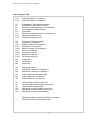
CONTENTS
1
PLEASE READ IMMEDIATELY
3
1.1
1.2
1.3
Important notes
Legal requirements and guidelines
Energy-saving heat pump operation
2
APPLICABILITY OF THE
HEAT PUMP
2.1
2.2
Field of application
Mode of operation
3
BASIC UNIT
4
4
ACCESSORIES
5
4.1
4.2
Control cable
Heat pump control
5
TRANSPORT
5
6
INSTALLATION SITE
6
6.1
6.2
General notes
Sound emission
7
INSTALLATION
7.1
7.2
7.3
Connection of the heating system
Connection of the heat source
Connection to power supply
8
STARTUP
8.1
8.2
General notes
Preparation
9
MAINTENANCE/CLEANING
9.1
9.2
9.3
Maintenance
Cleaning the heating side
Cleaning the heat source side
10
MALFUNCTIONS/
TROUBLE SHOOTING
10.1
Eliminating minor faults
11
SHUTDOWN
11.1
11.2
Shutdown during summer
Final discommissioning/disposal
12
ANNEX
4
6
8
9
10
10
11
2
PLEASE READ IMMEDIATELY
1
PLEASE READ IMMEDIATELY
CAUTION !
After cleaning it is essential to neutralize the system by suitable means in order to
prevent secondary damages to the heating
system.
1.1 Important notes
CAUTION !
During transport the heat pump must
not be inclined to any side by more than 45°.
CAUTION !
The heat pump is not intended to meet
the increased heat requirements of de-humidifying a building. Therefore it is necessary to use
dedicated equipment provided by the client to
generate the extra amount of heat needed for that
purpose.
CAUTION !
The heat pump is not attached to the
wooden grating.
1.2 Legal requirements and guidelines
CAUTION !
Disconnect all voltage supplies prior
to opening the unit.
The heat pump complies with all relevant DIN/
VDE regulations and EEC directives. These are
listed in the attached CE conformity statement.
CAUTION !
Electric wiring of the heat pump must comply with
the applicable VDE, EN and IEC standards.
Furthermore, the electrical supply conditions
stipulated by the power provider must be
observed.
Service of the heat pump must be
performed by authorized and experienced
service personnel only.
CAUTION !
The working fluid R407C is free of CFC,
does not disturb ozone and is non-combustible.
The heat pump must be interconnected with the
heat source and the heating system in compliance with the relevant regulations.
CAUTION !
Service of the heat pump must be
performed by authorized and experienced
service personnel only.
CAUTION !
Ensure the clockwise rotating field
when connecting the supply cable.
CAUTION !
1.3 Energy-saving heat pump operation
The covering hood can not be painted.
By operating this heat pump you contribute to the
protection of our environment. Proper dimensioning of the heating system and the heat source
are of prime importance for the efficiency of heat
pump operation. Low water inlet temperatures
are of particular importance. Therefore, all connected heat consumers must be suitable for low
water inlet temperatures. An increase in the
heating water temperature by 1 K causes an
increase in the electrical power consumption by
approx. 2.5%. An underfloor heating system with
forward temperatures between 30 and 40 °C is
particularly well suited for energy-saving operation.
CAUTION !
The well water must be of the water
quality specified.
CAUTION !
The startup procedure must follow the
Installation and Operanting Instructions for the
heat pump control.
3
APPLICABILITY OF THE HEAT PUMP
BASIC UNIT
2
APPLICABILITY OF THE
HEAT PUMP
3
2.1 Field of application
The water-water heat pump can be used in
existing or new heating plant installations. Water
is used as the heat transfer medium. The water
may be supplied from a well or similar sources.
BASIC UNIT
The basic unit consists of the heat pump for
indoor installation, covering hood and basic
control and is delivered ready for installation. The
refrigerating circuit is filled with the refrigerant
R407C. The covering hood is lined with sound
insulating material.
The basic control contains all components that
are required for heat pump operation. The power
cable and the load cable (accessories) between
heat pump and basic control have to be installed
by the client.
CAUTION !
The well water must be of the water
quality specified.
The well pump, that is also provided by the client,
has to be interfaced with the basic control. Make
sure that the rating of the motor protector istalled
by the client is sufficient for the pump in use.
Under normal conditions an intermediate circuit
has to be provided. If the system is to operated
without an intermediate circuit it is, independent
of the leagl requirements, necessary to perform
a water analysis in order to be able to detzermine
the compatability of the ground water with the
evaporator of the heat pump (refer to the project
designing and installation manual for heating
heat pumps).
1
2
6
7
3
4
5
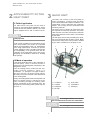
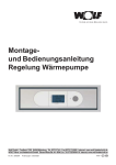
2.2 Mode of operation
A well pump feeds the water to the evaporator of
the heat pump. There its thermal content is
transferred to the working fluid (refrigerant) in the
refrigeration circuit.
Then the working fluid is sucked into the electrically powered condensor, where it is
condensed , i.e. "pumped" to a higher temperature level. How-ever, the electric energy used to
drive this process is not lost but is also transferred
to the working fluid.
Finally, the working fluid reaches the liquefier unit
where its thermal energy is transferred to the
water circulating through the heating water
system. Depending on the operating point, the
temperature in the heating water system may rise
up to 55 °C.
1)
2)
3)
4)
Condensor
Liquefier
Evaporator
Dirt trap
5) Flow switch
6) Terminalbox
7) Filter dryer
CAUTION !
The working fluid R407C is free of CFC,
does not disturb ozone and is non-combustible.
CAUTION !
4
The covering hood can not be painted.
ACCESSORIES
TRANSPORT
4
ACCESSORIES
4.1 Control cable
5
Two control cables serve to interconnect the heat
pump control and the basic control unit as well
as the basic control unit and the terminal box of
the heat pump. These cables are available in
several lengths.
4.2 Heat pump control
The use of a heat pump control from our product
line is mandatory for the operation of your waterwater heat pump. The heat pump control is a
comfortable electronic control device. It is available as an accessory. The heat pump control
regulates and monitors the entire heating system
in regard to outdoor temperatures, hot water
heating process and safety-relevant equipment.
The functional method and the operation of the
heat pump control is described in detail in the
accompanying Installation and Operating Instructions.
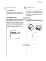
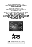
TRANSPORT
A lift truck can be used for transporting the heat
pump over smooth surfaces. Carrier belts should
be used where it must be transported across
uneven surfaces or through staircases. The belts
can be inserted directly through the wooden grate.
As an alternative the unit may be lifted by means
of eyebolts that can be screwed into the corners
of the base frame.
CAUTION !
The heat pump is not attached to the
wooden grate.
45°
45°
Eye bolt
CAUTION !
The heat pump must not be inclined
by more than 45° (to any side).
5
INSTALLATION SITE
INSTALLATION
6
INSTALLATION SITE
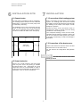
6.1 General notes
7
The heat pump is intended for indoor installation.
The mounting surface must be smooth, solid and
load-bearing. If necessary, the heat pump must
be levelled by shimming.
INSTALLATION
7.1 Connection of the heating system
Before connecting the heat pump to the heating
system, the heating plant should be flushed
thoroughly to prevent any particles to flow through
the heating circuit which could impair smooth
heatpump operation.
The installation site of the heat pump must be
chosen so that service work can be performed
easily. This is ensured by a free space of about 1
m at the front and both sides of the heat pump.
Flexible pressure hoses should be used for
connections in order to prevent noise from being
conducted to the heating circuit.
The completed heating circuit must be filled,
ventilated and checked for leakage. Where the
risk of frost exists the filled system must remain
in operation continuously so that frost damage is
precluded.
0,2 m
7.2 Connection of the heat source
1m
Wärmepumpe
Heat
pump
1m
Connect the water lines from the well to the flow
and return lines of the heat source.
For this observe the refrigeration and hydraulic
plans.
1m
CAUTION !
The well water must be of the water
quality specified.
6.2 Sound emission
Owing to the sound insulation the heat pump
emits very little noise. But placing a suitable
decoupled rubber mat underneath the heat
pump base frame is recommended in order to
prevent any sound conductance to the foundation,
especially in case of uneven foundations.
6
INSTALLATION
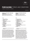
7.3 Connection to power supply
%DVLFFRQWUROXQLW
It must be ensured that the the power supply to
the terminals of the well pump will not be turned
off by the tariff contactor to make sure that the
cutoff delay of the well pump remains effective.The motor protector installed by the client
must be adjusted according to the data
specified by the pump manufacturer. The
terminals for the power supply to the well pump
are X1-L11/L21/L31.
+HDWSXPSFRQWURO
/RDGRIKHDWSXPS
3(9$&
/RDGRIZHOOSXPS
$FFHVVRU\FRQWUROFDEOH
3(9$&
5)
/13(9$&
H
O
E
&RQWUROFXUUHQW
D
F
O
R
U
W
Q
R
F
\
U
R
V
V
H
F
F
$
U
R
V
Q
H
G
Q
R
&
3HULSKHUDO
KHDWSXPSFRQWURO
3HULSKHUDO
KHDWSXPSDXWRFRQWURO
3
:6
:6
7!
7!
+': +'% +'6% (*6
3
3
3
Connection between the basic control unit and
the terminal box of the heat pump
The connection between the terminal box of the
heat pump and the basic control unit as well as
between the brine pump and the basic control
unit must be provided by the client.
+]J
+]J
1'
Control voltage
The basic control unit is powered by the heat
pump control via the control cable. A separate
cable to the basic control unit is not required.
$)
7
')6
)
:HOOSXPS
Select the cable cross section according to the
power consumption of the heat pump (see
technical specifications) and the power consumption of the used brine circulating pump.
All components needed for connecting the
electric supply to the heat pump are located in
the basic control unit. Mount this unit to a
smooth wall surface of the building. A heat
pump control is necessary for controlling these
components. The wiring of the descrete components contained in the basic control unit and in
the heat pump control must be provided by the
client (plug connectors).
Run the power cables in the existing plastic
tubing.
Terminals of the condenser:
X1-1/2/3/PE
X1-4/5/6/PE
Power supply for the basic control unit
A breaker controlling all poles with at least 3
mm contact gap (e.g. EVU blocking contactor,
power contactor) and a three pole automatic
circuit breaker separating simultaneously all
external leads must be provided in the power
feed to the basic control unit. Select the wiring
cross section according to the power consumption of the heat pump, the technical power
connecting requirements stipulated by the
respective power provider and the requirements of VDE 0100. The power consumption of
the heat pump is specified in the technical
documentation. The terminals (X1-L1/L2/L3 at
the circuit breaker) are rated for a maximum wire
gauge of 16 mm².
Terminals of the well pump:
X1-7/8/9/PE
7
INSTALLATION
STARTUP
Control cable between the basic control unit
and the terminal box of the heat pump
The control cable between the terminal box of
the heat pump and the basic control unit is
available as a custom-made cable (see price
list). Connect the round 16-pole connector of the
control cable to the basic control unit. Slightly
rotate the connector ccw and cw to feel for the
anti-rotation lock. Then insert the connector until
the ring nut of the contactor catches. Turn the
ring nut clockwise to secure the connector in its
position. Feed both the rectangular connec-tors
through the opening in the bottom right corner of
the basic control unit and plug them into the
matching connectors (non-interchange-able).
Use the strain relief to secure the control cable
in the basic control unit . Any excessive cable
length should be kept in the cable duct or as a
loop on the wall.
8
8.1 General notes
For reasons of warranty, comissioning of the heat
pump should be performed by authorized service
personnel.
8.2 Preparation
Confirm the following prior to startup:
Connection between the heat pump control and
the basic control unit (using the 1.5 m control
cable, see price list)
The power for the heat pump control can be
provided from the basic control unit. Plug the
round connector of the cable into the basic control
unit and connect the two rectangular connectors
to the heat pump control. A more detailed
description is contained in the instal-lation and
operating instructions for the heat pump control.
STARTUP
-
The heat source system and the heating water
circuit must have been filled and tested.
-
The shut-off valves in the well and heating
circuits must be in the correct position.
-
The power supply field must rotate in the cw
direction.
-
The heat pump control must have been
prepared according to the relevant installation
and operating instructions.
CAUTION !
The startup procedure must follow the
installation and operating instructions for the heat
pump control.
CAUTION !
Ensure the clockwise rotating field
when connecting the supply cable. (If the field
rotates ccw the heat pump generates no power
and is very loud.)
8
MAINTENANCE/CLEANING
9
MAINTENANCE/
CLEANING
CAUTION !
After cleaning it is essential to neutralize the system by suitable means in order to
prevent secondary damages to the heating
system.
9.1 Maintenance
The heat pump operates maintenance-free.
Make sure that the heat source and heating
circuits are kept free from impurities to prevent
malfunction of the heat pump due to dirt
collections in the heat exchangers. Should a
malfunction of that type occur, clean the unit as
described below.
CAUTION !
Attention - heating plant installers Depending on the fill water quality and volume
occasional dirt collection (rust sludge, calcerous
deposits) may occur especially in case of mixed
installations and plastic piping so that the
performance of the heating system may be
compromized. This is due to the water hardness
and the oxygen solved in the fill water and the
oxygen in the air that may enter the system at
valves, fittings and plastic pipes (oxygen diffusion). To prevent this from happening we
recommend the use of a physical water treatment
device like e.g. ELYSATOR .
CAUTION !
Disconnect all voltage supplies prior
to opening the unit.
9.2 Cleaning the heating side
9.3 Cleaning the heat source side
Oxygen may cause the formation of oxydation
products (rust) in the hot water circuit. Pipe
connections must not allow oxygen diffusion
which applies particularly to pipes used in
underfloor heating. Remnants of lubricants and
sealants may also contaminate the heating
water.
Install the enclosed dirt trap in the heat source
inlet of the heat pump in order to protect the
evaporator from impurities. After the initial startup
the filter screen of the dirt trap should be cleaned
regularly in relatively short intervalst. As soon as
detectable impurities become less the intervalls
can be extended accordingly.
If contamination is so bad that the performance
of the liquefier in the heat pump is degraded,
the installation must be cleaned by a specialist.
Based on today's experience we suggest to use
5% phosphorous acid for general cleaning or, if
cleaning is required in shorter intervals, 5%
formic acid .
In both cases the cleaning liquid should be used
at room temperature. Scavenging the heat exchanger in the direction opposite to the normal
flow is recommendable.
In order to prevent acid-containing cleaning liquid from entering the heating water circuit we
suggest to connect the scavenging unit directly
to the forward and return lines of the liquefier in
the heat pump.
Following that it is essential to thoroughly rinse
the system with a suitable neutralizing agent
so that all remnants of the cleaning agent are
removed from the system.
Handle acids with care. Always follow the
instructions of the occupational associations.
In case of doubt consult with the manufacturer
of the cleaning agent!
9
MALFUNCTIONS/TROUBLE SHOOTING
SHUTDOWN
10
MALFUNCTIONS/
TROUBLE SHOOTING
10.1 Eliminating minor faults
11
SHUTDOWN
11.1 Shutdown during summer
Heat pumps used exclusively for heating purposes can be shut down for the summer time
(no hot water service). This is done by means of
the operating mode selector of the heat pump
control. Please observe the Installation and
Operating Instructions.
This heat pump is a maintenance-free highquality product and should run without any
problems. Most faults that may occur can be
remedied by the user. Please refer to chapter
'Malfunctions and Troubleshooting' in the
installation and operating instructions for the heat
pump control.
Due to the risk of frost damages, shutdown
without draining the heating circuit is permissible
only in regions where outdoor temperatures do
not drop below 0 °C .
If you are not successful in eliminating a fault
please contact your customer service.
CAUTION !
11.2 Final decommissioning/disposal
Service of the heat pump must be
performed by authorized and experienced
service personnel only.
Before removing the heat pump it is necessary to
disconnect all cables as well as the connections
to the heat source and the heating system.
Furthermore, all electrical supplies must be
switched off and all valves must be closed.
Please observe the applicable environmental
regulations in regard to recycling, reuse and
disposal of working materials and fluids according to DIN EN 378, when taking the heat pump
out of operation. Especially the disposal of
refrigerants and refrigeration machine oil must
comply with the relevant regulations.
10
ANNEX
12
ANNEXE
12.1
Dimensional drawings
12.1.1 Heat pump ..40C
12.1.2 Heat pump ..90C
12
13
12.2
Equipment data
14
12.3
Performance characteristics/
pressure losses
Characteristics ..40C / 2 cond.
Characteristics ..40C / 1 cond.
Pressure losses ..40C
Characteristics ..90C / 2 cond.
Characteristics ..90C / 1 cond.
Pressure losses ..90C
15
16
17
18
19
20
12.3.1
12.3.2
12.3.3
12.3.4
12.3.5
12.3.6
12.4
12.4.1
12.4.2
12.4.3
12.4.4
12.4.10
Circuit diagrams
External basic control unit ..40C
Load ..40C
Internal terminal box ..40C
Terminal assignment incl.
heat pump control ..40C
Legend ..40C
External basic control unit ..90C
Load ..90C
Internal terminal box ..90C
Terminal assignment incl.
heat pump control ..90C
Legend ..90C
12.5
Hydraulic schematic diagram 31
12.6
CE conformity statement
32
12.7
Warranty certificate
33
12.4.5
12.4.6
12.4.7
12.4.8
12.4.9
11
21
22
23
24
25
26
27
28
29
30
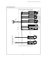
Heat source inlet
Heat source outlet
Heating water outlet
12
External thread
External thread
Connections on heating side:
Connections on heat source side:
Inlet of control cable/load cable
Heating water inlet
Turning lock
ANNEX: 12.1 DIMENSIONAL DRAWINGS
12.1.1 Heat pump ..40C
Heat source outlet
Inlet of control cable/load cable
Heat source inlet
Turning lock
Connections on heat source side 2" External thread
Heating water outlet
Heating water inlet
ANNEX: 12.1 DIMENSIONAL DRAWINGS
12.1.2 Heat pump ..90C
13
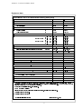
ANNEX: 12.2 EQUIPMENT DATA
Equipment data
(48,30(17'$7$IRUZDWHUZDWHUKHDWLQJKHDWSXPS
7<3($1'0$5.(7,1*'(6,*1$7,21
02'(/
&
&
7\SHRISURWHFWLRQDFFRUGLQJWR(1
,3
,3
6LWHRILQVWDOODWLRQ
LQGRRUV
LQGRRUV
3(5)250$1&('$7$
7HPSHUDWXUHUDQJHVIRURSHUDWLRQ
+HDWLQJZDWHUIORZ
&
XSWR
XSWR
&ROGZDWHUKHDWVRXUFH
&
WR
WR
+HDWLQJZDWHUWHPSHUDWXUHVZLQJDW%:
+HDWLQJHIILFLHQF\SHUIRUPDQFHILJXUHDW::
.
N:
N:
DW::
N:
N:
DW::
N:
N:
6RXQGSRZHUOHYHO
G%$
+HDWLQJZDWHUIORZDWLQWHUQDOSUHVVXUHGLIIHUHQFH
PñK3D
%ULQHIORZDWLQWHUQDOSUHVVXUHGLIIHUHQFHKHDWVRXUFH
PñK3D
5HIULJHUDQWWRWDOILOOLQJZHLJKW
W\SHNJ
5&
5&
',0(16,216&211(&7256$1':(,*+7
8QLWGLPHQVLRQVZLWKRXWFRQQHFWRUV
:[%[/PP
[[
[[
8QLWFRQQHFWRUVIRUKHDWLQJFLUFXLW
LQFK
*ó´RXWVLGH
*´RXWVLGH
8QLWFRQQHFWRUVIRUKHDWVRXUFH
LQFK
*ò´RXWVLGH
*´RXWVLGH
:HLJKWRIWUDQVSRUWXQLWVLQFOSDFNDJLQJ
NJ
9$
N:
$
(/(&75,&32:(5&211(&7,21
1RPLQDOYROWDJHIXVHG
1RPLQDOSRZHUFRQVXPSWLRQ 6WDUWLQJFXUUHQWZLWKVRIWVWDUWHU
::
1RPLQDOFXUUHQW::FRV
&203/,(6:,7+(8523($16$)(7<5(*8/$7,216
27+(5'(6,*1&+$5$&7(5,67,&6
:DWHULQVLGHXQLWLVSURWHFWHGIURPIUHH]LQJ
QR
QR
3RZHUVHWWLQJV
&RQWUROOHULQWHUQDOH[WHUQDO
H[WHUQDO
H[WHUQDO
$
7KHVHGDWDFKDUDFWHUL]HWKHVL]HDQGSHUIRUPDQFHRIWKHV\VWHP0HWKRGVZLWFKRYHUSRLQWDQGFRQWUROV\VWHPPXVWEH
FRQVLGHUHGIRUHFRQRP\DQGHQHUJ\FRQVLGHUDWLRQV,QWKLVFRQWH[WWKHVSHFLILFDWLRQOLNHHJ::PHDQV&KHDW
VRXUFHWHPSHUDWXUHDQG&ZDWHUIORZWHPSHUDWXUH
1RWUHTXLUHGIRULQVWDOODWLRQLQIURVWSURRIORFDWLRQV
6HH&(&RQIRUPLW\&HUWLILFDWH
3OHDVHQRWHWKDWPRUHVSDFHLVUHTXLUHGIRUSLSHFRQQHFWLRQVRSHUDWLRQDQGPDLQWHQDQFH
2SHUDWLRQZLWKWZRFRQGHQVHUV
2SHUDWLRQZLWKRQHFRQVGHQVHU
7HFKQLFDOPRGLILFDWLRQVUHVHUYHG
,VVXHG0DUFK
14
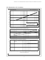
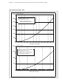
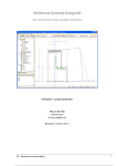
ANNEX: 12.3 PERFORMANCE CHARACTERISTICS/PRESSURE LOSSES
12.3.1 Characteristics ..40C / 2 condensers
Wasseraustrittstemperatur
in [°C]
Water outlet temperature
[°C]
Heating capacity
[kW]
Heizleistung
in [kW]
70
35
50
60
50
40
30
20
Bedingungen:
Conditions:
Heating water flow 3500
Heizwasserdurchsatz
2,9 l/h
m³/h
Cold water flow
Soledurchsatz
8,49500
m³/hl/h
10
0
Performance figure
in heating
operation
(incl. pump
power consumptions)
Leistungszahl
im Heizbetrieb
(incl.
der anteiligen
Pumpenleistungen)
8
35
7
6
5
5
4
3
2
1
0
Power consumptionin[kW]
power consumptions)
Leistungsaufnahme
[kW](incl.
(incl.pump
der anteiligen
Pumpenleistungen)
12
5
10
35
8
6
4
2
0
-10 -8
-6
-4
-2
0
2
4
6
8
10 12 14 16 18 20 22 24 26
Soleeintrittstemperatur
in [°C]
Cold
water inlet temperature
[°C]
15
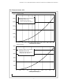
ANNEX: 12.3 PERFORMANCE CHARACTERISTICS/PRESSURE LOSSES
12.3.2 Characteristics ..40C / 1 condenser
Wasseraustrittstemperatur
in [°C]
Water outlet temperature
[°C]
Heating capacity
[kW]
Heizleistung
in [kW]
40
35
35
50
30
25
20
15
Bedingungen:
Conditions:
Heating water flow 3500
Heizwasserdurchsatz
2,9 l/h
m³/h
Cold water flow
Soledurchsatz
8,49500
m³/hl/h
10
5
0
Performance figure
in heating
operation
(incl. pump
power consumptions)
Leistungszahl
im Heizbetrieb
(incl.
der anteiligen
Pumpenleistungen)
10
9
8
7
6
5
4
3
2
1
0
35
50
Power
consumption in
[kW]
power consumptions)
Leistungsaufnahme
[kW](incl.
(incl.pump
der anteiligen
Pumpenleistungen)
8
6
50
35
4
2
0
-10 -8
-6
-4
-2
0
2
4
6
8
10 12 14 16 18 20 22 24 26
Kaltwassereintrittstemperatur
[°C]
Cold water inlet temperature in
[°C]
16
ANNEX: 12.3 PERFORMANCE CHARACTERISTICS/PRESSURE LOSSES
12.3.3 Pressure losses ..40C
Pressure loss in
[Pa]
Druckverlust
[Pa]
35000
Druckverluste
Pressure
losses in Verdampfer
the evaporator
Water/water
40C at30C
10°C
Sole/Wasser
bei 10°C
30000
Pressure loss 0,175 bar at
Druckverlust 15 kPa bei
nominal cold water flow 9500 l/h
25000
Sole-Nenndurchfluß 8,4 m³/h
20000
15000
10000
5000
0
0
1
2
3
4
5
6
7
8
Cold water flow 1000l/h
Kaltwasserdurchfluß
in [m³/h]
9
10
11
12
Pressure
loss in
[Pa]
Druckverlust
[Pa]
30000
Druckverluste
Verflüssiger
Pressure
losses in
the liquefier
Sole/Wasser
bei 10°C
Water/water
40C 30C
at 35°C
25000
Pressure loss 0,14 bar at nominal
Druckverlust 9 kPa bei
heating water flow 3500 l/h
20000
Heizwasser-Nenndurchfluß 2,9 m³/h
15000
10000
5000
0
0
0,5
1
1,5
2
2,5
3
Heizwasserdurchfluß
in [m³/h]
Heating water flow [l/h]
17
3,5
4
4,5
5
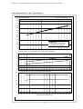
ANNEX:12.3PERFORMANCECHARACTERISTICS/PRESSURELOSSES
12.3.4 Characteristics ..90C / 2 condensers
Wasseraustrittstemperatur
in [°C]
Water outlet temperature
[°C]
Heating
capacity
[kW]
Heizleistung
in [kW]
130
120
110
35
50
100
90
80
70
60
50
40
Bedingungen:
Conditions:
Heizwasserdurchsatz
6,0 l/h
m³/h
Heating water flow 8000
Cold water flow
20000
Soledurchsatz
16,0
m³/hl/h
30
20
10
0
Performance
in heating(incl.
operation
(incl. pump
power consumptions)
Leistungszahlfigure
im Heizbetrieb
der anteiligen
Pumpenleistungen)
8
7
35
6
5
5
4
3
2
1
0
Leistungsaufnahme in [kW] (incl. der anteiligen Pumpenleistungen)
25
5
20
35
15
10
5
0
-10 -8
-6
-4
-2
0
2
4
6
8
10 12 14 16 18 20 22 24 26
Cold
water inlet temperature
[°C]
Soleeintrittstemperatur
in [°C]
18
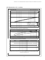
ANNEX: 12.3 PERFORMANCE CHARACTERISTICS/PRESSURE LOSSES
12.3.5 Characteristics ..90C / 1 condenser
Wasseraustrittstemperatur
in [°C]
Water outlet temperature
[°C]
Heating
capacity
[kW]
Heizleistung
in [kW]
100
90
35
50
80
70
60
50
40
30
Bedingungen:
Conditions:
Heating water flow 8000
Heizwasserdurchsatz
6,0 l/h
m³/h
Cold water flow
20000
Soledurchsatz
16,0
m³/hl/h
20
10
0
Leistungszahl
Heizbetrieb
(incl.
der anteiligen
Pumpenleistungen)
Performance im
figure
in heating
operation
(incl. pump
power consumptions)
8
7
35
6
5
50
4
3
2
1
0
Power consumptionin[kW]
power consumptions)
Leistungsaufnahme
[kW](incl.
(incl.pump
der anteiligen
Pumpenleistungen)
12
10
8
5
6
35
4
2
0
-10 -8
-6
-4
-2
0
2
4
6
8
10 12 14 16 18 20 22 24 26
Kaltwassereintrittstemperatur
[°C]
Cold water inlet temperature in
[°C]
19
ANNEX: 12.3 PERFORMANCE CHARACTERISTICS/PRESSURE LOSSES
12.3.6 Pressure losses ..90C
Pressure loss in
[Pa]
Druckverlust
[Pa]
35000
Druckverluste
Pressure
losses in Verdampfer
the evaporator
Sole/Wasser
bei 10°C
Water/water
90C at70C
10°C
30000
Pressure
loss 0,190
at bei
Druckverlust
12,5bar
kPa
nominal cold water flow 20000 l/h
25000
Sole-Nenndurchfluß 16,0 m³/h
20000
15000
10000
5000
0
0
2
4
6
8
10
12
14
16
18
Kaltwasserdurchfluß
in [m³/h]
Cold water flow 1000l/h
20
22
24
26
Pressure
loss in
[Pa]
Druckverlust
[Pa]
20000
Druckverluste
Verflüssiger
Pressure
losses in
the liquefier
Water/water
90C 70C
at 35°C
Sole/Wasser
bei 10°C
Pressure loss 0,13 bar at nominal
Druckverlust 6 kPa bei
heating water flow 8000 l/h
15000
Heizwasser-Nenndurchfluß 6,0 m³/h
10000
5000
0
0
1
2
3
4
5
6
Heating
water
flow
[l/h]
Heizwasserdurchfluß in [m³/h]
20
7
8
9
10
21
PE
N
L
X1
X1
X1
1
F1
1
2
1
3
X8
1 4
3 6
1 4 7
3 6 9
H2
X13-1
X13
A2
K2 A1
X11
X1-N11
X1-11
X11-2
7
11
3
15
1
X2-23
16
2
10
14
6
X11-8
X12-14
A2
K17 A1
X4 / X12
X2
X1
F10 F>
X2-24
X12-9
1
3
5
13
K2
X2-11
X2-10
2 /3.6
4 /3.6
6 /3.6
14 /-.5
E11
X12-15
E10
X11-9
X11-7
X2-N
22
K14
X1-24
A6
X1-23
21
K5
31
16
18
K17
X2-N
22
K14
15 /-.5
32
31
32
P<
B
X13-3
H3
X13-2
X8-3
X12-5
X2-19
F3
X2-17
X11-6
X8-1
X11-4
X12-13
K5
21
1
Q1
13
4
X12-10 X12-1
X2-14
4
X1-22
2 X2-16
A5
X1-20
EGS
X12-12
F6 T
X2-15
X12-6
X11-3
X1-21
MSZ
X11-1
3
A
X2
C
14
X1
<
2
X2-18
X12-4
X8-2
21
31
43
1
3
5
13
24
21
K5
22 /-.3
32 /-.4
44 /-.6
2 /3.4
4 /3.5
6 /3.5
14
A2
K5 A1
K15
24
21
14
13
21
31
43
1
3
5
13
A2
K14 A1
K16
K2
X1-19
14
11
B
X2-21
P>
16
X2-20
K17
22 /-.3
32 /-.4
44 /-.6
2 /3.4
4 /3.5
6 /3.5
14
X1-N12
X1-12
X8-6
X12-11
K14
X8-4
X1-18
X1-17
K16
X12-2
A4
F2
K15
5
C
A
11
X2-22
18
15
14
K5
K14
X12-3
44
43
X1-14
X1-13
X1-16
12
14
22
24
32
34
42
44
41
31
21 /-.4
11 /-.5
A2
A1
K15
K15
X8-5
44
43
X1-15
6
12
14
22
24
32
34
42
44
K16
A2
K16 A1
41
31
21 /-.5
11 /-.5
9
8
3
o.F.
o.F.
o.F.
o.F.
o.F. = ohne Funktion bei WPR-Betrieb
Heat
pump control
Wärmepumpenregler
11
12
3
10
14
13
9
8
2
4
8
o.F.= no funktion to heat pump control
L 11
L 12
MSZ 16
EGS
N 10
Verd.2 14
Verd.1 13
HD
Anford.
2
4
X4
1
1
Cod.
5
6
6
ND
5
7
7
EGS
0V
15
7
BOSUP 15
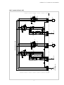
ANNEX: 12.4 CIRCUIT DIAGRAMS
12.4.1 Control ..40C
3/PE 400V
Mains
Netz
50Hz
3
X1
PE
L3
L2
L1
22
X1
PE
2
4
4
S
V
2
R
U
3
Bl.4 / X2-1;2;3;PE
1
3
4
2
1
3
1
W
N7
PE
4
X1
5
4
V
S
4
3
4
3
6
Bl.4 / X2-4;5;6;PE
U
R
T
1
2
1
2
K5
F8
6
5
6
5
Basic
control
unit - Load
Basissteuerung
- Last
W
T
6
5
6
5
N8
K14
F9
X1
PE
3
7
3
8
M
2
4
4
K2
22 14 / 1.4
/ 2.4
21 13
Q 1 /3,2-5A
( optional )
Brine
circulating pump
Soleumwälzpumpe
9
5
6
I> I> I>
1
ANNEX: 12.4 CIRCUIT DIAGRAMS
12.4.2 Control of load ..40C
23
Verdichter1
Condenser 1
M
3
M1
PE
3
X2
2
PE
M
3
5
6
Verdichter2
Condenser 2
4
4
Bl. 3 / X1-4,5,6,PE
X2
1
4
Bl. 3 / X1-1,2,3,PE
M2
Terminal
box
Anschlusskasten
Lastleitungen zur Basissteuerung
Cables to
basic
control
unit are
sind
bauseits
zu erstellen
by customers to prepare
X2
PE
13
N
14
E11
11 PE
15
Ölsumpf-Heizungen
Crank
pit heater
for condenser
E10
10
X12
Heat pump
Wärmepumpe
N
F6
Thermostat
Frostschutz
for freeze
protection
T<
2
4
A
C
F3
P<
B
17 18 19
1
5
R
PE
11
A
B
F2
P>
C
20 21 22
2
3
X4
PE
Pressostat
for
Pressostat
for low
HD-Wächter
ND-Begrenzer
pressure limiter with hight pressure
manual reset
4
1
10
15 16 PE
6
14
12
Zubehör:
Accessories:
Control
cable
Steuerleitung
15
Bl. 1u.2 / X8+X11
ANNEX: 12.4 CIRCUIT DIAGRAMS
12.4.3 Heat pump ..40C
L
3
Mains
load
Netz-Last
3/PE 400V
50Hz
4
L
2
24
X2 PE 1 2 3 PE 4 5 6
M3
M
3
N
N
PE
PE 12
12
11
A4
A5
A6
PE PE 13 14 15 16 17 18 19 20 21 22 23 24
Betrieb mit
Wärmepumpenregler
Operation
with
heat pump control
Anschlusskasten
Wärmepumpe
Heat pump terminal box
Solepumpe
Brine
pump
Wärmepumpe
M2
M1
Verdichter
Verdichter Condenser
Condenser
AnschlusskastenHeat pump
terminal box
X1 PE L N PE 1 2 3 PE 4 5 6 PE 7 8 9 11
X12
X8
X11
X4
N3
H2
Anschlusskasten
H3
X13
Wärmepumpe
Heat
pump terminal box
Wärmepumpenregler
Heat
pump controler
Steuerleitung
Control
cable
L
1
Control
cable
Steuerleitung
PE
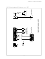
ANNEX: 12.4 CIRCUIT DIAGRAMS
12.4.4 Terminal assignment incl. heat pump control ..40C
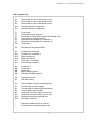
ANNEX: 12.4 CIRCUIT DIAGRAMS
12.4.5 Legend ..40C
A4
A5
A6
Wire jumper for use of heat pump control
Wire jumper for use of heat pump control
Wire jumper for use of heat pump control
E10
E11
Crank pit heater for condenser 1
Crank pit heater for condenser 2
F1
F2
F3
F6
F8
F9
F10
Control fuse
Pressostat for high pressure
Pressostat for low pressure limiter with manual reset
Thermostat for freeze protection
Automatic circuit breaker for condenser 1
Automatic circuit breaker for condenser 2
Flow switch
H3
Pilot lamp for low pressure fault
K2
K5
K14
K15
K16
K17
K11
Contactor for well pump
Contactor for condenser 1
Contactor for condenser 2
Relay condenser 1
Relay condenser 2
Time relay - flow switch
EVU blocking contactor**
M1
M2
M3
M5
M6
Condenser 1
Condenser 2
Well pump*
Buffer charging pump**
Hot water circulating pump**
N3
N7
Heat pump control*
Soft start control
Q1
Power breaker for brine circulating pump
X1
X2
X4
X8
X11
X12
X13
Terminal strip for mains supply
Terminal strip for heat pump (terminal box)
Control cable connector (N3)
Heat pump connector (basic control unit)
Heat pump connector (basic control unit)
Heat pump connector (terminal box)
Pilot lights connector
*
**
Optionally usable devices or controls
Components are to be provided on site
25
26
1
3
5
13
2 /2.4
4 /2.4
6 /2.5
14 /-.5
1
3
5
13
A2
A2
K2
K3 A1
44
43
14
K2 A1
A1
K14
K5
13
K3
2 /2.7
4 /2.8
6 /2.8
14
X12-13
X11-7
X2-N
F5
L
L
N
N
X11-8
X11-9
K5
X8
1 4
3 6
3 6 9
X2-N
E11
X2-11
X12-15
32
31
X11
X2-N
E10
X2-10
K14
X11-4
2 X2-16
1
1 4 7
X12-14
X2-30
X2-31
F11
X2-14
4
X12-12
F6 T
X2-15
X12-6
X11-3
22
7
21
3
11
15
1
16
2
X4 / X12
10
6
14
21
1
3
5
13
B
X2-17
K5
X2-32
C
2 /2.3
4 /2.3
6 /2.3
14/-2
X2-18
K15
21
22 /-.3
1
3
5
13
A2
K5 A1
K5.1
15
K15.1
31
1
3
5
43
A2
K5.1 A1
16
2 /2.3
4 /2.3
6 /2.3
14
18
14
16
14
21
14
13
K14
32 /-.3
2 /2.6
4 /2.7
6 /2.7
44
A2
1
3
5
13
11
Q4
21 /-.5
A2
15 /-.5
K15.1
K15
16
18
12
14
F13
1
X8-5
14
K15.1 A1
X12-3
A2
K15 A1
14
2 /2.6
4 /2.6
6 /2.6
14
K14.1
A2
Q3
X2-22
11
K16.1
C
A
K14 A1 K14.1 A1
18
15
K16
K2
X8-6
X12-11
B
A
X12-2
X8-4
X2-20
P>
F2
Q2
14
X2-21
11
X2-33
P<
F3
X12-4
X8-2
Q1
14
F11
X2-34
F5
X2-35
X12-1
X8-1
11
21 /-.5
A2
9
5
1
6
o.F.
o.F.
o.F.
o.F.
o.F.
o.F. = ohne Funktion bei WPR-Betrieb
o.F.= no funktion to heat pump control
HeatWärmepumpenregler
pump control
12
L 12
14
13
3
2
11
9
8
4
5
10
X4
6
1
N 10
Verd.2 14
Verd.1 13
HD
0V
Cod.
1 ND
7
15 /-.5
K16.1
K16
16
18
12
14
A2
K16 A1 K16.1 A1
F12
2
2
15
EGS
7
BOSUP 15
ANNEX: 12.4 CIRCUIT DIAGRAMS
12.4.6 Control ..90C
27
3
L1 L2 L3 PE
Mains
Netz
3/PE 400V
X1
50Hz
X1
PE
/1.5
U
2
F12
4
V
4
S
2
R
3
3
W
T
6
5
N7
Bl.4 / X2-1;2;3;PE
1
2
-/1.7
1
K5.1
1
3
2
1
4
3
5
6
5
I> I> I>
1
/1.5
K5
14
PE
7
1
3
5
Q1
12 / 1.5
/1.6
K14.1
1
4
3
6
5
X1
8
M
3
2
4
4
14
/1.2
K2
M3*
9
6
I> I> I>
11
X1
PE
U
5
F13
V
4
S
W
6
T
Bl.4 / X2-4;5;6;PE
4
2
-/1.7
1
2
R
N8
2
1
4
3
I> I> I>
6
5
/1.5
X1
PE
12 / 1.6
K14
14
11
5
11
3
Q4
1
Q3
12 / 1.6
Basissteuerung
Last
Basic control
unit - -Load
3
4
M
3
4
71 81 91
2
5
/1.2
K3
14
11
Q2
M4*
6
I> I> I>
1
12 / 1.5
ANNEX: 12.4 CIRCUIT DIAGRAMS
12.4.7 control of load ..90C
28
M1
Verdichter1 1
Condenser
M
3
PE
3
PE
2
X2
M
3
5
6
M2
N
11 PE
15
for condenser
PE
X12 14
N
Heat
pump
Wärmepumpe
E10
E11
Crank pit heater
Ölsumpf-Heizungen
10
X2
Terminal
box
Anschlusskasten
Verdichter2 2
Condenser
4
4
Bl. 3 / X1-4,5,6,PE
X2
1
4
Bl. 3 / X1-1,2,3,PE
Cables
to basic
control unit are
Lastleitungen
zur Basissteuerung
bauseits zu to
erstellen
bysind
customers
prepare
for freeze
protection
F6
Thermostat
Frostschutz
T<
P<
B
5
R
PE
F3
Pressostat
for low
ND-Begrenzer
Rückstellung
pressure
limitervonwith
manualHand
reset
C
A
2
4
1
4
17 18 19
10
15 16 PE
12
14
6
Accessories:
Zubehör:
Control
cable
Steuerleitung
15
Bl. 1u.2 / X8+X11
11
3
B
P>
C
F2
Pressostat
HD-Wächter for
Rückstellung
hight
pressure
selbsttätig
A
20 21 22 PE
2
31
N
L
N
32
M2 F5
33
M1
34
M2 F11
35
M1
F11
Electronic
winding
protection
Elektronischer
Wicklungsschutz
Verdichter 1 Verdichter 2Verdichter 1 Verdichter 2
F5
N
L
N
1
Condenser 1 Condenser 2 Condenser 1 Condenser 2
30
13
X4
ANNEX: 12.4 CIRCUIT DIAGRAMS
12.4.8 Heat pump ..90C
3/PE 400V
Mains
load
Netz-Last
4
29
5
6 PE 7
M
3
8
M
3
9 PE 71 81 91
Betrieb mitwith
Wärmepumpenregler
Operation
heat pump control
Wärmepumpe
Heat
pump terminal box
Anschlusskasten
M3
M4
Solepumpen
Brine
pump
For
pump
Beibrine
Betrieb
mitoperation
einer Solepumpe,
always
to 7;8;9;PE
immer connect
an 7;8;9;PE
anschliessen
X2 PE 1 2 3 PE 4 5 6
50Hz
3 PE 4
Wärmepumpe
M1
M2
Verdichter Condenser
Verdichter
Condenser
2
HeatAnschlusskastenpump terminal box
PE 1
X12
X8
X11
N3
Wärmepumpe
Heat
pump terminal box
Anschlusskasten
Wärmepumpenregler
Heat
pump controler
Steuerleitung
Control cable
X4
Steuerleitung
Control
cable
L L L
X1 PE
1 2 3
ANNEX: 12.4 CIRCUIT DIAGRAMS
12.4.9 Terminal assignment incl. heat pump control ..90C
ANNEX: 12.4 CIRCUIT DIAGRAMS
12.4.10 Legend ..90C
E10
E11
Crank pit heater for condenser 1
Crank pit heater for condenser 2
F2
F3
F5
F6
F10
F11
F12
F13
Pressostat for high pressure detector
Pressostat for low pressure limiter
Electronic winding protection for condenser 1
Thermostat for freeze protection
Flow switch
Electronic winding protection for condenser 2
Temperature detector / N7
Temperature detector / N8
K2
K5
K5.1
K14
K14.1
K15
K15.1
K16
K16.1
Contactor for well pump (M3)
Contactor for condenser 1
Starter contactor for condenser 1
Contactor for condenser 2
Starter contactor for condenser 2
Relay for condenser 1
Time-delay relay K5
Relay for condenser 2
Time-delay relay K14
M1
M2
M3
Condenser 1
Condenser 2
Well pump *
N3
N7
N8
Heat pump control*
Soft start PC board for condenser 1
Soft start PC board for condenser 2
Q1
Q2
Q3
Power breaker for well pump (M3)
Power breaker for condenser 1
Power breaker for condenser 2
X1
X2
X4
X8
X11
X12
Terminal strip for basic control unit
Terminal strip for heat pump (terminal box)
Control cable connector (N3)
Heat pump connector (basic control unit )
Heat pump connector (basic control unit )
Heat pump connector (terminal box)
*
**
Optionally usable components, devices or controls
Components are to be provided on site
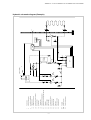
30
Hot water supply
Hot water control / sensor
Return line sensor
External wall probe
Brine pump
Return flow collector
Ground absorber
Heat pump
Heat pump control
Electric distribution pane
25
26
33
34
42
44
45
WP
WPR
EV
Thermostat valve
19
Cold water supply
Overflow valve
18
24
Non- return valve
17
Safety valve
Structure- borne noise insulation
16
23
Flexible connection hoses
15
Shutoff valve for manual operation
Expansion vessel
12
Shutoff valve for manual operation and drain
Hot water circulating pump
5
21
Heating circulating pump
2
20
Heat consumer
1
23
20
17
20
31
N06
(WUP)
5
24
20
17
20
25
T
26
N05
(HUP)
2
Hot water storage
20
WWF
B3
18
19
16
23
Warmwasserspeicher
12
20
15
1
15
21
(RLR)
B2
WP
15
20
T
33
BufferPufferspeicher
storage
15
21
20
WPR
23
12
EV
20
20
42
T
44
43
34
20
20
45
ANNEX: 12.5 HYDRAULIC SCHEMATIC DIAGRAM
Hydraulic schematic diagram (Example)
ANNEX: 12.6 CE CONFORMITY STATEMENT
CE CONFORMITY CERTIFICATE
CE
The undersigned
EC Conformity Certificate
KKW Kulmbacher Klimageräte-Werk GmbH
Dimplex Divisiom
Am Goldenen Feld 18, 95326 Kulmbach, Germany
confirms that the unit(s) listed below comply with the requirements stipulated in the EC guidelines owing to their
design and type and to the versions put on the market.
Any modifications of the unit(s) that are performed without our consent renders this certificate ineffective.
Name of the unit(s)
EC Guidelines
Brine/water heat pumps
for indoor installation with R407C
Water/water heat pumps
for indoor installation with R407C
EC guideline on low voltage (73/23/EEC)
EC Guideline on EMC (89/336/EEC)
Printing equipment guideline (97/23/EEC
Type:
Harmonized EN
SI 30CG
EN255:1997
SI 70CG
EN 378:1994
DIN EN 603335-1 (VDE 0700, part I):1995-10
EN 60335-1:1994 +A11:1995
WI 40CG
DIN EN60335-1/A1 (VDE 0700, part 1/A1):1997-08
EN 60335 1/A1:1996
WI 90CG
DIN EN 60335-1/A12 (VDE 0700, part 1/A12):1997-08
DIN EN 60335-1/A13 (VDE 0700, part 1/A13):1998-12
DIN EN 60335-1/A14 (VDE 0700, part 1/A14):1999-05
DIN EN 60335-2-40 (VDE 0700, part 40):1998-07
DIN EN 55014-2 (VDE 0875, part 14-2):1997-10
Requirements of category II
DIN EN 55014-1 (VDE 0875, part 14-1):1999-10
1:1993+A1:1997+A2:1999
DIN EN 61000-3-2 (VDE 0838, part 2):1998-10
EN60335-1/A12:1996
EN60335-1/A13:1998
EN60335-1/A14:1998
EN60335-2-40:1997
EN 55014-2:1997
EN 55014EN 61000-3-2:1995+
Corrigendum:1997+A1:1998+A2:1998
DIN EN 61000-3-2/A14 (VDE 0838, part 2/A14):2001-01 EN 61000-3-2:1995/A14:2000
DIN EN 61000-3-3 (VDE 0838, part 3):1996-03
EN 61000-3-3:1995
Order number:
337
337
337
337
800
810
820
830
Kulmbach, May 07, 2002
National standards/guidelines
D
VBG20
Wolfgang Weinhold
Managing Director
32
A
CH
SVT1
Mathias Huprich
Technical Manager
ANNEX: 12.7 WARRANTY CERTIFICATE/CUSTOMER SERVICE
Warranty certificate (valid in Germany)
The following conditions, which describe the terms and
conditions of our warranty, do not affect the obligations of
the vendor to honor the warranty as specified in the sales
contract with the end user. For the units, we offer warranty
in accordance with the conditions below:
An extension of the warranty to 36 months for heating heat
pumps and central ventilating systems, however a maximum
of 38 months from the date of delivery from the factory, will
be granted in accordance with the following conditions:
prerequisite for the granting of the extended warranty is
the commissioning, subject to cost, by the authorized system
engineering customer service, with the commissioning
certificate, within a time of operation (compressor running
time) of less than 150 hours. Defects reported in the
commissioning certificate must be eliminated without delay.
This constitutes the basis for the warranty. The
commissioning certificate must be sent to the address below,
from which the warranty period extension is also confirmed,
within one month of successfully commissioning the unit.
We remedy defects to the unit which are demonstrated to
be the result of material or manufacturing faults when we
are notified of these immediately following the discovery of
such defects and within 24 months following delivery to the
end user free of charge, subject to the following proviso. In
the event that the defect becomes apparent within 6 months
following delivery and commissioning (heating heat pump
and central apartment ventilating systems) has been
successfully performed by the authorized system
engineering customer service, it can be assumed that the
cause is a material or manufacturing fault.
The charge for commissioning includes the commissioning
itself and the costs of travel. No liability can be assumed for
proper planning, dimensioning and the performnce of work
on the overall system. The elimination of defects in the
overall system and the service times required are special
services.
The warranty conditions apply to this unit only when it is
purchased by a contractor in one of the member countries
of the European Union, is operated in Germany during the
time at which the defect occurs, and warranty services
can be performed in Germany.
The commissioning charge, which is currently 320 net for
heating heat pumps and 450 net for ventilating systems,
both per unit, is invoiced to the contractor by the system
engineering customer service. We reserve the right to make
adjustments to these prices.
The elimination of the defects which we recognize as
legitimate claims against warranty encompasses, subject
to our choice, the repair or replacement by flawless parts
of the defective parts. We cannot assume extraordinary
repair costs arising from the type or location or poor
accessibility of the unit. Removed parts which we take
back become our property. The warranty period for the
rectification of defects and replacement parts ends with
the elapsing of the original warranty period for the unit. The
warranty does not extend to fragile parts which only impair
the value or the usefulness of the unit insignificantly. The
original proof of purchase must always be presented.
In the event that customer service is required, the authorized
system engineering customer service responsible for the
customer site must be informed and will provide fast help to
deal with the problem. The authorized system engineering
customer service responsible for your region can be
determined by contacting the service hotline for the Dimplex
Division of the KKW Kulmbacher Klimageräte-Werk GmbH.
KKW Kulmbacher Klimageräte-Werk GmbH
Dimplex Division
System Engineering Customer Service
Am Goldenen Feld 18
95326 Kulmbach
Germany
The warranty conditions cannot be honored if the end user
or a third party fail to comply with the corresponding VDE
provisions, the provisions of the local power supply
companies, or our installation and operating instructions,
as well as the notes or interconnection diagrams in the
configuration documentation, or if the accessories required
from us to implement a function are not used. In the event of
unauthorized modifications or work performed by the end
user or a third party, the manufacturer is no longer liable for
the resulting consequences. The warranty extends to the
unit and the parts provided by the supplier. Parts not delivered
by the supplier and unit/system defects attributable to the
use of parts not provided by the supplier do not fall under
warranty claims.
Telephone:
Fax:
e-mail:
Internet:
+49 (0) 9221 709 562
+49 (0) 9221 709 565
[email protected]
[email protected]
w w w.kkw.de
www.dimplex.de
The product number (E.Nr.) and the date of production (FD)
of the unit are required in order to process the order. This
information is given on the nameplate in the field marked
with the heavy border.
In so far as we are not able to eliminate the defect, or we
reject the rectification thereof or unreasonably delay the
implementation thereof, the manufacturer will deliver a
replacement unit free of charge or remunerate the reduced
value. In the case of a replacement delivery, we reserve
the right to make appropriate allowance for the use of the
unit up to this time. Additional or more extensive claims, in
particular such claims resulting the replacement of damage
to objects other than the unit are, provided that liability has
not been compulsorily ordered by law, excluded.
.Customer service address
33
Notes
34
Notes
35
KKW Kulmbacher Klimageräte-Werk GmbH
Dimplex Division
Am Goldenen Feld 18
D-95326 Kulmbach, Germany
Technical modifications reserved
Telefax (0 92 21) 709-589
www.dimplex.de
36