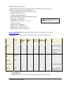
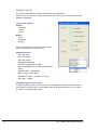
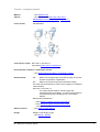
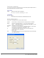
1
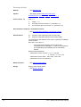
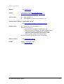
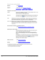
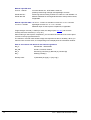
Reinforced Concrete Design B2 User manual for Frilo design calculation applications © Friedrich + Lochner GmbH 2011 Frilo on the web www.frilo.com E-mail: [email protected] B2 Manual, revision 1/2011 B2 - Reinforced concrete design 1 Frilo application: B2 - Reinforced concrete design This manual deals with the basic features of the B2 application. Contents Application options............................................................................................................... 3 Standards and terms............................................................................................................... 4 Information concerning the standards..................................................................................... 4 Basis of calculation .............................................................................................................. 5 System input ......................................................................................................................... 6 T-beam / rectangle uniaxial..................................................................................................... 7 Cast-in-place complement ...................................................................................................... 8 Layers cross section input ...................................................................................................... 8 Layers cross section input ...................................................................................................... 9 Rectangle biaxial................................................................................................................... 10 Circle / annulus ..................................................................................................................... 11 General cross section biaxial ................................................................................................ 12 Material input ........................................................................................................................ 13 Concrete - user-defined (DIN 1045-1, EN 1992 1-1) ....................................................... 15 Reinforcing steel - user-defined (DIN 1045-1, EN 1992 1-1) ........................................... 15 Input of action-effects......................................................................................................... 16 Action-effect table ................................................................................................................. 17 Environmental conditions / requirement classes ............................................................ 18 Control of the crack width proof ............................................................................................ 18 Control of the design .......................................................................................................... 19 Design - results ..................................................................................................................... 19 Fire protection parameters .................................................................................................... 21 Design for polygonal cross sections...................................................................................... 22 Design configuration ............................................................................................................. 23 Design options DIN 1045 7/88 .............................................................................................. 26 Design options DIN 1045-1 ................................................................................................... 26 Design options ÖNORM B4700 ............................................................................................ 27 Design options EC2 (Italy) .................................................................................................... 27 Design options British Standard BS 8110 ............................................................................. 28 Design options EN 1992 1-1 ................................................................................................. 28 Output .................................................................................................................................. 29 Output profile ........................................................................................................................ 29 Text view............................................................................................................................... 29 Graphic view ......................................................................................................................... 29 Literature ............................................................................................................................. 29 Further information and descriptions are available in the relevant documentations: Analyses on Reinforced Concrete Cross Sections.pdf Durability - Creep Coefficient and Shrinkage Strain.pdf 2 Frilo - Statics and Structural Analysis Application options The application B2 is intended for the design and structural analysis of steel concrete cross sections in accordance with the following standards: - DIN 1045 7/88, DIN 1045-1 (2001), DIN 1045-1 (2008) - ÖNORM B 4700 (2001-06-01) - Eurocode 2 (NAD Italy 02/1996) - British Standard BS 8110 (1997) and BS 8500-1 (2001) - DIN EN 1992 1-1 (Draft 2008) * ) *) One National Appendix is included in the programmprice, additional NA´s are available (see pricelist). ) - BS EN 1992 1-1 (NA 2004) * ) - ÖNORM EN 1992 1-1 (B 1992 1-1 (2007)) * ) - EN 1992 1-1 (2004) * - UNI EN 1992-1-1/NTC:2008 * ) - NEN EN 1992-1-1:2005/NB:2007 * ) - NBN EN 1992-1-1 ANB 1e uitg., 2010 * ) ) - CSN EN 1992-1-1/NA: Cervenec 2007 * You can select the desired standard as a start option via the function "Standard" in the dialog "Design configuration". The following table gives an overview of the optional scope of calculation for each type of cross section: Cross section Effect of actions ULS bending + longitud. force ULS/SLS effective rigidity ULS Stress Crack width Comments analysis proof shear force reinf./concre + torsion te Tbeams Uniaxial X X X X Rectangle 1 Uniaxial X X X X (1) Cast-in-place concrete joint/with lattice girders (2) Cast-in-place concrete joint/with lattice girders (2) n/m diagrams Rectangle 2/ Uniaxial and biaxial X X (2) X _ Uniaxial and biaxial X X (1) X (1) n/m diagrams layers cross section Uniaxial X X X X X Cast-in-place concrete joint/with lattice girders (2) General cross section Uniaxial and biaxial X X - - - (Additional module!) box Circle/ annulus Rigidity for the design situation "fire": (3) (1) except BS 8110 (2) only DIN 1045-1 (3) Rectangle and circle cross sections with general reinforcement, only DIN 1045-1 B2 - Reinforced concrete design 3 Standards and terms DIN 1045-1 If DIN 1045-1 (2008) is not explicitly mentioned, the term "DIN 1045-1" refers to to the version 2001 as well as the version 2008 of DIN 1045-1. EN 1992 1-1 If the national annexes are not mentioned explicitly, the statements apply to all national annexes in the same way. NDP The abbreviation refers to definable parameters in the national annex. The corresponding national annex should be taken into consideration. The following shortcuts are used for the individual national annexes: EN: recommended values EN 1992 1-1 NA_D: Germany NA_A: Austria NA_GB: UK NA_I Italy NA_NL Netherlands NA_B Belgium NA_CZ Czech Republic Information concerning the standards DIN 1045-1 The amendment 2008 is included in the List of Technical Construction Regulations 02/2008 and will be introduced in the Federal States in the beginning of 2009. EN 1992 1-1: NA_D: E DIN 1992 1-1/NA Please note that the current version has the status of a draft. The introduction of the standard is expected in the course of 2010. NA_A: ÖNORM B 1992 1-1 (2007) The Austrian Institute of Standardization will withdraw the currently applicable standard B4700 on 1 June 2009. Therefore, EN 1992 1-1 is the only state-of-the art standard at present (http://www.eurocode.at/) NA_GB: NA to BS EN 1992 1-1 (2004) In June 2008, the British Standard Institute adopted EN 1992 1-1, the standard BS 8110 applicable until then is no longer supported. (http://www.eurocodes.co.uk) NA_I: UNI EN 1992-1-1/NTC:2008 Even though the final version of this National Annex is not available yet, you can use the Eurocode in combination with the document "Norme tecniche per le costruzioni" (/56/) published on 4 February 2008 and the supplementary circular "Circolare finissima 2.2.2009" (/57/). NA_NL: NEN EN 01/01/1992/NB The Eurocode for the construction of buildings is applicable in the Netherlands. The coexistence period will last for one year after the introduction of the final version. (/53/) NA_CZ: 4 After publication of the National Annexes, the old national standards were withdrawn on 31 May 2010. Frilo - Statics and Structural Analysis Basis of calculation The topics - Design for bending and longitudinal force - Calculation of the effective rigidity - Shear design - Proofs of serviceability - Accidental design situation are dealt with in the document "Analyses on Reinforced Concrete Cross Sections.pdf". B2 - Reinforced concrete design 5 System input The items of the main tree reveal the input options of the application. When you set up a new item, a window for the selection of the type of cross section and the standard is displayed. Type of cross section: Uniaxial Rectangle T-beam Layers Biaxial Circle Rectangle Polygon Note: The processing of polygonal cross sections requires the additional module B2-Poly. Standard selection - DIN 1045 7/88 - DIN 1045-1/2001 - DIN 1945-1/2008 - ÖNORM B 4700/2008 - Eurocode 2 (NAD Italy 02/1996) - British Standard BS 8110 (1997) and BS 8500-1 (2001) - DIN EN 1992 1-1 (Draft 2008) - BS EN 1992 1-1 (NA 2005) - ÖNORM EN 1992 1-1 (B 1992 1-1 (2007)) - EN 1992 1-1 (2004) Change the type of cross section In order to change the type of cross section in an existing item, double-click on the desired cross section in the main tree. A confirmation dialog is displayed and allows you to confirm or cancel the overwriting of the data. 6 Frilo - Statics and Structural Analysis T-beam / rectangle uniaxial Material See Material input Options See design options DIN 1045, DIN 1045-1, ÖNORM B4700, EC2 Italy, BS 8110, EN 1992 1-1 Cross section See illustration Cast-in-place compl.: DIN 1045-1; EN 1992 1-1 (See dialog Cast-in-place complement ) Environmental conditions / requirement classes See Environmental conditions / requirement classes Reinforcement dob distance of the upper layer (from the top edge or the castin-place complement, if applicable) dun distance of the lower layer (from the bottom edge) You must specify the distance of the center of gravity for multilayer reinforcements. DIN 1045-1, EN 1992 1-1: The reinforcement distance should comply with requirements due to durability. In case of noncompliance, a corresponding note is displayed in the information window. Reinforcement distribution: - See Design according to the Kh (Kd) method - See Design for a given reinforcement relation Asu/Aso= 1, 3, 5, 7 Effect of actions See Input of action-effects Design Display of the design results See Design - Results. B2 - Reinforced concrete design 7 Cast-in-place complement You can enter cast-in-place complements for the cross section types rectangle uniaxial, Tbeam uniaxial and layers cross section uniaxial. Cross section Height: height of the cast-in-place complement hE <= hfo - 5 cm, if hfo = 0, then HErg <= h - 5 cm Joint finishing DIN 1045-1 (2001): In accordance with the definition in DAfStb Booklet 525 S.84 DIN 1045-1 (2008), EN 1992 1-1: Very smooth Cast against steel or smooth timber formwork. Smooth Screed surface or finished with slide or extruder process or untreated. Rough Exposure of aggregate skeleton >= 3 mm (40 mm distance approx.) Interlocked Interlocking according to figure 6.9 NA_D: or when dg>=16 mm and exposure of aggregate skeleton > 6 mm or sand surface process average peak-to-valley depth > 3 mm bj Accountable joint width, reduced in regard to the total width due to prefabricated formwork, if applicable. NA_D: or sand surface method, average peak-to-valley depth > 1.5 mm BFug <= beffo nEd 8 Lower design value of the normal force perpendicular to the joint per length unit, negative pressure. Frilo - Statics and Structural Analysis Layers cross section input Material See Material input Options See design options DIN 1045, DIN 1045-1, ÖNORM B4700, EC2 Italy, BS 8110, EN 1992 1-1 Cross section You can enter any simple symmetrical cross sections. Each layer has a distance from the top and a width. The distance of the first layer is equal to 0. Cast-in-place compl.: See dialog Cast-in-place complement only with DIN 1045-1 Thickness hE <= thickness of the first layer Joint width bj <= width of the first layer, additional BFug <= width of second layer, when HErg = thickness of first layer Environmental conditions / requirement classes See Environmental conditions / requirement classes Reinforcement dob distance of the upper layer (from the top level or the castin-place complement, if applicable) dun distance of the lower layer (from the bottom edge) You must specify the distance of the center of gravity for multilayer reinforcements. DIN 1045-1, EN 1992 1-1: The reinforcement distance should comply with requirements due to durability. In case of noncompliance, a corresponding note is displayed in the information window. Reinforcement distribution: - See Design according to the Kh (Kd) method - See Design for a given reinforcement proportion Asu/Aso= 1, 3, 5, 7 Effect of actions See Input of action-effects Design Display of the design results See Design - Results. B2 - Reinforced concrete design 9 Rectangle biaxial Material See Material input Options See design options DIN 1045, DIN 1045-1, ÖNORM B4700, EC2 Italy, BS 8110, EN 1992 1-1 Cross section bw width > 0 h height bi box width (full cross section = 0, otherwise > 0) >0 di box thickness (full cross section = 0, otherwise > 0) Environmental conditions / requirement classes See Environmental conditions / requirement classes Reinforcement b1 distance of the upper layer (from the top edge) d1 distance of the lower layer (from the bottom edge) You must specify the distance of the center of gravity for multilayer reinforcements. DIN 1045-1, EN 1992 1-1: The reinforcement distance should comply with requirements due to durability. In case of noncompliance, a corresponding note is displayed in the information window. Reinforcement distribution: - Distributed over the corners: 41/4, 31/6+3/6, 31/8+ 5/8, 31/10+ 7/10 - Distributed over the sides: Asli= Asre, Asu= Aso - Distributed over the circumference 10 Effect of actions See Input of action-effects Design Display of the design results See Design - Results. Frilo - Statics and Structural Analysis Circle / annulus Material See Material input Options See design options DIN 1045, DIN 1045-1, ÖNORM B4700, EC2 Italy, BS 8110, EN 1992 1-1 Cross section da outer diameter > 0 di inner diameter (full circle: Di=O, otherwise > 0) Environmental conditions / requirement classes See Environmental conditions / requirement classes Reinforcement d1 distance from the circumference > 0 DIN 1045-1, EN 1992 1-1: The reinforcement distance should comply with requirements due to durability. In case of noncompliance, a corresponding note is displayed in the information window (in case of multilayer reinforcements, higher distances are required for the resulting layer). The reinforcement is distributed over the circumference. Effect of actions See Input of action-effects Design Display of the design results See Design - Results. B2 - Reinforced concrete design 11 General cross section biaxial Material See Material input Options See design options DIN 1045, DIN 1045-1, ÖNORM B4700, EC2 Italy, BS 8110, EN 1992 1-1 Polygonal cross section Outline The input of the polygon is done by entering polygon points in a x/y system of coordinates into a table. You can enter up to 100 polygon points. Block-out Note: The polygon is entered via a table in the same way. This table can button on top of the table for the outline. be accessed via the Standard cross sections of B2 (rectangle, T-beam, layers cross section) can most efficiently be entered in the sections of the corresponding cross section types and converted into a polygonal cross section subsequently. Note concerning the input in the table: All entered coordinates are shown in the graphic window. The recalculation is only performed after you exit the table. You can terminate the input of data and exit the table by specifying zero in the column "current no." Environmental conditions / requirement classes See Environmental conditions / requirement classes General point reinforcement The reinforcement can comprise up to 100 reinforcement points. The x/y coordinates are entered via a table. You can optionally define a reinforcement point as a constant point, i. e. the area assigned to it once is not changed during the iteration. The definition of constant points is done via an enhanced table that is accessible by clicking on the button . In this section, you also define the selected reinforcement that is required for the calculation of the effective rigidity. Effect of actions See Input of action-effects Design See Results of polygonal cross sections The following cross section types are available for the fire protection proofs: - rectangle and general point reinforcement - circle and general point reinforcement 12 Frilo - Statics and Structural Analysis Material input The materials concrete/reinforcing steel are entered via standard-specific selection lists. Alternatively, you can freely define the material values via the menu item "Free" with DIN 1045-1 and EN 1992 1-1. You can select different materials for the longitudinal reinforcement and the stirrups. Material input DIN 1045 7/88 B15... B55 acc. to table 11 B65... B115 acc. to DafStb* directive for high-strength concretes BSt 1, 3, 4 different materials for the longitudinal and the stirrup reinforcement, if applicable Material input DIN 1045-1C12/15....C100/115 table 9 LC12/13...LC60/66 standard and high-strength concrete acc. to lightweight concrete acc. to table 10 additional input for cast-in-place complement, if applicable If high-strength concrete (> C50/60) is used, the design option "Ac net" (net concrete surface) should be selected (cf. /14/ p.161). When entering a cast-in-place complement, you can select the material of the cast-in-place concrete in the top right selection list. The selected concrete class should comply with requirements due to durability. When you select a lower concrete class, a corresponding note is displayed in the information window. BSt 420 SB bar steel acc. to DIN 488 old, standard ductility BSt 500 SA bar steel with standard ductility acc. to table 11 BSt 500 MA fabric steel with standard ductility acc. to table 11 BSt 500 SB bar steel with high ductility acc. to table 11 BSt 500 MB fabric steel with high ductility acc. to table 11 BSt 450 SE earthquake-resistant steel acc. to /5/ p.176 tab. 2.4 Material input EC2/Italy C12/15... C50/60 concrete classes acc. to table 3.1 Fe B22 k...Fe B44 k reinforcing steel acc. to NAD Italy /19/ p.17, table1-I and 2-I Material factors acc. to EC2 (Italy), table 1 Fundamental combination Accidental combination Concrete 1.6 1.3 Steel 1.15 1.00 Cf. /19/p. 68 for reinforced concrete and partially prestressed components. Material input ÖNORM B4700 B15...B60 old concrete classes (B4200-10) acc. to table 4 C12/15… C50/60 new concrete classes (Eurocode) acc. to table 4 Reinforcing steel acc. to table 5, different materials for the longitudinal and the stirrup reinforcement, if applicable. B2 - Reinforced concrete design 13 Material input BS 8110 C12/15... C50/60 concrete classes acc. to BS 8500-1 table 20, presently without high-strength and lightweight concrete Grade 250 RH... reinforcing steel according to BS 8110-1 table 3.1 and /20/table 1.3 Grade 485 WH different materials for the longitudinal and the stirrup reinforcement, if applicable Material input EN 1992 1-1C12/15....C100/115 standard concrete acc. to 3.1.3 and NA LC12/13...LC60/66 lightweight concrete acc. to 11.3.1 and NA, additional input of cast-in-place complement, if applicable If high-strength concrete (> C50/60) is used, the design option "Ac net" (net concrete surface) should be selected (cf. /14/ p.161). When entering a cast-in-place complement, you can select the material of the cast-in-place concrete in the top right selection list. The selected concrete class should comply with requirements due to durability. When you select a lower concrete class, a corresponding note is displayed in the information window. Steel in accordance with Annex C and national regulations 14 NA_D: BSt 500 SA ...Bst 500 MB NA_GB: B 500 A, B 500 B, B 500 C NA_A: Bst 500 (A), Bst 550 (A), Bst 600 (A), Bst 550 (B) NA_I: B450(A), B450(C) Ductility class: A (standard), B (high), C (very high) Frilo - Statics and Structural Analysis Concrete - user-defined (DIN 1045-1, EN 1992 1-1) Input of lightweight concrete - Tick the option "Lightweight concrete" - Enter the concrete density (> minimum density acc. to /5/ p.176 table 2.3) - Tick the option "Lightweight sand" if applicable Free input You can only enter the following values manually if the option "According to selected standard" is unticked. Otherwise, these values are set by default. factor for long-term effect partial safety coefficient Parabolic rectangular stress-strain diagram c2 strain when attaining full strength c2u strain under maximum load Exp n exponent fctm average tensile strength Ecm average module of elasticity Reinforcing steel - user-defined (DIN 1045-1, EN 1992 1-1) fyk yield point Ductility ductility classes Free input You can only enter the following values manually if the option "According to selected standard" is unticked. Otherwise, the steel properties are set by default. ftk/fyk standard ductility: 1.05, high ductility: 1.08, earthquake-resistant steel: 1.15 (see also /5/ p.176) s corresponding partial safety factor uk strain under maximum load su limit strain during design B2 - Reinforced concrete design 15 Input of action-effects Depending on the scope of calculation of the individual cross-section types ( see Application options) particular action-effect options are enabled or disabled. Alternatively, you can enter multiple action-effects also via the action-effect table. If several action-effects occur you can toggle between . these combinations via the buttons Nx longitudinal force, point of application in accordance with the Configuration, positive tension, negative compression My bending moment in y-direction, positive in accordance with the configuration Mz bending moment in z-direction, positive in accordance with the configuration Vy design shear force in y-direction, positive in accordance with the configuration Vz design shear force in z-direction, positive in accordance with the configuration T torsional moment Flexural design / shear force and torsion DIN 1045 7/88 service loads Otherwise ultimate limit state according to the selected design situation Crack width proof DIN 1045 7/88 frequent combination DIN 1045-1 quasi-permanent combination, special cases acc. to table 18 EC2 Italy quasi-permanent combination ÖNORM B4700 quasi-permanent combination BS 8110 currently not available EN 1992 1-1 quasi-permanent combination, special cases acc. to table 7.1 (NDP) Stress calculation (only via table) Nx longitudinal force, point of application in accordance with the configuration, positive tension, negative compression My bending moment, positive according to the configuration Mz bending moment, only with the cross section types rectangle biaxial and circle, positive according to the configuration DIN 1045-1/EC2 Italy/B4700, EN 1992 1-1: infrequent and quasi-permanent load combination Define the design situation DIN 1045-1 / ÖNORM B4700 / EC2-Italy / EN 1992 1-1: - permanent/transient - accidental - earthquake After having selected the situation(s) from this list, the entered action-effects of the ultimate limit state are assigned to the corresponding design situation(s). 16 Frilo - Statics and Structural Analysis Action-effect table If a cross section should be designed for more than one action-effect combination, you can use the action-effect table, which is available with all cross section types. Each action-effect combination holds a separate line in the table and you can enable it for subsequent calculation. Depending on the scope of calculation of the individual cross-section types ( see Application options), particular action-effect options are enabled or disabled. You can also enter the actions-effects required for the stress analysis in this section. If the load combination for the crack width proof corresponds to the quasi-permanent load combination (standard with reinforced concrete), the values in the corresponding columns are set automatically. In addition, you can enter the reinforcement selected for the rigidity calculation, the crack width proof and the stress analysis. If the value of the selected reinforcement is equal to zero, the result from the bending design is assumed. B2 - Reinforced concrete design 17 Environmental conditions / requirement classes With the exception of DIN 1045 7/88 (direct access) you can access the dialogs for the durability and the calculation of the creep coefficient and the shrinkage strain via the buttons durability/creep/shrinkage. ( See also the document Durability, creep coefficient and shrinkage strain) The button allows you to access the dialog for the control of the crack width proof. Environmental conditions DIN 1045 7/88 Selection of the environmental conditions according to table 10. The relevant crack width is internally assigned to the requirement class selected in line 1 ... line 4. Environmental conditions / creep coefficient and shrinkage strain EC2 (Italy) Uwk 1 ..Uwk5C Selection of the exposure classes according to table 4.1 (control of the permissible concrete stress). perm.wk. Selection of the permissible crack width for reinforced concrete components 0.3 mm, prestressed concrete components 0.2 mm and special requirements 0.15 mm. Environmental conditions / creep coefficient and shrinkage strain ÖNORM B4700 For reinforced concrete components: For special requirements: perm.wk = 0.3 mm perm.wk = 0.15 mm Durability / environmental conditions / creep coefficient and shrinkage strain (DIN 1045-1, EN 1992 1-1) When you exit the dialog by clicking OK, the entered values are matched to the durability requirements if they do not comply with them. Control of the crack width proof The button in the requirement classes (DIN 1045-1) or environmental conditions (EC2 Italy, ÖNORM B4700, EN 1992 1-1) section allows you to access this dialog. fcteff The option allows to modify the concrete tensile strength. Full strength after 28 days is set by default. Width of the effective zone of the tensile reinforcement Correspondingly, the width of the effective zone of the tensile reinforcement decisive for the crack width proof is limited in the slabs of T-beams according to /13/ p.145: beff(ZII) = 0,5 beff(ZI) + 2 cl with cl = nomc,l). Minimum reinforcement Option for the calculation of the minimum reinforcement for imposed bending. In case of internal imposed bending, a reduction (k<1.0) can be taken into consideration. You can specify a different bar diameter for the flange. See also the Crack width proof. 18 Frilo - Statics and Structural Analysis Control of the design Design - results In the design section of the application interface, the decisive design results are displayed. The available input fields depend on the selected cross section. In case of erroneous inputs or calculation errors, a corresponding message is displayed. If all inputs are valid, the following design results are displayed: You can subsequently modify the result by editing the default values: - Selected Asu / Aso and/or As (shear design, eff. rigidity, crack width): The results of the bending design are set by default. - kz and/or z/d user-defined (relative lever arm for the shear design): The direct result of the bending design is set by default, if no bending design was performed, 0.9 d DIN 1045-1, DIN EN 1992 1-1: limitation z < max(d-2 nomc, d-3-nomc) Uniaxial rectangle, T-beam, layers cross section - Asu, Aso required flexural reinforcement ( Design for bending with longitudinal force) - Mrd resisting moment, Nxd and reinforcement are given (please expand the list) - EIeff/EIb effective rigidity referenced to state I for the selected reinforcement and the considered effect of actions ( Calculation of the effective rigidity) - Ds limit diameter for the selected reinforcement ( Crack width proof) - asw, Asl required stirrup reinforcement and torsion additions ( Shear design) Circle/annulus - tot. As required flexural reinforcement ( Design for bending with longitudinal force) - MRdy resisting moment in y-direction, Mzd, Nxd and tot.As are given - EIeff/EI effective rigidity referenced to state I for the selected reinforcement and the considered effect of actions ( Calculation of the effective rigidity) - Ds limit diameter ( Crack width proof), only with DIN 1045-1 - asbü required stirrup reinforcement, only with DIN 1045-1 Biaxial rectangle - tot. As required flexural reinforcement ( Design for bending with longitudinal force) - MRdy resisting moment in y-direction, Mzd, Nxd and tot.As are given - MRdz resisting moment in y-direction, Mxd, Nxd and tot.As are given - EIeff/EI,y effective rigidity referenced to state I for the selected reinforcement and the considered effect of actions ( Calculation of the effective rigidity) - EIeff/EI,z effective rigidity referenced to state I for the selected reinforcement and the considered effect of actions ( Calculation of the effective rigidity) - asbü required stirrup reinforcement, only with DIN 1045-1 B2 - Reinforced concrete design 19 General cross section biaxial tot. As Required flexural reinforcement, see Design for polygonal cross sections. Note: Whether the iteration is successful or not depends on the reasonable definition of the reinforcement points, preferably for each polygon corner. Please note that all reinforcement points with the same weighting i.e. the same area are considered in the first place for the design result. By defining reinforcement points exposed to less effect of actions (e.g. in the compression zone) as points with constant areas, you can optimize the result. Areas known as difficult in iteration are the transitions from pure longitudinal action to bending with longitudinal force (e.g. white areas in the design diagrams). For this reason, moments under a related limit moment m < 0.0023 are not considered (my = My/(Ac fcd Dz) mz = Mz/Ac fcd Dy); Dy and Dz are the dimensions of the rectangle enclosing the polygon). Because Dy and Dz do not vary with the compactness of the polygon, you should prefer a design with increased moments. - MRdy resisting moment in y-direction, Mzd, Nxd and tot.As are given - MRdz resisting moment in y-direction, Mxd, Nxd and tot.As are given - EIeff/EI,y effective rigidity referenced to state I in y-direction - EIeff/EI,z effective rigidity referenced to state I in z-direction Note: You can select a reinforcement for each cross section. If the reinforcement area is the same for each reinforcement point, you only need to define selected As (default). You can define different reinforcement areas via the enhanced on top of the reinforcement table) reinforcement table (button With general cross sections, uniaxial effect of actions can also produce curvatures in the direction where the moment is equal to zero. Therefore, you should consider the curvatures instead of the effective rigidities in the deformation calculation approach. 20 Frilo - Statics and Structural Analysis Fire protection parameters This dialog is only enabled for DIN 1045-1 and the relevant cross section types - general cross section rectangle + general point reinforcement, - circle and general point reinforcement. In this section, you can define the parameters required for the hot design and the rigidity calculation in the accidental design situation fire Fire resistance: Select a fire-resistance class among R30, R60, R90, R120, R180 according to the target fire-resistance period. For fire-resistance class R180, no temperature profiles are specified in /42/Annex A. In case of rectangular cross sections, temperature profiles according to CEB Bulletin 145 (/45/) implying temperatures on the safe side are used. Temperature profiles for circular cross sections with R180 are not dealt with in any literature known to us. The profiles we use are based on our own FEM calculations Concrete aggregate: has an effect on the thermal strains /42/ fig. 3.1 and the stress-strain curve of the concrete /42/ fig. 3.5. Quarzitic aggregates are set by default, if less typical calcerous aggregates should be considered, the user must select them explicitly. Steel production: has an effect on the stress-strain curve of the steel /42/ fig. 3.3. Cold-worked steel is set by default. The more favourable hot-rolled steel must be selected explicitly by the user. Temperature addition: In order to minimize errors occurring when the temperature profiles calculated on cross sections with h = 30 cm are transferred to greater or smaller cross sections, a positive (h < 30 cm) or negative (h > 30 cm) temperature addition should be entered. B2 - Reinforced concrete design 21 Design for polygonal cross sections In the design, the state of strain in the ultimate limit state, in which the internal action-effects on the concrete and the reinforcing steel and the external action effects are in a balance, is calculated for the cross section failure (DIN 1045-1: fig. 30) with the given forces N, My, Mz. The result are three non-linear equations. Their iterative solution with the help of the Newton method delivers the unknown border strain, the zero-line inclination and the required reinforcement. The internal action-effects on the concrete are calculated by splitting the concrete compression zone into thin strips. The internal action-effects on the steel include portions for the reinforcement points with constant areas as well as for the points with areas varying during iteration that result subsequently from the balance conditions. Note: Whether the iteration is successful or not depends on the reasonable definition of the reinforcement points, preferably for each polygon corner. Please note that all reinforcement points with the same weighting i.e. the same area are considered in the first place for the design result. By defining reinforcement points exposed to less effect of actions (e.g. in the compression zone) as points with constant areas, you can optimize the result. Areas known as difficult in iteration are the transitions from pure longitudinal action to bending with longitudinal force (e.g. white areas in the design diagrams). Therefore, moments under a relative limit moment m < 0.0023 are not considered my = My / (Ac fcd Dz) mz = Mz / (Ac fcd Dy). Dy and Dz are the dimensions of the rectangle enclosing the polygon. Because Dy and Dz do not vary with the compactness of the polygon, you should prefer a design with increased moments. Minimum reinforcement Where compression members (ed/h < 3.5) are concerned, the system checks automatically whether a design of the minimum reinforcement is decisive. The required minimum reinforcement for components exposed to bending stress is currently not considered. You can disable the consideration of the minimum reinforcement in the section Design configuration. 22 Frilo - Statics and Structural Analysis Design configuration Access via the menu item >> Design configuration in the main tree. Standard Standard selection see also System input - standard selection. When you edit the standard, the concrete and steel classes are matched to the new standard. System of coordinates Selection of a system of coordinates: - My left, Mz bottom (DIN 1080 P. 1, standard) - My right, Mz top (bar rotated by 180 degrees) Positive direction of moments Definition of the positive direction of moments: - corresponding to the coordinate axes (DIN 1080 P.2 tab. 1 col. 1) - tension sides in positive coordinate direction (DIN 1080 P.2 tab. 1 col. 2) Design = 1.75 = const. (only with DIN 1045 7/88) A partial safety coefficient (Nue) of 1.75 is always used in the design independent of the strain state. B2 - Reinforced concrete design 23 SDD steel with upper horizontal branch (DIN 1045-1, EN 1992 1-1) The inclination of the upper horizontal branch of the stress-strain diagram of the reinforcing steel is neglected in order to obtain results comparable to design charts, for instance. MinAs flex./comp. member Enables the minimum reinforcement for flexural and/or compression members. No additional limitation x/d: See Design acc. to the KH-method DIN 1045-1, EC2 Italy, BS 8110, EN 1992 1-1: No default because limitation is also required without action-effect redistribution. ÖNORM B4700: Default because limitation is only required with action-effect redistribution. Ac net The concrete area displaced by the reinforcing steel is deducted in the calculation of the internal action-effects on the concrete (recommended when high-strength concrete is used). Effective rigidity DIN 1045 7/88 Effect of actions With breaking loads: design action-effects 1.75 With service loads: design action-effects DIN 1045-1 / B4700 / EC2 / BS8100 / EN 1992 1-1: Effect of actions ULS action-effects in the ultimate limit state SLS=ULS/factor action-effects in the serviceability limit state action-effect SLS = action effect ULS / factor SLS=lc q.-perm. action-effects in the serviceability limit state quasi-permanent load combination Factor ULS/SLS factor for the conversion of the action-effects Tension stiffening Cross section Qc, Ic method for the calculation of the tension stiffening on the current section either under quasi-permanent (Qc) or infrequent load combination (Ic). Component Qc, Ic method for the estimation of the average tension stiffening of a component at the section exposed to most action-effects either under quasi-permanent (Qc) or infrequent load combination (Ic). Default no tension stiffening see Calculation of the effective rigidity. W/o creep and shrinkage If you enable this option, the influence of creep and shrinkage is not considered for the calculation of the effective rigidity. Default w/o creep and shrinkage SDD (stress-strain diagram) for the calculation of action-effects DIN 1045-1: Border conditions in compliance with 8.6.1 (7). If the option "Mean values for material strength" is checked, border conditions shall be in compliance with 8.5.1. 24 Frilo - Statics and Structural Analysis EN 1992 1-1: Border conditions in compliance with 5.8.6, if the option "Mean values for material strength" is checked, border conditions shall be in compliance with 5.7. See Calculation of the effective rigidity. Shear design Like plate The shear design is based on the assumption that the cross section is a plate (plate strip) independent of the relation of width to height. As,field < 50% staggered (EC2-Italy or ÖNORM B4700) Scaling factor k = 1.6 -d >= 1 (ÖNORM kc) can be set to a favourable value for the 2 determination of VRd1. VRdct / VRdc in state I, if appl. (DIN 1045-1 / EN 1992 1-1) Calculation of the shear resistance of the concrete according to equation 72 or 6.4 when the border and main tensile stresses are smaller than fctk 0.05/1.8 and/or fctd. Eq.73 / Eq. 6.7 aDE also with tension (DIN 1045-1 / DIN EN 1992 1-1) You can optionally select a calculation of the strut inclination acc. to Equation 73 or 6.7aDE for cross sections under longitudinal tension. In most cases, the design results are more favourable as in a calculation with cot = 1.00. Const. strut inclination (DIN 1045-1 / ÖNORM B4700 / EC2-Italy / EN 1992 1-1) The ticking of this option allows you to define a strut inclination independent of the state of the effect of actions for sections that shall be calculated with the inclination angle at the relevant section but are not decisive for the shear resistance analysis, for instance. You should ensure compliance with the limitation of the strut angle in the relevant standard see Shear design. Torsion with 45 degrees strut (EN 1992 1-1) Torsion design with simplified methods For concrete types > C50 characteristic compressive strength (fck) without reduction (NA_GB)) If the shear resistance of the concrete is verified via a test, you may take the characteristic compressive strength (fck) for concretes > C50/60 as per NA to BS EN 1992-1-1 also without deduction into account. Increased design compressive strength of concrete (fcd) in accordance with PD 6687:2006 (NA_GB) According to PD 6687:2006 you may take an increased design compressive strength of the concrete (fcd) calculated with cc=1.0 into account in the verification of the shear resistance. T-beam / layers cross section Point of application of the normal force in the centre of the cross section You can optionally define a central application of loads with T-beams and layers cross sections (standard: load application in the centre of gravity). Save as default The button allows you to save configuration settings as default, i.e. when defining a new item these values are set automatically. B2 - Reinforced concrete design 25 Design options DIN 1045 7/88 Effective rigidity When you tick this option, the effective rigidity is calculated for breaking and/or service loads see Design configuration. Shear design 0 11 acc. to line 1b: The limit value for slabs with continuous reinforcement is determined according to table 13 line 1b. Reduced shear cover: The shear areas for beams and/or slabs are taken into consideration. No shear area 2: For precast components with cast-in-place concrete according to H. 400 p. 126, for instance. Full shear cover: For non-decisive sections when the decisive section is included in area 3, for instance. MinAs compression member The compliance with minimum reinforcement for compression members is checked. Default: enabled with compression force. Design options DIN 1045-1 Effective rigidity When you enable this option, the effective rigidity is calculated for the action-effects in the ULS and/or SLS, see Design configuration. Shear resistance Variable strut inclination: assumption of an inclination according to the effect of actions on the cross section. Default strut inclination: an inclination of 45° is assumed if you have not made any other selection in the design configuration section. Precast component When you enable this option, reduced material factors are used in the design. MinAs flexural/compression members 26 With longitudinal forces: compliance with the minimum reinforcement for compression members is checked. With bending stress: compliance with the minimum reinforcement for flexural members is checked with the cross section types T-beam, rectangle or layers (uniaxial). Frilo - Statics and Structural Analysis Design options ÖNORM B4700 Effective rigidity See Design options DIN 1045-1. Shear resistance Variable strut inclination: assumption of the flattest possible inclination within the limits of Equation 23. Default strut inclination: see design options DIN 1045-1 . Variable strut inclination according to Sigsd: assumption of the flattest possible inclination within the limits of equation 24. Variable strut inclination with constant Asz: equation 24 applies due to the constant flexural tension reinforcement between bearings. MinAs flexural/compression members With longitudinal compression forces: With bending stress: compliance with the minimum reinforcement for compression members is checked. compliance with the minimum reinforcement for flexural members is checked with the cross section types T-beam, rectangle or layers (uniaxial). Design options EC2 (Italy) Effective rigidity See Design options DIN 1045-1. Shear resistance Standard method: the strut inclination results from the relation VRd1/Vsd depending on the effect of actions. Variable strut inclination: assumption of the flattest possible strut inclination, see Shear design according to EC2 (Italy). Default strut inclination: see design options DIN 1045-1. MinAs flexural/compression members With longitudinal compression forces: With bending stress: compliance with the minimum reinforcement for compression members is checked. compliance with the minimum reinforcement for flexural members is checked with the cross section types T-beam, rectangle or layers (uniaxial). B2 - Reinforced concrete design 27 Design options British Standard BS 8110 Effective rigidity See Design options DIN 1045-1. MinAs flexural/compression members With longitudinal compression forces: With bending stress: compliance with the minimum reinforcement for compression members is checked. compliance with the minimum reinforcement for flexural members is checked with the cross section types T-beam, rectangle or layers (uniaxial). Design options EN 1992 1-1 Effective rigidity See Design options DIN 1045-1. Partial safety coefficients: In accordance with Annex A, reduced partial safety coefficients (NDP) could be used for precast components that are subject to special quality control. Shear resistance Variable strut inclination: assumption of the flattest possible inclination. (NDP, with NA_A acc. to 4.6 (1)) Default strut inclination: an inclination of 45° is assumed if you have not made any other selection in the Configuration design. Variable strut inclination according to Sigsd (NA_A) When sd < fyd: flatter limit angle acc. to 4.6 (2) Variable strut inclination with constant Asz (NA_A): A flatter limit angle acc. to 4.6 (2) is assumed due to a constant flexural tension reinforcement between bearings. MinAs flexural/compression members With longitudinal compression forces: With bending stress: 28 compliance with the minimum reinforcement for compression members is checked. compliance with the minimum reinforcement for flexural members is checked with the cross section types T-beam, rectangle or layers (uniaxial). Frilo - Statics and Structural Analysis Output Output of the system data, results and graphical representations on the screen or the printer. The item Output in the main tree allows you to start the output on a printer or the screen. Output profile allows you to define/limit the scope of data to be put out (output profile). Screen displays the values in a text window Printer starts the output on the printer Word allows the output in the form of an RTF file. The application MS Word is launched (if installed). You can format the output individually in Word. Output profile You can define the scope of data to be printed in this section. Select among the available output options: - Graphic - Durability/creepage + shrinkage - Bending design - Minimum flexural reinforcement - Effective rigidity - Shear design - Crack width proof - Stress analysis Text view The input and result values are shown as text. The detailed output includes intermediate values. They are presented in form of a table, if several action-effect combinations have been selected. The menu item Output profile (in the main tree or the Edit menu) allows you to select the analyses that should be included in the output. Graphic view The cross section, reinforcement and strain condition of the selected analysis are shown in the form of a graphic including dimensions. The total output of an analysis with one action-effect (print icon) covers half a standard page. In case of several action-effect combinations, you can select the desired combination via the arrow keys . The icon in the toolbar allows you to put out general n/m diagrams for the uniaxial symmetric design of rectangle and circle cross sections. Click again on the icon to return to the standard application mode. Literature See document "Analyses at the reinforced concrete section", chapter Literature. B2 - Reinforced concrete design 29