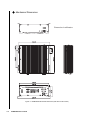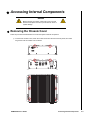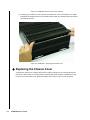
1
KUBE-8020 Fanless Box PC User’s Guide Rev. 2.00 May 1, 2008 Customer Service Contact Info: Quanmax Inc. 4F, No. 415, Ti-Ding Blvd. Sec. 2 NeiHu District, Taipei 114 Taiwan Tel: +886-2-2799-2789 Fax: +886-2-2799-7399 Visit our site at: www.quanmax.com © 2008 Quanmax Inc. All rights reserved. The information in this user’s guide is provided for reference only. Quanmax does not assume any liability arising out of the application or use of the information or products described herein. This user’s guide may contain or reference information and products protected by copyrights or patents and does not convey any license under the patent rights of Quanmax, nor the rights of others. Quanmax is a registered trademark of Quanmax. All trademarks, registered trademarks, and trade names used in this user’s guide are the property of their respective owners. All rights reserved. This user’s guide contains information proprietary to Quanmax. Customers may reprint and use this user’s guide in other publications. Customers may alter this user’s guide and publish it only after they remove the Quanmax name, cover, and logo. Quanmax reserves the right to make changes without notice in product or component design as warranted by evolution in user needs or progress in engineering or manufacturing technology. Changes which affect the operation of the unit will be documented in the next revision of this user’s guide. Revision 1.00 2.00 Date 01/24/2008 05/01/2008 Edited by JC JC Changes Initial Release Convert to Quanmax X Contents Safety Instructions Before You Begin. . . . . . . . . . . . . . . . . . . . . . . . . . . . . . . . . . . . . . . . . . . . . . . . . . . . . . . . . . . . xi When Working Inside a Computer. . . . . . . . . . . . . . . . . . . . . . . . . . . . . . . . . . . . . . . . . . . . . . xii Preventing Electrostatic Discharge . . . . . . . . . . . . . . . . . . . . . . . . . . . . . . . . . . . . . . . . . . . . . xiii Instructions for Lithium Battery . . . . . . . . . . . . . . . . . . . . . . . . . . . . . . . . . . . . . . . . . . . . . . . . xiv Voltage Ratings . . . . . . . . . . . . . . . . . . . . . . . . . . . . . . . . . . . . . . . . . . . . . . . . . . . . . . . . . . . . xiv Preface How to Use This Guide . . . . . . . . . . . . . . . . . . . . . . . . . . . . . . . . . . . . . . . . . . . . . . . . . . . . . . xvii Advisory Conventions . . . . . . . . . . . . . . . . . . . . . . . . . . . . . . . . . . . . . . . . . . . . . . . . . . . . . . xviii Unpacking . . . . . . . . . . . . . . . . . . . . . . . . . . . . . . . . . . . . . . . . . . . . . . . . . . . . . . . . . . . . . . . . xix Regulatory Compliance Statements . . . . . . . . . . . . . . . . . . . . . . . . . . . . . . . . . . . . . . . . . . . . xx Warranty Policy . . . . . . . . . . . . . . . . . . . . . . . . . . . . . . . . . . . . . . . . . . . . . . . . . . . . . . . . . . . . xxi Limited Warranty . . . . . . . . . . . . . . . . . . . . . . . . . . . . . . . . . . . . . . . . . . . . . . . . . . . . . . . xxi Return Procedure . . . . . . . . . . . . . . . . . . . . . . . . . . . . . . . . . . . . . . . . . . . . . . . . . . . . . . . xxi Limitation of Liability . . . . . . . . . . . . . . . . . . . . . . . . . . . . . . . . . . . . . . . . . . . . . . . . . . . . . xxi Maintaining Your Computer . . . . . . . . . . . . . . . . . . . . . . . . . . . . . . . . . . . . . . . . . . . . . . . . . . . xxii Environmental Factors . . . . . . . . . . . . . . . . . . . . . . . . . . . . . . . . . . . . . . . . . . . . . . . . . . . xxii Power Protection . . . . . . . . . . . . . . . . . . . . . . . . . . . . . . . . . . . . . . . . . . . . . . . . . . . . . . xxiii Chapter 1 Product Introduction Overview . . . . . . . . . . . . . . . . . . . . . . . . . . . . . . . . . . . . . . . . . . . . . . . . . . . . . . . . . . . . . . . . . 1-3 Checklist. . . . . . . . . . . . . . . . . . . . . . . . . . . . . . . . . . . . . . . . . . . . . . . . . . . . . . . . . . . . . . 1-4 Features . . . . . . . . . . . . . . . . . . . . . . . . . . . . . . . . . . . . . . . . . . . . . . . . . . . . . . . . . . . . . . 1-5 Product Specifications . . . . . . . . . . . . . . . . . . . . . . . . . . . . . . . . . . . . . . . . . . . . . . . . . . . . . . . 1-6 Mechanical Layout . . . . . . . . . . . . . . . . . . . . . . . . . . . . . . . . . . . . . . . . . . . . . . . . . . . . . . . . . 1-7 Front Panel. . . . . . . . . . . . . . . . . . . . . . . . . . . . . . . . . . . . . . . . . . . . . . . . . . . . . . . . . . . . 1-7 Rear Panel . . . . . . . . . . . . . . . . . . . . . . . . . . . . . . . . . . . . . . . . . . . . . . . . . . . . . . . . . . . . 1-7 Mechanical Dimensions . . . . . . . . . . . . . . . . . . . . . . . . . . . . . . . . . . . . . . . . . . . . . . . . . . 1-8 Chapter 2 Assembly/Disassembly Accessing Internal Components . . . . . . . . . . . . . . . . . . . . . . . . . . . . . . . . . . . . . . . . . . . . . . . 2-3 Removing the Chassis Cover. . . . . . . . . . . . . . . . . . . . . . . . . . . . . . . . . . . . . . . . . . . . . . 2-3 Replacing the Chassis Cover . . . . . . . . . . . . . . . . . . . . . . . . . . . . . . . . . . . . . . . . . . . . . . 2-4 System Component Locations . . . . . . . . . . . . . . . . . . . . . . . . . . . . . . . . . . . . . . . . . . . . . 2-5 Memory Module Installation. . . . . . . . . . . . . . . . . . . . . . . . . . . . . . . . . . . . . . . . . . . . . . . . . . . 2-6 Installing a DIMM . . . . . . . . . . . . . . . . . . . . . . . . . . . . . . . . . . . . . . . . . . . . . . . . . . . . . . . 2-6 Removing a DIMM: . . . . . . . . . . . . . . . . . . . . . . . . . . . . . . . . . . . . . . . . . . . . . . . . . . . . . 2-6 Installing a Mini PCI Card . . . . . . . . . . . . . . . . . . . . . . . . . . . . . . . . . . . . . . . . . . . . . . . . . . . . 2-7 Installing a Wi-Fi Antenna . . . . . . . . . . . . . . . . . . . . . . . . . . . . . . . . . . . . . . . . . . . . . . . . . . . . 2-7 Wall Mounting . . . . . . . . . . . . . . . . . . . . . . . . . . . . . . . . . . . . . . . . . . . . . . . . . . . . . . . . . . . . . 2-7 KUBE-8020 User’s Guide iii Chapter 3 Getting Started Power Connection. . . . . . . . . . . . . . . . . . . . . . . . . . . . . . . . . . . . . . . . . . . . . . . . . . . . . . . . . . DC Power . . . . . . . . . . . . . . . . . . . . . . . . . . . . . . . . . . . . . . . . . . . . . . . . . . . . . . . . . . . . AC Power. . . . . . . . . . . . . . . . . . . . . . . . . . . . . . . . . . . . . . . . . . . . . . . . . . . . . . . . . . . . . Operating System and Drivers . . . . . . . . . . . . . . . . . . . . . . . . . . . . . . . . . . . . . . . . . . . . . . . . Chipset Driver Installation . . . . . . . . . . . . . . . . . . . . . . . . . . . . . . . . . . . . . . . . . . . . . . . . . . . . Graphics Driver Installation . . . . . . . . . . . . . . . . . . . . . . . . . . . . . . . . . . . . . . . . . . . . . . . . . . . Audio Driver Installation . . . . . . . . . . . . . . . . . . . . . . . . . . . . . . . . . . . . . . . . . . . . . . . . . . . . . LAN Driver Installation . . . . . . . . . . . . . . . . . . . . . . . . . . . . . . . . . . . . . . . . . . . . . . . . . . . . . . 3-3 3-3 3-4 3-5 3-5 3-5 3-5 3-5 Chapter 4 Maintenance Maintenance and Prevention . . . . . . . . . . . . . . . . . . . . . . . . . . . . . . . . . . . . . . . . . . . . . . . . . 4-3 Chapter 5 Interfaces External Connectors . . . . . . . . . . . . . . . . . . . . . . . . . . . . . . . . . . . . . . . . . . . . . . . . . . . . . . . . Internal Connectors and Jumpers . . . . . . . . . . . . . . . . . . . . . . . . . . . . . . . . . . . . . . . . . . . . . . Jumper Settings . . . . . . . . . . . . . . . . . . . . . . . . . . . . . . . . . . . . . . . . . . . . . . . . . . . . . . . . Connector Pin Definitions . . . . . . . . . . . . . . . . . . . . . . . . . . . . . . . . . . . . . . . . . . . . . . . . iv KUBE-8020 User’s Guide 5-3 5-5 5-7 5-8 X Tables Table 1-1. KUBE-8020 Specifications . . . . . . . . . . . . . . . . . . . . . . . . . . . . . . . . . . . . . . . . . . . 1-6 Table 5-1. PS/2 Mouse Connector pin definition . . . . . . . . . . . . . . . . . . . . . . . . . . . . . . . . . . . 5-3 Table 5-2. PS/2 Keyboard Connector pin definition . . . . . . . . . . . . . . . . . . . . . . . . . . . . . . . . 5-3 Table 5-3. COM1 RS-232 Serial Port Connector pin definition . . . . . . . . . . . . . . . . . . . . . . . . 5-3 Table 5-4. VGA Display Connector pin definition . . . . . . . . . . . . . . . . . . . . . . . . . . . . . . . . . . 5-4 Table 5-5. RJ-45 + 2 USB 2.0 Connector pin definition . . . . . . . . . . . . . . . . . . . . . . . . . . . . . 5-4 Table 5-6. Jumper Descriptions. . . . . . . . . . . . . . . . . . . . . . . . . . . . . . . . . . . . . . . . . . . . . . . . 5-7 Table 5-7. Panel Power Selection - LVDS1. . . . . . . . . . . . . . . . . . . . . . . . . . . . . . . . . . . . . . . 5-7 Table 5-8. Panel Power Selection - LVDS2. . . . . . . . . . . . . . . . . . . . . . . . . . . . . . . . . . . . . . . 5-7 Table 5-9. Clear CMOS Setting. . . . . . . . . . . . . . . . . . . . . . . . . . . . . . . . . . . . . . . . . . . . . . . . 5-7 Table 5-10. Main Board Connector and Header Descriptions. . . . . . . . . . . . . . . . . . . . . . . . . 5-8 Table 5-11. ATX Power Connector pin definition . . . . . . . . . . . . . . . . . . . . . . . . . . . . . . . . . . 5-9 Table 5-12. Digital I/O Pin Header pin definition . . . . . . . . . . . . . . . . . . . . . . . . . . . . . . . . . . . 5-9 Table 5-13. CD-in Connector pin definition . . . . . . . . . . . . . . . . . . . . . . . . . . . . . . . . . . . . . . . 5-9 Table 5-14. IrDA Connector pin definition . . . . . . . . . . . . . . . . . . . . . . . . . . . . . . . . . . . . . . . 5-10 Table 5-15. TV Input Pin Header pin definition . . . . . . . . . . . . . . . . . . . . . . . . . . . . . . . . . . . 5-10 Table 5-16. Digital I/O Pin Header pin definition . . . . . . . . . . . . . . . . . . . . . . . . . . . . . . . . . . 5-10 Table 5-17. COM2-4 RS232 Serial Port Header pin definition . . . . . . . . . . . . . . . . . . . . . . . 5-11 Table 5-18. DVI+S/PDIF Pin Header pin definition . . . . . . . . . . . . . . . . . . . . . . . . . . . . . . . . 5-11 Table 5-19. DVI Pin Header pin definition . . . . . . . . . . . . . . . . . . . . . . . . . . . . . . . . . . . . . . . 5-11 Table 5-20. Fan Connectors pin definition. . . . . . . . . . . . . . . . . . . . . . . . . . . . . . . . . . . . . . . 5-12 Table 5-21. Floppy Connector pin definition . . . . . . . . . . . . . . . . . . . . . . . . . . . . . . . . . . . . . 5-12 Table 5-22. Front Panel 1 Header pin definition . . . . . . . . . . . . . . . . . . . . . . . . . . . . . . . . . . 5-12 Table 5-23. Front Panel 2 Header pin definition . . . . . . . . . . . . . . . . . . . . . . . . . . . . . . . . . . 5-13 Table 5-24. IDE1 Connector pin definition. . . . . . . . . . . . . . . . . . . . . . . . . . . . . . . . . . . . . . . 5-13 Table 5-25. LVDS1 Connector pin definition . . . . . . . . . . . . . . . . . . . . . . . . . . . . . . . . . . . . . 5-14 Table 5-26. LVDS2 Connector pin definition . . . . . . . . . . . . . . . . . . . . . . . . . . . . . . . . . . . . . 5-14 Table 5-27. Serial ATA Connector pin definition . . . . . . . . . . . . . . . . . . . . . . . . . . . . . . . . . . 5-15 Table 5-28. USB Header pin definition . . . . . . . . . . . . . . . . . . . . . . . . . . . . . . . . . . . . . . . . . 5-15 KUBE-8020 User’s Guide v vi KUBE-8020 User’s Guide X Figures Figure 1-1. KUBE-8020 Mechanical Layout - Front Panel . . . . . . . . . . . . . . . . . . . . . . . . . . . 1-7 Figure 1-2. KUBE-8020 Mechanical Layout - Rear Panel . . . . . . . . . . . . . . . . . . . . . . . . . . . . 1-7 Figure 1-3. KUBE-8020 Mechanical Dimensions (with wall mount bracket) . . . . . . . . . . . . . . 1-8 Figure 2-1. KUBE-8020 Chassis Cover screw locations . . . . . . . . . . . . . . . . . . . . . . . . . . . . . 2-3 Figure 2-2. KUBE-8020 - Removing the Chassis Cover . . . . . . . . . . . . . . . . . . . . . . . . . . . . . 2-4 Figure 2-3. KUBE-8020 - System Component Locations . . . . . . . . . . . . . . . . . . . . . . . . . . . . 2-5 Figure 2-4. DIMM Memory and 240-pin Socket. . . . . . . . . . . . . . . . . . . . . . . . . . . . . . . . . . . . 2-6 Figure 2-5. Memory Installation . . . . . . . . . . . . . . . . . . . . . . . . . . . . . . . . . . . . . . . . . . . . . . . . 2-6 Figure 2-6. Secure the wallmount L-brackets to the KUBE-8020 chassis. . . . . . . . . . . . . . . . 2-7 Figure 3-1. Tighten the terminal block compression clamps on the DC inlet. . . . . . . . . . . . . . 3-3 Figure 5-1. KUBE-8020 Internal Jumper and Connector Locations - Top Side . . . . . . . . . . . . 5-5 Figure 5-2. KUBE-8020 Internal Socket Locations - Bottom Side . . . . . . . . . . . . . . . . . . . . . . 5-6 KUBE-8020 User’s Guide vii viii KUBE-8020 User’s Guide X Safety Instructions Contents Before You Begin . . . . . . . . . . . . . . . . . . . . . . . . . . . . . . . . . . . . . . xi When Working Inside a Computer . . . . . . . . . . . . . . . . . . . . . . . . . xii Preventing Electrostatic Discharge . . . . . . . . . . . . . . . . . . . . . . . xiii Instructions for Lithium Battery . . . . . . . . . . . . . . . . . . . . . . . . . . xiv Voltage Ratings . . . . . . . . . . . . . . . . . . . . . . . . . . . . . . . . . . . . . . .xiv This page intentionally left blank. x KUBE-8020 User’s Guide X Before You Begin Before handling the KUBE-8020, read the instructions and safety guidelines on the following pages to prevent damage to the product and to ensure your own personal safety. Refer to the “Advisories” section in the Preface for advisory conventions used in this user’s guide, including the distinction between Warnings, Cautions, Important Notes, and Notes. Always use caution when handling/operating a computer. Only qualified, experienced, authorized electronics service personnel should access the interior of a computer. The power supplies produce high voltages and energy hazards, which can cause bodily harm. Use extreme caution when installing or removing components. Refer to the installation instructions in this user’s guide for precautions and procedures. If you have any questions, please contact Quanmax Post-Sales Technical Support. WARNING High voltages are present inside the chassis when the unit’s power cord is plugged into an electrical outlet. Turn off system power, turn off the power supply, and then disconnect the power cord from its source before removing the chassis cover. Turning off the system power switch does not remove power to components. KUBE-8020 User’s Guide Before You Begin -xi X When Working Inside a Computer Before taking covers off a computer, perform the following steps: 1) Turn off the computer and any peripherals. 2) Disconnect the computer and peripherals from their power sources or subsystems to prevent electric shock or system board damage. This does not apply when hot swapping parts. 3) Follow the guidelines provided in “Preventing Electrostatic Discharge” on the following page. 4) Disconnect any telephone or telecommunications lines from the computer. In addition, take note of these safety guidelines when appropriate: To help avoid possible damage to system boards, wait five seconds after turning off the computer before removing a component, removing a system board, or disconnecting a peripheral device from the computer. When you disconnect a cable, pull on its connector or on its strain-relief loop, not on the cable itself. Some cables have a connector with locking tabs. If you are disconnecting this type of cable, press in on the locking tabs before disconnecting the cable. As you pull connectors apart, keep them evenly aligned to avoid bending any connector pins. Also, before connecting a cable, make sure both connectors are correctly oriented and aligned. CAUTION Do not attempt to service the system yourself except as explained in this user’s guide. Follow installation and troubleshooting instructions closely. xii KUBE-8020 User’s Guide X Preventing Electrostatic Discharge Static electricity can harm system boards. Perform service at an ESD workstation and follow proper ESD procedure to reduce the risk of damage to components. Quanmax strongly encourages you to follow proper ESD procedure, which can include wrist straps and smocks, when servicing equipment. You can also take the following steps to prevent damage from electrostatic discharge (ESD): When unpacking a static-sensitive component from its shipping carton, do not remove the component’s antistatic packing material until you are ready to install the component in a computer. Just before unwrapping the antistatic packaging, be sure you are at an ESD workstation or grounded. This willl discharge any static electricity that may have built up in your body. When transporting a sensitive component, first place it in an antistatic container or packaging. Handle all sensitive components at an ESD workstation. If possible, use antistatic floor pads and workbench pads. Handle components and boards with care. Don’t touch the components or contacts on a board. Hold a board by its edges or by its metal mounting bracket. Do not handle or store system boards near strong electrostatic, electromagnetic, magnetic, or radioactive fields. KUBE-8020 User’s Guide Preventing Electrostatic Discharge -xiii X Instructions for Lithium Battery The installed SBC (Single Board Computer) of your KUBE-8020 is equipped with a lithium battery. WARNING Danger of explosion when battery is replaced with incorrect type. Only replace with the same or equivalent type recommended by the manufacturer. Do not dispose of lithium batteries in domestic waste. Dispose of the battery according to the local regulations dealing with the disposal of these special materials (e.g. to the collecting points for disposal of batteries). X Voltage Ratings The KUBE-8020 has the following voltage input ratings: DC 15-35V (5.5A @ 24VDC typical) optional AC adapter (100-240V, 1.3A@100V) xiv KUBE-8020 User’s Guide X Preface Contents How to Use This Guide . . . . . . . . . . . . . . . . . . . . . . . . . . . . . . . . xvii Unpacking . . . . . . . . . . . . . . . . . . . . . . . . . . . . . . . . . . . . . . . . . xviii Regulatory Compliance Statements. . . . . . . . . . . . . . . . . . . . . . . xix Warranty Policy . . . . . . . . . . . . . . . . . . . . . . . . . . . . . . . . . . . . . . . xx Limited Warranty. . . . . . . . . . . . . . . . . . . . . . . . . . . . . . . . . . . xx Return Procedure . . . . . . . . . . . . . . . . . . . . . . . . . . . . . . . . . . xx Limitation of Liability . . . . . . . . . . . . . . . . . . . . . . . . . . . . . . . . xx Maintaining Your Computer . . . . . . . . . . . . . . . . . . . . . . . . . . . . . xxi Environmental Factors . . . . . . . . . . . . . . . . . . . . . . . . . . . . . .xxi Power Protection . . . . . . . . . . . . . . . . . . . . . . . . . . . . . . . . . xxii This page intentionally left blank. xvi KUBE-8020 User’s Guide X How to Use This Guide This guide is designed to be used as step-by-step instructions for installation, and as a reference for operation, troubleshooting, and upgrades. Note: Driver downloads and additional information are available under Downloads on our web site: www.quanmax.com. The following is a summary of the chapter contents: Chapter 1, Product Introduction, presents the product specifications and system architecture for the KUBE-8020. Chapter 2, Assembly/Disassembly, describes how to access the system’s internal components and locations of connectors so that you can easily configure your system. Chapter 3, Getting Started, describes how to connect power to your system and installation of the required drivers and operating system. Chapter 4, Maintenance and Prevention, describes how to maintain your system and prevent damage and may include instructions for fan removal, cleaning the air filter and battery replacement. Chapter 5, Interface Definitions, provides information on the connector interfaces of the KUBE-8020. KUBE-8020 User’s Guide How to Use This Guide -xvii X Unpacking When unpacking, follow these steps: 1) After opening the box, save it and the packing material for possible future shipment. 2) Remove all items from the box. If any items listed on the purchase order are missing, notify Quanmax customer service immediately. 3) Inspect the product for damage. If there is damage, notify Quanmax customer service immediately. Refer to “Warranty Policy” for the return procedure. xviii KUBE-8020 User’s Guide X Regulatory Compliance Statements This section provides the FCC compliance statement for Class A devices. X FCC Compliance Statement for Class A Devices The product(s) described in this user’s guide has been tested and found to comply with the limits for a Class A digital device, pursuant to Part 15 of the FCC Rules. These limits are designed to provide reasonable protection against harmful interference when the equipment is operated in a commercial environment. This equipment generates, uses, and can radiate radio frequency energy and, if not installed and used in accordance with the user’s guide, may cause harmful interference to radio communications. Operation of this equipment in a residential area (domestic environment) is likely to cause harmful interference, in which case the user will be required to correct the interference (take adequate measures) at their own expense. Changes or modifications not expressly approved by Quanmax could void the user's authority to operate the equipment. Note: The assembler of a personal computer system may be required to test the system and/or make necessary modifications if a system is found to cause harmful interference or to be noncompliant with the appropriate standards for its intended use. KUBE-8020 User’s Guide Regulatory Compliance Statements -xix X X Warranty Policy Limited Warranty Quanmax Inc.’s detailed Limited Warranty policy can be found under Support at www.quanmax.com. Please consult your distributor for warranty verification. The limited warranty is void if the product has been subjected to alteration, neglect, misuse, or abuse; if any repairs have been attempted by anyone other than Quanmax or its authorized agent; or if the failure is caused by accident, acts of God, or other causes beyond the control of Quanmax or the manufacturer. Neglect, misuse, and abuse shall include any installation, operation, or maintenance of the product other than in accordance with the user’s guide. No agent, dealer, distributor, service company, or other party is authorized to change, modify, or extend the terms of this Limited Warranty in any manner whatsoever. Quanmax reserves the right to make changes or improvements in any product without incurring any obligation to similarly alter products previously purchased. X Return Procedure For any Limited Warranty return, please contact Support at www.quanmax.com and login to obtain a Return Material Authorization (RMA) Number. If you do not have an account, send an email to [email protected] to apply for one. All product(s) returned to Quanmax for service or credit must be accompanied by a Return Material Authorization (RMA) Number. Freight on all returned items must be prepaid by the customer who is responsible for any loss or damage caused by common carrier in transit. Returns for Warranty must include a Failure Report for each unit, by serial number(s), as well as a copy of the original invoice showing the date of purchase. To reduce risk of damage, returns of product must be in a Quanmax shipping container. If the original container has been lost or damaged, new shipping containers may be obtained from Quanmax Customer Service at a nominal cost. Quanmax owns all parts removed from repaired products. Quanmax uses new and reconditioned parts made by various manufacturers in performing warranty repairs and building replacement products. If Quanmax repairs or replaces a product, its warranty term is not extended. Shipments not in compliance with this Limited Warranty Return Policy will not be accepted by Quanmax. X Limitation of Liability In no event shall Quanmax be liable for any defect in hardware, software, loss, or inadequacy of data of any kind, or for any direct, indirect, incidental, or consequential damages in connection with or arising out of the performance or use of any product furnished hereunder. Quanmax’s liability shall in no event exceed the purchase price of the product purchased hereunder. The foregoing limitation of liability shall be equally applicable to any service provided by Quanmax or its authorized agent. xx KUBE-8020 User’s Guide X Maintaining Your Computer X Environmental Factors X Temperature The ambient temperature within an enclosure may be greater than room ambient temperature. Installation in an enclosure should be such that the amount of air flow required for safe operation is not compromised. Consideration should be given to the maximum rated ambient temperature. Overheating can cause a variety of problems, including premature aging and failure of chips or mechanical failure of devices. If the system has been exposed to abnormally cold temperatures, allow a two-hour warm-up period to bring it up to normal operating temperature before turning it on. Failure to do so may cause damage to internal components, particularly the hard disk drive. X Humidity High-humidity can cause moisture to enter and accumulate in the system. This moisture can cause corrosion of internal components and degrade such properties as electrical resistance and thermal conductivity. Extreme moisture buildup inside the system can result in electrical shorts, which can cause serious damage to the system. Buildings in which climate is controlled usually maintain an acceptable level of humidity for system equipment. However, if a system is located in an unusually humid location, a dehumidifier can be used to maintain the humidity within an acceptable range. Refer to the “Specifications” section of this user’s guide for the operating and storage humidity specifications. X Altitude Operating a system at a high altitude (low pressure) reduces the efficiency of the cooling fans to cool the system. This can cause electrical problems related to arcing and corona effects. This condition can also cause sealed components with internal pressure, such as electrolytic capacitors, to fail or perform at reduced efficiency. KUBE-8020 User’s Guide Maintaining Your Computer -xxi X Power Protection The greatest threats to a system’s supply of power are power loss, power spikes, and power surges caused by electrical storms, which interrupt system operation and/or damage system components. To protect your system, always properly ground power cables and one of the following devices. X Surge Protector Surge protectors are available in a variety of types and usually provide a level of protection proportional with the cost of the device. Surge protectors prevent voltage spikes from entering a system through the AC power cord. Surge protectors, however, do not offer protection against brownouts, which occur when the voltage drops more than 20 percent below the normal AC line voltage level. X Line Conditioner Line conditioners go beyond the overvoltage protection of surge protectors. Line conditioners keep a system’s AC power source voltage at a fairly constant level and, therefore, can handle brownouts. Because of this added protection, line conditioners cost more than surge protectors. However, line conditioners cannot protect against a complete loss of power. X Uninterruptible Power Supply Uninterruptible power supply (UPS) systems offer the most complete protection against variations on power because they use battery power to keep the server running when AC power is lost. The battery is charged by the AC power while it is available, so when AC power is lost, the battery can provide power to the system for a limited amount of time, depending on the UPS system. UPS systems range in price from a few hundred dollars to several thousand dollars, with the more expensive unit s allowing you to run larger systems for a longer period of time when AC power is lost. UPS systems that provide only 5 minutes of battery power let you conduct an orderly shutdown of the system, but are not intended to provide continued operation. Surge protectors should be used with all UPS systems, and the UPS system should be Underwriters Laboratories (UL) safety approved. xxii KUBE-8020 User’s Guide Chapter 1 X Product Introduction Contents Overview . . . . . . . . . . . . . . . . . . . . . . . . . . . . . . . . . . . . . . . . . . . Checklist . . . . . . . . . . . . . . . . . . . . . . . . . . . . . . . . . . . . . . . . Features . . . . . . . . . . . . . . . . . . . . . . . . . . . . . . . . . . . . . . . . Product Specifications . . . . . . . . . . . . . . . . . . . . . . . . . . . . . . . . . Mechanical Layout . . . . . . . . . . . . . . . . . . . . . . . . . . . . . . . . . . . . Front Panel . . . . . . . . . . . . . . . . . . . . . . . . . . . . . . . . . . . . . . Rear Panel . . . . . . . . . . . . . . . . . . . . . . . . . . . . . . . . . . . . . . Mechanical Dimensions . . . . . . . . . . . . . . . . . . . . . . . . . . . . 1-3 1-4 1-5 1-6 1-7 1-7 1-7 1-8 This page intentionally left blank. 1-2 KUBE-8020 User’s Guide X Overview The KUBE-8020 is a compact Fanless Box PC ideal for space-critical applications. This powerful embedded hardware platform supports an Intel® Core™2 Duo processor (Socket-M, 478-pin µFC-PGA package), 945GM/ICH7M chipset, and DDR2 up to 4GB . Featured are a 2.5” SATA HDD, and Mini PCI slot, dual Gigabit Ethernet, USB 2.0, VGA, optional DVI and HDMI, serial port, and PS/2 KB/MS. The KUBE-8020 provides high performance, reliability for harsh environments, compact size, noiseless operation and is highly suited to a wide range of industrial applications such as Kiosk, ATM, Gaming, Transportation, Entertainment, Surveillance, and Thin Servers. Wall and desktop mounting supported. KUBE-8020 User’s Guide Overview 1-3 X Checklist 1. Take out the KUBE-8020 series unit from the carton box, check if the unit is properly secure in the plastic bag. 2. Check the contents of the carton box: Box PC Wallmount Brackets (2 pcs.) Screw bag (6 pcs. for Wallmount Brackets) Driver CD AC adapter with power cord (optional) If any of these items is damaged or missing, please contact Quanmax. Save all packing materials for future replacement and maintenance. 1-4 KUBE-8020 User’s Guide X X Features Motherboard The KUBE-8020 is based on a Mini-ITX motherboard supporting a single Intel® Core™ 2 Duo Processor (Socket-M) in a 478 µFC-PGA package , Intel® 945GM GMCH and Intel® I/O Controller Hub 7 ICH7M chipset, 2x DIMM slots for 400/533/667 DDR2 up to 4GB, dual Gigabit Ethernet via two Realtek 8111B Controllers, LPC-based Winbond W83627EHF Super I/O controller, and Realtek ALC883 HD Audio CODEC. X Input/Output The KUBE-8020 has the following I/O interfaces: Front I/O: Power Switch Power LED HDD Activity LED 2x USB ports Rear I/O: 2x Gigabit Ethernet 1x Serial Port 4x USB 2.0 VGA port DVI-I, HDMI (optional, with UGM module) Mic-in, Line-in, Line-out (HD audio) PS/2 Keyboard, Mouse Wi-Fi antenna (optional) X Storage The KUBE-8020 has a 2.5” Hard Drive Bay (SATA). X Expansion The KUBE-8020 has a Mini PCI slot and UGM module interface. X Power Supply The KUBE-8020 has a DC 15-35V power supply (optional AC adapter). KUBE-8020 User’s Guide Overview 1-5 X Product Specifications KUBE-8020 Specifications Construction Processor Chipset RAM Internal Storage Front I/O Rear I/O Expansion Power Supply Cooling Temperature / Humidity Vibration Shock Dimensions Weight Mounting OS Certifications RoHS compliant • • • • • • • • • • • • • • • • • • • • • • • • • • • • • • • • • • SECC t=1.0mm chassis & aluminum extrusion Intel® Core™2 Duo support – Socket-M, 478-pin mFC-PGA Intel® 945GM GMCH, ICH7M 2x DIMM DDR2 400/533/667 dual channel up to 4 GB 1x 2.5” SATA HDD Power Switch Power LED HDD Activity LED 2x USB ports 2x Gigabit Ethernet 1x Serial Port 4x USB 2.0 VGA port DVI-I, HDMI (optional, with UGM module) Mic-in, Line-in, Line-out (HD audio) PS/2 Keyboard, Mouse WiFi antenna (optional) Mini PCI slot UGM module interface DC 15-35V (5.5A @ 24VDC typical) optional AC adapter (100-240V, 1.3A@100V) Fanless, integrated cooling solution Operating: 0°C to 50°C, 10%-90%, non-condensing Storage: -20°C to 80°C, 10%-90%, non-condensing Operating (IEC 68-2-64 Fh): 5-500Hz, 1 g (rms) / 3-axes Storage (IEC 68-2-6 Fc): 5-500Hz, 2 g (rms) / 3-axes Operating: 10 g / 11ms (half-sine) Storage: 50 g / 11ms (half-sine) 242.6 x 227.4 x 74.0 mm (WxDxH) 3.5kg (approx.) Desktop, Wall mount Windows 2000/2003, XP, Linux, XP embedded CE, FCC Class A yes Table 1-1. KUBE-8020 Specifications 1-6 KUBE-8020 User’s Guide X Mechanical Layout X Front Panel Power Switch USB Ports Power LED HDD LED Figure 1-1. KUBE-8020 Mechanical Layout - Front Panel X Rear Panel MS COM1 LAN HDMI* DVI* Wi-Fi Antenna* *optional KB VGA USB Audio DC in Figure 1-2. KUBE-8020 Mechanical Layout - Rear Panel KUBE-8020 User’s Guide Mechanical Layout 1-7 X Mechanical Dimensions Dimensions in millimeters Figure 1-3. KUBE-8020 Mechanical Dimensions (with wall mount bracket) 1-8 KUBE-8020 User’s Guide Chapter 2 X Assembly/Disassembly Contents Accessing Internal Components . . . . . . . . . . . . . . . . . . . . . . . . . Removing the Chassis Cover . . . . . . . . . . . . . . . . . . . . . . . . Replacing the Chassis Cover . . . . . . . . . . . . . . . . . . . . . . . . System Component Locations . . . . . . . . . . . . . . . . . . . . . . . Memory Module Installation . . . . . . . . . . . . . . . . . . . . . . . . . . . . . Installing a DIMM . . . . . . . . . . . . . . . . . . . . . . . . . . . . . . . . . Removing a DIMM: . . . . . . . . . . . . . . . . . . . . . . . . . . . . . . . . Installing a Mini PCI Card . . . . . . . . . . . . . . . . . . . . . . . . . . . . . . Installing a Wi-Fi Antenna . . . . . . . . . . . . . . . . . . . . . . . . . . . . . . Wall Mounting . . . . . . . . . . . . . . . . . . . . . . . . . . . . . . . . . . . . . . . 2-3 2-3 2-4 2-5 2-6 2-6 2-6 2-7 2-7 2-7 This page intentionally left blank. 2-2 KUBE-8020 User’s Guide X Accessing Internal Components WARNING Before opening your system, make sure to turn it off and disconnect the power sources to prevent electric shock or system damage. X Removing the Chassis Cover Follow the procedure described below to access the system's internal components. 1) To remove the chassis cover, loosen the 4 short screws from the front and rear panels, and and 6 long screws from the chassis cover as shown. KUBE-8020 User’s Guide Accessing Internal Components 2-3 Figure 2-1. KUBE-8020 Chassis Cover screw locations 2) Carefully pry the chassis cover up and off of the chassis base. Use a non-metallic tool or Phillips screwdriver tip wrapped in cloth if you have difficulty. Be careful not to damage the thermal pads on the underside of the lid. Figure 2-2. KUBE-8020 - Removing the Chassis Cover X Replacing the Chassis Cover To replace the chassis cover, carefully align it with the chassis, making sure not to damage the thermal pads. Ensure that all wires are correctly routed to avoid damaging them. Replace and tighten the 6 long screws to secure the chassis cover. Replace and tighten the 4 screws on the front and rear panels. 2-4 KUBE-8020 User’s Guide X System Component Locations See Figure 2-3 below for the locations of the internal components of the system. Front Panel Memory Slots Mini PCI Slot Hard Drive Bay Figure 2-3. KUBE-8020 - System Component Locations KUBE-8020 User’s Guide Accessing Internal Components 2-5 X Memory Module Installation Figure 3-4 below displays the notch marks as they should look on your DIMM memory modules. DDR2 DIMMs have 240-pins and one notch that will match with the onboard DIMM sockets. DIMM modules are installed by placing the chip firmly into the socket at a 90-degree angle and pressing straight down (Figure 3-4) until it fits tightly into the DIMM socket. Figure 2-4. DIMM Memory and 240-pin Socket X X Installing a DIMM Carefully follow the steps below in order to install the DIMMs: 1) To avoid generating static electricity and damaging the DIMM, ground yourself by touching a grounded metal surface or using a ground strap before you touch the DIMM. 2) Do not touch the connectors of the DIMM. Dirt or other residue may cause a malfunction. 3) Hold the DIMM with its notch aligned with the memory socket of the KUBE-8020 and insert it completely into the socket. Lift the locking tabs at each end of the DIMM socket to lock it in position. Figure 2-5. Memory Installation 4) If you install two DIMMs, install the second DIMM using the same procedure as above. 5) If the DIMM does not go in smoothly, do not force it. Pull it all the way out and try again. 6) Make sure the DIMM is properly installed and locked by the tabs on both sides of the socket. X Removing a DIMM: To remove the DIMM, use your fingers or a small screwdriver to carefully push away the plastic tabs that secure the DIMM at each end. Lift it out of the socket. Make sure you store the DIMM in an anti-static bag. The socket must be populated with memory modules of the same size and manufacturer. 2-6 KUBE-8020 User’s Guide X Installing a Mini PCI Card The KUBE-8020 provides space for one Mini PCI expansion card as shown in Figure 2-3 above. To install a Mini PCI card fully insert card into the slot, then press down to lock the card in place. X Installing a Wi-Fi Antenna The KUBE-8020 provides an opening to install a Wi-Fi antenna, shown in Figure 1-2. KUBE-8020 Mechanical Layout - Rear Panel. To install a Wi-Fi antenna, remove the circular pre-cut punch-out and secure the antenna to the chassis. X Wall Mounting The KUBE-8020 comes with two L-brackets for wall mounting. Secure the L-brackets to the chassis as shown using the screws provided. Figure 2-6. Secure the wallmount L-brackets to the KUBE-8020 chassis Refer to Figure 1-3. KUBE-8020 Mechanical Dimensions for wallmount hole spacing. The shape of the screw holes allows the KUBE-8020 to be mounted with the Front Panel facing either up or down, and provides for easy removal of the chassis for repair of maintanence. Use standard M4 or M5 screws to mount the KUBE8020. KUBE-8020 User’s Guide Installing a Mini PCI Card 2-7 This page intentionally left blank. 2-8 KUBE-8020 User’s Guide Chapter 3 X Getting Started Contents Power Connection . . . . . . . . . . . . . . . . . . . . . . . . . . . . . . . . . . . . DC Power . . . . . . . . . . . . . . . . . . . . . . . . . . . . . . . . . . . . . . . AC Power . . . . . . . . . . . . . . . . . . . . . . . . . . . . . . . . . . . . . . . Operating System and Drivers. . . . . . . . . . . . . . . . . . . . . . . . . . . Chipset Driver Installation . . . . . . . . . . . . . . . . . . . . . . . . . . . . . . Graphics Driver Installation . . . . . . . . . . . . . . . . . . . . . . . . . . . . . Audio Driver Installation . . . . . . . . . . . . . . . . . . . . . . . . . . . . . . . . LAN Driver Installation . . . . . . . . . . . . . . . . . . . . . . . . . . . . . . . . . 3-3 3-3 3-4 3-5 3-5 3-5 3-5 3-5 This page intentionally left blank. 3-2 KUBE-8020 User’s Guide X X Power Connection DC Power 1) Make sure the power distribution to the DC power feed wires is disconnected. 2) Remove just enough insulator material from the ends of the wires to allow a proper electrical connection to the terminal block. 3) Insert the power feed wires into the terminal block and tighten the compression clamps on the top side of the terminal block. tighten compression clamps Power Inlet Figure 3-1. Tighten the terminal block compression clamps on the DC inlet 4) Connect the power distribution to the DC power feed wires. KUBE-8020 User’s Guide Power Connection 3-3 X AC Power The KUBE-8020 has an optional external AC adapter. 1) Connect the output wires of AC adapter to the system DC power inlet as for the DC Power version above. Make sure note the correct polarity of the wires: White = positive (+), Black = negative (-). 2) Connect the other end of the AC power cord to a corresponding outlet. CAUTION Use the power cord suitable for the power supply in your country. Do not remove or alter the grounding prong on the power cord. In situations where a two-slot receptacle is present, have it replaced with a properly grounded three-prong grounding type receptacle. 3-4 KUBE-8020 User’s Guide X Operating System and Drivers If your KUBE-8020 Box PC does not come with an operating system pre-installed, you will need to install an operating system and the necessary drivers as described below. After you have finished assembling your system and connected the appropriate power source, power it up using the ATX Power Switch and install the desired operating system. The following sections describe driver installation procedures for Windows operating systems. Download the drivers for the KUBE-8020 Box PC from the Quanmax website at www.quanmax.com and install them in the order they are listed below. For other operating systems, please contact Quanmax. X Chipset Driver Installation To install the Intel® 855G chipset drivers, extract the contents of ICH_KUBE-8020.zip and run the file “infinst_autol.exe” in ICH Driver. When asked to reboot the system, click “yes”. X Graphics Driver Installation After installing the chipset driver, extract the contents of Graphics_KUBE-8020.zip and install the graphics driver by running the file “win2k_xp1429.exe”. After installation is complete, reboot the system. X Audio Driver Installation To install the install the audio driver, extract the contents of Audio_KUBE-8020.zip and run the file “WDM_R167.exe”. Follow the instructions given. X LAN Driver Installation To install the LAN Driver, extract the contents of LAN_KUBE-8020.zip and run the file “setup.exe” and follow the instructions given. KUBE-8020 User’s Guide Operating System and Drivers 3-5 This page intentionally left blank. 3-6 KUBE-8020 User’s Guide Chapter 4 X Maintenance Contents Maintenance and Prevention . . . . . . . . . . . . . . . . . . . . . . . . . . . . 4-3 This page intentionally left blank. 4-2 KUBE-8020 User’s Guide X Maintenance and Prevention Your KUBE-8020 system requires minimal maintenance and care to keep it operating correctly. Occasionally wipe the system with a soft dry cloth. You should only remove persistent dirt by use of a soft, slightly damp cloth (use only a mild detergent). Make sure the ventilation holes are clear of debris. KUBE-8020 User’s Guide Maintenance and Prevention 4-3 This page intentionally left blank. 4-4 KUBE-8020 User’s Guide Chapter 5 X Interfaces Contents External Connectors . . . . . . . . . . . . . . . . . . . . . . . . . . . . . . . . . . Internal Connectors and Jumpers . . . . . . . . . . . . . . . . . . . . . . . . Jumper Settings . . . . . . . . . . . . . . . . . . . . . . . . . . . . . . . . . . Connector Pin Definitions . . . . . . . . . . . . . . . . . . . . . . . . . . . 5-3 5-5 5-7 5-8 This page intentionally left blank. 5-2 KUBE-8020 User’s Guide X External Connectors Please refer to Figure 1-2. KUBE-8020 Mechanical Layout - Rear Panel for connector locations. X PS/2 Mouse Connector (CN7: 6-pin green Mini DIN): PIN SIGNAL PIN SIGNAL 1 3 5 Mouse data Ground Mouse clock 2 4 6 NC +5V NC Table 5-1. PS/2 Mouse Connector pin definition X PS/2 Keyboard Connector (CN7: 6-pin purple Mini DIN): PIN SIGNAL PIN SIGNAL 1 3 5 Keyboard data Ground Keyboard clock 2 4 6 NC +5V NC Table 5-2. PS/2 Keyboard Connector pin definition X COM1 RS-232 Serial Port Connector (CN9: D-Sub 9-pin male): PIN SIGNAL PIN SIGNAL 1 2 3 4 5 DCD (Data Carrier Detect) RXD (Receive Data) TXD (Transmit Data) DTR (Data Terminal Ready) Ground 6 7 8 9 DSR (Data Set Ready) RTS (Request to Send) CTS (Clear to Send) RI (Ring Indicator) Table 5-3. COM1 RS-232 Serial Port Connector pin definition KUBE-8020 User’s Guide External Connectors 5-3 X VGA Display Connector (CN9: D-Sub 15-pin female): PIN SIGNAL PIN SIGNAL 1 3 5 7 9 11 13 15 Red Blue Ground Ground VCC NC HSync DDCClk 2 4 6 8 10 12 14 Green NC Ground Ground Ground DDCData VSync Table 5-4. VGA Display Connector pin definition X RJ-45 + 2 USB 2.0 Connector (CN5-6): PIN SIGNAL PIN SIGNAL 1 2 3 4 5 6 7 8 MDI[0]+ MDI[0]MDI[1]+ MDI[1]MDI[2]+ MDI[2]MDI[3]+ MDI[3]- 9 10 11 12 13 14 15 16 +5VSB USB_AUSB_A+ GND +5VSB USB_BUSB_B+ GND LAN LED Yellow OFF / Green / Orange Function LINK / ACTIVE Speed 10 / Speed 100 / Speed 1000 Table 5-5. RJ-45 + 2 USB 2.0 Connector pin definition 5-4 KUBE-8020 User’s Guide X Internal Connectors and Jumpers For jumper and connector locations, please refer to the diagrams below. Figure 5-1. KUBE-8020 Internal Jumper and Connector Locations - Top Side KUBE-8020 User’s Guide Internal Connectors and Jumpers 5-5 Figure 5-2. KUBE-8020 Internal Socket Locations - Bottom Side 5-6 KUBE-8020 User’s Guide X Jumper Settings To ensure correct system configuration, the following section describes how to set the jumpers to enable/ disable or change functions. For jumper descriptions, please refer to the table below. Jumper Function JP1 JP2 JP3 LVDS1 Panel Power Selection LVDS2 Panel Power Selection Clear CMOS Jumper Table 5-6. Jumper Descriptions X LVDS1 Panel Power Selection (JP1: 3-pin 2.54mm pitch header): Function JP1 + 3.3 V (Default) +5V 1-2 Short 2-3 Short Table 5-7. Panel Power Selection - LVDS1 X LVDS2 Panel Power Selection (JP2: 3-pin 2.54mm pitch header): Function JP3 + 3.3 V (Default) +5V 1-2 Short 2-3 Short Table 5-8. Panel Power Selection - LVDS2 X Clear CMOS setting (JP3: 2-pin 2.54mm pitch header): Function JP2 Normal (Default) Clear CMOS Open Short 1 2 Table 5-9. Clear CMOS Setting KUBE-8020 User’s Guide Internal Connectors and Jumpers 5-7 X Connector Pin Definitions For Main Board connector and header descriptions, please refer to the table below. Connector ATX1 CN1 CN2 CN3 CN4 CN8 CN11 COM2-4 DVI1 DVI2 FAN1 FAN2 FDD1 FP1 FP2 IDE1 LVDS1 LVDS2 PCI1 SATA1 SATA2 USB1 USB2 Function ATX Power Connector Digital I/O Pin Header CD-In Connector IrDA Connector TV Input Pin Header Front Panel Audio Pin Header UGM Connector RS-232 COM2-4 Box Header Primary DVI Pin Header Secondary DVI Pin Header 4-Pin Fan Connector 3-Pin Fan Connector Slim Type Floppy Connector Front Panel 1 Pin Header Front Panel 2 Pin Header IDE 44-pin Connector Primary LVDS Connector Secondary LVDS Connector PCI slots Primary SATA Connector Secondary SATA Connector USB 2.0 x2 Pin Header USB 2.0 x2 Pin Header Table 5-10. Main Board Connector and Header Descriptions 5-8 KUBE-8020 User’s Guide X ATX Power Connector (ATX1: 12x2 pin female): PIN SIGNAL PIN SIGNAL 1 2 3 4 5 6 7 8 9 10 11 12 +3.3V +3.3V GND +5V GND +5V GND POWER OK +5VSB +12V +12V +3.3V 13 14 15 16 17 18 19 20 21 22 23 24 +3.3V -12V GND PS_ON GND GND GND -5V +5V +5V +5V GND Table 5-11. ATX Power Connector pin definition X Digital I/O Pin Header (CN1: 5x2-pin header 2.54mm pitch): PIN SIGNAL PIN SIGNAL 1 3 5 7 9 DO0 DO1 DO2 DO3 +5V 2 4 6 8 10 DI0 DI1 DI2 DI3 GND 1 2 3 4 5 6 7 8 9 10 Table 5-12. Digital I/O Pin Header pin definition X CD-in Connector (CN2: 4-pin 2.54mm pitch): PIN SIGNAL 1 2 3 4 CD_IN (R) CD_GND CD_GND CD_IN (L) 1 2 3 4 Table 5-13. CD-in Connector pin definition KUBE-8020 User’s Guide Internal Connectors and Jumpers 5-9 X IrDA Connector (CN3: 4-pin 2.54mm pitch): PIN SIGNAL 1 1 2 3 4 5 +5V Key IR_Rx GND IR_Tx 5 Table 5-14. IrDA Connector pin definition X TV Input Pin Header (CN4: 4-pin 2.54mm pitch): PIN SIGNAL 1 2 3 4 S-Video C GND S-Video Y GND 1 4 Note: For use with optional UGM only. Table 5-15. TV Input Pin Header pin definition X Front Audio Connector (CN8: 5x2-pin header 2.54mm pitch): PIN SIGNAL PIN SIGNAL 1 3 5 7 9 MIC2-L MIC2-R Line2-R FIO_Sense Line2-L 2 4 6 8 10 Audio GND ACZ_DET# MIC2_JD Key Line2_JD 1 2 9 10 Table 5-16. Digital I/O Pin Header pin definition X UGM Connector (CN11: AMP/TYCO as for COM Express): Refer to UGM Specification V1.0: http://www.universal-graphics-module.org/specs/specs.php 5-10 KUBE-8020 User’s Guide X RS232 Serial Port Header (COM2-4: 5x2 box header 2.54mm pitch): PIN SIGNAL PIN SIGNAL 1 3 5 7 9 DCD TXD GND RTS RI 2 4 6 8 10 RXD DTR DSR CTS NC 1 2 3 4 5 6 7 8 9 10 Table 5-17. COM2-4 RS232 Serial Port Header pin definition X DVI+S/PDIF Pin Header (DVI1: 10x2-pin 2.0mm pitch): PIN SIGNAL PIN SIGNAL 1 2 1 3 5 7 9 11 13 15 17 19 TMDS _TX0+ TMDS _TX0GND TMDS _TX2+ TMDS _TX2GND DDC_CLK DDC_DAT KEY / GND SPDIF_IN 2 4 6 8 10 12 14 16 18 20 TMDS _TX1+ TMDS _TX1GND TMDS _CLK+ TMDS _CLKGND HPDET VCC GND SPDIF_OUT 19 20 Note: For use with optional UGM only. Table 5-18. DVI+S/PDIF Pin Header pin definition X DVI Pin Header (DVI2: 9x2-pin 2.0mm pitch): PIN SIGNAL PIN SIGNAL 1 3 5 7 9 11 13 15 17 TMDS _TX0+ TMDS _TX0GND TMDS _TX2+ TMDS _TX2GND DDC_CLK DDC_DAT KEY 2 4 6 8 10 12 14 16 18 TMDS _TX1+ TMDS _TX1GND TMDS _CLK+ TMDS _CLKGND HPDET VCC GND 1 2 18 Note: For use with optional UGM only. Table 5-19. DVI Pin Header pin definition KUBE-8020 User’s Guide Internal Connectors and Jumpers 5-11 X Fan Connectors (Fan1-2: 3-pin Wafer 2.54mm pitch): PIN SIGNAL 1 2 3 GND +12V FAN_RPM 1 2 3 Table 5-20. Fan Connectors pin definition X Floppy Connector (FDD1: FPC-26 1.0mm pitch): PIN 1 3 5 7 9 11 13 15 17 19 21 23 25 SIGNAL +5V +5V +5V N.C N.C N.C #DRIVE DENSITY SEL(#DS0) GND GND GND GND GND GND PIN SIGNAL 2 4 6 8 10 12 14 16 18 20 22 24 26 #INDEX #DRIVE SELECT A(#DSA) #DISK CHANGE(#DSKCHG) N.C #MOTOR A On(#MOA) DIRECTION SELECT(#DIR) #STEP #WRITE DATA(#WD) #WRITE GATE(#WE) #TRACK0 #WRITE PROTECT(#WP) #READ DATA(#RDATA) #SIDE ONE SELECT(#HEAD) Table 5-21. Floppy Connector pin definition X Front Panel 1 Header(FP1: 4x2-pin 2.54mm pitch): PIN SIGNAL PIN SIGNAL Reset Switch (+) External Speaker (+) 1 2 Reset Switch (-) NC 3 4 IDE LED (+) Internal Speaker 5 6 IDE LED (-) External Speaker (-) 7 8 Pins 2, 8: External Speaker wire Pins 6-8 shorted: Internal Speaker Enable (default) Table 5-22. Front Panel 1 Header pin definition 5-12 KUBE-8020 User’s Guide X Front Panel 2Header (FP2: 5x2-pin 2.54mm pitch): PIN SIGNAL PIN SIGNAL 1 3 5 7 9 Power LED (+) NC Power LED (-) KeyBoard Lock (+) GND 2 4 6 8 10 Power On Button (+) Power On Button (-) NC I2C Bus SMB Data I2C Bus SMB Clock Table 5-23. Front Panel 2 Header pin definition X IDE Connector (IDE1: 22x2 box header 2.0mm pitch): PIN SIGNAL PIN SIGNAL 1 3 5 7 9 11 13 15 17 19 21 23 25 27 29 31 33 35 37 39 41 43 Reset IDE IDE Data 7 IDE Data 6 IDE Data 5 IDE Data 4 IDE Data 3 IDE Data 2 IDE Data 1 IDE Data 0 Ground DREQ0 IDEIOW# IDEIOR# IDEIORDY DACK0# IDEIRQ14 IDE Address 1 IDE Address 0 IDE Chip select 1# IDE activity +5V GND 2 4 6 8 10 12 14 16 18 20 22 24 26 28 30 32 34 36 38 40 42 44 GND IDE Data 8 IDE Data 9 IDE Data 10 IDE Data 11 IDE Data 12 IDE Data 13 IDE Data 14 IDE Data 15 NC GND GND GND CBSEL GND NC PDIAG# IDE Address 2 IDE Chip select 3# GND +5V NC 1 43 2 44 Table 5-24. IDE1 Connector pin definition KUBE-8020 User’s Guide Internal Connectors and Jumpers 5-13 X LVDS1 Connector (LVDS1: Hirose DF13-30DP 1.25mm): PIN SIGNAL PIN SIGNAL 2 4 6 8 10 12 14 16 18 20 22 24 26 28 30 Backlight Control Panel Power TxclkB# TxclkB GND TxoutB0# TxoutB0 TxoutB1# TxoutB1 TxoutB2# TxoutB2 TxoutB3# TxoutB3 GND I2C_Clock 1 3 5 7 9 11 13 15 17 19 21 23 25 27 29 Backlight Enable Panel Power TxclkA# TxclkA GND TxoutA0# TxoutA0 TxoutA1# TxoutA1 TxoutA2# TxoutA2 TxoutA3# TxoutA3 GND I2C_Data 2 1 30 29 Table 5-25. LVDS1 Connector pin definition X LVDS2 Connector (LVDS2: Hirose DF13-40DP 1.25mm): PIN SIGNAL PIN SIGNAL 2 4 6 8 10 12 14 16 18 20 22 24 26 28 30 32 34 36 38 40 Backlight Control Panel Power TxclkB# TxclkB GND TxoutB0# TxoutB0 TxoutB1# TxoutB1 TxoutB2# TxoutB2 TxoutB3# TxoutB3 GND I2C_Clock GND TxoutB4# TxoutB4 GND Panel Power 1 3 5 7 9 11 13 15 17 19 21 23 25 27 29 31 33 35 37 39 Backlight Enable Panel Power TxclkA# TxclkA GND TxoutA0# TxoutA0 TxoutA1# TxoutA1 TxoutA2# TxoutA2 TxoutA3# TxoutA3 GND I2C_Data GND TxoutA4# TxoutA4 GND Panel Power Table 5-26. LVDS2 Connector pin definition 5-14 KUBE-8020 User’s Guide X Serial ATA Connectors (SATA1-2: 7-pin "L" type): PIN SIGNAL PIN SIGNAL 1 3 5 7 GND SATA_TXN SATA_RXN GND 2 4 6 SATA_TXP GND SATA_RXP Table 5-27. Serial ATA Connector pin definition X USB Header (USB1-2: 5x2-pin header 2.54mm pitch): PIN SIGNAL PIN SIGNAL 1 3 5 7 9 +5V USBD2USBD2+ GND “key” 2 4 6 8 10 +5V USBD3USBD3+ GND GND 1 2 3 4 5 6 7 8 10 Table 5-28. USB Header pin definition KUBE-8020 User’s Guide Internal Connectors and Jumpers 5-15