1
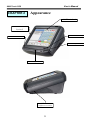
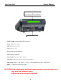
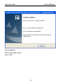
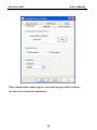
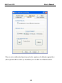
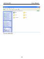
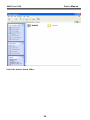
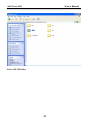
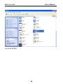
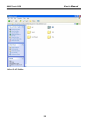
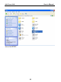
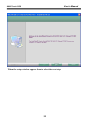
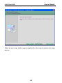
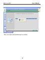
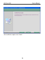
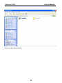
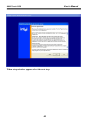
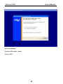
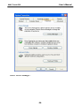
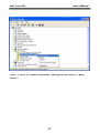
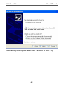
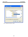
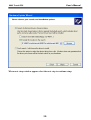
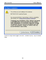
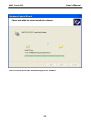
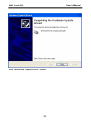
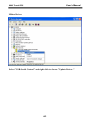
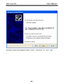
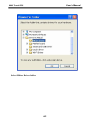
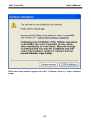
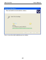
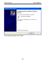
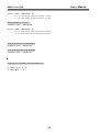
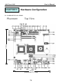
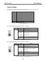
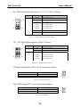
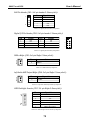
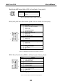
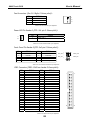
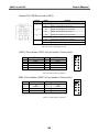
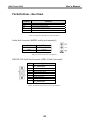
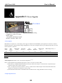
Touch POS System
SERIES 8802
Operation Manual
Version 1.0
User’s Manual
8802 Touch POS
Table of Contents:
Chapter 1 Specification introduction ........................................................................ 2
Chapter 2 Appearance ................................................................................................ 3
Chapter 3 Installation ................................................................................................. 5
Chapter 4 Commands for Peripheral Controlling .................................................. 70
Chapter 5 Hardware Configuration ........................................................................ 73
Chapter 6 Hardware Specification ........................................................................... 87
Appendix – Power supply .......................................................................................... 89
1
User’s Manual
8802 Touch POS
CHAPTER 1
Specification Introduction
Preview
The New Age of POS with its integrated TouchPOS. The 8802 is designed on NB base with Intel
Celeron M processor 1.5 GHz, One slot of DDR DIMM memory max up to 1GB; 12.1” TFT-LCD
with resistive touch screen; built-in VGA, LAN chip, Internal IDE Hard disk (20GB or above); includes
Magnetic card reader and 20X2 customer VFD display, XGA 1024 x 768 Resolution, wireless 802.11 b/g.
Thus designation helps user easy and comfortable to handling. Its multi-functional capability makes it
suitable for software developments under Windows XP, XP Embedded, XP professional for Embedded,
WIN 2000 professional Embedded, WIN NT 4.0, Linux, Redhat 7.2, WIN98, ME.
The brand new Touch POS 8802 has been designed with all advantages from POS series, but less cost
to customer with its interactive transaction, RFID and smart card reader design provides multiple
clerk access and customer database management, suitable and superior for super-market; hotel;
convenience store; restaurants and any organization or store that needs point of service.
Following description helps user understand what integrated part in 8802 TouchPOS.
Notes:
Must to adjust display setting in BIOS first.
Advanced Chipset Features
On-Chip VGA Setting
Boot Display [CRT+LCD]
Panel Type [1024x768 18Bit 1CH]
2
User’s Manual
8802 Touch POS
CHAPTER 2
Appearance
12.1" Touch Panel
IDE External Slots
(Optional)
LED Indicator
Power Button
RFID(Optional)
MSR(Optional)
LCD screen
brightness controls
3
User’s Manual
8802 Touch POS
20 x 2 VFD display (optional)
Or
WiFi wireless network (optional)
I/O Ports
COM1/COM2: Standard DB9 PIN Serial port
Mouse: PS2 mouse socket
K/B: PS2 Keyboard socket
USB: USB port X 2
VGA: 15 Pins VGA Connector
LAN: Ethernet connector
Multi-Media: Line Out / MIC / Line-In
CD1/CD2: Cash Draw 1(beside S/W) and Cash Draw 2
S/W: Switch button – S/W1 S/W2; ↓ = ON, ↑= OFF (Default S/W1=OFF , S/W2=OFF)
Power:
Connect to ATX power supply
CAUTION:While installing any additional hardware device, please make sure to
shut down the computer power.
(USB device is not subject to the limits.)
4
User’s Manual
8802 Touch POS
CHAPTER 3
Driver Installation
Touch Drivers
Insert CD Rom and select driver & manual folder.
5
User’s Manual
8802 Touch POS
Select Touch driver folder.
6
User’s Manual
8802 Touch POS
Access setup of 519d2166xp2k.exe
7
User’s Manual
8802 Touch POS
Skip out the previous setup screen and select next step.
8
User’s Manual
8802 Touch POS
After installation
System will require reboot
select “YES”
9
User’s Manual
8802 Touch POS
When first time complete Touch installation, require processing the cursor accuracy
calibration, Search for the Touchset utility shortcut on the desktop and select
Touchset utility to set up.
10
User’s Manual
8802 Touch POS
When configuration window appear, select the language which you desire
(As above selected picture explanation)
11
User’s Manual
8802 Touch POS
Than to select calibration function and select numbers of calibration point first
(above picture shows select by 4 numbers) next to click on calibrate button.
12
User’s Manual
8802 Touch POS
The screen will shows as above picture, use the Touch pen to point on dot to align the
cursor, if the actual alignment has too much difference than the system will skip back
to previous screen and require calibration once again.
13
User’s Manual
8802 Touch POS
The numbers of the calibration point shows on the screen will depend on the number
you have set previously, after complete system will skip back to desktop (if the cursor
still not accurate please repeat the calibration again).
14
User’s Manual
8802 Touch POS
IDE Drivers
Insert CD Rom and select driver & manual file folder.
15
User’s Manual
8802 Touch POS
Select the mother board folder.
16
User’s Manual
8802 Touch POS
And select IDE folder.
17
User’s Manual
8802 Touch POS
Access the infinst_autol.exe
18
User’s Manual
8802 Touch POS
When the setup screen appears than to select next step.
19
User’s Manual
8802 Touch POS
Select yes to accept authorization agreement.
20
User’s Manual
8802 Touch POS
Select next step to accept the software understanding agreement.
21
User’s Manual
8802 Touch POS
After installation
System will require reboot
select “YES”
22
User’s Manual
8802 Touch POS
And select IDE folder.
23
User’s Manual
8802 Touch POS
Select the mother board folder.
24
User’s Manual
8802 Touch POS
Select SOUND folder.
25
User’s Manual
8802 Touch POS
Access the SETUP.
26
User’s Manual
8802 Touch POS
When the setup screen appears click the next step.
27
User’s Manual
8802 Touch POS
Above screen shows the setup process.
28
User’s Manual
8802 Touch POS
After installation
System will require reboot
select “YES”
29
User’s Manual
8802 Touch POS
LAN Drivers
Select mother board folder.
30
User’s Manual
8802 Touch POS
Select LAN folder.
31
User’s Manual
8802 Touch POS
Access the SETUP.
32
User’s Manual
8802 Touch POS
When the setup window appear than to select the next step.
33
User’s Manual
8802 Touch POS
When the next setup window appears again select the setup to continue the setup
process.
34
User’s Manual
8802 Touch POS
Above screen shows the installation process window.
35
User’s Manual
8802 Touch POS
After installation complete select “finish”.
36
User’s Manual
8802 Touch POS
VGA Drivers
Insert CD Rom and select driver & manuals file folder.
37
User’s Manual
8802 Touch POS
Select mother board folder.
38
User’s Manual
8802 Touch POS
Select VGA folder.
39
User’s Manual
8802 Touch POS
Access win2k_xp141950.exe
40
User’s Manual
8802 Touch POS
When setup window appear select the next step.
41
User’s Manual
8802 Touch POS
When next setup window appear select the next step to continue setup.
42
User’s Manual
8802 Touch POS
When setup window appear select the next step.
43
User’s Manual
8802 Touch POS
After installation
System will require reboot
select “YES”
44
User’s Manual
8802 Touch POS
SmartCard Reader Driver
Right click "My Computer" and select the Properties.
45
User’s Manual
8802 Touch POS
Select "Device Manager".
46
User’s Manual
8802 Touch POS
Select "USB PC/SC SmartCard Reader" and right click to choose "Update
Driver.."
47
User’s Manual
8802 Touch POS
When the setup screen appears than to select "Advanced" & "Next" step.
48
User’s Manual
8802 Touch POS
Select "Smartcard USB Driver" folder.
49
User’s Manual
8802 Touch POS
When next setup window appear select the next step to continue setup.
50
User’s Manual
8802 Touch POS
When next setup window appear select the "Continue Anyway" step to continue
setup.
51
User’s Manual
8802 Touch POS
Above screen shows the installation process window.
52
User’s Manual
8802 Touch POS
After installation complete select “Finish”.
53
User’s Manual
8802 Touch POS
Wi-Fi Driver
Right click "My Computer" and select the Properties.
54
User’s Manual
8802 Touch POS
Select "Device Manager".
55
User’s Manual
8802 Touch POS
Select "USB2.0 WLAN" and right click to choose "Update Driver.."
56
User’s Manual
8802 Touch POS
When the setup screen appears than to select "Advanced" & "Next" step.
57
User’s Manual
8802 Touch POS
Select Wi-Fi Driver folder.
58
User’s Manual
8802 Touch POS
When next setup window appear select the next step to continue setup.
59
User’s Manual
8802 Touch POS
When next setup window appear select the "Continue Anyway" step to continue
setup.
60
User’s Manual
8802 Touch POS
Above screen shows the installation process window.
61
User’s Manual
8802 Touch POS
After installation complete select “Finish”.
62
User’s Manual
8802 Touch POS
Mifare Driver
Select "USB-Serial Control" and right click to choose "Update Driver.."
63
User’s Manual
8802 Touch POS
When the setup screen appears than to select "Advanced" & "Next" step.
64
User’s Manual
8802 Touch POS
Select Mifare Driver folder.
65
User’s Manual
8802 Touch POS
When next setup window appear select the next step to continue setup.
66
User’s Manual
8802 Touch POS
When next setup window appear select the "Continue Anyway" step to continue
setup.
67
User’s Manual
8802 Touch POS
Above screen shows the installation process window.
68
User’s Manual
8802 Touch POS
After installation complete select “Finish”.
69
User’s Manual
8802 Touch POS
CHAPTER 4
Commands for Peripheral Controlling
RS232 Protocol: 9600, N, 8, 1
Follow the standard command:
Send : <ESC> <Command code> <Length> <Data>
Response: <ESC> <Status code><length><data>
Note: 8802 controller return a beep after power on, delay about 3 sec then urn on the Main TFT Backlight, return another
beep and then start to receive the RS232 commands.
Read products Model Name
Command : <ESC><00h> Length & Data don’t need.
Response : <ESC><00h><07h><JP-8802>
Read Products Version info
Command : <ESC><01h> Length & Data don’t need.
Response: <ESC><01h> <Length depends on data ><8802 POS ……… V1.0 ….>
Beeps command:
Command : <ESC><22h> <01h><data>
<Data> = 00h ~ FFh , means how many beeps.
Response: <ESC><22h><01h><data>
Sound command:
Command : <ESC><24h> <02h><m><n>
m: tempo (ASCII DEC 1~255)
n: Frequency (ASCII DEC 1~255)
Response: <ESC><24h><02h><m><n>
Example:
<ESC><24h><02h><dec 2><dec 191> for play sound “Do“
Example Sound frequency Table:
70
User’s Manual
8802 Touch POS
Do
Re
Mi
Fa
So
La
Si
G- : 255
A- : 227
B- : 202
C : 191
D : 170
E : 151
F : 143
G : 127
A : 113
B : 101
C+: 95
D+: 85
E+: 75
F+: 71
G+: 63
A+: 57
B+: 50
Open Cash Drawer Command
:
Before send command, please confirm the SW1 for provides voltage:
SW1=OFF: 24V (default)
SW1=ON: 12V
The SW2 is for setting auto response cash drawer sensor status after trigger cash drawer, or if someone manually to
open the cash drawer or close the cash drawer
Then controller will auto response status to software application.
.
SW2=OFF: disable (default) SW2=ON: Enable
Open Cash Drawer 1
Command : <ESC> + 34h (dec 52)
When SW2=ON response: <ESC> + 34h (dec 52) + N
N = “A” (41h, dec 65) , means Cash Drawer 1 is close.
N = “B” (42h, dec 66) , means Cash Drawer 1 is open.
Open Cash Drawer 2
Command : <ESC> + 35h (dec 53)
When SW2=ON response: <ESC> + 35h (dec 53) + N
N = “A” (41h, dec 65), means Cash Drawer 2 is close.
N = “B” (42h, dec 66), means Cash Drawer 2 is open.
Detect Cash Drawer 1 Sensor
Command : <ESC> + 3Ah (dec 58)
71
User’s Manual
8802 Touch POS
Response: <ESC> + 34h (dec 52) + N
N = “A” (41h, dec 65) , means Cash Drawer 1 is close.
N = “B” (42h, dec 66) , means Cash Drawer 1 is open.
Detect Cash Drawer 2 Sensor
Command : <ESC> + 3Bh (dec 59)
Response: <ESC> + 35h (dec 53) + N
N = “A” (41h, dec 65), means Cash Drawer 2 is close.
N = “B” (42h, dec 66), means Cash Drawer 2 is open.
Turn on the main TFT LCD backlight
Command : <ESC> + 38h (dec 56)
Turn off the main TFT LCD backlight
Command : <ESC> + 39h (dec 57)
Support Epson command to open the cash drawer:
1.
2.
[ESC] p m t1 t2
DLE DC4 n m t
72
User’s Manual
8802 Touch POS
CHAPTER 5
Hardware Configuration
5-1. COMPONENT LOCATIONS
Placement
Top View
170mm
170mm
(Dimensions: +/- 1mm)
73
User’s Manual
8802 Touch POS
Bottom View
74
User’s Manual
8802 Touch POS
Jumper Settings
To ensure correct system configuration, the following section describes how to set the jumpers to enable/disable or
change functions. For jumper descriptions, please refer to the table below.
Location
Function
JP1
COM1 Signal / Power Selection
JP2
COM2 Signal / Power Selection
JP3
COM3 Signal / Power Selection
JP4
COM4 Signal / Power Selection
JP5
COM5 Signal / Power Selection
JP6
COM6 Signal / Power Selection
JP7
LPT1 Signal / Power Selection
JP8
JP9
CFD1 Master / Slave Selection
Clear CMOS Selection
JP10
LVDS Panel Power Selection
Table 2-1. Jumper Descriptions
JP1 - COM1 Signal/Power Selection (Pitch: 2.54mm):
Jumper
1
9
2
1
10
2
Setting
Function
1-3 Short
Pin 1 of COM1 = +12V
3-5 Short
Pin 1 of COM1 = +5V
5-7 Short
Pin 1 of COM1 = +5V
7-9 Short
Pin 1 of COM1 = DCD
2-4 Short
Pin 9 of COM1 = +12V
4-6 Short
Pin 9 of COM1 = +5V
6-8 Short
Pin 9 of COM1 = +5V
8-10 Short
Pin 9 of COM1 = RI
Table 2-2. JP1 - COM1 Signal/Power Selection Settings
JP2 - COM2 Signal/Power Selection (Pitch: 2.54mm):
Jumper
1
9
2
1
10
2
Setting
Function
1-3 Short
Pin 1 of COM2 = +12V
3-5 Short
Pin 1 of COM2 = +5V
5-7 Short
Pin 1 of COM2 = +5V
7-9 Short
Pin 1 of COM2 = DCD@RS232, TX+@RS422,
RTX+@RS485
2-4 Short
Pin 8 of COM1 = +12V
4-6 Short
Pin 8 of COM1 = +5V
6-8 Short
Pin 8 of COM1 = +5V
8-10 Short
Pin 8 of COM1 = RI
Table 2-3. JP1 - COM2 Signal/Power Selection Settings
75
User’s Manual
8802 Touch POS
JPx - COMx Signal/Power Selection (x = 3, 4, 5, 6 - Pitch: 2.54mm):
Jumper
1
9
2
Setting
1
10
2
Function
1-3 Short
Pin 1 of COMx = +12V
3-5 Short
Pin 1 of COMx = +5V
5-7 Short
Pin 1 of COMx = +5V
7-9 Short
Pin 1 of COMx = DCD
2-4 Short
Pin 8 of COMx = +12V
4-6 Short
Pin 8 of COMx = +5V
6-8 Short
Pin 8 of COMx = +5V
8-10 Short
Pin 8 of COMx = RI
Table 2-4. JP1 - COM3-6 Signal/Power Selection Settings
JP7 - LPT1 Signal/Power Selection (Pitch: 2.54mm):
Jumper
1
2
Setting
1
2
9
10
3
Function
1-2 Short
Pin 4 of LPT1 = ERR#
1-3 Short
Pin 4 of LPT1 = +5V
4-6 Short
Pin 6 of LPT1 = +5V
5-6 Short
Pin 6 of LPT1 = INIT#
7-8 Short
Pin 8 of LPT1 = SLIN#
7-9 Short
Pin 8 of LPT1 = +5V
Table 2-5. JP1 - LPT1 Signal/Power Selection
CF Master/Slave Selector (JP8: 3-pin 2.54mm pitch header):
Function
JP1
Master
Slave (Default)
1-2 Short
2-3 Short
Table 2-6. CF Master/Slave Setting
Clear CMOS setting (JP9: 2-pin 2.54mm pitch header):
Function
JP2
Normal (Default)
Clear CMOS
Open
Short
Table 2-7. Clear CMOS Setting
76
1
2
User’s Manual
8802 Touch POS
Panel Power Selector (JP10: 3-pin 2.54mm pitch header):
Function
JP3
+ 3.3 V (Default)
+5V
1-2 Short
2-3 Short
Table 2-8. Panel Power Setting
Connector Pin Definitions
For Main Board connector and header descriptions, please refer to the table below.
Connector
Function
ATX1
ATX Power Connector
CFD1
CN1
Compact Flash type I/II Connector
IrDA Pin Header
CN2
CN3
CN6
Digital Input / Digital Output Pin Header
SM Bus Wafer
Left Audio AMP Output Wafer
CN7
LVDS Backlight Inverter Wafer
CN8
COM2
COM3
Right Audio AMP Output Wafer
RS-232 / 422 / 485 Port-2 Box Header
RS-232 Port-3 Box Header
COM4
RS-232 Port-4 Box Header
COM5
COM6
DIMM1
RS-232 Port-5 Box Header
RS-232 Port-6 Box Header
Primary DDR SO-DIMM Socket
DIMM2
Secondary DDR SO-DIMM Socket
FAN1
FAN 1 Connector
FAN2
FAN3
FAN 2 Connector
FAN 3 Connector
FDD1
Slim Type Floppy Connector
FP1
Power LED Pin Header
FP2
IDE1
IDE2
Front Panel Pin Header
Primary 44-pin IDE Box Header
Secondary 40-pin IDE Box Header
KB1
Internal PS/2 Keyboard Wafer
LVDS1
LVDS2
MPCI1
Channel 1 LVDS Connector
Channel 2 LVDS Connector
Mini-PCI Socket
MS1
Internal PS/2 Mouse Wafer
SW1
USB1
USB2
External PS/2 KB/MS Switch
USB Port-2&3 Box Header
USB Port-4&5 Box Header
Table 2-9. Main Board Connector and Header Descriptions
77
User’s Manual
8802 Touch POS
ATX Power Connector (ATX1: 10x2 pin female):
PIN
SIGNAL
PIN
SIGNAL
1
2
3
4
5
6
7
8
9
10
+3.3V
+3.3V
Ground
+5V
Ground
+5V
Ground
PW-OK
5VSB
+12V
11
12
13
14
15
16
17
18
19
20
+3.3V
-12V
Ground
PS-ON
Ground
Ground
Ground
-5V
+5V
+5V
Table 2-10. ATX Power Connector pin definition
CompactFlash slot (CFD1):
PIN
SIGNAL
PIN
SIGNAL
1
3
5
7
9
11
13
15
17
19
21
23
25
27
29
31
33
35
37
39
41
43
45
47
49
GND
D4
D6
CS0#
ATASEL#
A8
VCC
A5
A3
A1
D0
D2
CD2
D11
D13
D15
VS1
IOWR#
INTRQ
CSEL#
RESSET#
INPACK#
DASP#
D8
D10
2
4
6
8
10
12
14
16
18
20
22
24
26
28
30
32
34
36
38
40
42
44
46
48
50
D3
D5
D7
A10
A9
A7
A6
A4
A2
A0
D1
IOCS16#
CD1
D12
D14
CS1#
IORD#
WE#
VCC
VS2#
IORDY
REG#
PDIAG#
D9
GND
Table 2-11. CompactFlash Slot pin definition
78
User’s Manual
8802 Touch POS
IrDA Pin Header (CN1: 5x2-pin header 2.54mm pitch):
1
Pin
Signal Name
1
+5V
2
3
4
5
NC
IRRX
GND
IRTX
5
Table 2-12. Digital I/O Pin Header pin definition
Digital I/O Pin Header (CN2: 5x2-pin header 2.54mm pitch):
PIN
SIGNAL
PIN
SIGNAL
1
3
5
7
9
DO0
DO1
DO2
DO3
+5V
2
4
6
8
10
DI0
DI1
DI2
DI3
GND
1
2
3
4
5
6
7
8
9
10
Table 2-13. Digital I/O Pin Header pin definition
SMBus Wafer (CN3: 2x1-pin Wafer 2.0mm pitch):
Pin
Status
1
2
SMDAT
SMCLK
Table 2-14. SMBus Header pin definition
Left Audio AMP Output Wafer (CN6: 2x1-pin Wafer 2.5mm pitch):
Pin
Signal Name
1
2
Speaker+
Speaker-
Table 2-15. Left Audio AMP Output Header pin definition
LVDS Backlight Inverter (CN7: 7x1-pin Wafer 2.0mm pitch):
Pin
Signal Name
1
2
3
4
5
6
7
+12V
+12V
+5V
GND
GND
Black Light Enable
Back Light Control
Table 2-16. LVDS Backlight Inverter Header pin definition
79
User’s Manual
8802 Touch POS
Right Audio AMP Output Wafer (CN8: 2x1-pin Wafer 2.5mm pitch):
Pin
1
2
Signal Name
Speaker+
Speaker-
Table 2-17. Right Audio AMP Output Header pin definition
RS232/422/485 Serial Port Header (COM2: 5x2 box header 2.54mm pitch):
Pin
1
2
3
1
2
4
5
9
10
6
7
8
9
10
Signal
+5V / +12V /
RS-232:DCD, Data carrier detect
RS-422:TX+
RS-485:RTX+
Note:Selected by JP2
DSR, Data set ready
RS-232:RXD, Receive data
RS-422:RX+
RS-485:N/A
RTS, Request to send
RS-232:TXD, Transmit data
RS-422:TXRS-485:RTXCTS, Clear to send
RS-232:DTR, Data terminal ready
RS-422:RXRS-485:N/A
+5V / +12V / RI, Ring indicator
Note:Selected by JP2
GND, ground
NC
Table 2-18. COM2 RS232/422/485 Serial Port Header pin definition
RS232 Serial Port Header (COM3-6: 5x2 box header 2.54mm pitch):
Pin
1
2
10
2
3
4
5
6
7
8
9
10
Signal
+5V / +12V / DCD, Data carrier detect
Note:Selected by JPx
DSR, Data set ready
RXD, Receive data
RTS, Request to send
TXD, Transmit data
CTS, Clear to send
DTR, Data terminal ready
+5V / +12V / RI, Ring indicator
Note:Selected by JPx
GND, ground
NC
(x = 3, 4, 5, 6)
Table 2-19. COM3-6 RS232 Serial Port Header pin definition
80
User’s Manual
8802 Touch POS
Fan Connectors (Fan1-3: Wafer 2.54mm pitch):
PIN
SIGNAL
1
2
3
RPM
+12V
GDN
1
2
3
Table 2-20. Fan Connectors pin definition
Power LED Pin Header 1 (FP1: 2x1-pin 2.54mm pitch):
Pin
1
2
Status
1
Power LED +
2
Power LED Table 2-21. Power LED Pin Header 1 pin definition
Front Panel Pin Header 2(FP2: 5x2-pin 2.54mm pitch):
PIN
SIGNAL
PIN
SIGNAL
1
3
5
7
9
HDD LED +
HDD LED Reset Swatch Reset Swatch +
NC
2
4
6
8
10
Power LED +
Power LED Power Switch +
Power Switch Key
HDD_LE D
RS T_S W
+
1
2 +
-
-
-
+
+
9
P WR_LE D
P WR_S W
10
Table 2-22. Front Panel Pin Header 2 pin definition
IDE1 Connector (IDE1: 22x2 box header 2.0mm pitch):
PIN
SIGNAL
PIN
SIGNAL
1
3
5
7
9
11
13
15
17
19
21
23
25
27
29
31
33
35
37
39
41
43
Reset IDE
IDE Data 7
IDE Data 6
IDE Data 5
IDE Data 4
IDE Data 3
IDE Data 2
IDE Data 1
IDE Data 0
Ground
DREQ0
IDEIOW#
IDEIOR#
IDEIORDY
DACK0#
IDEIRQ14
IDE Address 1
IDE Address 0
IDE Chip select 1#
IDE activity
+5V
GND
2
4
6
8
10
12
14
16
18
20
22
24
26
28
30
32
34
36
38
40
42
44
GND
IDE Data 8
IDE Data 9
IDE Data 10
IDE Data 11
IDE Data 12
IDE Data 13
IDE Data 14
IDE Data 15
NC
GND
GND
GND
CBSEL
GND
NC
PDIAG#
IDE Address 2
IDE Chip select 3#
GND
+5V
NC
Table 2-23. IDE1 Connector pin definition
81
1
43
2
44
User’s Manual
8802 Touch POS
IDE2 Connector (IDE2: 20x2 box header 2.54mm pitch):
PIN
SIGNAL
PIN
SIGNAL
1
3
5
7
9
11
13
15
17
19
21
23
25
27
29
31
33
35
37
39
IDE RESET
DATA7
DATA6
DATA5
DATA4
DATA3
DATA2
DATA1
DATA0
GND
REQ
IO WRITE
IO READ
IO READY
DACK
IRQ14
ADDR1
ADDR0
CS#1
LED
2
4
6
8
10
12
14
16
18
20
22
24
26
28
30
32
34
36
38
40
GND
DATA8
DATA9
DATA10
DATA11
DATA12
DATA13
DATA14
DATA15
N.C
GND
GND
GND
GND
GND
N.C
UDMA DETECT
ADDR2
CS#3
GND
Table 2-24. IDE2 Connector pin definition
Internal PS/2 KB (KB1: Wafer 2.5mm pitch):
Pin
Signal Name
1
+12V
2
+5V
3
KBCLK_SIO
4
KBDAT_SIO
5
KBCLK_PS2
6
KBDAT_PS2
7
GND
Table 2-25. Internal KB Wafer pin definition
82
User’s Manual
8802 Touch POS
Parallel Port Box Header (LPT1: 2.54mm):
Pin
2
1
3
5
7
25
26
9
11
13
15
17
19
21
23
25
Signal
Pin
Strob#, Line printer strobe
Signal
2
4
PD0, parallel data 0
AutoFeed
Error / +5V
Note:Selected by JP7
Initialize / +5V
Note:Selected by JP7
Select In / +5V
Note:Selected by JP7
GND
GND
GND
GND
GND
GND
GND
GND
NC
6
PD1, parallel data 1
8
PD2, parallel data 2
PD3, parallel data 3
PD4, parallel data 4
PD5, parallel data 5
PD6, parallel data 6
PD7, parallel data 7
ACK, acknowledge
Busy
Paper empty
Select
10
12
14
16
18
20
22
24
26
Table 2-26. Parallel Port pin definition
LVDS1-2 Channel 1-2 Connector (LVDS1-2: Hirose DF13 1.25mm):
Signal Name
+3.3V / +5V
Note:Selected by JP10
+3.3V / +5V
Note:Selected by JP10
LVDS_TX0LVDS_TX0+
GND
LVDS_TX1LVDS_TX1+
GND
LVDS_TX2LVDS_TX2+
Pin
Pin
1
2
3
4
5
7
9
11
13
15
17
19
6
8
10
12
14
16
18
20
Signal Name
+3.3V / +5V
Note:Selected by JP10
+3.3V / +5V
Note:Selected by JP10
LVDS_TX3LVDS_TX3+
GND
LVDS_CLKLVDS_CLK+
GND
GND
GND
Table 2-27. LVDS1-2 Connector pin definition
Internal PS/2 Mouse (MS1: Wafer 2.5mm pitch):
Pin
Signal Name
1
+5V
2
MSCLK_SIO
3
MSDAT_SIO
4
MSCLK_PS2
5
MSDAT_PS2
6
GND
Table 2-28. Internal Mouse Wafer pin definition
83
User’s Manual
8802 Touch POS
External PS/2 KB/Mouse Switch (SW1):
Switch
1
2
3
4
Status
Function
ON
KBCLK_SIO and KBCLK_PS2 are shorted.
OFF
KBCLK_SIO and KBCLK_PS2 are open.
ON
KBDAT_SIO and KBDAT_PS2 are shorted.
OFF
KBDAT_SIO and KBDAT_PS2 are open.
ON
MSCLK_SIO and MSCLK_PS2 are shorted.
OFF
MSCLK_SIO and MSCLK_PS2 are open.
ON
MSDAT_SIO and MSDAT_PS2 are shorted.
OFF
MSDAT_SIO and MSDAT_PS2 are open.
Table 2-29. External PS/2 KB/Mouse switch
USB2-3 Ports Header (USB1: 5x2-pin header 2.54mm pitch):
PIN
SIGNAL
PIN
SIGNAL
1
3
5
7
9
+5V
USBD2USBD2+
GND
“key”
2
4
6
8
10
+5V
USBD3USBD3+
GND
GND
1
2
3
4
5
6
7
8
10
Table 2-30. USB1 Header pin definition
USB4-5 Ports Header (USB2: 5x2-pin header 2.54mm pitch):
PIN
SIGNAL
PIN
SIGNAL
1
3
5
7
9
+5V
USBD4USBD4+
GND
“key”
2
4
6
8
10
+5V
USBD5USBD5+
GND
GND
Table 2-31. USB2 Header pin definition
84
1
2
3
4
5
6
7
8
10
User’s Manual
8802 Touch POS
Pin Definitions - Rear Panel
Location
Function
AUDIO1
Audio Phone Jack
COM1
RS-232 Port-1 DB9 Connector
CN9
RJ-45 + USB Port-0&1 Connector
CN11
Mini-DIN PS/2 KB/MS Connector
VGA1
CRT DB-15 Connector
Table 2-32. KEOD-4014 Rear Panel Connector Descriptions
Audio Jack Connector (AUDIO1: audio jack connector):
COLOR
SIGNAL
Blue
Green
Pink
Line-in
Line- out
MIC-in
Table 2-33. Audio Jack Connector pin definition
COM1 RS-232 Serial Port Connector (COM1: D-Sub 9-pin male):
Pin
1
2
3
4
5
6
7
8
9
Signal
+5V / +12V / DCD, Data carrier detect
Note:Selected by JP1
RXD, Receive data
TXD, Transmit data
DTR, Data terminal ready
GND, ground
DSR, Data set ready
RTS, Request to send
CTS, Clear to send
+5V / +12V / RI, Ring indicator
Note:Selected by JP1
Table 2-34. COM1 RS-232 Serial Port Connector pin definition
85
User’s Manual
8802 Touch POS
PS/2 Mouse Connector (CN11: 6-pin green Mini DIN):
PIN
SIGNAL
PIN
SIGNAL
1
3
5
Mouse data
Ground
Mouse clock
2
4
6
NC
+5V
NC
Table 2-35. PS/2 Mouse Connector pin definition
PS/2 Keyboard Connector (CN11: 6-pin purple Mini DIN):
PIN
SIGNAL
PIN
SIGNAL
1
3
5
Keyboard data
Ground
Keyboard clock
2
4
6
NC
+5V
NC
Table 2-36. PS/2 Keyboard Connector pin definition
VGA Display Connector (VGA1: D-Sub 15-pin female):
PIN
SIGNAL
PIN
SIGNAL
1
3
5
7
9
11
13
15
Red
Blue
Ground
Ground
VCC
NC
HSync
DDCClk
2
4
6
8
10
12
14
Green
NC
Ground
Ground
Ground
DDCData
VSync
Table 2-37. VGA Display Connector pin definition
RJ-45 + 2 USB0-1 Connector (CN9):
PIN
SIGNAL
PIN
SIGNAL
1
2
3
4
5
6
7
8
Transmit output (+)
Transmit output (-)
Receive input (+)
NC
NC
Receive input (-)
NC
NC
9
10
11
12
13
14
15
16
+5V
USB1USB1+
GND
+5V
USB2USB2+
GND
Table 2-38. RJ-45 + 2 USB 2.0 Connector pin definition
86
User’s Manual
8802 Touch POS
CHAPTER 6
Hardware Specification
Motherboard
CPU
System Memory
Chipset
Intel® Celeron® M Processor 1.5GHz
2 x DDR 266MHz SODIMMs, maximum 2GB
Intel® 852GM Graphic Memory Controller Hub
Intel® I/O Controller Hub 4 (ICH4)
Network
Audio
BIOS
Expansion
852GM GMCH internal ; VGA controllerCRT 2048x1536x8bit@60Hz
2 channels LVDS ; Dual Display ; Shared Memory up to 64MB
10/100 Base-T Ethernet RTL8100C
6-Channel AC’97 Audio CODEC ALC655 ; Stereo 2W Power Amplifier LM4838
Award PnP 4Mb Flash with console redirection
Mini-PCI Socket x 1
HDD
Flash Memory
Internal 1 x 3.5" HDD (20G or above) or Internal 2 x 2.5" HDD
Compact Flash (Type I & II)
LCD
Max. Resolution
Brightness
Touch Screen
12.1” TFT
1024 x 768
250 ~350cd/m²
Resistive
USB
Serial
Parallel
LAN
Keyboard
Mouse
2nd VGA Output
Audio Jack
Cash Drawer
6 x USB 2.0 ports for future expansion (2* Internal, 4*External)
2x User available Com ports (Com 1&Com 2)。
1 x Bi-directional Parallel Port Support ECP/EPP (IEEE 1284)
1 x RJ-45 Interface(10/100 Base-T Ethernet)
1 x PS/2 keyboard port
1 x PS/2 mouse port
VFD Customer Display (20 x 2)
MIC-in, Line-out, Line-in
2 x RJ11 Single/Dual Cashdrawer port(with 12V output.)
Graphics
Storage
Display
External I/O Ports
Power
Power Supply
Power Consumption
Power management
ATX 80W, Input 100V~240V to output 5V/12V power supply
60-80W Idle
(Standard system & secondary LCD panel while accessing HDD).
I/O peripheral devices support power saving management
Integrated Options
IDE Peripheral
Smart Card Reader
Magnetic Stripe Reader
Wireless LAN
1 x External IDE Device
1 x Built-In Smart Card Reader, compatible with Microsoft PC/SC (USB Interface)
1 x Build-In Magnetic Stripe Reader (PS2/KB) : ISO Standard ( up to 3 tracks)
Wi-Fi IEEE 802.11b/g
Power Button
Power Led
HDD Led
1
1
1
Control/ Indicator
87
User’s Manual
8802 Touch POS
Physical Dimensions
Dimension
(W)x(L)x(H)cm
Weight
Color
Physical: 27.5(W) x 29.5(L) x 13.5 (H)cm
Pagage: 34(W) x 53(L) x 53 (H)cm
N.W: 6 kgs
G.W: 7 Kgs
Dark Gray or White
Environment
Operating Temperature 0℃~ 45℃ (32℉ ~ 113℉)
Storage Temperature -20℃~ 60℃ (-4℉~ 140℉)
Operating Humidity
0% ~ 80% RH non condensing Storage Humidity
10% ~ 90% RH non condensing
Certification
EMC & Safety
FCC, CE, RoHS, Class B
OS support
Windows XP, XP Embedded, XP Professional for Embedded, WIN 2000 Professional
Embedded, WIN NT 4.0, Redhat 7.2, WIN 98/ME, Linux
Operation Systems
88
User’s Manual
8802 Touch POS
Appendix I: Power Supplely
FEATURES
80W with 8.6CFM forced air- cooling, 60W convection cooling
Compact size with ATX output
PG/PF Signal
+5V Stand by & Remote On/Off
MTBF>130,000 hr. MIL-217F.
1. Description
MPI-806H is a compact size, ATX output power supply for industrial and embedded system application. The device utilizes a
thermally efficient U channel chassis design. Designed to be convection cooling but however provided with optional cover and
fan for customers’ reference.
Output
Voltage
Mini.
Output
Current
Rated Output
Current
Max output
Current (Note 1)
Line
Regulation
Load
Regulation
Ripple & Noise
p-p (Note 2)
+5V
+12V
-12V
+3.3V
+5Vsb
1A
0A
0A
0A
0A
5A
1.5A
0.5A
4A
0.75A
8A
3A
1%
1%
1%
1%
1%
2%
4%
5%
4%
4%
50mV
120mV
120mV
50mV
120mV
6A
Initial Setting Accuracy (Note 3)
5.08V to 5.13V
11.4V to 12.6V
-11.4V to -12.6V
3.10V to 3.50V
4.80V to 5.20V
(Note 4)
Total Output Power: 80W at 50°C environment temperature
.
Note: 1) The maximum total combined output power on the +3.3V and +5V rails is 40W.
2) Measured by a 20MHz bandwidth limited oscilloscope and the each output is connected with a 10µF Electrolytic
Capacitor and a 0.1µF Ceramic Capacitor.
3) The +5V output is set between 5.08V to 5.13V by variable resistor and all output at 60% rated load and the other
Outputs are checked to be within the accuracy range. .
4) Total maximum load cannot exceed 80W with 8.6 CFM forced air-cooling and 60W convection cooling.
2. Input Specification
89
User’s Manual
8802 Touch POS
Parameter
Conditions/Description
Input Voltage-AC Continuous input range.
Input Frequency AC input.
Hold Up Time
Nominal AC Input Voltage (230VAC), rated load.
Input Current
Nominal AC Input Voltage (115VAC/230VAC), rated load.
Inrush Current
Nominal AC Input Voltage (115VAC/230VAC), one cycle at 25°C.
Input Protect
Non-user serviceable internally located AC input line fuse.
Min. Nom. Max. Units
90 115/230 264 VAC
47
63
Hz
20
ms
2/1
A
30/60 A
3. Output Specification
Parameter
Conditions/Description
Mi
n.
Efficiency
Rated load, 115VAC. Varies with distribution of loads among output.
Minimum load
Ripple & Noise Rated load, 20MHz bandwidth
Output Power
Continuous output power.
Line Regulation Less than ±1% at rated load with ±10% changing in input voltage.
Load Regulation
Measured from 60% to 100% rated load and from 60% to 20%
rated load (60% ±40% rated load) for each output, and others
Voltage setting at 60%.
Turn-on Delay Time required for initial output voltage stabilization
Nom. Max.
Units
70
See Chart of Description
See Chart of Description
See Chart of Description
See Chart of Description
%
See Chart of Description
0.3
4
Sec
4. Interface Signals and Internal Protection
Parameter
Conditions/Description
Power On/Off
The power supply will be turned on when the power On/Off pin is connected to secondary GND
Power Good Signal When power is turned on, the power good signal will go high 100ms to 500ms after all output DC
Voltages are within regulation limits.
Power Fail Signal The power fail signal will go low at least 1 mS before any of the output voltages fall below the regulation
Limits.
Over Load Protection Fully protected against output overload and short circuit. Automatic recovery upon of overload condition.
5. Safety Approvals, EMI and EMS Specification
Parameter
Safety Approvals
Hi-Pot
Hold Up Time
Conditions/Description
UL, UL 60950, 3rd edition
CB, IEC 60950-1
TUV, EN 60950-1: 2001
Input to output
Nominal AC Input Voltage (230VAC), rated load.
90
Min.
Nom.
Max.
Units
Approved
4242
20
VDC
mS
User’s Manual
8802 Touch POS
Radiation
Conduction
EMS
EN 55022 / CISPR 22 & FCC Part 15
EN 55022 / CISPR 22 & FCC Part 15
IEC 61000-4-2, 8KV air discharge and 6KV contact discharge
IEC 61000-4-3, 3V/M
IEC 61000-4-4, 2KV line & PE
IEC 61000-4-5, 2KV
IEC 61000-4-6, 10V
IEC 61000-4-8, 10A/M
IEC 61000-4-11
91
B
B
3
2
3
3
3
3
Class
Level