1
Eagle 450
Installation and
Technical Manual
DSM-00216-00
© 1998 ALPHA MICROSYSTEMS
FIRST EDITION: October 1998
To re-order this document, request part number DSO-00216-00.
FCC Notice
This equipment has been tested and found to comply with the limits for a Class A digital device, pursuant to Part 15 of the FCC
Rules. These limits are designed to provide reasonable protection against harmful interference when the equipment is operated in a
commercial environment. This equipment generates, uses and can radiate radio frequency energy and, if not installed and used in
accordance with the instruction manual, may cause harmful interference to radio communications. Operation of this equipment in a
residential area is likely to cause harmful interference in which case the user will be required to correct the interference at his own
expense.
Canadian Department of Communications Compliance Statement
This equipment does not exceed Class A limits per radio noise emissions for digital apparatus set out in the Radio Interference
Regulations of the Canadian Department of Communications. Operation in a residential area may cause unacceptable interference
to radio and TV reception requiring the owner or operator to take whatever steps are necessary to correct the interference.
Avis de Conformité aux Normes du Ministère des Communications du Canada
Cet équipment ne deapsse pas les limits de Classe A d'émission de bruits radioélectriques pour les appareils numeriques tels que
prescrites par le Règlement sur le brouillage radioélectrique établi par le ministère des Communications du Canada. L'exploitation
faite en milleu résidential peut entrainer le brouillage des réceptions radio et tele, ce qui obligerait le propriétaire ou l'opératour à
pendre les dispositions nécessaires pour en éliminer les causes.
Battery Warning
CAUTION: Danger of explosion if battery is incorrectly replaced. Replace only with the same or equivalent type recommended by
the manufacturer. Discard used batteries according to the manufacturer's instructions.
ATTENTION: Il y a danger d'explosion s'il y a replacement incorrect de la batterie. Remplacer uniquement avec une batterie du
même type ou d'un type recommandé par le constructeur. Mettre au rébut les batteries usagées conformément aux instructions du
fabricant.
For AM-3500-E100, -E200, -E300, -E400, -E500 and AM-990-01 systems replace battery with Panasonic or Ray-O-Vac BR2325
only. For AM-3500-E550, AM-3500-6000, and AM-990-04 systems, replace batteries with Panasonic or Ray-O-Vac BR1225 only.
Use of other batteries may present a risk of fire or explosion. Replacement batteries may be ordered from your authorized Alpha
Micro reseller.
Safety Warning
This computer contains no user-configurable components that require opening the computer case. Because the power supply in
this computer is capable of outputting high current levels hazardous to your safety, the computer case should only be opened by an
authorized service technician.
Cet ordinateur ne contient aucune pièce configurable par l’utilisateur qui nécessite l’ouverture du boitier. L’alimentation de cet
ordinateur peut preduire des nivaeux de tensions dangereux, le boitier ne devrait donc être ouvert que par un technician autoriaé.
SOFTWARE SECURITY DEVICE IDENTIFICATION NUMBER: _________________
The Alpha Micro Software Security Device (SSD) is a customized integrated circuit that personalizes the computer, providing
identity verification for it. Certain Alpha Micro and non-Alpha Micro software may require that your computer contain an SSD in
order to run software that has been customized to run only on your computer.
Please enter the identification of your SSD above. The SSD identification number should be on your computer ID label under "SSD
Serial No." (Another way of finding the number is to look at the SSD itself. The SSD is located in an integrated circuit location on
the CPU board; its identification number is printed on the SSD itself.) Software vendors may ask you for the SSD number if they are
customizing software to run only on your computer.
This document may contain references to products covered under the following U.S. Patent Number(s): 4,530,048
ALPHA MICROSYSTEMS
2722 Fairview Street
P. O. Box 25059
Santa Ana, CA 92704
Table of Contents
CHAPTER 1 - INTRODUCTION
THE EAGLE 450 DOCUMENTATION SET
Graphic Conventions
CHAPTER 2 - SPECIFICATIONS
GENERAL SPECIFICATIONS
REAR PANEL CONNECTIONS
AM-138 CENTRAL PROCESSING UNIT
STORAGE AND BACKUP
Fast-Wide SCSI (Small Computer System Interface) Bus
Narrow SCSI Bus
Hard Disk Drives
Streaming Tape Drives
Diskette Drive
SERIAL I/O
AM-318-10 Serial I/O Board
PARALLEL I/O
CHAPTER 3 - CONFIGURATION
THE EAGLE 450 BACK PANEL
SCSI CONFIGURATION
SCSI Device Types
Wide SCSI Configuration Rules
Narrow SCSI Configuration Rules
SERIAL I/O CONFIGURATION
Serial I/O Boards Supported
Signal Pinouts
Cabling Packages
PARALLEL I/O SUPPORT
NETWORK CONFIGURATION
10BaseT Cabling
EAGLE 450 UPS STATUS PORT
Eagle 450 Installation and Technical Manual, Rev. 00
1-1
1-1
1-2
2-1
2-1
2-2
2-2
2-3
2-3
2-3
2-3
2-4
2-4
2-5
2-5
2-6
3-1
3-1
3-3
3-3
3-3
3-5
3-6
3-6
3-7
3-8
3-14
3-15
3-15
3-15
Page ii
Table of Contents
CHAPTER 4 - INSTALLATION
4-1
SITE REQUIREMENTS
UNPACKING AND PREPARING THE EAGLE 450
Checking the AC Voltage Setting
Recording the SSD Identification Number
INITIAL SETUP AND TESTING
MODIFYING THE CMOS SETTINGS
Eagle 450 Initialization Routine
CMOS Menu Options
Saving the CMOS Settings
Important Note
MODIFYING THE INITIALIZATION FILE
Defining the Parallel Port
Defining Ports and Jobs
AlphaTCP Setup
Changing User Memory
SCSI Dispatcher Options
Setting Write Buffering
Disabling Super I/O
Multiple Initialization Files
ADDING USER NAMES
CHAPTER 5 - TROUBLESHOOTING
5-1
FRONT PANEL STATUS DISPLAY CODES
5-2
APPENDIX A - READ-AHEAD AND WRITE BUFFERING
READ-AHEAD
Controlling Read-Ahead
WRITE BUFFERING
Potential Pitfalls
Setting Up Write Buffering
FINAL NOTES
APPENDIX B - SUPER I/O
DISABLING SUPER I/O
Disabling Super I/O on All I/O Boards
Disabling Super I/O on Individual Boards
4-1
4-2
4-2
4-2
4-3
4-3
4-4
4-4
4-6
4-6
4-6
4-8
4-9
4-11
4-11
4-12
4-13
4-13
4-14
4-14
A-1
A-1
A-1
A-2
A-3
A-3
A-4
B-1
B-1
B-1
B-2
INDEX
Eagle 450 Installation and Technical Manual, Rev. 00
Chapter 1 - Introduction
This manual is for Alpha Microsystems dealers and technical personnel: people who will sell, install, and
maintain Eagle 450 computers. It does not contain material which the average end-user needs to know,
and, in general, does not need to be given to the end-user.
This book makes some assumptions about you, the reader:
• You are familiar with today’s computer terminology: you know what terms such as serial I/O,
Ethernet, and disk cache mean.
• You have used AMOS before, and have at least some knowledge of the operating system and of
previous Alpha Micro products. For example, you do not need to be told what the system
initialization command file is.
In addition to this introduction, which describes this book and the other Eagle 450 documentation, this
manual includes:
• Chapter 2 - Specifications: information which was contained in a separate specifications
document for previous systems: size and weight, electrical requirements, processor capabilities,
and so on.
• Chapter 3 - Configuration: guidelines for designing an Eagle 450: what I/O boards you can
use, how many SCSI devices you can hook up, etc.
• Chapter 4 - Installation: site requirements, CMOS and initialization file configuration, and
other installation procedures.
• Chapter 5 - Troubleshooting: status display codes and troubleshooting information.
• Appendix A - Read-ahead and Write Buffering: what they are and how to use them to
optimize system performance.
• Appendix B - Super I/O: how to turn off this performance-enhancing feature if necessary.
THE EAGLE 450 DOCUMENTATION SET
The complete documentation package for the Eagle 450 computer consists of three manuals, each
containing a different type of information and aimed at a different audience:
• The Eagle 450 Owner’s Manual: for the end-user, it contains non-technical information about
getting started with AMOS, how to care for the computer, and what to do if something goes
wrong. We recommend that you give this manual to the end user; it will answer many of their
questions, and it does not include technical information.
• The Eagle 450 Installation and Technical Manual (this book): for the dealer, with technical
specifications and configuration information and installation instructions. We do not suggest you
forward this book to the customer.
• The Eagle 450 Service Manual: for qualified service personnel only: opening the chassis,
installing new devices and changing board jumper settings.
Eagle 450 Installation and Technical Manual, Rev. 00
Page 1-2
Chapter One
Graphic Conventions
Like other Alpha Micro documents, this manual uses some standard symbols and special typefaces to
make our examples and explanations easier to read and understand:
Symbol
Description
This means STOP!, and signals an important warning or
restriction. Be sure to read the text next to this symbol
carefully, as it could help you avoid serious problems.
This marks a hint—a shortcut or an easier way to do
something.
This indicates a note: information which relates to the
current topic, and may be important for you to remember.
Text
We show characters the computer displays on your screen,
such as prompts and information messages, in this typeface.
We also use it for command file examples.
TEXT
In examples, we use this typeface for the characters you
type on your keyboard.
This symbol tells you to press the indicated key. For
example: DIR ENTER tells you to press the ENTER key at
the end of the DIR command.
KEY
CTRL
/C
This combination of symbols tells you to hold down the
first key and press the second key. For example, to type a
CTRL /C (Control-C), press the CTRL key and, while holding
it down, type a C.
Eagle 450 Installation and Technical Manual, Rev. 00
Chapter 2 - Specifications
GENERAL SPECIFICATIONS
Temperature/Humidity
Temperature: 60° to 90° F (15.6° to 32.2° C); 10° C per hour
maximum fluctuation;
Humidity: 20% to 80%, non-condensing
Power Requirements
USA and Canada: 115 VAC (90 to 132 VAC), 47 to 63Hz
International: 230 VAC (180 to 264 VAC), 47 to 63Hz
Maximum AC Power Consumption
AM-138 board: 5 amps at 115 volts or 2.5 amps at 230 volts
Note: due to varying peripherals, it is impossible to determine
total power requirements for complete system.
Maximum DC Power Requirements
+5 volts: 4.3A with 256MB DRAM; 3.9A with 8MB DRAM
+12 volts: less than 100mA
Figures for AM-138 board only
Electromagnetic Interference
Complies with US FCC rules and regulations, Class A
System Dimensions
Height:
Width:
Depth:
Weight:
Enclosure Composition
Sheet metal and plastic
Additional Features
Clock/calendar with battery backup
Front panel with status and diagnostic display
32-bit, bus-master RISC SCSI controller
Programmable interval timer
AC power failure detect
Remote reset option
Security lock
CMOS setup feature
Dedicated UPS monitoring port
Optional AM-338 RJE interface
17.75” (44.5 cm)
9” (22.9 cm)
17” (43.1 cm)
Up to 26 lb. (12 kg)
Eagle 450 Installation and Technical Manual, Rev. 00
Page 2-2
Chapter Two
REAR PANEL CONNECTIONS
Serial Ports
Eight standard, with full modem control and lightning protection
Up to 32 possible using AM-318-10 serial I/O boards (see
below)
Also accepts AM-314 and AM-318-00 boards.
Parallel Port
One 25-pin (see below)
Ethernet Port
10BaseT and AUI ports provided
External SCSI Port
Narrow or Wide, for external bus termination or external
devices
UPS Monitoring Port
9-pin
AM-138 CENTRAL PROCESSING UNIT
Processor
Motorola MCF5102 Coldfire CPU with variable-length RISC
CPU Speed
33MHz
Data/Address Path
Multiplexed 32-bit data/address path
Internal Cache
2KB instruction cache
External Cache
64KB unified instruction and data with burst support
Memory Expansion
Two SIMM slots; from 4MB to 256MB; can install either one or
two SIMMs
Interrupt Capabilities
Seven interrupt levels with vector capability
Direct Memory Access
Bus mastering capability, supports multiple masters
Ethernet
32-bit dual-port controller
SCSI Controller
32-bit bus-master RISC processor
PCI Interface
Two slots for industry-standard PCI cards. Not supported in
initial release.
Eagle 450 Installation and Technical Manual, Rev. 00
Specifications
Page 2-3
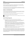
STORAGE AND BACKUP
Fast-Wide SCSI (Small Computer System Interface) Bus
Physical interface
68-pin connector
Maximum Bus Length
Ten feet (three meters)
Maximum Number of Devices
Up to five internal; multiple external devices (eight feet of
cable) possible using AM-441 Wide SCSI Bus Repeater
Protocol Supported
Full SCSI-1, SCSI-2 and Fast/Wide-SCSI supported, including
support for connect and disconnect protocols
Implementation
Single host only; multiple host architecture not supported
Narrow SCSI Bus
Physical Interface
50-pin connector
Maximum Bus Length
20 feet (six meters)
Maximum Number of Devices
Eight unique SCSI addresses, including the host controller
Protocol Supported
Full SCSI-1 and SCSI-2 supported, including support for
connect and disconnect protocols
Implementation
Single host only; multiple host architecture not supported
The two busses (SCSI and Wide-SCSI) are mutually exclusive. All devices must connect to one of
the two busses; the other connector cannot be used. Using the appropriate adapters, you can
connect a mix of SCSI-2 drives and Wide SCSI-2 drives to either SCSI bus.
Hard Disk Drives
Alpha Micro offers a complete line of narrow and wide SCSI disk drives, including external RAID
subsystems. See the current AMOS Hardware price list for the drives available.
Physical Size
3.5” or 5.25”
Maximum Number
Internal: five half-height; two can be either 3.5” or 5.25”; others
must be 3.5”; more may be added externally, depending on bus
limitations
Interface
SCSI or Wide SCSI
Eagle 450 Installation and Technical Manual, Rev. 00
Page 2-4
Chapter Two
Streaming Tape Drives
Physical Size
5.25” half-high
Interface
SCSI or Wide SCSI
Data Capacity
150MB to 26GB
Tape Cartridge
See Eagle 450 Computer Owner’s Manual
Tape Format
See Eagle 450 Computer Owner’s Manual
Soft Error Rate
1 x 10
Hard Error Rate
1 x 10
-8
-10
Diskette Drive
Physical Size
3.5”, but requires 5.25” mounting bay
Interface
SCSI; AM-219 Floppy Controller is not used
Data Capacity
1.44MB or 720KB depending on the format.
Diskettes
3.5” 18 sectors/track, 80 tracks/side, double-sided, doubledensity
Transfer Rate
500K bits/second.
Latency (Average)
100 msec.
Access Time
Track-to-track: 3 msec.
Average: 94 msec.
Track Density
135 TPI.
Recording Density
17,434 bits/inch.
MTBF
10,000 power on hours or more, normal duty cycle.
Error Rates
Soft read: 1 x 10⁻⁹
Hard read: 1 x 10-12
Seek: 1 x 10⁻⁴
Eagle 450 Installation and Technical Manual, Rev. 00
Specifications
Page 2-5
SERIAL I/O
Standard
Eight ports, with flow control and lightning protection
Characteristics
All asynchronous serial communication ports configured for
RS232. RS422 is not supported.
Interface
8-wire RJ-45 jacks standard. For pin signals see Chapter 3.
Supported Baud Rates
50, 75, 110, 134.5, 150, 300, 600, 1200, 1800, 2000, 2400, 3600,
4800, 7200, 9600, 19200, 38400, 57600
Stop Bits
2 stop bits if 110 baud;
1 stop bit all others—default.
Word Length
Default: 8 data bits
Parity
Default: No parity
Expansion
Three expansion slots for up to 32 ports total, using AM-318-10
boards
AM-318-10 Serial I/O Board
Number of ports
Eight per board; total of up to 24, with flow control and
lightning protection
Characteristics
All asynchronous serial communication ports configured for
RS232. RS422 is not supported.
Interface
8-wire RJ-45 jacks standard. For pinout diagram, see Chapter 3.
Supported Baud Rates
50, 75, 110, 134.5, 150, 300, 600, 1200, 1800, 2000, 2400, 3600,
4800, 7200, 9600, 19200, 38400, 57600
Stop Bits
2 stop bits if 110 baud;
1 stop bit all others—default
Word Length
Default: 8 data bits
Parity
Default: No parity
For compatibility with earlier systems, the Eagle 450 also supports 4-port AM-314 and 8-port
AM-318-00 serial I/O boards, with or without AM-90 cards for lightning protection.
Eagle 450 Installation and Technical Manual, Rev. 00
Page 2-6
Chapter Two
PARALLEL I/O
Number of Ports
One
Characteristics
Centronics compatible
Interface
DB-25 Connector; for DB-25 connector signals, see Chapter 3
Cable length
Parallel printer cable should not exceed six feet
Eagle 450 Installation and Technical Manual, Rev. 00
Chapter 3 - Configuration
This chapter discusses configuration rules, considerations, and procedures for the Eagle 450. It covers:
• Back panel connectors
• Wide and narrow SCSI configuration
• Serial and parallel I/O, including cabling information
• Networking
• UPS status port
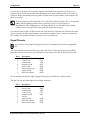
THE EAGLE 450 BACK PANEL
The illustration on the next page shows the Eagle 450 back panel, with the usable connectors labeled.
Refer to that drawing for the location of these connections:
• Each serial I/O expansion slot will accept an AM-90 board, which provides four RJ-45
connectors (standard for the eight on-board serial ports and the AM-318-10), an RJ-21 Telco
connector from an AM-318-00, or, with an adapter, two DB-9 connectors from an AM-314. If
you choose to use DB-9 connectors for compatibility with earlier hardware, your total port
capacity is reduced, as only two ports fit in each slot instead of four.
• You can use only one of the two Ethernet ports: either the RJ-45 10BaseT connection or the 15pin AUI connection. You cannot use both ports simultaneously to attach the Eagle 450 to two
networks.
• The external SCSI connector may be either a Wide SCSI-2 68-pin or a SCSI-2 50-pin connector,
depending on the SCSI bus you’ve chosen.
• The two PCI connectors are covered in the initial versions of the Eagle 450. Support for PCI
devices is planned for a future release.
These notes refer only to the types of connections you may see on the back panel; for more information
on SCSI, serial, and parallel I/O, and network connections, please refer to the appropriate sections later
in this chapter.
This back panel is used for factory-shipped Eagle 450s. Systems field-upgraded to an Eagle 450
have a different back panel, as shown in PDI-03500-21, Upgrade Instructions, AM-1600 or
Eagle100/300/500 to Eagle 450.
Eagle 450 Installation and Technical Manual, Rev. 00
Page 3-2
Chapter Three
0
SCSI
115
NOTE: You can
use either Ethernet
port, but not both.
EXTERNAL SCSI PORT
Cover plate over PCI
bus connectors. PCI
bus devices not
supported on first
release.
10-BaseT
ETHERNET
PORT
15-PIN AUI
ETHERNET
PORT
25-PIN
PARALLEL
PORT
9-PIN UPS
STATUS
PORT
0
6
7
4
5
2
3
0
1
1
2
3
4
5
SERIAL I/O
EXPANSION
SLOTS
6
7
8 STANDARD
SERIAL PORTS
BOOT PORT
Figure 3-1: Eagle 450 Back Panel
Eagle 450 Installation and Technical Manual, Rev. 00
Configuration
Page 3-3
SCSI CONFIGURATION
The Eagle 450 offers two SCSI busses: Wide and narrow. The Wide SCSI bus offers higher performance
when used with Wide SCSI-2 or Ultra SCSI drives. Using the proper adapters, you can attach both Wide
and narrow devices—disk drives, tape drives, and SCSI diskette drives—to either the Wide or narrow
bus. However, using narrow devices on the Wide bus may affect the performance of Wide drives on the
bus.
You can use only one of the two SCSI busses. You cannot attach cables to both connectors and use
both busses at once.
The number of devices you can attach to the SCSI bus can be limited by three factors: the legal number
of SCSI IDs, cabling limitations—total length and device spacing—and the number of drive bays
available in the chassis. After a discussion of the type of SCSI devices you can use, the following
sections describe configuration rules for the Wide and narrow busses, including mixing device types and
termination issues.
Never plug a SCSI device into the SCSI cable, or remove one from the cable, while system power
is on. Doing so could seriously damage the device and/or the CPU board. The Eagle 450 uses
tolerant active negation on the SCSI bus, which makes the bus more sensitive in these situations
than on previous Alpha Micro computers.
SCSI Device Types
You can attach any supported SCSI device to either the Wide or narrow SCSI bus, using the appropriate
adapter if necessary, as described below. Supported devices include:
• Narrow, Wide and UltraSCSI disk drives
• ¼” streaming tape drives with capacities up to 26GB
• 4mm DAT (Digital Audio Tape) drives
• The AM-446 RAID subsystem for the safety of redundant data storage
• The AM-642 StoP (SCSI to Pertec) converter to use ½” magnetic tape as a SCSI device
• CD-ROM drives
• 3.5” SCSI diskette drives. The Eagle 450 is the first AMOS system to support SCSI diskette
drives, removing the need for a separate diskette controller.
Alpha Micro offers a wide array of both narrow and Wide SCSI disk drives and tape drives. For current
product offerings and prices, please see the latest AMOS Hardware Price List.
Wide SCSI Configuration Rules
The Wide SCSI bus allows up to 15 SCSI IDs, so the limiting factors are the number of device bays in
the chassis and, especially, cabling considerations. Because of the higher performance of the Wide bus,
it is critical to follow the cabling specification strictly, or performance and reliability will suffer.
Eagle 450 Installation and Technical Manual, Rev. 00
Page 3-4
Chapter Three
The two cabling specifications which affect the total number of devices are:
• The total length of the cable cannot exceed three meters (approximately 10 feet).
• Each device must be at least one foot (approximately) from any other device.
The standard internal Wide SCSI cable for the Eagle 450 ensures adequate space between internal
devices. It allows up to five internal SCSI devices, plus the external connector. While this connector is
normally used for an active terminator, you can attach an external cable to another SCSI device. To
remain within the specification, the maximum length of the external cable is three feet. In practice, this
normally means only one external device is possible. If you need a longer external cable, use a repeater,
as described below.
To summarize, unless you use a repeater, the Eagle 450’s Wide SCSI bus supports up to five internal
devices and one external device.
If you are attaching an external device, especially if it is a narrow device, be sure to read the section on
Wide Bus Termination, below.
The Wide SCSI Repeater
As mentioned above, the total allowable bus length for the Wide SCSI bus is 10 feet. This can be very
limiting, especially in configurations which require more than one external device. The AM-441 Wide
SCSI Bus Repeater attaches to the end of the Eagle 450’s internal SCSI cable. In effect, it starts a new
physical bus: from the repeater, you can have up to ten additional feet of bus cable.
Allowing for the internal cable from the repeater to the external SCSI port, the AM-441 lets you have up
to eight feet of external Wide SCSI cabling, with as many devices as you can physically attach, obeying
the specification of at least one foot between each two devices.
The AM-441 occupies an internal 5.25” drive bay. Since there are six available bays (three of them
5.25”) and only five available connectors on the internal SCSI cable, this does not reduce the number of
internal SCSI devices you can use (the AM-441 attaches to the connector which is normally used for the
external port, so it does not take up an internal drive connector).
Narrow Devices on the Wide Bus
You can attach any narrow SCSI device to the Wide bus by using a 50-pin to 68-pin adapter, PDB00440-91, between the device and the cable connector. However, if you use both a narrow and a Wide
disk drive, the narrow drive’s lower transfer rate slows down the entire bus, causing the Wide drive to
lose its performance advantage. For best results, we recommend using only Wide disk drives on the
Wide bus.
On the internal cable, the order of Wide and narrow devices does not matter. If you use both Wide and
narrow external devices, the narrow device(s) must be the last device(s) on the external cable. See the
next section on how to properly terminate the bus if you have narrow external devices.
Eagle 450 Installation and Technical Manual, Rev. 00
Configuration
Page 3-5
Wide Bus Termination
When terminating the Wide SCSI bus, keep two things in mind:
• All 16 lines of the bus must be terminated.
• Termination must be active.
If you have only internal SCSI devices, termination is simple: just make sure the external active
terminator supplied with the Eagle 450 is installed properly. Similarly, if you have only Wide external
devices, simply remove the terminator from the external port on the chassis and place it in the unused
connector on the last device on the external cable.
When you have a narrow external SCSI device, such as a CD-ROM drive, termination becomes slightly
more complicated. As stated above, any narrow external device must be the last device on the cable,
beyond any Wide external devices. You must terminate the “high” nine lines of the Wide bus before the
first external narrow device, and the rest of the bus signals at the last device. To do this:
1. Between the last Wide device and the first narrow device (if you have only narrow external
devices, between the external Wide connector and the first narrow device), you must use a Wideto-narrow cable which actively terminates the high nine lines. Alpha Micro offers two such
cables: PDB-00440-80 (3 ft.) and PDB-00440-81 (6 ft.). You cannot use the six-foot cable unless
you are using the AM-441Wide SCSI Bus Repeater.
2. Plug an active narrow terminator into the unused SCSI connector on the last narrow device. One
is available from Alpha Micro, part number PRA-00222-21.
In this configuration, the external Wide terminator included with the Eagle 450 is not used.
Narrow SCSI Configuration Rules
The narrow SCSI bus allows a cable length of up to 6 meters (approximately 20 feet). This means that,
unlike the Wide bus, total cable length is rarely a consideration. Instead, the limiting factors are the
number of connectors on the internal cable and the allowed number of device IDs.
The narrow bus only allows IDs from 0 through 7. Since ID 7 is used by the host controller, you cannot
have more than seven devices on the narrow bus.
The internal SCSI cable shipped with your Eagle 450 has only four drive connectors, so you cannot have
more than four internal devices. You can, however, easily have four internal devices and three external
ones. The external devices can be “stand-alone” devices like the AM-642 SCSI to Pertec converter, or
they can be in an expansion chassis such as the AM-3501.
Wide Devices on the Narrow Bus
You can attach any Wide SCSI device—disk drive or tape drive— to the narrow bus by using a 68-pin to
50-pin adapter, PDB-00440-90, between the device and the cable connector. However, on the narrow
bus, Wide devices do not perform any better than comparable narrow devices. By using the narrow bus
you sacrifice any performance advantage.
Eagle 450 Installation and Technical Manual, Rev. 00
Page 3-6
Chapter Three
Narrow SCSI Termination
In most cases, terminating the narrow SCSI bus is simple: plug the active narrow terminator (PRA00222-21) supplied with your computer into the external SCSI connector or, if you have one or more
external devices, into the unused SCSI connector on the last device.
The only exception to this is if you have an external Wide SCSI device as the last device on the narrow
cable. In this case, you must get an active Wide SCSI terminator, part number PRA-00222-20, and plug
it into the unused SCSI connector on the last Wide device.
SERIAL I/O CONFIGURATION
The AM-138 CPU board in the Eagle 450 includes eight on-board serial ports, plus three I/O expansion
slots. The on-board ports support full modem control, and the attached AM-90 Lightning cards provide
surge protection and RJ-45 jacks for the ports on the back panel.
The following sections discuss the boards and board combinations supported in the expansion slots,
signal pinouts, and serial cable packages available from Alpha Micro.
You can find information on software setup of the serial ports, including the interface driver names
to use, in Chapter 4.
Serial I/O Boards Supported
You can use any of these serial I/O cards in the three expansions slots of the Eagle 450:
• AM-318-10: This 8-port board is the preferred I/O board for the Eagle 450. It supports modem
control and has built-in lightning protection from the included AM-90 Lightning cards. It
occupies two back panel slots, each with four RJ-45 jacks.
• AM-314: This older 4-port board also supports modem control. In its standard configuration, it
uses a DB-9 connector for each port, occupying two back panel slots for each 4-port board. You
can attach an AM-90 to it, adding lightning protection and changing the back panel configuration
to one slot with four RJ-45 jacks. The AM-314 does not support the Super I/O software.
• AM-318-00: An 8-port board without modem control or lightning protection. All eight ports are
contained in a single RJ-21 back panel connector.
• AM-318-02: An AM-318-00 with two AM-90 cards added, providing lightning protection and
changing the back panel configuration to eight RJ-45 jacks in two slots.
While you can use these boards in any combination, the AM-318-10 is preferred because it includes the
most features—full modem control, lightning protection, and Super I/O support—and the highest number
of ports—eight per expansion slot. The other AM-318-xx boards do not offer modem control; while the
AM-314 provides only four ports per expansion slot and doesn’t support Super I/O. If you use three AM314s instead of three AM-318-10s, your Eagle 450 will include only 20 total ports (including the eight
on-board ports) instead of 32.
Eagle 450 Installation and Technical Manual, Rev. 00
Configuration
Page 3-7
If you do mix board types, you can put any supported I/O board in any expansion slot. However, be
careful to use the correct port numbers when defining the ports in the initialization file, as discussed in
Chapter 4. We do recommend placing any AM-314 boards after any other board(s) in the computer, but
this is not required.
If you are going to use the older AM-314 or AM-318-00 boards in an Eagle 450, we recommend
adding AM-90 Lightning boards to them, especially if you live in an area prone to
thunderstorms. Even if lightning isn’t a frequent problem for you, the AM-90 may simplify
cabling, and it never hurts to have extra protection against power surges.
You can also install an AM-338 RJE card into one of the serial I/O expansion slots. This board provides
a bisync interface for RJE communication with mainframe computers. Since it occupies an expansion
slot, it reduces the maximum number of serial ports you can install to 24.
Signal Pinouts
All serial ports on the Eagle 450 support only RS-232 communication; they do not support RS422.
The eight on-board serial ports and the ports on the AM-318-10 use the same pinouts for their RJ-45
jacks (these pinouts are correct for any AM-90 RJ-45 port; they are the same as for the AM-359 card):
Pin #
1
2
3
4
5
6
7
8
Description
Chassis ground (shield)
Clear to send
Transmit data
Request to send
Receive data
Data terminal ready
Signal ground
Data carrier detect
GND
CTS
TXD
RTS
RXD
DTR
GND
DCD
Pins are numbered from left to right, looking into the port from outside the computer chassis.
The AM-314 uses this pinout scheme for its DB-9 connectors:
Pin #
1
2
3
4
5
6
7
8
9
Description
Unused
Receive data
Transmit data
Clear to send
Request to send
Unused
Signal ground
Data carrier detect
Data terminal ready
RXD
TXD
CTS
RTS
GND
DCD
DTR
Eagle 450 Installation and Technical Manual, Rev. 00
Page 3-8
Chapter Three
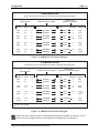
All 8 ports on the AM-318-00 are contained in one 50-pin RJ-21 connector, using these pinouts:
Port
0
Signal
Receive data
Request to send
Transmit data
Clear to send
Signal ground
1
Receive Data
Request to send
Transmit data
Clear to send
Signal ground
2
Receive Data
Request to send
Transmit data
Clear to send
Signal ground
3
Receive Data
Request to send
Transmit data
Clear to send
Signal ground
RXD
RTS
TXD
NC
CTS
GND
Pin #
26
1
27
2
28
3
Port
4
RXD
RTS
TXD
NC
CTS
GND
29
4
30
5
31
6
5
RXD
RTS
TXD
NC
CTS
GND
32
7
33
8
34
9
6
RXD
RTS
TXD
NC
CTS
GND
35
10
36
11
37
12
7
Signal
Receive Data
Request to send
Transmit data
Clear to send
Signal ground
Receive Data
Request to send
Transmit data
Clear to send
Signal ground
Receive Data
Request to send
Transmit data
Clear to send
Signal ground
Receive Data
Request to send
Transmit data
Clear to send
Signal ground
RXD
RTS
TXD
NC
CTS
GND
Pin #
38
13
39
14
40
15
RXD
RTS
TXD
NC
CTS
GND
41
16
42
17
43
18
RXD
RTS
TXD
NC
CTS
GND
44
19
45
20
46
21
RXD
RTS
TXD
NC
CTS
GND
47
22
48
23
49
24
For more information on cabling the AM-318-00, please see Installation Instructions: AM-318 Serial I/O
Controller, PDI-00318-00.
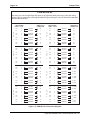
Cabling Packages
The following cable packages are available from Alpha Micro to use with the RJ-45 jacks provided by
the on-board serial ports of the Eagle 450, the ports from an AM-318-10, or AM-314 or AM-318-00
ports using AM-90 cards. These are the same kits used for the AM-359 cards in large AMOS systems
such as the AM-6000.
The cabling configurations described in this appendix meet the USOC (United Standards
Organization Committee) Standards.
Eagle 450 Installation and Technical Manual, Rev. 00
Configuration
Page 3-9
• PDB-00359-50—For configurations where the Eagle 450 ports are replacing an AM-355. The kit
includes eight PRA-00243-04 cable assemblies. Each assembly has a four-foot parallel patch
cord with an RJ-45 connector at one end and a modular female DB9 connector at the opposite
end. You simply plug the RJ-45 connector into the Eagle 450 and the female DB9 into the male
DB9 connector previously plugged into the AM-355 board.
• PDB-00359-51—Connects the Eagle 450 ports to an existing six-wire patch panel using a threepair wiring system. The cable assembly has eight RJ-45 connectors with six wires each, which
plug into the two AM-90 boards attached to Eagle 450 ports. The opposite end of the cable
assembly is a female RJ-21 connector which plugs into your six-wire patch panel.
This cabling kit (PDB-00359-51) does not support DCD for modems, but it does support
DTR.
• PDB-00359-52—Connects the Eagle 450 ports to an eight-wire patch panel using a four-pair
wiring system. The cable assembly has six RJ-45 connectors with eight wires each, which plug
into six Eagle 450 RJ-45 connectors. The opposite end of the cable assembly is a female RJ-21
connector which plugs into your eight-wire patch panel. This kit also includes two of the fourfoot long RJ-45 to female DB9 connectors used in the PDB-00359-50 cabling kit, for the two
ports not plugged into the patch panel.
• PDB-00359-53—Four RJ-45 to male DB25 adapters for connecting modems to the Eagle 450.
This kit requires a shielded parallel patch cord with RJ-45 connectors at each end, like the 10foot PRA-00189-10 cable in the PDB-00359-56 cabling kit described below.
• PDB-00359-54—Four modular RJ-45 to male DB25 adapters for connecting printers and
terminals to the Eagle 450 ports. This kit requires a shielded parallel patch cord with RJ-45
connectors at each end, like the 10-foot PRA-00189-10 cable supplied in the PDB-00359-56
cabling kit described below.
• PDB-00359-55—Four modular RJ-45 to female DB9 adapters for connecting a PC-AT style
serial port to an Eagle 450 port. This kit requires a shielded parallel patch cord with RJ-45
connectors at each end, like the 10-foot PRA-00189-10 cable supplied in the PDB-00359-56
cabling kit described below.
• PDB-00359-56—This kit includes four (PRA-00189-10) 10 foot shielded parallel patch cords
with RJ-45 connectors at each end.
The following illustrations contain signal and pinout information for each of the PDB-00359-5x cabling
kits:
Eagle 450 Installation and Technical Manual, Rev. 00
Page 3-10
Chapter Three
PDB-00359-50
Use this kit when replacing an AM-355 board with Eagle 450 ports.
FOUR FOOT CABLE
AM-90 BOARD
SIGNAL
FEMALE DB9
AM-355
PINOUTS
SIGNAL
WHT/BLU
BLU/WHT
2
5
RXD
RTS
3
6
WHT/ORG
ORG/WHT
3
9
TXD
DTR
P3+
P3-
2
7
WHT/GRN
GRN/WHT
4
7
CTS
GND
P4+
P4-
8
1
WHT/BRN
BRN/WHT
8
1
DCD
SHLD
PAIR #
RJ-45
RXD
RTS
P1+
P1-
5
4
TXD
DTR
P2+
P2-
CTS
GND
DCD
SHLD
Figure 3-2: PDB-00359-50 External Cabling Kit
Eagle 450 Installation and Technical Manual, Rev. 00
Configuration
Page 3-11
PDB-00359-51
Use this kit to attach an Eagle 450 to an existing six-wire patch
panel using a three-pair wiring system.
AM-90 BOARD
PAIR # RJ-45
P
O
R
T
P1+
P1-
5
4
WHT/BLU
BLU/WHT
26
1
P2+
P2-
3
6
WHT/ORG
ORG/WHT
27
2
P3+
P3-
2
7
WHT/GRN
GRN/WHT
28
3
P1+
P1-
5
4
WHT/BLU
BLU/WHT
29
4
P2+
P2-
3
6
WHT/ORG
ORG/WHT
30
5
P3+
P3-
2
7
WHT/GRN
GRN/WHT
31
6
P1+
P1-
5
4
WHT/BLU
BLU/WHT
32
7
P2+
P2-
3
6
WHT/ORG
ORG/WHT
33
8
P3+
P3-
2
7
WHT/GRN
GRN/WHT
34
9
P1+
P1-
5
4
WHT/BLU
BLU/WHT
35
10
P2+
P2-
3
6
WHT/ORG
ORG/WHT
36
11
P3+
P3-
2
7
WHT/GRN
GRN/WHT
37
12
1
P
O
R
T
P1+
P1-
5
4
WHT/BLU
BLU/WHT
38
13
P2+
P2-
3
6
WHT/ORG
ORG/WHT
39
14
P3+
P3-
2
7
WHT/GRN
GRN/WHT
40
15
P
O
R
T
P1+
P1-
5
4
WHT/BLU
BLU/WHT
41
16
P2+
P2-
3
6
WHT/ORG
ORG/WHT
42
17
P3+
P3-
2
7
WHT/GRN
GRN/WHT
43
18
P1+
P1-
5
4
WHT/BLU
BLU/WHT
44
19
P2+
P2-
3
6
WHT/ORG
ORG/WHT
45
20
P3+
P3-
2
7
WHT/GRN
GRN/WHT
46
21
P1+
P1-
5
4
WHT/BLU
BLU/WHT
47
22
P2+
P2-
3
6
WHT/ORG
ORG/WHT
48
23
P3+
P3-
2
7
WHT/GRN
GRN/WHT
49
24
6
3
P
O
R
T
P
O
R
T
FEMALE RJ21
CONNECTOR
5
2
P
O
R
T
AM-90 BOARD
PAIR # RJ-45
FEMALE RJ21
CONNECTOR
P
O
R
T
7
4
P
O
R
T
8
Figure 3-3: PDB-00359-51 External Cabling Kit
Eagle 450 Installation and Technical Manual, Rev. 00
Page 3-12
Chapter Three
PDB-00359-52
Use this kit to connect eight Eagle 450 ports to an eight-wire patch panel using a four-pair wiring
system. This kit creates two extra eight-wire AM-355 type ports (ports 7 and 8), which have standard
female DB9 connectors.
AM-90 BOARD
PAIR # RJ-45
P
O
R
T
1
P
O
R
T
2
AM-90 BOARD
PAIR # RJ-45
FEMALE RJ21
CONNECTOR
P1+
P1-
5
4
WHT/BLU
BLU/WHT
26
1
P2+
P2-
3
6
WHT/ORG
ORG/WHT
27
2
P3+
P3-
2
7
WHT/GRN
GRN/WHT
28
3
P4+
P4-
8
1
WHT/BRN
BRN/WHT
P1+
P1-
5
4
P2+
P2-
FEMALE RJ21
CONNECTOR
P1+
P1-
5
4
WHT/BLU
BLU/WHT
42
17
P2+
P2-
3
6
WHT/ORG
ORG/WHT
43
18
P3+
P3-
2
7
WHT/GRN
GRN/WHT
44
19
29
4
P4+
P4-
8
1
WHT/BRN
BRN/WHT
45
20
WHT/BLU
BLU/WHT
30
5
P1+
P1-
5
4
WHT/BLU
BLU/WHT
46
21
3
6
WHT/ORG
ORG/WHT
31
6
P2+
P2-
3
6
WHT/ORG
ORG/WHT
47
22
P3+
P3-
2
7
WHT/GRN
GRN/WHT
32
7
P3+
P3-
2
7
WHT/GRN
GRN/WHT
48
23
P4+
P4-
8
1
WHT/BRN
BRN/WHT
33
8
P4+
P4-
8
1
WHT/BRN
BRN/WHT
49
24
P1+
P1-
5
4
WHT/BLU
BLU/WHT
34
9
P1+
P1-
5
4
WHT/BLU
BLU/WHT
2
5
GRN
RED
P2+
P2-
3
6
WHT/ORG
ORG/WHT
35
10
P2+
P2-
3
6
WHT/ORG
ORG/WHT
3
9
BLK
YEL
P3+
P3-
2
7
WHT/GRN
GRN/WHT
36
11
P3+
P3-
2
7
WHT/GRN
GRN/WHT
4
7
ORG
BRN
P4+
P4-
8
1
WHT/BRN
BRN/WHT
37
12
P4+
P4-
8
1
WHT/BRN
BRN/WHT
8
1
SLT
BLU
P1+
P1-
5
4
WHT/BLU
BLU/WHT
38
13
P1+
P1-
5
4
WHT/BLU
BLU/WHT
2
5
GRN
RED
P2+
P2-
3
6
WHT/ORG
ORG/WHT
39
14
P2+
P2-
3
6
WHT/ORG
ORG/WHT
3
9
BLK
YEL
P3+
P3-
2
7
WHT/GRN
GRN/WHT
40
15
P3+
P3-
2
7
WHT/GRN
GRN/WHT
4
7
ORG
BRN
P4+
P4-
8
1
WHT/BRN
BRN/WHT
41
16
P4+
P4-
8
1
WHT/BRN
BRN/WHT
8
1
SLT
BLU
P
O
R
T
5
P
O
R
T
6
FEMALE DB9
P
O
R
T
3
P
O
R
T
7
FEMALE DB9
P
O
R
T
4
P
O
R
T
8
Figure 3-4: PDB-00359-52 External Cabling Kit
Eagle 450 Installation and Technical Manual, Rev. 00
Configuration
Page 3-13
PDB-00359-53
Use this kit to connect a modem to the Eagle 450 with full handshaking support.
SIGNAL
MALE DB25
ADAPTER = MODEM
PARALLEL PATCH CORD
AM-90 BOARD
DB25
PINOUTS
PAIR #
RJ-45
RJ-45
SIGNAL
RXD
RTS
P1+
P1-
5
4
WHT/BLU
BLU/WHT
5
4
GRN
RED
3
4
TXD
CTS
TXD
DTR
P2+
P2-
3
6
WHT/ORG
ORG/WHT
3
6
BLK
YEL
2
20
RXD
DTR
CTS
GND
P3+
P3-
2
7
WHT/GRN
GRN/WHT
2
7
ORG
BRN
5
7
RTS
GND
DCD
SHLD
P4+
P4-
8
1
WHT/BRN
BRN/WHT
8
1
SLT/WHT
BLU
8
1
DCD
SHLD
Figure 3-5: PDB-00359-53 External Cabling Kit
PDB-00359-54
Use this kit to connect all terminals and printers to the Eagle 450 AM-90 ports.
PARALLEL PATCH CORD
AM-90 BOARD
SIGNAL
MALE DB25
ADAPTER = CRTs/PRINTERS
DB25
PINOUTS
PAIR #
RJ-45
RJ-45
SIGNAL
RXD
RTS
P1+
P1-
5
4
WHT/BLU
BLU/WHT
5
4
GRN
RED
2
5
TXD
CTS
TXD
DTR
P2+
P2-
3
6
WHT/ORG
ORG/WHT
3
6
BLK
YEL
3
8
RXD
DCD
CTS
GND
P3+
P3-
2
7
WHT/GRN
GRN/WHT
2
7
ORG
BRN
20
7
DTR
GND
DCD
SHLD
P4+
P4-
8
1
WHT/BRN
BRN/WHT
8
1
SLT/WHT
BLU
4
1
RTS
SHLD
*
* CRT or printer busy
Figure 3-6: PDB-00359-54 External Cabling Kit
Both of the above cable kits require a shielded parallel patch cord with RJ-45 connectors at each
end, like the 10 foot PRA-00189-10 cables supplied in the PDB-00359-56 cabling kit.
Eagle 450 Installation and Technical Manual, Rev. 00
Page 3-14
Chapter Three
PDB-00359-55
Use this kit to connect a PC-AT style serial port to an Eagle 450 AM-90 port.
SIGNAL
FEMALE DB9
ADAPTER = PC-AT
PARALLEL PATCH CORD
AM-90 BOARD
DB9
PINOUTS
PAIR #
RJ-45
RJ-45
RXD
RTS
P1+
P1-
5
4
WHT/BLU
BLU/WHT
5
4
GRN
RED
3
8
SIGNAL
TXD
CTS
TXD
DTR
P2+
P2-
3
6
WHT/ORG
ORG/WHT
3
6
BLK
YEL
2
1
RXD
DCD
CTS
GND
P3+
P3-
2
7
WHT/GRN
GRN/WHT
2
7
ORG
BRN
7
5
RTS
GND
DCD
SHLD
P4+
P4-
8
1
WHT/BRN
BRN/WHT
8
1
SLT/WHT
BLU
4
nc
DTR
no connect
Figure 3-7: PDB-00359-55 External Cabling Kit
The above cable kit requires a shielded parallel patch cord with RJ-45 connectors at each end, like
the 10 foot PRA-00189-10 cables supplied in the PDB-00359-56 cabling kit.
PARALLEL I/O SUPPORT
The Eagle 450 includes one parallel port, with a 25-pin connector on the back panel. This port supports
the industry-standard Centronics interface. The signal pinouts for the parallel port are as follows:
Pin #
1
2
3
4
5
6
7
8
9
10
11
12
13
Signal Name
Data strobe
Data 1
Data 2
Data 3
Data 4
Data 5
Data 6
Data 7
Data 8
Acknowledge
Busy
Paper error
Select
Pin #
14
15
16
17
18
19
20
21
22
23
24
25
Signal Name
Auto line-feed (not used)
Error
Printer reset
Select in
Ground
Ground
Ground
Ground
Ground
Ground
Ground
Ground
Eagle 450 Installation and Technical Manual, Rev. 00
Configuration
Page 3-15
For best reliability and printer performance, your parallel printer cable should be no longer than
six feet.
NETWORK CONFIGURATION
The Eagle 450 includes as standard both an RJ-45 10BaseT and a 15-pin AUI Ethernet connector
attached to the on-board Ethernet controller. You can use either connector to attach the Eagle 450 to your
network, then use AlphaTCP for industry-standard TCP/IP networking on your LAN or the Internet.
You cannot use both Ethernet ports at the same time.
10BaseT Cabling
10BaseT connections use 100 ohm unshielded twisted pairs, with at least two pairs per cable (one set of
pairs for transmitting data and another for receiving). 10BaseT cables terminate in eight pin RJ-45
connectors with the following pin assignments:
RJ-45 Pin
Number
1
2
3
6
Signal Name
Transmit Data +
Transmit Data Receive Data +
Receive Data -
The 10BaseT specification allows a maximum distance of 100m (approx. 300 feet) between the computer
and hub.
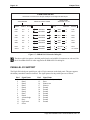
EAGLE 450 UPS STATUS PORT
The UPS status port on the back panel of the Eagle 450 is a male DB-9 connector. The UPS system also
has a male DB-9 connector for its switch contact port. To connect the UPS to the computer you need a
cable with two female DB-9 connectors. The following table shows the pinout connections required to
make this cable. You need an 8-wire cable, and both grounds are necessary!
Signal Name
FAULT
GND
GND
ON BYPASS
LOW BATTERY
INVERTER ON
AC PWR FAIL
DB-9 Pin #
(CPU End)
DB-9 Pin #
UPS End
3
2
5
6
7
8
9
1
2
5
6
7
8
9
Eagle 450 Installation and Technical Manual, Rev. 00
Chapter 4 - Installation
This chapter describes what you have to do to get the Eagle 450 up and running. It covers:
• Site requirements and preparation
• Unpacking and preparing the computer
• Initial setup and testing
• Setting CMOS options
• Modifying the initialization file
• Adding user names
SITE REQUIREMENTS
Like any other computer, the Eagle 450 requires an appropriate site. When choosing where to place the
computer, consider these conditions:
• Size: Make sure the computer and any other equipment, such as external peripherals, terminals,
or printers, will fit with enough room for cables, ventilation, workspace, etc. There must be at
least six inches of space behind the main cabinet for ventilation, and cable connections could
need even more.
• Power: The computer must have enough reliable, properly regulated electrical power. It may be a
good idea to test the line voltage. Many power companies will install test equipment to
determine if you need additional line regulation. You can also test line voltages using a highspeed line transient recorder. If, over several days, the line voltage varies more than 10 percent
from the rated line voltage, you may need a power conditioner and a new, dedicated AC power
circuit.
To avoid electrical interference, sources of electrical noise such as air conditioners, copiers, or
cleaning equipment should not be connected to the same power circuit as the computer.
There must be enough outlets for the computer and any peripherals. These outlets should have a
common grounding point restricted to only those connections coming from the computer
installation. If you must use extension cords, be sure the cords are rated for the full amount of
current the computer or peripheral requires. For the main computer, the cord rating should be at
least 15 amps.
Power requirements are listed in the Specification chapter, on page 2-1.
• Static: Static electricity can cause the computer to reboot unexpectedly, and can even damage or
destroy internal components. Ideally, the computer should not be in a carpeted area. If it must be,
use anti-static spray as necessary or install an air conditioner which controls humidity to reduce
static electricity.
• Temperature and humidity: The computer is fairly tolerant, but extreme conditions can keep it
from working properly. Temperature and humidity limits are given in the Specifications chapter,
on page 2-1.
Eagle 450 Installation and Technical Manual, Rev. 00
Page 4-2
Chapter Four
• Cabling: The RS-232 cables to any serial terminals and printers should generally not be longer
than 50 feet, and, to avoid interference, should not be too near telephone cables or high-voltage
lines. They also shouldn’t be in elevator shafts or cross walkways.
Parallel printer cables normally should be six feet or shorter. External SCSI cables also have
length restrictions, as discussed in Chapter 3. If you have printers or external SCSI devices,
make sure the places for them are close enough to the main cabinet.
• Cleanliness: Try to locate the computer out of harm’s way, where no one is likely to spill food or
drink into it, or use its top as a spare table. Dust and dirt can clog the fans and cause heat
problems, so keep the computer in a clean, low-traffic area if possible.
UNPACKING AND PREPARING THE EAGLE 450
Unpack the computer and save all packing material and cartons. When re-shipping or otherwise
transporting your computer, you must use the original packaging to ensure safe shipment.
Make sure you have all the equipment you ordered: computer, terminals, cables, and so on. If anything is
missing, or if it appears any equipment was damaged during shipment, please contact Alpha Micro Sales
Order Administration.
Before turning on the computer for the first time, we suggest you open the chassis and make sure all
boards are properly seated and cables are securely attached. While the computer was tested at the factory,
rough handling during shipment can vibrate connectors loose and keep the system from working.
Checking the AC Voltage Setting
Before plugging in the computer for the first time, check the voltage switch on the back panel.
Make sure it is set correctly to 115 or 230 Volts. Turning on the computer with the voltage switch
on the wrong setting can seriously damage the computer.
The voltage switch is next to the power cord plug, as shown on the picture of the Eagle 450 back panel in
Chapter 3.
Recording the SSD Identification Number
The SSD for the AM-138 board in the Eagle 450 is written on the system ID label on the back of the
computer. Please enter the SSD on the Contact Information Sheet in the Eagle 450 Owner’s Manual so
the customer has it easily available if needed.
Eagle 450 Installation and Technical Manual, Rev. 00
Installation
Page 4-3
INITIAL SETUP AND TESTING
Before connecting the entire installation, it’s a good idea to test the main computer by itself and with
only the operator terminal attached. So, follow this procedure:
1. Again, check the voltage switch on the back panel to make sure it’s set correctly.
2. Attach the operator terminal to serial port 0 on the back panel. See the back panel picture in
Chapter 3 for the port location. By default, port 0 is set to an Alpha Micro terminal at 19.2K
baud.
3. Plug the computer in.
4. To start the self test, hold down the Reset button on the front panel while you press the Power
button to turn the computer on. If you aren’t familiar with the front panel of the Eagle 450, see
the Eagle 450 Computer Owner’s Manual.
See the System Self Test User’s Guide for information on running the self test and interpreting its
results. If the computer doesn’t come on, the self test doesn’t start, or the self test finds a
problem, see Chapter 5, “Troubleshooting.”
5. After the self test has completed a full cycle of test, press Reset to end the test and boot the
computer.
Do not press Reset to end self test during the disk test portion. Doing so could damage the data on
the disk!
The computer should now boot using the default initialization file. Assuming it does so successfully, you
can continue by modifying the CMOS settings and/or the system initialization file.
MODIFYING THE CMOS SETTINGS
When booting, the Eagle 450 uses data stored in its CMOS parameters to find the primary and alternate
boot devices, the system monitor and initialization files to use, and other system options. The CMOS
RAM is on the AM-138 board; it is battery backed up and write-protected for data integrity.
You can change the CMOS configuration even if you can’t boot the computer under AMOS. This can be
very useful in case of certain system problems. To change the CMOS configuration, you must have a
terminal attached to port 0 on the AM-138 system board. The first time you access CMOS, this terminal
must be set to 19.2K baud; you can then change the terminal speed setting if you want.
It’s a good idea to write down the CMOS settings. If you need to replace the batteries, as
described in the Eagle 450 Service Manual, the settings are lost and must be re-entered.
Eagle 450 Installation and Technical Manual, Rev. 00
Page 4-4
Chapter Four
Eagle 450 Initialization Routine
Before relying on the CMOS parameters, the AM-138 boot code checks the validity of the CMOS
contents by verifying the parameter checksum. If the checksum verifies, the system front panel displays
"C5" while it verifies CMOS, and boots using the current CMOS parameters. If you want to change the
CMOS parameters, press ESC when the "C5" displays (you have approximately three seconds). This
displays the CMOS configuration menu, as described below.
If the CMOS checksum test fails, the front panel will blink "CE" for several seconds, then switch to
"CC" while the boot code tests CMOS RAM to ensure that it is working. If the RAM test fails, the boot
code displays "CF" on the front panel and the system tries to boot using the default settings shown
below. If this is the case, contact Alpha Micro's Technical Assistance Center.
CMOS Menu Options
To enter CMOS Setup, first make sure no one else is using the computer. Then, press the Reset button.
When "C5" appears on the front display panel, press ESC on the boot terminal to interrupt the boot
process and access the CMOS Configuration menu. You have about three seconds to press ESC .
The port 0 terminal’s baud rate must match the current CMOS setting (default is 19.2K), or CMOS
will not recognize the ESC character.
The CMOS menu looks like this:
ALPHA MICROSYSTEMS
AM-138 CMOS Configuration Menu
Primary boot device type . . . . . .
Primary boot device unit # . . . . .
SCSI Disk
0
Alternate boot device type . . . . .
Alternate boot device unit # . . . .
Streamer
3
Boot monitor file name . . . . . . .
Boot initialization file name . . .
AMOS32.MON
AMOS32.INI
Network interface type . . . . . . . TPI
Serial port 0 speed . . . . . . . . .19,200
Display console boot messages . . . .Yes
Use [UP] and [DOWN] keys to select an item.
Use [LEFT] and [RIGHT] keys to change item.
Press [ESCAPE] when done.
As indicated, you use the and keys to select a parameter. To change a parameter, use the
keys to cycle through its possible settings. The only exceptions are file names, which you type.
and
The CMOS menu fields are:
Eagle 450 Installation and Technical Manual, Rev. 00
Installation
Page 4-5
Primary Boot Device Type
This is the type of device to boot from if the attempt to boot from the alternate device fails or no alternate
device is selected. For the Eagle 450, this should always be set to SCSI Disk; do not select Flash.
Primary Boot Device Unit #
This sets which primary drive number to boot from. Valid unit numbers are 0-6 and 8-15 (only 0-6 when
using the narrow SCSI bus).
Alternate Boot Device Type
This is the type of device to attempt to boot from first, before using the primary boot device. Currently
supported alternate boot devices are Streamer, SCSI Disk (which includes the SCSI floppy disk), or
None (boot from primary device only). You should not choose Flash or Xmodem on the Eagle 450.
Alternate Boot Device Unit #
This selects which alternate device number to boot from. Valid unit numbers are 0-6 and 8-15 (only 0-6
when using the narrow SCSI bus). You should know how many devices are attached to the system before
you enter this number. If you select a number and the device is not found, the system will boot from the
primary boot selection.
Boot Monitor File Name
Type the name of the monitor file to be loaded during boot. Any valid file name, with an .MON
extension, can be used. The monitor file must exist in account [1,4] of the first logical disk of the
selected boot device. This parameter is not used when booting from a tape device. You can use the
backspace and the arrow keys to edit this field.
Boot Initialization File Name
Type the name of the system initialization (INI) file to be used during boot. Any valid file name, with an
.INI extension, can be used. The INI file must exist in account [1,4] of the first logical disk of the
selected boot device. You can use the backspace and the arrow keys to edit this field.
Network Interface Type
Choose which Ethernet interface connector to use on the AM-138 board. There are two possible
selections: AUI (DB-15), or TPI (RJ-45 10BaseT).
Serial Port 0 Speed
By default, CMOS requires a port 0 terminal set to 19.2K baud. You can change this to 1200, 9600, or
38.4K. The speed you set here should match the port 0 definition in the system initialization file. If the
terminal’s baud rate does not match this setting, you won’t be able to re-enter the CMOS menu, since
CMOS will not recognize it when you press ESC .
Eagle 450 Installation and Technical Manual, Rev. 00
Page 4-6
Chapter Four
Display Console Boot Messages
When set to Yes, this option displays status messages on the operator terminal during booting. These
messages are equivalent to each of the front panel status codes normally displayed during booting, and
are normally only needed if you cannot see the status display.
Saving the CMOS Settings
When you are finished making changes press ESC . A message will appear at the bottom of the screen
asking if you wish to save any changes made. Type Y to save the changes in the CMOS RAM, or N to
abandon any changes made. After you enter your response, the system will boot using the new
parameters, if you saved them.
Important Note
If you want to boot from a physical disk device other than device ID 0, you should create a disk driver
for the selected drive ID and MONGEN it into the monitor. You must do this if you want to be able to
MONTST using your boot monitor. While a hardware reset will work if the monitor contains the generic
SCZ138.DVR, because it reads the drive ID from CMOS, MONTST does not look at the CMOS settings,
and so will not know which drive to boot from unless the drive ID is embedded in the driver.
MODIFYING THE INITIALIZATION FILE
The modifications you’ll need to make to the default system initialization command file for the Eagle
450 are similar to the modifications for other AMOS computers. You’ll probably want to set the number
of jobs, add programs to system memory, set up AlphaTCP networking, define terminals and printers,
and so on. You may also want to change SCSI dispatcher options, set read-ahead, or disable Super I/O
for some or all serial ports.
The name of the system initialization file for the Eagle 450 is usually AMOS32.INI (though, because of
the CMOS feature, it can have any name you want).
NEVER change the system initialization file directly! Always make a copy of it and modify the
copy. While the ability to change the initialization file name through CMOS can make it possible
to boot even if you invalidate the normal initialization file, it is still safer to work in a copy of the
file.
To make a copy of the system initialization file to modify and test:
1. Log into DSK0:[1,4] and copy the file:
LOG DSK0:[1,4] ENTER
COPY TEST.INI=AMOS32.INI
ENTER
2. Use AlphaVUE or another text editor to edit the contents of the test file:
VUE TEST.INI
ENTER
Eagle 450 Installation and Technical Manual, Rev. 00
Installation
Page 4-7
3. Make all the necessary changes to TEST.INI. Save the file when exiting AlphaVUE by pressing
the ESC key and typing F. Some of the common changes you’ll make are discussed below.
4. Make sure no one else is using the computer and use MONTST to insure TEST.INI works as
expected:
LOG OPR: ENTER
MONTST TEST.INI
ENTER
5. After you have successfully tested TEST.INI and you are satisfied with the results, copy it back
to AMOS32.INI.
Be careful not to rename the TEST.INI file too soon. You might want to let the computer
run awhile to test out the new configuration before you rename it. If you decide you don't
want to keep the new configuration, you can always press the Reset button to reboot with
your former system initialization file.
Follow this procedure any time you modify the system initialization file.
Do not change any lines in the system initialization file unless you're familiar with them and
understand their ramifications. For more information on the initialization file, refer to the System
Operator's Guide to the System Initialization Command File, DSO-00002-00.
Eagle 450 Installation and Technical Manual, Rev. 00
Page 4-8
Chapter Four
:T
;
JOBS 5
;
JOBALC JOB1
;
QUEUE 2000
;
TRMDEF TERM1,A31810=0:19200,ALPHA,200,200,200,EDITOR=15
;
PARITY
; Clear memory
VER
; Unlock keyboard
;
SCZDSP SCZ138.SYS/ET
; SCSI dispatcher
;
DEVTBL DSK
DEVTBL TRM,RES,MEM
DEVTBL /STR0
; Streaming tape device
;
BITMAP DSK
; Paged bitmaps for AMOS 2.X
;
ERSATZ ERSATZ.NEW
MSGINI 20K
;
SYSTEM SYSMSG.USA
SYSTEM DCACHE.SYS/N/M 1M
; Enable disk read-caching
SYSTEM DVR:DSK/N 100K 60
; Enable disk write-caching
SYSTEM CMDLIN.SYS
SYSTEM SCNWLD.SYS
SYSTEM QFLOCK.SYS
SYSTEM TRM.DVR[1,6]
SYSTEM STR.DVR[1,6]
SYSTEM EGP.DVR[1,6]
SYSTEM
;
SET DSKERR
;
MOUNT DSK:
;
MEMORY 0
Simple Initialization File
Defining the Parallel Port
The Eagle 450 contains one parallel port, which is not automatically defined for you. To enable the
parallel port:
1. Type the following statement following the last DEVTBL statement in your TEST.INI file:
DEVTBL /EGP0
2. Load the parallel printer driver into system memory using a SYSTEM statement:
SYSTEM EGP.DVR[1,6]
Eagle 450 Installation and Technical Manual, Rev. 00
Installation
Page 4-9
3. To connect a printer to the parallel port, change the DEVICE statement in the printer
initialization file to reference parallel port 0 (EGP0:). For example:
DEVICE=EGP0:
For information on printer initialization files and printer spoolers, see the System Operator's Guide. For
cable pinouts for a parallel printer, see Chapter 3.
Defining Ports and Jobs
When the Eagle 450 leaves Alpha Micro, only the operator terminal is defined in the initialization file.
After installation, you’ll want to define any other terminals and serial printers. To do this, you need to:
• Define additional jobs
• Define the terminal or printer connected to each serial port
• Attach the appropriate job to each defined terminal or printer.
Before adding jobs to the system, make sure its AMOS license allows the number of jobs you’re
defining.
The steps below outline the process of defining the terminals and printers:
1. Make a copy of the initialization file, as discussed previously.
2. At the beginning of the TEST.INI file is a JOBS statement. The number following the JOBS
statement represents the total number of jobs on the computer. Change the number in the JOBS
statement to the number of jobs needed. For example:
JOBS 17
When calculating the number of jobs, be sure to include all the jobs the computer will
use: background jobs, printer jobs, network connections, and so on. It’s often a good idea
to add a few extra when possible.
3. On the lines following the JOBS statement, there are one or more JOBALC statements. You can
define each job in a separate JOBALC statement, or you can define several jobs in the same
JOBALC statement by separating the jobnames with commas. For example:
JOBALC JOB4,JOB5
Jobnames can have up to six characters (A - Z, 0 - 9, $). Each jobname defines a job on your
computer. The total number of jobs defined in JOBALC statements must be equal to or less than
the number in the JOBS statement.
4. Next, define the devices attached to the serial ports using TRMDEF statements. Here is a sample
TRMDEF statement:
TRMDEF TERM2,A31810=1:19200,ALPHA,200,200,200,EDITOR=10
Using the sample, here's the information you must tell AMOS about a terminal:
• TERM2 is the terminal name. You may use any name containing six or fewer letters
and/or numbers. Each terminal must have a different name.
Eagle 450 Installation and Technical Manual, Rev. 00
Page 4-10
Chapter Four
• A31810 is the name of the interface driver (without the .IDV extension) for the circuit
board the terminal is connected to. The ports on an Eagle 450 use these interface drivers:
• A31810: The eight serial ports on the AM-138 system board
• A31810: Ports on an AM-318-10 board
• AM318: Ports on an AM-318-00 or -02 board
• AM314: Ports on an AM-314 board
• 1 is the number of the port the terminal is attached to. The port number is octal, and
depends on the port the terminal is attached to on the I/O board, and the I/O expansion slot
the board is in. This table gives the port numbers for each board type/slot combination:
Expansion Slot
Any AM-318 (-00,
-02, or -10)
AM-314
J7
10-17
J8
20-27
J9
30-37
10-13
20-23
30-33
Use these numbers even if it means you skip some numbers. For example, if you have an
AM-314 board in J7 and an AM-318-10 in J8, the AM-318-10 ports are numbered from
20-27, and numbers 14-17 are not used.
•
•
•
•
The eight ports on the AM-138 are numbered from 0-7.
19200 is the baud rate of the terminal.
ALPHA is the name of the terminal driver. ALPHA can be used for most Alpha Micro
terminals; you can change this to a driver specifically for the terminal if one exists.
200,200,200 are buffer sizes, expressed in number of characters. Different situations may
require other buffer sizes, but this is typical.
EDITOR=15 enables the line editor for this terminal. See the AMOS User's Guide for
more information on the line editor.
5. Use a SETJOB statement for each terminal defined in a TRMDEF statement to link it to a job
defined in a JOBALC statement. You can include parameters in the SETJOB statement to:
• Define how much memory to allocate to a specific job.
• Define the specific disk and account you want the specific job to log into each time the
computer boots.
• Unlock the terminal’s keyboard (with the VER command).
SETJOB statements must be after the last SYSTEM statement in the .INI file. Here is a sample:
SETJOB JOB4,TERM2,256K,LOG DEMO,VER
6. Add a WAIT command to give the computer time to process the commands for the job before it
proceeds with the rest of the initialization file.
WAIT JOB4
7. When you have added SETJOB and WAIT statements for each job, perform a test reboot, using
the procedure earlier in this chapter.
For more information on defining jobs and terminals, see the System Operator's Guide to the System
Initialization Command File.
Eagle 450 Installation and Technical Manual, Rev. 00
Installation
Page 4-11
AlphaTCP Setup
If your Eagle 450 is connected to a network, the AlphaTCP networking software allows any network
user—and any external user who has access to your network—to use the programs and files on the Eagle
450. To use AlphaTCP, which is included with AMOS on the Eagle 450, you must start various
background “server” jobs to handle the network traffic and other tasks, and assign memory for use by
people requesting a connection over the network.
The initialization file setup for using the AlphaTCP networking software can be involved, and in addition
to changing your initialization file, you need to modify the AlphaTCP configuration files at installation,
and possibly when you add new network users.
Configuring your initialization file to make the best use of your resources with AlphaTCP is too lengthy
a process to discuss here. Please see your AlphaTCP Administrator’s Guide, DSO-00187-00, especially
chapters 3 and 4, for detailed information and instructions.
When defining the network driver for the Eagle 450, in most situations you should use AM138.LDV for
best performance. In certain circumstances—for example, if you need to perform wildcarded AMOS
copy commands across the network—use AM138.NDV instead.
Changing User Memory
In addition to the operating system itself, the memory of the Eagle 450 is used by:
• The serial ports on the AM-138 and any added I/O boards
• Background processes, such as the AlphaTCP server programs
• People connecting to the computer over the network
Whenever you change any memory allocation, you need to balance all three types of requirements.
You can display the current memory allocations on your computer using the STAT or SYSTAT
command. Neither STAT nor SYSTAT show how much memory is left in the SMEM memory
pool.
The amount of memory for each serial port and background process is set in a SETJOB statement in the
initialization file (except for serial port 0, which usually receives all of the memory not used for any
other purpose). Each network user, however, may be able to request a specific amount of memory when
he or she connects to the computer (depending on the AlphaTCP configuration, network users may be
assigned a memory size automatically). So, rather than assigning memory individually to each job, the
initialization file merely allocates a “pool” of memory for network jobs. When someone connects to the
Eagle 450, memory is taken from this pool and assigned to that network user; when the user disconnects,
the memory is returned to the pool.
The size of this memory pool is set by an SMEM (shared memory) statement in the initialization file.
The memory pool allocated by SMEM is also used for some other purposes, such as spawned MULTI
jobs, but for this discussion we’ll consider that it’s all available for network users.
Eagle 450 Installation and Technical Manual, Rev. 00
Page 4-12
Chapter Four
If you decide to change the amount of memory allocated to a job, or the memory pool, you can modify
the system initialization file following the instructions below.
Be very careful when changing memory allocations. If your Eagle 450 uses AlphaTCP
networking, most of the memory could be used for AlphaTCP processes and users connected via
the network. Allocating memory incorrectly could make it impossible for some or all network
users to access the computer. Also, changing the memory for AlphaTCP processes or available
for network users may require changes to one or more of the AlphaTCP configuration files in
addition to the initialization file. Be sure to refer to the AlphaTCP Administrator’s Guide, DSO00187-00, before changing any aspect of AlphaTCP’s memory use.
Also, please refer to the System Operator’s Guide to the System Initialization Command File for
more information on SETJOB and SMEM.
1. Make a copy of the initialization file and edit it, as discussed previously.
2. To change the memory for a serial port or a background process, such as the AlphaTCP
TCPEMU server, scan through the file until you come to the SETJOB statement for that job. The
amount of memory for the job is immediately after the terminal name in the SETJOB statement.
You can increase or decrease this amount, as long as you keep in mind how much total memory
your computer has, and how much memory the other jobs, and the shared memory pool, need.
3. To change the amount of memory in the shared memory pool, find the SMEM statement; it
should be just after the last SYSTEM statement. Again, you can increase or decrease this
amount, but be sure to take all of your users’ memory needs into account.
Remember, the operator terminal—the one the computer boots on, connected to port #0—usually
gets all the memory not otherwise used. To increase the memory for this job, you need to
decrease memory use somewhere else; to decrease it, you can add memory to another job or the
memory pool.
You can assign a particular amount of memory to port #0 by using a FORCE command. If
you do this, any memory not assigned to any job or process is wasted.
4. When you’ve made your changes, save the TEST.INI file and exit AlphaVUE. Then, perform a
test reboot by running MONTST as described earlier in this chapter. You can then use the STAT
or SYSTAT command to see how much memory is assigned to each job.
SCSI Dispatcher Options
Like other computers in the Eagle family, the Eagle 450 uses a program called the SCSI dispatcher to
handle SCSI bus communication. The dispatcher for the Eagle 450 is called SCZ138.SYS. The provided
initialization file includes the command SCZDSP SCZ138.SYS to start the dispatcher. You may want to
add one or more of these options to that line:
Eagle 450 Installation and Technical Manual, Rev. 00
Installation
Page 4-13
Switch
Description
/ET
Enable tolerant active negation
/EW
/EW:{id#}
Enable Wide SCSI negotiation for all devices
Enable Wide SCSI negotiation for SCSI device ID#
/NQ
/NQ:{id#}
Disable Command Queuing for all devices
Disable Command Queuing for SCSI device ID#
/NS
/NS:{id#}
Disable Synchronous Negotiation for all devices
Disable Synchronous Negotiation for SCSI device ID#
/NP
Disable Parity Checking (Parity still generated) on all devices
We recommend that all Eagle 450s use the /ET switch to enable tolerant active negation. Using active
negation improves bus integrity when using synchronous data transfers.
Never attach a device to or remove a device from the SCSI bus while system power is on. This is
never a good idea, but active negation makes it even more likely that doing so will damage the
device, the SCSI controller, or both.
The most common of the other switches is /EW, to enable Wide SCSI operation when using the optional
Wide SCSI bus. For example, if you are using the Wide SCSI bus and have a Wide SCSI disk drive at ID
0, with narrow devices at other IDs, use this statement to enable Wide SCSI operation for just that drive:
SCZDSP SCZ138/ET/EW:0
If you have both Wide and narrow SCSI devices attached to the Wide bus, enable Wide SCSI operation
only for the Wide devices. Use /EW without a device ID (to enable Wide operation for the entire bus) if
all devices on the bus, both disk and tape drives, are Wide SCSI devices.
Do not use the /EW switch with the narrow SCSI bus, even if you have Wide SCSI devices attached to
the bus using the appropriate adapters.
Setting Write Buffering
To optimize SCSI bus performance, you may want to enable write buffering, in which blocks to be
written to the disk are held (buffered) in memory and written in groups, more efficiently than they could
be individually. For information on write buffering, including the modifications to make to your
initialization file to enable it, please see Appendix A.
Disabling Super I/O
If you want to disable Super I/O on some or all ports, see Appendix B for instructions. Disabling Super
I/O will decrease I/O performance; you should generally do this only if an application program will not
run on a Super I/O enabled port.
Eagle 450 Installation and Technical Manual, Rev. 00
Page 4-14
Chapter Four
Multiple Initialization Files
The Eagle 450’s CMOS menu feature lets you easily change the initialization file the computer boots
from. Because of this, we suggest you keep more than one initialization file ready for use. That way, if
you run into a problem with one file, you can change the CMOS setting and reboot using a different file
that you know is good. You can even have different files for different configurations: your usual file with
the network enabled and all ports defined, a simple single-user file, and possibly others.
ADDING USER NAMES
All users, whether on a serial terminal or a networked workstation, need to enter a user name (and
possibly a password) to log on to the Eagle 450. As the computer is shipped from Alpha Micro, two user
names are defined, Demo and System Service. You will no doubt want to add more names for your
users. You can do so with the MUSER command.
You can use MUSER only from OPR:
LOG OPR: ENTER
MUSER ENTER
At the MUSER menu, type L ENTER to list the currently defined users, or A ENTER to add new users.
Besides name and password, you can define many characteristics and limits for each user. For details,
see the MUSER sheet in the AMOS System Commands Reference Manual.
Eagle 450 Installation and Technical Manual, Rev. 00
Chapter 5 - Troubleshooting
As with previous Alpha Micro models, we expect the great majority of Eagle 450 installations to go
smoothly, and the computers to work properly and reliably. However, there will be instances where
something doesn’t work correctly after installation, or problems arise sometime afterward. When this
happens, what do you do?
The number of variables involved in isolating and correcting a problem with a computer installation
makes it almost impossible to give specific instructions which will apply to even a majority of situations.
So, instead, this chapter discusses some general troubleshooting procedures and strategies which could
help you diagnose and fix a wide range of possible problems.
The Eagle 450 Owner’s Manual contains instructions for the end user on what he or she should do
in the event of a problem. This includes giving you, the dealer, detailed information about who
was affected, error messages and other symptoms, and what each user was doing when the
problem occurred. Getting complete and accurate information from the problem site is the first
step toward fixing the problem. This discussion assumes you have worked with the end user to get
this information
Once you have information about the error or other system problem, here are some possible ways to find
and correct it. Not all of these strategies will apply to any specific problem, and you won’t necessarily
perform them in the order they are given here. Your experience with Alpha Micro computers and your
application software can probably get you started in the right direction.
Some of these procedures require you to open the computer chassis and check or change
components. This should be done only by qualified service personnel; the high voltage present
creates a risk of electric shock.
• If a status code (anything other than 0) appears on the front panel, check the list later in this
chapter to see what it indicates.
• If the problem occurs more than once, look for patterns: what was happening when the problem
occurred that’s different than at other times. This could be almost anything: a particular program
or combination of programs being used, particularly heavy use of the computer or the network,
even a cleaning crew vacuuming near the computer, causing static electricity.
• Especially if the computer won’t boot, run the system self test to check the operation of the
hardware involved in booting. See the System Self Test User’s Guide, DSO-00156-00.
• Make sure all software and hardware in the computer is up to the latest revision. Check the patch
area of TABBs (Alpha Micro’s Technical Assistance Bulletin Board) to see if there are any
patches outstanding for any software that may be involved, especially any that describe a
problem similar to the one you’re trying to solve.
• If any hardware or software was recently added to the system, it’s an obvious suspect. Make sure
all programs and hardware components are mutually compatible. Try removing the recent
addition (or returning to the previous version) and see if the problem goes away.
Eagle 450 Installation and Technical Manual, Rev. 00
Page 5-2
Chapter Five
• If the configuration was recently changed (for example, you changed the files placed in system
memory during booting), return the system to its previous configuration.
• If you can, try to duplicate the problem conditions on another computer in your office. If you can
create the same failure, you can then attempt to find and fix it without disrupting your
customer’s daily routine or reconfiguring their computer.
• If it looks like the problem is related to a specific piece of hardware, either remove that
component from the computer (if it’s optional), or replace it with a known good component.
• Try turning off or changing software and/or hardware options that may be contributing to the
problem. For example, you could change the number of read-ahead blocks in a disk driver, turn
off (or on) write caching, etc.
Finally, remember that we’re always here to help. Just call the Alpha Micro Technical Assistance Center
at 800/487-7787.
FRONT PANEL STATUS DISPLAY CODES
During normal operation, the two-digit display on the front panel displays a zero. When the computer
boots, a series of codes appears in rapid succession on the display as the AMOS operating system gets
itself up and running. If an error occurs during booting, one of these codes may remain on the status
display. This can tell you what was happening when the error occurred.
Some of these codes may also occur any time the computer is running. If you have a problem with the
computer, check the front panel; if anything other than 0 is displayed, look it up in this table to help
diagnose the problem.
Front Panel
Status Code
Description
0
Computer is functioning normally.
4
System has gone under 100 queue blocks remaining. This code displays
until replaced by another, even if the system now has over 100 queue
blocks. At a convenient time, allocate more system queue blocks in the
system initialization file.
7
LEVEL7 debugger is active. Will occur only when the LEVEL7 software is
loaded in system memory. Refer to the LEVEL7 documentation for details.
Steady 8
Flashing 8
The computer's internal DC power supply has detected an internal power
failure.
UPS low battery condition has existed for more than two minutes. The
system has executed a shutdown procedure. Write-caching is deactivated on
any disk drives which had it enabled. The system is now in a HALT
condition until the batteries in the UPS are completely dead. Turn off
system power! To reset this condition, you must get the UPS primary power
back on line. Check the UPS input power breaker and be sure it's ON! The
system must be rebooted with a hardware reset.
Eagle 450 Installation and Technical Manual, Rev. 00
Troubleshooting
Page 5-3
Front Panel
Status Code
Description
9
Memory parity error was encountered.
F
During booting, memory is being cleared and sized.
10
An interface driver (.IDV) defined in a TRMDEF statement in the system
initialization file was not found in account [1,6] on first logical of the boot
device.
11
A terminal driver (.TDV) defined in a TRMDEF statement in the system
initialization file was not found in account [1,6] on the boot device.
12
AMOS system initialization (.INI) file not found in account [1,4] on the first
logical of the boot device.
20
The computer is beginning to execute the boot PROM. An error at this point
indicates your computer has a faulty PROM. Contact your VAR.
21
The computer is transferring the instructions from the PROM into its
Random Access Memory (RAM). If an error occurs here, the computer
might have a bad PROM or bad memory.
22
The computer is generating a checksum of the instructions in Random
Access Memory. If this calculated checksum does not match the checksum
coded into the instructions themselves, you see a 2E error code. If an error
occurs here, the computer might have a bad PROM or bad memory.
24
Reading the Master File Directory (MFD) from disk. An error at this point
indicates disk problems in the alternate boot device.
25
Searching for the User File Directory (UFD) for account [1,2] on the first
logical of the alternate boot device.
28
Searching for account [1,4] on the first logical of the alternate boot device.
An error at this point may indicate disk problems. Reload the latest version
of the system software.
29
If you are booting from a tape device, the computer is searching for a label
block on the tape, as the alternate boot device.
2A
Loading the AMOS monitor from the alternate boot device. If an error
occurs at this point, reload the latest version of the system software.
2b
Beginning to execute the AMOS monitor program from the alternate boot
device. If an error occurs at this point, reload the latest version of the system
software.
2d
Bootup from the alternate boot device failed because of a time-out error.
This may indicate a faulty memory or an addressing problem.
2E
Bootup from the alternate boot device failed because of a bootstrap loader
program checksum error. This may indicate a bad PROM or bad memory.
Eagle 450 Installation and Technical Manual, Rev. 00
Page 5-4
Chapter Five
Front Panel
Status Code
Description
2F
Bootup from the alternate boot device failed because of an invalid boot
device selection. Access the CMOS setup routine by pressing Reset, then
pressing the ESC key when the code "C5" appears on the front panel. Verify
the device and unit number settings on the CMOS menu.
33
Initializing the primary boot device. If the boot stops at this point, it may
indicate a hardware problem with the primary boot device. When booting
from a disk, this code may remain on the display for a short time after
you've turned the power on, while the disk drive spins up to operating speed.
34
While booting: reading the Master File Directory (MFD) from the primary
boot device. An error at this point indicates disk problems.
During normal operation: unimplemented integer instruction encountered.
35
Searching for the User File Directory (UFD) for account [1,2] on first
logical of the primary boot device.
38
Searching for account [1,4] on the first logical of the primary boot device.
An error at this point may indicate disk problems. Reload the latest version
of the system software.
39
The computer is looking for the system monitor file in [1,4] of the primary
boot device. If this file is missing, reload the latest version of the system
software.
3A
Loading the AMOS monitor from the primary boot device. If an error
occurs at this point, reload the latest version of the system software.
3b
Beginning to execute the AMOS monitor from the primary boot device. If
an error occurs at this point, reload the latest version of the system software.
3F
Bootup failed because of an invalid primary boot device selection. Access
the CMOS setup routine by pressing Reset , then pressing the ESC key when
the code "C5" appears on the front panel. Verify the device and unit number
settings on the CMOS menu.
40
UPS inverter on. Normal operation recovering from an AC power failure.
Only displays if the UPS status cable is installed on the UPS port.
41
UPS is bypassed. System running without UPS battery protection. Please
turn on UPS run switch.
42
UPS inverter on, AC power failure detected, and the system is running off
batteries. This status is updated every second that the AC power is off.
43
Not valid, system inoperative.
44
UPS is on, and batteries are low. Batteries are recharging, please check.
45
UPS is bypassed and batteries are low.
Eagle 450 Installation and Technical Manual, Rev. 00
Troubleshooting
Page 5-5
Front Panel
Status Code
Description
46
UPS inverter is running and a low battery condition exists. Only 2 minutes
of power remaining! System shutdown is imminent.
47
Not valid, system dead.
48
An internal fault has been detected in the UPS.
49
An internal fault has occurred in the UPS and it is in bypass.
4A - 4E
Not valid.
4F
UPS cable has been unplugged from UPS port.
88
Trying to execute an unimplemented SVCA (Monitor) call.
95
Logger CREATE error.
96
Logger CLOSE error.
97
Logger FILOTX error.
98
Logger OPENA error.
99
Logger semaphore not available.
B0
CMOS batteries need to be replaced. Data that was stored in CMOS RAM is
not guaranteed.
B1
The battery voltage dropped temporarily (i.e., after replacing the batteries).
The initial CMOS parameters are not guaranteed. Access the CMOS setup
routine by pressing Reset, then pressing the ESC key when the code "C5"
appears on the front panel. Re-enter CMOS settings.
C5
Do you want to enter CMOS setup? You have three seconds to press the
ESC key on the boot terminal.
CC
The computer is testing the CMOS RAM for proper operation after
detecting a CMOS checksum error.
CE
CMOS parameter checksum error. This code will flash on the front panel for
several seconds.
CF
CMOS RAM failure. The system will try to boot using the default CMOS
settings shown on page 4-4. Contact the Alpha Micro Technical Assistance
Center.
D0
Tried deleting all three valid timer chips and all failed.
EF
System has detected an attempt to write outside of the supervisor stack area.
F
On boot-up, memory is being cleared and sized.
F0
Bus error was encountered.
F1
Address error was encountered.
Eagle 450 Installation and Technical Manual, Rev. 00
Page 5-6
Chapter Five
Front Panel
Status Code
Description
F2
Illegal instruction was encountered.
F4
CHK instruction.
F5
TRAPV instruction.
F6
Privilege violation.
F7
TRACE return.
F8
Coprocessor protocol violation.
F9
EM1111.
FA
FPCP branch or set on unordered condition, or FPCP inexact result, or
FPCP divide by zero, or FPCP underflow, or FPCP operand error, or FPCP
overflow, or FPCP signaling NAN, or FPCP unimplemented data type.
For more information on status display codes, and on how your programs can send a number to the status
display, please refer to the System Operator's Guide.
Other status codes can appear during Self Test; these codes are discussed in the System Self Test User's
Guide.
Eagle 450 Installation and Technical Manual, Rev. 00
Appendix A - Read-Ahead and
Write Buffering
The AM-138 board uses a programmable RISC DMA controller for SCSI bus communications and for
data transfer to and from the AM-138's SCSI bus. The Coldfire CPU is only involved with setup before
and cleanup after a SCSI command is sent to a devicethe rest of the command, including data transfer,
is handled by the RISC processor.
Having the RISC processor take care of these details allows both read-ahead and write buffering without
the need for a separate controller.
READ-AHEAD
The AM-138's SCSI disk driver, SCZ138.DVR, is able to perform read-ahead directly into the AMOS
disk cache (DCACHE). When any program attempts to read a physical block from a disk, the SCZ138
driver will also read up to an additional seven sequential blocks from the disk drive and store these readahead blocks in the cache.
This read-ahead scheme works very well when jobs on the system are doing a large number of sequential
reads. For example, data base searches and programs like REDALL may execute much faster because the
data they require is already in memory and only has to be transferred from the cache into the user
partition.
Programs that do significant random disk access (such as RNDRED) tend to slow down with this readahead scheme. Most of the slowdown is caused by "thrashing" of the disk cache, where cache entries that
will be used again are removed from the cache due to the allocation requirements of the read-ahead
blocks (which typically are never used). The actual data transfer overhead is very little, as most SCSI
disk drives (especially fast SCSI-2 drives) have a track cache built into the drive allowing both the target
and read-ahead blocks to be transferred over the SCSI cable without delay.
Controlling Read-Ahead
For read-ahead to occur on the AM-138, both the AMOS disk cache (DCACHE.SYS) and the full SCSI
dispatcher (SCZ138.SYS) must be installed. The number of read-ahead blocks to be transferred into
cache on every physical disk read is contained in the disk driver. You can set this using the FIXLOG
program to generate a disk driver with the appropriate read-ahead blocking factor.
When you use FIXLOG to create a driver for the AM-138 board, you are asked to specify the number of
read-ahead blocks. For example, type:
Eagle 450 Installation and Technical Manual, Rev. 00
Page A-2
Appendix A
FIXLOG ENTER
FIXLOG.LIT Version x.x(xxx)
1. Change the number of logicals.
2. Create a sub-system driver.
Enter choice: 2
ENTER
Enter name of generic driver to be used: SCZ138 ENTER
Enter number of logical units per physical unit: 10
Enter SCSI id (0-15): 0 ENTER
Enter number of read-ahead blocks (0-7): 5 ENTER
Enter new driver name: DSK ENTER
New driver is now in memory.
ENTER
To save the driver you have created, type:
SAVE DSK.DVR
ENTER
If you want to disable or change the number of read-ahead blocks, simply use FIXLOG to generate a new
disk driver. If the disk driver is for the DSK: device, don't forget to use MONGEN and embed the new
driver into the system monitor.
The generic AM-138 SCSI disk driver (SCZ138.DVR) is set up for seven read-ahead blocks.
WRITE BUFFERING
AMOS (and therefore every application written for AMOS) understands only 512-byte disk blocks.
Therefore, when a disk write request is made by a program, a single block transfer is made to the disk
drive. If the program then writes the next sequential block, the system must wait the latency time of the
drive (i.e., the time it takes the drive to complete one revolution) before the next block can be written.
Latency, even on fast SCSI-2 drives, is around 7ms.
Write buffering can speed up the write process. When write buffering is enabled, all writes to the SCSI
disk are first transferred into a buffer. If the write buffer becomes at least half full, or around three
quarters of a second passes with no reads, or if a preset "guaranteed flush" time-out occurs, the
SCZ138.DVR disk driver begins scanning through the write buffer, finding blocks that need to be written
out to the drive. The algorithm used to flush blocks out to the drive is able to find up to eight consecutive
blocks and write them to the disk drive as a single write command, therefore dramatically improving
system performance.
Another benefit of write buffering is it tends to eliminate duplicate disk writes, such as bitmap updates
during operations such as copying files and tape restores, and prevents head thrashing when reading
through random access data files and writing a sequential file out to the disk (as most report generation
programs do).
Eagle 450 Installation and Technical Manual, Rev. 00
Read-ahead and Write Buffering
Page A-3
Potential Pitfalls
Obviously, there can be problems with write buffering, especially if the system either crashes or is
powered off while writes are pending in the write buffer. If that happens, all pending writes are lost.
Though this sounds like a major problem, it can also happen if write buffering is not enabled. However,
write buffering increases the number of writes at risk. The primary write buffering risks are an errant
software operation or a hardware failure that causes a system crash.
To help reduce the possibility of data loss, certain safeguards have been put in place. Writes are not
buffered indefinitely; they are performed whenever the device is not performing reads. Even if the drive
is busy with read requests, the buffer is still periodically flushed, based on a user definable "absolute
flush time." In addition, if you have a UPS installed and connected to the AM-138's UPS status port, and
you experience a power failure and the UPS status port senses a low battery condition, AMOS will flush
and disable the write buffer in preparation for a system shutdown. Also, the MONTST command
automatically flushes the write buffer.
Therefore, you must weigh the potential for data loss (which is always there) versus the dramatic
performance increase seen when using write buffering. If you are worried about the reliability of write
buffering, it may be worth keeping in mind that the AM-520 disk controller has always used write
buffering on a track-by-track basis (however, not quite as efficiently as the AM-138 write buffering
scheme). The SMARTDRV program that comes with MS-DOS does write buffering (you may have
noticed the "Waiting for system shutdown" message when rebooting a PC with CTRL-ALT-DELETE)
and UNIX-based computers have always done it.
Setting Up Write Buffering
To enable write buffering, you must be using the full SCSI dispatcher (SCZ138.SYS). Enable write
buffering by adding parameters to the SYSTEM statement used to load the SCSI disk driver into system
memory. Append "/N" followed by the buffer size and flush period enables write buffering for that
device. The syntax is:
SYSTEM DVR:dev/N buffer-size flush-period
The buffer-size is the size of the write buffer (you specify the size in Kilobytes). We advise a buffer size
of 100K to 200K.
The flush-period is the maximum number of seconds data may be left in the write buffer without being
written to the disk. For example, if you specify 30, you will know that after 30 seconds any pending
writes will be written to the disk. This is true even if the disk is constantly busy servicing reads.
For example:
SYSTEM DVR:DSK/N 200K 60
One SYSTEM command is required for each different SCSI disk driver present in the system. For
example, if you have two 1.2GB SCSI-2 drives named DSK0-36 and DSK37-73 and one 540MB SCSI-2
drive named SUB0-17, you need one SYSTEM command for the DSK device (although it's really two
physical drives) and one SYSTEM command for the SUB device.
Eagle 450 Installation and Technical Manual, Rev. 00
Page A-4
Appendix A
When specifying write buffering for a device, two files are placed into system memory: .DVR
(loaded from disk) and .WRC (directly created in system memory), which are the driver and
cache buffer. This is true for all SCSI disk devices except the DSK device. For the DSK device,
the file DSK.DVR does not need to be created because it is already loaded into the system
monitor. Therefore, for the DSK device, only the file DSK.WRC will be created in system
memory.
In the three-drive example mentioned earlier, the added SYSTEM commands would look like this:
SYSTEM DVR:DSK/N 100K 60
SYSTEM DVR:SUB/N 100K 60
;Driver in AMOS will create DSK.WRC
;Load SUB.DVR and create SUB.WRC
This would set up 100K of write buffering for the DSK devices and 100K of write buffering for the SUB
device. All three drives would have their write buffers flushed every minute (or sooner if the drives are
not busy with read requests).
FINAL NOTES
Both read-ahead and write buffering dramatically improve system performance in our lab tests. Both
schemes are fine-tuned for the Coldfire processor and RISC SCSI controller and do not take cycles away
from AMOS like other commercially-available disk optimization software.
Although our lab tests attempt to simulate the "real world" of user applications, they probably use the
resources of the AM-138 CPU and SCSI subsystem differently than your application does; therefore we
highly recommend you experiment with cache and write buffer sizes, read-ahead blocks, and flush
periods on an installed system to find the best possible combination for that system.
Eagle 450 Installation and Technical Manual, Rev. 00
Appendix B - Super I/O
Super I/O is designed to significantly increase character output for all serial ports using the A31810.IDV
or AM318.IDV driver. This includes all AM-318-xx board serial I/O ports, as well as the Eagle 450's
eight on-board serial ports. The more terminals you have on your system performing character output,
the more you will benefit from Super I/O.
The AM-314 board does not support Super I/O.
Super I/O handles character output in a much more efficient manner than any other previously released
AMOS serial port driver, which greatly reduces the load on the CPU and makes more CPU cycles
available for other tasks.
In earlier versions of AMOS, Super I/O was a separate, optional feature. In all versions of AMOS
supported on the Eagle 450, Super I/O is included in the operating system.
DISABLING SUPER I/O
For most Super I/O-compatible serial ports, you will always want to have Super I/O enabled. However, if
you have an application program that does not run properly on a Super I/O-enabled serial port, you can
disable Super I/O. You can disable Super I/O on one or more AM-318-xx boards, but you can't disable
Super I/O on an individual serial port.
Disabling Super I/O on All I/O Boards
If the application causing problems is one you run infrequently, you can temporarily disable Super I/O
on all your AM-318-xx ports by making the following changes to your initialization file:
As with any change to the initialization file, use proper caution—make your changes to a copy of
the initialization file, not the file you use to boot the computer.
1. Find the first TRMDEF statement that uses the A31810.IDV interface driver—this is usually port
0. Disable Super I/O by adding /O (that's an "O", not a zero) to the statement. For example,
change:
TRMDEF TERM1,A31810=0:19200,AM65,100,100,100
to
TRMDEF TERM1,A31810/O=0:19200,AM65,100,100,100
2. If any ports use the AM318.IDV interface driver, find the first TRMDEF statement using it.
Make the same change to it: add /O after AM318.
3. Save the file and MONTST using it to disable Super I/O.
Eagle 450 Installation and Technical Manual, Rev. 00
Page B-2
Appendix B
Once you have completed running the program that exhibits problems under Super I/O, you can reboot
your computer using the standard system initialization command file, which will reactivate Super I/O.
Disabling Super I/O on Individual Boards
When your computer is processing your system initialization command file, it loads a copy of the
A31810.IDV (or AM318.IDV) file when it encounters the first TRMDEF statement using it. This same
copy of the .IDV file is used for all subsequent I/O boards. This being the case, if you use the /O switch
in the first A31810 TRMDEF statement, Super I/O is disabled on all I/O boards using that interface
driver. In some cases, you may want to disable Super I/O on a particular AM-318-10 board, while
leaving Super I/O enabled on your other I/O boards. The procedure for doing this is as follows:
1. First, make a copy of your A31810.IDV file; make sure the copy uses a name other than
A31810.IDV. For example, while in the DVR: account, type:
COPY A3181S.IDV=A31810.IDV
ENTER
2. Create a copy of your system initialization command file:
LOG 1,4 ENTER
COPY TEST.INI=AMOS32.INI
ENTER
3. Use AlphaVUE to modify the TEST.INI file. Locate the AM-318-10 board or boards for which
you want to disable Super I/O. For all of the TRMDEF statements for the ports on those boards,
substitute A3181S in place of A31810. Do this only for the AM-318-10 boards for which you
want to disable Super I/O.
4. Now, you must add the /O switch to the very first TRMDEF statement that uses the AM359S
driver. For example:
TRMDEF TERM1,A3181S/O=20:19200,AM65,100,100,100
3. Save the file and leave AlphaVUE. The use the MONTST command to boot with the test
initialization file, as described in Chapter 5.
To disable Super I/O for ports on an AM-318-00 or -02 board, use this procedure for
AM318.IDV instead of AM31810.IDV.
Eagle 450 Installation and Technical Manual, Rev. 00
Index
1
10BaseT (RJ45)
Ethernet connector · 3-1
10BaseT (RJ-45)
cabling pinouts · 3-15
A
AC power consumption · 2-1
Active negation · 4-12
Adding user names · 4-14
AlphaTCP
memory requirements · 4-11
setup · 4-11
Alternate boot device · 4-5
AM-138 ports
port numbers · 4-10
AM-138 specifications · 2-2
AM138.LDV · 4-11
AM138.NDV · 4-11
AM-314 Serial I/O board · 3-6
cable pinouts · 3-7
port numbers · 4-10
AM-318-00 Serial I/O board · 3-6
cable pinouts · 3-8
port numbers · 4-10
AM-318-02 Serial I/O board · 3-6
AM-318-10 Serial I/O board · 3-6
cable pinouts · 3-7
port numbers · 4-10
specifications · 2-5
AM-441 Wide SCSI Repeater · 3-4
AM-90 Lightning card · 3-7
Assumptions · 1-1
Audience · 1-1
AUI Ethernet connector · 3-1
B
Back panel
configuration · 3-1
illustration · 3-2
specifications · 2-2
Baud rate
for operator terminal in CMOS · 4-5
in system initialization file · 4-10
Boot monitor file · 4-5, 4-6
Booting the computer
alternate device · 4-5
Eagle 450 Installation and Technical Manual, Rev. 00
displaying messages on operator terminal · 4-6
primary device · 4-5
Buffer sizes · 4-10
Buffering
read-ahead · A-1
write · A-2
Bus termination
SCSI · 3-6
Wide SCSI · 3-5
C
Cable packages for serial I/O · 3-8
Cable pinouts
AM-138 ports · 3-7
AM-314 · 3-7
AM-318-00 · 3-8
AM-318-10 · 3-7
Ethernet port · 3-15
parallel port · 3-14
UPS status port · 3-15
Cabling lengths · 4-2
CMOS
error codes · 4-4
menu options · 4-4
saving settings · 4-6
setup procedure · 4-3
Commands · See command name
Configuration
boot monitor file · 4-5, 4-6
CMOS settings · 4-3
system initialization file · 4-5, 4-6
Conventions used in this book · 1-2
D
DC power consumption · 2-1
Defining a terminal
TRMDEF statement · 4-9
Defining user names · 4-14
Device
definition · 4-8
Disabling Super I/O · B-1
Disk drive specifications · 2-3
Diskette drive specifications · 2-4
Documentation
about this book · 1-1
graphics conventions · 1-2
other Eagle 450 documents · 1-1
Page 2
Index
E
L
Electrical noise · 4-1
Enabling write buffering · A-3
Environment · 4-1
Ethernet port · 3-1
AUI · 3-1
cabling · 3-15
RJ-45 (10BaseT) · 3-1
External SCSI connector · 3-1
Line editor · 4-10
F
Fast-Wide SCSI · See Wide SCSI
FIXLOG
enabling read-ahead · A-1
Floppy drive specifications · 2-4
Front panel status codes · 5-2
G
Graphics conventions · 1-2
H
Hard disk specifications · 2-3
Humidity · 2-1
I
I/O specifications · 2-5
IDV · 4-10
INI file · See System initialization file
Initial testing · 4-3
Initialization routine · 4-4
Installation · 4-3
network setup · 4-11
Interface driver · 4-10
J
Job
defining · 4-9
SETJOB statement · 4-10, 4-12
WAIT command · 4-10
JOBALC statement · 4-9
JOBS statement · 4-9
K
Key symbol · 1-2
M
Memory · 4-11
AlphaTCP requirements · 4-11
changing allocation · 4-11
pool · 4-11
MEMORY statement · 4-12
MONTST
testing initialization file · 4-6
MUSER command · 4-14
N
Narrow SCSI · See SCSI
Network · See Ethernet
Network driver name · 4-11
Network options
interface type · 4-5
Network setup · 4-11
O
Operator terminal
displaying boot messages · 4-6
parameters · 4-3
setting baud rate in CMOS · 4-5
P
Parallel port · 4-8
cable length · 4-2
cable pinouts · 3-14
specifications · 2-6
PCI connectors · 3-1
Pinouts for serial I/O cables · 3-7
Port
baud rate · 4-10
buffer sizes · 4-10
defining · 4-9
interface driver · 4-10
line editor · 4-10
number · 4-10
terminal driver · 4-10
terminal name · 4-9
TRMDEF statement · 4-9
Power
connections · 4-1
consumption · 2-1
requirements · 2-1
voltage setting · 4-2
Primary boot device · 4-5
Eagle 450 Installation and Technical Manual, Rev. 00
Index
Problem solving · 5-1
R
Read-ahead buffering · A-1
Repeater
Wide SCSI (AM-441) · 3-4
S
Saving CMOS settings · 4-6
SCSI
and Wide SCSI devices · 3-5
bus length · 3-5
configuration · 3-3, 3-5
device types · 3-3
dispatcher · 4-12
number of devices · 3-5
termination · 3-6
SCSI connector
external · 3-1
SCSI specifications · 2-3
SCZ138.SYS · 4-12
Self test · 4-3, 5-6
Serial I/O
AM-314 board · 3-6
AM-318-00 board · 3-6
AM-318-02 board · 3-6
AM-318-10 board · 3-6
AM-90 card · 3-7
boards supported · 3-6
cable length · 4-2
cable packages · 3-8
cable pinouts · 3-7
configuration · 3-6
expansion · 3-1
mixing boards · 3-7
specifications · 2-5
Serial port
defining in initialization file · 4-9
SETJOB statement · 4-10, 4-12
Setup
network · 4-11
Shared memory pool · 4-11
Shipping damage · 4-2
Site preparation · 4-1
Size of chassis · 2-1
SMEM statement · 4-11, 4-12
Software Security Device · See SSD
Solving problems · 5-1
Specifications
AM-138 · 2-2
AM-318-10 board · 2-5
back panel · 2-2
chassis · 2-1
CPU · 2-2
disk drives · 2-3
diskette drive · 2-4
Eagle 450 Installation and Technical Manual, Rev. 00
Page 3
environmental · 2-1
general · 2-1
humidity · 2-1
parallel I/O · 2-6
power requirements · 2-1
serial I/O · 2-5
size · 2-1
tape drives · 2-4
temperature · 2-1
SSD number · 4-2
Static electricity · 4-1
Status display codes · 5-6
front panel · 5-2
Streaming tape drive specifications · 2-4
Super I/O · B-1
disabling · B-1, B-2
features · B-1
reactivating · B-2
System initialization file · 4-5
allocating memory · 4-11
AlphaTCP setup · 4-11
defining ports and jobs · 4-9
disabling Super I/O · B-1
enabling Wide SCSI · 4-12
enabling write buffering · A-3
example · 4-7
JOBALC statement · 4-9
JOBS statement · 4-9
MEMORY statement · 4-12
modifying · 4-6
multiple files · 4-14
network driver name · 4-11
parallel port definition · 4-8
sample · 4-8
SCSI dispatcher · 4-12
SETJOB statement · 4-10
SMEM statement · 4-11, 4-12
TRMDEF statement · 4-9
WAIT statement · 4-10
SYSTEM statement
and write buffering · A-3
T
Tape drive specifications · 2-4
Temperature · 2-1
Terminal definition · 4-9
Terminal driver · 4-10
Termination
SCSI · 3-6
Wide SCSI · 3-5
Testing installation · 4-3
Testing line voltages · 4-1
Tolerant active negation · 4-12
TRMDEF statement · 4-9
disabling super I/O · B-1
Troubleshooting · 5-1
Self test · 5-6
Status display · 5-6
Page 4
U
Unpacking · 4-2
UPS status port
cabling · 3-15
User names · 4-14
V
Voltage compatibility · 4-2
Index
Wide SCSI
and narrow devices · 3-4
bus length · 3-3
configuration · 3-3
enabling in dispatcher · 4-12
number of devices · 3-3
repeater (AM-441) · 3-4
specifications · 2-3
termination · 3-5
Write buffering · A-2, A-3
buffer size · A-3
enabling · A-3
flush period · A-3
W
WAIT statement · 4-10
Eagle 450 Installation and Technical Manual, Rev. 00