1
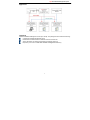
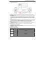
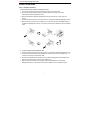
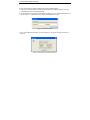
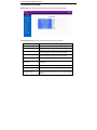
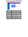
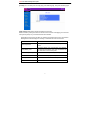
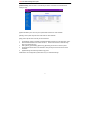
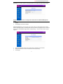
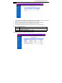
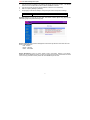
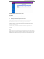
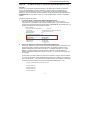
User’s Manual
PowerPanel
Shutdown Service
Graceful Shutdown and
Notification service to ensure
power protection of your computer
K01-SNMP004-00
TABLE OF CONTENTS
INTRODUCTION…………………………………...…………………
1
INSTALLATION GUIDE…………………………………...…………
5
CONFIGURATION GUIDE…………………...………………...……
9
Monitoring………………………………………………………….
9
Current Status..…………………………………………………
9
UPS Information...………………..…………………………….
10
Control….………………………………………………………….
11
UPS Control…..…………………………………………………
11
UPS Reboot……...………………..…………………………….
12
UPS Schedule…...………………..…………………………….
13
System……………………………. ……………………………….
14
System Time….…………………………………………………
14
User Accounts…..………………..…………………………….
14
Identification…………………………………………………….
15
Network………………………..…………………………………...
15
TCP/IP……………………..………..…………………………….
15
Access Control………………………………………………….
15
Trap Notification……………………………………………….
16
Events………..……………………………..………………………
17
Event Log…………………………………………………. …….
17
Event Generation………..……………………………………..
17
UPS Shutdown….………..……………………………………..
18
Summary…..……………………………..………………………...
19
Appendix 1. IP Address Settings of CyberPower Network
Management Card……………………………………
20
CyberPower Network Management System
INTRODUCTION
Overview
CyberPower Network Management Card allows for remote monitoring and control of a UPS on a
network. After installing the hardware and configuring an IP address, the user can access,
monitor, and control the UPS from anywhere in the world! Simply use a web browser such as
Internet Explorer or Firefox to access your UPS. Servers and workstations can be protected by
the UPS utilizing PowerPanel Shutdown Service software to gracefully shutdown when signaled
by the Network Management Card.
Features
z
z
z
z
z
z
z
z
z
z
z
Remote management and configuration of UPS via Web Browsers or NMS
Supports TCP/IP, UDP, SNMP, HTTP protocols
Automatic events notification via SNMP traps
Flexible Event Action setting
Auto-shutdown to protect servers and workstations from data loss due to power failure
Schedule shutdown/startup/reboot of UPS remotely
Event logging to trace UPS operation history
SNMP MIB provided
10Mbps Ethernet compatible
Quick installation and user friendly interface
Security management provided
System Requirements
A computer with a Windows Operating System (for optional Power Panel Shutdown
Service)
An Ethernet cable connection to an existing network
NMS (Network Management Station) compliant with SNMP (for optional NMS
management)
An RS232 cable to connect the CyberPower Network Management Card with the UPS
(For external Network Management Cards only)
1
CyberPower Network Management System
Application:
Unpacking
Inspect the Network Management Card upon receipt. The package should contain the following:
CyberPower Network Management Card
TM
PowerPanel Shutdown Service Software and user manuals CD
AC/DC transfomer for select UPS models and external cards only.
Expansion port cover for smart slot network management cards only.
2
CyberPower Network Management System
Description
a. Internal smart slot type
2
5
1
3
4
1) Signal connector provides a connection for communication between the UPS and the
Network Management Card
2) Reset Button is used to reset the card to default settings. When the Reset Button is pushed
for 3 seconds, all settings will reset to default values except for the IP address for Network
Management Card. When the Reset Button is pushed for more than 3 seconds, all settings
including the IP address for CyberPower Network Management Card will reset to default
values.
3) MSG Indicator indicates the status of connection between UPS and the Network
Management Card. This indicator light will flash when Network Management Card IS NOT
connected to the UPS.
4) LINK Indicator indicates the status of network connection. It illuminates when the Network
Management Card is connected to the network.
5) 10M Ethernet connector
Definitions for LED Indicators
Indicator
Mode
Condition
Off
The Network Management Card is connected to UPS
MSG
Flashing
No connection between the Network Management Card and
(Red)
the UPS
Off
The Network Management Card is not connected to the
LINK
Network
(Yellow)
On
The Network Management Card is connected to the Network
3
CyberPower Network Management System
b. External adapter type
1) Serial Port provides a connection for communication between the UPS and the Network
Management Card
2) Reset Button is used to reset the card to default settings. When the Reset Button is pushed
for 3 seconds, all settings will reset to default values except for the IP address for Network
Management Card. When the Reset Button is pushed for more than 3 seconds, all settings
including the IP address for CyberPower Network Management Card will reset to default
values.
3) DC power input allows input of power from the provided AC/DC transformer. The DC power
input is only used when the Network Management card is connected to select UPS models
that don’t supply power to the Network Management Card with the serial cable.
4) MSG Indicator indicates the status of connection between UPS and the Network
Management Card. This indicator light will flash when Network Management Card IS NOT
connected to the UPS.
5) PWR Indicator indicates the power is on or off. It illuminates when the Network
Management Card is powered ON.
6) LINK Indicator indicates the status of network connection. It illuminates when the Network
Management Card is connected to the network.
7) 10M Ethernet connector
Definitions for LED Indicators
Indicator
Mode
Condition
Off
The Network Management Card is connected to UPS
MSG
Flashing
No connection between the Network Management Card and
(Red)
the UPS
PWR
Off
The Network Management Card Power Is Off
(Green)
On
The Network Management Card Power Is On
Off
The Network Management Card is not connected to the
Network
LINK
(Yellow)
On
The Network Management Card is connected to the Network
On
The Network Management Card is connected to the Network
4
CyberPower Network Management System
INSTALLATION GUIDE
Step 1. Hardware Installation
a. Internal smart slot network management card
1. Turn off the UPS before removing the expansion port cover on the UPS..
2. Connect the internal data and power connector inside the expansion port to the
CyberPower Network Management Card.
3. Slide the CyberPower Network Management into the expansion port, and cover with
screws.
4. Connect the Ethernet cable to the LAN port of the CyberPower Network Management Card.
5. After the above procedures are complete, turn on the UPS and press the Reset Button on
the Network Management Card for 7 seconds to ensure the IP Address is set to the default
value.
a.
External network management card
1. Connect the Ethernet cable to the LAN port of the CyberPower Network Management Card.
2. Connect the CyberPower Network Management Card to the UPS communication port.
It
is optional to use the included serial cable.
3. Connect the supplied AC/DC transformer to the Network Management Card Adapter and
plug into the wall socket. (For select UPS models only).
4. After the above procedures are complete, press the Reset Button on the Network
Management Card for 7 seconds to ensure the IP Address is set to the default value.
5
CyberPower Network Management System
Step 2. Configure the IP address for the CyberPower Network Management Card.
Method 1 : Using the SNMP Card Configuration Tool
1. Install the SNMP Card Configuration Tool from the included CD.
Double click the “SNMP
Card Configuration Tool” installation file, “Setup.exe” from“\tools\wsnmpcfg” folder on the
CD-ROM drive.
2. After the installation completes run the “wsnmpcfg” program under “All Programs”->“SNMP
Card Configuration Tool”.
3. The main dialog of the “SNMP Card Configuration Tool” program is shown in Figure. 1. The
configuration tool will display all the SNMP cards present on the network.
The "Refresh"
button is used to search the entire local network for SNMP cards.
Figure 1. The main window of the “SNMP Card Configuration Tool” program.
4. Select the card and choose “Setup as selected” under the ”Tool” menu or double click the
SNMP card you want to configure.
5. You can modify the new IP, new subnet mask, and new gateway address using the IP or MAC
address in the SNMP card setting window, as shown in figure 2.
Figure 2. The SNMP card setting window.
6
CyberPower Network Management System
6. First, choose either IP or MAC address from the device address option.
7. Then click on each checkbox to modify the IP, subnet mask or gateway address. Enter the
new addresses into the corresponding fields.
8. You will need to input password for the SNMP card (Figure 3) in the authentication window, as
shown in figure 3.
*Default user name: cyber; Default password: cyber
Figure 3. Authentication window.
9. If you set IP address successfully, you will receive the IP set up OK message, as shown in
figure 4.
Figure 4. Setup IP Address successfully message.
7
CyberPower Network Management System
Method 2 : Using a command prompt
1. Obtain the MAC address on the label of the Network Management Card rear panel. Each
Management Card has a unique MAC address.
2. Use the ARP command to set the IP address. For example, to assign an IP address
192.168.20.240, in the same subnet as your computer, for the Network Management Card,
which has the MAC address 00-0c-15-00-00-01, type:
arp –s 192.168.20.240 00-0c-15-00-00-01
and press Enter.
3.To verify the setting, please type:
ping 192.168.20.240
and press Enter. If replies are received, your computer can communicate with the IP
address.
To find an IP address for the Network Management Card, please refer to Appendix 2.
If you want to assign an IP address, which is in a different subnet than your computer, for the
Network Management Card, you should followed Step 2, and then use the Browser Mode
Configuration to configure the IP address.
1. Open a Web Browser (Internet Explorer or Firefox)
2. Enter the IP Address which you previously configured.
3. On the login page enter the default username “cyber” and password “cyber”.
4. Click on TCP/IP Configuration on the Network menu to change the IP address.
‘Apply’ to save.
8
Click
CyberPower Network Management System
CONFIGURATION GUIDE
[Monitoring] menu contains [Current Status] page and [UPS Information] page
[Current Status] displays basic information about the current UPS status.
Status Field
Definition
Input Line Voltage
Shows the current input voltage of the utility power
Output Frequency
Displays the frequency of the utility power
Maximum Line Voltage
Identifies the highest voltage of the utility power input to
the UPS during the previous minute of operation.
Minimum Line Voltage
Identifies the lowest voltage of the utility power input to
the UPS during the previous minute of operation.
Output Voltage
Shows the output voltage of the UPS.
UPS Load
Shows the percent of battery capacity that is currently
being used.
Internal Temperature
Displays the internal operating temperature of the UPS.
Battery Capacity
Displays the current battery charge level.
On Battery Time
Displays the estimated battery run time available. This
display factors the UPS load and the current battery
capacity.
9
CyberPower Network Management System
[UPS Information] provides the technical specifications of your UPS.
Information
Description
Model Name
Displays the UPS’s model number
Voltage Rating
Identifies the current AC voltage to the UPS.
Working Frequency
Displays the current frequency of the UPS.
Power Rating
Displays the capacity of the UPS in VA.
Load Power
Identifies the capacity of the UPS in Watts.
Battery Voltage Rating
Displays the DC voltage of the battery.
Firmware Version
Shows the firmware version of the UPS.
Self-test Date
Displays the dates of the last self-tests.
Self-test Result
Displays the latest self-test result.
Please Note: [Self-test Date] and [Self-test Result] will only display when a self-test has been
set or performed.
10
CyberPower Network Management System
[Control] menu contains [UPS Control] page, [UPS Reboot] page, and [UPS Schedule] page.
[UPS Control] allows basic remote management of the UPS.
Select one test by clicking the button on the left of the command. Click [Apply] to run the test.
Click [Cancel] to stop any command that has been selected.
Please Note: If the UPS is shut OFF, the following commands will not work. The Network
Management Card will display the message: “Command fails. UPS is turned off.”
Commands
Definition
Auto Diagnostics
To verify that the UPS can function correctly in battery
mode.
Deep Battery Test
The Deep Battery Test will discharge the batteries.
The test will automatically stop when the batteries are
low, and return to AC-On line power.
Cancel Deep Battery Test
This command will stop the Deep Battery Test.
Put UPS to Sleep Mode
To turn off the UPS (no power output from the outlets).
Wake up UPS
To turn on the UPS when it is in sleep mode.
Turn Off UPS Buzzer
To turn the audible alarm of the UPS on/off.
11
CyberPower Network Management System
[UPS Reboot] allows advanced remote control of the UPS. Select one function by clicking its
button. Click [Apply] to begin the operation. Select [Cancel] to refresh the selection.
Note: The commands in [UPS Reboot] menu may be changed with the settings in the [UPS
Schedule] menu.
Commands
Definition
Reboot UPS Immediately
To turn the UPS off and then on again.
Delay 03 min(s) to Reboot
UPS
3 minutes is a default value. The user may select any
number between 1 and 99. The UPS will shut off and
wait the set amount of time before turning back on.
Cancel Reboot UPS
To stop the previous command “Delay 03 min(s) to
Reboot UPS.
Turn Off UPS Immediately
To turn the UPS off immediately.
Delay 03 min(s) to Turn Off
UPS
3 minutes is a default value. The user may select any
number between 1 and 99. The UPS will wait the set
amount of time before turning OFF.
Cancel Turn Off UPS
To stop the previous command “Delay 03 min(s) to
Turn Off UPS
Turn On UPS Immediately
To turn on UPS when it is turned off.
12
CyberPower Network Management System
[UPS Schedule]: Sets the UPS to automatically shutdown and restart at scheduled times,
weekly or daily.
[Special Shutdown]: The user may set a specific date and time for UPS shutdown.
[Weekly]: Set a specific day and time of the week for UPS shutdown.
[Daily]: Set a specific time of the day for UPS shutdown.
1.
2.
3.
4.
5.
Click [Special], [Daily] or [Weekly] scheduled shutdown features to enter each setup menu.
Enter the date and time to shut down the UPS. Please note that time is entered using
24Hr clock format (hh:mm).
Select [Never], [Immediately], [Same Day], [Next Day] for the UPS to recover power.
Click [Add] to add the item to the Schedule. Click [Cancel] to remove the item from the
Schedule.
Applied settings are listed in [Schedule Log] menu.
Please Note: The management system allows only 10 scheduled settings.
13
CyberPower Network Management System
[System] menu contains, [System Time] page [User Accounts] page and [Identification] page.
[System Time] allows users to configure the internal time of the Network Management
Card。
1. Enter the date and time and choose either Celsius or Fahrenheit for the temperature
display.
2. Click [Apply] to activate the settings.
[User Accounts] sets up user accounts. The system allows one administrator and two device
users to access the system. An administrator can access all of the management menus. A device
user can only access [Monitoring], [Events], and [Summary]. Only one user at a time may be
logged in.
1.
2.
3.
Select [Administrator] / [Device User] and enter the User Name and Password.
Retype the password to confirm the password was keyed properly.
Click [Apply].
14
CyberPower Network Management System
[Identification] assign the system’s name, contact, and location.
[Network] menu contains [TCP/IP] page, [Access Control] page and [Trap Notification] page.
[TCP/IP] This option allows you to enable or disable DHCP and define the IP Address, Subnet
Mask, Default Gateway and Web Port when DHCP is disabled.
Click [Apply] to activate the settings, click [Cancel] to revert to previous settings.
[Access Control] allows you to select the NMS defined by the IP settings that can use the
channel to control the system data access through SNMP.
15
CyberPower Network Management System
1.
2.
3.
4.
Input the manager IP address. This address will limit the access to the NMS. The default
value 0.0.0.0 or 255.255.255.255 which allows access for all NMS.
Input the community (functions as the password, maximum of 15 characters).
Select one of the permission options: [Read], [Write], or [Disable].
Click [Apply] to activate the settings, click [Cancel] to revert to previous inputs.
Definitions for Permission levels:
Read
The NMS can read data at any time, but can never write data.
Write
The NMS can read and write data at any time (provided there is not
another user logged in).
Disabled The NMS cannot use ‘Read’ or ‘Write’.
[Trap Notification]: Identify NMS that will receive traps.
16
CyberPower Network Management System
1.
2.
3.
4.
Input the receiver IP address. This address will identify the receiver of traps. The default
value 0.0.0.0 or 255.255.255.255 which defines all NMS as receivers.
Input the community (functions as the password, maximum of 15 characters).
Select one option [Enable] or [Disable].
Click [Apply] to activate the settings, click [Cancel] to revert to the previous settings.
Enable
Disable
The trap will be generated.
The trap will not be generated.
[Events] displays an event log for the UPS. The section contains [Event Log] page [Event
Generation] page and [UPS Shutdown] page.
[Event Log] displays the Network Management Card events by date and time. More than 200
events can be displayed.
Red:Severe
Brown:Warning
Black:Information
[Event Generation]: There are three severity levels, Information, Warning, and Severe.
Please refer to their definitions below. The User can assign which severity levels will be recorded
in the event log and which severity levels will cause SNMP traps to be sent.
17
CyberPower Network Management System
Information indicates an event that requires no action.
Warning indicates an event that does not require immediate attention, but this condition should
be monitored.
Severe indicates an event that requires immediate attention.
1.
2.
Determine the severity levels and click the option buttons.
Click [Apply] to activate the settings.
[UPS Shutdown]: Configures the UPS shutdown and PC safe shutdown times.
1. Low-Battery Duration: Time from a Low-Battery signal until load is shutdown.
2. Maximum Shutdown Time: The maximum time the UPS will wait before it shuts down in
response to a turnoff command.
3. Shutdown Delay: Time the UPS will wait before it shuts down in response to a turnoff
command.
Note:
In order to have the PCs connected to the UPS so that they can be shut down safely, add the IP
address of the PCs receivers into Trap Notification. (Reference to Page14.) Install “Power Panel
Shutdown Service” software, and then assign the IP addresses to “Network Management Card”
18
CyberPower Network Management System
[Summary] Displays the current UPS and CyberPower Network Management Card Status.
19
CyberPower Network Management System
Appendix 1 IP Address Settings of CyberPower Network Management Card
Overview
All devices on a computer network need to have an IP address. Each device’s IP address is
unique. The same address cannot be used twice. In order to assign an IP address to the
CyberPower Network Management Card, you must determine the range of the available IP
addresses, and then choose an unused IP address to assign to the Network Management Card.
PLEASE NOTE: You may need to contact your network administrator to obtain an available IP
address.
Procedures to find an IP address:
1. Locate the subnet of CyberPower Network Management Card.
One way to determine the range of possible IP addresses is to view the network
configuration on a workstation. Click on [Start] and select [Run]. Type “command” into the
open box and click [OK]. At the command prompt type “ipconfig /all” and press [Enter]. The
computer will display network information as below:
Ethernet adapter
Connection-specific DNS Suffix…………: xxxx.com
Description……………………: D-Link DE220 ISA PnP LAN adapter
Physical Address…………….: 00-80-C8-DA-7A-C0
DHCP Enabled……………....: Yes
Autoconfiguration Enabled ...: Yes
IP Address…………………..: 192.168.20.102
Subnet Mask………………..: 255.255.255.0
Default Gateway……..……...: 192.168.20.1
DHCP Server…………..…….: 192.168.20.1
DNS Servers…………………: 211.20.71.202
168.95.1.1
2. Select an IP Address for CyberPower Network Management Card
Verify the IP Addresses for the computer and the Network Management Card belong to the
same subnet. Refer to the above network information, the possible IP Address for the
Network Management Card could be 192.168.20.* (* hereafter represents any number
between 1 and 255). Similarly, if the Subnet Mask is 255.255.0.0, the IP Address for
Network Management Card could be set up as 192.168.*.* to reach the same subnet with
the computer.
To verify there is no other equipment connected to the network using the same IP Address,
run “Ping 192.168.20.240” at the DOS Mode prompt when the IP Address you would like to
set is 192.168.20.240. If the response is presented as below, the IP address is most likely
not used and may be available for the CyberPower Network Management Card.
Pinging 192.168.20.240 with 32 bytes of data:
Request timed out.
Request timed out.
Request timed out.
Request timed out.
20
CyberPower Network Management System
If the response is shown as below, the IP address is in use. Try another IP address until an
available address is found.
Pinging 192.168.20.240 with 32 bytes of data:
Reply from 192.168.20.240: bytes=32 time<10ms TTL=64
Reply from 192.168.20.240: bytes=32 time<10ms TTL=64
Reply from 192.168.20.240: bytes=32 time<10ms TTL=64
Reply from 192.168.20.240: bytes=32 time<10ms TTL=64
21