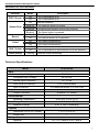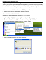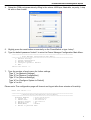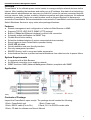
1
PowerSwitch Network Management System Overview ‘PowerSwitch’ is the ultimate power control center to manage multiple network devices via the Internet. After installing the hardware and setting up an IP address, this state-of-art technology allows network administrators an easy way to control AC power for various connected devices, such as servers, hubs, routers, modems, telephone systems and other equipment. No software installation is needed. Simply use a web browser such as Internet Explorer or Netscape to access the PowerSwitch. Servers/workstations connected to PowerSwitch could be installed with Switch Shutdown Service to enjoy extra value-packaged features. Features z z z z z z z z z z z z Remote management and configuration of outlet via Web Browser or NMS Supports TCP/IP, UDP, DHCP, SNMP, HTTP protocol Built-in 10Mbps fast Ethernet interface for direct LAN connection Automatic events notification via SNMP Trap Flexible Event Action setting Schedule shutdown/startup of various connected devices remotely. Event logging to trace PowerSwitch operation history SNMP MIB provided Quick installation and user friendly interface Security management provided. EMI/RFI filtering, built-in surge and spike suppression Auto-shutdown service to protect servers/workstations from data loss due to power failure. System Requirements z z z A computer with a Web Browser An Ethernet connection to an existing network SNMP functions: NMS (Network Management Station) compliant with SNMP Application *Daisy-Chained function is optional. Contents of Package Inspect the PowerSwitch upon receipt. The package should contain the following: 1 Each: PowerSwitch unit 1 Each; Power cord 1 Each; RS232 cable (Pin-to-Pin) 2 Each; RJ11 to RS232 combo cable 1 Each; CD disk for software and User’s Manual 1 PowerSwitch Network Management System Basic Operation FRONT PANEL DESCRIPTION 1. On/Off Switch: To turn on/off the PowerSwitch. 2. PWR Indicator indicates the status of on/off of the PowerSwitch. 3. Status Indicator indicates the status of PowerSwitch. 4. Daisy Chain connector: provides connection with multiple PowerSwitch client units.(Option) 5. Manual Button & Outlet Buttons: To switch on/off the outlets. Press and hold the Manual Button + the Outlet button to toggle on/off. 6. Manual Indicator: indicates when the Manual Button is pressed. 7. Outlet Indicator: indicates the on/off status of each outlet. 8. Reset Button is used to reset the settings. · To enable COM Port settings, slightly press the Reset Button that the Status Indicator will blink once. · To reset all settings to default value except for the IP address, press the Reset Button for 4 seconds that the Status Indicator will blink for 2 times continuously. · To reset all settings to default value, press the Reset Button for 6 seconds that the Status Indicator will blink for 3 times continuously and then you will hear a short beep in the end. 9. LAN Port: 10Base-T Ethernet connector 10. Link Indicator indicates the status of connecting to the network. This LED is illuminated when PowerSwitch is connected to the network. 11. Tx/Rx Indicator: This LED is illuminated when data transmitting. 12. Communications Port provides a Serial connection and communication path between the PowerSwitch and the Local computer. REAR PANEL DESCRIPTION 13. RJ-11 communication Port: Provides communication of the Switch Shutdown Service. 14. AC output outlets 15. Circuit Breaker: Reset for Overload protection. 16. AC input 2 PowerSwitch Network Management System Definitions for LED Indicators Indicator Mode PWR (Green) Status (Red) Off The PowerSwitch is off. On The PowerSwitch is on. Off Normal condition Solid On The Network setting is invalid. Flashing Temperature/Humidity exceed user settings Blinking The Reset button is pressed. Manual Outlet LINK (Yellow) Tx/Rx (Green) Description On The Manual Button is pressed. Off The Manual Button is not pressed. On The outlet is switched on Off The outlet is switched off Off Ethernet disconnect On The PowerSwitch is disconnected from the Network. Flashing Network Data transmitting Technical Specifications Model CPS120CSA Input Normal Input Voltage 100-120 Vac Acceptable Input Voltage 90-150 Vac Normal Input Frequency 50 – 60 Hz Over-current Protection 15-A Circuit Breaker Input Connector 10 ft attached NEMA 5-15 Line Cord Output Output Connector 8 NEMA 5-15 Outlets Environmental o o Operating Temperature 32 to 158 F (0 to 70 C) Storage Temperature 5 to 158 F (-15 to 70 C) Relative Humidity 0-95 %, Non-Condensing o o Physical Dimension (H x W x D, inches) Weight (lbs) 1.73 x 17.04 x 4.6 7 Safety Approval UL; FCC Class B; DOC Class B 3 PowerSwitch Network Management System INSTALLATION GUIDE Step 1. Hardware Installation 1. Connect the Ethernet cable to the LAN port of the PowerSwitch. 2. After the above procedures are completed, please turn on the PowerSwitch. To reset the IP Address to default value, press the Reset Button on the PowerSwitch front panel continuously for 6 seconds that the Status Indicator will blink for 3 times continuously and then you will hear a short beep in the end. 3. Power off the PowerSwitch and then power back on. Step 2. Setup the IP address for the PowerSwitch. THREE OPTIONS: Option 1: Setup the IP address via DOS 1. If you have DHCP server, the DHCP server will give you the MAC address to IP mappings. Just open your Web Browser with the IP provided by DHCP server. 2. If you don’t have DHCP server, obtain the MAC address for the PowerSiwtch. (Each PowerSwitch has a unique MAC address printed on the label on rear panel.). 3. For example: to assign an IP address 192.168.20.240 which is in the same subnet as your computer with PowerSwitch, which has the MAC address for example 00-0c-15-00-01-23: Open a DOS prompt and run an ARP command: Example: arp –s 192.168.20.240 00-0c-15-00-01-23 and press Enter to set the IP address. 4. To verify the setting, run a ping command: ping 192.168.20.240 If you receive a reply, the IP address has been set. To find an IP address for the PowerSwitch, please refer to Appendix 2. If you want to assign an IP address which is in a different subnet to your computer, you should follow Step 2. Then you can enter the Browser Mode Configuration and enter the correct IP address and subnet for its final location. 1. Open your Web Browser (Internet Explorer or Netscape) 2. Enter the IP Address which you assigned in Step 2, Option 1 above. 3. On the login page, enter the current password. The default username is “admin” and the default password is “admin”. 4. Select Network and click on TCP/IP configuration to change the IP address. Click Apply to save the changes. 4 PowerSwitch Network Management System Option 2: Setup the IP address through Network Route When you first time use the PowerSwitch, your workstation is normally not able to communicate to PowerSwitch because they are not in the same IP subnet. You may use “route add” command to manipulate the network routing table in your workstation to implement the configuration. 1. Please procure a workstation and set up the TCP/IP protocol if necessary. 2. To add a routing condition, please enter the below command. Route add 192.168.20.177 61.222.33.225 ( Assumption: the IP address of the workstation is 61.222.33.225.) Option 3: Setup the IP address through Communications Port 1. Connect the PowerSwitch and the local computer via the included RS232 cable. 2. From the workstation running MS windows, click on the Hyper Terminal of the communications from the accessory programs as below showed. 3. Enter a name and choose an icon for the connection. 5 PowerSwitch Network Management System 4. Setup the COM port parameters by filling in the values: 4800 bps, 8data bits, no parity, 1 stop bit and no flow control. 5. 6. Slightly press the reset button momentarily on the PowerSwitch or type “setup”. Type the default password “admin” to enter the Power Manager Configuration Main Menu. ======================================================================== [ Power Manager Configuration Main Menu ] ======================================================================== 1. Network Settings 2. System Configuration 3. Account Settings 4. Configure System to Default e. Exit Enter Your Choice --> 7. Type the number of each menu for further settings Type “1” for [Network Settings] Type “2” for [System Configuration] Type “3” for [Account Settings] Type “4” for [Configure System to Default] Type “e” to exit Please note: The configuration page will timeout and logout after three minutes of inactivity. Enter Your Choice -->1 ======================================================================== [ Network Group Configuration Utility Menu ] ======================================================================== Ethernet Address : 00-0c-15-00-02-00 1. System IP : 192.168.20.177 2. Subnet Mask : 255.255.255.0 3. Default Gateway : 192.168.20.1 4. Web/Http Port : 80 5. BOOTP(DHCP) : Enable 0. Return to previous menu 6 PowerSwitch Network Management System Enter Your Choice -->2 ======================================================================== [ System Group Configuration Utility Menu ] ======================================================================== 1. Internal Date(mm/dd/yyyy) : 01/01/2000 2. Internal Time(hh:mm:ss) : 00:32:01 3. System Name : Power Manager 4. System Contact : Administrator 5. System Location : Server Room 0. Return to previous menu Enter Your Choice -->3 ======================================================================== [ Account Group Configuration Utility Menu ] ======================================================================== 1. Web Administrator User Name : admin 2. Web Administrator User Password : admin 3. Web Device User Name : device 4. Web Device User Password : device 5. COM Port Configuration Password : admin 0. Return to previous menu Enter Your Choice -->4 ======================================================================== [ Default Group Configuration Utility Menu ] ======================================================================== 1. Reset System to Default 2. Reset System to Default Except IP 0. Return to previous menu Enter Your Choice -->e ============== CONFIGURATION SYSTEM LOGOUT ============== You already exited Configuration Utility System. Please relogin to setup system again. ========================================================= Type "setup" to relogin >> 7 PowerSwitch Network Management System CONFIGURATION GUIDE [Outlets] menu contains [Control], [Current Status], and [Configuration] [Control] allows switching on/off the outlets immediately or after a specific duration. Click the Outlet number and the Action Type and then click [Apply] for operation. A selected button will turn a green color. Only by clicking [Apply] will the selected command become active. Select [Cancel] to refresh the selection. NOTE: When turning on/off at a duration time is applied, the [Outlet control] page will turn to [Pending Log] page automatically. [Current Status] displays the power status of each outlet. [Configuration] allows configuration of the duration time to turn on/off the outlets and enable or disable of manual switch on/off. 1. 2. 3. 4. Select the outlet number to enter its sub menu. Give name to the device. (Optional settings) Enter the duration time. Please note that time is entered using 24Hr clock format (hh:mm:ss). Enable or disable the manual switching on/off. When manual disabled, the outlet can not be switched on or off from the front panel. 5. Click [Apply] for operation. Select [Cancel] to refresh the settings. 8 PowerSwitch Network Management System [Logs] displays an event log for the PowerSwitch. The section contains [Pending Log], [Schedule], and [Event Configuration]. [Pending Log]: displays the current pending commands. [Schedule]: The user may set the outlets on the PowerSwitch to automatically shutdown and restart at consistent times, daily, weekly or once. [Daily]: a specific time of the day [Weekly]: a specific day and time of the week [Once]: a specific date and time 1. Click on “Outlet Schedule” to enter the sub menu [Schedule Time Table] for adding a new schedule. 2. Select [Daily], [Weekly] or [Once] by clicking its button and then enter the time. A selected button will turn a green color. Please note that time is entered using 24Hr clock format (hh:mm). 3. Click [Apply] to enter [Outlet Selection]. 4. Select the outlet number to be applied to the schedule. A selected button will turn a green color. 5. Click [Apply] to active the settings. Click [Cancel] to refresh the settings. The applied scheduled settings are listed in [Schedule] menu. Please Note: The management system allows only 10 scheduled settings. [Event Log]: displays the PowerSwitch events by date and time. More than 200 events can be displayed. 9 PowerSwitch Network Management System [System] menu contains [System Time], [User Accounts], and [Identification]. [System Time] serves to setup the PowerSwitch system’s Date and Time. Click [Apply] to active the settings. Click [Cancel] to refresh the settings. [User Accounts] serves to setup user accounts. The system allows one administrator and one device user to access the system. The administrator can access all of the management menus. The device user can access only [Outlet], [Logs], and [Summary] menus. 1. Select [Administrator] / [Device User] and enter the User Name and Password. The username and the password must be less than 15 characters. The default username is admin and the password is admin. 2. Click [Apply]. 3. Type the password to confirm the password was keyed properly. [Identification] Assign the PowerSwitch system’s name, contact, and location. 10 PowerSwitch Network Management System [Network] menu contains [TCP/IP], [Access Control] and [Trap Notification]. [TCP/IP] displays IP Address, Subnet Mask, Default Gateway, and Web/Http Port as well as enable or disable the BOOTP/DHCP configuration. Click [Apply] to activate the settings, click [Cancel] to revert to previous inputs. [Access Control] serves to control access to the NMS. Limit system data access through SNMP. 1. Input the manager IP address. This address will limit the access to the NMS. The default value 0.0.0.0 or 255.255.255.255 allows access for all NMS. 2. Input the community (functioned as password, maximum of 15 characters). 3. Select one of the permission options: [Read], [Write], or [Disable]. 4. Click [Apply] to activate the settings, click [Cancel] to revert to previous inputs. Definitions for Permission levels: Read The NMS can read data at any time, but can never write data. Write The NMS can read and write data at any time (provided there is not another user logged in). Disabled The NMS cannot use ‘Read’ or ‘Write’. [Trap Notification]: Identify NMS that will receive traps. 1. Click on “Trap Receiver” to enter the [Trap Configuration] page 2. Input the receiver’s name and IP address. This address will identify the receiver of traps. The default value 0.0.0.0 or 255.255.255.255 defines all NMS as receivers. 3. Input the community (functioned as password, maximum of 15 characters). 4. Click [Apply] to activate the settings, click [Cancel] to revert to the previous settings. 5. The applied Trap Receiver will be listed on the [Trap Notification] page. You could click a Trap Receiver to change the name, the IP, the community and the status including [Enable], [Disable], and [Delete]. Enable: The trap will be generated. Disable: The trap will not be generated. Delete: The trap receiver will not remain on the list. 11 PowerSwitch Network Management System [Configure] menu contains [Event Generation] page and [Environment] page. [Event Generaton]: There are three severity levels, Information, Warning, and Severe. Please refer to their definitions below. You can assign which severity levels will be recorded in the event log and which severity levels will cause SNMP traps to be sent. Information: an event that requires no action. Warning: an event that does not require immediate attention, but the condition should be monitored. Severe: an event that requires immediate attention. 1. Determine the severity levels and click the option buttons. 2. Enter the time the signal is to be sent. The default value is 3 minutes. The time must be less than 99 minutes and greater than 1 minute. 3. Click [Apply] to activate the settings. [Environment]: To set up the temperature and humidity range with beeper warning or none and control the status (ON/OFF) of each outlet by different environment set. 12 PowerSwitch Network Management System [Summary]: Displays the current PowerSwitch Status. 13 PowerSwitch Network Management System Appendix 1: IP Address Settings of PowerSwitch Overview All devices on a computer network need to have an IP address. Each device’s IP address is unique. The same address cannot be used twice. In order to assign an IP address to the PowerSwitch, first, you must determine the range of the IP address, and then you choose a number that is in this range. It is essential to use an IP address that is not currently in use. PLEASE NOTE: You may need to contact your network administrator. He/She will assign the IP addresses for your Management Card. Procedures to find an IP address: 1. Locate the subnet of PowerSwitch. One way to determine the range of possible IP addresses is to access the network configuration of a computer connected to the network. For example; using a MS Windows© operating system, click on [Start] and select [Run]. Type “command” into the open box and click [OK]. At the DOS Mode Prompt type “ipconfig /all” and press [Enter]. The computer will display network information as below: Ethernet adapter Connection-specific DNS Suffix……: Description………………………………………………..…: Physical Address……………………………………..: DHCP Enabled……………………………..………....: Autoconfiguration Enabled ….....: IP Address…………………………………………...…..: Subnet Mask……………………………………………....: Default Gateway……..………………………....: DHCP Server…………..……………………………..….: DNS Servers…………………………………………..………: xxxx.com D-Link DE220 ISA PnP LAN adapter 00-80-C8-DA-7A-C0 Yes Yes 192.168.20.102 255.255.255.0 192.168.20.1 192.168.20.1 211.20.71.202 168.95.1.1 2. Select an IP Address for PowerSwitch Make sure the IP Addresses for the computer and the PowerSwitch belong to the same subnet. Refer to the above network information, a possible IP Address for PowerSwitch could be 192.168.20.* (* hereafter represents any number between 1 and 255). Similarly, if the Subnet Mask is 255.255.0.0, the IP Address for PowerSwitch could be set up as 192.168.*.*. To ensure there is no other equipment connected to the network using the same IP Address you choose, you run a ping command “Ping 192.168.20.240” in MS-DOS mode when the IP Address you would like to set is 192.168.20.240. If the response is presented as below, the IP address is not used and available for PowerSwitch. Pinging Request Request Request Request 192.168.20.240 with 32 bytes of data: timed out. timed out. timed out. timed out. If the response is shown as below, the IP address is already in use by another device. Try another IP address until an available address is found. Pinging 192.168.20.240 with 32 bytes of data: Reply from 192.168.20.240: bytes=32 time<10ms Reply from 192.168.20.240: bytes=32 time<10ms Reply from 192.168.20.240: bytes=32 time<10ms Reply from 192.168.20.240: bytes=32 time<10ms TTL=64 TTL=64 TTL=64 TTL=64 *Specifications subject to change and without notice. 14