1
RLM R6+ Performer
Owners manual
R9010270
R5976816/03
02/06/2006
Barco nv Events
Noordlaan 5, B-8520 Kuurne
Phone: +32 56.36.89.70
Fax: +32 56.36.88.24
E-mail: [email protected]
Visit us at the web: www.barco.com
Printed in Taiwan
Changes
Barco provides this manual ’as is’ without warranty of any kind, either expressed or implied, including but not limited to the implied warranties or merchantability and fitness for a particular purpose. Barco may make improvements and/or changes to the product(s) and/or the
program(s) described in this publication at any time without notice.
This publication could contain technical inaccuracies or typographical errors. Changes are periodically made to the information in this
publication; these changes are incorporated in new editions of this publication.
Copyright ©
All rights reserved. No part of this document may be copied, reproduced or translated. It shall not otherwise be recorded, transmitted or
stored in a retrieval system without the prior written consent of Barco.
Guarantee and Compensation
Barco provides a guarantee relating to perfect manufacturing as part of the legally stipulated terms of guarantee. On receipt, the purchaser
must immediately inspect all delivered goods for damage incurred during transport, as well as for material and manufacturing faults Barco
must be informed immediately in writing of any complaints.
The period of guarantee begins on the date of transfer of risks, in the case of special systems and software on the date of commissioning,
at latest 30 days after the transfer of risks. In the event of justified notice of complaint, Barco can repair the fault or provide a replacement
at its own discretion within an appropriate period. If this measure proves to be impossible or unsuccessful, the purchaser can demand a
reduction in the purchase price or cancellation of the contract. All other claims, in particular those relating to compensation for direct or
indirect damage, and also damage attributed to the operation of software as well as to other services provided by Barco, being a component
of the system or independent service, will be deemed invalid provided the damage is not proven to be attributed to the absence of properties
guaranteed in writing or due to the intent or gross negligence or part of Barco.
If the purchaser or a third party carries out modifications or repairs on goods delivered by Barco, or if the goods are handled incorrectly,
in particular if the systems are commissioned operated incorrectly or if, after the transfer of risks, the goods are subject to influences not
agreed upon in the contract, all guarantee claims of the purchaser will be rendered invalid. Not included in the guarantee coverage are
system failures which are attributed to programs or special electronic circuitry provided by the purchaser, e.g. interfaces. Normal wear as
well as normal maintenance are not subject to the guarantee provided by Barco either.
The environmental conditions as well as the servicing and maintenance regulations specified in the this manual must be complied with by
the customer.
Trademarks
Brand and product names mentioned in this manual may be trademarks, registered trademarks or copyrights of their respective holders.
All brand and product names mentioned in this manual serve as comments or examples and are not to be understood as advertising for
the products or their manufactures.
Table of contents
TABLE OF CONTENTS
1. Packaging and Dimensions . . . . . . . . . . . . . . . . . . . . . . . . . . . . . . . . . . . . . . . . . . . . . . . . . . . . . . . . . . . . . . . . . . . . . . . . . . . . . . . . . . . . . . 5
1.1
1.2
1.3
Box content . . . . . . . . . . . . . . . . . . . . . . . . . . . . . . . . . . . . . . . . . . . . . . . . . . . . . . . . . . . . . . . . . . . . . . . . . . . . . . . . . . . . . . . . . . . . . . . . . . . . . . . . . . . . . . . . . . . . . . . . . . . 5
Projector Packaging . . . . . . . . . . . . . . . . . . . . . . . . . . . . . . . . . . . . . . . . . . . . . . . . . . . . . . . . . . . . . . . . . . . . . . . . . . . . . . . . . . . . . . . . . . . . . . . . . . . . . . . . . . . . . . . . . . 5
Dimensions . . . . . . . . . . . . . . . . . . . . . . . . . . . . . . . . . . . . . . . . . . . . . . . . . . . . . . . . . . . . . . . . . . . . . . . . . . . . . . . . . . . . . . . . . . . . . . . . . . . . . . . . . . . . . . . . . . . . . . . . . . . 7
2. Installation Guidelines. . . . . . . . . . . . . . . . . . . . . . . . . . . . . . . . . . . . . . . . . . . . . . . . . . . . . . . . . . . . . . . . . . . . . . . . . . . . . . . . . . . . . . . . . . . . 11
2.1
2.2
2.3
General . . . . . . . . . . . . . . . . . . . . . . . . . . . . . . . . . . . . . . . . . . . . . . . . . . . . . . . . . . . . . . . . . . . . . . . . . . . . . . . . . . . . . . . . . . . . . . . . . . . . . . . . . . . . . . . . . . . . . . . . . . . . . . 11
Projector Configuration . . . . . . . . . . . . . . . . . . . . . . . . . . . . . . . . . . . . . . . . . . . . . . . . . . . . . . . . . . . . . . . . . . . . . . . . . . . . . . . . . . . . . . . . . . . . . . . . . . . . . . . . . . . . . . 12
Lenses . . . . . . . . . . . . . . . . . . . . . . . . . . . . . . . . . . . . . . . . . . . . . . . . . . . . . . . . . . . . . . . . . . . . . . . . . . . . . . . . . . . . . . . . . . . . . . . . . . . . . . . . . . . . . . . . . . . . . . . . . . . . . . . 14
2.3.1 Lenses. . . . . . . . . . . . . . . . . . . . . . . . . . . . . . . . . . . . . . . . . . . . . . . . . . . . . . . . . . . . . . . . . . . . . . . . . . . . . . . . . . . . . . . . . . . . . . . . . . . . . . . . . . . . . . . . . . . . . . . . . 14
2.3.2 Lens formulas . . . . . . . . . . . . . . . . . . . . . . . . . . . . . . . . . . . . . . . . . . . . . . . . . . . . . . . . . . . . . . . . . . . . . . . . . . . . . . . . . . . . . . . . . . . . . . . . . . . . . . . . . . . . . . . . . 15
2.3.3 Lens installation . . . . . . . . . . . . . . . . . . . . . . . . . . . . . . . . . . . . . . . . . . . . . . . . . . . . . . . . . . . . . . . . . . . . . . . . . . . . . . . . . . . . . . . . . . . . . . . . . . . . . . . . . . . . . . . 15
2.3.4 Cleaning the lens . . . . . . . . . . . . . . . . . . . . . . . . . . . . . . . . . . . . . . . . . . . . . . . . . . . . . . . . . . . . . . . . . . . . . . . . . . . . . . . . . . . . . . . . . . . . . . . . . . . . . . . . . . . . . 16
2.4 Battery Insertion in the Remote Control . . . . . . . . . . . . . . . . . . . . . . . . . . . . . . . . . . . . . . . . . . . . . . . . . . . . . . . . . . . . . . . . . . . . . . . . . . . . . . . . . . . . . . . . . . . . 16
2.5 Stacking projectors . . . . . . . . . . . . . . . . . . . . . . . . . . . . . . . . . . . . . . . . . . . . . . . . . . . . . . . . . . . . . . . . . . . . . . . . . . . . . . . . . . . . . . . . . . . . . . . . . . . . . . . . . . . . . . . . . . 17
2.6 Rigging points and accessories . . . . . . . . . . . . . . . . . . . . . . . . . . . . . . . . . . . . . . . . . . . . . . . . . . . . . . . . . . . . . . . . . . . . . . . . . . . . . . . . . . . . . . . . . . . . . . . . . . . . . 19
2.6.1 Overview . . . . . . . . . . . . . . . . . . . . . . . . . . . . . . . . . . . . . . . . . . . . . . . . . . . . . . . . . . . . . . . . . . . . . . . . . . . . . . . . . . . . . . . . . . . . . . . . . . . . . . . . . . . . . . . . . . . . . . 19
2.6.2 Mounting the clamps. . . . . . . . . . . . . . . . . . . . . . . . . . . . . . . . . . . . . . . . . . . . . . . . . . . . . . . . . . . . . . . . . . . . . . . . . . . . . . . . . . . . . . . . . . . . . . . . . . . . . . . . . . 19
3. Connections. . . . . . . . . . . . . . . . . . . . . . . . . . . . . . . . . . . . . . . . . . . . . . . . . . . . . . . . . . . . . . . . . . . . . . . . . . . . . . . . . . . . . . . . . . . . . . . . . . . . . . . . 21
3.1
3.2
Power connection . . . . . . . . . . . . . . . . . . . . . . . . . . . . . . . . . . . . . . . . . . . . . . . . . . . . . . . . . . . . . . . . . . . . . . . . . . . . . . . . . . . . . . . . . . . . . . . . . . . . . . . . . . . . . . . . . . . 21
Input Source Connections. . . . . . . . . . . . . . . . . . . . . . . . . . . . . . . . . . . . . . . . . . . . . . . . . . . . . . . . . . . . . . . . . . . . . . . . . . . . . . . . . . . . . . . . . . . . . . . . . . . . . . . . . . . 22
3.2.1 Input section. . . . . . . . . . . . . . . . . . . . . . . . . . . . . . . . . . . . . . . . . . . . . . . . . . . . . . . . . . . . . . . . . . . . . . . . . . . . . . . . . . . . . . . . . . . . . . . . . . . . . . . . . . . . . . . . . . . 22
3.2.2 Input facilities. . . . . . . . . . . . . . . . . . . . . . . . . . . . . . . . . . . . . . . . . . . . . . . . . . . . . . . . . . . . . . . . . . . . . . . . . . . . . . . . . . . . . . . . . . . . . . . . . . . . . . . . . . . . . . . . . . 22
3.3 5-Cable input . . . . . . . . . . . . . . . . . . . . . . . . . . . . . . . . . . . . . . . . . . . . . . . . . . . . . . . . . . . . . . . . . . . . . . . . . . . . . . . . . . . . . . . . . . . . . . . . . . . . . . . . . . . . . . . . . . . . . . . . 23
3.4 Composite Video Input . . . . . . . . . . . . . . . . . . . . . . . . . . . . . . . . . . . . . . . . . . . . . . . . . . . . . . . . . . . . . . . . . . . . . . . . . . . . . . . . . . . . . . . . . . . . . . . . . . . . . . . . . . . . . . 25
3.5 S-Video input . . . . . . . . . . . . . . . . . . . . . . . . . . . . . . . . . . . . . . . . . . . . . . . . . . . . . . . . . . . . . . . . . . . . . . . . . . . . . . . . . . . . . . . . . . . . . . . . . . . . . . . . . . . . . . . . . . . . . . . . 26
3.6 Digital Visual Interface (DVI) input . . . . . . . . . . . . . . . . . . . . . . . . . . . . . . . . . . . . . . . . . . . . . . . . . . . . . . . . . . . . . . . . . . . . . . . . . . . . . . . . . . . . . . . . . . . . . . . . . . 27
3.7 Computer input (RGB analog) . . . . . . . . . . . . . . . . . . . . . . . . . . . . . . . . . . . . . . . . . . . . . . . . . . . . . . . . . . . . . . . . . . . . . . . . . . . . . . . . . . . . . . . . . . . . . . . . . . . . . . 29
3.8 SDI or HDSDI input. . . . . . . . . . . . . . . . . . . . . . . . . . . . . . . . . . . . . . . . . . . . . . . . . . . . . . . . . . . . . . . . . . . . . . . . . . . . . . . . . . . . . . . . . . . . . . . . . . . . . . . . . . . . . . . . . . 29
3.9 Communication connection . . . . . . . . . . . . . . . . . . . . . . . . . . . . . . . . . . . . . . . . . . . . . . . . . . . . . . . . . . . . . . . . . . . . . . . . . . . . . . . . . . . . . . . . . . . . . . . . . . . . . . . . . 30
3.9.1 RS232 IN connection . . . . . . . . . . . . . . . . . . . . . . . . . . . . . . . . . . . . . . . . . . . . . . . . . . . . . . . . . . . . . . . . . . . . . . . . . . . . . . . . . . . . . . . . . . . . . . . . . . . . . . . . . 30
3.9.2 Wireless receiver. . . . . . . . . . . . . . . . . . . . . . . . . . . . . . . . . . . . . . . . . . . . . . . . . . . . . . . . . . . . . . . . . . . . . . . . . . . . . . . . . . . . . . . . . . . . . . . . . . . . . . . . . . . . . . 31
3.10 Extended configuration . . . . . . . . . . . . . . . . . . . . . . . . . . . . . . . . . . . . . . . . . . . . . . . . . . . . . . . . . . . . . . . . . . . . . . . . . . . . . . . . . . . . . . . . . . . . . . . . . . . . . . . . . . . . . . 32
3.10.1 Introduction. . . . . . . . . . . . . . . . . . . . . . . . . . . . . . . . . . . . . . . . . . . . . . . . . . . . . . . . . . . . . . . . . . . . . . . . . . . . . . . . . . . . . . . . . . . . . . . . . . . . . . . . . . . . . . . . . . . . 32
3.10.2 5-cable extended configuration. . . . . . . . . . . . . . . . . . . . . . . . . . . . . . . . . . . . . . . . . . . . . . . . . . . . . . . . . . . . . . . . . . . . . . . . . . . . . . . . . . . . . . . . . . . . . . . 32
3.10.3 S-Video extended configuration . . . . . . . . . . . . . . . . . . . . . . . . . . . . . . . . . . . . . . . . . . . . . . . . . . . . . . . . . . . . . . . . . . . . . . . . . . . . . . . . . . . . . . . . . . . . . . 33
3.10.4 Summarizing . . . . . . . . . . . . . . . . . . . . . . . . . . . . . . . . . . . . . . . . . . . . . . . . . . . . . . . . . . . . . . . . . . . . . . . . . . . . . . . . . . . . . . . . . . . . . . . . . . . . . . . . . . . . . . . . . . 34
4. Getting Started. . . . . . . . . . . . . . . . . . . . . . . . . . . . . . . . . . . . . . . . . . . . . . . . . . . . . . . . . . . . . . . . . . . . . . . . . . . . . . . . . . . . . . . . . . . . . . . . . . . . . 35
4.1
4.2
4.3
4.4
4.5
4.6
4.7
4.8
Terminology overview . . . . . . . . . . . . . . . . . . . . . . . . . . . . . . . . . . . . . . . . . . . . . . . . . . . . . . . . . . . . . . . . . . . . . . . . . . . . . . . . . . . . . . . . . . . . . . . . . . . . . . . . . . . . . . . 35
Switching on . . . . . . . . . . . . . . . . . . . . . . . . . . . . . . . . . . . . . . . . . . . . . . . . . . . . . . . . . . . . . . . . . . . . . . . . . . . . . . . . . . . . . . . . . . . . . . . . . . . . . . . . . . . . . . . . . . . . . . . . . 37
Lamp runtime . . . . . . . . . . . . . . . . . . . . . . . . . . . . . . . . . . . . . . . . . . . . . . . . . . . . . . . . . . . . . . . . . . . . . . . . . . . . . . . . . . . . . . . . . . . . . . . . . . . . . . . . . . . . . . . . . . . . . . . . 38
Switching to standby . . . . . . . . . . . . . . . . . . . . . . . . . . . . . . . . . . . . . . . . . . . . . . . . . . . . . . . . . . . . . . . . . . . . . . . . . . . . . . . . . . . . . . . . . . . . . . . . . . . . . . . . . . . . . . . . 38
Switching off . . . . . . . . . . . . . . . . . . . . . . . . . . . . . . . . . . . . . . . . . . . . . . . . . . . . . . . . . . . . . . . . . . . . . . . . . . . . . . . . . . . . . . . . . . . . . . . . . . . . . . . . . . . . . . . . . . . . . . . . . 39
Temperature error DMD . . . . . . . . . . . . . . . . . . . . . . . . . . . . . . . . . . . . . . . . . . . . . . . . . . . . . . . . . . . . . . . . . . . . . . . . . . . . . . . . . . . . . . . . . . . . . . . . . . . . . . . . . . . . . 39
Using the RCU. . . . . . . . . . . . . . . . . . . . . . . . . . . . . . . . . . . . . . . . . . . . . . . . . . . . . . . . . . . . . . . . . . . . . . . . . . . . . . . . . . . . . . . . . . . . . . . . . . . . . . . . . . . . . . . . . . . . . . . 39
Projector address . . . . . . . . . . . . . . . . . . . . . . . . . . . . . . . . . . . . . . . . . . . . . . . . . . . . . . . . . . . . . . . . . . . . . . . . . . . . . . . . . . . . . . . . . . . . . . . . . . . . . . . . . . . . . . . . . . . . 41
4.8.1 Address setting . . . . . . . . . . . . . . . . . . . . . . . . . . . . . . . . . . . . . . . . . . . . . . . . . . . . . . . . . . . . . . . . . . . . . . . . . . . . . . . . . . . . . . . . . . . . . . . . . . . . . . . . . . . . . . . 41
4.8.2 Displaying and Programming addresses into the RCU. . . . . . . . . . . . . . . . . . . . . . . . . . . . . . . . . . . . . . . . . . . . . . . . . . . . . . . . . . . . . . . . . . . . . . 42
4.9 Controlling the projector . . . . . . . . . . . . . . . . . . . . . . . . . . . . . . . . . . . . . . . . . . . . . . . . . . . . . . . . . . . . . . . . . . . . . . . . . . . . . . . . . . . . . . . . . . . . . . . . . . . . . . . . . . . . . 42
4.10 Quick lens adjustment . . . . . . . . . . . . . . . . . . . . . . . . . . . . . . . . . . . . . . . . . . . . . . . . . . . . . . . . . . . . . . . . . . . . . . . . . . . . . . . . . . . . . . . . . . . . . . . . . . . . . . . . . . . . . . . 44
4.10.1 Lens Adjustment via Control Buttons on Projector . . . . . . . . . . . . . . . . . . . . . . . . . . . . . . . . . . . . . . . . . . . . . . . . . . . . . . . . . . . . . . . . . . . . . . . . . . 44
4.10.2 Lens Adjustment via Menu Bar . . . . . . . . . . . . . . . . . . . . . . . . . . . . . . . . . . . . . . . . . . . . . . . . . . . . . . . . . . . . . . . . . . . . . . . . . . . . . . . . . . . . . . . . . . . . . . . 44
4.10.3 Direct Lens Adjustment (RCU) . . . . . . . . . . . . . . . . . . . . . . . . . . . . . . . . . . . . . . . . . . . . . . . . . . . . . . . . . . . . . . . . . . . . . . . . . . . . . . . . . . . . . . . . . . . . . . . 45
4.11 Digital Zoom . . . . . . . . . . . . . . . . . . . . . . . . . . . . . . . . . . . . . . . . . . . . . . . . . . . . . . . . . . . . . . . . . . . . . . . . . . . . . . . . . . . . . . . . . . . . . . . . . . . . . . . . . . . . . . . . . . . . . . . . . 45
4.12 Quick Picture in Picture selection . . . . . . . . . . . . . . . . . . . . . . . . . . . . . . . . . . . . . . . . . . . . . . . . . . . . . . . . . . . . . . . . . . . . . . . . . . . . . . . . . . . . . . . . . . . . . . . . . . . 46
5. Getting used with the menu structure . . . . . . . . . . . . . . . . . . . . . . . . . . . . . . . . . . . . . . . . . . . . . . . . . . . . . . . . . . . . . . . . . . . . . . . . . 47
5.1
5.2
5.3
5.4
How to start up the menus . . . . . . . . . . . . . . . . . . . . . . . . . . . . . . . . . . . . . . . . . . . . . . . . . . . . . . . . . . . . . . . . . . . . . . . . . . . . . . . . . . . . . . . . . . . . . . . . . . . . . . . . . . 47
Using the menu . . . . . . . . . . . . . . . . . . . . . . . . . . . . . . . . . . . . . . . . . . . . . . . . . . . . . . . . . . . . . . . . . . . . . . . . . . . . . . . . . . . . . . . . . . . . . . . . . . . . . . . . . . . . . . . . . . . . . . 47
Using the Dialog boxes. . . . . . . . . . . . . . . . . . . . . . . . . . . . . . . . . . . . . . . . . . . . . . . . . . . . . . . . . . . . . . . . . . . . . . . . . . . . . . . . . . . . . . . . . . . . . . . . . . . . . . . . . . . . . . 48
Using the menus via the built-in LCD panel . . . . . . . . . . . . . . . . . . . . . . . . . . . . . . . . . . . . . . . . . . . . . . . . . . . . . . . . . . . . . . . . . . . . . . . . . . . . . . . . . . . . . . . . 49
6. Source selection. . . . . . . . . . . . . . . . . . . . . . . . . . . . . . . . . . . . . . . . . . . . . . . . . . . . . . . . . . . . . . . . . . . . . . . . . . . . . . . . . . . . . . . . . . . . . . . . . . . 51
6.1
6.2
6.3
6.4
6.5
6.6
6.7
Source Selection overview . . . . . . . . . . . . . . . . . . . . . . . . . . . . . . . . . . . . . . . . . . . . . . . . . . . . . . . . . . . . . . . . . . . . . . . . . . . . . . . . . . . . . . . . . . . . . . . . . . . . . . . . . . 51
The use of icons . . . . . . . . . . . . . . . . . . . . . . . . . . . . . . . . . . . . . . . . . . . . . . . . . . . . . . . . . . . . . . . . . . . . . . . . . . . . . . . . . . . . . . . . . . . . . . . . . . . . . . . . . . . . . . . . . . . . . 51
Source selection . . . . . . . . . . . . . . . . . . . . . . . . . . . . . . . . . . . . . . . . . . . . . . . . . . . . . . . . . . . . . . . . . . . . . . . . . . . . . . . . . . . . . . . . . . . . . . . . . . . . . . . . . . . . . . . . . . . . . 51
Selecting a data source on the 5-cable input . . . . . . . . . . . . . . . . . . . . . . . . . . . . . . . . . . . . . . . . . . . . . . . . . . . . . . . . . . . . . . . . . . . . . . . . . . . . . . . . . . . . . . . 52
Composite Video . . . . . . . . . . . . . . . . . . . . . . . . . . . . . . . . . . . . . . . . . . . . . . . . . . . . . . . . . . . . . . . . . . . . . . . . . . . . . . . . . . . . . . . . . . . . . . . . . . . . . . . . . . . . . . . . . . . . 53
S-Video selection . . . . . . . . . . . . . . . . . . . . . . . . . . . . . . . . . . . . . . . . . . . . . . . . . . . . . . . . . . . . . . . . . . . . . . . . . . . . . . . . . . . . . . . . . . . . . . . . . . . . . . . . . . . . . . . . . . . . 53
The Video Selector . . . . . . . . . . . . . . . . . . . . . . . . . . . . . . . . . . . . . . . . . . . . . . . . . . . . . . . . . . . . . . . . . . . . . . . . . . . . . . . . . . . . . . . . . . . . . . . . . . . . . . . . . . . . . . . . . . 54
R5976816 RLM R6+ PERFORMER 02/06/2006
1
Table of contents
7. General Menu . . . . . . . . . . . . . . . . . . . . . . . . . . . . . . . . . . . . . . . . . . . . . . . . . . . . . . . . . . . . . . . . . . . . . . . . . . . . . . . . . . . . . . . . . . . . . . . . . . . . . . 57
7.1
7.2
7.3
7.4
7.5
General Menu overview . . . . . . . . . . . . . . . . . . . . . . . . . . . . . . . . . . . . . . . . . . . . . . . . . . . . . . . . . . . . . . . . . . . . . . . . . . . . . . . . . . . . . . . . . . . . . . . . . . . . . . . . . . . . . 57
Pause . . . . . . . . . . . . . . . . . . . . . . . . . . . . . . . . . . . . . . . . . . . . . . . . . . . . . . . . . . . . . . . . . . . . . . . . . . . . . . . . . . . . . . . . . . . . . . . . . . . . . . . . . . . . . . . . . . . . . . . . . . . . . . . . 57
Freeze . . . . . . . . . . . . . . . . . . . . . . . . . . . . . . . . . . . . . . . . . . . . . . . . . . . . . . . . . . . . . . . . . . . . . . . . . . . . . . . . . . . . . . . . . . . . . . . . . . . . . . . . . . . . . . . . . . . . . . . . . . . . . . . 57
Standby Timer . . . . . . . . . . . . . . . . . . . . . . . . . . . . . . . . . . . . . . . . . . . . . . . . . . . . . . . . . . . . . . . . . . . . . . . . . . . . . . . . . . . . . . . . . . . . . . . . . . . . . . . . . . . . . . . . . . . . . . . 58
Identification . . . . . . . . . . . . . . . . . . . . . . . . . . . . . . . . . . . . . . . . . . . . . . . . . . . . . . . . . . . . . . . . . . . . . . . . . . . . . . . . . . . . . . . . . . . . . . . . . . . . . . . . . . . . . . . . . . . . . . . . . 59
8. Image Menu . . . . . . . . . . . . . . . . . . . . . . . . . . . . . . . . . . . . . . . . . . . . . . . . . . . . . . . . . . . . . . . . . . . . . . . . . . . . . . . . . . . . . . . . . . . . . . . . . . . . . . . . 61
8.1
8.2
Image menu overview . . . . . . . . . . . . . . . . . . . . . . . . . . . . . . . . . . . . . . . . . . . . . . . . . . . . . . . . . . . . . . . . . . . . . . . . . . . . . . . . . . . . . . . . . . . . . . . . . . . . . . . . . . . . . . . 62
Settings . . . . . . . . . . . . . . . . . . . . . . . . . . . . . . . . . . . . . . . . . . . . . . . . . . . . . . . . . . . . . . . . . . . . . . . . . . . . . . . . . . . . . . . . . . . . . . . . . . . . . . . . . . . . . . . . . . . . . . . . . . . . . . 63
8.2.1 Contrast . . . . . . . . . . . . . . . . . . . . . . . . . . . . . . . . . . . . . . . . . . . . . . . . . . . . . . . . . . . . . . . . . . . . . . . . . . . . . . . . . . . . . . . . . . . . . . . . . . . . . . . . . . . . . . . . . . . . . . . 63
8.2.2 Brightness . . . . . . . . . . . . . . . . . . . . . . . . . . . . . . . . . . . . . . . . . . . . . . . . . . . . . . . . . . . . . . . . . . . . . . . . . . . . . . . . . . . . . . . . . . . . . . . . . . . . . . . . . . . . . . . . . . . . . 64
8.2.3 Color. . . . . . . . . . . . . . . . . . . . . . . . . . . . . . . . . . . . . . . . . . . . . . . . . . . . . . . . . . . . . . . . . . . . . . . . . . . . . . . . . . . . . . . . . . . . . . . . . . . . . . . . . . . . . . . . . . . . . . . . . . . 65
8.2.4 Tint (hue) . . . . . . . . . . . . . . . . . . . . . . . . . . . . . . . . . . . . . . . . . . . . . . . . . . . . . . . . . . . . . . . . . . . . . . . . . . . . . . . . . . . . . . . . . . . . . . . . . . . . . . . . . . . . . . . . . . . . . . 65
8.2.5 Sharpness . . . . . . . . . . . . . . . . . . . . . . . . . . . . . . . . . . . . . . . . . . . . . . . . . . . . . . . . . . . . . . . . . . . . . . . . . . . . . . . . . . . . . . . . . . . . . . . . . . . . . . . . . . . . . . . . . . . . . 66
8.2.6 Gamma . . . . . . . . . . . . . . . . . . . . . . . . . . . . . . . . . . . . . . . . . . . . . . . . . . . . . . . . . . . . . . . . . . . . . . . . . . . . . . . . . . . . . . . . . . . . . . . . . . . . . . . . . . . . . . . . . . . . . . . . 67
8.2.7 Phase. . . . . . . . . . . . . . . . . . . . . . . . . . . . . . . . . . . . . . . . . . . . . . . . . . . . . . . . . . . . . . . . . . . . . . . . . . . . . . . . . . . . . . . . . . . . . . . . . . . . . . . . . . . . . . . . . . . . . . . . . . 67
8.2.8 Noise reduction . . . . . . . . . . . . . . . . . . . . . . . . . . . . . . . . . . . . . . . . . . . . . . . . . . . . . . . . . . . . . . . . . . . . . . . . . . . . . . . . . . . . . . . . . . . . . . . . . . . . . . . . . . . . . . . 68
8.3 Aspect ratio . . . . . . . . . . . . . . . . . . . . . . . . . . . . . . . . . . . . . . . . . . . . . . . . . . . . . . . . . . . . . . . . . . . . . . . . . . . . . . . . . . . . . . . . . . . . . . . . . . . . . . . . . . . . . . . . . . . . . . . . . . 69
8.4 Show native resolution . . . . . . . . . . . . . . . . . . . . . . . . . . . . . . . . . . . . . . . . . . . . . . . . . . . . . . . . . . . . . . . . . . . . . . . . . . . . . . . . . . . . . . . . . . . . . . . . . . . . . . . . . . . . . . 72
8.5 Keystone correction . . . . . . . . . . . . . . . . . . . . . . . . . . . . . . . . . . . . . . . . . . . . . . . . . . . . . . . . . . . . . . . . . . . . . . . . . . . . . . . . . . . . . . . . . . . . . . . . . . . . . . . . . . . . . . . . . 73
8.6 Color Temperature. . . . . . . . . . . . . . . . . . . . . . . . . . . . . . . . . . . . . . . . . . . . . . . . . . . . . . . . . . . . . . . . . . . . . . . . . . . . . . . . . . . . . . . . . . . . . . . . . . . . . . . . . . . . . . . . . . . 74
8.7 Color space . . . . . . . . . . . . . . . . . . . . . . . . . . . . . . . . . . . . . . . . . . . . . . . . . . . . . . . . . . . . . . . . . . . . . . . . . . . . . . . . . . . . . . . . . . . . . . . . . . . . . . . . . . . . . . . . . . . . . . . . . . 77
8.8 Filmmode detection. . . . . . . . . . . . . . . . . . . . . . . . . . . . . . . . . . . . . . . . . . . . . . . . . . . . . . . . . . . . . . . . . . . . . . . . . . . . . . . . . . . . . . . . . . . . . . . . . . . . . . . . . . . . . . . . . . 80
8.9 Blanking. . . . . . . . . . . . . . . . . . . . . . . . . . . . . . . . . . . . . . . . . . . . . . . . . . . . . . . . . . . . . . . . . . . . . . . . . . . . . . . . . . . . . . . . . . . . . . . . . . . . . . . . . . . . . . . . . . . . . . . . . . . . . . 81
8.10 Input Balance . . . . . . . . . . . . . . . . . . . . . . . . . . . . . . . . . . . . . . . . . . . . . . . . . . . . . . . . . . . . . . . . . . . . . . . . . . . . . . . . . . . . . . . . . . . . . . . . . . . . . . . . . . . . . . . . . . . . . . . . 83
8.10.1 Introduction to Input Balance . . . . . . . . . . . . . . . . . . . . . . . . . . . . . . . . . . . . . . . . . . . . . . . . . . . . . . . . . . . . . . . . . . . . . . . . . . . . . . . . . . . . . . . . . . . . . . . . . 83
8.10.2 Adjusting the input balance . . . . . . . . . . . . . . . . . . . . . . . . . . . . . . . . . . . . . . . . . . . . . . . . . . . . . . . . . . . . . . . . . . . . . . . . . . . . . . . . . . . . . . . . . . . . . . . . . . . 85
8.10.3 Input balance for YPrPb signals . . . . . . . . . . . . . . . . . . . . . . . . . . . . . . . . . . . . . . . . . . . . . . . . . . . . . . . . . . . . . . . . . . . . . . . . . . . . . . . . . . . . . . . . . . . . . . 87
8.11 AGC on Video . . . . . . . . . . . . . . . . . . . . . . . . . . . . . . . . . . . . . . . . . . . . . . . . . . . . . . . . . . . . . . . . . . . . . . . . . . . . . . . . . . . . . . . . . . . . . . . . . . . . . . . . . . . . . . . . . . . . . . . 88
8.12 Manual Gain Control . . . . . . . . . . . . . . . . . . . . . . . . . . . . . . . . . . . . . . . . . . . . . . . . . . . . . . . . . . . . . . . . . . . . . . . . . . . . . . . . . . . . . . . . . . . . . . . . . . . . . . . . . . . . . . . . 89
9. Tools Menu . . . . . . . . . . . . . . . . . . . . . . . . . . . . . . . . . . . . . . . . . . . . . . . . . . . . . . . . . . . . . . . . . . . . . . . . . . . . . . . . . . . . . . . . . . . . . . . . . . . . . . . . . 91
9.1
9.2
9.3
9.4
9.5
9.6
Overview of the Tools menu. . . . . . . . . . . . . . . . . . . . . . . . . . . . . . . . . . . . . . . . . . . . . . . . . . . . . . . . . . . . . . . . . . . . . . . . . . . . . . . . . . . . . . . . . . . . . . . . . . . . . . . . . 91
Introduction to PiP . . . . . . . . . . . . . . . . . . . . . . . . . . . . . . . . . . . . . . . . . . . . . . . . . . . . . . . . . . . . . . . . . . . . . . . . . . . . . . . . . . . . . . . . . . . . . . . . . . . . . . . . . . . . . . . . . . . 91
PiP select . . . . . . . . . . . . . . . . . . . . . . . . . . . . . . . . . . . . . . . . . . . . . . . . . . . . . . . . . . . . . . . . . . . . . . . . . . . . . . . . . . . . . . . . . . . . . . . . . . . . . . . . . . . . . . . . . . . . . . . . . . . . 93
PiP add window. . . . . . . . . . . . . . . . . . . . . . . . . . . . . . . . . . . . . . . . . . . . . . . . . . . . . . . . . . . . . . . . . . . . . . . . . . . . . . . . . . . . . . . . . . . . . . . . . . . . . . . . . . . . . . . . . . . . . . 94
PiP remove window . . . . . . . . . . . . . . . . . . . . . . . . . . . . . . . . . . . . . . . . . . . . . . . . . . . . . . . . . . . . . . . . . . . . . . . . . . . . . . . . . . . . . . . . . . . . . . . . . . . . . . . . . . . . . . . . . 95
PiP layout . . . . . . . . . . . . . . . . . . . . . . . . . . . . . . . . . . . . . . . . . . . . . . . . . . . . . . . . . . . . . . . . . . . . . . . . . . . . . . . . . . . . . . . . . . . . . . . . . . . . . . . . . . . . . . . . . . . . . . . . . . . . 96
9.6.1 PiP Save . . . . . . . . . . . . . . . . . . . . . . . . . . . . . . . . . . . . . . . . . . . . . . . . . . . . . . . . . . . . . . . . . . . . . . . . . . . . . . . . . . . . . . . . . . . . . . . . . . . . . . . . . . . . . . . . . . . . . . 96
9.6.2 PiP rename layout . . . . . . . . . . . . . . . . . . . . . . . . . . . . . . . . . . . . . . . . . . . . . . . . . . . . . . . . . . . . . . . . . . . . . . . . . . . . . . . . . . . . . . . . . . . . . . . . . . . . . . . . . . . . 97
9.6.3 PiP delete layout . . . . . . . . . . . . . . . . . . . . . . . . . . . . . . . . . . . . . . . . . . . . . . . . . . . . . . . . . . . . . . . . . . . . . . . . . . . . . . . . . . . . . . . . . . . . . . . . . . . . . . . . . . . . . . 98
9.7 PiP Adjust . . . . . . . . . . . . . . . . . . . . . . . . . . . . . . . . . . . . . . . . . . . . . . . . . . . . . . . . . . . . . . . . . . . . . . . . . . . . . . . . . . . . . . . . . . . . . . . . . . . . . . . . . . . . . . . . . . . . . . . . . . . . 98
10. Signal menu . . . . . . . . . . . . . . . . . . . . . . . . . . . . . . . . . . . . . . . . . . . . . . . . . . . . . . . . . . . . . . . . . . . . . . . . . . . . . . . . . . . . . . . . . . . . . . . . . . . . . . 101
10.1
10.2
10.3
10.4
Overview of the Signal menu. . . . . . . . . . . . . . . . . . . . . . . . . . . . . . . . . . . . . . . . . . . . . . . . . . . . . . . . . . . . . . . . . . . . . . . . . . . . . . . . . . . . . . . . . . . . . . . . . . . . . . .101
Switching mode. . . . . . . . . . . . . . . . . . . . . . . . . . . . . . . . . . . . . . . . . . . . . . . . . . . . . . . . . . . . . . . . . . . . . . . . . . . . . . . . . . . . . . . . . . . . . . . . . . . . . . . . . . . . . . . . . . . . .101
Output Frame rate . . . . . . . . . . . . . . . . . . . . . . . . . . . . . . . . . . . . . . . . . . . . . . . . . . . . . . . . . . . . . . . . . . . . . . . . . . . . . . . . . . . . . . . . . . . . . . . . . . . . . . . . . . . . . . . . . .103
Background . . . . . . . . . . . . . . . . . . . . . . . . . . . . . . . . . . . . . . . . . . . . . . . . . . . . . . . . . . . . . . . . . . . . . . . . . . . . . . . . . . . . . . . . . . . . . . . . . . . . . . . . . . . . . . . . . . . . . . . . .104
11. Lamps Menu. . . . . . . . . . . . . . . . . . . . . . . . . . . . . . . . . . . . . . . . . . . . . . . . . . . . . . . . . . . . . . . . . . . . . . . . . . . . . . . . . . . . . . . . . . . . . . . . . . . . . . 105
11.1
11.2
11.3
11.4
11.5
Overview of the Lamps menu . . . . . . . . . . . . . . . . . . . . . . . . . . . . . . . . . . . . . . . . . . . . . . . . . . . . . . . . . . . . . . . . . . . . . . . . . . . . . . . . . . . . . . . . . . . . . . . . . . . . . .105
Runtimes . . . . . . . . . . . . . . . . . . . . . . . . . . . . . . . . . . . . . . . . . . . . . . . . . . . . . . . . . . . . . . . . . . . . . . . . . . . . . . . . . . . . . . . . . . . . . . . . . . . . . . . . . . . . . . . . . . . . . . . . . . . .105
Mode . . . . . . . . . . . . . . . . . . . . . . . . . . . . . . . . . . . . . . . . . . . . . . . . . . . . . . . . . . . . . . . . . . . . . . . . . . . . . . . . . . . . . . . . . . . . . . . . . . . . . . . . . . . . . . . . . . . . . . . . . . . . . . . .106
Economic ON/OFF . . . . . . . . . . . . . . . . . . . . . . . . . . . . . . . . . . . . . . . . . . . . . . . . . . . . . . . . . . . . . . . . . . . . . . . . . . . . . . . . . . . . . . . . . . . . . . . . . . . . . . . . . . . . . . . . .107
Runtime warning. . . . . . . . . . . . . . . . . . . . . . . . . . . . . . . . . . . . . . . . . . . . . . . . . . . . . . . . . . . . . . . . . . . . . . . . . . . . . . . . . . . . . . . . . . . . . . . . . . . . . . . . . . . . . . . . . . . .107
12. Image Files Menu. . . . . . . . . . . . . . . . . . . . . . . . . . . . . . . . . . . . . . . . . . . . . . . . . . . . . . . . . . . . . . . . . . . . . . . . . . . . . . . . . . . . . . . . . . . . . . . . 109
12.1 Overview of the Image Files Menu. . . . . . . . . . . . . . . . . . . . . . . . . . . . . . . . . . . . . . . . . . . . . . . . . . . . . . . . . . . . . . . . . . . . . . . . . . . . . . . . . . . . . . . . . . . . . . . . .109
12.2 Introduction to image files . . . . . . . . . . . . . . . . . . . . . . . . . . . . . . . . . . . . . . . . . . . . . . . . . . . . . . . . . . . . . . . . . . . . . . . . . . . . . . . . . . . . . . . . . . . . . . . . . . . . . . . . . .109
12.3 Load file . . . . . . . . . . . . . . . . . . . . . . . . . . . . . . . . . . . . . . . . . . . . . . . . . . . . . . . . . . . . . . . . . . . . . . . . . . . . . . . . . . . . . . . . . . . . . . . . . . . . . . . . . . . . . . . . . . . . . . . . . . . . . 110
12.4 File selection . . . . . . . . . . . . . . . . . . . . . . . . . . . . . . . . . . . . . . . . . . . . . . . . . . . . . . . . . . . . . . . . . . . . . . . . . . . . . . . . . . . . . . . . . . . . . . . . . . . . . . . . . . . . . . . . . . . . . . . . 111
12.5 Auto Image. . . . . . . . . . . . . . . . . . . . . . . . . . . . . . . . . . . . . . . . . . . . . . . . . . . . . . . . . . . . . . . . . . . . . . . . . . . . . . . . . . . . . . . . . . . . . . . . . . . . . . . . . . . . . . . . . . . . . . . . . . 111
12.6 Edit file . . . . . . . . . . . . . . . . . . . . . . . . . . . . . . . . . . . . . . . . . . . . . . . . . . . . . . . . . . . . . . . . . . . . . . . . . . . . . . . . . . . . . . . . . . . . . . . . . . . . . . . . . . . . . . . . . . . . . . . . . . . . . . 112
12.6.1 Editing a file . . . . . . . . . . . . . . . . . . . . . . . . . . . . . . . . . . . . . . . . . . . . . . . . . . . . . . . . . . . . . . . . . . . . . . . . . . . . . . . . . . . . . . . . . . . . . . . . . . . . . . . . . . . . . . . . . . 112
12.6.2 Correct file parameters . . . . . . . . . . . . . . . . . . . . . . . . . . . . . . . . . . . . . . . . . . . . . . . . . . . . . . . . . . . . . . . . . . . . . . . . . . . . . . . . . . . . . . . . . . . . . . . . . . . . . . 113
12.6.3 Advanced video settings. . . . . . . . . . . . . . . . . . . . . . . . . . . . . . . . . . . . . . . . . . . . . . . . . . . . . . . . . . . . . . . . . . . . . . . . . . . . . . . . . . . . . . . . . . . . . . . . . . . . . 113
12.6.4 Advanced Data settings . . . . . . . . . . . . . . . . . . . . . . . . . . . . . . . . . . . . . . . . . . . . . . . . . . . . . . . . . . . . . . . . . . . . . . . . . . . . . . . . . . . . . . . . . . . . . . . . . . . . . 114
12.7 Rename file . . . . . . . . . . . . . . . . . . . . . . . . . . . . . . . . . . . . . . . . . . . . . . . . . . . . . . . . . . . . . . . . . . . . . . . . . . . . . . . . . . . . . . . . . . . . . . . . . . . . . . . . . . . . . . . . . . . . . . . . . 115
12.8 Copy . . . . . . . . . . . . . . . . . . . . . . . . . . . . . . . . . . . . . . . . . . . . . . . . . . . . . . . . . . . . . . . . . . . . . . . . . . . . . . . . . . . . . . . . . . . . . . . . . . . . . . . . . . . . . . . . . . . . . . . . . . . . . . . . 116
12.9 Delete . . . . . . . . . . . . . . . . . . . . . . . . . . . . . . . . . . . . . . . . . . . . . . . . . . . . . . . . . . . . . . . . . . . . . . . . . . . . . . . . . . . . . . . . . . . . . . . . . . . . . . . . . . . . . . . . . . . . . . . . . . . . . . . 116
12.10 Automatic load . . . . . . . . . . . . . . . . . . . . . . . . . . . . . . . . . . . . . . . . . . . . . . . . . . . . . . . . . . . . . . . . . . . . . . . . . . . . . . . . . . . . . . . . . . . . . . . . . . . . . . . . . . . . . . . . . . . . . . 117
12.11 Zoom-Focus . . . . . . . . . . . . . . . . . . . . . . . . . . . . . . . . . . . . . . . . . . . . . . . . . . . . . . . . . . . . . . . . . . . . . . . . . . . . . . . . . . . . . . . . . . . . . . . . . . . . . . . . . . . . . . . . . . . . . . . . 118
13. Display Setup . . . . . . . . . . . . . . . . . . . . . . . . . . . . . . . . . . . . . . . . . . . . . . . . . . . . . . . . . . . . . . . . . . . . . . . . . . . . . . . . . . . . . . . . . . . . . . . . . . . . 119
13.1 Startup screen . . . . . . . . . . . . . . . . . . . . . . . . . . . . . . . . . . . . . . . . . . . . . . . . . . . . . . . . . . . . . . . . . . . . . . . . . . . . . . . . . . . . . . . . . . . . . . . . . . . . . . . . . . . . . . . . . . . . . . 119
13.2 TextBox . . . . . . . . . . . . . . . . . . . . . . . . . . . . . . . . . . . . . . . . . . . . . . . . . . . . . . . . . . . . . . . . . . . . . . . . . . . . . . . . . . . . . . . . . . . . . . . . . . . . . . . . . . . . . . . . . . . . . . . . . . . . . 119
2
R5976816 RLM R6+ PERFORMER 02/06/2006
Table of contents
13.3 Menu bar position . . . . . . . . . . . . . . . . . . . . . . . . . . . . . . . . . . . . . . . . . . . . . . . . . . . . . . . . . . . . . . . . . . . . . . . . . . . . . . . . . . . . . . . . . . . . . . . . . . . . . . . . . . . . . . . . . .120
13.4 Status bar position. . . . . . . . . . . . . . . . . . . . . . . . . . . . . . . . . . . . . . . . . . . . . . . . . . . . . . . . . . . . . . . . . . . . . . . . . . . . . . . . . . . . . . . . . . . . . . . . . . . . . . . . . . . . . . . . . .121
13.5 Sliderbox position. . . . . . . . . . . . . . . . . . . . . . . . . . . . . . . . . . . . . . . . . . . . . . . . . . . . . . . . . . . . . . . . . . . . . . . . . . . . . . . . . . . . . . . . . . . . . . . . . . . . . . . . . . . . . . . . . . .122
13.6 Auto Image Setup . . . . . . . . . . . . . . . . . . . . . . . . . . . . . . . . . . . . . . . . . . . . . . . . . . . . . . . . . . . . . . . . . . . . . . . . . . . . . . . . . . . . . . . . . . . . . . . . . . . . . . . . . . . . . . . . . .122
13.7 Scenergix . . . . . . . . . . . . . . . . . . . . . . . . . . . . . . . . . . . . . . . . . . . . . . . . . . . . . . . . . . . . . . . . . . . . . . . . . . . . . . . . . . . . . . . . . . . . . . . . . . . . . . . . . . . . . . . . . . . . . . . . . .124
13.7.1 Introduction. . . . . . . . . . . . . . . . . . . . . . . . . . . . . . . . . . . . . . . . . . . . . . . . . . . . . . . . . . . . . . . . . . . . . . . . . . . . . . . . . . . . . . . . . . . . . . . . . . . . . . . . . . . . . . . . . . .124
13.7.2 Preparations. . . . . . . . . . . . . . . . . . . . . . . . . . . . . . . . . . . . . . . . . . . . . . . . . . . . . . . . . . . . . . . . . . . . . . . . . . . . . . . . . . . . . . . . . . . . . . . . . . . . . . . . . . . . . . . . . .124
13.7.3 ScenergiX overlap zone (horizontal scenergix) . . . . . . . . . . . . . . . . . . . . . . . . . . . . . . . . . . . . . . . . . . . . . . . . . . . . . . . . . . . . . . . . . . . . . . . . . . . . .125
13.7.4 ScenergiX overlap zone (vertical scenergix). . . . . . . . . . . . . . . . . . . . . . . . . . . . . . . . . . . . . . . . . . . . . . . . . . . . . . . . . . . . . . . . . . . . . . . . . . . . . . . .126
13.7.5 ScenergiX border adjustment . . . . . . . . . . . . . . . . . . . . . . . . . . . . . . . . . . . . . . . . . . . . . . . . . . . . . . . . . . . . . . . . . . . . . . . . . . . . . . . . . . . . . . . . . . . . . . .126
13.7.6 Black level of the images . . . . . . . . . . . . . . . . . . . . . . . . . . . . . . . . . . . . . . . . . . . . . . . . . . . . . . . . . . . . . . . . . . . . . . . . . . . . . . . . . . . . . . . . . . . . . . . . . . . .128
14. Installation menu . . . . . . . . . . . . . . . . . . . . . . . . . . . . . . . . . . . . . . . . . . . . . . . . . . . . . . . . . . . . . . . . . . . . . . . . . . . . . . . . . . . . . . . . . . . . . . . . 131
14.1
14.2
14.3
14.4
14.5
14.6
14.7
14.8
14.9
Lens adjustments . . . . . . . . . . . . . . . . . . . . . . . . . . . . . . . . . . . . . . . . . . . . . . . . . . . . . . . . . . . . . . . . . . . . . . . . . . . . . . . . . . . . . . . . . . . . . . . . . . . . . . . . . . . . . . . . . . .131
Projector address . . . . . . . . . . . . . . . . . . . . . . . . . . . . . . . . . . . . . . . . . . . . . . . . . . . . . . . . . . . . . . . . . . . . . . . . . . . . . . . . . . . . . . . . . . . . . . . . . . . . . . . . . . . . . . . . . . .132
Orientation . . . . . . . . . . . . . . . . . . . . . . . . . . . . . . . . . . . . . . . . . . . . . . . . . . . . . . . . . . . . . . . . . . . . . . . . . . . . . . . . . . . . . . . . . . . . . . . . . . . . . . . . . . . . . . . . . . . . . . . . . .134
Language . . . . . . . . . . . . . . . . . . . . . . . . . . . . . . . . . . . . . . . . . . . . . . . . . . . . . . . . . . . . . . . . . . . . . . . . . . . . . . . . . . . . . . . . . . . . . . . . . . . . . . . . . . . . . . . . . . . . . . . . . . .134
Quick access keys. . . . . . . . . . . . . . . . . . . . . . . . . . . . . . . . . . . . . . . . . . . . . . . . . . . . . . . . . . . . . . . . . . . . . . . . . . . . . . . . . . . . . . . . . . . . . . . . . . . . . . . . . . . . . . . . . .135
RS baudrate . . . . . . . . . . . . . . . . . . . . . . . . . . . . . . . . . . . . . . . . . . . . . . . . . . . . . . . . . . . . . . . . . . . . . . . . . . . . . . . . . . . . . . . . . . . . . . . . . . . . . . . . . . . . . . . . . . . . . . . .136
RS mode . . . . . . . . . . . . . . . . . . . . . . . . . . . . . . . . . . . . . . . . . . . . . . . . . . . . . . . . . . . . . . . . . . . . . . . . . . . . . . . . . . . . . . . . . . . . . . . . . . . . . . . . . . . . . . . . . . . . . . . . . . . .136
Automatic startup . . . . . . . . . . . . . . . . . . . . . . . . . . . . . . . . . . . . . . . . . . . . . . . . . . . . . . . . . . . . . . . . . . . . . . . . . . . . . . . . . . . . . . . . . . . . . . . . . . . . . . . . . . . . . . . . . . .137
Security . . . . . . . . . . . . . . . . . . . . . . . . . . . . . . . . . . . . . . . . . . . . . . . . . . . . . . . . . . . . . . . . . . . . . . . . . . . . . . . . . . . . . . . . . . . . . . . . . . . . . . . . . . . . . . . . . . . . . . . . . . . . .138
15. Service . . . . . . . . . . . . . . . . . . . . . . . . . . . . . . . . . . . . . . . . . . . . . . . . . . . . . . . . . . . . . . . . . . . . . . . . . . . . . . . . . . . . . . . . . . . . . . . . . . . . . . . . . . . . 141
15.1 Version Table . . . . . . . . . . . . . . . . . . . . . . . . . . . . . . . . . . . . . . . . . . . . . . . . . . . . . . . . . . . . . . . . . . . . . . . . . . . . . . . . . . . . . . . . . . . . . . . . . . . . . . . . . . . . . . . . . . . . . . .141
15.2 Lamps and Power supply . . . . . . . . . . . . . . . . . . . . . . . . . . . . . . . . . . . . . . . . . . . . . . . . . . . . . . . . . . . . . . . . . . . . . . . . . . . . . . . . . . . . . . . . . . . . . . . . . . . . . . . . . .141
15.3 Board Identification . . . . . . . . . . . . . . . . . . . . . . . . . . . . . . . . . . . . . . . . . . . . . . . . . . . . . . . . . . . . . . . . . . . . . . . . . . . . . . . . . . . . . . . . . . . . . . . . . . . . . . . . . . . . . . . . .142
15.4 Diagnostics . . . . . . . . . . . . . . . . . . . . . . . . . . . . . . . . . . . . . . . . . . . . . . . . . . . . . . . . . . . . . . . . . . . . . . . . . . . . . . . . . . . . . . . . . . . . . . . . . . . . . . . . . . . . . . . . . . . . . . . . .143
15.4.1 I²C Diagnostics . . . . . . . . . . . . . . . . . . . . . . . . . . . . . . . . . . . . . . . . . . . . . . . . . . . . . . . . . . . . . . . . . . . . . . . . . . . . . . . . . . . . . . . . . . . . . . . . . . . . . . . . . . . . . . .143
15.4.2 Lamps and power supply . . . . . . . . . . . . . . . . . . . . . . . . . . . . . . . . . . . . . . . . . . . . . . . . . . . . . . . . . . . . . . . . . . . . . . . . . . . . . . . . . . . . . . . . . . . . . . . . . . . .144
15.5 Formatter firmware . . . . . . . . . . . . . . . . . . . . . . . . . . . . . . . . . . . . . . . . . . . . . . . . . . . . . . . . . . . . . . . . . . . . . . . . . . . . . . . . . . . . . . . . . . . . . . . . . . . . . . . . . . . . . . . . .145
15.6 Formatter reset . . . . . . . . . . . . . . . . . . . . . . . . . . . . . . . . . . . . . . . . . . . . . . . . . . . . . . . . . . . . . . . . . . . . . . . . . . . . . . . . . . . . . . . . . . . . . . . . . . . . . . . . . . . . . . . . . . . . .145
16. Adjustment menu (check up) . . . . . . . . . . . . . . . . . . . . . . . . . . . . . . . . . . . . . . . . . . . . . . . . . . . . . . . . . . . . . . . . . . . . . . . . . . . . . . . . . 147
16.1 Internal patterns . . . . . . . . . . . . . . . . . . . . . . . . . . . . . . . . . . . . . . . . . . . . . . . . . . . . . . . . . . . . . . . . . . . . . . . . . . . . . . . . . . . . . . . . . . . . . . . . . . . . . . . . . . . . . . . . . . . .147
16.2 Convergence . . . . . . . . . . . . . . . . . . . . . . . . . . . . . . . . . . . . . . . . . . . . . . . . . . . . . . . . . . . . . . . . . . . . . . . . . . . . . . . . . . . . . . . . . . . . . . . . . . . . . . . . . . . . . . . . . . . . . . .148
16.3 More.. . . . . . . . . . . . . . . . . . . . . . . . . . . . . . . . . . . . . . . . . . . . . . . . . . . . . . . . . . . . . . . . . . . . . . . . . . . . . . . . . . . . . . . . . . . . . . . . . . . . . . . . . . . . . . . . . . . . . . . . . . . . . . . .148
A. Standard Image Files. . . . . . . . . . . . . . . . . . . . . . . . . . . . . . . . . . . . . . . . . . . . . . . . . . . . . . . . . . . . . . . . . . . . . . . . . . . . . . . . . . . . . . . . . . . . . 149
A.1
Table overview . . . . . . . . . . . . . . . . . . . . . . . . . . . . . . . . . . . . . . . . . . . . . . . . . . . . . . . . . . . . . . . . . . . . . . . . . . . . . . . . . . . . . . . . . . . . . . . . . . . . . . . . . . . . . . . . . . . . . .149
B. Maintenance of the Projector . . . . . . . . . . . . . . . . . . . . . . . . . . . . . . . . . . . . . . . . . . . . . . . . . . . . . . . . . . . . . . . . . . . . . . . . . . . . . . . . . . . 151
B.1
Air Filters . . . . . . . . . . . . . . . . . . . . . . . . . . . . . . . . . . . . . . . . . . . . . . . . . . . . . . . . . . . . . . . . . . . . . . . . . . . . . . . . . . . . . . . . . . . . . . . . . . . . . . . . . . . . . . . . . . . . . . . . . . . .151
C. Specifications . . . . . . . . . . . . . . . . . . . . . . . . . . . . . . . . . . . . . . . . . . . . . . . . . . . . . . . . . . . . . . . . . . . . . . . . . . . . . . . . . . . . . . . . . . . . . . . . . . . . . 153
C.1
RLM R6+ Performer specifications . . . . . . . . . . . . . . . . . . . . . . . . . . . . . . . . . . . . . . . . . . . . . . . . . . . . . . . . . . . . . . . . . . . . . . . . . . . . . . . . . . . . . . . . . . . . . . . .153
Glossary . . . . . . . . . . . . . . . . . . . . . . . . . . . . . . . . . . . . . . . . . . . . . . . . . . . . . . . . . . . . . . . . . . . . . . . . . . . . . . . . . . . . . . . . . . . . . . . . . . . . . . . . . . . . . . . 155
Index. . . . . . . . . . . . . . . . . . . . . . . . . . . . . . . . . . . . . . . . . . . . . . . . . . . . . . . . . . . . . . . . . . . . . . . . . . . . . . . . . . . . . . . . . . . . . . . . . . . . . . . . . . . . . . . . . . . . 157
R5976816 RLM R6+ PERFORMER 02/06/2006
3
Table of contents
4
R5976816 RLM R6+ PERFORMER 02/06/2006
1. Packaging and Dimensions
1. PACKAGING AND DIMENSIONS
Overview
•
Box content
•
Projector Packaging
•
Dimensions
1.1
Box content
CEE7
European power plug to connect the power cord to the wall outlet.
ANSI 73.11
American power plug to connect the power cord to the wall outlet.
Content
•
1.2
1 RLM R6+ Performer projector (weight ± 30 kg or 67 lbs)
•
1 remote control unit RCU + 2 batteries.
•
2 power cables with outlet plug type CEE7 and ANSI 73.11.
•
1 owners manual
•
1 safety manual
Projector Packaging
Way of Packaging
The projector is packed in a carton box. To provide protection during transportation, the projector is surrounded with foam. The
package is secured with banding and fastening clips.
To unpack
1. Is your projector packed with a fastening clips?
If yes, release the fastening clips (image 1-1)
If no, go to step 3
2. Remove the banding. Handle as shown in the drawing and continue with step 4.
3. Cut the binding ribbons.
4. Take the projector out of its shipping carton and place it on a table. (image 1-2)
R5976816 RLM R6+ PERFORMER 02/06/2006
5
1. Packaging and Dimensions
PULL
TO OPE
Image 1-1
Image 1-2
Projector packaging
Save the original shipping carton and packing material, they will be necessary if you ever have to ship your
projector. For maximum protection, repack your projector as it was originally packed at the factory.
6
R5976816 RLM R6+ PERFORMER 02/06/2006
1. Packaging and Dimensions
1.3
Dimensions
,091
12 461
[
316,5
11,406
[
,965
[
24,5
]
289,7
]
]
[
2,3
]
Side view
Image 1-3
Side view
Front view
93.5
[3.68]
180
[7.09]
43
[1.69]
705
[27.76]
51.9
[2.04]
Image 1-4
Front view
R5976816 RLM R6+ PERFORMER 02/06/2006
7
1. Packaging and Dimensions
Bottom view
170
[6.69]
60
[2.36]
170
[6.69]
130
13 0
[5.1
2]
]
[5.12
130
]
[5.12
2
[0.079]
188.8
[7.43]
492.4
[19.39]
13 0
[5.1
2]
60
60
[2.3
6]
]
[2.36
76.8 °
120
[4.72]
60
[2.36]
27.2
[1.07]
120
[4.72]
200
[7.87]
354.5
[13.96]
Image 1-5
Bottom view
8
R5976816 RLM R6+ PERFORMER 02/06/2006
1. Packaging and Dimensions
Top view
460
[18.11]
122.5
[4.82]
570
[22.44]
707.8
[27 87]
122.5
[4.82]
82.5
[3.25]
540
[21.26]
82.5
[3.25]
705
[27.76]
Image 1-6
Top view
R5976816 RLM R6+ PERFORMER 02/06/2006
9
1. Packaging and Dimensions
10
R5976816 RLM R6+ PERFORMER 02/06/2006
2. Installation Guidelines
2. INSTALLATION GUIDELINES
Overview
•
General
•
Projector Configuration
•
Lenses
•
Battery Insertion in the Remote Control
•
Stacking projectors
•
Rigging points and accessories
WARNING:
2.1
Before installing the projector, read first the safety instructions.
General
WARNING:
Before installing the projector, read first the safety instructions.
Ambient Temperature Conditions.
Careful consideration of things such as image size, ambient light level, projector placement and type of screen to use are critical to
the optimum use of the projection system.
Max. ambient temperature : 35°C or 95 °F
Min. ambient temperature : 10 °C or 50 °F
The projector will not operate if ambient air temperature falls outside this range (10°C- 35°C or 50°F-95°F).
Storage temperature: -35°C to +65°C (-31°F to 149°F)
Humidity Conditions
Storage: 0 to 98 % RH Non-condensing
Operation: 0 to 95 % RH Non-condensing
CAUTION:
Harmful Environmental Contamination Precaution
Environment
Do not install the projection system in a site near heat sources such as radiators or air ducts, or in a place subject to direct sunlight,
excessive dust or humidity. Be aware that room heat rises to the ceiling; check that temperature near the installation site is not
excessive.
Environment condition check
A projector must always be mounted in a manner which ensures the free flow of clean air into the projectors ventilation inlets. For
installations in environments where the projector is subject to airborne contaminants such as that produced by smoke machines or
similar (these deposit a thin layer of greasy residue upon the projectors internal optics and imaging electronic surfaces, degrading
performance), then it is highly advisable and desirable to have this contamination removed prior to it reaching the projectors clean
air supply. Devices or structures to extract or shield contaminated air well away from the projector are a prerequisite, if this is not a
feasible solution then measures to relocate the projector to a clean air environment should be considered.
Only ever use the manufacturer’s recommended cleaning kit which has been specifically designed for cleaning optical parts, never
use industrial strength cleaners on the projector’s optics as these will degrade optical coatings and damage sensitive optoelectronics
components. Failure to take suitable precautions to protect the projector from the effects of persistent and prolonged air contaminants will culminate in extensive and irreversible ingrained optical damage. At this stage cleaning of the internal optical units will
be non-effective and impracticable. Damage of this nature is under no circumstances covered under the manufacturer’s warranty
and may deem the warranty null and void. In such a case the client shall be held solely responsible for all costs incurred during any
repair. It is the clients responsibility to ensure at all times that the projector is protected from the harmful effects of hostile airborne
particles in the environment of the projector. The manufacturer reserves the right to refuse repair if a projector has been subject to
wantful neglect, abandon or improper use.
R5976816 RLM R6+ PERFORMER 02/06/2006
11
2. Installation Guidelines
Special Care for Laser Beams
Special care should be used when DLP projectors are used in the same room as performant laser equipment. Direct or indirect hitting
of a laser beam on to the lens can severely damage the Digital MicroMirror Devices™ in which case there is a loss of warranty
Which screen type ?
There are two major categories of screens used for projection equipment. Those used for front projected images and those for rear
projection applications.
Screens are rated by how much light they reflect (or transmit in the case of rear projection systems) given a determined amount
of light projected toward them. The ‘GAIN’ of a screen is the term used. Front and rear screens are both rated in terms of gain.
The gain of screens range from a white matte screen with a gain of 1 (x1) to a brushed aluminized screen with a gain of 10 (x10)
or more. The choice between higher and lower gain screens is largely a matter of personal preference and another consideration
called the Viewing angle. In considering the type of screen to choose, determine where the viewers will be located and go for the
highest gain screen possible. A high gain screen will provide a brighter picture but reduce the viewing angle. For more information
about screens, contact your local screen supplier.
What image size? How big should the image be?
The projector is designed for projecting an image size : min 1.00m (3.3ft) to max 15 m (49.2ft) (depending on the ambient light
conditions), with an aspect ratio of 4 to 3.
2.2
Projector Configuration
Which configuration can be used?
The projector can be installed to project images in four different configurations:
•
Front/table
•
Rear/table
•
Front/ceiling
•
Rear/ceiling
Positioning the projector
The projector should be installed perpendicular with the screen on a distance PD and water leveled in both directions. The mounting
positions in the following images are shown for a nominal lens position.
12
R5976816 RLM R6+ PERFORMER 02/06/2006
2. Installation Guidelines
A
PD
B
C
PD
Image 2-1
Front-Ceiling configuration
A
B
C
PD
Side view
Top view
Back view
Distance projector - screen
R5976816 RLM R6+ PERFORMER 02/06/2006
13
2. Installation Guidelines
PD
A
PD
B
C
Image 2-2
Front-Table configuration
A
B
C
PD
2.3
Side view
Top view
Back view
Distance projector - screen
Lenses
Overview
2.3.1
•
Lenses
•
Lens formulas
•
Lens installation
•
Cleaning the lens
Lenses
Available lenses
TLD HB lenses:
14
Lenses
Order number
TLD HB (0.8)
R9842040
TLD HB (1.6 - 2)
R9842060
TLD HB (2 - 2.8)
R9842080
TLD HB (2.8 - 5)
R9842100
TLD HB (5 - 8)
R9642120
R5976816 RLM R6+ PERFORMER 02/06/2006
2. Installation Guidelines
2.3.2
Lens formulas
Formulas
For TLD HB lenses :
Metric Formulas (meter)
Inch formulas (inch)
PD = 0.77 x SW + 0.07
PD = 0.77 x SW + 2.76
Wide
PD = 1.47 x SW - 0.07
PD = 1.47 x SW - 2.76
Tele
PD = 1.85 x SW - 0.11
PD = 1.85 x SW - 4.33
Wide
PD = 1.85 x SW - 0.14
PD = 1.85 x SW - 5.51
Tele
PD = 2.62 x SW - 0.21
PD = 2.62 x SW - 8.27
Wide
PD = 2.58 x SW - 0.14
PD = 2.58 x SW - 5.51
Tele
PD = 4.71 x SW - 0.35
PD = 4.71 x SW + 13.78
Wide
PD = 4.52 x SW + 0.01
PD = 4.52 x SW + 0.39
Tele
PD = 7.53 x SW - 0.26
PD = 7.53 x SW - 10.24
TLD HB (0.8 :
1)
TLD HB (1.6 2)
TLD HB (2 2.8)
TLD HB (2.8 5)
TLD HB (5 - 8)
The formulas for TLD HB lenses are also valid for TLD lenses with the same range.
The light output if TLD HB lenses is higher than the light output of TLD lenses. The contrast ratio is higher for
TLD lenses than for TLD HB lenses.
Lens shift
For table mounted projector:
2.3.3
Shift left
50%
Shift right
50%
Shift down
10%
Shift up
95%
Lens installation
The default lens is standard mounted on the projector when it arrives on your location.
How to replace with another lens?
Follow the next procedure:
1. Move the handle (A) of the lens anchor system to the left and take out the lens.
2. Take the new lens assembly out of its packing material and remove the lens caps on both sides.
3. Push the lens, motors at the top, in the lens block gap horizontally, lining up the motor connector on the lens with the connector
on the lens block (B). (image 2-3)
Caution: On a table mounted projector, hold the projector when pushing the lens into the lens block to avoid sliding off from
the table.
4. Move the handle (A) of the lens anchor system to the right (front view, table mount) to lock the lens.
R5976816 RLM R6+ PERFORMER 02/06/2006
15
2. Installation Guidelines
Image 2-3
2.3.4
Cleaning the lens
To minimize the possibility of damage to optical coatings, or scratches to lens surfaces, we have developed
recommendations for clean. FIRST, we recommend you try to remove any material from the lens by blowing
it off with clean, dry deionized air. DO NOT use any liquid to clean the lenses.
Necessary tools
Toraysee TM cloth (delivered together with the lens kit). Order number : R379058.
How to clean the lens ?
Proceed as follow :
1. Always wipe lenses with a CLEAN Toraysee TM cloth.
2. Always wipe lenses in a single direction.
Warning: Do not wipe back and forwards across the lens surface as this tends to grind dirt into the coating.
3. Do not leave cleaning cloth in either an open room or lab coat pocket, as doing so can contaminate the cloth.
4. If smears occur when cleaning lenses, replace the cloth. Smears are the first indication of a dirty cloth.
CAUTION: Do not use fabric softener when washing the cleaning cloth or softener sheets when drying the
cloth.
Do not use liquid cleaners on the cloth as doing so will contaminate the cloth.
Other lenses can also be cleaned safely with this Toraysee TM cloth.
2.4
Battery Insertion in the Remote Control
Where to find the batteries
The batteries are not placed in the remote control to avoid remote control operation in its package, resulting in a shorter battery life
time.
How to install the batteries
1. Push the cover tab (A) with the fingernail a little backwards and pull upwards the cover top (B). (image 2-4)
2. Slide the cover forwards to remove. (image 2-5)
3. Push the battery body towards the spring and lift it up to remove. (image 2-6)
4. Insert two AA size batteries, making sure the polarities match the + and – marks inside the battery compartment (image 2-6).
5. Insert the lower tab of the battery cover in the gap at the bottom of the remote control, and press the cover until it clicks in place
(image 2-5).
16
R5976816 RLM R6+ PERFORMER 02/06/2006
2. Installation Guidelines
Image 2-5
Battery cover removal
Image 2-4
Battery cover unlock
Image 2-6
Battery removal
2.5
Stacking projectors
What is possible?
Up to 2 projectors can be stacked on each other without using extra tools or accessories.
How to stack?
Handle as follow:
1. Put the second projector on the first one so that base plate of the second projector matches with the rigging socket of the first
projector. (image 2-7)
2. Turn the rigging sockets of the second projector counter clockwise until they are free to move up and down. (image 2-8)
3. Secure the projectors on each other by bringing the free part of the second projector into the socket of the first projector and turn
a quarter clockwise while pushing downwards until it clicks in.
4. For ceiling mounted configurations, mount a security cable between the lowest projector and the upper projector. (image 2-9)
Warning: Be sure the safe working loud of the used security cables and connectors are enough to support one projector. Refer
to the supplier of the security cable for safety details.
R5976816 RLM R6+ PERFORMER 02/06/2006
17
2. Installation Guidelines
Image 2-7
Stacking two projectors
Image 2-8
Closing the rigging sockets
Image 2-9
Mounting the security chain
18
R5976816 RLM R6+ PERFORMER 02/06/2006
2. Installation Guidelines
2.6
2.6.1
Rigging points and accessories
Overview
Clamps
Slots are made in the carry handle frame for easy inserting the overlockers and for easy adjusting the clamps position so that this
position matches with the rigging points.
Consult a professional structural engineer prior to suspending the ceiling mount from a structure not intended for that use. Always
ensure the working load limit of the structure supporting the projector.
WARNING: When mounting the projector to the ceiling or to a rigging system, always mount security chains.
Complete documentation
For a complete documentation consult manual R5976746.
2.6.2
Mounting the clamps
Necessary tools
Wrench 17 mm
Steps to be taken
1. Insert the mushroom head square neck bolt into the mounting hole (1). (image 2-10)
2. Slide the bolt into the groove until the exact position is reached (2).
3. Slide a washer on the bolt (3).
4. Secure with a first nut (4).
5. Turn a second nut on the bolt (5).
6. Turn the movable connecting-piece almost fully onto the bolt. Stops with a small distance between the clamp assembly and the
second nut so that the movable connecting-piece is still turnable (5).
7. Turn now the connecting-piece into the direction of the lens and secure this position by turning up the second nut. (image 2-11)
8. Turn the clamp on the movable connecting-piece.
R5976816 RLM R6+ PERFORMER 02/06/2006
19
2. Installation Guidelines
Image 2-10
Mounting the clamps fixation
Image 2-11
Mounting the rigging clamp
20
R5976816 RLM R6+ PERFORMER 02/06/2006
3. Connections
3. CONNECTIONS
Overview
•
Power connection
•
Input Source Connections
•
5-Cable input
•
Composite Video Input
•
S-Video input
•
Digital Visual Interface (DVI) input
•
Computer input (RGB analog)
•
SDI or HDSDI input
•
Communication connection
•
Extended configuration
3.1
Power connection
AC power (mains) cord connection
Use the supplied power cord to connect your projector to the wall outlet.
Plug the female power connector into the male connector at the back of the projector. Fixate the power plug with the power cord
clamp.
The power input is auto-ranging from 90 to 240 VAC.
2
3
1
Image 3-1
Power connection
1
2
3
Power input
Power cord clamp
ON/OFF switch
Fuses
For continued protection against fire hazard :
•
refer replacement to qualified service personnel
•
ask to replace with the same type of fuse.
R5976816 RLM R6+ PERFORMER 02/06/2006
21
3. Connections
3.2
Input Source Connections
Overview
•
Input section
•
Input facilities
3.2.1
Input section
Input Layers
The input section is divided in layers, each of them regrouping several inputs, this architecture allows the input section to be upgraded
at any time with an optional analog or digital layer.
1.
Layer 1: analog layer containing analog data and video inputs.
2.
Layer 2: a hybrid layer containing 2 digital and 1 analog input.
3.
Layer 3 : (HD)SDI and interconnection.
4.
Layer 4 : is interconnection layer, with XLR connection and an optional Ethernet connection.
3.2.2
Input facilities
overview
•
22
5–cable input
-
component video (PR/Y/PB)
-
RGBS
•
composite video
•
S-Video
•
Digital Visual Input (DVI)
•
Computer (analog RGB)
•
Serial Digital Input or High Definition Serial Digital Input with loop through connection
R5976816 RLM R6+ PERFORMER 02/06/2006
3. Connections
L1
R/PR
G/Y
B/PB
Hs/Cs
Vs
VIDEO
S-VIDEO
L2
DVI
R.C.
ANALOG RGB
RS 232/422 IN
RS 232/422
OUT
(HD)SDI (HD)SDI OUT
IN
L3
POWER WIRELESS
RECEIVER
PUSH
2
1
3
L4
10 BASE-T
TWO WAY
HARDWIRED REMOTE
Image 3-2
Input facilities
L1
L2
L3
L4
3.3
Layer
Layer
Layer
Layer
1 = RGBHV + Composite Video + S-Video
2 = DVI + Computer + RS232IN + RC (wired remote control)
3 = (HD)SDI in and out + RS232OUT + Power wireless receiver
4 = Two way hardwired remote + Ethernet
5-Cable input
Input specifications
The 5-cable input section is made of 5 BNC input terminals.
0.7 Vpp ± 3dB
75 Ω terminated
R5976816 RLM R6+ PERFORMER 02/06/2006
23
3. Connections
R/PR
G/Y
B/PB
DVI
POWER WIRELESS
RECEIVER
Hs/Cs
Vs
VIDEO
S-VIDEO
R.C.
ANALOG RGB
RS 232/422 IN
RS 232/422
OUT
(HD)SDI (HD)SDI OUT
IN
PUSH
2
1
3
10 BASE-T
TWO WAY
HARDWIRED REMOTE
Image 3-3
5-cable input
Component Video
In Component Video the term component describes a number (3) of elements that are needed to make up the video
picture, these components are R-Y/Y/B-Y. A composite video signal on the other hand contains all the information
needed for the color picture in a single channel of information
Which signals can be connected ?
Signals/Input BNC
R
G
B
H
V
RGBHV
R
G
B
H
V
RG sB1
R
Gs
B
-
-
RGBS1
R
G
B
S
-
Component
PR
Y
PB
-
-
Beside the standard RGB, component and sync signals, the extended mode of the 5 Cable input makes processing of additional signals possible.
How to select a source on the 5 cable input ?
1. Press 1 on the RCU
Note: Another way for selecting this input is via Source on the local keypad or via the Menu
1. data or video
24
R5976816 RLM R6+ PERFORMER 02/06/2006
3. Connections
Component Video signals (PR/Y/PB)
Some interfaces use progressive output signals with a double line frequency of 32 kHz. The video decoder
used for the video signals is not appropriate for these signals since it can only handle 15 kHz signals. This
signal has therefore to be internally redirected, this is done in the Source selection menu by selecting Data on
BNC’s instead of Component video and by selecting Pr/Y/Pb in the advanced settings of the Image file menu.
3.4
Composite Video Input
Input specifications
The Composite video input section is made of 1 BNC input terminal. Connect Composite video signals from a VCR, OFF air signal
decoder, etc..
1.0 Vpp ± 3dB
75 Ω terminated
No loop through
R/PR
G/Y
B/PB
DVI
POWER WIRELESS
RECEIVER
Hs/Cs
Vs
VIDEO
S-VIDEO
R.C.
ANALOG RGB
RS 232/422 IN
RS 232/422
OUT
(HD)SDI (HD)SDI OUT
IN
PUSH
2
1
3
10 BASE-T
TWO WAY
HARDWIRED REMOTE
Image 3-4
Composite Video indication
How to select a Composite Video Input ?
1. Press 3 on the RCU
Note: Another way for selecting this input is via Source on the local keypad or via the Menu.
The projector allows the input of more composite video signals (up to 7 composite video signals) when using
the 5 cable input in extended configuration. Press 3 to browse through the possible video sources.
R5976816 RLM R6+ PERFORMER 02/06/2006
25
3. Connections
3.5
S-Video input
Input specification
R/PR
G/Y
B/PB
DVI
POWER WIRELESS
RECEIVER
Hs/Cs
Vs
VIDEO
S-VIDEO
R.C.
ANALOG RGB
RS 232/422 IN
RS 232/422
OUT
(HD)SDI (HD)SDI OUT
IN
PUSH
2
1
3
10 BASE-T
TWO WAY
HARDWIRED REMOTE
Image 3-5
S-Video indication
Pin configuration 4 pin connector
2
4
3
1
Image 3-6
For S-Video
For Video
pin 1 : earth (ground) luminance
pin 1 : earth (ground) video Y
pin 2 : earth (ground) chrominance
pin 2 : earth (ground) video C
pin 3 : luminance signal (Y) 1Vpp ±3dB
pin 3 : video Y signal
pin 4 : chrominance signal (C) 300mVpp
pin 4 : video C signal
Chrominance
The color component of a video signal that includes information about tint and saturation.
Luminance
The component of a video signal that includes information about its brightness.
26
R5976816 RLM R6+ PERFORMER 02/06/2006
3. Connections
Which signal can be connected ?
Standard S-Video (S-VHS) with separate Y (luma) and C (chroma) signals.
In extended mode also Composite video can be connected to the S-Video plug.
How to select the S-Video input ?
1. Press 4 on the RCU
Note: Another way for selecting this input is via Source on the local keypad or via the Menu.
The projector allows the input of more S-Video signals (up to 3 S-Video signals) via the S-Video extended
configuration.
3.6
Digital Visual Interface (DVI) input
DVI
Digital Visual Interface is a display interface developed in response to the proliferation of digital flat panel displays.
The digital video connectivity standard that was developed by DDWG (Digital Display Work Group). This connection
standard offers two different connectors: one with 24 pins that handles digital video signals only, and one with 29 pins
that handles both digital and analog video. This standard uses TMDS (Transition Minimized Differential Signal) from
Silicon Image and DDC (Display Data Channel) from VESA (Video Electronics Standards Association).
DVI can be single or dual link.
Input specifications
Single link DVI
Differential input voltage: 200 mV - 800 mV
R5976816 RLM R6+ PERFORMER 02/06/2006
27
3. Connections
R/PR
G/Y
B/PB
DVI
Hs/Cs
Vs
VIDEO
S-VIDEO
R.C.
ANALOG RGB
RS 232/422 IN
RS 232/422
OUT
(HD)SDI (HD)SDI OUT
IN
POWER WIRELESS
RECEIVER
PUSH
2
1
3
10 BASE-T
TWO WAY
HARDWIRED REMOTE
Image 3-7
DVI indication. DVI-I type connector analog link (4 pins at the right side of the connector) not supported.
Pin assignment for the DVI connector.
Pin 1
TMDS DATA2-
Pin 13
TMDS DATA3+
Pin 2
TMDS DATA2+
Pin 14
+5 Power
Pin 3
TMDS DATA2/4 Shield
Pin 15
Ground (for +5V)
Pin 4
TMDS DATA4-
Pin 16
Hot Plug Detect
Pin 5
TMDS DATA4+
Pin 17
TMDS DATA0-
Pin 6
DDC Clock
Pin 18
TMDS DATA0+
Pin 7
DDC Data
Pin 19
TMDS DATA0/5 Shield
Pin 8
Not connected
Pin 20
TMDS DATA5-
Pin 9
TMDS DATA1-
Pin 21
TMDS DATA5+
Pin 10
TMDS DATA1+
Pin 22
TMDS Clock Shield
Pin 11
TMDS DATA1/3 Shield
Pin 23
TMDS Clock+
Pin 12
TMDS DATA3-
Pin 24
TMDS Clock-
How to select the DVI Input ?
1. Press 5 on the RCU
Note: Another way for selecting this input is via Source on the local keypad or via the Menu.
28
R5976816 RLM R6+ PERFORMER 02/06/2006
3. Connections
3.7
Computer input (RGB analog)
Input specification
TTL sync input : U
min
= 2.0 V
RGB input = 0.7 V pp ± 3dB
R/PR
G/Y
B/PB
DVI
POWER WIRELESS
RECEIVER
Hs/Cs
Vs
VIDEO
S-VIDEO
R.C.
ANALOG RGB
RS 232/422 IN
RS 232/422
OUT
(HD)SDI (HD)SDI OUT
IN
PUSH
2
1
3
10 BASE-T
TWO WAY
HARDWIRED REMOTE
Image 3-8
Analog input
What can be connected ?
•
RGBHV
•
RG SB
Composite sync only possible on Green
How to select a computer input ?
1. Press 2 on the RCU
Note: Another way for selecting this input is via Source on the local keypad or via the Menu.
3.8
SDI or HDSDI input
SDI
Serial Digital Interface
R5976816 RLM R6+ PERFORMER 02/06/2006
29
3. Connections
Input specifications
(HD)SDI input : BNC
(HD)SDI output : BNC (= loop through)
typical : 0.8 Vpp
75Ω terminated
output impedance: 75Ω
R/PR
G/Y
B/PB
DVI
POWER WIRELESS
RECEIVER
Hs/Cs
Vs
VIDEO
S-VIDEO
R.C.
ANALOG RGB
RS 232/422 IN
RS 232/422
OUT
(HD)SDI (HD)SDI OUT
IN
PUSH
2
1
3
10 BASE-T
TWO WAY
HARDWIRED REMOTE
Image 3-9
(HD)SDI input
How to select the (HD)SDI input
1. Press 7 on the RCU
Note: Another way for selecting this input is via Source on the local keypad or via the Menu.
3.9
Communication connection
Overview
3.9.1
•
RS232 IN connection
•
Wireless receiver
RS232 IN connection
What can be connected to the RS232/422 IN connection ?
The RS232 IN connection allows the projector to communicate with a computer e.g. IBM PC or Apple Macintosh.
30
R5976816 RLM R6+ PERFORMER 02/06/2006
3. Connections
R/PR
G/Y
B/PB
DVI
Hs/Cs
Vs
VIDEO
S-VIDEO
R.C.
ANALOG RGB
RS 232/422 IN
RS 232/422
OUT
(HD)SDI (HD)SDI OUT
IN
POWER WIRELESS
RECEIVER
PUSH
2
(a)
1
3
(b)
10 BASE-T
TWO WAY
HARDWIRED REMOTE
Image 3-10
Applications of the RS232/422 connection
Remote control:
•
easy adjustment of projector via IBM PC (or compatible) or MAC connection.
•
address range from 0 to 255.
•
allow storage of multiple projector configurations and set ups.
•
wide range of control possibilities.
Data communication: sending data to the projector or copying the data from the projector to the computer.
What can be connected to the RS232/422 OUT connection ?
The output is a loop through output for RS232/422 signal and can be connected to the RS232/422 IN of the next projector.
To set up the baud rate of the projector, see chapter Installation menu, RS baudrate.
3.9.2
Wireless receiver
What can be connected ?
The optional wireless receiver for the optional rugged remote control can be connected to the Power wireless receiver output and
to the RS232/422 IN. With these tools, it is possible to control the projector from a distance without using cables.
R5976816 RLM R6+ PERFORMER 02/06/2006
31
3. Connections
R/PR
G/Y
B/PB
DVI
Hs/Cs
Vs
VIDEO
S-VIDEO
R.C.
ANALOG RGB
RS 232/422 IN
RS 232/422
OUT
(HD)SDI (HD)SDI OUT
IN
POWER WIRELESS
RECEIVER
PUSH
2
1
3
10 BASE-T
TWO WAY
HARDWIRED REMOTE
Image 3-11
Wireless receiver connection
3.10 Extended configuration
Overview
•
Introduction
•
5-cable extended configuration
•
S-Video extended configuration
•
Summarizing
3.10.1 Introduction
What can be done ?
The extended configuration allows to connect multiple equal source types to the inputs and allow switching between this wide range
of input signals.
3.10.2 5-cable extended configuration
What can be done ?
Beside the standard RGB, composite & sync signals, the extended capabilities of the 5-cable inputs make treatment of additional
signals possible:
32
•
a composite video signal may be connected to 4 of the 5 BNC’s (beside the standard video BNC input)
•
a S-Video signal can be connected
R5976816 RLM R6+ PERFORMER 02/06/2006
3. Connections
Inputs
Signals
R
G
B
H
V
VIDEO
RGBHV
R
G
B
H
V
-
RG SB
R
GS
B
-
-
-
RGBS
R
G
B
S
-
-
PR
Y
PB
-
-
-
S-Video
-
-
-
-
C
Y
S-Video
C
-
Y
-
-
-
Composite
VIDEO
-
-
-
-
-
Composite
-
VIDEO
-
-
-
-
Composite
-
-
VIDEO
-
-
-
Composite
-
-
-
-
VIDEO
Composite
-
-
-
-
-
Component
VIDEO
Table 3-4
Extended configuration of the 5-cable input: the first column gives the possible signals, and the first row the 5 cable input connectors (+ the standard Video BNC).
How to set up the 5-cable extended configuration ?
1. Connect the video or S-video source to the desired BNC connector
Note: In some cases an adapter cable is required (image 3-12, image 3-13, image 3-14)
R/PR
G/Y
B/PB
Hs/Cs
Vs
Chroma
VIDEO S-VIDEO
R/PR
Luma
G/Y
Chroma
S-Video 2
B/PB
Hs/Cs
Vs
VIDEO S-VIDEO
R/PR
G/Y
B/PB
Hs/Cs
Vs
VIDEO S-VIDEO
Luma
Video R Video G Video B
S-Video 3
Image 3-12
Image 3-13
Connecting an S-Video signal on the Vs & Video BNC Connecting an S-Video signal on the R&B BNC
Video VS Video
Image 3-14
Connecting composite Video signals on the 5-cable input
Multiple video signals can not be visualized simultaneously since there is only one decoder.
3.10.3 S-Video extended configuration
What can be done ?
Beside the standard luminance (Y) and chrominance (C) signals, the advanced capabilities of the S-Video input make treatment of
additional signals possible:
•
2 composite video signal may be connected.
Inputs
Signals
Y
C
Y
C
Composite Video
Video
-
Composite Video
-
Video
S-Video
Table 3-5
Extended configuration of the S-Video input: the first column gives the possible signals, and the first row the S-Video inputs pins.
R5976816 RLM R6+ PERFORMER 02/06/2006
33
3. Connections
How to set up the S-Video extended configuration ?
1. Connect the video sources to the desired connector (image 3-15)
Note: An adapter cable is required
R/PR
G/Y
B/PB
Hs/Cs
Vs
VIDEO S-VIDEO
Luma
Video Y
Video C
Chroma
Image 3-15
Connecting 2 composite Video signals to the S-Video connector
Multiple video signals can not be visualized simultaneously since there is only one decoder.
3.10.4 Summarizing
Composite video signals
A composite video signal can be entered via 7 different inputs, which gives you 7 different video signals (optional video input not
included).
1.
Video R : via 1st BNC
2.
Video G : via 2nd BNC
3.
Video B : via 3rd BNC
4.
Video VS : via 5th BNC
5.
Video : via the standard composite video BNC input
6.
Video Y : via S-Video input
7.
Video C : via S-Video input
Key 3 on the RCU allows to browse through the active video inputs, each hit moves to the next active video input. The first hit on
key 3 selects the last selected video input.
S-Video signals
An S-Video source can be connected in 3 different ways, through 3 different inputs.
1.
S-Video 1: via the standard S-Video input
2.
S-Video 2 : via the 5 th BNC and the standard Composite Video input
3.
S-Video 3 : via the 1st and the 3rd BNC
Key 4 on the RCU allows to browse through the active S-Video inputs, each hit moves to the next active video input. The first hit on
key 4 selects the last selected video input.
34
R5976816 RLM R6+ PERFORMER 02/06/2006
4. Getting Started
4. GETTING STARTED
Overview
4.1
•
Terminology overview
•
Switching on
•
Lamp runtime
•
Switching to standby
•
Switching off
•
Temperature error DMD
•
Using the RCU
•
Projector address
•
Controlling the projector
•
Quick lens adjustment
•
Digital Zoom
•
Quick Picture in Picture selection
Terminology overview
Overview
The following table gives an overview of the different functionalities of the keys.
R5976816 RLM R6+ PERFORMER 02/06/2006
35
4. Getting Started
21
1
F2
F1
19
F3
20
2
MENU
BACK
18
ENTER
17
16
15
3
4
5
6
PAUSE
TEXT
LOGO
PIP
7
DIGI
ZOOM
0
9
8
14
AUTO IMAGE
13
PHASE
SDI
SB-PC
7
8
TINT
COLOR
DVI
9
5
6
VIDEO
S-VIDEO
3
4
RGB
PC
1
2
10
12
BRIGHTN
CONTR
LENS
ZOOM
LENS
SHIFT
LENS
FOCUS
VOL
11
Image 4-1
No.
Key name
Description
1
Function keys
user programmable keys with functions for direct access.
2
MENU
Menu key, to enter or exit the Tool bar menu.
3
Address key
(recessed key), to enter the address of the projector (between 0 and 9). Press the recessed
address key with a pencil, followed by pressing one digit button between 0 and 9.
4
LOGO key
allows to recall the stored Logo (not in PiP mode)
5
PAUSE
to stop projection for a short time, press ’PAUSE’. The image disappears but full power is
retained for immediate restarting.
6
STBY
standby button, to start projector when the power switch is switched on and to switch off the
projector without switching off the power switch.
Attention : Switching to Standby. When the projector is running and you want to
go to standby, press the standby key for 2 seconds.
36
7
TEXT
to des-activate or activate the on screen dialog boxes and menus.
8
AUTOIMAGE
Auto image, to center the image on the active DMD surface.
9
Digit buttons
direct input selection.
9b
SOURCE button
this button allows to switch through the active (scanned) inputs
R5976816 RLM R6+ PERFORMER 02/06/2006
4. Getting Started
No.
Key name
Description
10
Lens control
use these buttons to obtain the desired ZOOM, SHIFT, FOCUS.
11
VOL
Used as lens shift left - right.
12
Picture controls
use these buttons to obtain the desired picture analog level.
13
DIGI ZOOM
allows a digital Zoom of a part of the image
14
FREEZE
press to freeze the projected image.
15
PIP
allows to activate the PICTURE IN PICTURE mode
16
ENTER
to confirm an adjustment or selection in the MENU.
On the local keypad and the RCU, the ENTER button additionally accesses the PIP
window re-size function
17
Cursor keys
Cursor Keys on RCU or on the local keypad : to make menu selections or to access the
menu bar.
18
BACK
to leave the selected menu or item (go upwards to previous menu).
19
EFFECTS
not yet implemented
20
PIP ADJUST
allows to select a PiP window and change its configuration on screen
21
RC operating indication
lights up when a button on the remote control is pressed. (This is a visual indicator to
check the operation of the remote control)
22
IR receiver
IR receiver
Led 1
Green
Red
IR acknowledgement
Standby
Led 2
Hardware error
Led 3
4.2
Cool down sequence: flickers 60 seconds
after switching to standby
rescue program (software error)
Switching on
How to switch on.
1. Press the power switch to switch on the projector.
-
When ’0’ is pushed in, the projector is switched off.
-
When ’1’ is pushed in, the projector is switched on
The projector starts in standby mode, LED1 is red.
Starting image projection.
1. Press Standby key once on the local keypad or on the remote control.
Note: It may take about 60 seconds before image projection, i.e. no projection until the completion of several operations (software initialization,...).
Note:
If the Security mode is enabled, a text box will be displayed for PIN code entry, see Security setting in the Installation
menu
Note:
If Identification screen is on, the Identification screen will be displayed during start up.
CAUTION: Pushing the standby key too long, might cause the projector to shut down right after an image is
displayed.
R5976816 RLM R6+ PERFORMER 02/06/2006
37
4. Getting Started
4.3
Lamp runtime
x
To generalize for the different projector types, x refers here to the maximum run time of the lamp. The maximum run
time is given in the specifications.
Lamp runtime indication while running
Independently of the lamp mode, when the total runtime of an active lamp (lamp 1 for example) is (x -30) hours or more, a warning
message will be displayed.
WARNING !!!
LAMP 1: 1471 hrs
LAMP 2: 1400 hrs
Image 4-2
warning message
This warning message will be repeated at the next start up. Press BACK or MENU to remove the message.
The total lifetime of the lamp (single lamp) for a safe operation is x hours max., do not use it longer. Always replace with a same
type of lamp. Call a Barco authorized service technician for lamp replacement.
Lamp management when the lamp runtime is reached in the different lamp modes is indicated in the next image.
A
Lamp Status
Lamp 1
ON
Lamp 2
OFF
Runtime(hrs)
X(Lamp Take Over)
X-30 (WARNING)
2X (ALERT)
2X-30 (WARNING)
B
Lamp Status
Lamp 1 +Lamp 2
ON
OFF
Runtime(hrs)
X (ALERT)
X-30 (WARNING)
Image 4-3
Lamp runtime management
A
B
x
Single lamp mode
Dual lamp mode
Maximum lamp runtime
In single mode, a lamp switch will be executed as far as the second lamp has not reached its maximum runtime.
WARNING: Using a lamp for more than x hours is dangerous as the lamp could explode.
The lamp runtime reset as well as the lamp replacement can only be done by a Barco authorized technician.
4.4
Switching to standby
How to switch to standby?
1. Press Standby to switch the projector to standby.
38
R5976816 RLM R6+ PERFORMER 02/06/2006
4. Getting Started
Switching to Standby. When the projector is running and you want to go to standby, press the standby key for
2 seconds until the message ’Saving data, please wait’ is displayed. Do not press any longer on the standby
key otherwise the projector will restart.
4.5
Switching off
How to switch off the projector?
1. Press first Standby.
2. Let cool down the projector until the fans stop blowing, at least 15 min.
3. Switch off the projector with the power switch.
4.6
Temperature error DMD
Overview
When the temperature of one of the DMD is too low or too high the projector will be switched automatically to standby. Before
switching to standby, the following message appears for 3 seconds on the screen : ’DMD out of operating temperature range.
Automatic shutdown is activated.’.
Ambient temperature range within the operating temperature range of the DMD is situated : +10°C and +40°C.
4.7
Using the RCU
Pointing to a reflective screen
1. Point the front of the RCU to the reflective screen surface. (image 4-4)
IR Sensor (C)
Remote Control (A)
F
A
1
D
J
6
T
8
1
34
5
7
90
P
F
A
2
R
B
U
A
E
S
B
E
S
L
S
E
2
F
3
B
T
F
A
B
E
4
R
C
S
C
V
O
H
P
X
L
O
O
H
T
A
T
I
G
A
N
L
R
A
I N
L
T
N
O
T
S
H
C
T
R
P
E
R
N
E
N
E
N
E
X
T
F
I
5
E
T
R
Screen (B)
Image 4-4
Pointing RCU to the screen
A
B
C
Remote control
Screen
IR sensor
When using the remote control, make sure you are within the effective operating distance.
The operating distance may be up to 15 m (50ft).
The remote control unit will not function properly if strong light strikes the sensor window or if there are
obstacles between the remote control and the IR sensor.
R5976816 RLM R6+ PERFORMER 02/06/2006
39
4. Getting Started
Hardwired Remote input
1. Plug one end of the remote cable in the connector on the bottom of the RCU. (image 4-5)
2. Plug the other end in the connector in the front panel of the projector labelled RC.
Specifications of the RC input
•
U in = 9V
I max = 80 mA
Internal IR receivers can be disabled:
o mono jack : on plug in of the jack
o stereo jack : on plug in or using an external switch bringing the right channel (B) to ground level. (image 4-6)
Image 4-5
Hardwired remote control
D
A B
C
1
2
3
1
2
Image 4-6
Stereo jack pin configuration
A
B
C
D
1
2
tip: Left channel
ring: right channel
screen: common (GND)
external switch
Stereo jack
Mono jack
The Remote connection uses a standard two wire cable terminated on each end with a 3.5 mm male
(mono/stereo) phone jack.
This cable is not delivered but is available in most electronic or audio shops.
Directly to one of the IR sensors
1. When using the wireless remote control, make sure you are within the effective operating distance (30m, 100ft in a straight line).
The remote control unit will no function properly if strong light strikes the sensor window or if there are obstacles between the
remote control unit and the projector IR sensor. (image 4-7)
40
R5976816 RLM R6+ PERFORMER 02/06/2006
4. Getting Started
IR Sensor (C)
45°
IR Sensor on Front (A)
45°
IR Sensor on Top (B)
F1
F2
AD
J
F3
F2
F4
F3
F5
F1
F4
AD J
EX IT
P
F5
AUSE
90
EX
IT
7
T
R
E
T
EN
TEX
5
EN
T
8
R
E
34
PH
6
AS
S HAR
TE XT
E
1
P AUSE
PN
T
T
NI T
2
COL
E BLE
R
PH AS E
OR
B RI
S
GH
B AS
T
CON
N
90
SHAR PN
T
BA
R
LA
6
T
34
NT
I
V OL
8
5
NCE
7
COLOR
BR IGHT N
2
1
T
R
EB LE
BA SS
CONT R
BA LA NCE
VOL
F1
F2
F3
AD
F4
J
F5
EX
P
IT
AUS
E
EN
T
R
E
TE
XT
90
PH
7
8
SHA
R
5
AS
E
PN
6
T
34
NT
I
COL
OR
1
BRI
GHT
2
N
T
R
BA
EBL
E
CON
TR
BA
SS
LA
NCE
VOL
Image 4-7
Remote control to IR sensor
A
B
C
IR sensor on front
IR sensor on top
IR sensor
Optional two way hard-wired remote to XLR input
1. Plug one end of the twisted pare cable with XLR connector in the two way remote. (image 4-8)
2. Plug the other end in the XLR connector on the projector.
Image 4-8
Two way hard-wired remote
4.8
Projector address
Overview
4.8.1
•
Address setting
•
Displaying and Programming addresses into the RCU
Address setting
Projector address
Address installed in the projector to be individually controlled.
R5976816 RLM R6+ PERFORMER 02/06/2006
41
4. Getting Started
Common address
Default address. Projector will always execute the command coming from a RCU programmed with that common
address.
Why a projector address ?
As more than one projector can be installed in a room, the separate projector should be separately addressable with an RCU or
computer. Therefor each projector has its own address.
Set up an individual Projector Address.
The set up of a projector address can be done via the software.
Projector controlling.
Every projector requires an individual address between 0 and 255 which can be set in the Installation menu.
When the address is set, the projector can be controlled by :
•
RCU for addresses between 0 and 9.
•
computer, e.g. IBM PC (or compatible), Apple MAC, etc. for addresses between 0 and 255.
A projector will respond to a RCU set to the common address ’0’ regardless of what address is set in the projector itself (common
address of projector should also be “0” ).
The RCU is default programmed with address 0 , ’common address’.
If it is necessary to control a specific projector, then enter the projector address into the RCU (only when that
address is between 0 and 9). The projector with the corresponding address will listen to that specific RCU.
Some projectors may operate in domestic environments where other equipments may listen to the common
address “0” , therefore the common address can also be set to “1”.
4.8.2
Displaying and Programming addresses into the RCU
Displaying the Projector Address on the Screen.
1. Press the Address key (recessed key on the RCU) with a pencil.
The projector’s address will be displayed in a ’Text box’
To continue using the RCU with that specific address, it is necessary to enter the same address with the
digit buttons (address between 0 and 9) within 5 seconds after pushing the address key. For example : if the
Address key displays projector address 003, then press "3" digit button on the RCU to set the RCU’s address
to match the projector’s address. Do not press 0–0–3 . This will address the remote control to ’0’ and control
all projectors in the room. If the address is not entered within 5 seconds, the RCU returns to its default address
(zero address) and controls then all projectors in the room.
Address 0 (or 1) should always allow communication with the projector since it is a common address.
Displaying the Projector Address in Standby
1. Press the Address key (recessed key on the RCU) with a pencil.
All the LED’s on top of the projector go out.
The LED3 starts blinking green. The number of blinking stands for the number of hundreds. After that LED2 starts blinking for
the number of tens. Finally LED3 starts blinking for the number of units. If the blinking is done, the original status of the LEDs
restored.
4.9
Controlling the projector
Input Selection
Key in the corresponding slot number with the digit keys on the RCU. The selected source will be displayed.
42
R5976816 RLM R6+ PERFORMER 02/06/2006
4. Getting Started
Input Selection with alternative custom file (slot extension)
It is possible to select the same input but with another settings (another custom file will be loaded).
How to do it :
1.
Press first 0 on the RCU. The Slot extension menu will be displayed.
2.
Enter the two digits. First digit is custom file sequence and the second digit is the input. E.g. 33, the third custom file will be
loaded for source 3. If it does not exist, it will be created.
The same input can be loaded with 9 different input sources. E.g. for source 3, the input can be from 13 over 23 to 93.
Image 4-9
Image 4-10
Picture Controls
When an image control is pressed, a text box with a bar scale, icon and function name of the control, e.g. ’brightness...’ appears
on the screen (only if Textbox in the Display Setup menu is ON). The length of the bar scale and the value of the numeric indication
indicate the current memorized setting for this source. The bar scale changes as the arrows on the RCU are pressed or the + or buttons on the local keypad.
The picture settings are saved in the image file.
Image 4-11
Brightness
Use the + button for a higher brightness.
Use the - button for a lower brightness.
Contrast
Use the + button for a higher contrast.
Use the - button for lower contrast.
Color
Use the + button for richer colors.
Use the - button for lighter colors.
Tint (Hue)
Tint is only active for Video and S-Video when using the NTSC 4.43 or NTSC 3.58 system.
Use the + button
Use the - button.
Sharpness
Use the + button for a sharper picture.
Use the - button for a softer picture.
Phase
Use the + or - button to adjust the phase.
Gamma
Use the + button for a higher gamma
Use the - button for a lower gamma
Freeze
Press Freeze to freeze the displayed image.
The Pause Key
When the Pause key is pressed, the image projection is stopped, the mechanical shutter is closed.
R5976816 RLM R6+ PERFORMER 02/06/2006
43
4. Getting Started
To restart the image projection:
•
Press PAUSE key
4.10 Quick lens adjustment
Overview
•
Lens Adjustment via Control Buttons on Projector
•
Lens Adjustment via Menu Bar
•
Direct Lens Adjustment (RCU)
4.10.1 Lens Adjustment via Control Buttons on Projector
How to enter the adjustment menu.
1. Press the control button Lens (C).
The lens adjustment menu appears on the screen, requesting for ZOOM/FOCUS alignment.
(B) to toggle between ZOOM/FOCUS and Vert. Hor. SHIFT menu.
2. Press button
Note:
For the alignment, a lens adjustment test pattern can be activated: toggle control button
the lens adjustment test pattern.
Lens
(C) to activate or deactivate
3. Press the corresponding arrows (A1) or (A2) on the adjust button, as indicated in front of the menu items, for alignment.
(D) to leave the lens adjustment menu. (image 4-12)
4. Press control button
2
3
1
Lens adjustment
Lens adjustment
↑ and
Use
Use
← and
↓ for vertical shift
→ for horizontal shift
Press <enter> for ZOOM/FOCUS
Use ↑ and ↓ for vertical shift
A1
Press <LOGO> or <LENS>
for test pattern
Use ← and → for horizontal shift
A2
Press <enter> for ZOOM/FOCUS
Press <LOGO> or <LENS>
B
for test pattern
Lens adjustment
D
C
Use ↑ and ↓ for zoom
Lens adjustment
Use ← and → for focus
Use
↑ and
↓ for zoom
Use
← and
→ for focus
Press <enter> for SHIFT mode
Press <LOGO> or <LENS>
for test pattern
Press <enter> for SHIFT mode
Press <LOGO> or <LENS>
for test pattern
Image 4-12
Lens Adjustment
1
2
3
Button panel on projector
Menu Zoom/Focus and Vertical & Horizontal shift
Same menus inserted in lens adjustment test pattern
4.10.2 Lens Adjustment via Menu Bar
How to enter the adjustment menu.
1. Press the MENU button (A) on the Remote Control.
The menu bar (1) appears on top of the image. (image 4-13)
2. Press → (A1) on adjust button to select menu item Installation.
A text box appears with the first item Lens adjustment selected (reversed text)
3. Press ENTER button (B) to activate the lens adjustment menu (2).
The lens adjustment menu appears on the screen, requesting for ZOOM/FOCUS alignment.
4. Press ENTER button (B) to toggle between ZOOM/FOCUS and Vert. Hor. SHIFT menu (2).
Note: For the alignment, a lens adjustment test pattern can be activated: toggle button (C) to activate or deactivate the lens
adjustment test pattern (3).
5. Press the corresponding arrows (A1) or (A2) on the adjust button, as indicated in front of the menu items, for alignment.
44
R5976816 RLM R6+ PERFORMER 02/06/2006
4. Getting Started
6. Press control button (D) to leave the lens adjustment menu.
...... Installation ......
Lens adjustment
Projector address
......
1
3
2
Lens adjustment
↑ and
Use
Use
← and
↓ for vertical shift
→ for horizontal shift
Press <enter> for ZOOM/FOCUS
Press <LOGO> or <LENS>
Lens adjustment
D
A1
for test pattern
Use ↑ and ↓ for vertical shift
Use ← and → for horizontal shift
B
Press <enter> for ZOOM/FOCUS
Press <LOGO> or <LENS>
for test pattern
A
A2
Lens adjustment
Lens adjustment
Use
↑ and
↓ for zoom
Use
← and
→ for focus
Press <enter> for SHIFT mode
Use ↑ and ↓ for zoom
C
Press <LOGO> or <LENS>
for test pattern
Use ← and → for focus
Press <enter> for SHIFT mode
Press <LOGO> or <LENS>
for test pattern
Image 4-13
Lens adjustment via menu
4.10.3 Direct Lens Adjustment (RCU)
Lens adjustment button on the Remote Control
On the Remote Control three buttons with double action are provided, allowing direct alignment for lens ZOOM, FOCUS and VERTICAL SHIFT. For Horizontal Shift, some projectors use the VOL button.
1. Press LENS ZOOM button [-] or [+] (A) for correct image size on the screen.
2. Press LENS FOCUS button [-] or [+] (C) for an overall focus of the image.
3. Press LENS SHIFT button ↑ or ↓ (B) for correct vertical position of the image on the screen. (image 4-14)
4. Press VOL button [-] or [+] (D) for correct horizontal position of the image on the screen.
[-] button = left shift
[+] button = right shift
B
A
D
C
Image 4-14
Lens adjustment with RCU
4.11 Digital Zoom
What can be done ?
The Digital Zoom key on the RCU allows to zoom in or out on one particular part of the image.
Digital zoom cannot be performed on a logo.
R5976816 RLM R6+ PERFORMER 02/06/2006
45
4. Getting Started
How to zoom ?
1. Press ← or → on the Digital Zoom key on the remote control to zoom the center of the image.
2. Use the ↑, ↓, → or ← to pan the image. (image 4-15)
3. Press ENTER to confirm.
Note: While in the digital zoom function, use BACK to return.
A
B
C
D
Image 4-15
Digital zoom
A
B
C
D
Normal image
Digital zoom out
Digital zoom in
Panning of the zoomed image
To return to the normal image, press MENU, go to Tools, select PiP select and check Full screen.
4.12 Quick Picture in Picture selection
Quick selection
1. Press PiP key on the RCU immediately followed by the corresponding layout number (between 1 and 9).
E.g. : to the third layout, press PiP + 3.
The number of the layout which has to be entered is the same as the number between the brackets in the menubar → Tools →
PiP select.
To go back to full screen, enter the source number of the source which must be displayed full screen.
46
R5976816 RLM R6+ PERFORMER 02/06/2006
5. Getting used with the menu structure
5. GETTING USED WITH THE MENU STRUCTURE
Overview
5.1
•
How to start up the menus
•
Using the menu
•
Using the Dialog boxes
•
Using the menus via the built-in LCD panel
How to start up the menus
PC like menu structure
The RLM R6+ Performer has a build in “PC like” menu bar which allows easy access to different parameters for setting up the
projector.
How to activate
1. Press MENU on the RCU.
The menu bar will be displayed on the screen.
Menu items which are greyed out are not accessible for the current displayed source.
5.2
Using the menu
Menu Layout
The existence of a submenu is indicated by a white arrow, e.g. Settings has a submenu.
E.g. Brightness is an item of the Image menu and has no submenu.
Three suspension points indicate that the menu item hides a dialog box or a text box.
Image 5-1
The menus inserted in this manual are always full menus: all the items are visible.
Greyed out menus or items are not available for the current selected source or current software version.
R5976816 RLM R6+ PERFORMER 02/06/2006
47
5. Getting used with the menu structure
How to pull down a menu ?
1. Use ↓ to pull down a menu.
How to pull down a submenu ?
1. Use → to pull down a submenu.
How to exit the submenu ?
1. Press BACK to exit a submenu.
Press MENU to exit the menu
5.3
Using the Dialog boxes
How to use the dialog boxes ?
Some parameters are modified by means of a dialog box, where selections can be made and/or values can be entered.
The values can be entered in several ways:
Entering numeric values using the numeric keys on the remote control
1. Press ENTER to activate the input field. (image 5-2)
2. Key in the desired value.
Image 5-2
Entering numeric values using the arrow keys on the remote control
1. Press ENTER to activate the input field.
2. Press ← or → to select the digit to be changed. (image 5-3)
3. Press ↓ or ↑ to increase or decrease the value.
Image 5-3
Entering numeric values using the arrow keys on the local keypad
1. Press ENTER to activate the input field.
2. Press ← or → to select the digit to be changed.
3. Press ↓ or ↑ to increase or decrease the value.
To confirm the changes always press ENTER.
Use ↓ or ↑ to browse between the different fields.
48
R5976816 RLM R6+ PERFORMER 02/06/2006
5. Getting used with the menu structure
In some cases an alphanumeric value (file name, ...) has to be entered. Use ↑ or ↓ to scroll through the character values once the input field is activated.
Following characters can be browsed in this particular order:
Decimal scroll list: 0123456789
Signed decimal scroll list: 0123456789ASCII scrolllist:ABCDEFGHIJKLMNOPQRSTUVWXYZ0123456789+-*/&@#.;.abcdefghijklmnopqrstuvwxyz
5.4
Using the menus via the built-in LCD panel
How to use the menu on the LCD panel?
1. Press ENTER on the local key path or MENU on the RCU to start up the menu structure.
2. Use the ← or → to scroll through the main menus (equals the menu bar of the on screen menus).
3. Use the ↓ or ↑ to scroll through the sub menus.
When the items are listed with 3 points or an arrow, the dialog box content of that item will be displayed on the display when
ENTER is pressed. The ↓ or ↑ can be used to scroll through the content.
4. To go to a sub menu of a sub menu, press first the right arrow key and then the up or down arrow keys to display the items on
the third line of the display.
When the items are listed with 3 points or an arrow, the dialog box content of that item will be displayed on the display when
ENTER is pressed. The ↓ or ↑ can be used to scroll through the content.
To return one step, press EXIT. To jump out of the menu structure, press MENU on the RCU.
R5976816 RLM R6+ PERFORMER 02/06/2006
49
5. Getting used with the menu structure
50
R5976816 RLM R6+ PERFORMER 02/06/2006
6. Source selection
6. SOURCE SELECTION
Overview
•
Source Selection overview
•
The use of icons
•
Source selection
•
Selecting a data source on the 5-cable input
•
Composite Video
•
S-Video selection
•
The Video Selector
6.1
Source Selection overview
Source selection overview
•
Data on BNC’s
•
Component Video
•
RG(s)B Video
•
PC
•
Composite Video
•
6.2
-
Video
-
Video VS
-
Video R
-
Video G
-
Video B
-
Video Y
-
Video C
S-Video
-
S-Video 1
-
S-Video 2
-
S-Video 3
•
DVI
•
SDI or HDSDI
•
Logo
•
Video selector...
The use of icons
Overview
A white bullet in front of a menu item (source) indicates that this source is an active source. When picture in picture is used, up to 4
white bullet can be found on the menu drop down.
The digit icon in front of an item, indicates the shortcut key on the RCU.
6.3
Source selection
Selecting a source
The Source selection menu allows to select one of the different sources. Another method to select an input source is via the remote
control using the numeric keys or by using the local keypad.
How to select a source ?
1. Press MENU to activate the menu bar.
2. Press ↓ to pull down the Source Selection menu.
R5976816 RLM R6+ PERFORMER 02/06/2006
51
6. Source selection
3. Use ↑ or ↓ to select one of the different sources (Press → to pull down if the item has a submenu).
4. Press ENTER to confirm your choice.
On the screen appears now the selected source with at the same time for a few seconds a text box with source information.
(image 6-1)
Video source 1
Video
Video625.c06
Image 6-1
Source indication
6.4
Selecting a data source on the 5-cable input
What can be connected to the 5-cable input
The following source can be connected to the 5-cable input in normal mode:
•
Data on BNC’s
•
Component Video
•
RG(s)B
The position of the icon “1” will always indicate which BNC configuration is selected.
How to set the correct source
1. Press MENU to activate the menu bar.
2. Press ↓ to pull down the Source Selection menu.
3. Use ↑ or ↓ to select one of the 3 possible sources. (image 6-2)
When to select :
DATA on BNC’s
When a data signal is connected to the BNC’s
Component Video
When a video signal of the type (PR/Y/PB) is connected on the BNC’s
RG(s)B Video
When RGB video signal with Sync on green or sync on H is connected on the BNC’s.
This signal is routed to the video circuit and is projected in a Video Window.
Image 6-2
When selecting “1” with the remote control, the predefined source type will be displayed.
52
R5976816 RLM R6+ PERFORMER 02/06/2006
6. Source selection
6.5
Composite Video
Possible connections
In normal mode, one video source can be connected to the video input.
In extended mode, up to 7 different video sources can be connected to the normal video input, or to the extended 5-cable input or
to the S-Video.
When the extended mode is not switched on, the on screen menu will have another layout with less selection
possibilities.
How to select one of 7 different composite video inputs when in extended mode
1. Press MENU to activate the menu bar.
2. Press ↓ to pull down the Source Selection menu.
3. Use ↑ or ↓ to select Composite video.
4. Press → to pull down the submenu.
5. Use ↑ or ↓ to select one of the different video inputs. (image 6-3)
6. Press ENTER to confirm your choice.
A white bullet will indicate the selected composite video source. This source will be displayed on the screen.
Image 6-3
The composite video sources can also be selected using the video selector or via the dedicated key 3 on the
RCU. Key 3 allows to browse through the active video inputs when the extended mode is checked in Video
Selector..
Multiple video signals cannot be visualized simultaneously since there is only one decoder.
6.6
S-Video selection
When the extended mode is not switched on, the on screen menu will have another layout with less selection
possibilities.
How to select one of the 3 S-Video inputs ?
1. Press MENU to activate the menu bar.
R5976816 RLM R6+ PERFORMER 02/06/2006
53
6. Source selection
2. Press ↓ to pull down the Source Selection menu.
3. Use ↑ or ↓ to select S-Video.
4. Press → to pull down the submenu.
5. Use ↑ or ↓ to select one of the different S-Video inputs. (image 6-4)
6. Press ENTER to confirm your choice.
A white bullet indicates the selected S-Video source. This source will be displayed on the screen.
Image 6-4
The S-Video sources can also be selected using the video selector or via the dedicated key 4 on the RCU. Key
4 allows to browse through the active S-Video inputs when the extended mode is checked in Video Selector.
6.7
The Video Selector
Video Selector
The Video Selector is a graphical interface which allows an overview of the different video inputs (Composite Video
and S-Video) and whether they are active (signal connected) or not as well as the selection of these different signals.
Video selector modes
The video selector has two modes:
•
standard mode : the video selectable video inputs are the standard composite video & S-Video input
•
extended mode : several BNC connections are added and can be selected as video inputs or S-Video inputs.
How to switch the mode
1. Press MENU to activate the menu bar.
2. Press ↓ to pull down the Source Selection menu.
3. Use ↑ or ↓ to select Video selector... . (image 6-5)
A message will be displayed and followed by a graphical user interface.
4. Use the arrow keys to select the Extended check box.
5. Press ENTER to disable or enable the extended mode.
Check Extended to switch to extended mode.
Uncheck Extended to switch to standard mode.
54
R5976816 RLM R6+ PERFORMER 02/06/2006
6. Source selection
Image 6-5
How to select an input on the Video Selector
1. Use ← or → to browse through the different inputs.
2. Press ENTER to select.
Use MENU or BACK to exit the Video Selector.
Graphical interface
A
A
B
B
C
C
D
D
E
E
Image 6-6
A BNC or S-Video connector on the video selector can be in one of following conditions:
•
A: connector disabled
•
B: connector enabled but inactive (no video signal present on connector)
•
C: connector enabled & active (video signal present on connector)
•
D: connector enabled active & selected
•
E: connector enabled & active & focused (browser positioned on connector)
A source can also be selected via the dedicated key 9 on the RCU. Key 9 allows to browse through the active
inputs.
R5976816 RLM R6+ PERFORMER 02/06/2006
55
6. Source selection
56
R5976816 RLM R6+ PERFORMER 02/06/2006
7. General Menu
7. GENERAL MENU
Overview
•
General Menu overview
•
Pause
•
Freeze
•
Standby Timer
•
Identification
7.1
General Menu overview
General Menu structure
•
7.2
Pause
•
Freeze
•
Standby timer...
•
Identification
Pause
Interrupting the image projection
With the Pause function, the image projection can be stopped, the projector remains with full power for immediate restart. The
projection is interrupted by means of a mechanical shutter cutting the light beam.
How to interrupt the image projection ?
1. Press MENU to activate the menu bar.
2. Press → to select General.
3. Press ↓ to pull down the General menu.
4. Use ↑ or ↓ to select Pause. (image 7-1)
5. Press ENTER to activate the Pause function.
A brief sound indicates that the shutter has been activated.
Image 7-1
The image projection can also be interrupted using the PAUSE key on the RCU.
To restart the image : press PAUSE.
7.3
Freeze
Freezing the image
With the Freeze function, the image can be frozen. To restart the image, reuse the Freeze function or press the FREEZE button on
the remote control.
R5976816 RLM R6+ PERFORMER 02/06/2006
57
7. General Menu
How to freeze the image ?
1. Press MENU to activate the menu bar.
2. Press → to select General.
3. Press ↓ to pull down the General menu.
4. Use ↑ or ↓ to select Freeze. (image 7-2)
5. Press ENTER to activate the Freeze function.
Image 7-2
The image can also be frozen using the FREEZE key on the RCU.
7.4
Standby Timer
Purpose of the Standby Timer
If there is no signal, and the standby timer is enabled, a dialog box is displayed and the projector will shut down after a determined
time.
Image 7-3
The countdown time can be set in a dialog box in a range from 180 to 3600 seconds (default value = 300). The Timer can also be
disabled.
How to enable the standby timer ?
1. Press MENU to activate the menu bar.
2. Press → to select General.
3. Press ↓ to pull down the General menu.
4. Use ↑ or ↓ to select Standby Timer. (image 7-4)
5. Press ENTER to activate the function.
On the screen appears a dialog box. (image 7-5)
6. Use ↑ or ↓ to select Enabled .
A box surrounds the selected item.
7. Press ENTER to activate.
8. Use ↑ or ↓ to browse to the input field.
9. Use ← or → , the numeric keys on the remote or the keypad to change the countdown setting.
10.Press MENU or BACK to exit or to go back to the previous menu.
58
R5976816 RLM R6+ PERFORMER 02/06/2006
7. General Menu
Image 7-4
Image 7-5
7.5
Identification
The projector’s identification screen
The identification screen displays the projector’s main characteristics
These are:
•
Projector type
•
Projector address
•
Software version controller unit
•
RS232 Baudrate
•
Serial number of projector
How to display the identification screen ?
1. Press MENU to activate the menu bar.
2. Press → to select General.
3. Press ↓ to pull down the General menu.
4. Use ↑ or ↓ to select Identification. (image 7-6)
5. Press ENTER to activate the function.
The Identification screen will be displayed. (image 7-7)
6. Press MENU or BACK to exit or to go back to the previous menu
Image 7-6
R5976816 RLM R6+ PERFORMER 02/06/2006
59
7. General Menu
Image 7-7
60
R5976816 RLM R6+ PERFORMER 02/06/2006
8. Image Menu
8. IMAGE MENU
Overview
•
Image menu overview
•
Settings
•
Aspect ratio
•
Show native resolution
•
Keystone correction
•
Color Temperature
•
Color space
•
Filmmode detection
•
Blanking
•
Input Balance
•
AGC on Video
•
Manual Gain Control
R5976816 RLM R6+ PERFORMER 02/06/2006
61
8. Image Menu
8.1
Image menu overview
Overview
•
•
Settings
-
Contrast
-
Brightness
-
Color
-
Tint
-
Sharpness
-
Gamma
-
Phase
-
Noise Reduction
Aspect ratio
-
•
[4:3]
-
[16:9]
-
[5:4]
-
[2.35]
-
[2.88]
-
[1.78]
-
Custom
Show native resolution
-
On
-
Off
•
Keystone...
•
Color temperature
•
•
-
Projector white
-
Computer
-
Video
-
Film
-
Broadcast
-
Custom Preset...
-
Custom...
Color space
-
EBU
-
ANSI
-
Projector
-
Custom Preset...
-
Custom...
Film mode detection
-
On
-
Off
•
Blanking
•
Input Balance
•
•
62
Auto
-
-
Black..
-
White...
-
Preset
AGC on Video
-
On
-
Off
Manual Gain Control...
R5976816 RLM R6+ PERFORMER 02/06/2006
8. Image Menu
8.2
Settings
Overview
•
Contrast
•
Brightness
•
Color
•
Tint (hue)
•
Sharpness
•
Gamma
•
Phase
•
Noise reduction
What can be done?
Correct image settings are important for a good image reproduction.
The image settings are made through a dialog box with a scroll bar. Minimal, maximal and the actual values are indicated. These
settings can also be done directly via the RCU’s dedicated buttons, except for the sharpness.
Image 8-1
Image 8-2
8.2.1
Contrast
About Contrast
The contrast function is used to adjust the contrast between the light and dark areas of the displayed image.
How to change the contrast
1. Press MENU to activate the menu bar. (image 8-3)
2. Press → to select the Image item.
3. Press ↓ to pull down the Image menu.
4. Use ↑ or ↓ to select settings.
5. Press → to pull down the menu.
6. Use ↑ or ↓ to select Contrast.
7. Press ENTER.
A slider box appears.
R5976816 RLM R6+ PERFORMER 02/06/2006
63
8. Image Menu
8. Use ← or → to change the contrast.
The higher the value, the higher the contrast.
Or,
click in the input box and enter the desired value with the numeric keys.
Image 8-3
8.2.2
Brightness
About Brightness
The Brightness function is used to adjust the overall light output.
How to change the Brightness ?
1. Press MENU to activate the menu bar. (image 8-4)
2. Press → to select the Image item.
3. Press ↓ to pull down the Image menu.
4. Use ↑ or ↓ to select settings.
5. Press → to pull down the menu.
6. Use ↓ or ↑ to select Brightness.
7. Press ENTER
A slider box appears.
8. Use ← or → to change the brightness.
The higher the value, the higher the brightness.
Or,
click in the input box and enter the desired value with the numeric keys.
Image 8-4
64
R5976816 RLM R6+ PERFORMER 02/06/2006
8. Image Menu
8.2.3
Color
About Color setting
The color function is used to adjust color saturation levels.
How to change the Color ?
1. Press MENU to activate the menu bar. (image 8-5)
2. Press → to select the Image item.
3. Press ↓ to pull down the Image menu.
4. Use ↑ or ↓ to select settings.
5. Press → to pull down the menu.
6. Use ↓ or ↑ to select Color.
7. Press ENTER .
A slider box appears.
8. Use ← or → to change the color.
The higher the value, the higher the color.
Or,
click in the input box and enter the desired value with the numeric keys.
Image 8-5
8.2.4
Tint (hue)
About Tint
The Tint function is used to adjust color hue to obtain true color reproduction and is only active for Video and S-Video when the
NTSC color system is used. For PAL and SECAM sources, Tint is not accessible.
How to change the Tint ?
1. Press MENU to activate the menu bar. (image 8-6)
2. Press → to select the Image item.
3. Press ↓ to pull down the Image menu.
4. Use ↑ or ↓ to select settings.
5. Press → to pull down the menu.
6. Use ↓ or ↑ to select Tint.
7. Press ENTER .
A slider box appears.
8. Use ← or → to change the tint.
The higher the value, the higher the tint.
Or,
click in the input box and enter the desired value with the numeric keys.
R5976816 RLM R6+ PERFORMER 02/06/2006
65
8. Image Menu
Image 8-6
8.2.5
Sharpness
About Sharpness
The sharpness function is used to adjust the image sharpness of video signals.
How to change the sharpness ?
1. Press MENU to activate the menu bar. (image 8-7)
2. Press → to select the Image item.
3. Press ↓ to pull down the Image menu.
4. Use ↑ or ↓ to select settings.
5. Press → to pull down the menu.
6. Use ↓ or ↑ to select Sharpness.
7. Press ENTER.
A slider box appears.
8. Use ← or → to change the sharpness.
The higher the value, the higher the sharpness.
Or,
click in the input box and enter the desired value with the numeric keys.
Image 8-7
66
R5976816 RLM R6+ PERFORMER 02/06/2006
8. Image Menu
8.2.6
Gamma
About Gamma
Gamma is an image quality enhancement function that offers a richer image by brightening the already darker portions of the image
without altering the brightness of the brighter portions (contrast feeling enhanced).
How to change the Gamma
1. Press MENU to activate the menu bar. (image 8-8)
2. Press → to select the Image item.
3. Press ↓ to pull down the Image menu.
4. Use ↑ or ↓ to select settings.
5. Press → to pull down the menu.
6. Use ↓ or ↑ to select Gamma.
7. Press ENTER .
A slider box appears.
8. Use ← or → to change the gamma value.
Or,
click in the input box and enter the desired value with the numeric keys.
Note: Default value of gamma : 2.2
Image 8-8
8.2.7
Phase
About Phase adjustment
When displaying computer patterns or graphics (RGB or YUV signals) which are very detailed (tilting, vertical stripes, etc. ), jitter
in picture (mis-sampling) may occur, causing horizontal stripes in portions of the screen. When this jitter occurs, adjust ’Phase’ for
optimum image.
Image 8-9
Jittering on image
R5976816 RLM R6+ PERFORMER 02/06/2006
67
8. Image Menu
How to change the Phase ?
1. Press MENU to activate the menu bar. (image 8-10)
2. Press → to select the Image item.
3. Press ↓ to pull down the Image menu.
4. Use ↑ or ↓ to select settings.
5. Press → to pull down the menu.
6. Use ↓ or ↑ to select Phase.
7. Press ENTER .
A slider box appears.
8. Use ← or → to change the Phase and refine the jitter.
Or,
click in the input box and enter the desired value with the numeric keys.
Note: Don’t mix up with wrong number of total pixels. If the jitter doesn’t disappear with the phase adjustment, check the total
number of pixels. (Best image = pixel on pixel off pattern. For example: shut down screen of a PC)
Image 8-10
8.2.8
Noise reduction
About Noise reduction
Reduces noise and pixel jitter in all video sources.
How to change the Noise reduction ?
1. Press MENU to activate the menu bar. (image 8-11)
2. Press → to select the Image item.
3. Press ↓ to pull down the Image menu.
4. Use ↑ or ↓ to select settings.
5. Press → to pull down the menu.
6. Use ↓ or ↑ to select Noise reduction.
7. Press ENTER .
A slider box appears
8. Use ← or → to change the noise level.
The higher the value, the higher the noise reduction.
Or,
click in the input box and enter the desired value with the numeric keys.
68
R5976816 RLM R6+ PERFORMER 02/06/2006
8. Image Menu
Image 8-11
8.3
Aspect ratio
Aspect ratio is greyed out when the Full Screen Representation function in Display Setup is switched ON or
when the Show Native Resolution function in Image is switched ON.
What can be done ?
The aspect ratio setting forces the projector to project an image using a defined aspect ratio
Aspect ratio
Description
Auto
Calculates an aspect ratio based on the information stored in the images files.
4:3
Standard television format
16:9
Wide screen television format / anamorphic format
5:4
Workstation format
2.35
Cine Scope 35 mm
2.88
1.78
Wide screen television format / anamorphic format
Custom
Custom aspect ratio can be set up
Selecting Auto in case of a Video source may shrink the image horizontally or vertically
Some examples:
Type of input signal is indicated above each image row. The image row shows how the image will be projected in the different aspect
ratio settings. The arrow indicates the correct setting for the mentioned source.
R5976816 RLM R6+ PERFORMER 02/06/2006
69
8. Image Menu
4/3
5/4
16/9
Auto
Video Signal Pal/Secam
Video Signal NTSC
Video Signal 16/9
RGB Signal
Image 8-12
Some examples for aspect ratio
How to change the Aspect ratio ?
1. Press MENU to activate the menu bar. (image 8-13)
2. Press → to select Image.
3. Press ↓ to pull down the Image menu.
4. Use ↑ or ↓ to select Aspect ratio.
5. Press ENTER to confirm.
70
R5976816 RLM R6+ PERFORMER 02/06/2006
8. Image Menu
Image 8-13
How to set up a custom Aspect ratio ?
1. Press MENU to activate the menu bar. (image 8-14)
2. Press → to select Image.
3. Press ↓ to pull down the Image menu.
4. Use ↑ or ↓ to select Aspect ratio.
5. Press ↓ to select custom....
6. Press ENTER to confirm.
The Custom aspect ratio dialog box will be displayed. (image 8-15)
7. Use ← or → to select Horizontal or Vertical.
8. Use ↑ or ↓ to adjust until the desired aspect ratio is obtained.
Or,
press ENTER and enter the desired value with the digit keys.
Image 8-14
R5976816 RLM R6+ PERFORMER 02/06/2006
71
8. Image Menu
Image 8-15
8.4
Show native resolution
Show native resolution overrules the Full Screen Representation function in Display Setup.
Show native resolution is greyed out for video signals.
DMD
Digital Micromirror Device
What can be done
The aim here is to always show the resolution of the source independently of the resolution of the DMD panels.
Image 8-16
When the show native resolution function is in the ON position, the projector handles the source as follows:
Projected image
Source
72
Name
Ratio
Resolution
Ratio
Resolution
XGA
4:3
1024x768
4:3
1024x768
image projected with black
borders
R5976816 RLM R6+ PERFORMER 02/06/2006
8. Image Menu
Projected image
Source
SXGA
5:4
1280x1024
5:4
1280x1024
image projected with black
borders
SXGA+
4:3
1400x1050
4:3
1400x1050
normal image projected
UXGA
4:3
1600x1200
4:3
1600x1200
part of the image displayed,
image scroll possible
How to enable the “Show native resolution” function?
1. Press MENU to activate the menu bar.
2. Press → to select the Image item.
3. Press ↓ to pull down the Image menu.
4. Use ↑ or ↓ to select Show native resolution. (image 8-17)
5. Press → to pull down the menu.
6. Use ↓ or ↑ to select On.
7. Press ENTER .
A white bullet shows the selection.
Image 8-17
When Show Native Resolution is in the ON position, scrolling of the image is possible with the arrow keys on
the remote control.
8.5
Keystone correction
What can be done ?
The Keystone adjustment is used to align the image, this can be necessary when projecting under a non standard angle
R5976816 RLM R6+ PERFORMER 02/06/2006
73
8. Image Menu
Image 8-18
Keystone adjustment
A
B
Top adjustment of the keystone
Bottom adjustment of the keystone
How to perform a Keystone correction ?
1. Press MENU to activate the menu bar.
2. Press → to select Image.
3. Press ↓ to pull down the Image menu.
4. Use ↑ or ↓ to select Keystone. (image 8-19)
5. Press ENTER to confirm.
A slider box is displayed . (image 8-20)
6. Use ← or → to adjust the keystone.
Or,
enter the desired value with the numeric keys.
The top and bottom adjustments affect the image differently.
Image 8-19
Keystone
Bottom
Top
255
255
0
0
0
Image 8-20
8.6
Color Temperature
What can be done ?
The color temperature can be selected according to the type of source:
74
R5976816 RLM R6+ PERFORMER 02/06/2006
8. Image Menu
There are 6 different preset color temperatures:
•
Projector white
•
computer : 9300 K
•
Video : 6500 K
•
Film : 5400 K
•
Broadcast : 3200 K
•
Custom Preset value
The first 5 calibrated presets can be selected and will provide optimum color tracking, the projector allows however the setting of a
personal preset color temperature, this is done in Custom Preset. Next to that Custom Preset a Custom value, which is only valid
for that moment, can be set in Custom.
Projector white will provide maximum projector light output.
Difference between Custom Preset and Custom
A Custom Preset color temperature is any color temperature set by the user and saved for later use. This value can be recalled in
the same way as a calibrated value.
Custom is used when the user wants to use a variation on a calibrated color temperature. This custom setting remains available
until another preset is selected which will overwrite the current custom values.
How to select a preset color temperature ?
1. Press MENU to activate the menu bar.
2. Press → to select the Image item. (image 8-21)
3. Press ↓ to pull down the Image menu.
4. Use ↑ or ↓ to select Color temperature.
5. Press → to pull down the menu.
6. Use ↓ or ↑ to select the desired preset color temperature.
7. Press ENTER to confirm.
The color temperature of the image is adapted and a white bullet shows the active setting in the menu bar.
Image 8-21
How to store a customer created color temperature on Custom Preset?
1. Press MENU to activate the menu bar.
2. Press → to select the Image item. (image 8-22)
3. Press ↓ to pull down the Image menu.
4. Use ↑ or ↓ to select Color temperature.
5. Press → to pull down the menu.
6. Use ↓ or ↑ to select Custom Preset.
R5976816 RLM R6+ PERFORMER 02/06/2006
75
8. Image Menu
7. Press ENTER to confirm.
A slider box for the x-coordinate is displayed as well as a wizard text box in the lower part of the screen. (image 8-23)
Adjust first x and then y. Use Color button to toggle between x and y. (image 8-24)
The color temperature value will be stored for later use.
Image 8-22
Change between x and y with <COLOR>
x
Image 8-24
0
1000
200
Image 8-23
the x and y coordinate changes between 0.00 and 1.00. For practical reasons, the values on the slider box are
multiplied by 1000.
How to start up the custom color temperature ?
1. Press MENU to activate the menu bar.
2. Press → to select the Image item. (image 8-25)
3. Press ↓ to pull down the Image menu.
4. Use ↑ or ↓ to select Color temperature.
5. Press → to pull down the menu.
6. Use ↓ or ↑ to select custom.
7. Press ENTER to confirm.
A slider box for the x-coordinate is displayed as well as a wizard text box in the lower part of the screen. (image 8-26)
Adjust first x and then y. Use Color button to toggle between x and y. (image 8-27)
Once another preset is selected, the current value is lost.
76
R5976816 RLM R6+ PERFORMER 02/06/2006
8. Image Menu
Image 8-25
Change between x and y with <COLOR>
x
Image 8-27
0
1000
200
Image 8-26
the x and y coordinate changes between 0.00 and 1.00. For practical reasons, the values on the slider box are
multiplied by 1000.
8.7
Color space
Color space
A color space is a mathematical representation for a color. For example, the RGB color space is based on a Cartesian
coordinate system.
What can be adjusted ?
The color space (gamut), the collection of colors which can be reproduced by the projector, can be adjusted to 4 predefined stored
values (one projector specific, 2 international standards and one custom preset). A temporary custom adjustment is possible. The
maximum color space which can be displayed is the projector color space. This color space is measured at the factory and stored
inside the projector.
Difference between Custom Preset and Custom?
The Custom Preset color space can be created in the same way as a custom color space but the values are stored for later recall.
When a Custom color space is create and when another color space is selected the current custom values are overwritten and
cannot be recalled.
How to switch the color space ?
1. Press MENU to activate the menu bar.
2. Press → to select the Image item. (image 8-28)
3. Press ↓ to pull down the Image menu.
4. Use ↑ or ↓ to select Color space.
5. Press → to pull down the menu.
6. Use ↓ or ↑ to select the desired color space.
R5976816 RLM R6+ PERFORMER 02/06/2006
77
8. Image Menu
EBU
European Broadcasting Union. This organization defines a European standard.
ANSI
American standard.
Projector
Maximum color space
Custom
Preset
User defined x and y coordinates for red, green and blue which forms the corners of the color space. These
values can be recalled at anytime.
Custom
The user can define the x and y coordinates for red, green and blue which forms the corners of the color space.
By changing the coordinates, the color reproduction can be changed.
7. Press ENTER.
A white bullet shows the active setting.
Image 8-28
How to create a Custom Preset color space ?
1. Press MENU to activate the menu bar.
2. Press → to select the Image item. (image 8-29)
3. Press ↓ to pull down the Image menu.
4. Use ↑ or ↓ to select Color space.
5. Press → to pull down the menu.
6. Use ↓ or ↑ to select the Custom.
7. Press ENTER.
A slide box for Red x-coordinate will be displayed as well as a wizard text box in the lower part of the screen. (image 8-30)
Adjust first Red x to the desired value. Use COLOR to switch to the next adjustment. The adjustment order is Red x → Red y
→ Green x → Green y → Blue x → Blue y.
The created color space is save as Custom Preset and can be recalled at anytime.
78
R5976816 RLM R6+ PERFORMER 02/06/2006
8. Image Menu
Image 8-29
Red x
0
1000
200
Image 8-30
the x and y coordinate changes between 0.00 and 1.00. For practical reasons, the values on the slider box are
multiplied by 1000.
How to change the custom color space ?
1. Press MENU to activate the menu bar.
2. Press → to select the Image item. (image 8-31)
3. Press ↓ to pull down the Image menu.
4. Use ↑ or ↓ to select Color space.
5. Press → to pull down the menu.
6. Use ↓ or ↑ to select the Custom.
7. Press ENTER.
A slide box for Red x-coordinate will be displayed as well as a wizard text box in the lower part of the screen. (image 8-32)
Adjust first Red x to the desired value. Use COLOR to switch to the next adjustment. The adjustment order is Red x → Red y
→ Green x → Green y → Blue x → Blue y.
When another color space is selected, the current values will be lost.
R5976816 RLM R6+ PERFORMER 02/06/2006
79
8. Image Menu
Image 8-31
Red x
0
1000
200
Image 8-32
the x and y coordinate changes between 0.00 and 1.00. For practical reasons, the values on the slider box are
multiplied by 1000.
8.8
Filmmode detection
What can be done ?
Some sources like common DVD material are derived from cinema 24 Hz sources (2/2 or 3/2 pull down method).
The filmmode detection insures that these converted signals are shown without artefacts.
This function may cause undesired effects on standard sources, therefore it can be disabled (OFF) at any time
2:2 pull-down
The process of transferring 24-frames/sec film format into video by repeating each frame (used for PAL DVD’s) as two
video fields. ( AD )
3:2 pull-down
Method used to map the 24 fps of film onto the 30 fps (60 fields) or 25 fps (50 fields), so that one film frame occupies
three video fields, the next two, etc. It means the two fields of every other video frame come from different film frames
making operations such as rotoscoping impossible, and requiring care in editing. Some sophisticated equipment can
unravel the 3:2 sequence to allow frame-by-frame treatment and subsequently re-compose 3:2. The 3:2 sequence
repeats every five video frames and four film frames, the latter identified as A-D. Only film frame A is fully on a video
frame and so exists at one time code only, making it the editable point of the video sequence.
Artefacts
Undesirable elements or defects in a video picture. These may occur naturally in the video process and must be
eliminated in order to achieve a high-quality picture. Most common in analog are cross color and cross luminance.
Most common in digital are macroblocks, which resemble pixelation of the video image.
80
R5976816 RLM R6+ PERFORMER 02/06/2006
8. Image Menu
Enabling/disabling the filmmode detection
1. Press MENU to activate the menu bar.
2. Press → to select the Image item. (image 8-33)
3. Press ↓ to pull down the Image menu.
4. Use ↑ or ↓ to select Filmmode detection.
5. Press → to pull down the menu.
6. Use ↓ or ↑ to enable or disable the Filmmode detection.
7. Press ENTER.
A white bullet shows the active setting.
Image 8-33
8.9
Blanking
What can be done ?
Blanking adjustments affect only the edges of the projected image and are used to frame the projected image on the screen and to
hide or black out unwanted information (or noise). A ’0’ indicates no blanking.
Which blanking adjustments are available ?
•
top blanking
•
bottom blanking
•
right blanking
•
left blanking
R5976816 RLM R6+ PERFORMER 02/06/2006
81
8. Image Menu
Image 8-34
Blanking
A
B
C
D
Top blanking
Bottom blanking
Left blanking
Right blanking
Adjusting the blanking
1. Press MENU to activate the menu bar.
2. Press → to select the Image item. (image 8-35)
3. Press ↓ to pull down the Image menu.
4. Use ↑ or ↓ to select Blanking.
5. Press ENTER to confirm.
The Blanking pop-up menu appears. (image 8-36)
6. Use ← or → to select Enabled or Disabled.
Enabled
Blanking adjustment is possible
Disabled
Blanking adjustment is not possible
7. Use the ↑ or ↓ keys to select Top, Bottom, Left or Right blanking and change the value with ← or → until the desired blanking is
obtained.
Or,
use the ↑ or ↓ keys to select Top, Bottom, Left or Right blanking and press ENTER to change the value indication to a input field
and enter a new value with the keyboard. Press ENTER to accept this value. (image 8-37)
82
R5976816 RLM R6+ PERFORMER 02/06/2006
8. Image Menu
Image 8-35
Image 8-36
Image 8-37
8.10 Input Balance
Overview
•
Introduction to Input Balance
•
Adjusting the input balance
•
Input balance for YPrPb signals
8.10.1 Introduction to Input Balance
Introduction: Unbalanced color signals
When transporting signals, there is always a risk of deterioration of the information contained in the signals.
In case of information contained in the amplitude of the signals which is the case of data color signals (R, G, B),image 8-38 , we are
quite sure that the amplitude of these color signals is subject to alterations.
An example of alteration may be a DC component added to the signal, in the form of a DC offset repositioning the black level, since
this black level (“brightness”) will become crucial later on (clamping circuit) it will result in “black not being black”.
Another value that is subject to alteration is the amplitude of the signal, resulting in an altered “Gain” of the signal (“white level” or
contrast).
The alterations of the three color signals will happen independently i.e. the colors will end to be unbalanced, image 8-39
R5976816 RLM R6+ PERFORMER 02/06/2006
83
8. Image Menu
B
0.7V
Black level
Image 8-38
G
B
R
∆G
∆R
∆Β
Black level
Image 8-39
One can conclude here that a good color tracking can only be met by using three previously (input) balanced
color signals
Analog Digital Conversion
The analog color signals must pass through an Analog/Digital conversion circuit prior to any digital processing in the PMP.
A typical ADC transforms the analog value into an 8 bit coded digital signal.
The graphic shows that when converting a signal containing a DC offset component the range of the converter is not optimally used.
ADC
R
255
i2 : video information
∆
0
i1 : superfluous information
Black level
Image 8-40
One can conclude here that a good data conversion can only be met by using three previously (input) balanced
color signals
The objective of input balancing
The objective in input balancing is to “set” the same black level and the same white level for the three colors of a particular input
source.
Black level setting : brightness
White level setting : contrast
The same absolute black and white level for the three colors allow the same reference for Brightness and contrast control of the
picture !
These two references also set the range in which the ADC will work for that particular source (this explains also why each input
balance setting is linked to a particular source and thus saved in the image file).
84
R5976816 RLM R6+ PERFORMER 02/06/2006
8. Image Menu
8.10.2 Adjusting the input balance
How can it be done ?
To balance the three color signals of a particular source there are conditions; in fact we must know the black and the white level of
the source i.e. :
1.
The source in question must be able to generate a white signal, ideally a 100% white (background) full screen pattern
2.
The source in question must be able to generate a black signal, ideally a 100% black (background) full screen pattern
B
A
Image 8-41
White balance : In the projector, we will set the contrast for each color until we get a 100% light output picture when projecting a
100% white image (image A)
Black balance : In the projector, we will set the brightness for each color until we get a 0% light output picture when projecting a
100% black image (image B).
The changeover from min to max is indicated by the apparition of bright spots also called “digital noise”
An alternative to a full screen White/black pattern is the standard gray scale pattern, the white bar will be used
for white balance and the black bar for black balance.
Image 8-42
Black balance
1. Press MENU to activate the menu bar.
2. Press → to select the Image item.
3. Press ↓ to pull down the Image menu.
4. Use ↑ or ↓ to select Input balance.
5. Press → to pull down the menu.
6. Use ↓ or ↑ to select Black balance. (image 8-43)
7. Adjust the red black level on a minimal value (image 8-44, image 8-45)
8. Adjust the blue black level on a minimal value
Note: This minimal value is not necessary , provided that the 2 other colors are not influencing too much the color to be adjusted,
in fact the aim is to minimize the effect of the two other colors since there is a risk of reaching too soon the 50% transition
due to the contribution of these two other colors signals.
9. Adjust the Green black level until bright spots appear on the screen.
10.Adjust the Blue black level until bright spots appear on the screen.
R5976816 RLM R6+ PERFORMER 02/06/2006
85
8. Image Menu
11. Adjust the Red black level until bright spots appear on the screen.
The projected image should now be noisy full black
Image 8-43
Change color between Red Green and Blue with <COLOR>
Input black balance Red
Image 8-45
0
127
20
Image 8-44
If one uses a gray scale pattern, the bright spots should appear in the black bar.
Performing White input balance
1. Connect the source you want to project.
2. Select a white pattern (or gray scale as alternative).
3. Press MENU to activate the menu bar.
4. Press → to select the Image item.
5. Press ↓ to pull down the Image menu.
6. Use ↑ or ↓ to select Input balance.
7. Press → to pull down the menu.
8. Use ↓ or ↑ to select White balance. (image 8-46)
9. Adjust the Red white level (gain) on a minimal value. (image 8-47)
10.Adjust the blue white level (gain) on a minimal value
Note: This minimal value is not necessary , provided that the 2 other colors are not influencing too much the color to be adjusted,
in fact the aim is to minimize the effect of the two other colors since there is a risk of reaching too soon the transition
(bright spots) due to the contribution of these two other colors signals.
11. Adjust the Green white level (gain) until bright spots appear on the screen
12.Adjust the Blue white level (gain) until bright spots appear on the screen
13.Adjust the Red white level (gain) until bright spots appear on the screen
The projected image should now be noisy neutral grey.
86
R5976816 RLM R6+ PERFORMER 02/06/2006
8. Image Menu
Image 8-46
Input white balance Red
0
127
50
Image 8-47
If one uses a gray scale pattern, the bright spots should appear in the white bar.
Selecting Preset restores the factory input balance setting
8.10.3 Input balance for YPrPb signals
Remark on the input balance of a component video source
Before starting the Input Balance procedure, generate a signal with dominant white parts.
Input balance is also available for a component video source under following conditions:
•
A component video signal is present on the BNC’s.
•
”Data on BNC’s” is selected in the Source selection menu.
•
Pr/Y/Pb is selected in the Advanced menu of the corresponding image file.
The procedure is the same as for a data source except:
R5976816 RLM R6+ PERFORMER 02/06/2006
87
8. Image Menu
•
The white balance happens only on Green.
Adjust until bright spots appear in the image.
Image 8-48
•
The black balance happens on the three colors.
The PR and PB connector have to be removed from the input.
Adjust until noise appears in the image.
Image 8-49
8.11 AGC on Video
AGC
Automatic Gain Control: allows an automatic amplitude (gain) control of the incoming video signal
AGC is only for Video signals.
Enabling/disabling the AGC
1. Press MENU to activate the menu bar.
2. Press → to select the Image item.
3. Press ↓ to pull down the Image menu.
4. Use ↑ or ↓ to select AGC on Video.
5. Press → to pull down the menu.
6. Use ↓ or ↑ to enable or disable the AGC.
7. Press ENTER to confirm. (image 8-50)
A white bullet shows the active setting.
88
R5976816 RLM R6+ PERFORMER 02/06/2006
8. Image Menu
Image 8-50
The AGC can be disturbing in case of Macrovision encoded signals, therefore the AGC can be disabled (OFF)
at any time
8.12 Manual Gain Control
What can be done ?
When AGC on Video is disabled, the gain of the incoming video signal can be set manually. The manual gain control must be done
on an external pattern with white areas (grey scale bar pattern).
How to set the Manual Gain Control ?
1. Press MENU to activate the menu bar.
2. Press → to select the Image item.
3. Press ↓ to pull down the Image menu.
4. Use ↑ or ↓ to select Manual Gain Control. (image 8-51)
5. Press ENTER to confirm.
A scroll bar is displayed. (image 8-52)
6. Use ← or → to adjust the gain so that uniform white parts in the image are obtained.
Or,
use the numeric keys to enter the desired value.
Image 8-51
R5976816 RLM R6+ PERFORMER 02/06/2006
89
8. Image Menu
Image 8-52
90
R5976816 RLM R6+ PERFORMER 02/06/2006
9. Tools Menu
9. TOOLS MENU
Overview
•
Overview of the Tools menu
•
Introduction to PiP
•
PiP select
•
PiP add window
•
PiP remove window
•
PiP layout
•
PiP Adjust
9.1
Overview of the Tools menu
Overview
•
PiP select
-
Full-screen
-
2by2 raster
-
PiP layout 1
-
PiP layout 2
-
PiP layout 3
•
PiP add window...
•
PiP remove window...
•
PiP layout
•
9.2
-
Save
-
Save as
-
Rename
-
Delete
PiP adjust
Introduction to PiP
PiP
PiP stands for "Picture in Picture" and allows to display multiple windows containing each of them an image. The
windows may be of the video or data type.
What are the different possibilities within the PiP mode ?
The input section of the RLM R6+ Performer projector allows a multitude of combinations of different input signals which may be
projected in the 4 windows of the PiP screen.
The PiP mode allows independent settings for each window:
•
Image settings : contrast, brightness, tint, color, ...
•
Vertical and horizontal shift of each window all over the screen
•
Re-sizing of the window
•
Digital Zoom
R5976816 RLM R6+ PERFORMER 02/06/2006
91
9. Tools Menu
The different PiP configurations
•
Full screen2
The full screen is used to display one of the selected sources.
Browse through the sources with the PiP Adjust button on the remote control.
•
2-by-2 raster2
The screen is divided into 4 subscreens containing 1 Video, 2 Data sources and 1 SDI source.
Image 9-1
•
PiP layout 1 to 3
3
These are factory layouts, they can be edited and saved.
•
Personal layouts
Beside the 2 fixed layouts and the 3 factory layouts, you can create 5 additional (personal) layouts.
2. fixed layout
3. factory layouts
92
R5976816 RLM R6+ PERFORMER 02/06/2006
9. Tools Menu
PiP dedicated buttons
•
PiP Adjust : this button allows to focus on one particular window, this window is shown with a white frame surrounding the
selected window.
A source identification box is displayed in the right lower corner.
Image 9-2
Press PiP Adjust button to move the frame to the next window. This can also be done via PiP Adjust in the Tools menu.
•
PiP: this button allows to browse through the different configurations, it has the same function as PiP select in the Tools menu.
Since there is only one decoder, when in 2-by-2 configuration, and only video 1 is displayed, this source will
be duplicated at the same position as SDI.
9.3
PiP select
What is possible ?
With PiP select it is possible to switch from one layout to another.
The PiP configuration can also be selected via the dedicated PiP key on the RCU.
How to change the PiP configuration ?
1. Press MENU to activate the menu bar.
2. Press → to select the Tools item.
3. Press ↓ to pull down the Tools menu.
4. Use ↑ or ↓ to select PiP select.
5. Press → to pull down the menu.
6. Use ↑ or ↓ to select the desired configuration. (image 9-3)
7. Press ENTER.
A white bullet shows the active layout.
R5976816 RLM R6+ PERFORMER 02/06/2006
93
9. Tools Menu
Image 9-3
9.4
PiP add window
What can be done ?
It is possible to add a window to the existing windows (maximum 4), therefore a source must be selected.
Sources which are already used are not selectable. If for instance the PiP layout contains a component video then component video
will be not selectable.
Once added, the window may be changed in several ways to meet particular needs:
•
repositioning
•
re-sizing
•
changing the order
Image 9-4
Add PiP Window
A
B
C
D
Select source for window
Window added
Move window
Z-ordering possible
How to add a window ?
1. Press MENU to activate the menu bar.
2. Press → to select the Tools item.
3. Press ↓ to pull down the Tools menu.
4. Use ↑ or ↓ to select PiP add window. (image 9-5)
5. Press ENTER.
The source selection menu is displayed. (image 9-6)
In the lower part of the screen appears a 4 steps wizard.
6. Select the source you want to display in the window with the ↑ and ↓ . (image 9-7)
7. Resize the new window with the 4 arrow keys. (image 9-8)
8. Position the window on the screen with the 4 arrow keys. (image 9-9)
94
R5976816 RLM R6+ PERFORMER 02/06/2006
9. Tools Menu
9. Change the viewing order of the displayed images (z-order) with the ↑ and ↓ . (image 9-10)
Image 9-5
Pip Wizard step 1 : Select the source you want to display in the window...
Source selection
Image 9-7
Data on BNC's
Video selector
SDI
DVI
PC
Image 9-6
Pip Wizard step 2 : Resize this new window with ↑↓ ←→
Image 9-8
Pip Wizard step 3 : Position this new window with ↑↓ ←→
Image 9-9
Pip Wizard step 4 : Change the order of this new window with
↑↓
Image 9-10
9.5
PiP remove window
How to remove a window ?
1. Press MENU to activate the menu bar.
2. Press → to select the Tools item.
3. Press ↓ to Pull down the Tools menu.
4. Use ↑ or ↓ to select PiP remove window. (image 9-11)
5. Press ENTER .
In the lower part of the screen appears a wizard. (image 9-12)
The selected window appears surrounded with a white frame.
6. Press PiP ADJUST to move the frame along the different windows until the desired window is selected.
7. Press ENTER to remove that window.
R5976816 RLM R6+ PERFORMER 02/06/2006
95
9. Tools Menu
Image 9-11
Select window with <PiP ADJUST> → Press <ENTER> to remove
Image 9-12
9.6
PiP layout
Overview
•
9.6.1
PiP Save
•
PiP rename layout
•
PiP delete layout
PiP Save
What can be done ?
The active layout can be saved or "saved as".
When a new layout is saved it is added to the PiP select menu.
A fixed layout can be edited (re-sizing, re-positioning,...) but it can not be saved under its original name.
How to save a layout ?
1. Press MENU to activate the menu bar.
2. Press → to select the Tools item. (image 9-13)
3. Press ↓ to pull down the Tools menu.
4. Use ↑ or ↓ to select PiP layout.
5. Press → to pull down the menu.
6. Use ↑ or ↓ to select PiP save or save as.
7. Press ENTER.
If save as has been selected, a dialog box is displayed. (image 9-14)
Press ENTER to select the input field.
Use ← or → to enter the name and exit with BACK or MENU. (numeric values can be added with the remote control)
If save has been selected, a message box is displayed. (image 9-15)
96
R5976816 RLM R6+ PERFORMER 02/06/2006
9. Tools Menu
Image 9-13
Save PiP layout
Message
Layout name:
Current layout has been saved
Press <ENTER> or <EXIT> to return
Full-screen
Image 9-14
9.6.2
Image 9-15
PiP rename layout
What can be done ?
The non fixed layouts (factory and personal layouts) can be renamed .
The maximal length of the name is 12 characters.
A fixed layout can not be renamed
How to rename a layout ?
1. Press MENU to activate the menu bar.
2. Press → to select the Tools item. (image 9-16)
3. Press ↓ to pull down the Tools menu.
4. Use ↑ or ↓ to select PiP layout.
5. Press → to pull down the menu.
6. Use ↑ or ↓ to select Rename.
7. Press ENTER.
A dialog box is displayed. (image 9-17)
8. Use ↑ or ↓ to select the layout to be renamed.
9. Press ENTER to select.
A dialog box is displayed. (image 9-18)
Press ENTER to activate the input box.
Use ← or → to enter the name and exit with BACK or MENU (numeric values can be entered with the remote control).
Image 9-16
R5976816 RLM R6+ PERFORMER 02/06/2006
97
9. Tools Menu
Rename PiP layout
Rename PiP layout
PIP Layout 1
PIP Layout 2
PiP Layout 3
Own layout 1
Own layout 2
New name:
Own layout 1
Image 9-18
Image 9-17
9.6.3
PiP delete layout
What can be done ?
The non fixed layouts (factory and personal layouts) can be deleted.
The fixed layouts and the active layout can not be deleted
How to delete a layout ?
1. Press MENU to activate the menu bar.
2. Press → to select the Tools item.
3. Press ↓ to pull down the Tools menu .
4. Use ↑ or ↓ to select PiP layout.
5. Press → to pull down the menu.
6. Use ↑ or ↓ to select Delete.
7. Press ENTER.
A dialog box is displayed. (image 9-19)
8. Use ↑ or ↓ to select the layout to be deleted.
9. Press ENTER to confirm.
The layout is deleted and disappears from the dialog box.
Delete PiP layout
PIP Layout 1
PIP Layout 2
PiP Layout 3
Own layout 1
Own layout 2
Image 9-19
9.7
PiP Adjust
What can be done ?
PiP adjust allows to browse through the windows in the active layout, a white frame indicates the window which has the focus.
This way, independent settings (picture settings, ...) are possible for each window.
98
R5976816 RLM R6+ PERFORMER 02/06/2006
9. Tools Menu
This can also be done by using the dedicated PiP Adjust key on the RCU
Image 9-20
PiP adjust in case of 2-by-2 layout
A
B
Data1 window has the focus, new settings will only affect Data1 window
Video1 window has the focus, new settings will only affect Video1 window
PiP adjust
1. Press MENU to activate the menu bar.
2. Press → to select the Tools item. (image 9-21)
3. Press ↓ to pull down the Tools menu.
4. Use ↑ or ↓ to select PiP Adjust.
5. Press ENTER.
The menu disappears.
6. Press ENTER to move the focus to the next window (clockwise rotation).
If you press BACK or if you wait 5 seconds the menu is displayed again.
Image 9-21
How to adjust a window in the layout ?
1. Use the PiP Adjust key or function in the menu to choose the window to be adjusted.
2. Press ENTER.
All actions can be taken on the focused window.
R5976816 RLM R6+ PERFORMER 02/06/2006
99
9. Tools Menu
100
R5976816 RLM R6+ PERFORMER 02/06/2006
10. Signal menu
10. SIGNAL MENU
Overview
•
Overview of the Signal menu
•
Switching mode
•
Output Frame rate
•
Background
10.1 Overview of the Signal menu
Overview
•
•
•
Switching mode
-
Seamless
-
Box in
-
Box out
-
Shift in left
-
Shift in right
-
Shift in top
-
Shift in bottom
-
Vertical curtain open
-
Vertical curtain close
-
Horizontal curtain open
-
Horizontal curtain close
-
Fade in out
-
Random
Output frame rate
-
Synchronous
-
50 Hz
-
60 HZ
Background
-
Blue
-
Black
10.2 Switching mode
Switching from one source to another
To minimize undesired effects when switching from one source to another, one can use the Seamless switching mode. Beside
Seamless switching there is a wide choice of several effects which render the source switching transitions more enjoyable.
How to select a switching mode ?
1. Press MENU to activate the Tool bar.
2. Press → to select the Signal item. (image 10-1)
3. Press ↓ to pull down the Signal menu.
4. Use ↑ or ↓ to select Switching mode.
5. Press → to pull down the menu.
6. Use ↑ or ↓ to select the desired switching mode.
7. Press ENTER.
A white bullet shows the active effect.
The next source switching will be done using the selected effect.
R5976816 RLM R6+ PERFORMER 02/06/2006
101
10. Signal menu
Image 10-1
The Random mode will select a new switching mode at each source switching i.e. there will never be 2 successive source switchings with the same effect.
The Seamless switching mode is not used in the Random mode.
Note on Fade in/out
In some cases, depending on the sources to be switched, the fade in/out effect is impossible or may not occur.
102
R5976816 RLM R6+ PERFORMER 02/06/2006
10. Signal menu
Image 10-2
*
Video may be Composite video/ S-Video / SDI
•
dark arrow : fade in/out effect possible
•
dotted arrow : undetermined case, fade in/out effect may take place or not
•
striked out arrow : fade effect impossible
The switching effects are only possible in the full screen mode
10.3 Output Frame rate
What can be done ?
To avoid transition effects when switching from a source with a frame rate of 50 Hz to a source with frame rate of 60 Hz or vice versa,
set the output frame rate to one typical frequency. The default value for this setting is synchronous, that means that the output frame
rate follows the input source. When the source is 50 Hz, the output will be 50 Hz, when the source is 60 Hz, the output will be 60
Hz, but transition effects can occur. When set to e.g. 50 Hz, all sources will be displayed with an output frame rate of 50 Hz. 60 Hz
sources will miss some frames.
How to change ?
1. Press MENU to activate the Tool bar.
2. Press → to select the Signal item. (image 10-3)
3. Press ↓ to pull down the Signal menu.
R5976816 RLM R6+ PERFORMER 02/06/2006
103
10. Signal menu
4. Use ↑ or ↓ to select Output frame rate.
5. Press → to pull down the menu.
6. Use ↑ or ↓ to select the desired frame rate.
The following choices are possible:
-
synchronous : the output follows the input frame rate.
-
50 Hz : output is always displayed with a frame rate of 50 Hz
-
60 Hz : output is always displayed with a frame rate of 60 Hz
7. Press ENTER.
Image 10-3
10.4 Background
Purpose
If there is no signal connected to the projector, the background will be a black or a blue screen depending on the background settings.
How to change the background ?
1. Press MENU to activate the Tool bar.
2. Press → to select the Signal item. (image 10-4)
3. Press ↓ to pull down the Signal menu.
4. Use ↑ or ↓ to select Background.
5. Press → to pull down the menu.
6. Use ↑ or ↓ to select the desired background.
7. Press ENTER.
Image 10-4
When there is no signal connected, the projector will also start its standby timer countdown (if enabled) and
shuts down after the predetermined time.
104
R5976816 RLM R6+ PERFORMER 02/06/2006
11. Lamps Menu
11. LAMPS MENU
Overview
•
Overview of the Lamps menu
•
Runtimes
•
Mode
•
Economic ON/OFF
•
Runtime warning
11.1 Overview of the Lamps menu
Overview
•
Runtimes...
•
Mode
-
Single...
-
Dual...
•
Economic
•
Runtime warning
11.2 Runtimes
How to display the lamp runtimes ?
1. Press MENU to activate the menu bar.
2. Press → to select the Lamp item. (image 11-1)
3. Press ↓ to pull down the Lamps menu.
4. Use ↑ or ↓ to select Runtimes.
5. Press ENTER.
A text box is displayed. (image 11-2)
Image 11-1
Runtime
Lamp 1
500
hrs
Lamp 2
531
hrs
2005
hrs
Projector
Image 11-2
Runtime text box: yellow indicator means the lamp is working
R5976816 RLM R6+ PERFORMER 02/06/2006
105
11. Lamps Menu
11.3 Mode
Single lamp mode
The projector will always switch to the lamp with the shortest runtime when the difference between the runtimes of lamp 1 and lamp
2 reaches 100 hours, switching from one lamp to another happens only at switching on of the projector and not during operation.
When the lamp fails or reaches its maximum runtime the projector switches automatically to the other lamp without interrupting the
projection. The failure is logged and the lamp will never be initialized in the future.
Image 11-3
Single mode operation: switching principle
Dual lamp mode
Both lamps are working.
When one lamp fails, the projector continues the projection using the remaining lamp.
How to select the lamp mode ?
1. Press MENU to activate the menu bar.
2. Press → to select the Lamps item. (image 11-4)
3. Press ↓ to pull down the Lamps menu.
4. Use ↑ or ↓ to select Mode.
5. Press → to pull down the menu.
6. Use ↑ or ↓ to select the desired mode.
Single
Only one lamp is ignited.
Dual
Both lamps are ignited.
7. Press ENTER to confirm.
A bullet shows the active mode.
106
R5976816 RLM R6+ PERFORMER 02/06/2006
11. Lamps Menu
Image 11-4
When switching from the dual mode to the single mode the lamp with the longest runtime is switched off.
If the runtimes are equal (if the projector has always been operated in dual mode) then lamp 1 is switched out.
When switching to single mode, returning to the dual mode will not be possible in the first 60 seconds, Dual
in the menu is greyed out and LED3 is flickering, thereby preventing hot restrike which may damage the lamp.
11.4 Economic ON/OFF
What can be done?
The lamp power can be reduced to save the lamp.
How to switch to an economic mode ?
1. Press MENU to activate the menu bar.
2. Press → to select the Lamps item. (image 11-5)
3. Press ↓ to pull down the Lamps menu.
4. Use ↑ or ↓ to select Economic.
5. Press → to select the On or Off item.
On
Economic mode is switched on
Off
Economic mode is switched off
6. Press ENTER to confirm.
Image 11-5
11.5 Runtime warning
What can be done ?
When the lamp has reached a certain predetermined runtime, a warning message will be displayed on the screen. The lamp runtime
warning can be set in a range from 30 to 200 hours. The runtime warning is displayed by default at 30 hours before end of lamp
lifetime.
How to set the lamp runtime warning?
1. Press MENU to activate the menu bar.
2. Press → to select the Lamp item. (image 11-6)
3. Press ↓ to pull down the Lamps menu.
R5976816 RLM R6+ PERFORMER 02/06/2006
107
11. Lamps Menu
4. Use ↑ or ↓ to select Runtime warning.
5. Press ENTER to confirm.
A dialog box is displayed. (image 11-7)
6. Press ENTER to activate the input field.
7. Use ← or → to change the runtime warning setting.
Or,
enter the desired value with the digit keys on the remote control.
8. Press Back to return.
Image 11-6
Lamp runtime warning
30 hrs before end of lamp lifetime
Image 11-7
WARNING: Lamp replacement should be done by a Barco authorized technician.
108
R5976816 RLM R6+ PERFORMER 02/06/2006
12. Image Files Menu
12. IMAGE FILES MENU
Overview
•
Overview of the Image Files Menu
•
Introduction to image files
•
Load file
•
File selection
•
Auto Image
•
Edit file
•
Rename file
•
Copy
•
Delete
•
Automatic load
•
Zoom-Focus
12.1 Overview of the Image Files Menu
Overview
•
Load
•
File selection
-
Fit
-
All
•
Auto Image
•
Edit...
•
Rename...
•
Copy...
•
Delete...
•
Zoom/Focus
-
Universal
-
Unique
12.2 Introduction to image files
Introduction
An image file contains the main characteristics of a source (number of active lines,...). The projector’s memory contains a list of files
corresponding to the most common sources, these are the standard files (file extension= *.s). When a new source corresponds to
one of these files, a custom file (file extension=*.C) is created and saved for future use.
The maximum number of custom files that can be created is 99, the four last files are systematically overwritten.
When there is a little difference, the file can also be loaded and then edited until the source specs are reached.
The AutoImage function creates automatically the best suited image file (custom file) for a new source. AutoImage is used when:
- a new source is detected : AutoImage creates a new custom file which can always be edited if necessary.
- the AutoImage button on the RCU is pressed
AutoImage works only in full screen mode
If the AutoImage function does not succeed in finding a file and no file is loaded (load list is empty), which
means that the source is not displayed, then use the copy function,
R5976816 RLM R6+ PERFORMER 02/06/2006
109
12. Image Files Menu
Possible file manipulations
The possible file manipulations are :
•
Load : installation of a file for a new source
•
Edit : editing a loaded file to match the source specifications
•
Rename : renaming a file
•
Copy : copying a file to a new file
•
Delete : deleting an existing file
12.3 Load file
How to load a file ?
1. Press MENU to activate the menu bar.
2. Press → to select the Image files item. (image 12-1)
3. Press ↓ to pull down the Image files menu.
4. Use ↑ or ↓ to select Load.
5. Press ENTER.
A dialog box is displayed. (image 12-2)
6. Use ↑ or ↓ to select the desired file.
Tip:
For more info about the available image files and the specifications, see Chapter Standard Image Files.
7. Press ENTER to confirm.
The file will be loaded and the image is adapted accordingly.
Image 12-1
Load file
Video625.c01
Video625.c02
Video625.s00
Image 12-2
load file dialogbox in case of a video source
In PiP mode, the files which may be loaded will be of the data type if the active window is a data window, or
they will be of the video type if the active window is a video window.
110
R5976816 RLM R6+ PERFORMER 02/06/2006
12. Image Files Menu
What to do if the image is not perfect ?
If the displayed image is not correct after AutoImage or after selecting the best fitting file, go to the Edit menu, select the active file
and change the settings.
12.4 File selection
How to set the filter ?
1. Press MENU to activate the menu bar.
2. Press → to select the Image files item. (image 12-3)
3. Press ↓ to pull down the Image files menu.
4. Use ↑ or ↓ to select File selection.
5. Press → to pull down the selection.
6. Use ↑ or ↓ to select the desired filter.
All
all files that can be loaded will be displayed.
Fit
only the best fitting files will be displayed.
Image 12-3
12.5 Auto Image
What can be done ?
Auto Image creates the best suited image file for the connected source.
Auto Image works only for data images.
How to launch Auto Image?
1. Press MENU to activate the Toolbar (image 12-4)
2. Press → to select the Image files item
3. Press ↓ to pull down the Image files menu
4. Use ↑ or ↓ to select Auto Image
5. Press ENTER
A textbox showing a progress bar is displayed.
Tip:
Press the Cancel button to cancel the operation.
R5976816 RLM R6+ PERFORMER 02/06/2006
111
12. Image Files Menu
Image 12-4
The Auto Image setup in the Display setup menu affect only Auto Image if it is launched via the RCU key or at
automatic file creation.
Launching AutoImage via the menu involves complete checking of all parameters.
Auto Image can also be launched via the RCU with the dedicated AutoImage key.
12.6 Edit file
Overview
•
Editing a file
•
Correct file parameters
•
Advanced video settings
•
Advanced Data settings
12.6.1 Editing a file
What can be done with the Edit file menu ?
The Edit file menu makes it possible to adapt the settings of the file according to the real settings of the connected source. Consult
the source specifications before entering the data.
How to edit a file ?
1. Press MENU to activate the menu bar.
2. Press → to select the Image files item. (image 12-5)
3. Press ↓ to pull down the Image files menu.
4. Use ↑ or ↓ to select Edit.
5. Press ENTER.
A dialog box is displayed. (image 12-6)
6. Use ↑ or ↓ to select the desired file.
Note: If in PiP mode the cursor is placed by default on the active file which has the focus.
7. Press ENTER to confirm.
A dialog box is displayed with the selected source settings. (image 12-7)
8. Use ← or → to edit and change the values.
Note: greyed out fields can not be updated (total pixels).
9. Press ENTER to confirm.
112
R5976816 RLM R6+ PERFORMER 02/06/2006
12. Image Files Menu
Image 12-5
Edit custom file
Edit custom file
Name
Horizontal:
Video625.c01
Video625.c02
Video625.c01
720 total
680 active
20 start
Active files:
Video625.c01
0 period
Vertical:
576 total
560 active
Image 12-6
8 start
Advanced
Image 12-7
It is recommended to use the default values.
12.6.2 Correct file parameters
What is already available during start up ?
During the installation of a file with LOAD, the horizontal period, the total number of vertical lines and the interlaced mode are
automatically measured and filled in. These values will be available when starting up the EDIT procedure of an active file.
Adjustable items
•
Active horizontal pixels : determine the width of the window on the screen. This value is normally given in the source specifications. If not, adjust until full image is displayed (no missing pixels).
•
Horizontal start in pixels : number of pixels between the beginning of the input signal and the start of the video information in
the signal.
•
Horizontal period in ns : when active file, the correct value will be filled out.
•
Active vertical lines : number of horizontal lines determining the height of the projected image. this value is normally given in
the specification of the source. If not, adjust until full image height is displayed (no missing lines).
•
Vertical start in lines : number of lines between the start of the input signal and start of the image on the screen.
12.6.3 Advanced video settings
Overview
When a video source is selected, the advanced button enables the advanced settings for that video source.
R5976816 RLM R6+ PERFORMER 02/06/2006
113
12. Image Files Menu
Advanced edit
video signal
Comb filter
On
Off
AGC hold interval
Short
Long
Sync locking
Slow
Fast
Sharpness
Coarse
video signal
frame blanking
egalisation
HI
Fine
Image 12-9
HI AGC Hold interval
Image 12-8
The Comb filter is by default enabled.
The AGC hold interval is the time interval in which the AGC is inhibited (AGC hold = no update in video amplitude measurement),
the advanced parameter allows to choose a short or long hold interval.
A long AGC hold interval eliminates Macrovision ® disturbances since the AGC is hold during a long interval, thus reducing the
probability to encounter a Macrovision ® pulse.
The sync locking setting is recommended for poor video signals (ex: poor TV signals).
Sharpness adjustment can be chosen to be coarse or fine.
It is recommended to use the default values.
12.6.4 Advanced Data settings
Overview
When a data source is selected, the advanced button enables the advanced settings for a data source.
video info
Advanced edit
a
VCO range
0
PLL Cpmp
0
Clamp position
16
Clamp width
16
b
Hs
Hs
Image 12-11
Horizontal sync polarity
Determined by ADC
Active low
Active high
Input format
RGB
PR/Y/PB
HDTV-PR/Y/PB
Hs horizontal sync pulse
a active low
b active high
Image 12-10
The VCO range setting determines the frequency range of the VCO (Voltage Controlled Oscillator).
The Cpmp (Charge pump current) sets the low pass filter current.
Both VCO range & Cpmp are set by the image file, changing these settings is only indicated in for special purposes.
The horizontal sync polarity setting can be useful in case of a bad shaped edge, one can choose between the leading (active low)
or trailing (active high) edge.
The input format settings are used to "tell more" about the signals connected on the BNC’s, it completes the information in the source
selection menu.
- RGB is selected by default and means that an RGB signal is connected to the BNC’s
- PR/Y/PB must be selected whenever:
114
R5976816 RLM R6+ PERFORMER 02/06/2006
12. Image Files Menu
•
a progressive signal (32 kHz frequency video signal ) is connected to the BNC’s (select the source with Data on BNC’s in the
Source selection menu).
•
one wants (in PiP mode) to visualize the component video signal in a Data window hereby adding a video image in the PiP
layout.
-HDTV-PR/Y/PB for high definition component video signals.
It is recommended to use the default values.
12.7 Rename file
How to rename a file ?
1. Press MENU to activate the menu bar.
2. Press → to select the Image files item. (image 12-12)
3. Press ↓ to pull down the Image files menu.
4. Use ↑ or ↓ to select Rename.
5. Press ENTER
A dialog box is displayed. (image 12-13)
6. Use ↑ or ↓ to select the desired file.
7. Press ENTER
A text box is displayed. (image 12-14)
8. Press ENTER to activate the input field.
Use ← or → to select the characters. Use the ↓ or ↑ to change the value.
9. Press ENTER to confirm the changes.
Image 12-12
Rename custom file
Rename custom file
New name:
Video625.c01
Video625.c02
Video625.c01
Image 12-14
Image 12-13
R5976816 RLM R6+ PERFORMER 02/06/2006
115
12. Image Files Menu
12.8 Copy
How to copy a file ?
1. Press MENU to activate the menu bar.
2. Press → to select the Image files item. (image 12-15)
3. Press ↓ to pull down the Image files menu.
4. Use ↑ or ↓ to select copy.
5. Press ENTER to confirm.
A dialog box is displayed. (image 12-16)
6. Use ↑ or ↓ to select the desired file.
7. Press ENTER to confirm.
A text box is displayed. (image 12-17)
8. Press ENTER to activate the input field.
Use ← or → to select the characters. Use the ↓ or ↑ to change the value.
9. Press ENTER to confirm.
Image 12-15
Copy file
Copy file
Video625.c01
Video625.c02
Video625.s01
Video525.s02
SDI_625.s03
SDI_525.s04
1600_48v.s05
1600_60v.s06
1600_65v.s07
1600_70v.s08
New name:
Video625.c01
Image 12-17
Image 12-16
If the AutoImage function does not succeed in finding a file and no file is loaded (load list is empty), which
means that the source is not displayed, then use the copy function: Copy a standard file (.sxx) which is not
too different of the source to display, then edit this file to get the best image.
12.9 Delete
The active file cannot be deleted.
116
R5976816 RLM R6+ PERFORMER 02/06/2006
12. Image Files Menu
How to delete a file ?
1. Press MENU to activate the menu bar.
2. Press → to select the Image files item. (image 12-18)
3. Press ↓ to pull down the Image files menu.
4. Use ↑ or ↓ to select delete.
5. Press ENTER to confirm.
A dialog box is displayed. (image 12-19)
6. Use ↑ or ↓ to select the desired file.
7. Press ENTER to confirm.
The selected file is deleted and is removed from the list.
Image 12-18
Delete custom file
Video625.c02
All files
Active files:
Video625.c01
Image 12-19
12.10 Automatic load
What can be done ?
When automatic load is ’off’, the projector will not load another file when the source is interrupted or when the image is suddenly
changed to another file format. The new image will be displayed with the same settings as the previous source.
When automatic load is ’on’, the projector will follow the new source settings.
How to set up ?
1. Press MENU to activate the menu bar.
2. Press → to select the Image files item. (image 12-20)
3. Press ↓ to pull down the Image files menu.
4. Use ↑ or ↓ to select Automatic load.
5. Press → to display the choices.
6. Use ↑ or ↓ to select desired choice.
R5976816 RLM R6+ PERFORMER 02/06/2006
117
12. Image Files Menu
On
The projector will switch the file when the source settings change.
Off
The projector stays on its active file even when the settings of the source change.
Image 12-20
12.11 Zoom-Focus
What can be done ?
As the projector is equipped with TLD lenses, it is possible to store the zoom and focus setting for each file separately.
How to set ?
1. Press MENU to activate the menu bar.
2. Press → to select the Image files item. (image 12-21)
3. Press ↓ to pull down the Image files menu.
4. Use ↑ or ↓ to select Zoom/Focus.
5. Press → to display the choices.
6. Use ↑ or ↓ to select desired choice.
Universal
The same zoom/focus setting will be used for all files.
Unique
The zoom/focus settings will be stored file per file.
Image 12-21
118
R5976816 RLM R6+ PERFORMER 02/06/2006
13. Display Setup
13. DISPLAY SETUP
Overview
•
Startup screen
•
TextBox
•
Menu bar position
•
Status bar position
•
Sliderbox position
•
Auto Image Setup
•
Scenergix
13.1 Startup screen
What can be done ?
When the startup screen is enabled, the identification screen is displayed for a few seconds at startup.
This startup screen can be disabled.
How to enable/disable the Startup screen?
1. Press MENU to activate the menu bar.
2. Press → to select the Display setup item. (image 13-1)
3. Press ↓ to pull down the Display setup menu.
4. Use ↑ or ↓ to select Startup screen.
5. Press → to pull down the menu.
6. Use ↓ or ↑ to select On or Off.
On
Start up screen will be displayed.
Off
No start up screen will be displayed during start up.
7. Press ENTER to confirm.
Image 13-1
13.2 TextBox
What can be done ?
All menus, dialog boxes and text boxes can be disabled by putting the text box function in the off position.
How to enable/disable the Textbox ?
1. Press MENU to activate the menu bar.
2. Press → to select the Display setup item. (image 13-2)
R5976816 RLM R6+ PERFORMER 02/06/2006
119
13. Display Setup
3. Press ↓ to pull down the Display setup menu.
4. Use ↑ or ↓ to select Textbox.
5. Press → to pull down the menu.
6. Use ↓ or ↑ to enable/disable the textbox.
7. Press ENTER.
Image 13-2
To enable the menus and dialog boxes again, press the TEXT button on the RCU.
13.3 Menu bar position
What can be done ?
The menu bar can be centered vertically. The range is from the top of the screen to the middle of the screen.
This is useful in applications where the top image content is not displayed (e.g. due to blanking).
Image 13-3
Menu bar move
A
B
Normal position
New position
How to center the menu ?
1. Press MENU to activate the menu bar.
2. Press → to select the Display setup item. (image 13-4)
3. Press ↓ to pull down the Display setup menu.
4. Use ↑ or ↓ to select Menu bar position menu.
5. Press ENTER.
6. Use ↑ or ↓ to position the menu bar.
120
R5976816 RLM R6+ PERFORMER 02/06/2006
13. Display Setup
Image 13-4
13.4 Status bar position
What can be done ?
The status bar (wizard menu) can be centered vertically. The range is from the bottom of the screen to the middle of the screen.
Image 13-5
Status bar position
This is useful in applications where the bottom image content is not displayed (e.g. due to blanking).
How to center the menu ?
1. Press MENU to activate the menu bar.
2. Press → to select the Display setup item. (image 13-6)
3. Press ↓ to pull down the Display setup menu.
4. Use ↑ or ↓ to select Status bar position.
5. Press ENTER.
6. Use ↑ or ↓ to position the status bar
Image 13-6
R5976816 RLM R6+ PERFORMER 02/06/2006
121
13. Display Setup
13.5 Sliderbox position
What can be done ?
The sliderbox can be displayed anywhere on the screen. The exact location can be set in sliderbox menu due to the coarse and
fine adjustment.
How to reposition the sliderbox?
1. Press MENU to activate the menu bar.
2. Press → to select the Display setup item. (image 13-7)
3. Press ↓ to pull down the Display setup menu.
4. Use ↑ or ↓ to select Sliderbox position.
5. Press ENTER to confirm.
A sliderbox is displayed. Use the 4 arrow keys to move the box to the desired position.
The X and Y coordinate will change simultaneously while moving the box. (image 13-8)
6. Quit with BACK.
Image 13-7
Sliderbox position
X position : 619 Y position : 618
Press <ENTER> for fine adjustment
Image 13-8
There is a coarse and a fine adjustment of the position, use ENTER (when sliderbox is displayed) to switch
between the two.
13.6 Auto Image Setup
What can be done ?
Auto image allows to detect automatically the characteristics of the source and uses this information to adapt the image to the DLP
panels.
Auto image can adapt the image based on following data :
•
Start pixel and start line
•
Contrast/brightness levels
Auto image works only for data signals.
122
R5976816 RLM R6+ PERFORMER 02/06/2006
13. Display Setup
How to set up Auto Image?
1. Press MENU to activate the menu bar.
2. Press → to select the Display setup item. (image 13-9)
3. Press ↓ to pull down the Display setup menu.
4. Use ↑ or ↓ to select Auto Image setup.
5. Press ENTER to confirm.
A dialog box is displayed. (image 13-10)
6. Use the arrow keys to select the desired item and press ENTER to enable or disable that item.
During file load
When checked and when a new file is loaded for the first time due to a switch from one source to
another source, the selected auto image setup will be executed.
When the new loaded file was already once used, then the auto image detection will not be done.
Image 13-9
Image 13-10
How to perform Auto Image ?
1. press Auto Image on the RCU
A text box showing a progress bar is displayed. (image 13-11)
Image 13-11
During the AUTO IMAGE measuring process the data source disappears temporarily.
R5976816 RLM R6+ PERFORMER 02/06/2006
123
13. Display Setup
13.7 Scenergix
Overview
•
Introduction
•
Preparations
•
ScenergiX overlap zone (horizontal scenergix)
•
ScenergiX overlap zone (vertical scenergix)
•
ScenergiX border adjustment
•
Black level of the images
13.7.1 Introduction
Why ScenergiX ?
When working in a multichannel setup the RLM R6+ Performer and its Soft Edge possibilities enable an image blending that gives
the appearance of a single view, thus achieving realistic immersion for the majority of wide screen applications.
Image 13-12
Why Soft Edge?
What is the Basic Principal of ScenergiX ?
The principle of edge blending is archived by linear modulation of the light output in the overlap zone so that the light output in that
zone equals the light output of the rest of the image.
Adjustable overlapping area
Light output per image
100%
50%
image 1
image 2
Total composite light output
100%
50%
image 1
image 2
Image 13-13
ScenergiX Basic Principle
13.7.2 Preparations
ScenergiX Preparations
To ensure proper ScenergiX adjustment, be sure that the following adjustments are done perfectly on all projectors:
124
•
Convergence (Electronic Convergence).
•
Geometry
•
Color Matching (Color Temperature, Input Balance, Gamma)
R5976816 RLM R6+ PERFORMER 02/06/2006
13. Display Setup
13.7.3 ScenergiX overlap zone (horizontal scenergix)
Definitions
Image 13-14
Scenergix set up
Overlap : number of pixels that overlap
Horizontal resolution of 1 projector : 1024 for Graphics versions, 1280 for Reality versions, 1400 for SXGA projectors.
Total horizontal screen resolution : [(horizontal resolution of 1 projector) x 2] minus overlap.
Horizontal Resolution source : number of active pixels of the source.
Adjustment of Active pixels (Pact) of the first projector
1. Go to File –> Edit menu of first projector.
2. Enter value for horizontal active (= Pact) as follows :
Pact = [(Horz. resolution of 1 projector)/(Total horz. screen resolution)] x (horz. resolution source)
3. Horizontal start (= Pstart) remains the same.
Adjustment of Active pixels (Pact) of second projector
1. Go to File –> Edit menu of second projector.
2. Enter value for horizontal active (= Pact) as follows :
Pact = [(Horz. resolution of 1 projector)/(Total horz. screen resolution)] x (horz. resolution source)
3. Horizontal start (= Pstart) = original start + [(Horz. resolution source) minus (newly calculated Pact)]
Example
Horizontal resolution source : 1600 pixels
horizontal resolution projector 1 & 2 : 1024 pixels
Overlap : 100 pixels
Total horizontal screen size in pixels : 1948 pixels
Pact projector 1 = [(1024 / 1948)] x 1600 = 841 pixels
Pact projector 2 = [(1024 / 1948)] x 1600 = 841 pixels
Pstart projector 2 = Pstart projector 1 + (1600 – 841)
R5976816 RLM R6+ PERFORMER 02/06/2006
125
13. Display Setup
13.7.4 ScenergiX overlap zone (vertical scenergix)
Definitions
Image 13-15
Scenergix overlap zone vertical
Overlap : number of pixels that overlap
Vertical resolution of 1 projector : 768 for Graphics versions, 1024 for Reality versions, 1050 for SXGA projectors.
Total vertical screen resolution : [(Vertical resolution of 1 projector) x 2] minus (overlap)
Vertical Resolution source : number of active lines of the source
Adjustment of Active lines (Lact) of the first projector
1. Go to File –> Edit menu of first projector.
2. Enter value for vertical act (= Lact) as follows :
Lact = [(vert.. resolution of 1 projector)/(Total Vert. screen resolution)] x (Verti. resolution source)
3. Vertical start (= Lstart) remains the same.
Adjustment of Active lines (Lact) of second projector
1. Go to File –> Edit menu of second projector.
2. Enter value for vertical act (= Lact) as follows :
Lact = [(Vert.. resolution of 1 projector)/(Total vert. screen resolution)] x (vert. resolution source)
3. Vertical start (= Lstart) = original start + [(Vert. resolution source) minus (newly calculated Lact)]
Example
Vertical resolution source : 1200 lines
Vertical resolution projector 1 & 2: 768 lines
Overlap : 50 lines
Total vertical screen size : 1486 lines
Lact projector 1 = (768 / 1486) x 1200 = 620 lines
Lact projector 2 = (768 / 1486/) x 1200 = 620 lines
Lstart projector 2 = Lstart projector 1 + (1200 – 620)
13.7.5 ScenergiX border adjustment
What can be done with the ScenergiX border menu?
Within this menu the width of the blending zone is set up.
How to select a border?
1. Press MENU to activate the menu bar.
2. Press → to select the Display setup item. (image 13-16)
126
R5976816 RLM R6+ PERFORMER 02/06/2006
13. Display Setup
3. Press ↓ to pull down the Display setup menu.
4. Use ↑ or ↓ to select ScenergiX.
5. Press → to select the ScenergiX item.
6. Use ↑ or ↓ to select Border.
7. Press ENTER to select.
A dialog box will be displayed. The actual scenergix border will be displayed.
8. Use ↑ or ↓ to select the desired adjustment.
Image 13-16
Adjusting with the arrow keys.
1. When on an adjustment, use the → or ← key to move the border line to the desired position.
The border line will move in the desired direction and the light output in the overlap area will be adapted to. (image 13-17)
Set first the width of the first projector and repeat for the second one. (image 13-18, image 13-19)
Image 13-17
Width selections
R5976816 RLM R6+ PERFORMER 02/06/2006
127
13. Display Setup
Image 13-18
Width set up for projector 1
Image 13-19
Width set up for projector 2
Adjusting by entering the exact values.
1. When on an adjustable item, the input box background will be colored. Press ENTER.
The value will change to a 3 digit value and the first digit is selected.
2. Enter a value with the digit keys on the remote control.
The cursor jumps automatically to the next digit.
3. Press ENTER to activate the new value.
Use reset to return to the default settings.
13.7.6 Black level of the images
Why
For dark images, the overlap zone will be brighter then the rest of the images. Therefore we can rise the black level of the remaining
image (excluding the overlap zone)
How to adjust
1. Press MENU to activate the menu bar.
128
R5976816 RLM R6+ PERFORMER 02/06/2006
13. Display Setup
2. Press → to select the Display setup item. (image 13-20)
3. Press ↓ to pull down the Display setup menu.
4. Use ↑ or ↓ to select ScenergiX.
5. Press → to select the ScenergiX item.
6. Use ↑ or ↓ to select Black level.
7. Press ENTER to select.
A dialog box will be displayed on a black level background.
Adjust the black level of area A until the black level of area A, B and C or equal (area C should be adjusted on the second
projector). (image 13-21)
Use the up or down arrow key to select the adjustment (All, Red, Green or Blue)
Use the left or right arrow key to select the adjustment direction and speed.
Press ENTER to increment or decrement the value. Stay pressing on ENTER until the desired value is reached.
Image 13-20
A
R
G
B
B
C
RGB
12
13
11
Image 1
Image 2
Image 13-21
Black level adjustment
R5976816 RLM R6+ PERFORMER 02/06/2006
129
13. Display Setup
130
R5976816 RLM R6+ PERFORMER 02/06/2006
14. Installation menu
14. INSTALLATION MENU
Overview
•
Lens adjustments
•
Projector address
•
Orientation
•
Language
•
Quick access keys
•
RS baudrate
•
RS mode
•
Automatic startup
•
Security
14.1 Lens adjustments
What can be done ?
Motorized lenses can be adjusted in the installation menu or via the dedicated keys on the remote (see chapter “Getting Started”,
“Quick lens adjustment”).
The following parameters can be adjusted:
•
Zoom
•
Focus
•
Shift (also for non motorized lenses)
How to Zoom/focus or shift ?
1. Press MENU to activate the menu bar.
2. Press → to select the Installation. (image 14-1)
3. Press ↓ to pull down the Installation menu.
4. Use ↑ or ↓ to select Lens adjustment.
5. Press ENTER to start zoom/focus adjustment.
A text box appears on the screen. (image 14-2)
↑ or ↓
Lens zoom
← or →
Lens focus
ENTER
to switch the cursor key between zoom/focus and vertical/horizontal shift.
Logo
to switch the image between active source or test pattern
6. Press ENTER to switch to the shift mode.
See image 14-3.
← or →
Horizontal shift
↑ or ↓
Vertical shift
ENTER
to switch the cursor key between vertical/horizontal shift and zoom/focus
Logo
to switch the image between active source or test pattern
R5976816 RLM R6+ PERFORMER 02/06/2006
131
14. Installation menu
Image 14-1
Lens adjustment
Lens adjustment
Use ↑ and ↓ for zoom
Use ← and → for focus
Use ↑ and ↓ for vertical shift
Use ← and → for horizontal shift
Press <enter> for SHIFT mode
Press <enter> for ZOOM/FOCUS
Press <LOGO> or <LENS>
Press <LOGO> or <LENS>
for test pattern
for test pattern
Image 14-2
Image 14-3
14.2 Projector address
What can be done ?
In some cases the projector address must be changed, for example if an unique RCU is used to control 2 or more projectors in a
room.
The projector address setting on the projector must match the setting on the RCU.
What can be changed ?
Within the ’Change Projector Address’ menu, the following items can be changed
•
Projector address: address defined by the user. Can be set between 0 and 255 when controlled via RS232 and between 0 and
9 when controlled via the RCU
•
Common address : address may be 0 or 1
How to change the projector’s address ?
1. Press MENU to activate the menu bar.
2. Press → to select the Installation. (image 14-4)
3. Press ↓ to pull down the Installation menu.
4. Use ↑ or ↓ to select Projector address.
5. Press ENTER to confirm .
A dialog box appears on the screen. Projector address is selected. (image 14-5)
6. Press ENTER to go to the edit mode.
The most right digit will be selected. Use the left arrow key to jump to the other digits. (image 14-6)
7. Enter an address between 0 and 255 with the digit keys on the RCU and press ENTER to activate.
132
R5976816 RLM R6+ PERFORMER 02/06/2006
14. Installation menu
Image 14-4
Image 14-5
Image 14-6
How to change the common address ?
1. Press MENU to activate the menu bar.
2. Press → to select the Installation. (image 14-7)
3. Press ↓ to pull down the Installation menu
4. Use ↑ or ↓ to select Projector address
5. Press ENTER
A dialog box appears on the screen. Use the ↑ to scroll to Common RC5 address. (image 14-8)
6. Press ENTER to go to the edit mode.
The digit will be selected. (image 14-9)
7. Enter the common address, 0 or 1.
Image 14-7
Image 14-8
R5976816 RLM R6+ PERFORMER 02/06/2006
Image 14-9
133
14. Installation menu
14.3 Orientation
Projector orientations
Depending on how the projector is oriented, the projector’s internal settings have to be adapted. See also Chapter “Installation”,
“Orientation”.
How to change the orientation ?
1. Press MENU to activate the menu bar.
2. Press → to select the Installation item. (image 14-10)
3. Press ↓ to pull down the Installation menu.
4. Use ↑ or ↓ to select Orientation.
5. Press → to pull down the menu.
6. Use ↓ or ↑ to select the desired orientation.
7. Press ENTER to confirm.
The projection is adapted and a white bullet shows the active configuration.
Image 14-10
14.4 Language
List of languages
The list of selectable languages depends on the software of the projector.
Standard available languages:
•
English
•
French
•
German
•
Spanish
How to change the Language ?
1. Press MENU to activate the menu bar.
2. Press → to select the Installation item. (image 14-11)
3. Press ↓ to pull down the Installation menu.
4. Use ↑ or ↓ to select Language.
5. Press → to pull down the menu.
6. Use ↓ or ↑ to select the desired language.
7. Press ENTER to confirm.
The language is adapted and a white bullet shows the active configuration.
134
R5976816 RLM R6+ PERFORMER 02/06/2006
14. Installation menu
Image 14-11
14.5 Quick access keys
What can be done ?
The 3 function keys on top of the RCU (F1, F2 and F3) can be associated with a particular item in one of the menus.
Each function which is not password protected can be associated to a function key.
How to get an overview of the quick access keys ?
1. Press MENU to activate the menu bar.
2. Press → to select the Installation. (image 14-12)
3. Press ↓ to pull down the Installation menu.
4. Use ↑ or ↓ to select Quick access keys.
5. Press ENTER.
The quick access keys overview text box appears on the screen. (image 14-13)
Default factory pre-programmed functions are : color, brightness and contrast.
Image 14-12
Image 14-13
How to program the quick access keys ?
1. Scroll through the menu bar to the desired menu item.
R5976816 RLM R6+ PERFORMER 02/06/2006
135
14. Installation menu
2. Push the desired function key for 3 seconds.
The menu item is stored behind the quick access key. The message Quick Access key stored will be displayed.
14.6 RS baudrate
How to change the RS baudrate?
1. Press MENU to activate the menu bar.
2. Press → to select the Installation item. (image 14-14)
3. Press ↓ to pull down the Installation menu.
4. Use ↑ or ↓ to select RS232 baudrate
5. Press → to pull down the menu.
6. Use ↓ or ↑ to select the desired baudrate.
7. Press ENTER to confirm.
Image 14-14
14.7 RS mode
How to change the mode?
1. Press MENU to activate the menu bar.
2. Press → to select the Installation item. (image 14-15)
3. Press ↓ to pull down the Installation menu.
4. Use ↑ or ↓ to select RS mode
5. Press → to pull down the menu.
6. Use ↓ or ↑ to select the desired mode.
The following modes are possible:
-
RS232
-
RS422
-
RS422 terminated
7. Press ENTER to confirm.
136
R5976816 RLM R6+ PERFORMER 02/06/2006
14. Installation menu
Image 14-15
14.8 Automatic startup
What can be done ?
The automatic startup allows immediate restart of the projector after a power failure (breakdown), i.e. without passing through the
standby state.
The projector restarts at power resume and recovers the previous settings (previous source,...).
This function can be disabled if undesired or inadequate for safety reasons, etc.
CAUTION: If the Automatic startup function is enabled one must be aware of the fact that it involves safety
precautions
Make sure that the projector (or the operators!) will not be affected by altered environmental conditions when
restarting at power resume.
How to enable/disable the Automatic startup?
1. Press MENU to activate the menu bar.
2. Press → to select the Installation item. (image 14-16)
3. Press ↓ to pull down the Installation menu.
4. Use ↑ or ↓ to select Automatic startup .
5. Press → to pull down the menu.
6. Use ↓ or ↑ to enable/disable the automatic startup.
On
Automatic startup enabled
Off
Automatic startup disabled
7. Press ENTER to confirm.
Image 14-16
R5976816 RLM R6+ PERFORMER 02/06/2006
137
14. Installation menu
14.9 Security
What can be done ?
A security function is implemented in the projector that allows a protection against theft.
A PIN code allows the user to lock the projector in case of wrong code entry.
The PIN code must be entered at each start up (Power ON), entering three times a wrong number triggers a wait cycle of 15 minutes,
the second 3 wrong codes a wait cycle of 30 minutes, 1 hour, ...
The security mode can be enabled or disabled.
How to activate the security mode ?
1. Press MENU to activate the menu bar.
2. Press → to select the installation item. (image 14-17)
3. Press ↓ to pull down the menu.
4. Use ↑ or ↓ to select Security.
5. Press → to open the menu.
6. Use ↑ or ↓ to select ON.
On
Security function enabled
Start up screen will contain the name of the owner of the projector.
PIN code will be necessary every time the projector lost power.
Off
Security function disabled
7. Press ENTER.
A dialog box is displayed. (image 14-18)
8. Use the arrow keys to select YES and press ENTER to confirm.
A dialog box is displayed. (image 14-19)
The following things must be entered:
-
Your name
-
Company name
-
Address or location
For more info about how to enter characters with the remote control, see "Using the Dialog boxes", page 48.
9. Press ACCEPT.
A dialog box is displayed.
Enter the PIN code, and confirm the newly entered PIN code. (image 14-20)
An informative text box is then displayed. Press ENTER or BACK to escape. (image 14-21)
Image 14-17
138
R5976816 RLM R6+ PERFORMER 02/06/2006
14. Installation menu
Security
Enter your PIN:
Security
Security
Enter name of owner
Activating the security mode involves
the following things:
e.g. Barco Educational Center
Image processing department
Brussels - Belgium
- The startup screen (identification window)
will contain a line withthe name of the
owner in it.
- You will be asked to enter a PIN code
every time the projector lost its power.
Image 14-20
Are you sure you want to activate the
"Security mode"
YES
Confirm your PIN code:
ACCEPT
CANCEL
NO
Image 14-18
Image 14-19
Message
The security mode has been
activated.
Don't forget your PIN code!
Image 14-21
How to disable the security mode ?
1. Press MENU to activate the menu bar.
2. Press → to select the installation item. (image 14-22)
3. Press ↓ to pull down the menu.
4. Use ↑ or ↓ to select Security.
5. Press → to open the menu.
6. Use ↑ or ↓ to select OFF
7. Press ENTER to confirm
An Enter PIN code dialog box will be displayed.
8. Enter your PIN code.
When the PIN code is correct the security mode will be switched off.
Image 14-22
R5976816 RLM R6+ PERFORMER 02/06/2006
139
14. Installation menu
140
R5976816 RLM R6+ PERFORMER 02/06/2006
15. Service
15. SERVICE
Overview
•
Version Table
•
Lamps and Power supply
•
Board Identification
•
Diagnostics
•
Formatter firmware
•
Formatter reset
15.1 Version Table
What is possible ?
To get an overview of the different software and firmware version inside the projector.
How to get the version table
1. Press MENU to activate the menu bar. (image 15-1)
2. Press → to select the Service item.
3. Press ↓ to pull down the menu.
4. Use ↑ or ↓ to select Version table....
5. Press ENTER.
An options dialog box opens. (image 15-2)
Image 15-1
Image 15-2
15.2 Lamps and Power supply
What is possible ?
To get an overview of the firmware version of the µC and the measured temperatures.
R5976816 RLM R6+ PERFORMER 02/06/2006
141
15. Service
How to get the lamps and power supply overview ?
1. Press MENU to activate the menu bar. (image 15-3)
2. Press → to select the Service item.
3. Press ↓ to pull down the menu.
4. Use ↑ or ↓ to select Lamps and Power supply....
5. Press ENTER.
An list dialog box opens. (image 15-4)
Image 15-3
Image 15-4
15.3 Board Identification
What is possible ?
To get an overview of the board article numbers inside the projector.
How to get an overview ?
1. Press MENU to activate the menu bar. (image 15-5)
2. Press → to select the Service item.
3. Press ↓ to pull down the menu.
4. Use ↑ or ↓ to select Board Identification....
5. Press ENTER.
An list dialog box opens. (image 15-6)
142
R5976816 RLM R6+ PERFORMER 02/06/2006
15. Service
Image 15-5
Image 15-6
15.4 Diagnostics
Overview
•
I²C Diagnostics
•
Lamps and power supply
15.4.1 I²C Diagnostics
What can be done ?
The I 2C bus allows the diagnostic of different hardware components
How to display the diagnostics menu ?
1. Press MENU to activate the menu bar.
2. Press → to select the Service item. (image 15-7)
3. Press ↓ to pull down the Service menu.
4. Use ↑ or ↓ to select Diagnostics.
5. Press → to pull down the menu.
6. Use ↑ or ↓ to select I²C.
7. Press ENTER to select I 2C.
A text box is displayed. (image 15-8)
Items with a green icon are OK. Items with a red icon have a problem.
8. Use the ↑ or ↓ keys to scroll inside the list.
R5976816 RLM R6+ PERFORMER 02/06/2006
143
15. Service
Image 15-7
I2C Diagnostics
Device
Slave address
Lamp driver
Lamp Eeprom
Power Supply
I2C Mulitplexer
Red Formatter
Green Formatter
Blue Formatter
Motor driver
0x78
0xA0
0x30
0xE0
0x34
0x36
0x38
0x1A
Image 15-8
15.4.2 Lamps and power supply
What can be done ?
This menu item gives an overview of the lamp and power supply errors.
How to display the overview menu ?
1. Press MENU to activate the menu bar.
2. Press → to select the Service item. (image 15-9)
3. Press ↓ to pull down the Service menu.
4. Use ↑ or ↓ to select Diagnostics.
5. Press → to pull down the menu.
6. Use ↑ or ↓ to select Lamps and power supply.
7. Press ENTER to select Lamps and power supply.
A text box with errors is displayed. (image 15-10)
Image 15-9
144
R5976816 RLM R6+ PERFORMER 02/06/2006
15. Service
Image 15-10
15.5 Formatter firmware
How to display ?
1. Press MENU to activate the menu bar. (image 15-11)
2. Press → to select the Service item.
3. Press ↓ to pull down the menu.
4. Use ↑ or ↓ to select Formatter firmware....
5. Press ENTER.
An options dialog box opens. (image 15-12)
Image 15-11
Image 15-12
15.6 Formatter reset
What can be done ?
During start up it is possible that one or more colors do not start up correctly.
To solve this problem, the formatters will be restarted. During this process, the image will disappear for a few seconds.
R5976816 RLM R6+ PERFORMER 02/06/2006
145
15. Service
How to display ?
1. Press MENU to activate the menu bar. (image 15-13)
2. Press → to select the Service item.
3. Press ↓ to pull down the menu.
4. Use ↑ or ↓ to select Formatter reset....
5. Press ENTER.
An confirmation dialog box opens. (image 15-14)
Image 15-13
Image 15-14
146
R5976816 RLM R6+ PERFORMER 02/06/2006
16. Adjustment menu (check up)
16. ADJUSTMENT MENU (CHECK UP)
Overview
•
Internal patterns
•
Convergence
•
More..
All items in the adjustment menu are given for check up. No adjustments are possible.
16.1 Internal patterns
How to select ?
1. Press MENU to activate the menu bar.
2. Press → to select the Adjustment item. (image 16-1)
3. Press ↓ to pull down the Adjustment menu.
4. Use ↑ or ↓ to select Internal patterns.
5. Press → to pull down the menu.
6. Use ↑ or ↓ to select the desired test pattern.
The following test patterns are available:
-
Purity
-
Outline
-
Hatch
-
Color bars
-
Checkerboard
-
Full white
-
HGBWS
-
Character set
7. Press ENTER to select.
The selected test pattern will be displayed.
Image 16-1
When character set is selected
A character set is built up with several pages:
1. Press ENTER for the next set (page).
2. Press BACK for previous set (page).
3. Press MENU to return to menu structure.
R5976816 RLM R6+ PERFORMER 02/06/2006
147
16. Adjustment menu (check up)
16.2 Convergence
Only for check up of the convergence, no adjustment is possible in the field. When a convergence problem
occurred, contact a Barco service center.
How to select ?
1. Press MENU to activate the menu bar.
2. Press → to select the Adjustment item. (image 16-2)
3. Press ↓ to pull down the Adjustment menu.
4. Use ↑ or ↓ to select Convergence.
5. Press → to pull down the menu.
6. Use ↑ or ↓ to select the desired convergence test pattern.
7. Press ENTER to select.
The selected test pattern will be displayed.
Image 16-2
16.3 More..
Access
The items covered by More are only accessible for service technicians with a special key code.
148
R5976816 RLM R6+ PERFORMER 02/06/2006
A. Standard Image Files
A. STANDARD IMAGE FILES
A.1
Table overview
Table overview
The following standard image files are pre-programmed in the projector.
Ptot8
Pact9
Ltot10
Lact11
11,25
720
680
625
560
15,734
11,33
720
680
525
472
25,00
15,625
13,50
864
720
625
572
SDI_525
29,97
15,734
13,50
858
720
525
482
640x350@85
85,079
37,860
31,500
832
640
445
350
640x400@85
85,079
37,860
31,500
832
640
445
400
640x480@60
59,940
31,668
25,175
800
640
525
480
640x480@72
72,888
30,288
19,687
832
640
520
480
640x480@75
74,999
37,500
31,500
840
640
500
480
640x480@85
85,009
43,270
36,000
832
640
509
480
720x400@85
85,040
37,928
35,500
936
720
446
400
800x600@56
56,251
35,157
36,001
1024
800
625
600
800x600@60
60,317
37,879
40,000
1056
800
628
600
800x600@72
72,188
48,077
50,000
1040
800
666
600
800x600@75
75,001
46,876
49,501
1056
800
625
600
800x600@85
85,062
53,674
56,250
1048
800
631
600
1024x768@4312
90,00
36,831
46,554
1264
1024
409
384
1024x768@60
60,004
48,363
65,000
1344
1024
806
768
1024x768@70
70.068
56,475
74,999
1328
1024
806
768
1024x768@75
75,030
60,024
78,751
1312
1024
800
768
1024x768@85
84,996
68,677
94,499
1376
1024
808
768
1152x864@75
74,999
67,499
107,999
1600
1152
900
864
1280x768@60
59,870
47,776
79,499
1664
1280
798
768
1280x768@75
74,992
60,288
102,249
1696
1280
805
768
1280x768@85
84,838
68,634
117,502
1712
1280
809
768
Name4
Fvert
FHor
Fpix
Hz5
kHz6
MHz7
Video625
25,00
15,625
Video525
29,97
SDI_625
4. Name: name of file, contains the settings.
5. Fvert Hz: vertical frame frequency of the source
6. FHor kHz: horizontal frequency of the source
7. Fpix MHz: pixel frequency
8. Ptot : total pixels on one horizontal line.
9. Pact: active pixels on one horizontal line.
10. Ltot: total lines in one field
11. Lact: active lines in one field.
12. Interlaced
R5976816 RLM R6+ PERFORMER 02/06/2006
149
A. Standard Image Files
Ptot8
Pact9
Ltot10
Lact11
68,250
1440
1280
790
768
85,940
128,505
1728
1280
1011
960
60,018
63,980
107,997
1688
1280
1066
1024
1280x1024@75
75,023
79,974
134,997
1688
1280
1066
1024
1280x1024@85
85,027
91,149
157,506
1728
1280
1072
1024
1360x768@60
59,898
47,619
85,333
1792
1360
795
768
1400x1050@60
59,979
65,317
121,751
1864
1400
1089
1050
1400x1050@75
74,866
82,277
155,998
1896
1400
1099
1050
1400x1050@85
84,958
93,879
179,497
1912
1400
1105
1050
1400x1050RB@60
59,946
64,742
100,997
1560
1400
1080
1050
1600x1200@60
60,001
75,002
162,004
2160
1600
1250
1200
1600x1200@85
84,998
106,247
229,494
2160
1600
1250
1200
1920x1200RB@60
59,952
74,041
154,006
2080
1920
1235
1200
hd-1280x720@60p
60,001
45,000
74,251
1650
1280
750
720
hd-1920x1035@30i
60,000
33,720
74,184
2200
1920
562
517
hd-1920x1080@24p
24,000
27,000
74,250
2750
1920
1125
1080
hd-1920x1080@24s12 48,001
27,000
74,250
2750
1920
562
540
hd-1920x1080@25i12 50,044
28,125
74,249
2640
1920
562
540
hd-1920x1080@25p
25,000
28,125
74,249
2640
1920
1125
1080
hd-1920x1080@30i
60,000
33,720
74,184
2200
1920
562
540
hd-1920x1080@30p
30,000
33,750
74,249
2200
1920
1125
1080
HDSDI50i
49,99
28,14
61,918
2200
1920
563
540
HDSDI25p
24,999
28,124
74,249
2640
1920
1125
1080
HDSDI24p
24,00
27,000
74,25
2750
1920
1125
1080
HDSDI24s
48,005
27,027
74,324
2750
1920
563
540
HDSDI60i
60,019
33,790
74,339
2200
1920
563
540
HDSDI30p
30,00
33,750
74,249
2200
1920
1125
1080
HDSDI60p
60,00
45,00
75,250
1650
1280
750
720
NTSC12
59,88
15,748
13,512
858
675
263
240
PAL12
49,92
15,625
13,50
864
675
313
286
ProPAL
50,480
39,550
27,251
864
686
625
570
ProNTSC
59,99
31,496
27,024
858
720
525
480
Name4
Fvert
FHor
Fpix
Hz5
kHz6
MHz7
1280x768RB@60
59,994
47,396
1280x960@85
85,005
1280x1024@60
Table A-1
150
R5976816 RLM R6+ PERFORMER 02/06/2006
B. Maintenance of the Projector
B. MAINTENANCE OF THE PROJECTOR
B.1
Air Filters
About maintaining the air filters
It is recommended that you replace the air filters (located at the bottom of the projector) when you replace the lamp - or sooner, in
dusty or dirty environment. In the latter case, check monthly if replacement is required.
A clogged filter reduces the air flow, and can lead to overheating and failure of the projector.
Location of the air filters
The air filters, in total 5 filters, are located into the bottom of the projector.
The 2 exterior filters (4 & 5) are obstructed by the mounted stacking frame. To be able to remove these filters,
loosen a few turn the frame screw (A) nearest the rear side of the projector.
1
2
3
4
5
A
Image B-1
Location of air filters
Replacement of the air filters
1. Press the lip (A) of the filter lock (2 for filters 1 to 3 and 1 for filter 4 & 5) to release and next,
2. Lift up front (B) of air filter and move forwards (C) to remove. (image B-2, image B-3)
Tip:
For the filters 4 & 5, when the lock is released, move the filter a little to the inside of the projector until the filter center
clips are free, and next remove the filter to the outside.
R5976816 RLM R6+ PERFORMER 02/06/2006
151
B. Maintenance of the Projector
B
A
Image B-2
C
Image B-3
Available kit
All the 5 air filters are assembled to 1 kit, order number R401045K
152
R5976816 RLM R6+ PERFORMER 02/06/2006
C. Specifications
C. SPECIFICATIONS
C.1
RLM R6+ Performer specifications
Overview
Light Output
6000 ANSI Lumen
6500 Center lumen
Resolution
1400 x 1050 (native)
Contrast ratio
1600:1 (full field)
Lamp
2 x 250 W mercury
Lamp warranty: 1000 hrs
Ambient temperature
Max 40°C (104°F)
Power consumption
700 W
Mains Voltage
92-240 V
Weight
Projector: 25 kg (56 lbs)
Frame: 5 kg (11 lbs)
Dimensions
WxLxH
705 x 707,8 x 316,5 mm
(27.8 x 27.9 x 12.5 inch)
Sealed DLP™ core
Standard
ScenergiX
Standard horizontal and vertical electronic edge blending
Picture-in-picture
Up to 4 sources simultaneously (2 data, 1 video and 1 SDI)
Lens encoders
On zoom and focus (with TLD lenses)
Input source compatibility
1600 x 1200 (max. input)
Throw Ratio
Lens Throw ratio (on RLM R6+) TLD (HB) 0.8 0.75 TLD (HB) 1.6 - 2.0 1.45 - 1.85 TLD
(HB) 2.0 - 2.8 1.85 - 2.55 TLD (HB) 2.8 - 5.0 2.55 - 4.55 TLD (HB) 5.0 - 8.0 4.55 - 7.3
Order Information
Projector body (without lens): R9010270
Spare dual lamp: R9852940
Lens Order Nr TLD (HB) 0.8 R9842040 TLD (HB) 1.6 - 2.0 R9842060 TLD (HB) 2.0 2.8 R9842080 TLD (HB) 2.8 - 5.0 R9842100 TLD (HB) 5.0 - 8.0 R9842120
Brightness uniformity
> 90% for the total screen
Display
3 Chip DLP SXGA+ (resolution of 1400 x 1050 pixels (aspect ratio 4:3)).
Lens Shift
Vertical: -10% to +110%
Horizontal: -50% to +50%
(small differences occur per lens type)
On board display server
Not available
R5976816 RLM R6+ PERFORMER 02/06/2006
153
C. Specifications
Inputs
Communication
Compatibility
Fixed inputs
•
1x Configurable 5-Wire (BNC)
•
1x Composite Video (BNC)
•
1x S-Video (4-pin mini-DIN)
•
1x analogue RGB (D15 connector)
•
1x SDI/HDSDI (+ loop through)
•
1x DVI (Digital Visual Interface)
•
1x RS-232C IN (D-9 connector)
•
1x RS-232C OUT (D-9 connector)
•
1x RS-232C IN (XLR connector)
•
mini-jack for wired remote control
•
All current video sources (PAL, SECAM, NTSC) in Composite, S-VHS, Component
or RGB formats
•
All currently proposed HDTV, extended and improved television standards (1080i,
720p)
•
All computer graphics formats from VGA, SVGA, XGA, SXGA,full HD to UXGA
•
Most Macintosh computers
•
Electronic workstations with a resolution up to 1600 x 1200 pixels at 75 Hz
•
Most computer sources with a pixel clock up to 200 MHz
•
DVI sources up to SXGA+
Power Dissipation
Max 2217 BTU/h
AC power
90V - 255V
(50 Hz - 60Hz)
Features
154
•
AutoImage
•
Advanced picture-in-picture
•
Seamless switching with effects
•
Standard light shutter
•
Advanced digital zoom
•
Rigging point
•
Carrying handle
•
Frame
•
P7 color processing
Screen size
From 1-7m / 3-23ft.recomended
Scan Frequencies
Pixel clock >162Mhz (UXGA 60hz)
Lenses
Lens Order Nr TLD (HB) 0.8 R9842040 TLD (HB) 1.6 - 2.0 R9842060 TLD (HB) 2.0 2.8 R9842080 TLD (HB) 2.8 - 5.0 R9842100 TLD (HB) 5.0 - 8.0 R9842120
Safety Regulations
Compliant with UL1950 and EN60950
Electromagnetic Interference
Complies with FCC rules & regulations, part 15 Class A and CE EN55022 Class A
Noise Level
42dBA (at 40°C)
Network connection
Optional (10 base-T)
Dust filters
Metal filters
Outputs
HDSDI/ SDI loop out
R5976816 RLM R6+ PERFORMER 02/06/2006
Glossary
GLOSSARY
2:2 pull-down
The process of transferring 24-frames/sec film format into video by repeating each frame (used for PAL DVD’s) as two video fields.
( AD )
3:2 pull-down
Method used to map the 24 fps of film onto the 30 fps (60 fields) or 25 fps (50 fields), so that one film frame occupies three video
fields, the next two, etc. It means the two fields of every other video frame come from different film frames making operations
such as rotoscoping impossible, and requiring care in editing. Some sophisticated equipment can unravel the 3:2 sequence to
allow frame-by-frame treatment and subsequently re-compose 3:2. The 3:2 sequence repeats every five video frames and four film
frames, the latter identified as A-D. Only film frame A is fully on a video frame and so exists at one time code only, making it the
editable point of the video sequence.
AGC
Automatic Gain Control: allows an automatic amplitude (gain) control of the incoming video signal
ANSI 73.11
American power plug to connect the power cord to the wall outlet.
Artefacts
Undesirable elements or defects in a video picture. These may occur naturally in the video process and must be eliminated in
order to achieve a high-quality picture. Most common in analog are cross color and cross luminance. Most common in digital are
macroblocks, which resemble pixelation of the video image.
CEE7
European power plug to connect the power cord to the wall outlet.
Chrominance
The color component of a video signal that includes information about tint and saturation.
Color space
A color space is a mathematical representation for a color. For example, the RGB color space is based on a Cartesian coordinate
system.
Common address
Default address. Projector will always execute the command coming from a RCU programmed with that common address.
Component Video
In Component Video the term component describes a number (3) of elements that are needed to make up the video picture, these
components are R-Y/Y/B-Y. A composite video signal on the other hand contains all the information needed for the color picture in
a single channel of information
DMD
Digital Micromirror Device
DVI
Digital Visual Interface is a display interface developed in response to the proliferation of digital flat panel displays.
The digital video connectivity standard that was developed by DDWG (Digital Display Work Group). This connection standard offers
two different connectors: one with 24 pins that handles digital video signals only, and one with 29 pins that handles both digital
and analog video. This standard uses TMDS (Transition Minimized Differential Signal) from Silicon Image and DDC (Display Data
Channel) from VESA (Video Electronics Standards Association).
DVI can be single or dual link.
Luminance
The component of a video signal that includes information about its brightness.
R5976816 RLM R6+ PERFORMER 02/06/2006
155
Glossary
PiP
PiP stands for "Picture in Picture" and allows to display multiple windows containing each of them an image. The windows may be
of the video or data type.
Projector address
Address installed in the projector to be individually controlled.
SDI
Serial Digital Interface
Video Selector
The Video Selector is a graphical interface which allows an overview of the different video inputs (Composite Video and S-Video)
and whether they are active (signal connected) or not as well as the selection of these different signals.
156
R5976816 RLM R6+ PERFORMER 02/06/2006
Index
INDEX
A
Address 41–42, 132
Program 42
RCU 42
Projector address 132
setting 41
Adjustment 44–45
Lens 44–45
Remote Control 45
Via Menu Bar 44
With Control buttons 44
Adjustments 131
Lens 131
AGC 88
AGC on Video 88
Air filters 151
Aspect ratio 69
Auto Image 111, 122
Setup 122
Automatic load 117
B
Background 103–104
Brightness 64
C
Cleaning 16
Lens 16
Color 65
Color space 77–79
Custom 79
Custom Preset 78
Color temperature 74
Computer input 29
Connections 21–22, 30–31, 39
Communications 30–31
RS232 IN 30
Wireless receiver 31
Input source connections 22
Facilities 22
Layers 22
Input sources 22
power connection 21
Switching off 39
Contrast 63
D
Diagnostics 143
Digital 27, 29
DVI 27
HDSDI 29
SDI 29
Dimensions 5, 7
Display menu 119–122, 124
Auto Image Setup 122
Menu bar position 120
Scenergix 124
Sliderbox position 122
Startup screen 119
Status bar position 121
TextBox 119
Display Setup 119
DVI 28
Pin configuration 28
E
Economic mode
107
R5976816 RLM R6+ PERFORMER 02/06/2006
Extended configuration
Introduction 32
32
F
File 110–116
Copy 116
Delete 116
edit 113
Advanced video settings 113
Parameters 113
Edit 112, 114
Advanced data settings 114
How 112
File selection 111
load 110
Rename 115
Filmmode 80
G
Gamma 67
Settings 67
General menu 57–59
Freeze 57
identification 59
Overview 57
Pause 57
Standby Timer 58
Getting started 38, 41, 44, 46
Address 41
lamp runtime 38
Quick lens adjustment 44
Quick PiP 46
Getting Started 35, 39
Temperature error DMD 39
Using the RCU 39
H
HDSDI input
Hue 65
29
I
I²C Diagnostics 143
Identification screen 59
Image files 149
standard 149
Image files menu 109–114
Edit file 112–114
Advanced data settings 114
Advanced video settings 113
How 112
Parameters 113
File selection 111
Load file 110
Overview 109
Image menu 61–63, 67, 73–74, 77, 80, 83, 88–89
AGC on Video 88
Color space 77
Color temperature 74
Filmmode 80
Gamma 67
Settings 67
Input balance 83
Keystone 73
Manual Gain control 89
Overview 62
Settings 63
Input 23, 25–27, 29
157
Index
Input source connection 23, 25–27, 29
5-Cable input 23
Composite Video input 25
Computer input 29
DVI 27
HDSDI 29
RGB analog 29
S-Video input 26
SDI 29
Input balance 83, 85–87
Adjust 85
Black balance 85
Introduction 83
White balance 86
YPrPb sigals 87
Input source connections 32–34
Extended configuration 32–34
5-cable 32
Introduction 32
S-Video 33
Summarizing 34
Input sources 22
Connections 22
Installation guidelines 11–12, 14–15
Lenses 14–15
Lens formulas 15
Projector Configuration 12
Installation Guidelines 11–12, 15
Ambient Temperature 11
Condition Check 11
Environment 11
General 11
Laser Beams 12
Lenses 15
Lens installation 15
Screen Type 12
Installation menu 131, 135
Quick access keys 135
K
Keystone
73
L
Lamp 38
runtime 38
Lamp mode 106
Lamps and power supply 144
Lamps menu 105
Overview 105
Language 134
Layers 22
Input 22
Lens 16, 44–45, 131
Adjustment 44–45
Remote Control 45
Via Menu Bar 44
With Control buttons 44
Cleaning 16
Lens adjustments 131
Lens formulas 15
Lens installation 15
Lenses 14–15
Available lenses 14
Lens formulas 15
Lens installation 15
M
Maintenance 151
Manual Gain control 89
Menu 47–49, 51–54, 57–59, 62–69, 72–74, 77, 80–81, 83, 88–89,
91, 93–98, 101, 103–107, 109–112, 115–122, 124, 131–132,
134–137, 143–144, 147–148
158
Adjustment menu 147–148
Convergence 148
Internal patterns 147
More 148
Display menu 119–122, 124
Auto Image Setup 122
Menu bar position 120
Scenergix 124
Sliderbox position 122
Startup screen 119
Status bar position 121
TextBox 119
General menu 57–59
Freeze 57
Identification screen 59
Overview 57
Pause 57
Standby Timer 58
Image files menu 109–112, 115–118
Automatic load 117
Copy file 116
Delete file 116
Edit file 112
File selection 111
Introduction 109
Load file 110
Overview 109
Rename file 115
Zoom-Focus setting 118
Image menu 62–69, 72–74, 77, 80–81, 83, 88–89
AGC on Video 88
Aspect ratio 69
Blanking 81
Brightness 64
Color 65
Color space 77
Color temperature 74
Contrast 63
Filmmode 80
Gamma 67
Hue 65
Input balance 83
Keystone 73
Manual Gain control 89
Noise reduction 68
Overview 62
phase 67
Phase 67
Settings 63
Sharpness 66
Show native resolution 72
Tint 65
Installation menu 131–132, 134–137
Automatic startup 137
Language 134
Lens adjustments 131
projector address 132
Projector orientation 134
Quick access keys 135
RS barudrate 136
RS mode 136
Lamps menu 105–107
Economic 107
Mode 106
Overview 105
Runtime warning 107
runtimes 105
Service menu 143–144
I²C Diagnostics 143
Lamps and power supply 144
Signal menu 101, 103–104
Background 104
Output frame rate 103
Overview 101
Switching mode 101
Source selection 51–54
R5976816 RLM R6+ PERFORMER 02/06/2006
Index
5-cable input 52
Composite video 53
How 51
Overview 51
S-Video 53
Use of icons 51
Video selector 54
Start up 47
Tools menu 91, 93–98
Overview 91
PiP 91
PiP add window 94
PiP Adjust 98
PiP delete layout 98
PiP layout 96
PiP remove window 95
PiP rename layout 97
PiP Save 96
PiP select 93
Using the dialog boxes 48
Using the menu 47
Via LCD panel 49
Menu bar position 120
Menu structure 47–49
Getting used with 47
Start up 47
Using the dialog boxes 48
Using the menu 47
Via LCD panel 49
N
No signal 103–104
Background 104
Output frame rate 103
Noise reduction 68
O
Orientation 134
Projector orientation
134
P
Packaging 5
Projector 5
Phase 67
PiP 91, 93–98
Add window 94
Adjust 98
Introduction 91
Layout 96–98
Delete 98
Rename 97
save 96
remove window 95
select 93
Projector 5, 37, 42, 45
Controlling 42
Digital Zoom 45
Packaging 5
Unpack 5
Switch on 37
Projector address 132
Change 132
Projector Configuration 12
Q
Quick access keys 135
Quick lens adjustment 44
Quick PiP 46
R5976816 RLM R6+ PERFORMER 02/06/2006
R
Random Access 125–126
Scenergix 125–126
Horz. overlap zone 125
Vert. overlap zone 126
RCU 35
Terminology 35
Overview 35
Remote control 16
Battery insertion 16
Remote Control 45
Lens adjustment 45
RGB analog input 29
Rigging kit 19
Clamp 19
Mounting 19
Rigging points 19
Overview 19
RS barudrate 136
RS mode 136
Runtime 107
Warning 107
S
S-Video 26
Pin configuration 26
Scenergix 124–126, 128
Black level 128
Border adjustment 126
Horz. overlap zone 125
Preparations 124
Setup 124
Vert. overlap zone 126
ScenergiX 124
Introduction 124
SDI input 29
security 138
Service 141
Service menu 141–145
Board identification 142
Diagnostics 143
Formatter firmware 145
Formatter reset 145
I²C Diagnostics 143
Lamps and power supply 144
Lamps and Power supply 141
Version Table 141
Sharpness 66
Shipped Box 5
Content 5
Show native resolution 72
Signal menu 101
Overview 101
Sliderbox position 122
Source 101
Switching mode 101
Source files 149
Standard 149
Source selection 51–54
5-cable input 52
Data source 52
Composite video 53
How 51
Overview 51
S-Video 53
Use of icons 51
Video selector 54
Specifcations 153
RLM R6+ Performer 153
Specifications 153
Stacking projectors 17
Standby Timer 58
Startup 137
Automatic 137
159
Index
Startup screen 119
Status bar position 121
Switching 101
Switching mode 101
Switching off 39
Switching to standby 38
V
T
Video 25–26
Composite Video
S-Video 26
Temperature 11
Ambient 11
TextBox 119
Tint 65
Tools menu 91, 93
Overview 91
160
PiP 91
Introduction 91
PiP select 93
25
Z
Zoom-Focus setting
118
R5976816 RLM R6+ PERFORMER 02/06/2006
Revision Sheet
To:
Barco nv Events/Documentation
Noordlaan 5, B-8520 Kuurne
Phone: +32 56.36.89.70, Fax: +32 56.36.88.24
E-mail: [email protected], Web: www.barco.com
From:
Date:
Please correct the following points in this documentation (R5976816/03):
page
R5976816
wrong
RLM R6+ PERFORMER
correct
02/06/2006


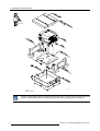
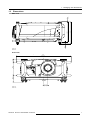
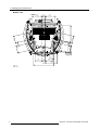
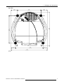

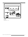
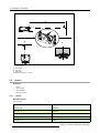
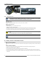
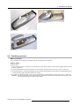
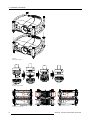
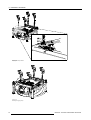
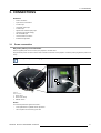
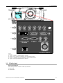
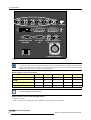
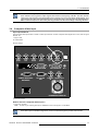
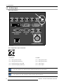
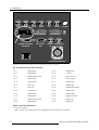
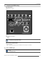
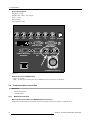
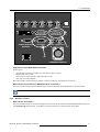
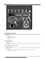
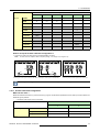
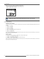
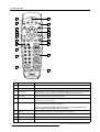
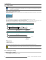
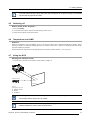
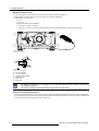
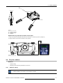
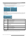
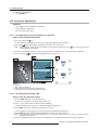
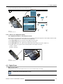
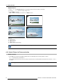
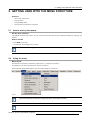


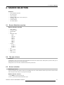
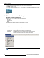
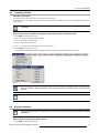
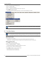
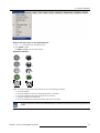

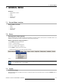
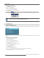
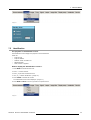
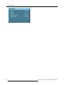
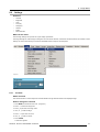
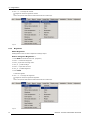
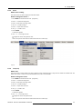
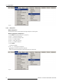
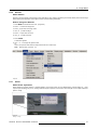
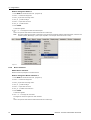
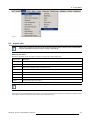
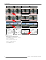
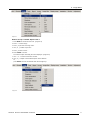
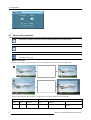
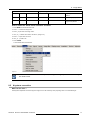
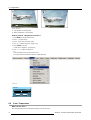
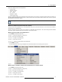
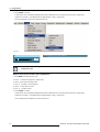
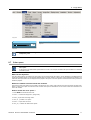
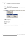
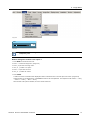
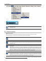
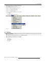
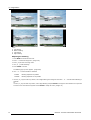
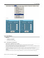
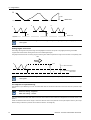
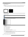
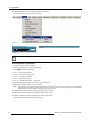
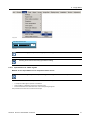
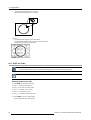
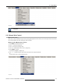

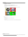
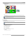
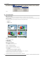
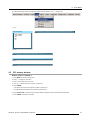
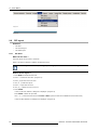
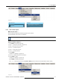
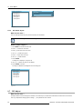
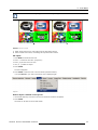

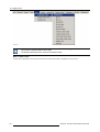
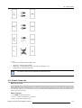
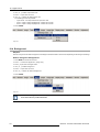
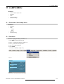
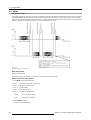
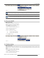
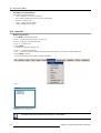
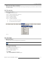
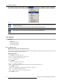
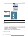
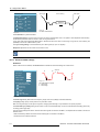
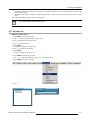
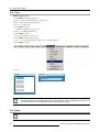
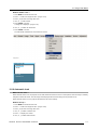
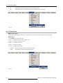
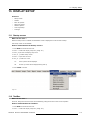
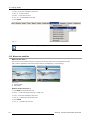
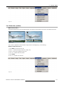
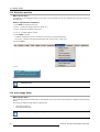
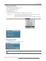
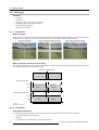
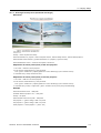
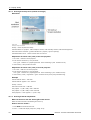

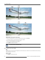
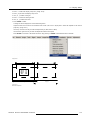

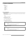
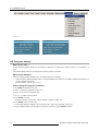
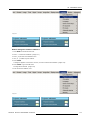
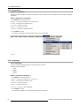
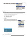
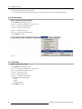
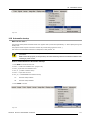
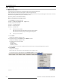
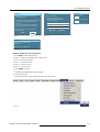

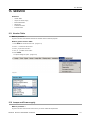
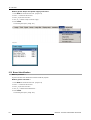
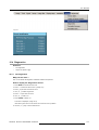
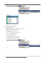
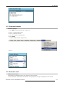
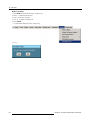
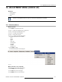
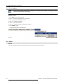
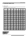
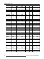
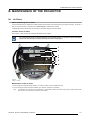
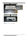
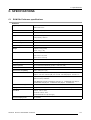
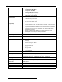
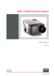
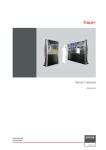
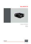
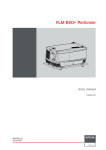
![FLM HD18 [v08]](http://vs1.manualzilla.com/store/data/005664321_1-9e0d84f2b9cac33a4ebfb5904f0dafa1-150x150.png)