1
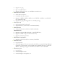
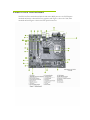
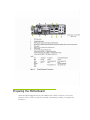
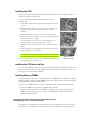
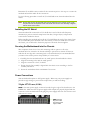
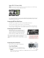
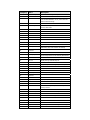
Before You Begin… Parts NOT in the Kit This kit contains all the hardware necessary to install and connect your new EVGA nForce motherboard. However, it does not contain the following items that must be purchased separately to make the motherboard functional. Intel microprocessor: Intel Core 2 Extreme, Intel Core 2 Quad, Intel Core 2 Duo, Pentium EE, Pentium, and Celeron Socket 775 CPU’s. (up to 1066Mhz FSB on 610i motherboards) Cooling fan and heat sink for the microprocessor System memory support: Supports single channel DDR2 533/667/800, (800MHz not supported on 610i Motherboards ) Power Supply The power supply requirement is dependent upon the components used in the system. We recommend at least a 350 watt power supply for a basic configuration. *Graphics Card* This motherboard comes with an onboard graphics adapter; it also has a PCI express x16 slot for graphics cards. These instructions help you install each of the parts listed so you can have a functioning motherboard. As you go through the installation instructions, we are assuming you have purchased the necessary parts. Motherboard Specifications Size mATX form factor. Microprocessor support Intel Core 2 Extreme, Intel Core 2 Quad, Intel Core 2 Duo, Pentium EE, Pentium, and Celeron. (610i supports up to 1066MHz FSB CPU’s) Operating systems Supports Windows XP and Windows Vista. Contains NVIDIA nForce MCP and integrated GeForce graphics System Memory • Single-channel DDR2 800/667/533 (800MHz RAM not supported on 610i) • Supports up to 4 GB DDR2 memory (2GB x 2) USB 2.0 Ports • Supports hot plug • Up to ten USB 2.0 ports • Supports USB 2.0 protocol up to 480Mbps transmission rate Onboard Serial ATA II • • • 3Gb/s data transfer rate Four Serial ATA II connectors Support for RAID 0, RAID 1, RAID 0+1, and RAID 5, (RAID 0+1 and RAID 5 not supported on 610i) • Supports hot plug and NCQ (Native Command Queuing ) Onboard LAN • LAN interfaces built-in onboard • Gigabit Ethernet (10/100 LAN on 610i motherboards) Onboard 1394 • 1394 port and header available on 630i Motherboards Onboard Audio • Supports 8-channel audio (6-channel on 112-CK-NF71-T1) • Supports S/PDIF output (on 630i motherboards) • Supports Jack-Sensing function PCI Express x16 Support • Supports 4 GB/sec (8 GB/sec concurrent) bandwidth Onboard Video • • Integrated video All models support VGA out. On models with DVI, out a single link digital display is supported. Certain models come equipped with an HDMI connecter to connect an HDTV. Dual display is supported with VGA and DVI or VGA and HDMI. Expansion Slots • • • Two PCI slots One PCI Express x1 slot One PCI Express x16 Graphics slot Hardware Installation This section will guide you through the installation of the motherboard. The topics covered in this section are: Preparing the motherboard • Installing the CPU • Installing the CPU fan • Installing the memory Installing the motherboard Connecting cables and setting switches Safety Instructions To reduce the risk of fire, electric shock, and injury, always follows basic safety precautions. Remember to remove power from your computer by disconnecting the AC main source before removing or installing any equipment from/to the computer chassis. EVGA nForce Motherboard The EVGA nForce motherboard with the 600 series MCP processor is a PCI Express motherboard with an onboard GeForce graphics card. Figure 1 shows the 7150/630i motherboard and Figures 2 shows the back panel connectors. Preparing the Motherboard The motherboard shipped in the box does not contain a CPU or memory. You need to purchase a CPU, a CPU heat sink/fan assembly, and memory module(s) to complete this installation. Installing the CPU Be very careful when handling the CPU. Hold the processor only by the edges and do not touch the bottom of the processor. Use the following procedure to install the CPU onto the motherboard. 1. Unhook the socket lever by pushing down and away from the socket. 2. Lift the load plate. There is a protective socket cover on the load plate to protect the socket when there is no CPU installed. 3. Remove the protective socket cover from the load plate. 4. Remove the processor from its protective cover, making sure you hold it only by the edges. It is a good idea to save the cover so that whenever you remove the CPU, you have a safe place to store it. 5. Align the notches in the processor with the notches on the socket. 6. Lower the processor straight down into the socket with out tilting or sliding it into the socket Note: Make sure the CPU is fully seated and level in the socket. 7. Close the load plate over the CPU and press down while you close and engage the socket lever. Align notches with notches on the CPU Installing the CPU heat sink/fan There are many different heat sink types that can be used with this motherboard. Follow the instruction that came with your fan assembly. Be sure that the fan orientation is correct for your chassis type and your fan assembly. Installing Memory DIMMs Your new motherboard has two 1.8V 240-pin slots for DDR2 memory. These slots support 256 MB, 512 MB, 1 GB, and 2 GB DDR2 technologies. There must be at least one memory bank populated to ensure normal operation. *Any of the two DIMM slots may be used as primary if only using one memory module. 1. Unlock a DIMM slot by pressing the module clips outward. 2. Align the memory module to the DIMM slot, and insert the module vertically into the DIMM slot. The plastic clips at both sides of the DIMM slot automatically lock the DIMM into the connector. Installing the Motherboard The sequence of installing the motherboard into the chassis depends on the chassis you are using and if you are replacing an existing motherboard or working with an empty chassis. Determine if it would be easier to make all the connections prior to this step or to secure the motherboard and then make all the connections. Use the following procedure to install the I/O shield and secure the motherboard into the chassis. Note: Be sure that the CPU fan assembly has enough clearance for the chassis covers to lock into place and for the expansion cards. Also make sure the CPU Fan assembly is aligned with the vents on the covers. Installing the I/O Shield The motherboard kit comes with an I/O shield that is used to block radio frequency transmissions, protects internal components from dust, foreign objects, and promotes correct airflow within the chassis. Before installing the motherboard, install the I/O shield from the inside of the chassis. Press the I/O shield into place and make sure it fits securely. If the I/O shield does not fit into the chassis, you would need to obtain the proper size from the chassis supplier. Securing the Motherboard into the Chassis Most computer chassis have a base with mounting studs or spacers to allow the motherboard to be secured to the chassis and help to prevent short circuits. If there are studs that do not align with a mounting hole on the motherboard, it is recommended that you remove that stud to prevent the possibility of a short circuit. 1. 2. 3. 4. Carefully place the motherboard onto the studs/spacers located inside the chassis. Align the mounting holes with the studs/spacers. Align the connectors to the I/O shield. Ensure that the fan assembly is aligned with the chassis vents according to the fan assembly instruction. 5. Secure the motherboard with a minimum of six screws. Power Connections This motherboard requires an ATX power supply. Make sure your power supply can provide enough wattage to power all the components you will be installing. 24-pin ATX Power (PWR1) is the main power supply connector located along the edge of the board next to the DIMM slots. Make sure that the power supply cable and pins are properly aligned with the connector on the motherboard. Firmly plug the power supply cable into the connector and make sure it is secure. PWR1 PWR1 connector Plug power cable from system power supply to PWR1 8-pin ATX 12V Power (PWR2) PWR2, the 8-pin ATX 12V power connection, is used to provide power to the CPU. Align the pins to the connector and press firmly until seated. It is strongly recommended that you use an 8-pin ATX 12V power supply; however a four-pin power supply may be used. The 8 pin power connection is keyed for either a 4 pin or 8 pin connector to only go in one way. Connecting IDE Hard Disk Drives The IDE connector supports Ultra ATA 133/100/66 IDE hard disk drives. Connect the cable end with a single connector to the motherboard. If you install two hard disk drives, you must configure the second drive as a slave device by setting its jumper accordingly. Refer to the hard disk documentation for the jumper settings. Connecting Serial ATA Cables The Serial ATA II connector is used to connect the Serial ATA II device to the motherboard. These connectors support the thin Serial ATA II cables for primary storage devices. The current Serial ATA II interface allows up to 300MB/s data transfer rate. There are four serial ATA connectors on the motherboard that support RAID 0, RAID 1, RAID 5, and RAID 0+1 configurations. (610i motherboards support RAID0 or RAID1 only) Connecting Internal Headers Please refer to item 10 in figure 1 Motherboard. Front Panel Header The front panel header on this motherboard is one connector used to connect the following four cables: PWRLED Attach the front panel power LED cable to the PWR LED connector. The Power LED indicates the system’s status. PWRSW Attach the power button cable from the case to these two pins. Pressing the powerbutton on the front panel turns the system on off rather than using the power supply button. HD_LED RESET Attach the hard disk drive indicator LED cable to these two pins. The HDD indicator LED indicates the activity status of the hard disks. Attach the Reset switch cable from the front panel of the case to these two pins. The system restarts when the RESET switch is pressed. USB Headers The motherboard contains 10-pin internal USB header connector(s). These can be used for your front panel USB connections or a USB bracket. Audio The audio connector supports the HD audio standard. Most cases come with a 10 pin standard block which will align and plug directly in to the header. In some cases there will be individual plugs which will need to be plugged in. Table 1. Front Audio Connector Connector Pin Front Audio Connector 1 PORT1_L - Analog Port 1 - left channel (Microphone) 2 AUD_GND - Ground 3 PORT1_R – Analog Port 1 – right channel (Microphone) 1 3 5 7 9 2 4 6 8 10 Signal 4 PRESENCE# - Active signal that indicates FP audio is present 5 PORT2_R – Analog Port 2 - right channel (Headphone) 6 SENSE1_RETURN – Jack detection return for front panel (Jack1) 7 SENSE_SEND – Jack detection sense line 8 Empty 9 PORT2_L – Analog port 2 – left channel (Headphone) 10 SENSE2_RETURN – Jack detection return for front panel (Jack2) Fan Connections There are two types fan connections, the system fan and the CPU fan. The fan speed can be detected and viewed in the PC Health Status section of the CMOS Setup. Both fans are automatically turned off after the system enters S3, S4 and S5 mode. Note that the CPU fan cable can be either a 3-pin or a 4-pin connector. Connect a 3-pin connector to pins 1, 2, and 3 on the motherboard connector. CPU Fan Connector 4 3 2 1 GND SENSE PWR CONTROL FDD Connector The motherboard supports a standard 360K, 720K, 1.2M, 1.44m, and a 2.88M floppy disk drive (FDD). Speaker The speaker connector is used to connect the chassis speakers to the motherboard. Please refer to item 9 in figure 1 Motherboard. Expansion Slots The EVGA nForce motherboard contains four expansion slots, two PCI Express slots and two PCI slots. For a full list of PCI Express x16 graphics card supported by this motherboard, go to www.evga.com/products/. PCI Slots The two PCI slots support many expansion cards such as a LAN card, USB card, SCSI card and other cards that comply with PCI specifications. When installing a card into the PCI slot, be sure that it is fully seated. Secure the card’s metal bracket to the chassis back panel with the screw used to hold the blank cover. PCI Express x1 Slot There is one PCI Express x1 slot that is designed to accommodate less bandwidth-intensive cards, such as a modem or LAN card. The x1 slot provides 250 MB/sec bandwidth. PCI Express x16 Slot The PCI Express x16 slot is reserved for a graphics card. The bandwidth of the x16 slot is up to 4GB/sec (8GB/sec concurrent). When installing a PCI Express x16 card, be sure the retention clip snaps and locks the card into place. If the card is not seated properly, it could cause a short across the pins. Secure the card’s metal bracket to the chassis back panel with the screw used to hold the blank cover. Install your Operating System Boot up your machine, setup any hardware configurations in the BIOS setup if needed. Boot from your OS disk. Once your operating system is installed use the driver disk to install the appropriate drivers. On-board LED Codes On-board LED Codes Code(hex) Name 01 Reserved Description 02 Jumps to E000 segment Execution of POST routines in E000 03 Early Superio Init Early Initialized the super IO 04 Reserved 05 Blank video 06 Reserved 07 Init KBC Keyboard controller init 08 KB test Test the Keyboard 09 Reserved 0A Mouse 0B Reserved 0C Reserved 0D Reserved 0E CheckSum 0F Reserved 10 Autodetect 11 Reserved 12 Test CMOS 13 Reserved 14 Load Chipset 15 Reserved 16 Init Clock 17 Reserved 18 InitCPU Reset Video controller Init Initialized the mouse Check Check the integrity of the ROM,BIOS and message EEPROM Check Flash type and copy flash Write/erase routines Test and Reset CMOS Load Chipset Defaults Initialize onboard clock generator CPU ID and initialize L1/L2 cache 19 Reserved 1A Reserved 1B Setup Interrupt Initialize first 120 interrupt vectors Vector Table with SPURIOUS_INT_HDLR and initialize INT 00h-1Fh according to INT_TBL 1C CMOS Battery Check Test CMOS and check Battery Fail 1D Early PM Early PM initialization Code(hex) Name 1E Reserved 1F Re-initial KB 20 Reserved 21 HPM init Description Load keyboard matrix Init Heuristic Power Management (HPM) 22 Reserved 23 Program chipset Early Programming of chipset registers 24 Init PNP Init PNP 25 Shadow VBIOS Shadow system/video BIOS 26 Clock Gen Init onboard clock generator and sensor 27 Setup BDA Setup BIOS DATA AREA (BDA) 28 Reserved 29 CPU Speed detect 2A Reserved 2B Init video 2C Reserved 2D Video memory test 2E Reserved 2F Reserved 30 Reserved 31 Reserved 32 Reserved 33 Early keyboard reset 34 Reserved 35 Test DMA Controller 0 36 Reserved 37 Test DMA Controller 1 38 Reserved 39 Test DMA Page Registers 3A Reserved 3B Reserved 3C Test Timer 3D Reserved 3E Test 8259-1 Mask 3F Reserved 40 Test 8259-2 Mask 41 Reserved 42 Reserved 43 Test Stuck Interrupt 44 Reserved Chipset programming and CPU Speed detect Initialize Video Test Video Memory and display Logos Early Keyboard Reset Test DMA channel 0 Test DMA channel 1 Test DMA Page Registers Test 8254 Timer 0 Counter 2. Verify 8259 Channel 1 masked interrupts by alternately turning off and on the interrupt lines. Verify 8259 Channel 2 masked interrupts by alternately turning off and on the interrupt lines. Turn off interrupts then verify no 8259's Interrupt mask register is on. Test 8259 Force an interrupt and verify the interrupt occurred. Code(hex) Name Description 45 Reinit serial port Reinitialize Preboot agent serial port 46 Reserved 47 EISA Test 48 Reserved 49 Size Memory 4A Reserved 4B Reserved 4C Reserved 4D Reserved 4E Init APIC 4F Reserved 50 USB init Initialize 51 Reserved 52 Memory Test 53 Reserved 54 Reserved 55 CPU display 56 Reserved 57 PnP Init 58 Reserved 59 Setup Virus 5A Reserved 5B Awdflash Load 5C Reserved 5D Onboard I/O Init 5E Reserved 5F Reserved 60 Setup enable 61 Reserved 62 Reserved 63 Initialize Mouse 64 Reserved 65 PS2 Mouse special 66 Reserved 67 ACPI init 68 Reserved 69 Init Cache 6A Reserved 6B Setup 6C Reserved If EISA non-volatile memory checksum is good, execute EISA initialization. If not, execute ISA tests and clear EISA mode flag. Size base memory from 256K to 640K and extended memory above 1MB. Initialize APIC and set MTRR USB controller Test all memory of memory above 1MB using Virtual 8086 mode, page mode and clear the memory Detect CPU speed and display CPU vendor specific version string and turn on all necessary CPU features Display PnP logo and PnP early init Setup virus protect according to protect setup If required, will auto load Awdflash. exe in POST Initializing onboard superIO Display setup message and enable setup functions Detect if mouse is present, initialize mouse, install interrupt vectors. Special treatment to PS2 Mouse port ACPI sub-system initializing Initialize cache controller Enter setup check and auto configuration check up Code(hex) Name Description 6D Initialize Floppy Initialize floppy disk drive 6E Reserved 6F FDD install 70 Reserved 71 Reserved 72 Reserved 73 Initialize Hard Drive 74 Reserved 75 Detect HDD 76 Reserved 77 Detect serial ports 78 Reserved Install FDD and setup BIOS data area parameters Initialize hard drive controller IDE device detection Initialize serial ports 79 Reserved 7A Detect parallel ports 7B Reserved 7C HDD Write Protect 7D Reserved 7E Reserved 7F POST error check 80 Reserved 81 Reserved 82 Security Check Ask password security. 83 Write CMOS Write all CMOS values back to RAM and clear screen 84 Display PNP Display PNP devices 85 USB Final Init Final USB initialization 86 Reserved 87 Reserved 88 Reserved 89 Setup ACPI tables 8A Reserved 8B Option ROM Detect 8C Reserved 8D Enable Parity 8E Reserved 8F IRQ12 Enable 90 Reserved 91 Reserved 92 Reserved 93 Boot Medium Read Detect and store boot partition head and cylinders values in RAM 94 Final Init Final init for last micro details before boot 95 NumLock Set NumLock status according to Setup 96 Boot Attempt Set low stack Boot via INT 19h. C0 Base CPU test Read/Write CPU registers Initialize parallel ports HDD check for write protection Check POST error and display them and ask for user intervention Setup ACPI tables Scan for Option ROMs Check Enable Parity Check Enable IRQ12 if mouse present Code(hex) Name Description C1 Memory Presence Base memory detect C2 Early Memory Board Initialization C3 Extend Memory Turn on extended memory, cache initialization C4 Special Display First display initialization C5 Early Shadow Early shadow enable for fast boot C6 Cache presence External caches FF Boot