1
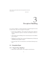
µMPS2
Principles of Operation
The Virtual Square Lab
Michael Goldweber
Renzo Davoli
Xavier University
University of Bologna
Kaya, µMPS & µMPS2 are products of the Virtual Square Lab.
See virtualsquare.org/ and wiki.virtualsquare.org/.
The µMPS & µMPS2 home page is www.cs.xu.edu/uMPS/
c
Copyright !2009,
2011 Michael Goldweber, Renzo Davoli and, and the Virtual
Square Lab. Permission is granted to copy, distribute and/or modify this document under the terms of the GNU Free Documentation License, Version 1.2 or
any later version published by the Free Software Foundation; with the exception
of the Front-Cover text, the Title Page with the Logo (recto of this page), and the
Back-Cover text. As per the Virtual Square Logo: all rights reserved.
Contents
Preface
viii
I The Architecture of µMPS2
1
1
Introduction
1
2
System Structure and Overview
3
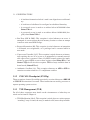
3
Exception Handling
3.1 Exception Types . . . . . . . . .
3.2 Processor Actions on Exception
3.3 The Cause CP0 Register . . . .
3.4 The Truth about ROM . . . . .
4
5
.
.
.
.
.
.
.
.
.
.
.
.
.
.
.
.
.
.
.
.
.
.
.
.
Memory Management
4.1 Physical Memory . . . . . . . . . . . . . .
4.2 Virtual Memory in µMPS2 . . . . . . . . .
4.3 Virtual Address Translation in µMPS2 . . .
4.4 CP0 Registers used in Address Translation .
4.5 The Truth About ROM . . . . . . . . . . .
.
.
.
.
.
.
.
.
.
.
.
.
.
.
.
.
.
.
.
.
.
.
.
.
.
.
.
.
.
.
.
.
.
.
.
.
.
.
.
.
.
.
.
.
.
.
.
.
.
.
.
.
.
.
.
.
.
.
.
.
.
.
.
.
.
.
.
.
.
.
.
.
.
.
.
.
.
.
.
.
.
.
.
.
.
.
.
.
.
.
Device Interfaces
5.1 Device Registers . . . . . . . . . . . . . . . . . . . . . . . .
5.2 The Bus Device, Processor Local Timers, and Device Bit Maps
5.3 Disk Devices . . . . . . . . . . . . . . . . . . . . . . . . . .
5.4 Tape Devices . . . . . . . . . . . . . . . . . . . . . . . . . .
5.5 Network (Ethernet) Adapters . . . . . . . . . . . . . . . . . .
5.6 Printer Devices . . . . . . . . . . . . . . . . . . . . . . . . .
iii
.
.
.
.
.
.
.
.
.
.
.
.
.
.
.
.
.
.
.
8
8
10
15
16
.
.
.
.
.
17
17
19
20
26
27
.
.
.
.
.
.
29
31
32
37
39
41
44
CONTENTS
iv
5.7
Terminal Devices . . . . . . . . . . . . . . . . . . . . . . . . . .
45
6 Summary of ROM & Library Services
49
6.1 Bootstrap ROM Functionality . . . . . . . . . . . . . . . . . . . 50
6.2 New ROM Services/Instructions . . . . . . . . . . . . . . . . . . 50
6.3 Accessing Registers & Assembler Instructions in C . . . . . . . . 52
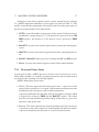
7 µMPS2 Multiprocessor Support
7.1 Machine Control Registers . . . . . . . . . . . . . . .
7.2 Interrupt Delivery Control . . . . . . . . . . . . . . .
7.3 Device Register Memory Map - The Complete Picture
7.4 Inter-Processor Interrupts (IPI’s) . . . . . . . . . . . .
7.5 Special ROM Services/Instructions . . . . . . . . . . .
.
.
.
.
.
.
.
.
.
.
.
.
.
.
.
56
. . . 56
. . . 59
. . . 62
. . . 64
. . . 65
II Interacting with µMPS2
68
8 Programming and Compiling for µMPS2
8.1 A Word About Endian-ness . . . . . . . . . . . . . .
8.2 C Language Software Development . . . . . . . . .
8.3 The Compiling Process . . . . . . . . . . . . . . . .
8.4 Putting It All Together: The Development Toolchain
8.5 Encapsulation Strategy for C Programming . . . . .
69
70
71
73
80
82
9 The µMPS2 GUI
9.1 The µMPS2 Simulator . . . . . . . . . . . . . . .
9.2 UMPS 2 Invocation and Machine Configurations . .
9.3 Using UMPS 2 . . . . . . . . . . . . . . . . . . . .
9.4 Using The UMPS 2- MKDEV Device Creation Utility
.
.
.
.
.
.
.
.
.
.
.
.
.
.
.
.
.
.
.
.
.
.
.
.
.
.
.
.
.
.
.
.
.
.
.
.
.
.
.
.
.
.
.
.
.
.
.
.
.
.
.
.
.
.
.
85
. . . 85
. . . 86
. . . 87
. . . 90
10 Debugging in µMPS2
92
10.1 µMPS2 Debugging Strategies . . . . . . . . . . . . . . . . . . . . 93
10.2 Common Pitfalls to Watch Out For . . . . . . . . . . . . . . . . . 95
List of Figures
2.1
Status Register . . . . . . . . . . . . . . . . . . . . . . . . . . .
3.1
3.2
3.3
3.4
VM and KU/IE Stack Push
Old and New State Areas .
ROM Reserved Frame . .
Cause CP0 Register . . .
.
.
.
.
.
.
.
.
.
.
.
.
.
.
.
.
.
.
.
.
.
.
.
.
.
.
.
.
.
.
.
.
.
.
.
.
.
.
.
.
.
.
.
.
.
.
.
.
.
.
.
.
.
.
.
.
.
.
.
.
.
.
.
.
.
.
.
.
.
.
.
.
.
.
.
.
11
13
14
15
4.1
4.2
4.3
4.4
4.5
4.6
4.7
4.8
4.9
4.10
4.11
4.12
Physical Address Format . . . .
The Physical Address Space . .
ROM Areas and Device Regisers
Virtual Address Format . . . . .
The Virtual Address Space . . .
ROM Reserved Frame . . . . .
Segment Table Format . . . . .
Page Table (PgTbl) Format . . .
EntryHi CP0 Control Register .
EntryLo CP0 Control Register .
Random CP0 Control Register .
Index CP0 Control Register . .
.
.
.
.
.
.
.
.
.
.
.
.
.
.
.
.
.
.
.
.
.
.
.
.
.
.
.
.
.
.
.
.
.
.
.
.
.
.
.
.
.
.
.
.
.
.
.
.
.
.
.
.
.
.
.
.
.
.
.
.
.
.
.
.
.
.
.
.
.
.
.
.
.
.
.
.
.
.
.
.
.
.
.
.
.
.
.
.
.
.
.
.
.
.
.
.
.
.
.
.
.
.
.
.
.
.
.
.
.
.
.
.
.
.
.
.
.
.
.
.
.
.
.
.
.
.
.
.
.
.
.
.
.
.
.
.
.
.
.
.
.
.
.
.
.
.
.
.
.
.
.
.
.
.
.
.
.
.
.
.
.
.
.
.
.
.
.
.
.
.
.
.
.
.
.
.
.
.
.
.
.
.
.
.
.
.
.
.
.
.
.
.
.
.
.
.
.
.
.
.
.
.
.
.
.
.
.
.
.
.
.
.
.
.
.
.
17
18
19
20
21
22
23
23
23
24
26
26
5.1
5.2
5.3
5.4
5.5
5.6
5.7
5.8
5.9
Device Registers Area . . . . . . . . . . . . . . . . . . . . . . .
Installed Devices Bit Map . . . . . . . . . . . . . . . . . . . . . .
Disk Device DATA1 Field . . . . . . . . . . . . . . . . . . . . .
Disk Device COMMAND Field . . . . . . . . . . . . . . . . . .
Network Adapter DATA0 Field . . . . . . . . . . . . . . . . . . .
Network Adapter DATA1 Field . . . . . . . . . . . . . . . . . . .
Printer Device DATA0 Field . . . . . . . . . . . . . . . . . . . .
Terminal Device TRANSM STATUS and RECV STATUS Fields
Terminal TRANSM COMMAND and RECV COMMAND Fields
.
.
.
.
.
.
.
.
v
5
33
36
37
39
43
43
44
46
47
LIST OF FIGURES
vi
6.1
VM and KU/IE Stack Pop . . . . . . . . . . . . . . . . . . . . .
52
7.1
7.2
7.3
7.4
7.5
7.6
7.7
7.8
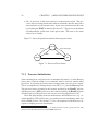
Processor Power States . . . . . . . . . . . . . . . . . . . . . .
Interrupt Delivery Control Subsystem Functional Block Diagram
IRT Entry Format . . . . . . . . . . . . . . . . . . . . . . . . .
Interrupt Routing Table Register Address Map . . . . . . . . . .
The TPR register . . . . . . . . . . . . . . . . . . . . . . . . .
Device Register Memory Map . . . . . . . . . . . . . . . . . .
Outbox Register . . . . . . . . . . . . . . . . . . . . . . . . . .
Inbox Register . . . . . . . . . . . . . . . . . . . . . . . . . . .
.
.
.
.
.
.
.
.
58
59
60
61
62
63
64
65
8.1
.aout File Format . . . . . . . . . . . . . . . . . . . . . . . . . .
76
List of Tables
3.1
Cause Register Status Codes . . . . . . . . . . . . . . . . . . . . 16
5.1
5.2
5.3
5.4
5.5
5.6
5.7
5.8
5.9
5.10
5.11
5.12
5.13
5.14
5.15
5.16
5.17
Interrupt Line and Device Class Mapping
Device Register Layout . . . . . . . . . .
Bus Register Area . . . . . . . . . . . . .
Installed Devices Bit Map Addresses . . .
Interrupting Devices Mit Map Addresses .
Disk Drive Status Codes . . . . . . . . .
Disk Drive Command Codes . . . . . . .
Tape Marker Codes . . . . . . . . . . . .
Tape Drive Status Codes . . . . . . . . .
Tape Drive Command Codes . . . . . . .
Tape Drive Status Codes . . . . . . . . .
Network Adapter Command Codes . . . .
Printer Device Status Codes . . . . . . .
Printer Device Command Codes . . . . .
Terminal Device Register Layout . . . . .
Terminal Device Status Codes . . . . . .
Terminal Device Command Codes . . . .
.
.
.
.
.
.
.
.
.
.
.
.
.
.
.
.
.
.
.
.
.
.
.
.
.
.
.
.
.
.
.
.
.
.
.
.
.
.
.
.
.
.
.
.
.
.
.
.
.
.
.
.
.
.
.
.
.
.
.
.
.
.
.
.
.
.
.
.
.
.
.
.
.
.
.
.
.
.
.
.
.
.
.
.
.
.
.
.
.
.
.
.
.
.
.
.
.
.
.
.
.
.
.
.
.
.
.
.
.
.
.
.
.
.
.
.
.
.
.
.
.
.
.
.
.
.
.
.
.
.
.
.
.
.
.
.
.
.
.
.
.
.
.
.
.
.
.
.
.
.
.
.
.
.
.
.
.
.
.
.
.
.
.
.
.
.
.
.
.
.
.
.
.
.
.
.
.
.
.
.
.
.
.
.
.
.
.
.
.
.
.
.
.
.
.
.
.
.
.
.
.
.
.
.
30
32
34
35
36
38
38
40
40
41
42
43
45
45
46
46
47
6.1
6.2
6.3
6.4
TLB Commands . . . . . . . . . . . . . . . .
Control Register Read Commands . . . . . .
Control Register Write Commands . . . . . .
The LDST & Other Special ROM Instructions
.
.
.
.
.
.
.
.
.
.
.
.
.
.
.
.
.
.
.
.
.
.
.
.
.
.
.
.
.
.
.
.
.
.
.
.
.
.
.
.
.
.
.
.
53
54
54
55
7.1
7.2
Machine Control Register Address Map . . . . . . . . . . . . . . 56
Interrupt Delivery Controller Processor Interface Register Map . . 62
8.1
.aout File Format Detail . . . . . . . . . . . . . . . . . . . . . . . 75
vii
.
.
.
.
.
.
.
.
.
.
.
.
.
.
.
.
.
Preface
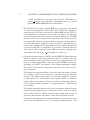
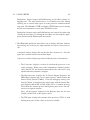
In my junior year as an undergraduate I took a course titled, “Systems Programming.” The goal of this course was for each student to write a small, simple multitasking operating system, in S/360 assembler, for an IBM S/360. The students
were given use of a machine emulator, Assist-V, for the development process.
Assist, was a S/360 assembler programming environment. (Think SPIM for the
70’s.) Assist-V was an extension of Assist that supported privileged instructions in
addition to various emulated “attached” devices. The highlight of the course was
if your operating system ran correctly (or at least without discernible errors), you
would be granted the opportunity, in the dead of night, to boot the University’s
mainframe, an IBM S/370, with your operating system. (Caveat: The University used VM, IBM’s virtual machine technology. Hence students didn’t actually
boot the whole machine with their OS’s, but just one VM partition. Nevertheless, booting/running a VM partition and booting/running the whole machine are
isomorphic tasks.) No question, booting and running a handful of tasks concurrently on the University’s mainframe with my own OS was one of highlights of
my undergraduate education!
For my senior project I undertook to update Assist-V to the S/370 ISA. Since
neither Assist nor Assist-V supported floating point instructions, this basically
meant adding virtual memory support to Assist-V. I recall my surprise in the mid1980’s receiving an email from some institution that was still using Assist-V/370
to support their operating systems course.
My experience of writing a complete operating system repeated itself in graduate school. In this case the machine emulator was the Cornell Hypothetical Instruction Processor (CHIP); a made up architecture that was a cross between a
PDP-11 and an IBM S/370. The operating system design was a three phase/layer
affair called HOCA by its creator. While there was no real machine to test with,
the thrill and sense of accomplishment of successfully completing the task, to say
nothing of the many lessons learned throughout the experience were no less than
the earlier experience.
viii
PREFACE
ix
Time passed and like Assist-V/370, CHIP fell out of use. (It only ran on Dec
Vaxen or Sun 3’s. It also defied at least two serious attempts at being ported to
more current platforms.) A professor myself, now teaching operating systems, I
experimented with the courseware systems of the day. Sadly these tools, while
of very high quality, all fell short of the pedagogic experience of having students
write a complete operating system supporting virtual memory, a host of devices
types, and being able to run a set of tasks concurrently.
In the late 1990’s Professor Renzo Davoli and one of his graduate students
Mauro Morsiani, in the spirit of both Assist-V/370 and CHIP, created MPS, a
MIPS 3000 machine emulator that not only authentically emulated the processor
(still no floating point), but also faithfully emulated five different device categories. Furthermore, they updated the HOCA project for this new architecture.
Once again, students could take their operating system, developed and debugged
on MPS (which also contained an excellent debugging facility) and run it unchanged on a real machine.
Unfortunately, modern architectures like the MIPS 3000 which are designed
to achieve super high speed operation can be overly complex in their detail, obscuring the basic underlying features and unnecessarily complicating students’
understanding. Hence we (Professor Davoli and myself) learned via class testing that MPS due to the complexity of MIPS’ virtual memory management was
unsuitable for undergraduates. In the MIPS architecture, virtual memory is always on, all address translation is performed through a small fixed size TLB, and
hence even the OS maintained page tables for itself and user processes are kept
in virtual memory. Furthermore, the physical address space for the kernel and
its data structures are permanently disjoint from its virtual address space. While
these RISC-design features allow for an extremely fast processor they complicate
introductory students’ understanding; in particular with the circularity of an OS
always running with VM on and whose page tables are kept in virtual memory.
We set out to create µMPS – a pedagogically appropriate machine emulator
appropriate for use by undergraduates. The primary design goal of µMPS was to
implement a virtual memory management subsystem that more closely matched
the conceptual description found in popular introductory OS texts. More specifically:
• A VM bit was introduced into the STATUS control register allowing for
address translation to be turned on and off.
• Formal segment table and page table formats were introduced.
PREFACE
x
• If the TLB does not contain the appropriate entry, µMPS, via the appropriate
segment and page tables locates the missing entry and inserts it into the
TLB.
• All of the segment and page tables, both for the kernel and for user processes
are stored in permanent physical locations. This eliminates the circularity
of having the OS data structures for supporting virtual memory being kept
in (and hence managed by the) virtual memory.
• The cross compiler that accompanies µMPS compiles the student OS to
reside in a different segment than the one the user programs are compiled
to reside in.
• The number of segments was reduced to three with one of these segments
(ksegOS) reserved for kernel use only. Furthermore, a formal segment table
was introduced.
• The size of the TLB was made user configurable.
• Two new TLB-Mgmt. exceptions were introduced:
– Bad-PTE: For when a incorrectly formed page table is discovered.
– PTE-MISS: For when a (well-formed) page table is searched unsuccessfully for a given entry.
Outside of the simplification of the virtual memory management subsystem,
µMPS is virtually identical to the MPS emulator upon which it is based. This
includes:
• Support for up to eight memory-mapped DMA disk and tape devices.
• Support for up to eight memory-mapped printers and read/write capable
terminal devices.
• Support for up to eight memory-mapped ethernet network devices.
• A sophisticated development, user interface, testing, and debugging environment.
PREFACE
xi
As a raw machine emulator, µMPS can support a wide variety of undergraduate, and graduate-level projects. One in particular is the “Kaya Operating System
Guide,” also available from the Virtual Square Lab. This project, a direct descendant of the HOCA project is designed for three levels/phases to be completed by
senior-level undergraduate students.
Renzo and I wish to offer our heartfelt thanks to Mauro Morsiani and Tomislav Jonjic for their development efforts. Mauro generously donated his time to
modify MPS into µMPS. µMPS and the accompanying Kaya Project Guide were
originally released in 2004. Kaya, in 2009, was updated and both the Kaya Project
Guide and this manual were first published in their current form in 2009. More recently, in 2011, µMPS was updated by Tomislav Jonjic to µMPS2 with a new GUI
and multiprocessor support. µMPS2 is 100% backward compatible with µMPS.
Furthermore Tomislav also wrote Chapter 7 of this guide.
While µMPS is still available, it is no longer being supported. As there are two
versions of the µMPS emulator, there are two versions of the Principles of Operation
manual, the outdated µMPS Principles of Operation, and this new µMPS2 version.
As an undergraduate, while working on the Assist-V project, my most valuable
resource, besides the yellow S/370 assembler programming card, was the orange
covered IBM “S/370 Principles of Operations” manual, we affectionately called
pops. This book, while unlikely to enjoy the storied history of the orange IBM
pops manual, is nevertheless the definitive guide to the operation of the µMPS2
emulator.
Finally in addition to offering our thanks to Mauro Morsiani and Tomislav
Jonjic, Renzo and I also wish to Justin Zimmerman who wrote the first draft of
Section 5.5. Finally we wish to thank our wives, Alessandra and Mindy and our
children, without whose inexhaustible patience projects such as this would never
see the light of day.
Michael Goldweber
August, 2009
Updated: August, 2011
Part I
The Architecture of µMPS2
Computer system architecture is the attributes of a computing system as
seen by the programmer, i.e. the conceptual structure and functional behavior, as distinct from the organization of the data flows and controls,
the logic design, and the physical implementation.
Brooks & Amdahl, Blaauw & Brooks - on the Architecture of the IBM
System/360
1
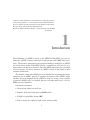
Introduction
The architecture of µMPS2 is based on the MIPS R2/3000 RISC processor architecture. µMPS2’s integer instruction set mirrors that of the MIPS almost perfectly. The memory management and exception handling capabilities of µMPS2
are loosely based on that of the MIPS. Finally, a complete set of I/O devices (e.g.
disks, printers, terminals) is provided. Since the MIPS architecture does not detail
a device interface, the device interface of µMPS2 is based on that found in other
common architectures.
This manual, along with a MIPS processor handbook to document the integer
instruction set of µMPS2, presents a complete description of the µMPS2 virtual
machine. Since development for the µMPS2 is done in C using a cross compiler
to generate µMPS2 code, it is unlikely that one will make much (any?) use of a
MIPS processor handbook.
Notational conventions:
• Words being defined are italicized.
• Register, fields and instructions are bold-marked.
• Field F of register R is denoted R.F.
• Bits of storage are numbered right-to-left, starting with 0.
1
2
CHAPTER 1. INTRODUCTION
• The i-th bit of a storage unit named N is denoted N[i].
• Memory addresses and operation codes are given in hexadecimal and displayed in big-endian format.
• All diagrams illustrate memory and going from low addresses to high addresses using a left to right, bottom to top orientation.
Teachers open the door. You enter by yourself.
Chinese Proverb
2
System Structure and Overview
µMPS2 contains
• A processor. See Chapter 7 for µMPS2’s support for up to 16 processors.
• A system control coprocessor, CP0, incorporated into each processor.
• ROM and RAM devices. The ROM contains routines for both the bootstrap
process and for exception handling.
• Peripheral devices: up to eight instances for each of five device classes. The
five device classes are disks, tape devices, printers, terminals, and network
interface devices.
• A system bus connecting all the system components.
Each of µMPS2’s processors implements an accurate simulation of a MIPS
R2/3000 RISC processor. It provides:
• A RISC-type integer instruction set based on the load/store paradigm.
• A 32-bit word length for both instructions and registers. All physical addresses are 32 bits wide. The physical address space therefore is 232 =4GB;
every single 8-bit byte has its own address. doublewords are 64 bits and
halfwords are 16 bits.
3
4
CHAPTER 2. SYSTEM STRUCTURE AND OVERVIEW
• 32 general purpose registers (GPR) denoted $0. . .$31
– Register $0 is hardwired to zero (0). This register ignores loads and
always returns zero on read/store.
– Registers $1. . .$31 support both loads and stores. In addition to a numeric designation, each register has a mnemonic connotation as well.
Ten of these registers are for general computations while the rest are
reserved for various purposes. The most important reserved register
is register $28, denoted $SP, is used as the stack pointer. Registers
$26 and $27, denoted $k0 and $k1 respectively are reserved solely for
kernel use.
• Two special registers, HI and LO, are for holding the results from multiplication and division operations.
• A program counter, PC, for instruction addressing.
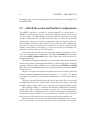
A system control coprocessor, CP0, which is incorporated into each µMPS2
processor, provides:
• Support for two processor operation modes; kernel-mode and user-mode.
• Support for exception handling. See Chapter 3.
• A processor Local Timer capable of generating interrupts.
• The resolution of all virtual addresses (i.e. virtual address translation); see
Chapter 4. CP0 provides support for two memory management processing
modes: Virtual memory (VM) off or VM on.
CP0 implements ten control registers. Five (Index, Random, EntryHi, EntryLo, and BadVAddr) are used to support virtual address translation. Two,
Cause and EPC are used by the exception/interrupt handling mechanism to indicate what type of exception and/or interrupt has occurred, PRID is a read-only
processor ID register (an integer i ∈ [0..15]), and Timer which implements the
processor’s Local Timer.
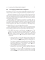
Finally, Status is a read/writable register that controls the usability of the coprocessors, the processor mode of operation (kernel vs. user), the address translation mode, and the interrupt masking bits.
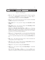
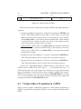
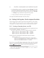
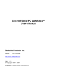
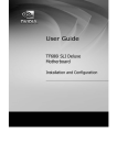
All bit fields in the Status register are read/writable. In particular:
5
31
28 27 26 25 24 23 22 21
CU
TE
VMVMVM
o p c
BE
V
16 15
8 7 6 5 4 3 2 1 0
Interrupt Mask (IM)
KU IE KU IE KU IE
o o p p c c
Figure 2.1: Status Register
• IEc: bit 0 - The “current” global interrupt enable bit. When 0, regardless
of the settings in Status.IM all external interrupts are disabled. When 1,
external interrupt acceptance is controlled by Status.IM.
• KUc: bit 1 - The “current” kernel-mode user-mode control bit. When Status.KUc=0 the processor is in kernel-mode.
• IEp & KUp: bits 2-3 - the “previous” settings of the Status.IEc and Status.KUc.
• IEo & KUo: bits 4-5 - the “previous” settings of the Status.IEp and Status.KUp - denoted the “old” bit settings.
These six bits; IEc, KUc, IEp, KUp, IEo, and KUo act as a 3-slot deep
KU/IE bit stack. Whenever an exception is raised the stack is pushed and
whenever an interrupted execution stream is restarted, the stack is popped.
See Section 3.2 for a more detailed explanation.
• IM: bits 8-15 - The Interrupt Mask. An 8-bit mask that enables/disables
external interrupts. When a device raises an interrupt on the i-th line, the
processor accepts the interrupt only if the corresponding Status.IM[i] bit is
on.
• BEV: bit 22 - The Bootstrap Exception Vector. This bit determines the
starting address for the exception vectors.
• VMc: Bit 24 - The “current” VM on/off flag bit. Status.VMc=0 indicates
that virtual memory translation is currently off.
• VMp: bit 25 - the “previous” setting of the Status.VMc bit.
• VMo: bit 26 - the “previous” setting of the Status.VMp bit - denoted the
“old” bit setting.
These three bits; VMc, VMp, and VMo act as a 3-slot deep VM bit stack.
Whenever an exception is raised the stack is pushed and whenever an inter-
6
CHAPTER 2. SYSTEM STRUCTURE AND OVERVIEW
rupted execution stream is restarted, the stack is popped. See Section 3.2
for a more detailed explanation.
• TE: Bit 27 - the processor Local Timer enable bit. A 1-bit mask that enables/disables the processor’s Local Timer. See Section 5.2.2 for more information about this timer.
• CU: Bits 28-31 - a 4-bit field that controls coprocessor usability. The bits
are numbered 0 to 3; Setting Status.CU[i] to 1 allows the use of the i-th
co-processor. Since µMPS2 only implements CP0 only Status.CU[0] is
writable; the other three bits are read-only and permanently set to 0.
Trying to make use of a coprocessor (via an appropriate instruction) without the corresponding coprocessor control bit set to 1 will raise a Coprocessor Unusable exception. In particular untrusted processes can be prevented from CP0 access by setting Status.CU[0]=0. CP0 is always accessible/usable when in kernel mode (Status.KUc=0), regardless of the value
of Status.CU[0].
Important Point: Since CP1 (the floating point co-processor) is not implemented, floating point instruction execution attempts generate a Coprocessor Unusable exception.
2.0.1 System Status at Boot/Reset Time
When µMPS2 is first turned on, or reset (see Chapter 9) only one processor
(PRID=0) is available; see Chapter 7 on how to startup any other needed processors. The initial processor’s CP0 is enabled (Status.CU[0]=1), VM is off
(Status.VMc=0), interrupts are disabled (Status.IEc=0), the Bootstrap Exception Vector is on (Status.BEV=1), the processor Local Timer is disabled (Status.TE=0 & Timer=0x0000.0000), and user-mode (Status.KUc=0) is off; i.e.
Status=0x1040.0000. The PC is set to the Bootstrap ROM code (0x1FC0.0000 see Section 4.1), and the $SP is set to 0x0000.0000. See Section 6.1 for a description of the actions of the Bootstrap ROM code.
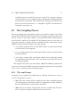
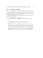
2.0.2 Guideposts to Understanding µMPS2
The details of the µMPS2 architecture are divided into four areas. The first is
exception processing which is described in Chapter 3. The second is memory
7
management/virtual address translation which is explained in Chapter 4. The details for interacting with all the devices supported by µMPS2 is found in Chapter
5 and the new instructions for processor management are described in Chapter 6.
There cannot be greater rudeness than to interrupt another in the current
of his discourse.
John Locke
3
Exception Handling
An exception is defined as a relatively infrequent event that interrupts the current
execution stream. There are four categories of exceptions:
• Program Traps (PgmTrap): These include the Address Error, Bus Error,
Reserved Instruction, Coprocessor Unusable, and Arithmetic Overflow exceptions.
• SYSCALL/Breakpoint (SYS/Bp): These include the System call and Breakpoint exceptions.
• TLB Management (TLB): These include the TLB-Modification, TLB-Invalid,
PTE-MISS, and Bad-PgTbl exceptions.
• Interrupts (Ints): This is for external device and Software Interrupt exceptions.
3.1 Exception Types
3.1.1 Program Traps (PgmTrap)
• Address Error (AdEL & AdES): This exception is raised whenever
8
3.1. EXCEPTION TYPES
9
– A load/store/instruction fetch of a word is not aligned on a word boundary.
– A load/store of a halfword is not aligned on a halfword boundary.
– A user-mode access is made to an address below 0x2000.0000 when
Status.VMc=0.
– A user-mode access is made to an address below 0x8000.0000 (ksegOS) when Status.VMc=1.
• Bus Error (IBE & DBE): This exception is raised whenever an access is
attempted on a non-existent physical memory location or when an attempt
is made to write onto ROM storage.
• Reserved Instruction (RI): This exception is raised whenever an instruction
is ill-formed, not recognizable, or is privileged and is executed while in
user-mode.
• Coprocessor Unusable (CpU): This exception is raised whenever an instruction requiring the use of or access to an uninstalled or currently unavailable coprocessor is executed. Since all µMPS2 control registers are implemented as part of CP0, access to these registers when Status.KUc=1 and
Status.CU[0]=0 will raise this exception. CP0 is always available when in
kernel-mode (Status.KUc=0).
• Arithmetic Overflow (Ov): This exception whenever an ADD or SUB instruction execution results in a 2’s-compliment overflow.
3.1.2 SYSCALL/Breakpoint (SYS/Bp)
These exceptions, denoted Sys and Bp respectively, are raised whenever a BREAK
or SYSCALL instruction is executed. These instructions are used by processes to
request operating system services.
3.1.3 TLB Management (TLB)
For all of these exceptions more details on the circumstances of when they are
raised can be found in Chapter 4.
• TLB-Modification (Mod): This exception is raised when on a write request a
“matching” entry is found, the entry is marked valid, but not dirty/writable.
CHAPTER 3. EXCEPTION HANDLING
10
• TLB-Invalid (TLBL & TLBS): This exception is raised whenever a “matching” entry is found but the entry is marked invalid.
• Bad-PgTbl (BdPT): This exception is raised during a TLB-Refill event and
the ROM-TLB-Refill handler determines that the
– address of the PTE is less than 0x2000.0000.
– address of the PTE is not word-aligned.
– PTE’s magic number is not 0x2A.
– address of the PTE + 4 + (8 * the PTE’s entry count) is greater than
RAMTOP.
See Section 4.3.4 for a more complete description of TLB-Refill events.
• PTE-MISS (PTMs): This exception is raised during a TLB-Refill event and
the ROM-TLB-Refill handler does not find a desired “matching” entry while
linearly searching the PgTbl. See Section 4.3.4 for a more complete description of TLB-Refill events.
3.1.4 Interrupts (Ints)
An interrupt, denoted Int, is an exception (usually) raised by a device external
to the processor. µMPS2 allows for 8 interrupt lines to be monitored, with each
line supporting a number of devices connected to it. Interrupt lines are numbered
0–7. A lower interrupt line indicates a higher servicing precedence for the devices
connected to that line. Only 5 interrupt lines are available for external devices.
Interrupt line 0 is reserved for inter-processor interrupts; see Chapter 7 for
more on µMPS2’s support for up to 16 processors. Line 1 is reserved for processor
Local Timer interrupts (Section 5.2.2), and line 2 is reserved for Interval Timer
interrupts (Section 5.2.1). Finally, interrupt lines 3–7 are for monitoring interrupts
from external devices.
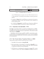
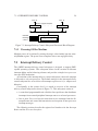
3.2 Processor Actions on Exception
Whenever an exception occurs there are a number of actions that the µMPS2 processor always takes. Furthermore, these actions are performed atomically. They
are:
3.2. PROCESSOR ACTIONS ON EXCEPTION
11
1. CP0 loads the Exception PC (EPC) CP0 register with the current PC value.
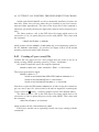
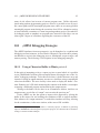
2. The exception cause code is set in Cause.ExcCode.
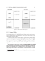
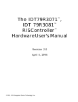
3. The VM and KU/IE stacks in the Status CP0 register are set/pushed in the
following manner:
Figure 3.1: VM and KU/IE Stack Push
Hence the processor always enters an exception handler in kernel-mode with
virtual memory turned off and with all interrupts disabled.
Additionally, the processor will also on:
• Address Error exceptions:
– Load the BadVAddr CP0 register with the offending address; this
register is used even if Status.VMc=0.
• Interrupt exceptions:
– Update the Cause.IP field bits to show on which lines interrupts are
pending.
• Coprocessor Unusable exceptions:
– Place the appropriate coprocessor number in the Cause.CE field.
• TLB-Modification, TLB-Invalid, PTE-MISS, and Bad-PgTbl exceptions (these
exceptions can only occur when Status.VMc=1):
– Load the BadVAddr CP0 register with the virtual address value that
failed translation.
CHAPTER 3. EXCEPTION HANDLING
12
– Load EntryHi.SEGNO and EntryHi.VPN with the SEGNO and VPN
from the virtual address that failed translation.
Finally, the PC is loaded with the address of one of two ROM-based exception handlers. One, located in the Bootstrap ROM code (0x1FC0.0180) is
used whenever Status.BEV=1. The other, located in the execution ROM code
(0x0000.0080) is used whenever Status.BEV=0. This allows for different exception handlers to be used during the OS bootstrapping process, Status.BEV=1, and
for regular processor execution, Status.BEV=0.
In summary, when an exception is raised, the processor performs a number of
steps atomically. These include a push operation on the KU/IE and VM stacks,
saving off the current PC, setting the exception code in Cause, possibly setting
some other CP0 registers (e.g. BadVAddr), and finally loading the PC with one
of two addresses depending on the setting of Status.BEV. What happens next is
up to the ROM exception handler whose address is placed in the PC.
The job of the execution (or non-Bootstrap) ROM exception handler (ROMExcpt handler) is to facilitate the “passing” of the handling of the exception to the
OS. Towards this end, the ROM-Excpt handler will atomically save off the current
processor state –store the contents of the processor’s registers into a given memory
location– and then load a new processor state –load the processor’s registers from
values stored at a given memory location.
3.2.1 Processor State
A processor state is defined as a 35 word block that contains the following registers:
• 1 word for the EntryHi CP0 register. This register contains the current
ASID (EntryHi.ASID).
• 1 word for the Cause CP0 register.
• 1 word for the Status CP0 register.
• 1 word for the PC (New Area) or EPC (Old Area) - the PC/EPC slot.
• 29 words for the GPR registers. GPR registers $0, $k0, and $k1 are excluded.
• 2 words for the HI and LO registers.
3.2. PROCESSOR ACTIONS ON EXCEPTION
13
Since there is no single non-interruptible processor instruction that loads a
processor state or stores a processor state, the ROM-Excpt handler stores and
loads processor states atomically by turning off interrupts and then individually,
register-by-register, first storing off the current processor state –the 35 above defined registers– and then loading these same 35 registers with new values.
Important Point: The current processor state (i.e. the current contents of the
above defined 35 processor registers) of the ROM-Excpt handler is the same state
the processor was in at the time the exception was raised except that that the
KU/IE and VM stacks have been pushed, the PC at the time of the exception
has been stored in the EPC, and Cause.ExcCode has been appropriately updated.
When the ROM-Excpt handler stores the processor state, the EPC is what is stored
in the PC/EPC slot. When the ROM-Excpt handler loads a new processor state
the contents of the PC/EPC slot is loaded into the PC.
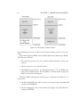
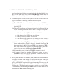
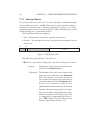
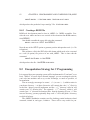
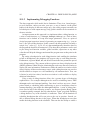
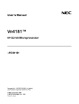
3.2.2 Old and New Processor State Areas
Figure 3.2: Old and New State Areas
The ROM-Excpt handler needs a location in memory to store the current processor state in addition to an address in memory from which to load a new processor state from. The first frame of physical RAM (located at 0x2000.0000), which
14
CHAPTER 3. EXCEPTION HANDLING
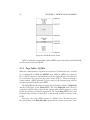
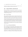
is called the ROM Reserved Frame is reserved for this purpose. The ROM Reserved Frame is also used to store process segment tables and provide stack space
for the execution ROM exception handler (ROM-Excpt handler) and the execution
ROM TLB-Refill event handler (ROM-TLB-Refill handler). See Section 4.3 for
more details about the segment tables stored in the ROM Reserved Frame.
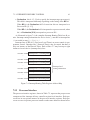
Figure 3.3: ROM Reserved Frame
Where the ROM-Excpt handler stores the current processor state in the ROM
Reserved Frame is dependent on the type of exception that occurred. The current
processor state is stored in either the Ints, TLB, SYS/Bp, or PgmTrap Old Area.
The processor registers are then loaded from the corresponding New Area by the
ROM-Excpt handler.
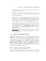
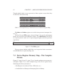
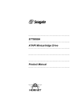
3.3. THE CAUSE CP0 REGISTER
15
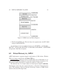
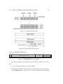
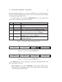
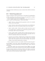
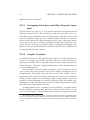
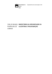
3.3 The Cause CP0 Register
31 30 29 28 27
BD
CE
16 15
8 7 6
Interrupts Pending (IP)
2 1 0
ExcCode
Figure 3.4: Cause CP0 Register
Cause is a CP0 register containing information about the current exception
and/or pending device interrupts. As described above it is set by the hardware at
the time the exception is raised and is stored as part of the current processor state
in the appropriate Old Area in the ROM Reserved Frame.
The Cause fields are all read-only, except Cause.IP[0] and Cause.IP[1], and
are defined as follows:
• ExcCode (bits 2-6): a 5-bit field that provides a code as to which exception
was raised.
• IP (bits 8-15): an 8-bit field indicating on which interrupt lines interrupts
are currently pending. If an interrupt is pending on interrupt line i, then
Cause.IP[i] is set to 1.
Important Point: Many interrupt lines may be active at the same time. Furthermore, many devices on the same interrupt line may be requesting service. Cause.IP is always up to date, immediately responding to external
(and internal) device events.
• CE (bits 28-29): A 2 bit field which indicates which coprocessor was illegally accessed when a Coprocessor Unusable exception is raised.
• BD (bit 31): This single bit indicates the last exception raised occurred in
a Branch Delay slot. µMPS2 faithfully simulates an R2/3000 as much as
possible. As described in Chapter 8.3 µMPS2 code is compiled using a
standard MIPS R2/3000 cross compiler. This compiler organizes the resultant machine code for a real MIPS R2/3000 processor which includes
an awareness of delayed loads and branch delay slots. Delayed loads and
branch delay slots are conventions/techniques used by fast RISC processors
to prevent pipeline slowdowns or stalls. (See “MIPS RISC Architecture”
by Gary Kane and Joe Heinrich, Prentice Hall, 1992 for more information.)
Since µMPS2 is a simulated processor, there are no pipeline stages nor overlapped instruction execution. Though delayed loads and branch delay slots
CHAPTER 3. EXCEPTION HANDLING
16
are present –from the compiler– they are correctly handled. Hence, the BD
bit can safely be ignored.
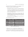
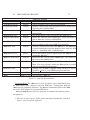
The 15 codes used in Cause.ExcCode are:
Number Code
0
Int
1
Mod
2
TLBL
3
TLBS
4
AdEL
5
AdES
6
IBE
7
DBE
8
Sys
9
Bp
10
RI
11
CpU
12
OV
13
BdPT
14
PTMs
Description
External Device Interrupt
TLB-Modification Exception
TLB Invalid Exception: on a Load instr. or instruction fetch
TLB Invalid Exception: on a Store instr.
Address Error Exception: on a Load or instruction fetch
Address Error Exception: on a Store instr.
Bus Error Exception: on an instruction fetch
Bus Error Exception: on a Load/Store data access
Syscall Exception
Breakpoint Exception
Reserved Instruction Exception
Coprocessor Unusable Exception
Arithmetic Overflow Exception
Bad Page Table
Page Table Miss
Table 3.1: Cause Register Status Codes
3.4 The Truth about ROM
As more fully described in Section 4.5, virtual address translation in general, and
TLB-Refill event handling in particular is dealt with cooperatively between the
physical hardware and the ROM-TLB-Refill handler. The physical hardware only
understands Cause.ExcCode values [0..12]. As described in Section 4.5, it is the
ROM-TLB-Refill handler that alters the value in the Cause.ExcCode, in the TLB
Old Area from either TLBL or TLBS, the code set by the physical hardware, to
either BdPT or PTMs as indicated.
Memory is like an orgasm. It’s a lot better if you don’t have to fake it.
Seymore Cray – on virtual memory
4
Memory Management
Since µMPS2 supports virtual memory, there are two views of the memory subsystem: physical and virtual. We start with the physical.
4.1 Physical Memory
The physical address space is divided into equal sized frames of 4KB each. Hence
a physical address has two components; a 20-bit Physical Frame Number or PFN,
and a 12-bit Offset into the frame. Physical addresses have the following format:
31
12 11
Physical Frame Number (PFN)
0
Offset
Figure 4.1: Physical Address Format
This means that µMPS2 can have up to 220 (or about a 1M) frames of memory.
The physical address space is the same under kernel-mode processing as under
user-mode processing except for one difference. As Figure 4.2 indicates, the first
217 (or about 128K) frames, which amounts to the first 0.5GB of memory can
only be accessed in kernel-mode. The processor must be in kernel-mode when
reading/writing any address in this range. An Address Error exception is raised
17
18
CHAPTER 4. MEMORY MANAGEMENT
Figure 4.2: The Physical Address Space
when attempting to access an address in this range while the processor is in usermode.
The installed physical RAM starts at 0x2000.0000 and continues up to RAMTOP. This area will hold
• The operating system code (text), global variables/structures (data), and
stack(s).
• The user processes’ text, data and stacks.
• The ROM Reserved Frame. As detailed in Section 3.2.2, the ROM code
needs some writable storage. The first 4KB (i.e. the first frame) of physical
RAM is reserved for this purpose.
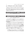
The first 0.5GB of the physical address space, as illustrated by Figure 4.3, is
reserved for
• The Execution ROM code. This read-only code segment starts at 0x0000.0000
and goes until ROMTOP.
• The device Registers. This read/writable area begins at 0x1000.0000 and
extends to DEVTOP.
4.2. VIRTUAL MEMORY IN µMPS2
19
Figure 4.3: ROM Areas and Device Regisers
• The Bootstrap ROM code. This read-only code segment starts at 0x1FC0.0000
and goes until BOOTTOP.
Any attempt to access an undefined memory area (ROMTOP – 0x1000.0000,
DEVTOP – 0x1FC0.0000, BOOTTOP – 0x2000.0000, and RAMTOP – 0xFFFF.FFFF
will generate a Bus Error exception.
4.2 Virtual Memory in µMPS2
µMPS2 implements a segmented-paged virtual memory (VM) scheme. Whether
VM is on or not is controlled by the Status.VMc bit.
Important Point: Addresses between 0x0000.0000 and 0x2000.0000 are always considered physical addresses, even when virtual memory is turned on. Virtual memory address translation is disabled for addresses in this range.
The first two bits of a virtual address are the Segment Number (SEGNO).
Virtual pages are the same size as physical frames, so the final 12-bits indicate an
offset. The remaining 18-bits indicate the Virtual Page Number or VPN. Virtual
addresses have the following format:
CHAPTER 4. MEMORY MANAGEMENT
20
31 30 29
Seg
No
0
12 11
Virtual Page Number (VPN)
Offset
Figure 4.4: Virtual Address Format
While 2-bits are used to designate the segment, µMPS2 only implements three
segments:
• Segment ksegOS (aka Segment 0). ksegOS is designated by SEGNO’s 00
and 01. This 2GB segment is for the OS text, data, stacks, as well as the
ROM code and device registers that sit at the beginning of this segment.
When Status.VMc=1 (since talking about segments when virtual memory
is turned off doesn’t make any sense) any access to this segment in usermode will generate an Address Error exception.
Important Point: When VM is off (Status.VMc=0) only the first 0.5GB of
the address space is protected automatically by the hardware from usermode access. When VM is on (Status.VMc=1), this protection extends
through all of ksegOS.
• Segment kUseg2 (aka Segment 2). kUseg2 is designated by SEGNO=10.
This 1GB virtual address space is for the use of user-mode processes.
• Segment kUseg3 (aka Segment 3). kUseg3 is designated by SEGNO=11.
This 1GB virtual address space is for the use of user-mode processes.
As part of its VM implementation, µMPS2 assigns to each process a 6-bit
identifier; hence µMPS2 only allows up to 2 6 = 64 concurrent processes. To
reflect the fact that each of these processes will run in its own virtual address
space this identifier is called the Address Space Identifier (ASID). The “current”
ASID is part of the processor state and is stored in EntryHi.ASID. See Section
6.3.1 for a description of the special kernel-mode instructions that support the
reading and writing of the EntryHi CP0 register.
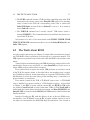
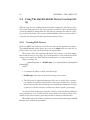
4.3 Virtual Address Translation in µMPS2
There are three primary components involved in virtual address translation in
µMPS2; segment tables, page tables (PgTbl’s), and a translation lookaside buffer
(TLB).
4.3. VIRTUAL ADDRESS TRANSLATION IN µMPS2
21
Figure 4.5: The Virtual Address Space
4.3.1 Segment Tables
As discussed in Section 3.2.2, the ROM Reserved Frame contains some data structures the ROM routines access/manipulate. One of these data structures is the
segment tables for all 64 ASID’s.
As shown in Figure 4.6 this frame contains a 0x300 byte area which µMPS2
expects to contain a 64×3 array of page table (PgTbl) pointers. There are 3 PgTbl
pointers for each ASID; one each for ksegOS, kUseg2, and kUseg3. Since µMPS2
only supports three segments, a µMPS2 segment table need only contain three
entries. Each entry consists solely of the address of the PgTbl associated with that
segment.
When translating a virtual address, µMPS2 uses EntryHi.ASID and the SEGNO
of the virtual address to be translated as the indices into this table to determine the
address of the indicated PgTbl. (Though kUseg2 is called Segment 2, its page
table addresses are in column 1, while Segment 3’s page table addresses are found
in column 2.)
Important Point: The PgTbl addresses used during address translation are physical addresses.
22
CHAPTER 4. MEMORY MANAGEMENT
Figure 4.6: ROM Reserved Frame
PgTbl’s, unlike the segment tables which µMPS2 expect to be found at 0x2000.00500,
can be located anywhere in RAM.
4.3.2 Page Tables - PgTbl’s
While the segment table is organized as an ordered 2-dimensional array, indexed
by a combination of ASID and SEGNO, page tables in µMPS2 are unordered
lists. A PgTbl consists of a special header word, the PgTbl-Header Word followed
by an unordered list (array) of page table entries (PTE’s). When translating a
virtual address, µMPS2 performs a linear search of the indicated page table to
find the entry describing the given VPN.
The PgTbl-Header Word has two fields; the PgTbl-Magic Number (MagicNO)
and the PgTbl-Entry Count (EntryCNT). The 8-bit MagicNO field is used to
verify that a PgTbl address found in the segment table actually points to a valid
PgTbl. It will always contain the value 0x2A. The 20-bit EntryCNT field is used
to bound linear searches of the PgTbl; it indicates the number of entries in the
PgTbl.
Each page table entry (PTE) consists of a double word. The first word has
the same format as the EntryHi CP0 register and the second word has the same
4.3. VIRTUAL ADDRESS TRANSLATION IN µMPS2
23
Figure 4.7: Segment Table Format
Figure 4.8: Page Table (PgTbl) Format
format as the EntryLo CP0 register.
31 30 29
Seg
No
6 5
12 11
Virtual Page Number (VPN)
ASID
Figure 4.9: EntryHi CP0 Control Register
All of these fields have been defined except the N, D, V, and G access control
bits.
• N - the non-cacheable bit: Not used in µMPS2.
• D - Dirty bit: This bit is used to implement memory protection mechanisms.
When EntryLo.D=0, a write access to a location in the physical frame will
0
24
CHAPTER 4. MEMORY MANAGEMENT
31
12 11 10 9 8 7
Physical Frame Number (PFN)
N D V G
Figure 4.10: EntryLo CP0 Control Register
cause a TLB-Modification exception to be raised. This bit therefore acts as
a “write protection” bit, allowing for the realization of memory protection
schemes.
• V - Valid bit: If EntryLo.V=1, this PTE entry is considered valid, otherwise
a TLB-Invalid exception is raised. This bit allows for the construction of
memory paging schemes.
• G - Global bit: If EntryLo.G=1, the PTE entry will match any ASID with
the corresponding VPN. This bit allows for memory sharing schemes.
4.3.3 Translation Lookaside Buffer - TLB
The TLB is an associative memory or cache, that can hold between 4–64 PTE’s.
The µMPS2 interface allows one to define the size of the TLB at boot/reset time;
see Chapter 9 for a description on how to set the TLB size. The current size of the
TLB is denoted as TLBSIZE.
By utilizing a cache of recently used PTE’s, µMPS2’s virtual address translation mechanism can avoid making multiple memory accesses for each translation
operation; obtaining the PgTbl address and linearly searching the indicated PgTbl
for a matching entry.
4.3.4 How Virtual Address Translation Works in µMPS2
Virtual address to physical address translation proceeds as follows:
1. The ASID for this translation is EntryHi.ASID.
2. If the virtual address to be translated is in ksegOS and Status.KUc=1 (i.e.
User-mode) an Address Error exception is raised. Note: Address translation
is disabled for all addresses below 0x2000.0000.
3. All TLB entries are simultaneously searched for a matching PTE. A match
is defined as an entry in the TLB whose SEGNO and VPN are the same as
0
4.3. VIRTUAL ADDRESS TRANSLATION IN µMPS2
25
those from the virtual address to be translated and either the global bit is on
(G=1) or the ASID of the entry matches EntryHi.ASID. If more than one
TLB entry matches, the highest numbered matching TLB entry is used.
4. If no matching entry is found, a TLB-Refill event occurs. A TLB-Refill event
triggers a search for a matching PTE in the indicated PgTbl.
(a) EntryHi.ASID and the virtual address to be translated’s SEGNO are
used as indices into the segment table to acquire the address of the
desired PgTbl.
(b) The PgTbl is validated as being well-formed and well-located. If any
of the following conditions are true than a Bad-PgTbl exception is
raised.
•
•
•
•
If the address of the PgTbl is less than 0x2000.0000.
If the address of the PgTbl is not word-aligned.
If the PgTbl’s magic number is not 0x2A.
If the address of the PgTbl + 4 + (8 * the PgTbl’s entry count) is
greater than RAMTOP.
(c) A linear search of the PgTbl is made until either a matching entry is
found or the end of the PgTbl is detected. A match is defined as the
first entry found in the PgTbl whose VPN is the same as the VPN in
the virtual address to be translated and either the entry’s global bit is
on (G=1) or the entry’s ASID matches EntryHi.ASID.
(d) If no matching entry is found a PTE-MISS exception is raised.
(e) If a match is found the matching PTE entry is written into one of
TLBSIZE-1 TLB slots selected at random. The first TLB slot, slot
0, is never used during a TLB-Refill event.
5. At this point either there is a matching PTE (either found during the initial
associative search, or found during the linear search and then written into
the TLB) or an exception has been raised (either an Address Error, BadPgTbl, or PTE-MISS exception). If there is a matching TLB entry then the
V and D control bits of the matching PTE are checked respectively. If no
TLB-Invalid or TLB-Modification exception is raised, the physical address
is constructed by concatenating the Offset from the virtual address to be
translated to the PFN from the matching PTE.
CHAPTER 4. MEMORY MANAGEMENT
26
4.4 CP0 Registers used in Address Translation
CP0 implements five registers used to support virtual address translation.
The contents of the TLB can be modified by writing values into the CP0 EntryHi and EntryLo registers and issuing either the TLB-Write-Index (TLBWI) or
TLB-Write-Random (TLBWR) CP0 instruction. Which slot in the TLB the entry
is written into is determined by which instruction is used and the contents of either
the Random or Index CP0 register.
31
13
8 7
0
TLB Index
Figure 4.11: Random CP0 Control Register
31 30
P
8 7
13
Physical Frame Number (PFN)
TLB Index
Figure 4.12: Index CP0 Control Register
Both the Random and the Index CP0 registers have a 6-bit TLB-Index field
which addresses one of the TLBSIZE slots in the TLB. The Index register is a
read/writable register. When a TLBWI instruction is executed, the contents of
the EntryHi and EntryLo CP0 registers are written into the slot indicated by
Index.TLB-Index.
The Random register is a read-only register used to index the TLB randomly;
allowing for more effective TLB-refiling schemes. Random.TLB-Index is initialized to TLBSIZE-1 and is automatically decremented by one every processor cycle until it reaches 1 at which point it starts back again at TLBSIZE-1.
This leaves one TLB “safe” entry (entry 0) which cannot be indexed by Random.
When a TLBWR instruction is executed, the contents of the EntryHi and EntryLo CP0 registers are written into the slot indicated by Random.TLB-Index.
(µMPS2’s TLB-Refill algorithm uses TLBWR to populate the TLB.)
Three other useful CP0 instructions associated with the TLB are the TLB-Read
(TLBR), TLB-Probe (TLBP), and the TLB-Clear (TLBCLR) commands.
• The TLBR command places the TLB entry indexed by Index.TLB-Index
into the EntryHi and EntryLo CP0 registers. Note, that this instruction
has the potentially dangerous affect of altering the value of EntryHi.ASID.
0
4.5. THE TRUTH ABOUT ROM
27
• The TLBP command initiates a TLB search for a matching entry in the TLB
that matches the current values in the EntryHi CP0 register. If a matching
entry is found in the TLB the corresponding index value is loaded into
Index.TLB-Index and the Probe bit (Index.P) is set to 0. If no match is
found, Index.P is set to 1.
• The TLBCLR command zero’s out the “unsafe” TLB entries; entries 1
through TLBSIZE-1 This command effectively invalidates the current contents of the TLB cache.
See Sections 6.3.1 and 6.3.2 for more details on the TLBWI, TLBWR, TLBR,
TLBP, TLBCLR CP0 instructions and how to access the EntryHi, EntryLo, and
Index CP0 registers.
4.5 The Truth About ROM
As with exception processing (see Chapter 3) virtual address translation in general
and TLB-Refill events in particular are dealt with in a cooperative manner. The
CP0 coprocessor performs some of the tasks while the ROM code performs some
others.
Virtual address translation begins with CP0 checking the virtual address to be
translated for illegal access to ksegOS; i.e. when Status.KUc=0. If the access is
illegal, CP0 raises an Address Error exception.
If no Address Error exception was raised, CP0 performs an associative search
of the TLB. If a match is found, as described above, the matching entry’s control
bits (Vand D) are checked. At this point either an exception (TLB-Invalid or TLBModification) is raised due to the setting of the matching entry’s control bits or a
physical address is constructed.
If no match is found in the TLB, a TLB-Refill event occurs. A TLB-Refill
event is handled in a manner similar to a TLB-Invalid exception. As described
in Chapter 3, the EPC is loaded with the current PC, the KU/IE & VM stacks
are pushed, Cause.ExeCode is loaded with either TLBL or TLBS, BadVAddr is
loaded with the virtual address that failed translation, and EntryHi.SEGNO and
EntryHi.VPN are loaded with the SEGNO and VPN from the virtual address that
failed translation.
Instead of loading the PC with the address of one of the two ROM exception handlers, on a TLB-Refill event, the PC is loaded with the address of one of
two different event handlers, the ROM TLB-Refill Event handlers. One, located in
28
CHAPTER 4. MEMORY MANAGEMENT
the bootstrap ROM code (0x1FC0.0100) is used whenever Status.BEV=1. The
other, located in the execution ROM code (0x0000.0000) is used whenever Status.BEV=0. This allows for different TLB-Refill event handlers to be used during
the OS bootstrapping process, Status.BEV=1, and for regular processor execution, Status.BEV=0.
The execution (or non-Bootstrap) ROM TLB-Refill event handler (ROM-TLBRefill handler) begins by looking up the address of the indicated PgTbl in the segment table. The PgTbl is then validated as being well-formed and well-located.
Finally, the ROM-TLB-Refill handler searches the PgTbl for a matching PTE, and
if found copies the PTE into a randomly selected slot in the TLB. The matching
entry is first copied into the EntryHi and EntryLo CP0 registers then a random
TLB entry is filled as a result of issuing a TLBWR command. To preserve the
current value of EntryHi.ASID, this field is saved off before the TLB is updated
and restored immediately afterwards.
If the ROM-TLB-Refill handler found a match and wrote it into the TLB, the
event handler will conclude by returning processor control to the interrupted execution stream. In one atomic step, the KU/IE & VM stacks are popped and the
address in the EPC is placed in the PC. (The ROM-TLB-Refill handler essentially executes the Return From Exception (RFE) µMPS2 assembler instruction.
See Chapter 6 for more about popping the KU/IE & VM stacks and the RFE
instruction.) Execution now continues with a repeated attempt to translate the
virtual address that generated the TLB-Refill event in the first place. This time
CP0 will find a matching PTE in the TLB and will either correctly construct the
translated physical address or it’ll generate a TLB-Invalid or TLB-Modification
exception - which will then “invoke” the ROM-Excpt handler to pass up the exception handling to the OS.
The other case is that the ROM-TLB-Refill handler discovered that either a
Bad-PgTbl or PTE-MISS exception needs to occur. In both of these cases the
ROM-TLB-Refill handler performs the same “passing up” actions as the ROMExcpt handler; save the current state in the TLB Old Area and load the processor
with the state in the TLB New Area. After the current state has been stored, and
immediately prior to the loading of the new state, the ROM-TLB-Refill handler
alters the Cause.ExcCode in the TLB Old Area from TLBL or TLBS (set by CP0
when the TLB-Refill event was raised) to either Bad-PgTbl or PTE-MISS appropriately.
Television is a device that permits people who haven’t anything to do to
watch people who can’t do anything.
Fred Allen
5
Device Interfaces
µMPS2 supports five different classes of external devices: disk, tape, network
card, printer and terminal. Furthermore, µMPS2 can support up to eight instances
of each device type. Each single device is operated by a controller. Controllers
exchange information with the processor via device registers; special memory
locations.
A device register is a consecutive 4-word block of memory. By writing and
reading specific fields in a given device register, the processor may both issue
commands and test device status and responses.
µMPS2 implements the full-handshake interrupt-driven protocol. Specifically:
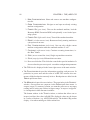
1. Communication with device i is initiated by the writing of a command code
into device i’s device register.
2. Device i’s controller responds by both starting the indicated operation and
setting a status field in i’s device register.
3. When the indicated operation completes, device i’s controller will again set
some fields in i’s device register; including the status field. Furthermore,
device i’s controller will generate an interrupt exception by asserting the
appropriate interrupt line. The generated interrupt exception informs the
29
CHAPTER 5. DEVICE INTERFACES
30
processor that the requested operation has concluded and that the device
requires its attention.
4. The interrupt is acknowledged by writing the acknowledge command code
in device i’s device register.
5. Device i’s controller will de-assert the interrupt line and the protocol can
restart. For performance purposes, writing a new command after the interrupt is generated will both acknowledge the interrupt and start a new
operation immediately.
The device registers are located in low-memory starting at 0x1000.0000. As
explained in Chapter 4, regardless of Status.VMc, all addresses between 0x1000.0000
and DEVTOP are interpreted as physical addresses. Furthermore, the device registers can only be accessed when Status.KUc=0.
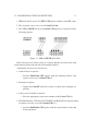
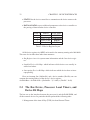
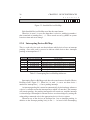
The following table details the correspondence between device class/type and
interrupt line.
Interrupt Line #
0
1
2
3
4
5
6
7
Device Class
Inter-processor interrupts
Processor Local Timer
Bus (Interval Timer)
Disk Devices
Tape Devices
Network (Ethernet) Devices
Printer Devices
Terminal Devices
Table 5.1: Interrupt Line and Device Class Mapping
Some important issues relating to device management:
• Since there are multiple interrupt lines, and multiple devices attached to the
same interrupt line, at any point in time there may be multiple interrupts
pending simultaneously; both across interrupt lines and on the same interrupt line.
5.1. DEVICE REGISTERS
31
• The lower the interrupt line number, the higher the priority of the interrupt.
Note how fast/critical devices (e.g. disk devices) are attached to a high
priority interrupt line while slow devices are attached to the low priority
interrupt lines.
• Interrupt lines 3–7 are used for external devices. Interrupt lines 0–2 are for
internally generated interrupts.
• Disk and tape devices support Direct Memory Access (DMA); that is through
cooperation with the bus, these devices are able to transfer whole blocks of
data to/from memory from/to the device. Data blocks must be both wordaligned and of multiple-word in size. µMPS2 supports any number of concurrent DMA operations; each on a different device. Care must be taken to
prevent simultaneous DMA operations on the same chunk of memory.
• After an operation has begun on a device, its device register “freezes” –
becomes read-only – and will not accept any other commands until the operation completes.
• Any device register for an uninstalled device is “frozen” – set to zero – and
subsequent writes to the device register have no effect.
• Device registers use only physical addresses; this includes addresses used
in DMA operations.
• Each external device in µMPS2 is identified by the interrupt line it is attached to and its device number; an integer in [0..7]. µMPS2 limits the
number of devices per interrupt line to eight.
• For performance reasons, devices in the same class are, by default, attached
to the same interrupt line.
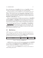
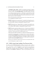
5.1 Device Registers
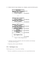
All external devices share the same device register structure.
While each device class has a specific use and format for these fields, all device
classes, except terminal devices, use:
• COMMAND to allow commands to be issued to the device controller.
32
CHAPTER 5. DEVICE INTERFACES
• STATUS for the device controller to communicate the device status to the
processor.
• DATA0 & DATA1 to pass additional parameters to the device controller or
the passing of data from the device controller.
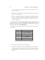
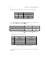
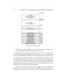
Field #
Address
Field Name
0
(base) + 0x0
STATUS
1
(base) + 0x4 COMMAND
2
(base) + 0x8
DATA0
3
(base) + 0xc
DATA1
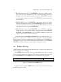
Table 5.2: Device Register Layout
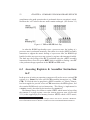
All 40 device registers in µMPS2 are located in low memory starting at 0x1000.0000.
This area also includes three other data structures:
• Bus Register Area: for system status information and the “bus device register.”
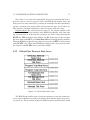
• Installed Devices Bit Map: which indicates which devices are actually installed and where.
• Interrupting Devices Bit Map: which indicates which devices have an interrupt pending.
Given an interrupt line (IntLineNo) and a device number (DevNo) one can
compute the starting address of the device’s device register:
devAddrBase = 0x1000.0050 + ((IntlineNo - 3) * 0x80) + (DevNo * 0x10)
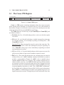
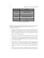
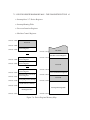
5.2 The Bus Device, Processor Local Timers, and
Device Bit Maps
The bus acts as the interface between the processor(s) and the RAM, ROM, and
all the external devices. In particular the bus performs the following tasks:
1. Management of the time of Day (TOD) clock and Interval Timer.
5.2. THE BUS DEVICE, PROCESSOR LOCAL TIMERS, AND DEVICE BIT MAPS33
Figure 5.1: Device Registers Area
2. Arbitration among the interrupt lines, the devices attached to each interrupt
line and the device registers.
3. Repository of basic system information.
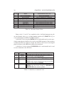
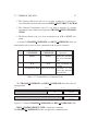
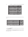
5.2.1 Bus Register Area
The bus register area is a 10 word area containing
The first 6 words/fields are read-only and are set at system boot/reset time.
34
CHAPTER 5. DEVICE INTERFACES
Physical Address
Field Name
0x1000.0000
RAM Base Physical Address
0x1000.0004
Installed RAM Size
0x1000.0008
Exec. ROM Base Physical Address
0x1000.000c
Installed Exec. ROM Size
0x1000.0010
Bootstrap ROM Base Physical Address
0x1000.0014
Installed Bootstrap ROM Size
0x1000.0018
Time of Day Clock - High
0x1000.001c
Time of Day Clock - Low
0x1000.0020
Interval Timer
0x1000.0024
Time Scale
Table 5.3: Bus Register Area
RAMTOP is calculated by adding the RAM base physical address to the installed
RAM size. ROMTOP and BOOTTOP are calculated in similar fashion.
The other four words are:
1. Time Scale: A read-only field, set at system boot/reset time which indicates
the number of clock ticks that will occur in a microsecond. As described in
Chapter 9 one may adjust the processor clock speed. When the processor
speed is set to 1MHz, the Time Scale is set to 1. This field is used to help
make accurate timing computations.
2. Time of Day Clock (TOD): This read-only doubleword register (split into
its high and low word parts) is set by µMPS2 circuitry to zero at system
boot/reset time. It is by incremented by one after every processor cycle;
i.e. a clock tick. Each µMPS2 machine instruction is designed to take one
processor cycle to execute.
3. Interval Timer: A read/writable unsigned word that is decremented by one
every processor cycle and is set by µMPS2 circuitry to 0xFFFF.FFFF at
system boot/reset time. The Interval Timer will generate an interrupt on
interrupt line 2 whenever it makes the 0x0000.0000 ⇒ 0xFFFF.FFFF transition.
This is the only device attached to interrupt line 2, hence any interrupt on
this line may be assumed to be associated with the Interval Timer. Interval
5.2. THE BUS DEVICE, PROCESSOR LOCAL TIMERS, AND DEVICE BIT MAPS35
Timer interrupts are acknowledged by writing a new value into the Interval
Timer register.
5.2.2 Processor Local Timer
Similar in behavior to the Interval Timer is the processor Local Timer. Each processor, implemented as part of its CP0 coprocessor has its own local timer; the
CP0 Timer register which is decremented by one every processor clock cycle.
Like the Interval Timer, processor Local Timers can be read and written - See
Section 6.3.2 for details. A processor Local Timer will generate an interrupt on
interrupt line 1 whenever it makes the 0x0000.0000 ⇒ 0xFFFF.FFFF transition.
This is the only device attached to interrupt line 1, hence any interrupt on this
line may be assumed to be associated with the processor Local Timer. Processor
Local Timer interrupts are acknowledged by writing a new value into the Interval
Timer register.
Unlike the Interval Timer, a processor Local Timer can be disabled. Whether
this timer is enabled or not is determined by the Status.TE (Timer Enable) bit.
When Status.TE=0 the local timer will not generate interrupts. Note, however,
that it is implementation dependent whether the timer will continue to run/decrement
when Status.TE=0.
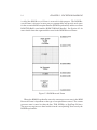
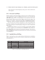
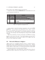
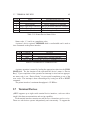
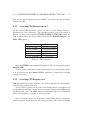
5.2.3 Installed Devices Bit Map
This is a read-only five word area that indicates which devices are attached to
which interrupt line. One word each is reserved to describe the devices attached
to interrupt lines 3–7.
Word # Physical Address
0
0x1000.0028
1
0x1000.002C
2
0x1000.0030
3
0x1000.0034
4
0x1000.0038
Field Name
Interrupt Line 3 Installed Devices Bit Map
Interrupt Line 4 Installed Devices Bit Map
Interrupt Line 5 Installed Devices Bit Map
Interrupt Line 6 Installed Devices Bit Map
Interrupt Line 7 Installed Devices Bit Map
Table 5.4: Installed Devices Bit Map Addresses
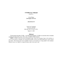
CHAPTER 5. DEVICE INTERFACES
36
31
8 7 6 5 4 3 2 1 0
Figure 5.2: Installed Devices Bit Map
Each Installed Devices Bit Map word has the same format:
When bit i in word j is set to one then there is a device, with device number i
that is attached to interrupt line j + 3. These words are set by µMPS2 at system
boot/reset time and never change.
5.2.4 Interrupting Devices Bit Map
This is a read-only five word area that indicates which devices have an interrupt
pending. One word each is reserved to indicate which devices have interrupts
pending on interrupt lines 3–7.
Word #
0
1
2
3
4
Physical Address
0x1000.003C
0x1000.0040
0x1000.0044
0x1000.0048
0x1000.004C
Field Name
Interrupt Line 3 Interrupting Devices Bit Map
Interrupt Line 4 Interrupting Devices Bit Map
Interrupt Line 5 Interrupting Devices Bit Map
Interrupt Line 6 Interrupting Devices Bit Map
Interrupt Line 7 Interrupting Devices Bit Map
Table 5.5: Interrupting Devices Mit Map Addresses
Interrupting Devices Bit Map words have the same format as Installed Device
Bit Map words; Figure 5.2. When bit i in word j is set to one then device i
attached to interrupt line j + 3 has a pending interrupt.
An interrupt pending bit is turned on automatically by the hardware whenever
a device’s controller asserts the interrupt line to which it is attached. The interrupt
will remain pending –the pending interrupt bit will remain on– until the interrupt
is acknowledged. Interrupts for external devices are acknowledged by writing the
acknowledge command code in the appropriate device’s device register.
Whenever any of the devices on interrupt line i has an interrupt pending, in
addition to the interrupt pending bit(s) in the i − 3rd word of the Interrupting
5.3. DISK DEVICES
37
Devices Bit Map being on, Cause.IP[i] will also be on. Cause.IP[i] will only be
off when none of the devices attached to line i have a pending interrupt.
Interrupt pending bits, both in Cause.IP and in the Interrupting Devices Bit
Map get automatically turned on in response to device controllers asserting interrupt lines. The interrupt masking flags, Status.IEc and Status.IM, are used to
determine if a pending interrupt actually generates an interrupt exception or not.
A pending interrupt on interrupt line i will generate an interrupt exception if both
Status.IEc and Status.IM[i] are set to 1.
There are no Interrupting Devices Bit Maps for interrupt lines 0–2. Cause.IP[2]=1
should be interpreted as signalling a pending interrupt from the Interval Timer,
while Cause.IP[0]=1 or Cause.IP[1]=1 indicate a pending software interrupt. As
discussed above, an Interval Timer interrupt is acknowledged by writing a new
value into the Interval Timer register. A software interrupt is acknowledged by directly writing the Cause register directly to set Cause.IP[0]=0 or Cause.IP[1]=0.
Important Point: Many interrupt lines may be active at the same time. Furthermore, many devices on the same interrupt line may be requesting service.
Cause.IP and the Interrupting Devices Bit Map are always up to date, immediately responding to external device events.
5.3 Disk Devices
µMPS2 supports up to eight DMA supporting read/writable hard disk drive devices. All µMPS2 disk drives have a blocksize equal to the µMPS2 framesize
of 4KB. Each installed disk drive’s device register DATA1 field is read-only and
describes the physical characteristics of the device’s geometry.
31
16 15
MAXCYL
8 7
MAXHEAD
0
MAXSECT
Figure 5.3: Disk Device DATA1 Field
µMPS2 disk drives can have up to 65536 cylinders/track, addressed [0..MAXCYL1]; 256 heads (or track surfaces), addressed [0..MAXHEAD-1]; and 256 sectors/track, addressed [0..MAXSECT-1]. Each 4KB physical disk block (or sector) can be addressed by specifying its coordinates: (cyl, head, sect).
A disk drive’s device register STATUS field is read-only and will contain one
of the following status codes:
CHAPTER 5. DEVICE INTERFACES
38
Code
Status
0
Device Not Installed
1
Device Ready
2
Illegal Operation Code Error
3
Device Busy
4
Seek Error
5
Read Error
6
Write Error
7
DMA Transfer Error
Possible Reason for Code
Device not installed
Device waiting for a command
Device presented unknown command
Device executing a command
Illegal parameter/hardware failure
Illegal parameter/hardware failure
Illegal parameter/hardware failure
Illegal physical address/hardware failure
Table 5.6: Disk Drive Status Codes
Status codes 1, 2, and 4–7 are completion codes. An illegal parameter may be
an out of bounds value (e.g. a cylinder number outside of [0..(MAXCYL-1)]), or
a non-existent physical address for DMA transfers.
A disk drive’s device register DATA0 field is read/writable and is used to specify the starting physical address for a read or write DMA operation. Since memory
is addressed from low addresses to high, this address is the lowest word-aligned
physical address of the 4KB block about to be transferred.
A disk drive’s device register COMMAND field is read/writable and is used
to issue commands to the disk drive.
Code
0
1
2
3
Command
RESET
ACK
SEEKCYL
READBLK
4
WRITEBLK
Operation
Reset the device and move the boom to cylinder 0
Acknowledge a pending interrupt
Seek to the specified CYLNUM
Read the block located at (HEADNUM, SECTNUM) in the current cylinder and copy it into RAM
starting at the address in DATA0
Copy the 4KB of RAM starting at the address in
DATA0 into the block located at (HEADNUM,
SECTNUM) in the current cylinder
Table 5.7: Disk Drive Command Codes
5.4. TAPE DEVICES
39
The format of the COMMAND field, as illustrated in Figure 5.4, differs depending on which command is to be issued:
31
24 23
16 15
HEADNUM
8 7
SECTNUM
CYLNUM
0
READBLK
WRITEBLK
SEEKCYL
RESET
ACK
Figure 5.4: Disk Device COMMAND Field
A disk operation is started by loading the appropriate value into the COMMAND field. For the duration of the operation the device’s status is “Device
Busy.” Upon completion of the operation an interrupt is raised and an appropriate status code is set; “Device Ready” for successful completion or one of the
error codes. The interrupt is then acknowledged by issuing an ACK or RESET
command.
Disk device performance, because both read and write operations are DMAbased, strongly depends on the system clock speed. While read/write throughput
may reach MB’s/sec in magnitude, the disk hardware operations remain in the
millisecond range.
5.4 Tape Devices
µMPS2 supports up to eight tape-removable, DMA supporting, read-only tape devices. All µMPS2 tape devices support a blocksize of 4KB. Each installed tape
device’s register DATA1 field is read-only and describes the current marker under
the tape head when the device is idle.
A tape starts with a TS marker and ends with an EOT marker. It may be
viewed as a collection of blocks, delimited by EOB markers, which are divided
into files, delimited by EOF markers. An EOF marker acts as the EOB marker
for the last block of the file and the EOT marker act as the EOF (and therefore
also an EOB) marker for the last file on the tape.
CHAPTER 5. DEVICE INTERFACES
40
Code
0
1
2
3
Marker
EOT
EOF
EOB
TS
Meaning
End of Tape
End of File
End of Block
Tape Start
Table 5.8: Tape Marker Codes
When there is no tape cartridge loaded into the tape device, the DATA1 field
will contain the EOT marker, and the STATUS field will contain the Device
Ready code. Since there is no tape cartridge present, the COMMAND field,
though, will not accept any commands. Only when a tape is loaded does the device “wake up” and begin accepting commands. When a tape cartridge is loaded,
the tape device rewinds the cartridge back to the TS marker.
A tape drive’s device register STATUS field is read-only and will contain one
of the following status codes:
Code
Status
0
Device Not Installed
1
Device Ready
2
Illegal Operation Code Error
3
Device Busy
4
Skip Error
5
Read Error
6
Back 1 Block Error
7
DMA Transfer Error
Possible Reason for Code
Device not installed
Device waiting for a command
Device presented unknown command
Device executing a command
Illegal command/hardware failure
Illegal command/hardware failure
Illegal command/hardware failure
Illegal physical address/hardware failure
Table 5.9: Tape Drive Status Codes
Status codes 1, 2, and 4–7 are completion codes. An illegal parameter may be
an attempt to read beyond the EOT marker or a non-existent physical address for
DMA transfers.
A tape drive’s device register DATA0 field is read/writable and is used to
specify the starting physical address for a DMA read operation. Since memory
is addressed from low addresses to high, this address is the lowest word-aligned
5.5. NETWORK (ETHERNET) ADAPTERS
41
physical address of the 4 KB block about to be transferred.
A tape drive’s device register COMMAND field is read/writable and is used
to issue commands to the tape drive.
Code Command
0
RESET
1
ACK
2
SKIPBLK
3
READBLK
4
BACKBLK
Operation
Reset the device and rewind the tape to TS marker
Acknowledge a pending interrupt
Forward the tape up to the next EOB/EOT
Read the current block up to the next EOB/EOT
marker and copy it into RAM starting at the address
in DATA0
Rewind the tape to the previous EOB/EOT marker
Table 5.10: Tape Drive Command Codes
A tape operation is started by loading the appropriate value into the COMMAND field. For the duration of the operation the device’s status is “Device
Busy.” Upon completion of the operation an interrupt is raised and an appropriate status code is set; “Device Ready” for successful completion or one of the
error codes. The interrupt is then acknowledged by issuing an ACK or RESET
command.
Tape device performance, because read operations are DMA-based, strongly
depends on the system clock speed. Tape read throughput can range from 2
MB/sec when the processor clock is set at 1 MHz, to over 4 MB/sec when the
processor clock is bumped up to 99 MHz.
5.5 Network (Ethernet) Adapters
µMPS2 supports up to eight DMA supporting network (i.e. Ethernet) adapters.
Though these devices are DMA-based, they are not block devices. Network
adapters operate at the byte level and transfer into/out of memory only the amount
of data called for. Since packets on a network typically follow standard MTU
sizes, this data should never exceed (by much) 1500 bytes.
Network adapters share some characteristics with terminal devices; they are
simultaneously both an input device and an output device. As an output device,
CHAPTER 5. DEVICE INTERFACES
42
network adapters behave like other peripherals: a write command is issued and
when the write (i.e. transmit) is completed, an interrupt is generated.
For packet receipt, there are two modes of operation:
• Interrupt Enabled: Whenever a packet arrives, an interrupt is generated this interrupt is not the result of an earlier command. After ACK’ing this
interrupt one issues a READNET command to read the packet. When the
read is completed, another interrupt is generated, which itself must also be
ACK’ed. In Interrupt Enabled mode, each incoming packet, when successfully read, is a two-interrupt sequence.
• Interrupt Disabled: When packets arrive, no interrupt is generated. The
network adapter must be polled to determine if a packet is available. The
READNET command is non-blocking, and returns 0 if there is no packet to
be read. The READNET command will still generate an interrupt, which
must be ACK’ed, upon its conclusion.
A network adapter’s device register STATUS field is read-only and will contain one of the following status codes:
Code
Status
0
Device Not Installed
1
Device Ready
2
Illegal Operation Code Error
3
Device Busy
5
Read Error
6
Write Error
7
DMA Transfer Error
128
Read Pending
Possible Reason for Code
Device not installed
Device waiting for a command
Device presented unknown command
Device executing a command
Error reading packet from device
Error attempt to send packet
Illegal physical address/hardware failure
Interrupts Enabled and packet present
Table 5.11: Tape Drive Status Codes
Status codes 1, 2, and 5–7 are completion codes. An illegal address may be an
out of bounds value or a non-existent physical address for DMA transfers.
Status code 128 is not a distinct status code, it is used in a logical OR fashion
with the other status codes. Hence there are actually thirteen status values: 0, (1 &
129), (2 & 130),. . . , (7 & 135). For example, a status code value of 130 indicates
5.5. NETWORK (ETHERNET) ADAPTERS
43
that both an illegal operation was requested AND there is a packet pending for
reading. The Read Pending status codes are only used when the network adapter
is operating Interrupt Enable mode.
A network adapter’s device register COMMAND field is read/writable and is
used to issue commands to the network adapter.
Code
0
1
2
3
4
5
Command
RESET
Operation
Reset the device and reset all configuration data to
defaults
ACK
Acknowledge a pending interrupt
READCONF Read configuration data into DATA0 & DATA1
READNET Read the next packet from the adapter and copy it
into RAM starting at the address in DATA0
WRITENET Send a packet of data starting at the RAM address in
DATA0, whose length is in DATA1
CONFIG
Update adapter configuration data from values in
DATA0 & DATA1
Table 5.12: Network Adapter Command Codes
31
24 23
1st MAC Octet
2nd MAC Octet
16 15 14
11 10 9 8 7
SM
PQ IE ND
0
Figure 5.5: Network Adapter DATA0 Field
31
24 23
6th MAC Octet
16 15
5th MAC Octet
8 7
4th MAC Octet
0
3rd MAC Octet
Figure 5.6: Network Adapter DATA1 Field
The DATA0 fields, during configuration operations (READCONF & CONFIG), are defined as follows:
• ND (NAMED, bit 8): When DATA0.ND=1, the network adapter will automatically fill all outgoing packets’ source MAC address field with the
network adapter’s MAC address.
CHAPTER 5. DEVICE INTERFACES
44
• IE (Interrupt Enable, bit 9): If DATA0.IE=1, whenever a packet is pending on the device (i.e. waiting to be read), it will immediately generate an
interrupt. After ACK’ing this interrupt, one issues a READNET command
to facilitate the reading of the packet. The READNET command must then
also be ACK’ed.
• PQ (PROMISQ, bit 10): If DATA0.PQ=1 the network adapter will capture
and save all packets its receives. When DATA0.PQ=0, the device will ignore/drop any packets not intended for its MAC address. Broadcast packets
will still be received even when DATA0.PQ=0.
• SM (SetMAC, bit 15): When DATA0.SM=1 and a CONFIG command is
issued, the MAC address of the adapter is updated to the values in DATA0
& DATA1. When DATA0.sm=0 and a CONFIG command is issued, the
adapter’s MAC address remains unchanged.
As described above, the DATA0 & DATA1 fields are overloaded; either containing device status values or DMA addresses and lengths. One uses the CONFIG to set network adapter configuration values. Similarly, after a READNET or
WRITENET operation, one can use a READCONF operation to reset the DATA0
& DATA1 registers to reflect the current adapter configuration values.
5.6 Printer Devices
µMPS2 supports up to eight parallel printer interfaces, each one with a single 8-bit
character transmission capability.
The DATA0 field for printer devices is read/writable and is used to set the
character to be transmitted to the printer. The character is placed in the low-order
byte of the DATA0 field. The DATA1 field, for printer devices is not used.
8 7
31
0
CHAR
Figure 5.7: Printer Device DATA0 Field
A printer’s device register STATUS field is read-only and will contain one of
the following status codes:
5.7. TERMINAL DEVICES
Code
Status
0
Device Not Installed
1
Device Ready
2
Illegal Operation Code Error
3
Device Busy
4
Print Error
45
Possible Reason for Code
Device not installed
Device waiting for a command
Device presented unknown command
Device executing a command
Error during character transmission
Table 5.13: Printer Device Status Codes
Status codes 1, 2, and 4 are completion codes.
A printer’s device register COMMAND field is read/writable and is used to
issue commands to the printer interface.
Code Command
0
RESET
1
ACK
2
PRINTCHR
Operation
Reset the device interface
Acknowledge a pending interrupt
Transmit the character in DATA0 over the line
Table 5.14: Printer Device Command Codes
A printer operation is started by loading the appropriate value into the COMMAND field. For the duration of the operation the device’s status is “Device
Busy.” Upon completion of the operation an interrupt is raised and an appropriate status code is set; “Device Ready” for successful completion or one of the
error codes. The interrupt is then acknowledged by issuing an ACK or RESET
command.
The printer interface’s maximum throughput is 125 KB/sec.
5.7 Terminal Devices
µMPS2 supports up to eight serial terminal device interfaces, each one with a
single 8-bit character transmission and receipt capability.
Each terminal interface contains two sub-devices; a transmitter and a receiver.
These two sub-devices operate independently and concurrently. To support the
CHAPTER 5. DEVICE INTERFACES
46
two-subdevices a terminal interface’s device register is redefined as follows:
Field #
0
1
2
3
Address
Field Name
(base) + 0x0
RECV STATUS
(base) + 0x4
RECV COMMAND
(base) + 0x8
TRANSM STATUS
(base) + 0xc TRANSM COMMAND
Table 5.15: Terminal Device Register Layout
The TRANSM STATUS and RECV STATUS fields (device register fields 0
& 2) are read-only and have the following format.
31
16 15
8 7
0
Transmitted
Char
Transmit
Status
Received
Char
Receive
Status
Figure 5.8: Terminal Device TRANSM STATUS and RECV STATUS Fields
The status byte has the following meaning:
Code
RECV STATUS
TRANSM STATUS
0
Device Not Installed
Device not installed
1
Device Ready
Device Ready
2
Illegal Operation Code Error Illegal Operation Code Error
3
Device Busy
Device Busy
4
Receive Error
Transmission Error
5
Character Received
Character Transmitted
Table 5.16: Terminal Device Status Codes
The meaning of status codes 0–4 are the same as with other device types.
Furthermore:
5.7. TERMINAL DEVICES
47
• The Character Received code (5) is set when a character is correctly received from the terminal and is placed in RECV STATUS.RECV’D-CHAR.
• The Character Transmitted code (5) is set when a character is correctly
transmitted to the terminal and is placed in TRANSM STATUS.TRANS’DCHAR.
• The Device Ready code (1) is set as a response to an ACK or RESET command.
A terminal’s TRANSM COMMAND and RECV COMMAND fields are
read/writable and are used to issue commands to the terminal’s interface.
Code
0
TRANSM
COMMAND
RESET
1
ACK
2
TRANSMITCHAR
RECV
COMMAND
RESET
Operation
Reset the transmitter or receiver interface
ACK
Ack a pending interrupt
RECEIVECHAR Transmit or Receive the character
over the line
Table 5.17: Terminal Device Command Codes
The TRANSM COMMAND and RECV COMMAND fields have the following format:
31
16 15
8 7
Transmit
Char
0
Transmit
Command
Receive
Command
Figure 5.9: Terminal TRANSM COMMAND and RECV COMMAND Fields
RECV COMMAND.RECV-CMD is simply the command.
The TRANSM COMMAND field has two parts; the command itself
48
CHAPTER 5. DEVICE INTERFACES
(TRANSM COMMAND.TRANSM-CMD) and the character to be transmitted
(TRANSM COMMAND.TRANSM-CHAR).
A character is received, and placed in RECV STATUS.RECV’D-CHAR only
after a RECEIVECHAR command has been issued to the receiver.
The operation of a terminal device is more complicated than other devices
because it is two sub-devices sharing the same device register interface. When
a terminal device generates an interrupt, the (operating system’s) terminal device
interrupt handler, after determining which terminal generated the interrupt, must
furthermore determine if the interrupt is for receiving a character, for transmitting
a character, or both; i.e. two interrupts pending simultaneously.
If there are two interrupts pending simultaneously, both must be acknowledged in order to have the appropriate interrupt pending bit in the Interrupt Line 7
Interrupting Devices Bit Map turned off.
To make it possible to determine which sub-device has a pending interrupt
there are two sub-device “ready” conditions; Device Ready and Character Received/Transmitted. While other device types can use a Device Ready code to
signal a successful completion, this is insufficient for terminal devices. For terminal devices it is necessary to distinguish between a state of successful completion
though the interrupt is not yet acknowledged, Character Received/Transmitted,
and a command whose completion has been acknowledged, Device Ready.
A terminal operation is started by loading the appropriate value(s) into the
TRANSM COMMAND or RECV COMMAND field. For the duration of the
operation the sub-device’s status is “Device Busy.” Upon completion of the operation an interrupt is raised and an appropriate status code is set in TRANSM STATUS
or RECV STATUS respectively; “Character Transmitted/Received” for successful completion or one of the error codes. The interrupt is acknowledged by issuing
an ACK or RESET command to which the sub-device responds by setting the Device Ready code in the respective status field.
The terminal interface’s maximum throughput is 12.5 KB/sec for both character transmission and receipt.
I find television very educational. The minute somebody turns it on, I
go to the library and read a good book.
Groucho Marx
6
Summary of ROM & Library Services
As described in Chapters 3 & 4, the ROM code provides vital system-level services. In particular:
• Additional system initialization at system boot or reset time.
• The ROM-Excpt handler “passes up” exception handling to the OS by first
saving off the state of the processor at the time of the exception and then
loading a new state to perform the actual handling of the exception. The
code for the ROM-Excpt handler can be found in the file EXEC.S
• The ROM-TLB-Refill handler finds the address of the needed PgTbl. It then
validates the indicated PgTbl and if valid linearly searches it for a matching
PTE. If the search ends with a match, the match is then copied into the
TLB and control is returned to the interrupted execution stream, otherwise,
like the ROM-Excpt handler, the ROM-TLB-Refill handler “passes up” the
handling of the Bad-PgTbl or PTE-MISS exception. The code for the ROMTLB-Refill handler can also be found in the file EXEC.S
The file EXEC.S along with all the other files mentioned in this chapter (LIBUMPS .S,
COREBOOT.S, TAPEBOOT.S, and CRTSO.S) are part of the µMPS2 distribution.
The recommended installation directory for these files is
/ USR / LOCAL / SHARE / UMPS 2/
49
CHAPTER 6. SUMMARY OF ROM & LIBRARY SERVICES
50
6.1 Bootstrap ROM Functionality
Whenever µMPS2 is booted or reset (See Chapter 9), Status is set such that CP0
is enabled (Status.CU[0]=1), VM is off (Status.VMc=0), interrupts are disabled
(Status.IEc=0), the Bootstrap Exception Vector is on (Status.BEV=1), the Local
Timer is disabled (Status.TE=0 & Timer=0x0000.0000), and user-mode (Status.KUc=0) is off; i.e. Status=0x1040.0000. The PC is set to the bootstrap ROM
code (0x1FC0.0000 - see Section 4.1), and the $SP is set to 0x0000.0000.
µMPS2 is distributed with two different versions of the bootstrap ROM code;
COREBOOT.S or TAPEBOOT.S.1 See Chapter 9 for how to specify to the µMPS2
emulator which bootstrap ROM code to use. One version, TAPEBOOT.S, assumes
that the OS resides on TAPE0 and must first be read into RAM prior to execution.
The other rather unrealistic version, COREBOOT.S, assumes that the OS will already have been placed in RAM prior to the execution of the Bootstrap Rom code.
Preloading RAM with an operating system is a highly useful functionality µMPS2
provides to ease the task of student OS authorship.
Both versions also turn off the Bootstrap Exception Vector bit (Status.BEV=0),
and at their conclusion, both versions set the PC to the address stored at 0x2000.1004;
the address of start().
The function start(), whose code can be found in the file CRTSO.S, sets
the $SP to RAMTOP (stacks in µMPS2 grow “downward” from high memory
to low memory), and calls main(). If main ever returns, start() concludes/terminates by calling HALT.
6.2 New ROM Services/Instructions
Additionally, the ROM code “extends” the MIPS R2/3000 integer instruction set
with the following services/instructions:
• LDST: Atomically load the processor state (see Section 3.2.1) with the state
located at the supplied physical memory location. This service/instruction
requires the processor to be in kernel-mode, otherwise a Breakpoint exception is raised.
• FORK: Load the processor state with the state located at the supplied physical memory location. This instruction is NOT fully atomic; only the loading
1
COREBOOT.S is the MIPS assembly source file. The assembled and post-processed file used
by µMPS2 is COREBOOT. ROM . UMPS.
6.2. NEW ROM SERVICES/INSTRUCTIONS
51
of EntryHi, Cause, Status, and PC are performed atomically. Furthermore, the complete processor state is not loaded from the supplied physical
memory location, instead EntryHi, Status, and the PC registers are loaded
from additional supplied parameters. Additionally, registers a0, a1, and a2
are not loaded from memory but passed as they currently are to the new
processor state. Finally, v0 is also not loaded from memory and its value in
the new processor state is undefined.
This service/instruction requires the processor to be in kernel-mode, otherwise a Breakpoint exception is raised.
• PANIC: Displays the text “kernel panic” on terminal 0 and puts the processor into an infinite loop. This service/instruction requires the processor to
be in kernel-mode, otherwise a Breakpoint exception is raised.
• HALT: Displays the text “System halted” on terminal 0 and puts the processor into an infinite loop. This service/instruction requires the processor
to be in kernel-mode, otherwise a Breakpoint exception is raised.
• WAIT: Suspends execution of the processor; i.e. the processor is placed in
an idle (a.k.a. standby) mode. The processor resumes execution when an
external event (reset or interrupt) is signaled to the processor. It is irrelevant
whether the signaled interrupt is disabled/masked or not.
If the processor resumes execution as a result of an enabled/unmasked interrupt, the interrupt exception is considered to have occurred at the instruction following the WAIT instruction. If the processor resumes execution as
a result of a disabled/masked interrupt, no interrupt exception occurs (the
interrupt is nevertheless still pending), and execution proceeds with the instruction following the WAIT instruction.
This processor instruction requires the processor to be in kernel-mode, otherwise a Breakpoint exception is raised.
6.2.1 ROM Actions Upon Loading a New Processor State
It is the job of the ROM-Excpt handler to load new processor states; either as
part of “passing up” exception handling (the loading of the processor state from
the appropriate New Area) or for LDST processing. Whenever the ROM-Excpt
handler loads a processor state a pop operation, as illustrated in Figure 6.1 is
performed on the KU/IE and VM stacks. These two pop operations act as the
CHAPTER 6. SUMMARY OF ROM & LIBRARY SERVICES
52
compliment to the push operation that is performed when an exception is raised.
Note how the “old” values in the two stacks remain unchanged. (See Section 3.2.)
Figure 6.1: VM and KU/IE Stack Pop
As when the ROM-Excpt handler saves a processor state, the loading of a
processor state is performed atomically. Since there is no single µMPS2 assembly
instruction to support the atomic loading of a processor state, the ROM-Excpt
handler loads the new processor state register by register with interrupts disabled.
The final step, the loading of the PC is performed using the µMPS2 assembly
instruction Return From Exception (RFE) which in addition to loading a new PC
value performs the pop operations on the KU/IE and VM stacks.
6.3 Accessing Registers & Assembler Instructions
in C
In the process of writing an operating system one will need to access various CP0
registers (e.g. Status) and issue special CP0 assembler instructions (e.g. TLBCLR). To avoid the need to program in µMPS2 assembler, a C library, libumps,
has been supplied to provide access to CP0 instructions, the CP0 registers, and
the extended ROM-based services/instructions. This library is implemented in
LIBUMPS . S and is described by the interface file LIBUMPS . E2
The libumps library also defines a routine, STST, which instead of providing
the contents of a single register, stores the current processor state (see Section
3.2.1) at the supplied physical memory location. STST, which is NOT atomic,
2
Any C source file wishing to utilize libumps routines will need to “#include” LIBUMPS . E.
The recommended location for this file is / USR / LOCAL / INCLUDE / UMPS 2/ UMPS / LIBUMPS . E
6.3. ACCESSING REGISTERS & ASSEMBLER INSTRUCTIONS IN C
53
does not save off the current contents of the PC. 0 is written into the saved state
instead of the PC.
6.3.1 Accessing CP0 Instructions in C
All five of the CP0 instructions can be “invoked” via the libumps library as
parameter-less void C functions. The semantics of these calls are described in
Section 4.4. The write commands (TLBWI, TLBWR & TLBCLR) modify the
TLB, while the Read and Probe commands modify the EntryHi, EntryLo, and
Index CP0 registers.
C usage
CP0 Instruction
void TLBWR() TLB-Write-Random
void TLBWI()
TLB-Write-Index
void TLBR()
TLB-Read
void TLBP()
TLB-Probe
void TLBCLR()
TLB-Clear
Table 6.1: TLB Commands
Note, that TLBR has the potentially dangerous affect of altering the value of
EntryHi.ASID.
All five of these instructions require either the processor to be in kernel-mode
or if in user-mode to have Status.CU[0]=1 otherwise a Coprocessor Unusable
exception is raised.
6.3.2 Accessing CP0 Registers in C
CP0 implements ten control registers. Six of these registers are read/writable,
while the other four are read-only.
All ten of these registers can be read via the libumps library as parameter-less
unsigned integer functions. In each case the contents of the specified CP0 register
is returned to the caller. The STST function is different in that it is a void function
whose sole parameter is a pointer to a processor state.
The six writable registers can be written via the libumps library as single parameter unsigned integer functions. The single parameter is the value to be loaded
54
CHAPTER 6. SUMMARY OF ROM & LIBRARY SERVICES
C usage
unsigned int getINDEX()
unsigned int getENTRYHI()
unsigned int getENTRYLO()
unsigned int getSTATUS()
unsigned int getTIMER()
unsigned int getPRID()
unsigned int getCAUSE()
unsigned int getRANDOM()
unsigned int getEPC()
unsigned int getBADVADDR()
void STST(state t *statep)
CP0 Register
Index
EntryHi
EntryLo
Status
Timer
PRID
Cause
Random
EPC
BadVAddr
STST
Table 6.2: Control Register Read Commands
into the register and the return value is the value in the register after the load operation.
C usage
unsigned int setINDEX(unsigned int)
unsigned int setENTRYHI(unsigned int)
unsigned int setENTRYLO(unsigned int)
unsigned int setSTATUS(unsigned int)
unsigned int setTIMER(unsigned int)
unsigned int setCAUSE(unsigned int)
CP0 Register
Index
EntryHi
EntryLo
Status
Timer
Cause
Table 6.3: Control Register Write Commands
Note, that setENTRYHI has the potentially dangerous affect of altering the
value of EntryHi.ASID.
All sixteen of these instructions require either the processor to be in kernelmode or if in user-mode, to have Status.CU[0]=1 otherwise a Coprocessor Unusable exception is raised.
6.3. ACCESSING REGISTERS & ASSEMBLER INSTRUCTIONS IN C
55
6.3.3 Accessing ROM-Implemented Services/Instructions in C
All of the ROM services/instructions can be “invoked” via the libumps library.
The semantics of these calls are described above.
C usage
void LDST(state t *statep)
void FORK(unsigned int entryhi, unsigned
int status, unsigned int pc, state t
*statep)
void WAIT()
void PANIC()
void HALT()
ROM Service/Instr.
LDST
FORK
WAIT
PANIC
HALT
Table 6.4: The LDST & Other Special ROM Instructions
All of these commands require that the processor be in kernel-mode otherwise
a Breakpoint exception is raised.
Breakpoint Exception on Illegal ROM Service/Instruction
The four ROM services/instructions3 are implemented using a Breakpoint exception; the assembly code in libumps contains the BREAK assembly instruction
forcing the exception handling mechanism to be activated. (The EPC register is
assigned the current PC value, Cause.ExcCode is assigned the code indicating a
Breakpoint exception (9), the KU/IE and VM stacks are pushed, and the ROMExcpt handler is invoked.) The ROM-Excpt handler, if Status.KUc=0, performs
the indicated operation; determined via a code set in a0 by libumps prior to the
BREAK instruction. If the ROM-Excpt handler does not recognize the code in
a0 or if Status.KUc=1, the handling of the Breakpoint exception is “passed up”
in the usual fashion.
Hence an attempt to perform a LDST in user-mode does not cause the more
intuitive Reserved Instruction exception (LDST is NOT a µMPS2 assembler instruction). Instead it is seen as a request for an unrecognized ROM service/instruction
and is “passed up” accordingly.
3
WAIT is an assembly language instruction whose access in C is provided via the libumps
library.
The question of whether a computer can think is no more interesting
than the question of whether a submarine can swim.
Edsger Dijkstra
7
µMPS2 Multiprocessor Support
By Tomislav Jonjic
µMPS2 can operate as a uniprocessor or as a multiprocessor system, supporting up to 16 identical MIPS R2/3000 RISC (integer-only) processors. Furthermore, each processor possesses its own CP0 coprocessor. All 16 processors
behave identically, as described in this guide.
7.1 Machine Control Registers
Address
0x1000.0500
0x1000.0504
0x1000.0508
0x1000.050c
0x1000.0510
0x1000.0514
Register
Type
NCPUs
Read Only
ResetCPU Write Only
BootPC
Read/Write
BootSP
Read/Write
HaltCPU Write Only
Power
Write Only
Table 7.1: Machine Control Register Address Map
56
7.1. MACHINE CONTROL REGISTERS
57
Analogous to the device registers used to control external devices (Section
5.1), µMPS2 implements a Machine Control register set, shown in Table 7.1. This
register set provide the programmer with explicit control over the power states of
processors and the machine itself. Specifically:
1. NCPUs: stores the number of processors in the system. Each processor is
identified by a unique integer [0..15]. Each processor stores its id in its CP0
PRID register. See Section 6.3.2 for how to access a processor’s PRID
value.
2. ResetCPU: A power state control register used to start up non-running processor.
3. HaltCPU: A power state control register used to halt a running/idle processor.
4. BootPC & BootSP: Define a processor’s startup state; PC and $SP on reset.
5. Power: A power state control register to power off the whole machine.
7.1.1 Processor Power States
At each point in time a µMPS2 processor can be in one of several power states,
which define whether it is currently executing instructions and its responsiveness
to external events (interrupt, reset and halt signals).
µMPS2 defines three power states:
• Halted: This state represents the lowest power state. A processor in this
state will only respond to a reset signal, which transitions the processor into
the Running state, causing it to start executing instructions.
A processor transitions into this state when its halt signal is asserted, which
is triggered by writing its PRID into the HaltCPU register. The halted
processor does not maintain any architecturally visible state (e.g. processor
registers) in this power state.
• Running: This state represents the normal operating state of the processor.
A processor in this state responds to both interrupts and halt/reset signals.
A processor transitions into this state as a result of external events.
CHAPTER 7. µMPS2 MULTIPROCESSOR SUPPORT
58
• Idle: A processor in this state operates in reduced-power mode. The processor stops executing instructions when it transitions into this state, but it
stays responsive to all external events. A processor transitions into this state
by executing the WAIT instruction (Section 6.2). 1 The processor maintains
all architecturally visible state in this power state. This state is also often
referred to as standby.
Figure 7.1 shows the possible transitions between power states.
Running
Reset, Interrupt
Reset
Wait
Halt
Halted
Halt
Idle
Figure 7.1: Processor Power States
7.1.2 Processor Initialization
After a machine reset, only processor 0 is automatically started (i.e. in the Running
power state). Explicit startup (reset) commands must be issued to start the other
processors. A secondary processor starts executing when it receives a reset signal.
This is accomplished by writing the processor ID ([0..15]) into the Reset register.
The processor starts executing at the location specified by the BootPC register,
with the processor’s $SP register set to the value provided by the BootSP register.
All other aspects of the processor state at reset are as described Section 2.0.1.
Given the tight interplay between the hardware and ROM services (e.g. exception handling, TLB-refill events), successful processor initialization must also
involve ROM services. See Section 7.5.2 for a description of a ROM service designed to simplify processor initialization.
1
While processor i can halt processor j, no other processor can idle a given processor. The
processor to be idled must itself execute the WAIT instruction.
7.2. INTERRUPT DELIVERY CONTROL
59
Proc. 0
Proc. N
Memory mapped interface
Proc. Interface
...
...
...
Proc. Interface
System Bus
External
interrupt
sources
Interrupt Router
Interrupt Routing Table
Figure 7.2: Interrupt Delivery Control Subsystem Functional Block Diagram
7.1.3 Powering Off the Machine
Machine power off is initiated by writing the magic value 0x0FF into the writeonly Power register. The power down completes after a non-negligible delay.
7.2 Interrupt Delivery Control
The µMPS2 interrupt delivery control subsystem is designed to support SMPcapable operating systems. This subsystem allows for the creation of elaborate
interrupt affinity and/or balancing schemes and provides a simple inter-processor
interrupt (IPI) mechanism.
An invariant of the interrupt delivery control subsystem is that each interrupt
is delivered to only one processor. The default settings for the interrupt delivery
control subsystem are set to deliver all interrupts to processor 0 (i.e. uniprocessor
behavior).
Conceptually, at the systems level, it is useful to conceive of the interrupt
delivery control subsystem as shown in Figure 7.2. This subsystem consist of:
• A centralized programmable unit called the Interrupt Router that distributes
interrupts from external/peripheral interrupt sources to selected processors.
• One or more Processor Interface units that receive interrupts from the Interrupt Router and control the transmission and reception of inter-processor
interrupt messages.
The following sections describe the register-level interfaces for the Interrupt
Router and the Processor Interfaces.
CHAPTER 7. µMPS2 MULTIPROCESSOR SUPPORT
60
7.2.1 Interrupt Router
For systems under heavy I/O load, it is often desirable to distribute interrupts
across multiple processors. µMPS2 allows one to specify interrupt routing information per interrupt source. Routing information is stored in a set of programmable registers, the Interrupt Routing Table (IRT). Each IRT entry controls
interrupt delivery for a single interrupt source.
Two distribution policies are supported:
• Static: The interrupt is delivered to a preselected processor.
• Dynamic: The interrupt is delivered to the processor executing the lowest
priority task.
31
28
15
RP
0
Destination
Figure 7.3: IRT Entry Format
Each IRT entry register (Figure 7.3) consists of:
• RP: bit 28 - Specifies the routing policy. The field is interpreted as follows:
0 (Static)
The interrupt is delivered to the single processor
specified in the Destination field.
1 (Dynamic)
The interrupt is delivered to one of the possibly
many processors indicated in the Destination
field. The interrupt is delivered to the processor executing the lowest priority task among all
contestants indicated in the Destination field.
In case of a tie, resolution is achieved via an
implementation-defined arbitration mechanism.
Dynamic interrupt routing requires the operating system to update at appropriate times the execution priority of the selected processors. This
is accomplished by programming the Task Priority (TPR) register, located in the Processor
Interface register bank (Section 7.2.2).
7.2. INTERRUPT DELIVERY CONTROL
61
• Destination: bits 0-15 - Used to specify the interrupt target processor(s).
This field is interpreted differently depending on the setting of the RP bit.
When RP=0, the Destination field’s lowest four bits are interpreted as a
Processor ID. ([0..15])
When RP=1, the Destination field is interpreted as a processor mask, where
bit i of Destination[15:0] corresponds to processor ID i.
As illustrated in figure 7.4, the complete Interrupt Routing Table has 48 entries. Interrupt routing information for device device j, attached to interrupt line
i, is recorded in entry (i − 2) × 8 + j.
Interrupt lines 0 (IPI) & 1 (Processor Local Timer) are never routed via programmer control. Interrupt line 2 (Interval Timer), may be routed, but there is
only one instance of the Interval Timer. Each of lines 3–7 may have up to eight
instances for each device (interrupt line) class.
0x1000.03BC Interrupt line 7:7 Routing Entry
...
...
0x1000.0340 Interrupt line 4:0 Routing Entry
0x1000.033C Interrupt line 3:7 Routing Entry
...
...
0x1000.0324 Interrupt line 3:1 Routing Entry
0x1000.0320 Interrupt line 3:0 Routing Entry
...
Interrupt line 3
routing information
0x1000.0300 Interrupt line 2:0 Routing Entry
Figure 7.4: Interrupt Routing Table Register Address Map
7.2.2 Processor Interface
The processor interface registers, shown in Table 7.2, represent the per-processor
component of the interrupt delivery controller register-level interface. Each processor has its own private instance of the processor interface registers. Each processor accesses its private processor interface at the same addresses shown below.
62
CHAPTER 7. µMPS2 MULTIPROCESSOR SUPPORT
Though multiple banks (one per processor) of these registers are provided, they
all share the same address map.
Address
0x1000.0400
0x1000.0404
0x1000.0408
0x1000.040c
0x1000.0410
Register
Inbox
Outbox
TPR
BIOSReserved1
BIOSReserved2
Type
Read/Write
Write Only
Read/Write
Read/Write
Read/Write
Table 7.2: Interrupt Delivery Controller Processor Interface Register Map
The Inbox and Outbox registers are used for inter-processor interrupts; Section 7.4.
The Task Priority (TPR) register, shown in Figure 7.5, is used by the Interrupt
Router for its priority based arbitration scheme. The TPR.Priority field allows
for 16 priority levels, with 0 and 15 representing the highest and lowest priorities
respectively.
31
3
0
Priority
Figure 7.5: The TPR register
The two registers labelled as BIOS Reserved are provided for the convenience
of the ROM based exception handling code.
7.3 Device Register Memory Map - The Complete
Picture
Figures 4.3 (page 19) and 5.1 (page 33) are, from the multiprocessor perspective,
incomplete. Figure 7.6 is a more complete image of the device register area(s),
illustrating the relative placement of
• Bus Register Area (Interval Timer, TOD clock, etc.)
• Installed Devices Bitmap and Interrupting Devices Bitmap
7.3. DEVICE REGISTER MEMORY MAP - THE COMPLETE PICTURE 63
• Interrupt lines 3–7 Device Registers
• Interrupt Routing Table
• Processor Interface Registers
• Machine Control Registers
0x1000.02FC
Reserved
0x1000.02D0
0x1000.02C0
Interrupt Line 7, Device 7
Device Register
0x1000.0518
Bus Error
Machine Control Registers
0x1000.00D0
0x1000.00C0
0x1000.0060
0x1000.0050
0x1000.003C
0x1000.0028
Interrupt Line 4, Device 0
Device Register
0x1000.0500
Interrupt Line 3, Device 7
Device Register
Reserved
Interrupt Line 3, Device 1
Device Register
0x1000.0414
Interrupt Line 3, Device 0
Device Register
0x1000.0400
Interrupting Devices Bitmap
Processor Interface Registers
Reserved
0x1000.03C0
Installed Devices Bitmap
Interrupt Routing Table
Bus Register Area
0x1000.0000
0x1000.0300
Figure 7.6: Device Register Memory Map
CHAPTER 7. µMPS2 MULTIPROCESSOR SUPPORT
64
7.4 Inter-Processor Interrupts (IPI’s)
An inter-processor interrupt (IPI) represents an inter-processor signaling mechanism used by a processor to request the attention of another processor. IPI’s are
commonly used by operating systems for issuing rescheduling requests, maintaining TLB consistency, and any other task which requires one processor to request
the attention of another.
The characteristics of IPI’s in µMPS2 are as following:
• Each IPI can carry an arbitrary 8-bit data field (message). This feature is
provided solely for software convenience and has no side effects on the IPI
delivery subsystem.
• Processor i can signal multiple processors simultaneously, sending each
processor the same message.
• Multiple IPI’s may be pending at the same time for a given processor.
• Only one pending IPI may be acknowledged at a time.
• There is no built-in delivery status notification mechanism.
• There is a limit of one pending IPI per originating processor. For example,
if processor i IPI signaled processor j, processor i cannot IPI signal processor j again until after processor j has acknowledged the first IPI from
processor i. IPI signal requests that violate this limit are ignored.
• µMPS2 maintains IPI delivery order. IPI messages are always retrieved in
the order they were received by the processor interface.
7.4.1 Issuing IPI’s
31
8 7
23
Recipients
0
Message
Figure 7.7: Outbox Register
An IPI is issued by writing a correctly formatted IPI command to the issuing
processor’s Outbox register; Figure 7.7.
The fields in the Outbox register are defined as follows:
7.5. SPECIAL ROM SERVICES/INSTRUCTIONS
65
• Message (bits 0-7): The message to be delivered.
• Recipients (bits 8-23): is interpreted as a processor mask, where bit i of
Recipients[23:8] corresponds to processor ID i − 8. An IPI is signaled to
processor i if Recipients[i + 8] is on.
7.4.2 IPI Receipt and Acknowledgement
31
8 7
11
0
Message
Origin
Figure 7.8: Inbox Register
When an IPI is signaled to a given processor, information on the currently
pending IPI is stored in the signaled processor’s Inbox register; Figure 7.8)
The fields in the Inbox register are defined as follows:
• Message (bits 0-7): The message to be delivered.
• Origin (bits 8-11): The processor ID of the originating processor.
An IPI is acknowledged by writing to the Inbox register. The written value is
ignored.
7.5 Special ROM Services/Instructions
µMPS2 implements three ROM services/instructions that are especially useful
for multiprocessor programming; WAIT (for event), which causes the executing
processor to transition into the idle state (Section 6.2), Compare and Swap (CAS),
and INITCPU.
7.5.1 Compare and Swap: CAS
31
26 25
0
21 20
rs
16 15
rt
11 10
rd
6 5
0
0
cas (001011b)
66
CHAPTER 7. µMPS2 MULTIPROCESSOR SUPPORT
Format:
cas rd, rs, rt
Description:
The cas instruction performs an atomic read-modify-write operation on synchronizable memory locations. The contents of the word at the memory location specified by the GPR rs is compared with General Purpose Register (GPR) rt. If the
values are equal, the content of GPR rd is stored at the memory location specified
by rs and 1 is written into rd. Otherwise, 0 is written into rd and no store occurs.
The above read-modify-write sequence is guaranteed to be atomic by ensuring
that no intervening operation on a conflicting memory location is performed by
the memory system. The following pseudocode illustrates the operation of the cas
instruction:
atomic {
if (MEM[rs]
MEM[rs]
GPR[rd]
} else {
GPR[rd]
}
}
== GPR[rt]) {
= GPR[rd];
= 1;
= 0;
The set of synchronizable memory locations in µMPS2 coincides with physical RAM locations. For all other locations (e.g. the I/O address space) cas will
unconditionally fail.
Exceptions:
TLBS, Mod, DBE, AdES
libumps interface:
int CAS(uint32 t *atomic, uint32 t ov, uint32 t nv)
This function atomically sets the word pointed to by atomic to nv if the
current value of the word is ov. It returns 1 to indicate a successful update and 0
otherwise.
7.5. SPECIAL ROM SERVICES/INSTRUCTIONS
67
7.5.2 InitCPU
The ROM code supplied with µMPS2 is completely reentrant with regard to multiple processors. The reentrancy of the ROM services require that each processor
have separate Old and New Processor State Areas. (See Section 3.2.2.)
A ROM service is provided to hide most of the complexities of processor
startup and initialization of ROM-related processor data structures. As with all the
other µMPS2 ROM services/instructions, this service is “invoked” via the libumps
library.
INITCPU:
void INITCPU(uint32_t cpuid, state_t *start_state,
state_t *state_areas);
This function initiates a reset of the processor specified by cpuid, causing it
to start execution at a preselected startup entry point in ROM. This ROM routine
initializes the ROM data structures related to the processor; most importantly,
it records the address of the New/Old State areas, given in the state areas
parameter. Finally, it loads the processor state from the supplied start state
parameter.
Part II
Interacting with µMPS2
You only think I guessed wrong! That’s what’s so funny! I switched
glasses when your back was turned! Ha ha! You fool! You fell victim
to one of the classic blunders! The most famous is never get involved in
a land war in Asia, but only slightly less well-known is this: never go in
against a Sicilian when death is on the line! Ha ha ha ha ha ha ha! Ha
ha ha ha ha ha ha! Ha ha ha
Vizzini - from The Princess Bride
8
Programming and Compiling for
µMPS2
Programming for µMPS2 is facilitated by a complete software development kit
(SDK). The SDK contains:
•
MIPSEL - LINUX - GCC;
•
MIPSEL - LINUX - AS ;
an assembler; the gcc MIPS R2/3000 cross-assembler.
•
MIPSEL - LINUX - LD;
a linker; the gcc MIPS R2/3000 cross-linker.
•
UMPS 2- MKDEV ; a device creation utility. This utility is used to create
µMPS2 disk devices and to create and load files onto µMPS2 tape cartridges. See Section 9.4 for a description of this utility.
•
UMPS 2- ELF 2 UMPS ; an object file conversion utility. The compiler generates ELF object files. ELF object files must be converted into one of the
three object file formats recognized by µMPS2.
•
UMPS 2- OBJDUMP
a C compiler; the gcc MIPS R2/3000 cross-compiler.
and MIPSEL - LINUX - OBJDUMP; object file analysis utilities. The later utility analyzes ELF object files while the former one is
69
CHAPTER 8. PROGRAMMING AND COMPILING FOR µMPS2
70
used to analyze object files that have been processed with the
ELF 2 UMPS utility.
UMPS 2-
Using the SDK one may produce code for:
• The kernel/OS, e.g. Kaya.
• The two ROM exception handlers; the execution time ROM routines (which
include the ROM-Excpt handler and the ROM-TLB-Refill handler), and the
Bootstrap ROM routines.
• User programs (U-proc’s1 ) that your OS (e.g. Kaya) will run.
Furthermore, one can program either in C or the µMPS2 assembler language, i.e.
the MIPS R2/3000 assembler language – integer instruction set only.
8.1 A Word About Endian-ness
Unlike most processor architectures, the MIPS R2/3000 supports both big-endian
and little-endian processing - though not simultaneously, the choice is pin-settable.
Similarly, µMPS2 supports both big-endian and little-endian processing; the endianness of µMPS2 is whatever the endian-ness of the host machine µMPS2 happens
to be running on. (e.g. i386 architectures are little-endian, while Sun Sparcs are
big-endian.) As described in Chapter 9, regardless of the endian-ness of the host
machine, the trace window’s hexadecimal output is always displayed in big-endian
format while the window’s ASCII output is always displayed in little-endian format.
The µMPS2 SDK tools MIPSEL - LINUX - GCC, MIPSEL - LINUX - AS , MIPSEL LINUX - LD, and MIPSEL - LINUX - OBJDUMP are the little-endian versions; for running on little-endian host machines such as i386-based machines. There is an
equivalent set of SDK tools for running on big-endian machines. These are named,
MIPS - LINUX - GCC, MIPS - LINUX - AS, MIPS - LINUX - LD, and MIPS - LINUX - OBJDUMP
respectively.
1
U-proc is the term used in the Kaya OS to indicate a user program running in the kUseg2
virtual address space. This term is used throughout this chapter to represent such differently
configured (from the OS) end-user programs.
8.2. C LANGUAGE SOFTWARE DEVELOPMENT
71
8.2 C Language Software Development
Programming in C does not easily support module/ADT encapsulation and protection. Section 8.5 outlines a strategy for implementing encapsulation using C.
While the ISO Standard for C (C99) allows for variable declarations and statements to be freely mixed and for the first expression in a for loop to be a declaration, these syntactic additions are not currently supported by the cross-compiler.
As before the C99 ISO standard, all variables used in a function must be declared
at the beginning of the function.
Runtime C-library support utilities are –obviously– not available. This includes I/O statements (e.g. printf from stdio.h), storage allocation calls
(e.g. malloc) and file manipulation methods. In general any C-library method
that interfaces with the operating system is not supported; µMPS2 does not have
an OS to support these calls - unless you write one to do so. The libumps library,
described in Section 6.3, is the only support library available.
µMPS2 programming requires a number of conventions for program structure
and register usage that must be followed. Most of these are automatically enforced
by the compiler, nevertheless there are a few that must be explicitly followed.
• The µMPS2 linker requires a small function, named start(). This
function is to be the entry point to the program being linked. Typically
start() will initialize some registers and then call main(). After main()
concludes, control is returned to start() which should perform some
appropriate termination service. Two such functions, written in assembler,
are provided:
CRTSO. O
–
This file is to be used when linking together the files for the
kernel/OS. The version of start() in this file assumes that the program (i.e. kernel) is loaded in RAM beginning at 0x2000.1000. Various registers are initialized including the stack pointer ($SP) which
is initialized to RAMTOP - stacks in µMPS2 grow “downward” from
high memory to low memory. When main() returns, start()
invokes the HALT ROM service/instruction.
–
CRTI . O This file is to be used when linking together the files for individual U-proc’s. The version of start() in this file assumes that
the program’s (i.e. U-proc’s) header has 0x8000.0000 as its starting
(virtual) address. Various registers are initialized but not the stack
pointer ($SP). start() assumes that the kernel will initialize $SP
72
CHAPTER 8. PROGRAMMING AND COMPILING FOR µMPS2
- which will typically be set to the end of kUseg2. When main()
returns, start() loads a0 with a meaningful value (e.g. 18) and
invokes the SYSCALL ROM service/instruction.
• The Global Pointer register, denoted $GP, needs to point into the middle
of a data structure called the Global Offset Table (GOT). The compiler, by
generating (the GOT and) code that uses both the $GP and the GOT (located somewhere in a program’s data section), can improve the efficiency
of the linking stage and the execution speed of the resulting code. The $GP
therefore needs to be recomputed across procedure calls. The general purpose register t9, which by convention holds a procedure’s starting address,
is used for this purpose. While the code to do all this is automatically generated by the compiler, the OS programmer needs to initialize t9 whenever
a processor state’s PC is set/initialized to a function. Therefore whenever
one assigns a value to a processor state’s PC one must also assign the same
value to that state’s t9. (a.k.a. s t9 as defined in TYPES. H.)
• Given the load/store nature of µMPS2 and the MIPS R2/3000 architecture
which it is based on, the code generated by the cross-compiler may bear
little resemblance to the original source code. This is especially true if one
turns on compiler optimization; which one should NEVER do when programming for µMPS2. Nevertheless, even without optimization enabled,
the compiler will endeavor to keep what it perceives to be often used variables in registers.
This behavior can present problems, especially when the memory location
of a variable is part of a device register (or any other hardware dependent
location). The compiler may, in this case, move the variable into a register
to speed up the code. Any alteration to the original variable (i.e. hardware
update of the device register) will be unseen since any subsequent reference
to the original variable is replaced by a register reference – which has not
been updated.
To avoid this anomalous behavior all accesses to hardware defined locations
should be through pointers since “caching” the pointer’s value in a register
will not affect behavior. While what the pointer might point at may be
updated by the hardware, the pointer’s value itself will remain constant.
In the spirit of it being better to be safe rather than sorry it is probably a good
idea to also make liberal use of C’s volatile modifier/keyword. Any
8.3. THE COMPILING PROCESS
73
variable declared as volatile is never “cached” in a register to improve
code performance. It is recommended that all important variables/structures
be declared as volatile. This would include all kernel and VM-I/O support level level data structures, i.e. semaphores, PgTbl’s, the structure describing the swap pool, etc.
8.3 The Compiling Process
The cross-compiler and cross-linker generate code in the Executable and Linking
Format (ELF). While the ELF format allows for efficient compilation and execution by an OS it is also quite complex. Using the ELF format would therefore
un-necessarily complicate the student OS development process since there are
no program loaders or support libraries available until one writes them. Hence
µMPS2 uses three different simpler object file formats:
• .aout: Based on the predecessor to the ELF format, a.out, this object format
is used for the U-proc programs.
• .core: A simple variant to the .aout format which is used as the object format
for the kernel/OS.
• .rom: Also a variant of the .aout format which is used as the object format
for the ROM exception handlers. The .rom format is for object files and not
executable programs.
The supplied object file conversion utility, UMPS 2- ELF 2 UMPS performs the
necessary conversion of an ELF object file/executable program into its equivalent
.aout, .core, or .rom object file/executable program.
8.3.1 The .aout Format
A program, once compiled and linked may be logically split into two areas or
sections. The primary areas are:
• .text: This area contains all the compiled code for the executable program.
All of the program’s functions are placed contiguously one after another in
the order the functions are presented to the linker.
• .data: This area contains all the global and static variables and data structures. It in turn is logically divided into two sub-sections:
74
CHAPTER 8. PROGRAMMING AND COMPILING FOR µMPS2
– .data: Those global and static variables and data structures that have a
defined (i.e. initialized) value at program start time.
– .bss: Those global and static variables and data structures that do NOT
have a defined (i.e. initialized) value at program start time.
Local, i.e. automatic, variables are allocated/deallocated on/from the program’s stack, while dynamic variables are allocated from the program’s heap.
A heap, like a stack, is an OS allocated segment of a program’s (virtual) address
space. Unlike stack management, which is dealt with automatically by the code
produced by the compiler, heap management is performed by the OS. The compiler can produce stack management code since the number and size of each function’s local variables are known at compile time. Since the number and size of
dynamic variables cannot be known until run-time, heap management falls to the
OS. Heap management can safely be ignored by OS authors who are not supporting dynamic variables, i.e. there are no malloc-type SYSCALLs in Kaya.
8.3. THE COMPILING PROCESS
75
.aout File Format
Field Name
.aout Magic File No.
Program Start Addr.
File Offset
0x0000
0x0004
Explanation
Special identifier used for file type recognition.
Address (virtual) from which program execution should begin.
Typically this is 0x8000.00B0
.text Start Addr.
0x0008
Address (virtual) for the start of the .text area. It is fixed to
0x8000.0000
.text Memory Size
0x000C
Size of the memory space occupied by the .text section.
.text File Start Offset
0x0010
Offset into .aout file where .text begins. Since the header is
part of .text, this is always 0x0000.0000
.text File Size
0x0014
Size of .text area in the .aout file. Larger than .text Mem. Size
since its padded to the nearest 4KB block boundary.
.data Start Addr.
0x0018
Address (virtual) for the start of the .data area. The .data area
is placed immediately after the .text area at the start of a 4KB
block, i.e. .text Start Addr. + .text File Size.
.data Memory Size
0x001C
Size of the memory space occupied by the full .data area, including the .bss area.
.data File Start Offset
0x0020
Offset into the .aout file where .data begins. This should be
the same as the .text File Size.
.data File Size
0x0024
Size of .data area in the .aout file. Different from the .data
Mem. Size since it doesn’t include the .bss area but is padded
to the nearest 4KB block boundary.
$GP Start Value
0x00A8
Starting value for $GP, computed during linking. It is usually
loaded by start() into $GP at program start time
.text
0x00B0
The program’s .text area
.data
.text File Size The program’s .data area
Table 8.1: .aout File Format Detail
Important Point: The .data area is given an address space immediately after
the .text address space, aligned to the next 4KB block –insuring that .text and
.data areas are completely separated. The .bss area immediately follows the .data
area and is NOT alligned to a separate 4KB block.
.text and .data Memory Sizes are provided for sophisticated memory allocation purposes:
• The size of each U-proc’s PgTbl can be determined dynamically, instead of
Kaya’s “one size fits all” approach.
76
CHAPTER 8. PROGRAMMING AND COMPILING FOR µMPS2
Figure 8.1: .aout File Format
• PTE’s that represent the .text area can be marked as read-only, while entries
that represent the .data area can be marked as writable.
The program loader which reads in the contents of a U-proc’s .aout file, needs
to be aware that the .text and .data areas are contiguous and have a starting virtual
address of 0x8000.0000. The .bss area, while not explicitly described in the .aout
file will occupy the virtual address space immediately after the .data area. The
specification for Kaya does not require zero’ing out the .bss area, though doing
so will insure that all uninitialized global and static variables and data structures
begin with an initial value of zero. Finally, the loader loads the PC (and t9) with
the Program Start Addr.; i.e. the contents of the second word of the U-proc’s .aout
program header (the address found at 0x8000.0004).
.aout (and .core) files have padded .text and .data sections to facilitate file
reading/loading. Each section is padded to a multiple of the frame size/disk &
tape block size. This allows the kernel/OS to easily load the program and insure
8.3. THE COMPILING PROCESS
77
that the program’s .text and .data occupy disjoint frame sets.
8.3.2 The .core Format
The .aout file format provides enough information for an already-running OS to
load and run such a file (i.e. U-proc). The .core file format must provide enough
information for a Bootstrap ROM routine to load and run the OS itself. See Section 6.1 for more information about the functionality of the Bootstrap Rom routines.
The .core file format is identical to the .aout file format with the following
exceptions:
• The address space begins with the address of the second frame of RAM,
0x2000.1000, instead of the (virtual) address 0x8000.0000. The first frame
of RAM is reserved for the ROM Reserved Frame. The .text Start Addr. is
now 0x2000.1000 and the Program Start Addr. is 0x2000.10B0.
• The .data area explicitly contains the zero-filled .bss area.
8.3.3 The .rom Format
The µMPS2 distribution comes with
• 2 Bootstrap ROM files (COREBOOT. S and TAPEBOOT. S which contain the
Bootstrap counterparts to the ROM-Excpt handler and ROM-TLB-Refill
handler.
• One Execution ROM file (EXEC. S) containing the ROM-Excpt handler and
ROM-TLB-Refill handler.
Of course the intrepid OS writer may still opt to create their own ROM functions.
Important Point: Given the need for ROM code to directly manipulate µMPS2
registers, ROM code development must be done using µMPS2 (i.e. MIPS) assembler.
A .rom file contains only the .text area of its source object file. Furthermore,
this .text area is stripped of any header information; it is just bare machine code.
The .rom format is used when translating an object file into an Execution or
Bootstrap ROM file. The µMPS2 simulator will load these files, place them at
their correct addresses and execute their code at the appropriate times. See Chapter 9 for how to load/specify your own ROM file(s).
78
CHAPTER 8. PROGRAMMING AND COMPILING FOR µMPS2
8.3.4 Using the Compiler, Linker, and Assembler
The compiler, assembler and linker are the “out of the box” gcc cross-platform development tools. As such they accept vast array of command line arguments/parameters.
While the linker does not require any special flags, it does require a linker
script. Two linker scripts are provided; one for producing an object file that will
eventually be converted into the .aout file format ELF 32 LTSMIP. H . UMPSAOUT. X
and one for producing an object file that will eventually be converted into the .core
file format ELF 32 LTSMIP. H . UMPSCORE . X For the curious; this is how using the
same “out of the box” compiler, one can generate an object file for the kernel/OS
with one address profile and object files for the U-proc programs with a different
address profile.
For those who elect to write code in µMPS2 assembler, e.g. (re)write a ROM
Bootstrap routine or alter start() in CRTI . S, it is necessary to use the -KPIC
assembler flag. This flag forces the assembler to generate position independent
code.
8.3.5 Using The UMPS 2- ELF 2 UMPS Object File Conversion Utility
The command-line UMPS 2- ELF 2 UMPS utility is used to convert the ELF formated executable and object files produced by the gcc cross-platform development
tools into the .aout, .core, and .rom formated files required by µMPS2.
UMPS 2- ELF 2 UMPS [- V ] [- M ] {- K | - B | - A} <file>
where
• file is the executable or object file to be converted.
• - V: optional Flag to produce verbose output during the conversion process.
• - M: optional flag to generate the .stab symbol table map file associated with
file.
• - K: Flag to produce a .core formatted file. This flag can only be used with
an executable file. A .stab file is automatically produced with this option.
• - B: Flag to produce a .rom formatted file. This flag can only be used with
an object file that does not contain relocations.
8.3. THE COMPILING PROCESS
79
• - A: Flag to produce a .aout formatted file. This flag can only be used with
an executable file.
A successful conversion will produce a file by the name of file.core.umps,
file.rom.umps, or file.aout.umps accordingly.
A .stab file is a text file containing a one-line µMPS2-specific header and
the contents of the symbol table from the ELF-formated input file. It is used
by the µMPS2 simulator to map .text and .data locations to their symbolic, i.e.
kernel/OS source code, names. Hence the automatic generation of the .stab file
whenever a .core file is produced. Since .stab files are text files one can also
examine/modify them using traditional text-processing tools.
In addition to its utility in tracking down errors in the UMPS 2- ELF 2 UMPS
program (which hopefully no longer exist), the - V flag is of general interest since
it illustrates which ELF sections were found and produced and the resulting header
data for .core and .aout files. For .rom files, the - V flag also displays the ROM size
obtained during file conversion.
8.3.6 Using The UMPS 2- OBJDUMP Object File Analysis Utility
The command-line UMPS 2- OBJDUMP utility is used to analyze object files created by the UMPS 2- ELF 2 UMPS . This utility performs the same functions as
MIPSEL - LINUX - OBJDUMP (or MIPS - LINUX - OBJDUMP ) which is included in the
cross-platform development tool set. UMPS 2- OBJDUMP is used to analyze .core,
.rom, and .aout object files while MIPSEL - LINUX - OBJDUMP is used to analyze
ELF-formatted object files.
UMPS 2- OBJDUMP [- H ] [- D ] [- X ] [- B ] [- A ] <file.mps>
where
• file.mps is the .core, .rom, or .aout object file to be analyzed.
• - H: Optional flag to show the .aout program header, if present.
• - D: Optional flag to “disassemble” and display the .text area in file.mps.
This is an “assembly” dump of the code, thus it will contain load and branch
delay slots; differing from the machine language version of the same code.
• - X: Optional flag to produce a complete little-endian format hexadecimal
word dump of file.mps. Zero-filled blocks will be skipped and marked with
*asterisks*. The output will appear identical regardless of whether file.mps
is little-endian or big-endian.
CHAPTER 8. PROGRAMMING AND COMPILING FOR µMPS2
80
• - B: Optional flag to produce a complete byte dump of file.mps. Zero-filled
blocks will be skipped and marked with *asterisks*. Unlike with the - X flag,
the endian-format of the output will depend on the endian-ness of file.mps;
i.e. if file.mps is big-endian than the output will be big-endian.
• - A: flag to perform all of the above optional operations.
The output from UMPS 2- OBJDUMP is directed to stdout.
8.4 Putting It All Together: The Development Toolchain
The proceeding sections expand in great detail on the minutiae of code development for µMPS2. This section provides concrete summary examples to help put
it all together. The examples assume execution on a little-endian host machine. 2
8.4.1 Creating an Operating System (.core) File
Consider the (unrealistic) case where one’s operating system is implemented across
three files; PARTA. C, PART B. C, and PART C. C. 3
One should compile the three source files separately using the commands:
MIPSEL - LINUX - GCC - ANSI - PEDANTIC -WALL - C PARTA. C
MIPSEL - LINUX - GCC - ANSI - PEDANTIC -WALL - C PART B. C
MIPSEL - LINUX - GCC - ANSI - PEDANTIC -WALL - C PART C. C
The three object files should then be linked together using the command:
MIPSEL - LINUX - LD -T
/ USR / LOCAL / SHARE / UMPS 2/ ELF 32 LTSMIP. H . UMPSCORE . X
/ USR / LOCAL / LIB / UMPS 2/ CRTSO. O PARTA. O PART B. O PART C. O
/ USR / LOCAL / LIB / UMPS 2/ LIBUMPS . O - O KERNEL
Note the use of the ELF 32 LTSMIP. H . UMPSCORE . X linker script; the eventual
target is a .core operating system file. Also included is the CRTSO. O support file
containing start(), and the compiled version of the libumps library.
2
As documented above (Section 8.1), if one is working on a big-endian machine one should
modify the commands appropriately; substitute MIPS - for MIPSEL -.
3
Each of these files probably also includes libumps.e for access to ROM services/instructions and CP0 registers.
8.4. PUTTING IT ALL TOGETHER: THE DEVELOPMENT TOOLCHAIN 81
/ USR / LOCAL / XXXX / UMPS 2/ are the recommended installation locations for
these files. Make sure you know where they are installed in your local environment and adjust appropriately. The order of the object files in this command is
important: specifically, the first two support files must be in their respective positions.
The linker produces a file in the ELF object file format which needs to be
converted to a .core (-k option) file prior to its use with µMPS2. This is done with
the command:
UMPS 2- ELF 2 UMPS - K KERNEL
which produces the file KERNEL . CORE . UMPS and an accompanying symbol table file, KERNEL . STAB. UMPS. As described in Chapter 9 these are the default
operating system and symbol table filenames.
8.4.2 Creating a U-proc (.aout) File
Consider the case where one has a user program that one wishes to run on an
already existing µMPS2 operating system (e.g. Kaya); TESTPGM . C
One should compile the source file using the command:
MIPSEL - LINUX - GCC - ANSI - PEDANTIC -WALL - C TESTPGM . C
This test program must be linked.
MIPSEL - LINUX - LD -T
/ USR / LOCAL / SHARE / UMPS 2/ ELF 32 LTSMIP. H . UMPSAOUT. X
/ USR / LOCAL / LIB / UMPS 2/ CRTI . O TESTPGM . O
/ USR / LOCAL / LIB / UMPS 2/ LIBUMPS . O - O TESTPGM
Note the use of the ELF 32 LTSMIP. H . UMPSAOUT. X linker script; the eventual target is an .aout U-proc file. Also included is the CRTI . O support file containing the
U-proc version for start(), and the compiled version of the libumps library.
The linker produces a file in the ELF object file format which needs to be
converted to a .aout (-a option) file prior to its use with µMPS2. This is done with
the command:
UMPS 2- ELF 2 UMPS - A TESTPGM
which produces the file: TESTPGM . AOUT. UMPS
Finally, this .aout file can be (optionally) loaded onto a tape cartridge with the
commmand:
82
CHAPTER 8. PROGRAMMING AND COMPILING FOR µMPS2
UMPS 2- MKDEV - T TESTPGM . UMPS TESTPGM . AOUT. UMPS
which produces the preloaded “tape cartridge” file:
TESTPGM . UMPS
8.4.3 Creating a ROM File
ROM code development must be done in µMPS2 (i.e. MIPS) assembler. Consider the case where one has a new version of the execution time ROM routines;
TEST ROM.S
One should assemble the source file using the command:
MIPSEL - LINUX - AS -KPIC TEST ROM.S
Note the use of the -KPIC option to generate position independent code. (i.e. No
relocations)
This produces a file in the ELF object file format which needs to be converted
to a .rom (-b option) file prior to its use with µMPS2. This is done with the
command:
UMPS 2- ELF 2 UMPS - B TEST ROM
which produces the file:
TEST ROM. ROM . UMPS
8.5 Encapsulation Strategy for C Programming
It is expected that your operating system will be implemented in C (and not C++ or
Java). While C is not an object-oriented language, you are encouraged to divide
your code into modules and to try to take advantage, as much as possible, of
encapsulation.
You are strongly encouraged to create i + 1 (or even i + 2) subdirectories in
your home directory. i of these directories will contain the code (“.c” files) for
each of the i phases you will implement, and the i + 1 st directory, called H, will
contain your “.h” (header) files. The optional i + 2nd directory, called E, will
contain your “.e” (external declarations) files. Instead of putting all your “.e” files
into one directory, you may optionally keep each “.e” file in the phase-i directory
to which it belongs.
The µMPS2 distribution contains two files defining certain hardware-related
constants, CONST. H, and types, TYPES. H. These will be very useful for you.
8.5. ENCAPSULATION STRATEGY FOR C PROGRAMMING
83
Copy them into the H subdirectory of your account and make additions (deletions)
as needed.
8.5.1 Module Encapsulation in C
You are encouraged to adopt the following set of conventions for programming in
C. These conventions were worked out so as to provide programmers working in
C some of the benefits of classes and encapsulation.
For an example consider a file (or module) that contains all the functions related to a specific well-defined purpose. This file will contain
• “public” functions: functions that the programmer wishes to be externally
visible to users of the module.
• “private” functions: functions that are helper functions; ones which the programmer does not wish to be externally visible to users of the module.
• “public” global variables: Variables which are defined outside the scope of
any individual function within the file and which the programmer wishes to
be externally visible to users of the module.
• “private” global variables: Variables which are defined outside the scope of
any individual function within the file and which the programmer does not
wish to be externally visible to users of the module.
• “persistent” local variables: Variables which are defined inside a particular
function (and hence “private”) but, like global variables, have a lifetime
equal to that of the program itself (and not just the lifetime, like automatic
variables, of the function within which it is defined).
Private components; functions and variables should be declared using the C
keyword static. A static object, while visible throughout the file it is declared in
cannot be accessed from outside the file; effectively creating “private” functions
and variables.
A persistent variable is also declared using the keyword static. Any variable
declared inside a function whose declaration is preceeded with the keyword static,
becomes persistent retaining its value between function calls. Static, or persistent,
variables are allocated not on the stack (like automatic variables) but from the
same section used for the allocation of global variables.
84
CHAPTER 8. PROGRAMMING AND COMPILING FOR µMPS2
It is unfortunate that the keyword static is overloaded in C. To help differentiate their two uses it is helpful to alias the keyword static to HIDDEN.
#define HIDDEN static
Now, private components can be declared as HIDDEN while persistent components can be declared as static.
For each file/module there should also be an external declarations (“.e”) file.
This file should contain the prototypes for each public function and global variable. Each prototype should be preceeded by the keyword extern. Like a C++
“.h” file, any other module that makes use of one module’s public functions or
variables will #include that module’s corresponding “.e” file. For example:
#include ‘‘../e/asl.e’’
Finally, global structures (i.e. typedef’s) and constants should be defined in
appropriate “.h” files; e.g. CONST. H and TYPES. H
There is a theory which states that if ever anybody discovers exactly
what the Universe is for and why it is here, it will instantly disappear and
be replaced by something even more bizarre and inexplicable. There is
another theory which states that this has already happened.
Douglas Adams
9
The µMPS2 GUI
9.1 The µMPS2 Simulator
The µMPS2 simulator, UMPS 2, emulates all of the µMPS2 system as described in
Part I of this guide. UMPS 2 is designed to run on any UNIX-compatible platform,
though extensive testing has only occurred using Linux variants.
The UMPS 2 simulator loads and executes programs developed for a µMPS2
machine. As detailed in Section 8.3, all µMPS2 specific files have a typical identifying “middle” extension (e.g. . CORE) and the . UMPS common final extension.
While UMPS 2 acts as a faithful emulator of a µMPS2 machine, it may also be considered a sophisticated testing and debugging environment for µMPS2 programs.
As such, the feature-set of UMPS 2 in general and its graphical user interface (GUI)
in particular were designed to assist students in the creation of operating systems.
The UMPS 2 graphical interface provides one with the tools to exercise complete
control over the emulated machine, not only through extensive breakpoint, suspect, and tracing facilities, but also by allowing the user to modify both RAM and
control registers during execution.
In the hopeful spirit that the UMPS 2 GUI, like actual well designed GUI’s,
require no instruction and the observation that students rarely read GUI manuals
anyway, the following sections are rather cursory. It is hoped that anyone with
85
86
CHAPTER 9. THE µMPS2 GUI
familiarity using a modern debugging facility will quickly be comfortable with
the UMPS 2 GUI.
9.2
UMPS 2 Invocation and Machine Configurations
The µMPS2 simulator is executed by entering UMPS 2 at a shell prompt. A
µMPS2 execution session requires a machine configuration before one can “turn
on” the machine. The W ELCOME screen invites users to either open an existing
machine configuration file (an XML parameter file) or to create a new machine
configuration. Opening an existing configuration requires navigating to the machine configuration file’s location, while if one opts to create a new configuration,
one needs to specify the filename and location for the newly created (default)
machine configuration. Conveniently, n of the most recently used machine configurations are also offered as click-able options.
At this point one has either opened an existing machine configuration or created a new default machine configuration. Selecting the Machine pull-down menu
and selecting Edit Configuration allows one to inspect and edit the machine configuration parameters.
The Machine Configuration Window is a 2-tab window. The options should be
familiar after gaining a thorough understanding of Part I of this guide. Probably
the only parameters on the initial tab a novice might alter are TLB Size and RAM
Size. The second tab, Devices allows one to map various files with various µMPS2
external devices.
The files associated with printer and terminal devices are text files which will
hold the characters output/transmitted to each device; i.e. a log file. If a printer
or terminal’s log file does not exist when UMPS 2 starts, its file is automatically
created.
The files associated with disk and tape devices are special files created using
the UMPS 2- MKDEV device creation utility. These files must already exist when
UMPS 2 is started. See Section 9.4 for a description of the UMPS 2- MKDEV utility.
When finished editing or examining the machine configuration parameters,
simply click “OK” to proceed to machine execution. One can always later return
and edit the machine configuration. One can only edit a machine configuration if
the machine is powered down. To turn a machine on, click the gear icon (third
from left), while the lightswitch icon (fourth from left) turns a machine off.
When the machine is turned on, the indicated Bootstrap ROM code is loaded,
and if core loading is to occur, the contents of XXXX . CORE . UMPS is loaded into
9.3. USING UMPS2
87
RAM as well. For tape loading, it is the responsibility of the Bootstrap ROM code
to load the OS. After the Bootstrap ROM code, and optionally a core presented OS
is loaded, the Execution ROM code and the OS symbol table (XXXX . STAB . UMPS )
are loaded. Next any persistent devices (e.g. tape and disk) are loaded and the log
files for any other device are created (e.g. files to hold terminal output). Finally,
UMPS 2 is ready to begin execution simulation with the Bootstrap ROM code.
Only when a machine is on are the other three main window tabs (P ROCESSORS ,
M EMORY, and D EVICE S TATUS) available.
9.2.1 Advanced Machine Configuration Options
As described in Section 6.1, the OS can be presented to µMPS2 on either TAPE0
or the default option of already loaded into RAM (core). The Bootstap ROM
parameter (see the General tab) needs to be set to point to the file containing the
appropriate Bootstrap ROM code; either one of the provided Bootstrap ROM files
(COREBOOT. ROM . UMPS or TAPEBOOT. ROM . UMPS), or one developed by the
OS author.
The Execution ROM parameter points to the file containing the execution
ROM code (ROM-Excpt handler and ROM-TLB-Refill handler). The default
machine configuration is preset to use the µMPS2 provided Execution ROM file
EXEC. ROM . UMPS .
The Core file parameter is the name of the operating system to be loaded.
Since the standard toolchain procedure (See Section 8.4) produces a operating
system code file named KERNEL . CORE . UMPS, this is what the default machine
configuration is set to.1
9.3 Using UMPS 2
The running and debugging facilities of UMPS 2 are hopefully straightforward.
The following is a brief set of pointers to the GUI facilities that might not be
obvious.
• The icons across the toolbar (whose visibility can be turned on/off) are,
from left to right:
1
UMPS 2- ELF 2 UMPS automatically produces a symbol table file using the same prefix name
(e.g. KERNEL . STAB . UMPS).
88
CHAPTER 9. THE µMPS2 GUI
1. N EW C ONFIGURATION: Name and create a new machine configuration file.
2. O PEN C ONFIGURATION: Navigate to and open an already existing
machine configuration
3. P OWER O N (gear icon): Turn on the emulated machine, load the
Bootstrap ROM, Execution ROM, and optionally a core-loaded operating system.
4. P OWER O FF (light switch icon): Turn off the emulated machine.
5. R ESET (circular arrows icon): Return an already running machine to
a just powered-on state.
6. E DIT C ONFIGURATION (tools icon): One can only edit the current
machine configuration when the emulated machine is “off.”
7. C ONTINUE (right arrow icon): Continue executing instructions; i.e.
the “Run” button.
8. S TEP (arrow around bar icon): Single step machine execution.
9. S TOP (stop sign icon): Halt machine execution.
10. Processor slider bar: This slider bar controls the speed of emulation. It
does not alter the processor speed - a machine configuration parameter.
• The TOD clock is displayed in the lower right corner of the main window.
• The P ROCESSORS tab provides information regarding each processor. In
particular, its power state and the value of its PC. This window also enumerates all the breakpoints currently in force. Breakpoints are added via the
D EBUG pull-down menu.
• The M EMORY tab provides two windows. The top window is the S USPECT
window. One registers new suspects via the D EBUG pull-down menu. A
suspect (range) is a memory location you want the processor to stop upon
reading and/or writing any address in suspect range. A suspect “stop point”
is a breakpoint for data structures/variables.
The bottom window is the T RACE window; a window that allows one to
inspect (and alter) the values in RAM. The displayed values may be shown
in a variety of formats. (e.g. ASCII, Bid-endian). The default is Big-endian
display - even when running on a little-endian host.
9.3. USING UMPS2
89
Breakpoints, Suspect ranges and RAM tracing are the three primary debugging tools. The main window has a set of buttons across the bottom
allowing one to control which types of events processor emulation should
stop upon. The K ERNEL UTLB and U SER UTLB buttons are for forcing
the processor emulation to cease upon TLB-Refill events.
Breakpoints, Suspect ranges and RAM tracings are removed by either right
clicking the descriptor, or clicking the descriptor and selecting the appropriate option from the D EBUG pull-down menu.
• The W INDOWS pull-down menu allows one to display dedicated windows
representing any of the (up to) eight terminals and (up to) sixteen processors.
A terminal window displays the text that has been written to it. One also
types into a terminal window for terminal input.
A processor window displays up to three different panes of information:
– The Code pane: displays a section of code that the processor is currently executing. While some of the information is updated continuously (PrevPC, PC and function name+offset), the code itself is only
updated when the emulator is stopped.
– The Registers pane: displays the 32 General Purpose Registers, the
CP0 control registers and a set of “other registers” which includes the
Interval Timer (labeled T IMER). Given the debugging strategy outlined in Chapter 10 displaying the register pane with the General Purpose Registers a0, a1, a2, and a3 visible will be a common practice.
To facilitate the common practice the Registers pane can be “torn off”
into its own separate window.
Note: All the registers displayed in the Registers pane are also user
editable (double click on the register value).
– The TLB pane: displays the contents of the processor’s TLB. As with
the Registers pane, all the values are also user-editable.
CHAPTER 9. THE µMPS2 GUI
90
9.4 Using The UMPS 2- MKDEV Device Creation Utility
While the log files for holding terminal and printer output are standard text files,
and which if not present for any active printer or terminal, will be automatically
created by UMPS 2 at startup time, the disk and tape cartridge files must be explicitly created beforehand. One uses the UMPS 2- MKDEV device creation utility to
create the files that represent these persistent memory devices.
9.4.1 Creating Disk Devices
Disks in µMPS2 are read/write sealed devices with specific performance figures.
The UMPS 2- MKDEV utility allows one to create an empty disk only; this way an
OS developer may elect any desired disk data organization.
The created “disk” file represents the entire disk contents, even when empty.
Hence this file may be very large. It is recommended to create small disks which
can be used to represent a little portion of an otherwise very large disk unit.
Disks are created via:
UMPS 2- MKDEV - D <diskfile.mps> [ CYL [ HEAD [ SECT [ RPM [ SEEKT
[ DATAS ]]]]]]
where:
• - D instructs the utility to build a disk file image.
• diskfile.mps is the name of the disk file image to be created.
• The following six optional parameters allow one to set the drive’s geometry: number of cylinders, heads/surfaces, and sectors, and the drive’s performance statistics: the disk rotation speed in rotations per minute, the average
cylinder-to-cylinder seek time, and the sector data occupancy percentage.
As with real disks, differing performance statistics result in differing simulated
drive performance. e.g. A faster rotation speed results in less latency delay and a
smaller sector data occupancy percentage results in shorter read/write times.
The default values for all these parameters are shown when entering the UMPS 2MKDEV alone without any parameters.
9.4. USING THE UMPS2-MKDEV DEVICE CREATION UTILITY
91
9.4.2 Creating Tape Cartridges
Tape devices in µMPS2 are read-only devices which are typically used for the
fast loading of large quantities of data into the simulation without having to resort
to typing the data directly into a terminal. Tapes are typically used to load user
programs (U-proc’s) as well as the OS/kernel itself.
A tape cartridge file image will contain a properly-formatted copy of the file(s)
the user wishes loaded onto it.
Tape cartridge image files are created via:
UMPS 2- MKDEV - T <tapefile.mps> <file> [<file>] . . . [<file>]
where:
• - T instructs the utility to build a tape cartridge file image.
• tapefile.mps is the name of the tape cartridge file image to be created.
• The concluding space-separated list of file names are the files that will be
included on the tape cartridge file image. These files, of which there must
be at least one, are .aout or .core formatted files. Each file with be zeropadded to a multiple of the 4KB blocksize and sliced up using the EOB and
EOF block markers. The tape’s end will be marked with a EOT marker.
If debugging is the art of removing bugs, then programming must be the
art of inserting them.
Unknown
10
Debugging in µMPS2
As described in Section 8.2 writing code for an OS requires some special considerations. Debugging an OS, unfortunately, is even more challenging. In the
authors’ experience, most undergraduates, even when supplied with sophisticated
debugging tools, primarily rely on output statements (e.g. cout or printf) for
debugging. By examining the generated output stream, students infer both the
flow of execution and the program state at each output statement. This can be
called “debugging by side-effect.” When debugging an OS there is no support
for output statements; at least not until the OS author has written and debugged
support for them.1
Debugging an OS is further complicated by its inherent interconnectedness;
frustrating the desire to perform unit testing. One cannot test a scheduler without support for timing services. One cannot test timing services without support
for interrupt handling. One cannot test interrupt handling without support for
semaphores and a scheduler.
The lack of students’ traditional debugging tool, output statements, and the inability to do module testing due to an OS’s interconnectedness presents a unique
debugging challenge. It is important to start thinking about debugging, not in
1
While Phase 1 of the Kaya project comes with its own very rudimentary support for terminal
output, in Phase 2, successfully generating any terminal output represents the achievement of a
major debugging milestone along the path towards the completion of that phase.
92
10.1. µMPS2 DEBUGGING STRATEGIES
93
terms of side effects, but in terms of current program state. Unlike with traditional undergraduate programming projects, where it is possible to test all possible control paths and all meaningful program states, there are too many possible
meaningful program states during the execution of an OS for exhaustive testing;
at least within the constraints of a term-long undergraduate project. Nevertheless,
by debugging with an emphasis on program state, instead of side effect, one can
start to gain a degree of confidence regarding the correctness of the OS.
10.1 µMPS2 Debugging Strategies
The µMPS2 simulator, from one perspective, can be thought of as a sophisticated
debugging tool/environment. As described in Chapter 9 it provides three primary
mechanisms to assist in the debugging process; breakpoints, suspect ranges, and
memory tracing. The following is a description of two debugging strategies.
10.1.1 Using a Character Buffer to Mimic printf
In the spirit of attempting to force a square peg into a round whole, it is possible
to use a RAM buffer to behave like an output stream; allowing the use of the “familiar” debugging technique. To do this one declares a global character array and
instead of issuing an output statement, one moves a character string or meaningful
value into the buffer. The trace facility is then used to display the buffer’s contents. Running one’s OS while monitoring the contents of the buffer is isomorphic
to running a traditional program and monitoring the output stream.
Writing to the buffer can be done in an accumulative fashion, similar to an
output stream, or each line of “output” can overwrite the previous one. 2
Under µMPS2 one has the option to improve this approach by placing the
buffer in the suspect list and enabling the simulator to halt on suspect matches.
Now whenever an “output statement” is reached the simulator will stop, allowing
for the examination, via the trace window, of the state of OS variables.
2
The test program that accompanies Phase 1 of the Kaya project, in addition to generating
output on TERMINAL0 illustrating the test program’s progress, also illustrates this accumulative
writing to a character buffer technique.
94
CHAPTER 10. DEBUGGING IN µMPS2
10.1.2 Implementing Debugging Functions
The above approach, while useful, has its limitations. There is no itoa (integer–
to–ascii) function –unless you write your own– so one is limited, via the global
buffer, to the display of character strings only. Also while program execution can
be halted prior to each output message, only global variables can be examined via
the trace window.
An improvement on this approach is to implement either a debug function, or
a suite of such functions; e.g. debugA, debugB, debugC, etc. Each of these
functions can be defined to accept four integer parameters. Now, at a point of
desired program inspection, instead of generating an output string (e.g. “you are
here”) one calls a debug function. In this scenario, the first parameter is usually a
unique “key” value (e.g. 10, 20, 42, etc) that unambiguously identifies where in
the program the function call statement is. The other three parameters can be used
to pass along local function variables, global variables, expressions or any other
value that will help the debugger understand the program state at that point in the
program.
By setting a breakpoint for each debug function (and enabling the simulator
to halt on breakpoints), the simulator will stop on entry to each debug function.
Furthermore, registers a0, a1, a2, and a3 will contain the four parameters passed
to the debug function. The contents of these registers are always displayed on the
µMPS2 simulator’s Main Window eliminating the need to use the trace window to
display OS state information. Furthermore, unlike the small trace window which
always displays all the traced memory ranges, with a debug function one can elect
which variables to inspect on a call statement by call statement basis. True, one
is limited to only four values, but the trace window is still available to display
additional information.
Using a suite of debug functions allows for a greater degree of debugging
sophistication. For example debugA can be used for scheduling issues, while
debugB can be used interrupt handling. One doesn’t wish to step over n breakpoints related to scheduling while endeavoring to get to a breakpoint related to
interrupt handling; just enable the debugB breakpoint. A suite of debug functions can also help in the following scenario: one suspects that the Ready Queue
is somehow getting corrupted, but only after the first “warm” page fault. Enabling
a debug function, say in the scheduler, is inefficient. There will be hundreds of
scheduler breakpoints that will occur prior to the one in question. Instead, enable a different debug function in the pager. When that breakpoint occurs, then
enable the debug function in the scheduler. Thus one has the ability to enable a
10.2. COMMON PITFALLS TO WATCH OUT FOR
95
breakpoint in a frequently occurring location only after some epoch has occurred,
instead of the breakpoint being enabled from OS boot-time.
10.2 Common Pitfalls to Watch Out For
While every OS author seems to generate their own unique errors, and concomitant debugging challenges, a number of errors do seem to reoccur with regularity.
The following is a list of some of the more difficult ones to track down. By enumerating them here, it is hoped to save some lucky OS authors from some long
and frustrating debugging sessions.
10.2.1 Errors in Syntax
There is not much one can do for a logic error except track it down and fix it. Yet
sometimes the logic appears flawless and the code still does not work as expected.
This may be due to a syntax error. Some of the structures in an OS can be quite
complex; an array of structures, where each structure contains arrays of processor
states, each of which in turn contains an array, arrays of PTE’s and other data, all
of which is accessed through a pointer. While the syntax used to access some value
deep in the structure may compile and even run, it can nevertheless be incorrect.
It is recommended that by using a debug function to display some appropriate
value deep within the structure, one can verify that one’s syntax is indeed correct.
Even the most experienced of programmers can make a syntax error when mixing
together structures, arrays, structures of arrays, arrays of structures, dot notation,
and pointer notation.
10.2.2 Errors in Structure Initialization
Errors in initialization are also quite common. Most programmers have grown
used to an environment where uninitialized variables are “zeroed” out. This is
even true of the µMPS2 cross platform development tools; the .bss area for .core
files is explicitly included in the .core file and zeroed out. While the initial values
for .bss kernel/OS variables and structures is zero, many of these structures get
used and re-used over and over. Kernel maintained Process-Blocks are the canonical example. It is important to remember to initialize all of such a structure’s
fields prior to re-use. Not doing so can make an uninitialized value incorrectly
CHAPTER 10. DEBUGGING IN µMPS2
96
appear to have been initialized.3
10.2.3 Overlapping Stack Spaces and Other Program Components
The OS data for one U-proc (i.e. User process) must be kept separate from the
OS data for other U-proc’s. This is rather easy with respect to each U-proc’s virtual address space through the magic of virtual memory. The OS structures that
reside in ksegOS for each U-proc are a different matter. Therefore care must be
taken to insure that the OS’s data structures for each U-proc (which may include
one or more stack areas in addition to a PgTbl) are both large enough and completely disjoint. Given the very difficult nature of debugging overlapping stack
spaces, it is recommended that this be considered whenever one’s OS behaves in
an unpredictable and erratic manner.
10.2.4 Compiler Anomolies
As outlined in Section 8.2 the supplied cross-compiler, even when instructed to
behave as conservative as possible, will both reorder one’s code and cache frequently used variables. This is especially dangerous when dealing with hardware
defined locations –which for compiler-related safety reasons should always be
accessed through pointers.
One reasonably consistent, though not surefire way to determine if correct
code is being altered into incorrect code by the compiler is through the use of
debug functions. Specifically when code runs correctly when “littered” with debug function calls, and runs incorrectly when they are removed, one is probably
dealing with the compiler code reordering/variable caching problem. As one can
imagine it is quite frustrating for a student to belive they have successfully completed phase i of their OS project only to remove all their debug function calls and
learn their OS no longer behaves the same.
A (debug) function call is a compiler epoch or bottleneck. A compiler cannot
reorder assembler statements that occur after a function call to before it, or visa
versa. Also any register-cached variables must be restored to memory prior to the
3
One example of this in the Kaya project is with the SYS5 pointer fields in a ProcBlk. If they
are not re-set to NULL upon ProcBlk re-use then when the next user of the ProcBlk attempts to
issue its first SYS5 it will appear as a duplicate SYS5 attempt and trigger the process termination
routine.
10.2. COMMON PITFALLS TO WATCH OUT FOR
97
function call. Function calls force a compiler, regardless of the optimization it is
performing, to synchronize the generated code with the original source code.
There are a number of fixes one might try when this occurs:
• Do nothing. The additional debug function calls merely slows down the OS,
but does not affect its correctness.
• Try all of the options described in Section 8.2. That is use pointers to access
hardware defined locations and use the volatile keyword on appropriate
variables and structures.