1
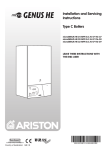
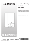
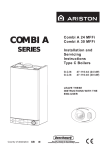
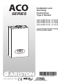
SERIES
Installation and
Servicing
Instructions
Type C Boilers
ACO 27 MFFI G.C.N:
ACO 32 MFFI G.C.N:
ACO 27 RFFI G.C.N:
ACO 32 RFFI G.C.N:
47-116-34
47-116-35
41-116-09
41-116-10
LEAVE THESE INSTRUCTIONS
WITH THE END USER
Country of destination: GB/IE
TABLE OF CONTENTS
1.
GENERAL INFORMATION
TECHNICAL INFORMATION
OVERALL VIEW
PAGE
6.
GENERAL INFORMATION
1.1.
1.2.
1.3.
2.
PAGE
3
4
6
MAINTENANCE
52
6.1.
6.2.
6.3.
6.4.
52
52
52
52
GENERAL REMARKS
CLEANING THE PRIMARY EXCHANGER
CLEANING THE CONDENSATE TRAP
OPERATIONAL TEST
INSTALLATION
2.1.
2.2.
2.3.
2.4.
2.5.
2.6.
2.7.
2.8.
2.9.
2.9.1
2.9.2
2.9.3
2.9.4
2.10.
2.11.
2.11.1.
2.12.
2.13.
2.14.
REFERENCE STANDARDS
SITING THE APPLIANCE
OVERALL DIMENSIONS
MINIMUM CLEARANCES
MOUNTING THE APPLIANCE
ELECTRICAL CONNECTION
GAS CONNECTION
WATER CONNECTIONS
FLUE CONNECTIONS
FITTING THE COAXIAL FLUE
(Ø 60 / 100 HORIZONTAL)
FITTING THE 5” FLUE
(Ø 80 / 125 Horizontal/Vertical)
FITTING THE COAXIAL FLUE
(Ø 60 / 100 VERTICAL)
FITTING THE TWIN PIPE (Ø80 / 80)
FITTING THE MECHANICAL/DIGITAL
TIME CLOCK
SETTING THE MECHANICAL TIME CLOCK
SETTING THE DIGITAL TIME CLOCK
ACCESSORY CONNECTION
ELECTRICAL DIAGRAM
WATER CIRCUIT DIAGRAM
7
7
8
8
9
9
9
10
13
7.
SERVICING INSTRUCTIONS
53
7.1.
7.2.
7.3.
53
53
14
7.3.1.
7.3.2.
7.3.3.
7.3.4.
7.3.5.
7.3.6.
15
7.3.7.
7.4.
7.4.1.
7.4.2.
16
17
7.5.
7.5.1.
20
22
22
24
26
28
7.5.2.
7.5.3.
7.5.4.
7.5.5.
3.
COMMISSIONING
3.1.
3.2.
3.3.
3.4.
3.5.
3.6.
3.6.1.
3.6.2.
3.6.3.
3.6.4.
3.6.5.
3.6.6.
3.7.
3.8.
3.9.
3.10.
3.11.
3.12.
INITIAL PREPARATION
REMOVING THE CASING
CONTROL PANEL
INITIAL START-UP
DISPLAY: MESSAGES SHOWN DURING
NORMAL OPERATION
OPERATING PARAMETERS
REGULATION MENU TABLE
SETTINGS DISPLAY
GAS REGULATION CHECK
IGNITION DELAY ADJUSTMENT
ADJUSTING THE MAXIMUM HEATING
POWER
SOFT LIGHT ADJUSTMENT
CHANGING THE TYPE OF GAS
ADJUSTING THE DOMESTIC HOT
WATER FLOW RATE
BALANCING THE CENTRAL
HEATING SYSTEM
BOILER SAFETY SYSTEMS
COMPLETION
DRAINING
30
32
33
35
7.5.6.
7.5.7.
7.5.8.
7.5.9.
36
37
37
43
44
45
7.5.10.
7.6.1.
7.6.2.
7.6.3.
8.
45
46
47
47
48
5.
SEQUENCE OF OPERATION
51
5.1
5.2
51
51
FAULT FINDING
8.1
54
54
55
55
56
56
58
58
59
59
60
60
60
61
61
62
62
62
63
64
64
65
65
66
66
66
67
68
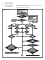
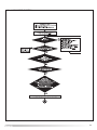
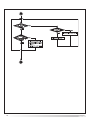
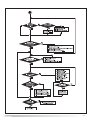
FAULT FINDING GUIDE
(FLOW-CHARTS)
68
9.
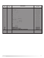
SHORT SPARES PARTS LIST
72
10.
ANNUAL MAINTENANCE CHECKLIST
76
11.
BENCHMARK COMMISSIONING
CHECKLIST
78
SERVICE INTERVAL RECORD
79
45
ZONE VALVES
2
7.6.
45
45
45
4.
CENTRAL HEATING MODE
DOMESTIC HOT WATER MODE
7.5.11.
REPLACEMENT OF PARTS
TO GAIN GENERAL ACCESS
ACCESS TO THE COMBUSTION
CHAMBER
REMOVING THE FAN
REMOVING THE AIR PRESSURE SWITCH
REMOVING THE BURNER
REMOVING THE ELECTRODES
REMOVING THE HEAT EXCHANGER
REMOVING THE CONDENSATE
TRAP (TUBE)
REMOVING THE CONDENSATE TRAP
ACCESS TO THE GAS VALVE
REMOVING THE GAS VALVE
REMOVING THE SPARK GENERATOR
ACCESS TO THE WATER CIRCUIT
REMOVING THE D.H.W.
(SECONDARY) EXCHANGER
REMOVING THE SAFETY VALVE
REMOVING THE AUTOMATIC AIR VENT
REMOVING THE DIVERTER VALVE
ACTUATOR
REMOVING THE DHW FLOW SWITCH
(MFFI ONLY)
REMOVING THE PUMP
REMOVING THE PRESSURE GAUGE
REMOVING THE EXPANSION VESSEL
REMOVING THE D.H.W. TEMPERATURE
PROBE (N.T.C. - MFFI ONLY)
REMOVING THE C.H. FLOW
TEMPERATURE PROBE (N.T.C.)
REMOVING THE C.H. RETURN
TEMPERATURE PROBE (N.T.C.)
ACCESS TO THE CONTROL SYSTEM
CHECKING THE FUSES
REMOVING THE PRINTED CIRCUIT
BOARDS
REMOVING THE TIME CLOCK
12.
1. GENERAL INFORMATION
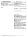
1.1.
This manual is an integral and essential part of the product. It
should be kept with the appliance so that it can be consulted by
the user and our authorised personnel.
Read the instructions and recommendations in these Installation
and Servicing Instructions carefully to ensure proper installation,
use and maintenance of the appliance.
Please carefully read the instructions and notices about the unit
contained in this manual, as they provide important information
regarding the safe installation, use and maintenance of the
product.
Keep this manual in a safe place. You may need it for your own
reference while Servicing Technicians or your installer may
need to consult it in the future.
For operating instructions please consult the separate Users
Manual.
GENERAL INFORMATION
The ACO MFFI range is a combined appliance for the
production of central heating (C.H.) and domestic hot water
(D.H.W.).
The ACO RFFI range is an appliance for the production of
Central Heating (C.H.) and is designed for use with an indirect
cylinder for Domestic Hot Water (D.H.W.)
The ACO MFFI and RFFI range of boilers are domestic gas
boilers and intended for domestic use only.
This appliance must be used only for the purpose for which it is
designed.
The manufacturer declines all liability for damage caused by
improper or negligent use.
No asbestos or other hazardous materials have been used in
the fabrication of this product.
MTS recommends the use of protective clothing when installing
and working on the appliance i.e. gloves.
Before connecting the appliance, check that the information
shown on the data plate and the table in Section 1.2 (page 4)
comply with the electric, water and gas mains of the property.
You will find the data plate on the reverse of the control panel.
The gas with which this appliance operates is also shown on the
label at the bottom of the boiler.
Do not install this appliance in a damp environment or close to
equipment which spray water or other liquids.
Do not place objects on the appliance.
Do not allow children or inexperienced persons to use the
appliance without supervision.
If you smell gas in the room, do not turn on or off light
switches, use the telephone or any other object which might
cause sparks.
Open doors and windows immediately to ventilate the room.
Shut the gas mains tap (at or adjacent to the gas meter) or the
valve of the gas cylinder and call your Gas Supplier immediately.
Always disconnect the appliance either by unplugging it from
the mains or turning off the mains switch before cleaning the
appliance or carrying out maintenance.
In the case of faults or failure, switch off the appliance and
turn off the gas tap. Do not tamper with the appliance.
For repairs, call your local Authorised Servicing Agent and
request the use of original spare parts. For in-guarantee repairs
contact MTS (GB) Limited.
3
General Info
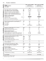
Name
CE Certification
Flue Type
Energy Performance
Heat Input max (Domestic Hot Water)
Heat Input max/min (Central Heating)
Heat Output max (Domestic Hot Water)
Heat Output max/min (Central Heating)
Efficiency of Nominal Heat Input (60/80°C)
Efficiency of Nominal Heat Input (30/50°C)
Efficiency at 30% of Nominal Heat Input (47°C)
Efficiency at 30% of Nominal Heat Input (30°C)
Efficiency at Minimum Input
Efficiency (Dir. 92/42/EEC)**
SEDBUK Rating
Heat Loss to the Casing (DT=50°C)
Flue Heat Loss with Burner Operating
Emissions
Max Discharge of Products of Combustion (G20)
Temp. of exhaust fumes at nominal capacity
CO2 Content
O2 Content
CO Content
Nox Class
Kg/h
°C
%
%
ppm
35.3
72
9.1
4.3
109
5 (70 mg/kW/h)
35.3
72
9.1
4.3
109
5 (70 mg/kW/h)
Central Heating
TECHNICAL INFORMATION
Head Loss on Water Side (max) (DT=20°C)
Residual Head of System
Expansion Vessel Pre-load Pressure
Maximum Heating Pressure
Expansion Vessel Capacity
Maximum Water Content of System
Heating Temperature max/min (High temperature)
Heating Temperature max/min (Low Temperature)
mbar
bar
bar
bar
l
l
°C
°C
200
0.2
0.7
3
7
130
82 / 46
75 / 20
200
0.2
0.7
3
7
130
82 / 46
75 / 20
Domestic Hot Water
1.2.
Domestic Hot Water Temperature (approx) max/min
Specific Flow Rate (10 minutes/DT 30°C)
D.H.W. Flow Rate DT=25°C
D.H.W. Flow Rate DT=35°C
D.H.W. Minimum Flow Rate
Pressure of Domestic Hot Water max/min
°C
l/min
l/min
l/min
l/min
bar
56 / 36
12.6
15.2
10.8
2.5
6 / 0.2
Max. Condensate produced
PH of condensate
l/h
W
kW
kW
kW
kW
%
%
%
%
%
30.0
25.5 / 8.9
27.0
22.5 / 7.7
88.2
91.8
92.9
96.8
86.7
----------25.5 / 8.9
----------22.5 / 7.7
88.2
91.8
92.9
96.8
86.7
A / 90.4
0.5
2.6
A / 90.5
0.5
2.6
1.5
4
1.5
4
Gas
ACO 27 RFFI (SYSTEM)
0085BP0229
C13-C33-C43-C53-C83-B23-B33
Nominal Pressure Natural Gas (G20)
Consumption at Nominal Capacity(G20)
Gas Consumption after 10 Minutes*
mbar
m3/h
m3
20
2.43
0.85
20
2.43
0.85
Electrical Data
Band / %
%
%
ACO 27 MFFI (COMBI)
0085BP0229
C13-C33-C43-C53-C83-B23-B33
Electrical Supply
Power Consumption
Minimum Ambient Temperature
Protection Grade of Electrical System
Internal Fuse Rating
V/Hz
W
°C
IP
230/50
118
+5
24D
2A Fast Fuse
230/50
118
+5
24D
2A Fast Fuse
Weight
Casing Dimensions (D/W/H)
Kg
mm
41
280/450/750
40
280/450/750
47-116-34
41-116-09
G.C. Number
* Calculated at 70% maximum output
** Calculated on Upper calorific value
4
General Info
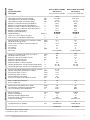
Name
CE Certification
Flue Type
Energy Performance
Heat Input max (Domestic Hot Water)
Heat Input max/min (Central Heating)
Heat Output max (Domestic Hot Water)
Heat Output max/min (Central Heating)
Efficiency of Nominal Heat Input (60/80°C)
Efficiency of Nominal Heat Input (30/50°C)
Efficiency at 30% of Nominal Heat Input (47°C)
Efficiency at 30% of Nominal Heat Input (30°C)
Efficiency at Minimum Input
Efficiency (Dir. 92/42/EEC)**
SEDBUK Rating
Heat Loss to the Casing (DT=50°C)
Flue Heat Loss with Burner Operating
Emissions
Max Discharge of Products of Combustion (G20)
Residual Discharge Head
Temp. of exhaust fumes at nominal capacity
CO2 Content
O2 Content
CO Content
Nox Class
Kg/h
mbar
°C
%
%
ppm
45.7
1
76.4
8.7
5
71
5 (70 mg/kW/h)
45.7
1
76.4
8.7
5
71
5 (70 mg/kW/h)
Central Heating
Head Loss on Water Side (max) (DT=20°C)
Residual Head of System
Expansion Vessel Pre-load Pressure
Maximum Heating Pressure
Expansion Vessel Capacity
Maximum Water Content of System
Heating Temperature max/min (High temperature)
Heating Temperature max/min (Low Temperature)
mbar
bar
bar
bar
l
l
°C
°C
200
0.2
0.7
3
7
130
82 / 46
75 / 20
200
0.2
0.7
3
7
130
82 / 46
75 / 20
Domestic Hot Water
Domestic Hot Water Temperature (approx) max/min
Specific Flow Rate (10 minutes/DT 30°C)
D.H.W. Flow Rate DT=25°C
D.H.W. Flow Rate DT=35°C
D.H.W. Minimum Flow Rate
Pressure of Domestic Hot Water max/min
°C
l/min
l/min
l/min
l/min
bar
56 / 36
15.3
18.3
13.1
2.5
6 / 0.2
Max. Condensate produced
PH of condensate
l/h
W
kW
kW
kW
kW
%
%
%
%
%
32.0
31.6 /10.5
32.0
28 / 9.5
88.5
88.7
91.2
97.1
89.7
----------31.6 /10.5
----------28 / 9.5
88.5
88.7
91.2
97.1
89.7
A / 90.4
1
2.7
A / 90.5
1
2.7
1.8
4
1.8
4
Gas
ACO 32 RFFI (SYSTEM)
0085BP0229
C13-C33-C43-C53-C83-B23-B33
Nominal Pressure Natural Gas (G20)
Consumption at Nominal Capacity(G20)
Gas Consumption after 10 Minutes*
mbar
m3/h
m3
20
3.01
0.35
20
3.01
0.35
Electrical Data
Band / %
%
%
ACO 32 MFFI (COMBI)
0085BP0229
C13-C33-C43-C53-C83-B23-B33
Electrical Supply
Power Consumption
Minimum Ambient Temperature
Protection Grade of Electrical System
Internal Fuse Rating
V/Hz
W
°C
IP
230/50
118
+5
24D
2A Fast Fuse
230/50
118
+5
24D
2A Fast Fuse
Weight
Casing Dimensions (D/W/H)
Kg
mm
42
280/450/750
41
280/450/750
47-116-35
41-116-10
G.C. Number
* Calculated at 70% maximum output
** Calculated on Upper calorific value
5
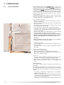
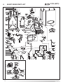
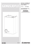
1.3.
OVERALL VIEW
27/32 RFFI (SYSTEM)
27/32 MFFI (COMBI)
1
26
1
26
2
3
25
2
3
25
4
5
4
5
6
7
8
6
7
8
24
24
9
9
23
23
22
22
21
20
10
20
11
19
19
18
18
12 13 14 15
16 17
10
12
14 15
16 17
FIG. 1.0
LEGEND:
1. Flue connector
2. Mixer
3. Fan
4. Spark generator
5. Burner
6. Ignition and detection electrode
7. Air release valve
8. Main heat exchanger (aluminium)
9. Central Heating flow temperature probe
10. Automatic by-pass
11. Domestic Hot Water temperature probe
12. Safety valve (3 bar)
13. Secondary heat exchanger
14. Gas valve
15. Condensate discharge
16. Condensate trap inspection cap
17. Drain valve
18. Domestic Hot Water flow switch
19. Circulation pump with automatic air release valve
20. Condensate trap
21. Diverter valve
22. Condensate trap (tube)
23. Central Heating return temperature probe
24. Expansion vessel
25. Air pressure switch
26. Combustion analysis test point
6
2. INSTALLATION
2.1.
REFERENCE STANDARDS
The technical information and instructions provided herein below
are intended for the installer / Servicing Technician so that the
unit may be installed and serviced correctly and safely.
In the United Kingdom the installation and initial start up of the
boiler must be by a CORGI Registered Installer in accordance
with the installation standards currently in effect, as well as with
any and all local health and safety standards i.e. CORGI.
In the Republic of Ireland the installation and initial start up of
the appliance must be carried out by a Competent Person in
accordance with the current edition of I.S.813 “Domestic Gas
Installations”, the current Building Regulations, reference should
also be made to the current ETCI rules for electrical installation.
This appliance must be installed by a competent installer in
accordance with current Gas Safety (installation & use)
Regulations.
The installation of this appliance must be in accordance with the
relevant requirements of the Local Building Regulations, the
current I.E.E. Wiring Regulations, the bylaws of the local water
authority, in Scotland, in accordance with the Building Standards
(Scotland) Regulation and Health and Safety document No. 635
“Electricity at work regulations 1989” and in the Republic of
Ireland with the current edition of I.S. 813, the Local Building
Regulations (IE).
C.O.S.H.H.
Materials used in the manufacture of this appliance are nonhazardous and no special precautions are required when
servicing.
2.2.
SITING THE APPLIANCE
The appliance may be installed in any room or indoor area,
although particular attention is drawn to the requirements of the
current I.E.E. Wiring Regulations, and in Scotland, the electrical
provisions of the Building Regulations applicable in Scotland,
with respect to the installation of the combined appliance in a
room containing a bath or shower, the location of the boiler in a
room containing a bath or shower should only be considered if
there is no alternative.
Where a room-sealed appliance is installed in a room
containing a bath or shower the appliance and any
electrical switch or appliance control, utilising mains
electricity should be situated so that it cannot be touched
by a person using the bath or shower, specifically in
accordance with current IEE Wiring Regulations.
The location must permit adequate space for servicing and air
circulation around the appliance as indicated in Section 2.4.
The location must permit the provision of an adequate flue and
termination.
For unusual locations special procedures may be necessary.
BS 6798-2000 gives detailed guidance on this aspect.
A compartment used to enclose the appliance must be designed
specifically for this purpose. No specific ventilation requirements
are needed for the installation within a cupboard.
This appliance is not suitable for outdoor installation.
The type C appliances (in which the combustion circuit, air
vent intake and combustion chamber are air-tight with
respect to the room in which the appliance is installed) can
be installed in any type of room.
Secondary ventilation is not required with this boiler. The boiler
must be installed on a solid, non-combustible, permanent wall to
prevent access from the rear.
Installation should also comply with the following British
Standard Codes of Practice:
Treatment of water in domestic hot water
central heating systems
BS 5546:1990 Installation of hot water supplies for
domestic purposes
BS 5440-1:2000 Flues
BS 5440-2:2000 Air supply
BS 5449:1990 Forced circulation hot water systems
BS 6798:2000 Installation of gas fired hot water boilers
of rated input not exceeding 70kW
BS 6891:1989 Installation of low pressure gas pipe up to
28mm
BS 7671:2001 IEE wiring regulations
BS 4814:1990 Specification for expansion vessels
BS 5482:1994 Installation of L.P.G.
BS 7593:1992
and in the Republic of Ireland in accordance with the following
Codes of Practice:
I.S. 813
Domestic Gas Installations
7
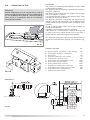
2.3.
OVERALL DIMENSIONS
27/32 RFFI (SYSTEM)
785
FIG. 2.1
280
450
FIG. 2.0
2.4.
LEGEND:
A = Central Heating Flow (3/4”) (22mm Copper Tail)
B = Domestic Hot Water Outlet (1/2”) (15 mm Copper Tail)
C = Gas Inlet (3/4”) ( 22mm Copper Tail)
D = Domestic Cold Water Inlet (1/2”) (15mm Copper Tail)
E = Central Heating Return (3/4”) (22mm Copper Tail)
F = Condensate discharge
SV outlet = 1/2” Female BSP (Not Shown)
MINIMUM CLEARANCES
In order to allow access to the interior of the boiler for maintenance
purposes, the boiler must be installed in compliance with the
clearance requirements indicated in the diagram below.
27/32 MFFI/RFFI
27/32 MFFI (COMBI)
FIG. 2.3
FIG. 2.2
8
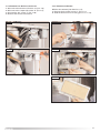
2.5. MOUNTING THE APPLIANCE
After removing the boiler from its packaging, remove the
template from the separate box containing the connection kit.
NOTE: Pay particular attention to any test water that may spill
from the appliance.
Place the template in the position the appliance is to be
mounted and after ensuring it is hanging squarely, use it to mark
the holes for the hanging bracket, connection kit and flue pipe(s)
NB: For further information relating to the flue installation please
refer to Section 2.9 FLUE CONNECTION. (If the appliance is to be
fitted on a wall of combustible material, the wall must be
protected by a sheet of fireproof material).
If the appliance is to be fitted into a timber framed building,
guidance should be sought from the Institute of Gas Engineers
document REF: IGE/UP/7.
2.5.1. Drill the wall and plug using those supplied with the
connections kit, position the hanging bracket and secure with the
wall screws supplied, assemble the connection kit and secure to
the wall. NOTE: It is highly recommended that a spirit level be
used to position the appliance to ensure that it is perfectly level.
2.5.2. Position the appliance on the hanging bracket and
connect the connection kit to the boiler connections. (see also
Sections 2.7 Gas Connections, 2.8 Water Connections & FIG.
2.5).
For safety purposes, have a competent person carefully check
the electrical system in the property, as the manufacturer will not
be held liable for damage caused by the failure to earth the
appliance properly or by anomalies in the supply of power. Make
sure that the residential electrical system is adequate for the
maximum power absorbed by the unit, which is indicated on the
rating plate. In addition, check that the section of cabling is
appropriate for the power absorbed by the boiler.
Note: The diagrams for the electrical system are indicated in
Sections 2.12 and 2.13.
Warning, this appliance must be earthed.
External wiring to the appliance must be carried out by a
competent person and be in accordance with the current I.E.E.
Regulations and applicable local regulations.
The appliance is supplied with a fly-lead already connected, this
must be connected to a 240v supply fused at 3A and must
facilitate complete electrical isolation of the appliance, by the
use of a fused double pole isolator having a contact separation
of at least 3 mm in all poles or alternatively, by means of a 3 A
fused three pin plug and unswitched shuttered socket outlet
both complying with BS 1363.
The point of connection to the Electricity supply must be readily
accessible and adjacent to the appliance unless the appliance is
installed in a bathroom when this must be sited outside the
bathroom (see Section 2.2).
Should external controls be required, the design of the external
electrical circuits should be undertaken by a competent person,
see Sections 2.12 and 4 for further information.
2.7.
GAS CONNECTION
The local gas region contractor connects the gas meter to the
service pipe.
If the gas supply for the boiler serves other appliances ensure
that an adequate supply is available both to the boiler and the
other appliances when they are in use at the same time.
Pipe work must be of an adequate size. Pipes of a smaller size
than the boiler inlet connection must not be used.
2.6. ELECTRICAL CONNECTION
The boiler operates with alternating current, as indicated in the
technical data table (Section 1.2), where the maximum absorbed
power is also indicated. Make sure that the connections for the
neutral and live wires correspond to the indications in the
diagram. The appliance electrical connections are situated inside
the electrical box (see Section 2.12).
IMPORTANT!
In the event that the power supply cable must be changed,
replace it with one with the same specifications. Make the
connections to the terminal board located within the control
panel, as follows:
- The yellow-green wire should be connected to the terminal
marked with the earth symbol; make sure to re-use the ferrule
mounted on the other supply cable;
- The blue wire should be connected to the terminal marked
“N”;
- The brown wire should be connected to the terminal marked
“L”.
85 mm
220 mm
FIG. 2.4
9
2.8.
WATER CONNECTIONS
VIEW OF THE BOILER CONNECTIONS
Legend:
27/32 MFFI (COMBI)
A
B
C
D
E
H
I
J
I
B
A
C
D
J
E
H
27/32 RFFI (SYSTEM)
I
C
A
J
E
H
FIG. 2.5
RESIDUAL HEAD OF THE BOILER ∆T20°C
(mbar)
500
400
300
200
=
=
=
=
=
=
=
=
Central Heating Flow
Domestic Hot Water Outlet
Gas Inlet
Domestic Cold Water Inlet
Central Heating Return
Condensate discharge
Safety valve discharge
Drain valve
Central Heating
Detailed recommendations are given in BS 6798:2000 and BS
5449-1:1990, the following notes are given for general guidance.
PIPE WORK:
Copper tubing to BS EN 1057:1996 is recommended for
water pipes. Jointing should be either with capillary soldered
or compression fittings.
Where possible pipes should have a gradient to ensure air is
carried naturally to air release points and water flows
naturally to drain taps.
The appliance has a built-in automatic air release valve, however
it should be ensured as far as possible that the appliance heat
exchanger is not a natural collecting point for air.
Except where providing useful heat, pipes should be
insulated to prevent heat loss and avoid freezing.
Particular attention should be paid to pipes passing through
ventilated spaces in roofs and under floors.
BY-PASS:
The appliance includes an automatic by-pass valve, which
protects the main heat exchanger in case of reduced or
interrupted water circulation through the heating system, due
to the closing of thermostatic valves or cock-type valves
within the system.
SYSTEM DESIGN:
This boiler is suitable only for sealed systems.
DRAIN COCKS:
These must be located in accessible positions to permit the
draining of the whole system. The taps must be at least
15mm nominal size and manufactured in accordance with BS
2870:1980.
SAFETY VALVE DISCHARGE:
The discharge should terminate facing downwards on the
exterior of the building in a position where discharging
(possibly boiling water & steam) will not create danger or
nuisance, but in an easily visible position, and not cause
damage to electrical components and wiring.
The discharge must not be over an entrance or a window or
any other type of public access.
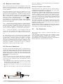
CONDENSATE DISCHARGE:
A flexible hose is supplied for connection to the condensate
discharge point H (Fig. 2.5). The condensate discharge hose
from the boiler must have a continuous fall of 2.5° and must
be inserted by at least 50 mm into a suitable acid resistant
pipe - e.g. plastic waste or overflow pipe. The condensate
discharge pipe must have a continuous fall and preferably be
installed and terminated within the building to prevent
freezing.
100
N OT E : T H E
FLEXIBLE CONDENSE HOSE SUPPLIED WITH THE
APPLIANCE CAN BE EXTENDED BY PULLING THE TUBE OPENING THE
0
RIBBED PIPE.
0
FIG. 2.6
10
200
400
600
800
1000
1200 (l/h)
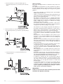
The discharge pipe must be terminated in a suitable position:
i) Connecting in to an internal soil stack (at least 450 mm
above the invert of the stack). A trap giving a water seal of
at least 75 mm must be incorporated into the pipe run,
there also must be an air break upstream of the trap.
ii) Connecting into the waste system of the building such as
a washing machine or sink trap. The connection must be
upstream of the washing machine/sink (If the connection
is down stream of the waste trap then an additional trap
giving a minimum water seal of 75 mm and an air break
must be incorporated in the pipe run, as above.
iii) Terminating into a gully, below the grid level but above the
water level.
iv) Into a soakway.
NOTE: If any condensate pipe work is to be installed externally,
then it should be kept to a minimum and be insulated with a
waterproof insulation and have a continuous fall.
Some examples of the type of condensate drains can be
found on pages 11 and 12.
AIR RELEASE POINTS:
These must be fitted at all high points where air naturally
collects and must be sited to facilitate complete filling of the
system.
The appliance has an integral sealed expansion vessel to
accommodate the increase of water value when the system is
heated.
It can accept up to 7 l (1.5 gal) of expansion water. If the
heating circuit has an unusually high water content, calculate
the total expansion and add an additional sealed expansion
vessel with adequate capacity.
MAINS WATER FEED - CENTRAL HEATING:
There must be no direct connection to the mains water supply
even through a non-return valve, without the approval of the
Local Water Authority.
FILLING:
A method for initially filling the heating system is supplied with
the connection kit. The filling loop is connected between the
cold water inlet and the central heating flow connections, and
incorporates a non-return valve. To operate the filling loop, it
is necessary to open both quarter turn handles, once the
required pressure has been achieved, close both handles and
disconnect the hose in accordance with water byelaws and
cap off with the cap supplied. N OTE: The installer should
ensure that there are no leaks as frequent filling of the
heating system can lead to premature scaling of the main
exchanger and failure of hydraulic components.
DOMESTIC WATER
The domestic water must be in accordance with the relevant
recommendation of BS 5546:1990. Copper tubing to BS EN
1057:1996 is recommended for water carrying pipe work and
must be used for pipe work carrying drinking water, a scale
reducer should also be used to reduce the risk of scale
forming in the domestic side of the heat exchanger.
UNDER FLOOR HEATING SYSTEMS:
In the event of an under floor heating system, fit a safety
thermostat on the boiler flow (see Section 2.12). This
thermostat should be positioned at a safe distance from the
boiler to ensure the correct operation of the same. If the
thermostat is positioned too close to the boiler, the water
remaining in the boiler after domestic hot water has been
drawn will flow into the central heating system and may cause
the thermostat contact to open without there being any real
danger of the system being damaged, this would lead to a
boiler shutdown both in D.H.W. mode and C.H. mode, and the
error code “E08” would be displayed; boiler operation resumes
automatically when the thermostat contact closes on cooling.
Should the thermostat fail to be installed as recommended, the
under floor heating system can be protected by installing a
thermostatic valve upstream from the thermostat in order to
prevent the flow of excessively hot water towards the system.
27/32 RFFI (SYSTEM)
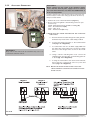
1. Internal termination of condensate drainage pipe to
internal stack
27/32 MFFI (COMBI)
11
2. External termination of condensate drainage pipe via
internal discharge branch (e.g. sink waste) and condensate
siphon
WATER TREATMENT
The boiler is equipped with an aluminium alloy main heat
exchanger.
The detailed recommendations for water treatment are given in
BS 7593:1992 (Treatment of water in domestic hot water central
heating systems); the following notes are given for general
guidance;
- If the boiler is installed on an existing system, any unsuitable
additives must be removed;
- Under no circumstances should the boiler be fired before the
system has been thoroughly flushed; the flushing procedure
must be in line with BS7593:1992.
We highly recommend the use of a flushing detergent
appropriate for the metals used in the aluminium alloy circuit.
These include (Fernox Superfloc, BetzDearborn Sentinel
X300 or X400), whose function is to dissolve any foreign
matter that may be in the system;
In hard water areas or where large quantities of water are in
the system the treatment of the water to prevent premature
scaling of the main heat exchanger is necessary.
3. External termination of condensate drainage pipe via
internal discharge branch (e.g. sink waste - proprietary fitting).
4. External termination of condensate drainage pipe via
condensate siphon
The formation of scale strongly compromises the efficiency of
the thermic exchange because small areas of scale cause a
high increase of the temperature of the metallic walls and
therefore add to the thermal stress of the heat exchanger.
Demineralised water is more aggressive so in this situation it
is necessary to treat the water with an appropriate corrosion
inhibitor.
- Any treatment of water by additives in the system for frost
protection or for corrosion inhibition has to be absolutely
suitable for all the metals used in the circuit including the
aluminium alloys.
The use of a corrosion inhibitor in the system such as Fernox
MB-1Copal, BetzDeaborn Sentinel X100 System Inhibitor is
recommended to prevent corrosion (sludge) damaging the
boiler and system;
- If anti-freeze substances are to be used in the system, check
carefully that they are compatible with the aluminium.
In particular, DO NOT USE ordinary ETHYLENE GLYCOL,
since it is corrosive in relation to aluminium and its alloy, as
well being toxic.
MTS suggests the use of suitable anti-freeze products such
as Fernox ALPHI 11, which will prevent rust and incrustation
taking place.
Periodically check the pH of the water/anti-freeze mixture of
the boiler circuit and replace it when the amount measured is
out of the range stipulated by the manufacturer ( 7 < pH < 8).
DO NOT MIX DIFFERENT TYPES OF ANTI-FREEZE
- In under-floor systems, the use of plastic pipes without
protection against penetration of oxygen through the walls
can cause corrosion of the system’s metal parts (metal
piping, boiler, etc), through the formation of oxides and
bacterial agents.
To prevent this problem, it is necessary to use pipes with an
“oxygen-proof barrier”, in accordance with standards DIN
4726/4729. If pipes of this kind are not used, keep the
system separate by installing heat exchangers of those
with a specific system water treatment.
IMPORTANT
Failure to carry out the water treatment procedure will
invalidate the appliance warranty.
12
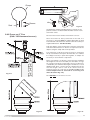
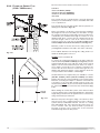
2.9.
CONNECTING THE FLUE
IMPORTANT!!
BEFORE CONNECTING THE FLUE, ENSURE THAT
1
LITRE OF
WATER HAS BEEN POURED INTO THE EXHAUST CONNECTION TO
FILL THE CONDENSATE TRAP
(FIG.2.7).
SHOULD THE TRAP BE
EMPTY THERE IS A TEMPORARY RISK OF FLUE GASSES
ESCAPING INTO THE ROOM.
FLUE SYSTEM
The provision for satisfactory flue termination must be made
as described in BS 5440-1.
The appliance must be installed so that the flue terminal is
exposed to outdoor air.
The terminal must not discharge into another room or space
such as an outhouse or lean-to.
It is important that the position of the terminal allows a free
passage of air across it at all times.
The terminal should be located with due regard for the
damage or discolouration that might occur on buildings in the
vicinity, it must also be located in a place not likely to cause
nuisance.
In cold or humid weather water vapour may condense on
leaving the flue terminal.
The effect of such “steaming” must be considered.
If the terminal is 2.1 metres above a balcony, above ground
or above a flat roof to which people have access, then a
suitable stainless steel terminal guard must be fitted.
The minimum acceptable spacing from the terminal to
obstructions and ventilation openings are specified in Fig.
2.9.
FIG. 2.7
TERMINAL POSITION
E
E
FIG. 2.9
ABCDEF GHI J KL -
Directly below an open window or other opening
Below gutters, solid pipes or drain pipes
Below eaves
From vertical drain pipes and soil pipes
From internal or external corners
Above ground on a public walkway or patio
From a surface facing a terminal
From a terminal facing a terminal
Vertically from a terminal in the same wall
Horizontally from a terminal in the same wall
Horizontally from an opening window
Fixed by vertical flue terminal
mm
300
75
200
75
300
2100
2500
2500
1500
300
300
Ø 60/100 mm
4
Fig. 2.9
13
Warning
The exhaust gas ducts must not be in contact with or close to
inflammable material and must not pass through building
structures or walls made of inflammable material.
When replacing an old appliance, the flue system must be
changed.
Important
Ensure that the flue is not blocked.
Ensure that the flue is supported and
assembled in accordance with these
instructions.
Level
118
Installation without extension
Fig. 2.10
Level
Installation with extension
Fig. 2.11
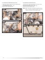
2.9.1 FITTING THE COAXIAL FLUE
(Ø 60 / 100 HORIZONTAL)
CONTENTS:
1X SILICONE O-RING (60mm)
1X ELBOW (90 )
2X WALL SEALS (INTERNAL & EXTERNAL)
1X FLUE PIPE INCLUDING TERMINAL (1 METRE - 60/100)
1X FLUE CLAMP
1X SCREWS
1x Seal
Once the boiler has been positioned on the wall, insert the
elbow into the socket and rotate to the required position. NOTE:
It is possible to rotate the elbow 360o on its vertical axis.
O
Using the flue clamp, seals and screws supplied (Fig 2.12)
secure the elbow to the boiler.
The 1 metre horizontal flue kit (3318073) supplied is suitable
for an exact X dimension of 815mm.
Measure the distance from the face of the external wall to the
face of the flue elbow (X - Fig 2.9), this figure must now be
subtracted from 815mm, you now have the total amount to be
cut from the plain end of the flue.
Draw a circle around the outer flue and cut the flue to the
required length taking care not to cut the inner flue, next cut
the inner flue ensuring that the length between the inner and
outer flue is maintained. (Fig 2.12).
e.g.
X = 555mm
815-555 = 260mm (Length to be cut from the plain end of
the flue).
Once cut to the required length, ensure that the flue is free
from burrs and reassemble the flue. If fitting the flue from
inside of the building attach the grey outer wall seal to the flue
terminal and push the flue through the hole, once the wall
seal has passed through the hole, pull the flue back until the
seal is flush with the wall. Alternatively, the flue can be
installed from outside of the building, the grey outer seal
being fitted last.
14
Clamp
Screws
Seal
Fig. 2.12
Should the flue require extending, the flue connections are
push fit, however, one flue bracket should be used to secure
each metre of flue.
2.9.2 FITTING THE 5” FLUE
(Ø 80 / 125 HORIZONTAL/VERTICAL)
NOTE: SEE PAGE 19 FOR MAXIMUM AND MINIMUM FLUE RUNS.
Once the boiler has been positioned on the wall, it is
necessary to insert the Ø80/125 adaptor (FIG. 2.13) for both
horizontal and vertical flue runs into the boiler flue socket (not
supplied with flue kit - Part No 3318095).
Push the adaptor onto the boilers flue connection, grease the
seals then add extensions or elbows as required, secure the
adaptor, using the clamp and screws provided.
To fit extensions or elbows it is first necessary to ensure that
the lip seal is fitted correctly into the inner flue, once verified,
it is simply necessary to push them together, no clamps are
necessary to secure the flue components.
Before proceeding to fit the flue, ensure that the maximum
flue length has not been exceeded (See the tables on Page
19) and that all elbows and bends have been taken into
consideration, the maximum flue length is 10 metres, for each
additional 90o elbow 1 metre must be subtracted from the
total flue length, and for each 45 o 0.5 metres must be
subtracted from the total flue length (the height of the
vertical adaptor and a 45o bend can be seen in Fig. 2.14
and a 90o bend in Fig. 2.15).
Fig. 2.13
NOTE: DO NOT CUT THE VERTICAL FLUE KIT.
Fig. 2.14
Fig. 2.15
15
NOTE: SEE PAGE 19 FOR MAXIMUM AND MINIMUM FLUE RUNS.
2.9.3. FITTING THE COAXIAL FLUE
(Ø 60 / 100 VERTICAL)
CONTENTS:
1X SILICONE O-RING (60mm)
1X CONICAL ADAPTOR (60/100mm)
1X VERTICAL FLUE KIT (80/125mm)
3X SCREWS
The vertical flue kit is supplied with a specially designed
weather proof terminal fitted, it can be used either with a flat
roof or a pitched roof.
The Vertical flue kits useable lengths with the pitched roof
flashings are indicated in Fig. 2.16.
Before proceeding to fit the flue, ensure that the maximum
flue length has not been exceeded (See the tables on Page
19) and that all elbows and bends have been taken into
consideration, the maximum flue length is 4 metres, for each
additional 90o elbow 1 metre must be subtracted from the
total flue length, and for each 45 o 0.5 metres must be
subtracted from the total flue length (the height of the
vertical adaptor and a 45o bend can be seen in Fig. 2.17).
Mark the position of the flue hole in the ceiling and/or roof
(see Fig. 2.15 for distance from wall to the centre of the flue).
Cut a 120mm diameter hole through the ceiling and/or roof
and fit the flashing plate to the roof.
Fig. 2.16
DO NOT cut the vertical flue kit.
To connect the vertical flue kit directly to the boiler, place the
vertical starter kit (Part No. 3318079) (see Fig. 2.16) onto the
exhaust manifold and secure with the clamp, fit the vertical
adaptor onto the vertical starter kit (note: there is no need to
use a clamp to secure this as it is a push fit connection), the
vertical flue kit must then be inserted through the roof
flashing, this will ensure that the correct clearance above the
roof is provided as the terminal is a fixed height.
Should extensions be required, they are available in 1 metre
(Part No. 3318077), 500mm (Part No. 3318078) and 160mm
lengths, they must be connected directly to the vertical starter
kit before connecting the adaptor to allow the vertical flue kit
to be fitted. In the event that extension pieces need to be
shortened, they must only be cut at the male end and it must
be ensured that the inner and outer flue remain flush (Fig.
2.12)
When utilising the vertical flue system, action must be taken
to ensure that the flue is supported adequately to prevent the
weight being transferred to the appliance flue connection by
using 1 flue bracket per extension.
Fig. 2.17
16
When the flue passes through a ceiling or wooden floor, there
must be an air gap of 25mm between any part of the flue
system and any combustible material. The use of a ceiling
plate will facilitate this. Also when the flue passes from one
room to another a fire stop must be fitted to prevent the
passage of smoke or fire, irrespective of the structural
material through which the flue passes.
2.9.4. FITTING THE TWIN PIPE (Ø80 / 80)
NOTE: SEE PAGE 19 FOR MAXIMUM AND MINIMUM FLUE RUNS.
Where it is not possible to terminate the flue within the
distance permitted for coaxial flues, the twin flue pipe can be
used by fitting a special adaptor to the flue connector and
using the aperture for the air intake located on top of the
combustion chamber.
Always ensure that the flue is adequately supported, using
one flue bracket per extension and avoiding low points. (MTS
supply suitable clamps as Part No. 705778).
To utilise the air intake it is necessary to:
1) Take the air intake cover off the top of the appliance
2) Assemble the flange on the header supplied with the boiler
3) Insert the header on the tube or the elbow up until the
lower stop (you do not have to use the washer).
4) Insert the elbow/header in the boiler air intake hole and
fasten it with screws.
The twin flue pipes can be fitted with or without additional
elbows and need no clamps, simply ensure that the red o-ring
is inserted in the female end of the flue pipe and push the
extension piece fully into the previous section of flue pipe or
elbow, check that the o-ring is not dislodged when
assembling the flue (greasing the seal will aid assembly).
Twin pipe can also be converted back to Coaxial flue to
enable vertical termination with a coaxial kit by using the pipe
bridge (Twin - Coaxial Adaptor - Part No. 3318089). When
running the twin flue pipe vertically.
It is not possible to terminate concentrically horizontally.
Termination is only possible with separate air and exhaust
terminals.
When siting the twin flue pipe, the air intake and exhaust
terminals must terminate on the same wall, the centres of the
terminals must be a minimum of 280 mm apart and the air
intake must not be sited above the exhaust terminal (refer to
Fig. 2.20). The air intake pipe can be run horizontally,
however, the terminal and the final 1 metre of flue must be
installed either horizontally or with a slight fall away from the
boiler to avoid rain ingress.
It is also strongly recommended that the air intake pipe run be
constructed of insulated pipe to prevent condense forming on
the outside of the tube.
The maximum per missible flue length for twin flue is
dependent on the type of run used.
For flue runs with the intake and exhaust pipes under the
same atmospheric conditions (TYPE 4) the maximum length is
38 metres (27kW) and 48 metres (32kW), for runs with the
terminals under different atmospheric conditions (TYPE 5) the
exhaust terminal must extend 0.5 metres above the ridge of
the roof (this is not obligatory if the exhaust and air intake
pipes are located on the same side of the building). For TYPE
5 also, the maximum permissible combined length is 51
metres (27kW) and 49 metres (32kW).
The maximum length is reached by combining the total
lengths of both the air intake and exhaust pipes. Therefore a
maximum length of 40 metres for example, will allow a flue
and 20 metres for the
run of 20 metres for the air intake
o
exhaust pipes, also for each 90 elbow 2.2 metres must be
subtracted from the total length and for each 45o elbow 1.4
metres must be subtracted from the total flue length.
Some of the acceptable flue configurations are detailed on
page 20.
For further information relating to flue runs not illustrated,
please contact the Technical Department on 0870 241 8180.
17
Fig. 2.18
ø 100
In the event that the air intake and exhaust are run to the
left, it will be necessary to reduce the height of the air
intake by cutting 20mm from the base of the air intake
elbow (see Fig. 2.18)
In the event that twin flue pipes are used, and the boiler
has a side clearance of less than 60mm from the wall, it
is necessary to cut a larger diameter hole for the flue
pipe, this should be ø10 cm, this will then allow for easier
assembly of the air intake elbow and the tube outside the
wall (see Fig. 2.19).
60 mm
Fig. 2.19
Fig. 2.20
18
For coaxial systems, the maximum development
value, mentioned in the table below also takes into
account an elbow.
For twin flue systems the maximum development
value, mentioned in the table includes the exhaust
gas/air intake terminal.
Type 5 outlets should respect the following
instructions:
1- Use the same ø 80 mm flue pipes for the air
intakes and exhaust gas ducts.
2- If you need to insert elbows in the air intake and
exhaust gas ducts, you should consider for each one
the equivalent length to be included in the calculation
of developed length.
3- The exhaust gas duct should jut above the roof by
at least 0.5 m.
4- The intake and exhaust gas ducts in Type 5 must
be installed on the same wall, or where the exhaust
is vertical and the air intake horizontal, the terminals
must be on the same side of the building.
Maximum Extension Diameter
Exhaust/Air
of Pipes
(m)
(mm)
Reduction Reduction
45o (m)
90o (m)
27 MFFI
Exhaust Type
Coaxial
Systems
Type 1
Type 1
4 (Horizontal)
15 (Horizontal)
Ø 60/100
Ø 80/125
0.5
0.5
1
1
Types 2 & 3
4 (Vertical)
15 (Vertical)
Ø 60/100
Ø 80/125
0.5
0.5
1
1
Type 4
38
(Air Intake & Exhaust
Equal Lengths)
Ø 80/80
0.25
0.5
Type 5
1+50 (Air Intake 1
Metre and Exhaust 50
Metres)
Ø 80/80
0.25
0.5
Twin Pipe
Systems
There are some different types of flue systems shown on Page 20.
For additional information regarding the flue accessories, please
consult the Flue Pipe Accessories manual.
Maximum Extension Diameter
of Pipes
Exhaust/Air
(mm)
(m)
Reduction Reduction
45o (m)
90o (m)
32 MFFI
Exhaust Type
Coaxial
Systems
Type 1
Type 1
4 (Horizontal)
10 (Horizontal)
Ø 60/100
Ø 80/125
0.5
0.5
1
1
Types 2 & 3
4 (Vertical)
10 (Vertical)
Ø 60/100
Ø 80/125
0.5
0.5
1
1
Type 4
24
(Air Intake & Exhaust
Equal Lengths)
Ø 80/80
0.25
0.5
Type 5
1+48 (Air Intake 1
Metre and Exhaust 48
Metres)
Ø 80/80
0.25
0.5
Twin Pipe
Systems
19
TYPE 1
TYPE 4
TYPE 2
TYPE 3
TYPE 5
Fig. 2.21
NOTE: DRAWINGS ARE INDICATIVE OF FLUEING OPTIONS ONLY.
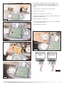
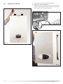
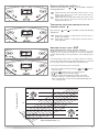
2.10.
FITTING THE MECHANICAL / DIGITAL
CLOCK
The ACO MFFI (Combi) boiler is supplied with a factory fitted
mechanical time clock. There is a digital clock available as an
optional extra (code: 706348).
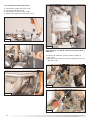
To fit the digital clock it is necessary to proceed as follows:1. Remove the outer casing
2. Open the control panel (see Section 2.22);
C2
C2
C2
FIG. 2.22
3. Unplug the electrical connection from the PCB and unscrew
the four screws (Fig. 2.26);
4. Remove the time clock (Fig. 2.27).
5. Connect the wires supplied with the clock to the digital time
clock as shown in Fig. 2.28;
6. Reassemble in reverse order.
NOTE: THE MECHANICAL CLOCK HAS FOUR WIRES, THEREFORE THE
HARNESS WILL REQUIRE CHANGING ALSO.
20
The ACO RFFI (System) boiler is not supplied with a clock,
however a mechanical and digital clock is available as an
optional extra (mechanical - code: 706349 and digital - code:
706348)
To fit the clock it is necessary to proceed as follows:1. Remove the outer casing
2. Open the control panel (see Section 2.22);
3. Unplug the electrical connection from the PCB and unscrew
the four screws (Fig. 2.26);
4. Remove the time clock (Fig. 2.27).
FIG. 2.23
5. Connect the wires supplied with the clock to the digital time
clock as shown in Fig. 2.28;
6. Reassemble in reverse order.
C3
C3
C4
C3
C3
FIG. 2.24
FIG. 2.27
DIGITAL
MECHANICAL
DIGITAL
FIG. 2.25
3
2
G B
MECHANICAL
5 4 3
1
R
G
2
B
1
R
FIG. 2.28
FIG. 2.26
21
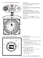
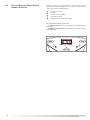
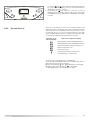
2.11.
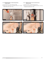
SETTING THE MECHANICAL TIME CLOCK
1. General layout
The mechanical clock covers a 24 hour period. Each tappet
represents 15 minutes A (Fig. 2.30). An override switch is
located on the clock B (Fig 2.30).
2. To set the time
To set the time of day, grasp the outer edge of the dial and
turn slowly clockwise until the correct time is lined up with the
arrow C (Fig. 2.30).
3. To Set the "On" and "Off" times
The clock uses a 24hours system. e.g. 8 = 8.00 am and
18 = 6.00 pm. "ON" periods are set by sliding all tappets
between the "ON" time and the "OFF" time to the outer edge
of the dial.The tappets remaining at the centre of the dial are
the "OFF" periods.
4. For operation
symbol to control the
Put the selector switch B to the
central heating by the clock. Put the switch B to «I» to select
permanent operation or to «0» to turn the central heating off
permanently.
Fig. 2.29
A
3
2
4
1
24
23
22
12
5
21
C
6
7
19
9
20
I
8
18
9
17
B
15
14
13
10
16
6
12
11
Fig. 2.30
Operating the time switch
The steps marked with the symbol “
out a switching program.
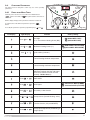
2.11.1. SETTING THE DIGITALTIME CLOCK
Manual switch
Summer and
winter time
setting
Reset
Enter
the hours
h
Prog
.
Enter
switching
times
Weekdays
flash
m
Imput
time
Day
Enter
weekday/s
22
Enter
minutes
” are necessary to carry
Preparing for Operation
Activate the “Res” switch (=RESET) to reset the time switch
to its default setting (activate using a pencil or similar
pointed instrument). Do this:
- every time you wish to “reset” the time switch
- to erase all switching times and the current time of day.
After approximately two seconds the following display
appears: “– – : – –”.
Enter current time and weekday
- Keep the “ ” key pressed down
During the summer time period press the +/- 1h key once.
Enter the hour using the “h” key
Enter the minutes using the “m” key
Enter the day using the “Day” key
1 = “Monday”..............7 = Sunday
- Release the “ ” key.
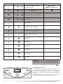
Automatic
Operation
Manual
Operation
Continuous
Operation
= ON
= ON
= Continuously ON
= OFF
= OFF
= Continuously OFF
The switching
times correspond to the
program
entered.
If the current
switching mode is
changed manually,
the next switching
time will be
carried out automatically again
according to the
entered switching
program.
You can only
return to automatic
mode from the
continuously-ON
and continuouslyOFF
switching
modes by
pressing the "
"
key.
Entering the switching times
You have 20 memory Iocations available. Each switching
time takes up one memory location.
Keep pressing the “Prog” key until a free memory location is
shown in the display “– –:– –”.
Programme ON or OFF with the “
” key:
“ ”= OFF; “ ”= ON
Enter the hour using “h”
Enter the minutes using “m”
If a switching command is to be carried out every day (1 2 3
4 5 6 7) then store using the “ ” key, otherwise select the
day(s) it is to be carried out by using the “Day” key.
When the day seIection is left bIank, the programmed
switching instruction operates at the same time every day
1 2 3 4 5 6 = Monday – Saturday
12345
= Monday – Friday
67
=Saturday – Sunday
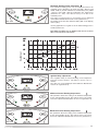
Changing the programmed switching times
Press the “Prog” key repeatedly until the switching time you want
to change is displayed. You can now enter the new data. See
point “Entering the switching times”.
Notes on storing switching times:
If you end your entry of the switching times by pressing the
“Prog” key, then the switching time you have entered will be
stored and the next memory location displayed.
In addition, a complete switching command is stored
automatically after around 90 seconds provided no other key
is pressed. The time switch then enters the automatic operating
mode and displays the current time again.
Deleting individual switching times
Press the “Prog” key repeatedly until the switching time you wish
to delete is shown in the display. Then set to “– –” using the “h”
or “m” key and keep the “ ” key pressed down for around 3
seconds. The switching time is now erased and the current time
is displayed.
AM / PM time display
If you press the “+/-1h” and “h” keys at the same time, the time
display switches into the AM/PM mode.
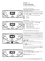
Selection of single days: 1 = Mon. .............. 2 =Tues.
Save the switching time with the “ ” key.
The time switch enters the automatic operating mode and
displays the current time of day.
Begin any further entry of a switching time with the “Prog”
switch. If your entry is incomplete, the segments not yet
selected will blink in the display. After programming is
completed, and you return the time clock to the current time
display with the “ ” key, the time clock will not activate any
switching instruction required for the current time. You may
need to manually select the desired switching state with the
“
” key. Thereafter, as the unit encounters fur ther
switching instructions in the memory in real time, it will
correctly activate all subsequent switching instructions.
Manual Override Switch “
”
With the “
” you can change the current setting at any time.
The switching program already entered is not altered.
Reading the programmed switching times
Pressing the “Prog” key displays the programmed switching
times until the first free memory location appears in the display
“– – : – –”.
If you now press the “Prog” key once again, the number of free
memory Iocations will be displayed, e.g. “18”. If all memory
locations are occupied, the display “00” appears.
23
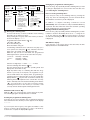
2.12.
ACCESSORY CONNECTION
IMPORTANT!!
Before carrying out any repairs to the appliance always
ensure that the external power supply has been isolated.
The boiler will remain live even when the ON/OFF knob is
in the “O”(off) position.
In order to gain access to the external control connections, it is
first necessary to remove the casing (as shown in Section 3.2)
then proceed as follows:
1. Remove the cover of the main PCB box (Fig 2.31).
2. Access can now be gained to the following connectors (see
Section 2.13):
CN10 - Safety thermostat for underfloor heating (SP)
CN 9 - Room Thermostat (TA)
CN 11 - Time clock
CN 6 - Interface PCB (FIG. 2.33)
FIG. 2.31
SP
TA
CONNECTION OF ROOM THERMOSTAT OR EXTERNAL
TIME CLOCK
a. - Insert the thermostat cable through the cable grommet
and fasten it by means of the cable-clamp provided.
b. - Connect the thermostat wires to the terminal block
CN9 (Fig. 2.32 - Diagram A).
IMPORTANT!!
Only remove the links from SP and TA if they are to be
connected to external controls.
c.- If a remote time clock is to be fitted, supply 240V from
the same spur as the boiler for the clock motor supply,
disconnect the integral time clock from the P.C.B.
CN11
d. - Using a volt-free switching time clock, connect the
switching wires from the time clock following points AC above (Fig. 2.32 - Diagram B).
e. - If using an external time clock and room thermostat,
these must be connected in series as points A-D
above (Fig. 2.32 - Diagram C).
NOTE: ENSURE LOW VOLTAGE AND HIGH VOLTAGE CIRCUITS ARE
CABLED SEPARATELY TO AVOID INDUCED VOLTAGES IN THE LOW
VOLTAGE CIRCUITS.
FIG. 2.32
24
FITTING THE EXTERNAL SENSOR
The exter nal sensor is supplied with the interface PCB
(Fig. 2.33).
The external sensor should be sited no more than 50 m from the
boiler and on an external north facing wall, between 2 and 2.5
metres above the ground. It should also be ensured that the
external sensor is positioned out of direct sunlight.
To connect the external sensor, plug the interface PCB into
connector CN6 on the main PCB (see Fig. 2.33).
To connect between the interface PCB and the external sensor,
it will be necessary to use 2x 0.5mm2 cable, connected to the
two terminals on the external sensor and to Terminal B (Fig.
2.33) on the interface PCB.
Instructions on the activation and setting of the outdoor sensor
are detailed on pages 41 and 42.
Parameter P activates the external sensor, Parameter P6
modifies the thermal curve and Parameter P6 selects the
specific thermal curve for the type of system installed.
NOTE: WHEN USING THE ACO BOILERS TO HEAT AN INDIRECT
CYLINDER, DO NOT USE THE EXTERNAL SENSOR AS THIS WILL
AFFECT THE RECOVERY TIME OF THE CYLINDER.
FIG. 2.33
25
CN4
CN1
CN3
N
VG
CN2
CN5
7 8 9 10 1112
CI
AC
CN12
CN1
WFS
1
CN8
CN11
FUSE
NTC1
NTC2
FS
CN10
7 8 9 10 1112
CN6
CN9
NTC3
PA
CN7
CN12
O
P
CN8
Day
CN11
h
MV
CN5
L
CN16
N
1
L
2
12 11 10 9 8 7 6 5 4 3 2 1
1
2
Nr
Mr
Rs
Bn
Az
2
Bl
Mr
1
Rs
Nr
Mr
Bl
R/N
Mr
Bl
Nr
Nr
1
4
TIMER
1
Bl
Bl
1
Gr
Gr
Bn
Bn
Gr
1
Bn
Bn
2
3
FIG. 2.31
FUSE
Gr
Gr
Gr
1
FLOOR ROOM
26
1
2
3
4
5
6
7
8
9
10
11
12
1
2
3
4
5
6
TA
CN9
A
TS
CN10
B
E
K
F
H
D
C
M
L
I
N
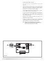
ELECTRICAL DIAGRAM
Pr og
.
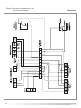
2.13.
The P.C.B. is fitted with 2 fuses, on the live and the
neutral.
The fuse holder contains:
- 5 x 20mm “3.15A Slow” glass fuses
m
Legend:
A
B
C
D
E
F
H
I
K
L
M
N
O
P
-
ON/OFF button
Green LED (Indicates burner on)
COMFORT button
Programming key +
Central Heating temperature adjustment
Menu button
Programming key Domestic Hot Water temperature adjustment (MFFI only)
Comfort function LED (yellow) (MFFI only)
Red LED (indicates lockout)
Multifunction display
Reset button
EEPROM key
Interface PCB (optional)
FS
NTC1 NTC2 NTC3 OP
VG
M
CI
MV
AC
PA
TA
TS
CR*
SE*
-
Domestic hot water flow switch
Central Heating flow temperature probe
Central Heating return temperature probe
Domestic Hot Water temperature probe
(mod. 27/32 MFFI)
Connection for boiler thermostat
(mod. 27/32 RFFI SYSTEM)
Time clock
Gas valve
Diverter valve (mod. 27/32 MFFI)
Circulation pump with automatic air release valve
Fan
Spark generator
Air pressure switch
Room Thermostat (optional)
Underfloor Heating Safety Thermostat (optional)
Remote Control (optional)
External sensor (optional)
* NOT SHOWN
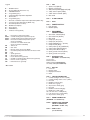
CN1 = FAN
1: Start of coil (black)
2: End of coil (brown)
3: “Hall” sensor power supply 12V (red)
4: “Hall” sensor input (white)
5: “Hall” sensor neutral (blue)
6: Not used
CN2 =
FLAME SENSOR
CN3 =
Earth
CN4 = POWER SUPPLY
1: Live (brown)
2: Neutral (blue)
EQUIPMENT
CONNECTIONS
1: Gas valve neutral (blue)
2: Gas valve live (brown)
3: Not used
4: Pump (V1) live (red)
5: Pump (V2) live (black)
6: Pump (ON/OFF) live (brown)
7: Pump neutral (blue)
8: 3-way valve (C.H.) (red/black)
9: 3-way valve (D.H.W.)(brown)
10: 3-way valve Neutral (blue)
CN5 =
11: Spark generator Neutral (black)
12: Spark generator live (black)
CN6 =
INTERFACE PCB
(OPTIONAL - see Section 2.12)
Accessories:
External sensor
Remote Control CLIMA MANAGER
Secondary outlet (see Section. 2.12)
CN7 = DISPLAY
1: Power 5V
2: Display return
3: Display transmission
4: Earth
CN8 = SENSOR CONNECTOR
1: Central Heating flow sensor (white)
2: Central Heating return sensor (white)
3: Not used
4: DHW flow switch (grey)
5: DHW sensor (grey)
6: Air pressure switch (grey)
7: Not used
8: DHW flow switch earth (grey)
9: DHW sensor earth (grey)
10: C.H. flow sensor earth (white)
11: C.H. return sensor earth (white)
12: Air pressure switch (grey)
CN9 = ROOM THERMOSTAT
(OPTIONAL - see Section 2.12)
CN10 = UNDERFLOOR HEATING
SAFETY THERMOSTAT
(OPTIONAL - Section 2.12)
CN11 = TIME CLOCK
(see Section 2.12)
27
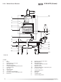
2.14. WATER CIRCUIT DIAGRAM
27/32 MFFI (Combi)
20
1
2
3
4
5
6
19
18
7
8
9
17
16
10
15
14
11
12
13
FIG. 2.32
A
B
LEGEND:
1 Fan
Burner
2 Ignition/detection electrode
3 4 Air release valve
5 Main heat exchanger
Central heating flow temperature probe
6 Condensate Trap
7 Gas valve
8 9 Pressure gauge
Safety valve
10 Secondary heat exchanger
11 Domestic hot water temperature probe
12 13 Drain valve
28
C
D E
14
15
16
17
-
18 19 20 A
B
C
D
E
-
Domestic hot water flow switch
Motorised valve
Automatic By-pass
Circulation pump with automatic
air release valve
Expansion vessel
Central heating return temperature probe
Air pressure switch
Central Heating Flow
DHW Outlet
Gas Inlet
Cold Water Inlet
Central Heating Return
27/32 RFFI (System)
FIG. 2.33
LEGEND:
1 Fan
Burner
2 Ignition/detection electrode
3 4 Air release valve
5 Main heat exchanger
Central heating flow temperature probe
6 Condensate Trap
7 Gas valve
8 9 Pressure gauge
Safety valve
10 Drain valve
11 Automatic By-pass
12 13 Circulation pump with automatic
air release valve
14 15 16 -
Expansion vessel
Central heating return temperature probe
Air pressure switch
A
C
E
Central Heating Flow
Gas Inlet
Central Heating Return
-
29
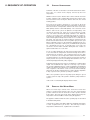
3. COMMISSIONING
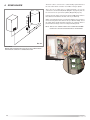
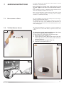
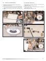
3.1.
INITIAL PREPARATION
Manual Air Vent
initiative. In Sections 11
MTS (GB) Limited support the
and 12 of this manual you will find the
commissioning
checklist (page 78) and the service interval record (Page 79), It
is important the
commissioning checklist is completed
in the presence of your customer, they are shown how to use it,
and it is signed by them. Please instruct your customer that they
must have this manual with them whenever they contact a
service engineer or us.
Preliminary electrical system checks to ensure electrical safety
must be carried out by a competent person i.e. polarity, earth
continuity, resistance to earth and short circuit.
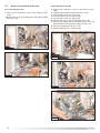
FILLING THE HEATING SYSTEM:
Remove the case and lower the control panel (see section 3.2.
for further information).
Open the central heating flow and return cocks supplied with
the connection kit.
Unscrew the cap on the automatic air release valve one full
turn and leave open permanently.
Close all air release valves on the central heating system.
Gradually open valve(s) at the filling point (filling-loop)
connection to the central heating system until water is heard to
flow, do not open fully.
Open each air release tap starting with the lowest point and
close it only when clear water, free of air, is visible.
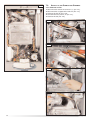
Purge the air from the pump by unscrewing the pump plug
and also manually rotate the pump shaft in the direction
indicated by the pump label to ensure the pump is free.
IMPORTANT!!
O PEN THE MANUAL
AIR VENT AND ENSURE THAT THE PRIMARY
EXCHANGER IS FREE OF AIR.
(See FIG. 3.1A)
Close the pump plug.
Continue filling the system until at least 1 bar registers on the
pressure gauge.
Inspect the system for water soundness and remedy any leaks
discovered.
FIG. 3.1A
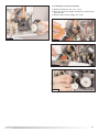
FILLING OF THE D.H.W. SYSTEM:
Close all hot water draw-off taps.
Open the cold water inlet cock supplied with the connection kit.
Open slowly each draw-off tap and close it only when clear
water, free of bubbles, is visible
GAS SUPPLY:
Inspect the entire installation including the gas meter, test for
soundness and purge, all as described in BS 6891:1988.
Open the gas cock (supplied with the connection kit) to the
appliance and check the gas connector on the appliance for
leaks.
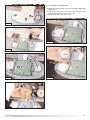
Water Treatment
The boiler is equipped with an aluminium alloy main heat
exchanger.
The detailed recommendations for water treatment are given in
BS 7593:1992 (Treatment of water in domestic hot water central
heating systems); the following notes are given for general
guidance:
- If the boiler is installed in an existing system, any unsuitable
additives must be removed;
- Under no circumstances should the boiler be fired before the
system has been thoroughly flushed; the flushing procedure
must be in line with BS7593:1992.
Firstly fill the central heating system and boiler with the power
30
off and flush through cold, fill the central heating system
again, add a flushing detergent, we highly recommend the
use of a flushing detergent appropriate for the metals used in
the aluminium alloy circuit. These include (Fernox Superfloc,
BetzDearborn Sentinel X300 or X400), whose function is to
dissolve any foreign matter that may be in the system, and
run the boiler on central heating until it reaches its operating
temperature, flush the system as instructed by the
manufacturer of the flushing detergent and refill the system
with a suitable corrosion inhibitor such as Fernox Copal MB1, or BetzDeaborn Sentinel X100 is recommended.
NOTE: FAILURE TO
CARRY OUT THE FLUSHING PROCEDURE WILL RESULT
IN THE WARRANTY BECOMING VOID.
In hard water areas or where large quantities of water are in
the system the treatment of the water to prevent premature
scaling of the main heat exchanger is necessary.
The formation of scale strongly compromises the efficiency of
the thermic exchange because small areas of scale cause a
high increase of the temperature of the metallic walls and
therefore add to the thermal stress of the heat exchanger.
Demineralised water is more aggressive so in this situation it
is necessary to treat the water with an appropriate corrosion
inhibitor.
- Any treatment of water by additives in the system for frost
protection or for corrosion inhibition has to be absolutely
suitable for all the metals used in the circuit including the
aluminium alloys.
- If anti-freeze substances are to be used in the system, check
carefully that they are compatible with the aluminium.
In particular, DO NOT USE ordinary ETHYLENE GLYCOL,
since it is corrosive in relation to aluminium and its alloy, as
well as being toxic.
MTS suggests the use of suitable anti-freeze products such
as Fernox ALPHI 11, which will prevent rust and incrustation
taking place.
Periodically check the pH of the water/anti-freeze mixture of
the boiler circuit and replace it when the amount measured is
out of the range stipulated by the manufacturer ( 7 < pH < 8).
DO NOT MIX DIFFERENT TYPES OF ANTI-FREEZE
- In under-floor systems, the use of plastic pipes without
protection against penetration of oxygen through the walls
can cause corrosion of the system’s metal parts (metal
piping, boiler, etc), through the formation of oxides and
bacterial agents.
To prevent this problem, it is necessary to use pipes with an
“oxygen-proof barrier”, in accordance with standards DIN
4726/4729. If pipes of this kind are not used, keep the
system separate by installing heat exchangers of those
with a specific system water treatment.
IMPORTANT
Failure to carry out the water treatment procedure will
invalidate the appliance warranty
31
3.2.
REMOVING THE CASING
A
To remove the front casing panel, follow these steps:
1. Remove the screws “A” (FIG 3.1);
2. Remove the four screws from case hooks (two at the top
and two at the bottom) and rotate anti-clockwise (FIG 3.2);
3. Lift and unhook the case panel (FIG 3.3).
A
FIG. 3.2
FIG. 3.1
FIG. 3.3
32
3.3.
CONTROL PANEL
27/32 MFFI (Combi)
I
A
H
G
B
F
C
E
D
FIG. 3.4
Button
Description
Description
ON/OFF Switch
A
Green LED
(illuminated = burner on)
“COMFORT” Function Push-button
B
Time clock
C
Selector knob for Summer/Winter
Central Heating Temperature Adjustment Knob
D
Control Panel Cover
E
Domestic Hot Water Temperature Adjustment Knob
F
Heating System Pressure Gauge
G
“COMFORT” Function L.E.D
H
Red LED
(illuminated = boiler lockout)
I
Multi-function Display
Reset Button/
Flue Test**/ scroll through Functions Menu
Menu Switch
Programming “+” key
Programming “-” key
** IMPORTANT!!
The Flue Test function will cause the boiler to run continuously on
maximum power. This function must only be activated by an
authorised engineer.
33
27/32 RFFI (System)
I
A
H
G
B
F
C
D
FIG. 3.4
Button
Description
Description
ON/OFF Switch
Not used
Reset Button/
Flue Test**/ scroll through Functions Menu
Menu Switch
A
Green LED
(illuminated = burner on)
B
Time clock (Optional Extra)
C
Central Heating Temperature Adjustment Knob
D
Control Panel Cover
F
Heating System Pressure Gauge
G
Heating only L.E.D
H
Red LED
(illuminated = boiler lockout)
I
Multi-function Display
Programming “+” key
Programming “-” key
** IMPORTANT!!
The Flue Test function will cause the boiler to run continuously on
maximum power. This function must only be activated by an
authorised engineer.
34
3.4.
INITIAL START-UP
H
C
FIG. 3.5
1. Make sure that:
- the cap of the automatic air release valve is loosened;
- the system pressure is at least 1 bar on the
pressure gauge “F” (Fig. 3.4);
- the gas cock is closed (Fig. 3.7);
- the electrical connection has been carried
out in the correct manner.
To allow the air to escape from the system,
FIG. 3.7
proceed as follows:
- push the On/off button
and turn the
knob “C” (Fig. 3.5) to the “winter” position. The boiler pump will
start up and three consecutive attempts will be made to ignite
the burner. After the third attempt, the electronic system will
shutdown the boiler, because the supply of gas has been cut off.
The message “A01” will appear on the display and the red LED
“H” will illuminate;
- let the pump operate until all the air has escaped from the
system;
- repeat the procedure for bleeding the radiators of air;
- draw hot water for a short while;
- check the system pressure and, if it has gone down, fill it with
water until it returns to 1 bar.
2. Fill the boiler condensate trap with water, by pouring 1/2 a
litre of water into the exhaust flue connector (see Section
2.9 Connecting the Flue).
N.B. In the event of a prolonged period of system shutdown,
the condensate trap should be filled before any renewed
use. A shortage of water in the trap could temporarily lead
to a small leakage of fumes into the air.
3, Ensure that the flue is fitted correctly.
4. Turn on the gas cock (Fig. 3.8) and check
the seals on the connections, including the
one for the burner, making sure that the
meter does not signal the passage of gas.
Check the connections with a soap solution
and eliminate any leaks.
Fig. 3.8
FIG. 3.6
5. Press the reset button
, the boiler will attempt to light.
If the burner does not light the first time, repeat the procedure.
Note: Should the boiler fail to ignite check that no air is present in
the gas pipe.
The boiler is configured in the factory for the gas type in
question. To check the CO2 setting, please refer to Section
3.6.3.
6. Run the appliance in the DHW mode and check the correct
operation of the thermostat control.
7. Complete the
commissioning checklist.
35
3.5.
DISPLAY: MESSAGES SHOWN DURING
NORMAL OPERATION
During operation of the boiler, while it is carrying out its normal
operations, the left-hand display shows a series of characters that
refer to the operations indicated below:
0
C
c
d
h
No request for heat
Heating
Pump overrun for heating
Domestic hot water
Pump overrun for domestic hot water
The right-hand display (two-digit) shows:
- in CENTRAL HEATING mode: temperature of the Central Heating
system flow;
- in DOMESTIC HOT WATER mode: temperature of the Domestic Hot
Water (MFFI only).
LEFT
FIG. 3.9
36
RIGHT
3.6.
OPERATING PARAMETERS
The boiler has been designed to allow easy use of the operating
parameters.
3.6.1
REGULATION MENU TABLE
Summary of the functions accessed when the RESET button
and the menu button
are pushed at the same time for
5 seconds.
On the display will appear the parameters indicated on table 3A.
To switch between the different parameters press the
button.
To modify the parameters push the programming keys
and
Fig. 3.10
.
left display
right display
function
factory setting
1
from 0 to 99
Soft light
as % of maximum Heating Power (NG)
60 (ACO 27 MFFI - RFFI )
43 (ACO 32 MFFI - RFFI )
2
from0 to 99
Maximum Heating Power (%)
3
from 0 to 7
Ignition delay (minutes)
02
4
Central heating minimum temperature
46
5
Central heating maximum temperature
82
6
PDT rpm (Check of the temperature
difference between the flow and return
sensors for twelve seconds on initial
start-up - DO NOT ADJUST)
45
55 (ACO 27 MFFI - RFFI SYSTEM)
52 (ACO 32 MFFI - RFFI SYSTEM)
t
fromS0 to S1
NOT USED
S0
F
fromO0 to 02
Boiler types
00 - ACO 27 /32 MFFI (COMBI)
02 - ACO 27/32 RFFI (SYSTEM)
e
from00 to 03
Secondary outlet function
p
from01 to15 or CO Pump overrun (Central Heating - mins)
00
02
c
from00 to 01
Comfort function (only model MFFI)
01
p
fromU0 to U1
Pump speed adjustment (modulating or
single speed)
U1
TABLE. 3A
37
left-hand display
right-hand display
r
from00 to 01
p
from90 to 91
p6
from-20 to +20
Correction of heat curve translation
P5
from 0_3 to 3_0
Curve incline
t
A
Function
selects low temperature systems
or standard systems
Temperature regulation controlled by
external sensor
factory setting
01 Standard
00 Low Temperature
90
Test Function
81
Bus Address (Do not modify)
b0
Set-point second heating zone
b1
GSM value (Do not modify)
b
20
NOT USED
b
30
NOT USED
b
40
NOT USED
b
50
NOT USED
b
60
NOT USED
b
70
NOT USED
Important!!
The parameters P5 and P6 are only enabled when the
outdoor sensor is activated (Parameter P - page 41).
To return to the normal display, press the menu button
.
Soft Light adjustment 1
FIG. 3.11
38
The soft light can be adjusted between the maximum power
(shown on the display as “00”, i.e. 100%) and the minimum
power (shown on the display as “01”, i.e. 1%). The boiler is
factory set to a value which is suitable for the ignition with any
type of gas.
The value set expressed as a percentage, can be displayed and
adjusted as indicated in Section 3.6.1 (parameter 1)
Maximum Heating Power adjustment 2
The maximum heating power can be adjusted between the
maximum power allowed by the boiler (22.5kW - ACO 27 and
28kW - ACO 32) and the minimum recommended power (10kW
- ACO 27 and 13kW - ACO 32) indicated in the graph below
(Parameter 2 = 20%). The value is factory set to 70% of the
maximum power.
The value set (expressed as a percentage) can be displayed
and modified as illustrated in Section 3.6.1 (parameter 2).
The display shows the value between 100% ("00" on the display)
and 1% ("01").
FIG. 3.12
Use the graph below as a guide to set the boiler heating power to
suit the system load.
NOTE: MTS RECOMMEND THAT THE MINIMUM
20% AS INDICATED IN THE GRAPH BELOW..
POWER NOT BE SET BELOW
Heat Output
ACO 32
ACO 27
Display
Ignition Delay adjustment
3
The re-ignition delay for Central Heating can be adjusted to
between 0 and 7 minutes. The delay is factory set to 2
minutes.
The value set can be displayed and modified as illustrated in
Section 3.6.1 (parameter 3)
FIG. 3.13
Minimum Central Heating temperature
4
This parameter allows the setting of the minimum temperature
for the central heating circuit. The value is factory set at 46°C
and can be adjusted as illustrated in Section 3.6.1 (parameter 4).
FIG. 3.14
Maximum Central Heating temperature
5
This parameter allows the setting of the maximum temperature
for the central heating circuit. The value is factory set at 82°C
and can be adjusted as illustrated in Section 3.6.1 (parameter 5).
FIG. 3.15
39
Boiler types
F
Factory setting:
00 - ACO 27 / 32 MFFI (COMBI)
02 - ACO 27 / 32 RFFI (SYSTEM)
THIS PARAMETER MUST NEVER BE ADJUSTED.
Secondary outlet Function E
(This parameter can be modified only with the
interface PCB connected)
With the interface PCB connected, it is possible to set the boiler
to operate with one of the following accessories, (see Section
2.12 for further information). The setting can be varied by
pushing the
and
keys, the following options are available:
00
01
02
03
FIG. 3.16
zone valve - factory setting - (NOT USED IN UK)
NOT USED
NOT USED
NOT USED
PUMP OVERRUN
P
The pump overrun time may be adjusted (after the burner has been
turned off) by pressing the programming keys
and
.
The following modes are available:
01
1 minute of pump overrun
03
3 minutes of pump overrun - factory setting
06
6 minutes of pump overrun
09
9 minutes of pump overrun
12
12 minutes of pump overrun
15
15 minutes of pump overrun
CO
Continuous pump overrun (NOT RECOMMENDED)
FIG. 3.17
Comfort Function (MFFI model - Combi only) C
FIG. 3.18
K
D
The boiler allows the convenience level to be increased in the output
of domestic hot water by means of the “COMFORT” function. This
function keeps the secondary exchanger warm during the periods in
which the boiler is inactive, thereby allowing the initial water drawn to
be at a higher temperature.
The function may be activated by pressing the COMFORT button
key on the control panel (see section 3.3.). When the function is
active, a yellow light “G” comes on, again located on the control
panel.
The comfort function can be activated or deactivated by pressing
the
and
keys
00 Comfort function deactivated
01 Comfort function active for 30 minutes - factory setting.
It is possible to deactivate the comfort function by pressing the
button
.
The yellow LED “G” will go out.
N OTE : During the overrun period of the pump, the “COMFORT”
function, if selected, is temporarily deactivated. The L.E.D. light
remains on to indicate that the boiler will return to the “COMFORT”
mode once the pump overrun has finished.
Pump Speed Adjustment P
By pressing the
and
keys it is possible to adust the
operation of the pump, the two options are as follows:
U0 - Single Speed Pump
U1 - Modulating Pump - factory setting
FIG. 3.19
40
SETTING THE TEMPERATURE FIELD r
Using the programming keys
and
it is possible to make the
following adjustments:
00” signifies that the flow temperature (which may be set by
“0
means of the knob on the front control panel) may be
regulated from 20 to 75°C.
01” signifies that the flow temperature (which also may be set by
“0
means of the knob on the front control panel) may be
regulated from 46 to 82 °C.
FIG. 3.20
TEMPERATURE REGULATION CONTROLLED BY THE
EXTERNAL SENSOR P
By pressing the
and
it is possible to make the following
adjustments:
90” Temperature regulation controlled by the external sensor is
“9
inactive (not installed).
91” Temperature regulation controlled by the external sensor is
“9
active (installed).
FIG. 3.21
ADAPTING THE HEAT CURVE “P 6”
(Only enabled when the outdoor sensor is activated)
Should the external sensor be fitted it will be necessary to set the
heating curve (see page 41) and may be necessary to adjust the
parallel shift depending on the performance of the heating system
used.
FIG. 3.25
If the temperature in the house is too high, it will be necessary to
decrease the parallel shift, whereas if the temperature is too low it will
be necessary to increase the parallel shift as described below.
To set up the external sensor proceed as follows;
1. Access the settings menu by pressing the
and
buttons
for five seconds;
2. Press the
button 5 times to access Parameter 6
3. P 6 will now appear in the left hand display
4. Adjust the parallel shift by turning the heating control knob
clockwise to increase or anti-clockwise to decrease as shown
below. The shift value can be read on the right hand display, from
-20 to +20 (Fig. 3.26).
FIG. 3.26
Flow temperature (°C)
100
-20
+20
rea
inc
o
t
60
se
cu
t he
rv
6
lel
r al
a
np
ei
el
20
to
+20
se
rea
ec
n
ei
ur v
c
the
l
ral
pa
-20
+20
d
External temperature (°C)
-20
41
SETTING THE CURVE INCLINE P 5
(Only enabled when an outdoor sensor is installed)
When using an outdoor sensor, the microprocessor-controlled P.C.B.
calculates the most suitable flow temperature, taking into account
the exter nal temperature and the type of system. The
microprocessor is capable of doing this because it is possible to
establish a link between the external temperature and the flow
temperature of the Central Heating system water. This link translates
into a "thermal curve".
The type of curve should be chosen in correspondence with the
planned temperature of the system and the nature of the heat loss
present in the building.
FIG. 3.27
To select the type of curve access the Setting Menu by pressing the
and
buttons for 5 seconds and proceed as follows;
1. Press the
button four times to access Parameter 5;
2. P 5 will be shown on the left hand display;
3. Choose the curve required for the system from Fig. 3.31 and
select by pressing the
and
buttons.
FIG. 3.28
Fig. 3.31
With parameter P5 it is necessary to adjust the heat curve to one
of those shown in Fig. 3.31. By using the programming keys
and
, the curve may be changed to select the required curve
for the system.
The curves that can be selected are as follows:-
Convector radiator
Steel radiator
Oversized steel radiator
Under-floor heating
Curve 2.5 to 3
Curve 1.5 to 2
Curve 1 to 1.2
Curve 0.3 to 0.5(*)
WARNING
(*) - If curve 0_3 or 0_5 is selected, a system
safety thermostat must be connected to the
main terminal board (see paragraph 2.12)
Test Function
t
The test function is used to enable the engineer/installer to check
the combustion rate (see Section 3.6.3).
The P.C.B. allows the boiler to be forced to the maximum or
minimum power. Enable the test function, two dashes will appear on
the right-hand display (see Fig. 3.29).
max power Central Heating
FIG. 3.29
To select operation at maximum power, press the programming key
, two dashes will appear at the top of the right-hand display (see
Fig. 3.30).
This function is disabled when you press reset key to quit the
adjustments menu.
To select operation at minimum power, press the programming key
, two dashes will appear at the bottom of the right-hand display
(see Fig. 3.30). This function is disabled when you press reset key
“H” to quit the adjustments menu.
minimum power
42
FIG. 3.30
Note: The boiler can be forced to the maximum and minimum power
even without enabling the test function via the adjustments
menu:
a - by pressing the Reset key for 5 seconds, the boiler is
automatically forced to test mode and t-- will be displayed, the
boiler is now in the test mode for the maximum heating power, to
force the boiler to maximum output for hot water it is necessary
to press the
and
keys together, two dashes appear at the
top of the right-hand display (see Fig. 3.29). This function is
disabled by pressing the reset key .
b - by pressing the
key, the boiler is forced to operate at
minimum power, two dashes appear at the bottom of the righthand display (Fig. 3.31). This function is disabled by pressing the
reset key.
max power DHW
3.6.2
SETTINGS DISPLAY
FIG. 3.32
The boiler is designed to monitor some operating variables and
settings by means of the display on the front control panel. Keeping,
at the same time, the reset and the menu key pressed for over 10
seconds will allow access to the “readout” function of the main
system variables. By pressing the reset button repeatedly after that,
it is possible to read the following information in sequence:
Indication on the
left-hand display
Value read on right-hand display
U/1
Flow temperature of the Central Heating circuit (°C)
U/2
Return temperature of the Central Heating circuit (°C)
U/3
Domestic Hot Water output temperature (°C)
U/4
Outdoor temperature (°C)*
U/6
Fan speed (% rpm)
E
Last safety shut-off (see section 3.10.)
A
Last shutdown (see section 3.10.)
To return to the normal display, press the menu key.
The boiler will automatically return to the normal display after no
buttons have been pressed for 2 minutes.
U” and “1
1” blink alternately on the display
NOTE 1: U/1 means that “U
00” on the display
NOTE 2: the value 100% appears as “0
* = Only displayed when an external sensor is fitted.
43
3.6.3 GAS REGULATION CHECK
Supply pressure check
1. Loosen screw “1” (Fig. 3.33) and connect the pressure gauge
connection pipe into the test point.
2. Turn the boiler on at maximum power, enabling the “flue sweep”
function (press the
key for 5 seconds and then press the
programming keys
and
together ensuring the dashes are
at the top of the display (see Fig. 3.30). The supply pressure
should correspond to that shown for the type of gas the boiler is
designed for methane gas G20 (see table below).
3. Disable the test mode by pressing the reset key.
4. When the check is over, tighten screw “1” and test for tightness.
Analysis cover plate
NOTE: IF THE WORKING PRESSURE IS INSUFFICIENT CHECK THE GAS
METER, METER GOVERNOR, OR INSTALLATION PIPEWORK FOR
ERROR.
FIG. 3.32
4
3
SETTING THE GAS PRESSURES
2
IMPORTANT!
D O NOT
PROCEED CHECKING AND ADJUSTING THE
CO 2
SETTINGS
UNLESS THE WORKING PRESSURE IS ADEQUATE.
NOTE: ALL SETTINGS ARE TO BE MADE WITH A CO2 METER WITH THE
PROBE FITTED TO THE FLUE GAS ANALYSIS POINT.
1
2
3
4
1
FIG. 3.33
SUPPLY PRESSURE (WORKING)
G20 methane
G31 propane
20 mbar
37 mbar
TABLE 4D
CO2 SETTING MAXIMUM VALUE
CO2 at maximum power
% vol
% vol
8.7 ±0.2 (NG)
10.2 ±0.2 (LPG)
CO2 SETTING MINIMUM VALUE (NAT GAS)
CO2 at minimum power
% vol
% vol
9.2 ±0.2 (NG)
10.6 ±0.2 (LPG)
Setting the CO2 at minimum power
To check the air/gas ratio at minimum power, proceed as follows:
1. Connect the combustion analyser to the analysis point (Fig.
3.32) after removing the cover plate.
2. Set the boiler to minimum power via the test function (see
paragraph 3.6.1) or by pressing the
button for 5 seconds
and then pressing the
button on the control panel, ensure
the dashes are at the bottom of the display (see Fig. 3.30).
Ensure the CO2 value on the analyser corresponds with the
value indicated in table 4D. If this is not the case, adjust screw
“2” (Fig.3.33) with a screwdriver in small intervals, allowing the
reading to become stable before adjusting further, until you
obtain the correct CO2 reading. Allow the reading to become
stable for at least 4 minutes.
3. When the check is over, replace the cap on screw “2” (Fig. 3.33).
4. Disable operation at minimum power by pressing the
key
or press the
key to check the maximum value (dashes at top
of display see Fig. 3.31).
While the appliance is operating at maximum power, check
the gas rate of the appliance at the gas meter
Setting the CO2 at maximum power
To check the air/gas ratio at maximum power, proceed as follows:
1. With the combustion analyser already connected to the analysis
point, set the boiler to maximum power via the test function (see
paragraph 3.6.1) or by pressing the
button for 5 seconds
and then the programming keys
and
ensuring the dashes
at the top of the display (see Fig. 3.30).
Ensure the CO2 value on the analyser corresponds with the
value indicated in table 4D. If this is not the case, adjust screw
“4” with a screwdriver in small intervals allowing the analyser
reading to stabilise before adjusting further (Fig. 3.33), until you
obtain the correct CO2 reading. Allow the reading to become
stable for at least 4 minutes.
2. Disable the test mode by pressing the
button.
The test mode is automatically disabled after 5 minutes.
3. Repeat the air/gas ratio at minimum power check (see
above).
4. Disconnect the analyser, remount the cover plate and check it is
securely in place.
While the appliance is operating at minimum power, check
the gas rate of the appliance at the gas meter
NOTE: WHEN MAKING ADJUSTMENTS, ADJUST SMALL AMOUNTS AND
WAIT FOR THE ANALYSER TO STABILISE BEFORE MAKING
FURTHER ADJUSTMENTS.
44
3.6.4 IGNITION DELAY ADJUSTMENT
The ignition delay can be adjusted to between 0 and 7 minutes. The
delay is factory set to 2 minutes.
The value set can be displayed and modified as illustrated in
paragraph 3.6.1 (parameter 3).
3.6.5 ADJUSTING THE MAXIMUM HEATING POWER
The maximum heating power can be adjusted between the
maximum power allowed by the boiler (22.5kW - ACO 27 and 28kW
- ACO 32) and the minimum recommended power (10kW - ACO 27
and 13kW - ACO 32) indicated in the graph (parameter 2 = 20). The
value is factory set to 70% of the maximum power.
The value set (expressed as a percentage) can be displayed and
modified as described in paragraph 3.6.1 (parameter 2) using the
graph on Page 39.
NOTE: MTS RECOMMEND THAT THE MINIMUM
20% AS INDICATED IN THE GRAPH BELOW.
POWER NOT BE SET BELOW
3.6.6 SOFT LIGHT ADJUSTMENT
The soft light can be adjusted between the maximum power (shown
on the display as "00", i.e. 100%) and minimum power (shown on
the display as "01", i.e. 1%). The boiler is factory set to a value which
is suitable for ignition with any type of gas.
The value set (expressed as a percentage) can be displayed and
modified as illustrated in paragraph 3.6.1 (parameter 1).
3.7 CHANGING THE TYPE OF GAS
It is not possible to convert the ACO 27 & 32 MFFI/RFF to LPG.
A specific LPG version is available as the following codes:
ACO 27 MFFI: 537061
ACO 27 RFFI: 537063
ACO 32 MFFI: 3300005
ACO 32 RFFI: 3300007
3.8 ADJUSTING THE HOT WATER FLOW RATE
To adjust the hot water flow rate, it is necessary to first open the hot
water tap with the highest flow rate (normally the bath tap), adjust
the cold water inlet valve until the correct temperature rise is
achieved at the stated flow rate (ACO 27 MFFI - D T=35°C @ 10.8
l/min and ACO 32 MFFI - D T=35°C @ 13.1 l/min.
Alternatively, you can advise the customer to restrict the water flow
through each individual tap, by opening the tap and slowly closing it
until the water reaches the desired temperature.
3.9 BALANCING THE CENTRAL HEATING SYSTEM
To balance the central heating system it is first necessary to close
all radiator valves on the system, turn on the central heating, allow
the boiler to reach operating temperature and then starting at the
radiator furthest from the boiler, open the radiator valves until the
radiator becomes hot and move to the next radiator on the circuit,
working your way back to the radiator closest to the boiler.
45
3.10
BOILER SAFETY SYSTEMS
The boiler is protected from malfunctioning by means of internal
checks by the P.C.B., which brings the boiler to a stop if necessary.
In the event of the boiler being shut off in this manner, a code
appears on the display which refers to the type of shut-off and the
reason behind it.
There are two types of shut-off:
-
SAFETY SHUTDOWN: for this group of errors (characterised
E”) the situation is automatically
on the display by the letter “E
removed as soon as the cause behind it is resolved.
As soon as the origin of the shutdown disappears, the boiler
starts up again and returns to its normal operation.
A”), is
SHUTDOWN: (characterised on the display by the letter “A
not removed unless a manual intervention is made.
The boiler may return to operation only if reset, press the
button located at the centre of the display.
There follows a list of the shutdown modes and the respective codes
shown on the display.
A” type): if such a situation occurs, it is necessary to
Shutdown (“A
reset the boiler using the appropriate key. If this shutdown occurs
frequently, your local Service Agent should be contacted.
-
Safety shutdown: In the event that a safety shutdown occurs, it is
necessary to contact an Authorised Service Centre.
DISPLAY
DISPLAY
CAUSE
A01
Too many attempts to ignite on start up
E 04
Domestic hot water temperature probe
in open circuit
A02
No water or no water circulation in central
heating system
E 05
Domestic hot water temperature probe
in short circuit
A03
The heating flow temperature exceeds 105°C
during operation
E 06
Heating flow temperature probe in open circuit
A07
Too many failures to ignite in one period
during operation
E 07
Heating flow temperature probe in short-circuit
A33
Problem with the fan
E 08
Heating return temperature probe
in open circuit
A97
Problem with the electronic monitoring
E 09
Heating return temperature probe
in short-circuit
A98
Problem with the electronic monitoring
E 10
Under floor heating temperature probe
in open circuit
A99
Problem with the electronic monitoring
E 20
Flame detected with gas valve closed
E 30
Outdoor sensor open circuit
E 31
Outdoor sensor in short circuit
E 33
Fan operation sensed with no demand for
central heating or domestic hot water
NOTE:
When there is no ignition (A01), check that the gas cock is
open and gas is available.
DISPLAY
46
CAUSE
CAUSE
S01
Ignition failure on 1st attempt
E 34
Fan operation but air pressure switch
does not close
S02
Ignition failure on 2nd attempt
E 80
Remote Control CLIMA MANAGER room
sensor in open circuit or short circuit
E 94
Problem within the electronic system
E 95
Error reading flow or return temperature probe
E 99
Problem within the electronic system
DAILY TEST.
In order to prevent sticking components, the boiler carries out a selfdiagnosing test every 21 hours: the pump runs for 15 seconds and
the diverter valve moves once.
ANTI-FROST DEVICE.
The anti-frost function acts on the central heating flow temperature
probe, independently from other regulations, when the electrical
supply is turned on.
If the primary circuit temperature falls below 8°C the pump will run
for 2 minutes.
After the two minutes of circulation (fixed) the boiler will check the
following:
a) if the central heating flow temperature is > 8°C, the pump stops;
b) if the central heating flow temperature is between 3 and 8°C, the
pump will run for another two minutes;
c) if the central heating flow temperature is < 3°C, the burner will fire
(heating position) at minimum power until the temperature reaches
33°C, the burner will go out and the pump will continue to run for two
minutes.
If the flow temperature remains between 3-8°C the pump will
continue to run for two minutes for a maximum of 10 times unless a
temperature above 8°C is detected in the central heating flow, after
this the the burner will fire.
If lockout is caused by overheat the burner is kept OFF.
NOTE: In all cases, the circulation takes place in the central
heating system.
The anti-frost device activates only when (with the boiler
operating correctly):
- the system pressure is correct;
- the boiler is electrically powered;
- there is a supply of gas.
ANTI-SCALE DEVICE.
When producing domestic hot water, the burner shuts off
whenever the output temperature of the hot water exceeds
61°C or the flow temperature of the primary circuit exceeds
78°C. It will not turn on if the temperature of the primary circuit
is greater than 78°C.
3.11
COMPLETION
For the Republic of Ireland it is necessar y to complete a
“Declaration of Conformity” to indicate compliance to I.S. 813. An
example of this is given in the current edition of I.S. 813. In addition
commissioning checklist
it is necessary to complete the
(Section 11, page 78).
3.12
DRAINING
The draining of the heating system must be carried out as follows:
- Turn off the boiler and the bipolar switch;
- Loosen the automatic air release valve;
- Open the system's discharge valve
- Empty out from the lowest points of the system (where
provided).
If the system is to be left active in areas where the room
temperature may go below 0°C during winter, it is recommended
that anti-freeze liquid be added to the water in the heating system in
order to avoid the need for repeated draining.
Draining the domestic hot water system
Every time that there is a danger of freezing, the domestic hot water
system must be drained as follows:
- close the water mains stop-cock;
- open all the hot and cold water outlets;
- empty out from the lowest points (where provided).
47
4. ZONE VALVES
The boiler can be connected to a central heating system that uses
two zone valves allow connection to an indirect storage cylinder.
There are two possible types of wiring diagram, one for the
connection to an Unvented Cylinder (Diagram. A, page 49) and one
for connection to an open vented cylinder (Diagram B, page 50).
In both cases the boiler connection is shown as TA, which relates to
the terminal on the PCB for external controls (see FIG. 4.2).
When connecting the boiler to an external cylinder it is necessary to
remove the integral clock from the boiler (see SECTION 7.6.3), do not
run 240V cables and the TA cables together, use separate cables to
prevent induced voltage on the low voltage switching circuit.
NOTE: THE USE OF A ‘Y’ PLAN SYSTEM IS NOT POSSIBLE WITH THE ACO
BOILER DUE TO THE LOW VOLTAGE SWITCHING OF THE APPLIANCE.
FIG. 4.1
IMPORTANT!!
ENSURE THAT A BALANCING VALVE IS FITTED ON THE CYLINDER RETURN
AND BALANCED CORRECTLY AT COMMISSIONING STAGE.
FIG. 4.2
SP
TA
48
WIRING DIAGRAM FOR CONNECTION TO AN ARISTON
UNVENTED CYLINDER
DIAGRAM A
49
WIRING DIAGRAM FOR CONNECTION TO AN
OPEN VENTED CYLINDER
50
DIAGRAM B
5. SEQUENCE OF OPERATION
5.1
CENTRAL HEATING MODE
Activation of the time clock and/or room thermostat starts the boiler.
The letter C is shown in the display followed by the flow
temperature.
With the boiler in rest, the diverter valve is in the domestic hot water
position, activation of the central heating changes the position of the
motorised valve head, moving the diverter valve into the central
heating position.
The star t of the pump is delayed for 7 seconds to allow the
movement of the diverter valve (when the pump starts it at speed 2).
There then follows a temperature and flow rate check on the flow
NTC (NTC1) and the return NTC (NTC2). The electronics check
NTC’s 1 and 2 for the correct D T (difference in temperature). The
D T must be less than 5oC. If this is not correct after 40 seconds,
error code E95 is shown but the pump continues to run. When the
check is correct the boiler automatically starts the sequence.
Following the satisfaction of the temperature/NTC check the fan
starts and an ignition attempt is then made for 3 seconds after the
fan starts. The gas valve is energised and gas is delivered to the
burner fixed in relation the the fan. The ignition gas pressure (soft
light) is adjusted at Step 1 in the parameter adjustment mode (see
Section 3.6.1). This value is factory set. (1= minimum fan speed and
00 = maximum fan speed). Soft light takes 4 seconds, the
electronics check for flame ionisation during this time. Failure on
ignition results in the error code A01.
For 12 seconds following the gas valve being energised, the ignition
is checked and the temperature and flow through the boiler is
monitored by the electronics. The D T must increase by more than
50oC. To check the correct temperature and flow the boiler remains
at a fixed output for 5 seconds, this value is 50 and can be viewed at
Step 6 (Section 3.6.1.) Incorrect readings will result in the error code
A02 being displayed and the pump stopping.
Following all checks the boiler is free to modulate the central heating
output. The maximum heat output is set at Step 2 (see Section
3.6.1) and is adjustable between 1 and 00 (minimum and maximum
output). The burner can activate up to a maximum of the set point at
+4oC. reignition of the burner occurs once it has thermostatically
turned off can be time delayed between 0 and 7 minutes, adjustable
in Step 3 (Section 3.6.1), the factory setting is 2 minutes.
After correct operation is proven the pump speed changes to speed
3 (if the system is cold), if the system is warm the pump remains at
speed 2.
In the event of overheating the display will show A03.
5.2
DOMESTIC HOT WATER MODE
When a hot water tap is turned on the domestic hot water flow
switch is operated (if the diverter valve is in the central heating
position it will motor into the domestic hot water position and the
boiler starts. The letter d is shown in the display followed by the
temperature of the domestic hot water leaving the appliance.
The appliance will then follow the same operating logic as described
in Central Heating Mode.
In domestic hot water mode NTC1 limits the maximum temperature
to 78 oC, reignition will occur at 74 oC. The domestic hot water
temperature is limited to 61oC, reignition will occur at 60oC.
51
6. MAINTENANCE
6.1.
To ensure the validity of the 5 Year Guarantee, the boiler must be
serviced annually by a CORGI registered gas engineer.
GENERAL REMARKS
Provided the boiler was registered within the terms stated on the
guarantee card, MTS (GB) Limited will write to the householder as
the boiler becomes due for it’s annual service.
IMPORTANT!!
Every time that the combustion chamber cover or the
primary heat exchanger is removed from the boiler, the
combustion chamber seal must be checked and where
necessary replaced (code: 65102217). The silicone
grease provided with the gasket must be spread
around the area the gasket fits to ensure an airtight
seal.
Only the grease provided must be used, however,
should more grease be needed it must have a
temperature range of between –40 deg C and +200
deg C”
DO
The requirements stated in the letter must be adhered to in order to
ensure the continuation of the 5 year guarantee.
See Section 10 for annual maintenance requirements.
Note: Failure to comply with the annual service
requirements will result in the 5 year guarantee
becoming void.
NOT OPERATE THE BOILER WITH THE FRONT COMBUSTION
CHAMBER PANEL REMOVED!
FAILURE
TO OBSERVE THIS WILL
DAMAGE THE FAN AND AIR PRESSURE SWITCH AND WILL
INVALIDATE ANY WARRANTY.
6.2.
CLEANING THE PRIMARY EXCHANGER
CLEANING THE EXHAUST SIDE
Remove the combustion chamber inspection hatch (see section
7.3.5). Check that the exhaust passages between the blades of the
block are free; if there are deposits present, wash the blades with
compressed air, water or a vinegar-based detergent.
NOTE: it is possible to use a brush in order to mechanically remove
the residues.
Use of detergents:
soak the blades well
allow the detergent to act for about 20 minutes
rinse with a strong jet of water to remove the deposits (the
control panel must be kept closed)
make sure that there are no traces of detergents in the
exchanger.
CLEANING THE WATER SIDE
Use detergents that dissolve CaCO3. Leave to act for a short time
(in order not to damage the aluminum) and then rinse. Make sure
that the detergent does not remain inside the exchanger.
6.3.
CLEANING THE CONDENSATE TRAP
IMPORTANT!!
If the boiler is not to be used for a prolonged period, the
condensate trap should be filled before operating the
boiler. A shortage of water in the trap will temporarily
risk flue gasses escaping into the room.
To clean the condensate trap it is simply necessary to unscrew the
lower part of the condensate trap and clean it. Lastly, fill it with water
and replace the stopper.
6.4.
After having carried out the maintenance operations, fill the
heating circuit to a pressure of approx. 1.5 bar and release the
air from the system. Also fill the domestic hot water system.
Place the boiler in operation;
If necessary, release the air again from the heating system.
Check the settings and the correct functioning of all the
control, regulation and monitoring parts;
Check the seal and the correct functioning of the system for
expelling fumes/drawing of combustion air;
Check that the boiler ignites properly and carry out a visual
check on the burner flame;
-
52
OPERATIONAL TEST
Check the CO2 values are correct (see Section 3.6.3)
7.
To ensure efficient safe operation, the boiler must be serviced
annually by a competent person.
SERVICING INSTRUCTIONS
Before starting any servicing work, ensure both the gas and
electrical supplies to the boiler are isolated and the boiler is
cool.
Before and after servicing, a combustion analysis should be made
via the flue sampling point (please refer to 3.6.3).
After servicing, preliminary electrical system checks must be carried
out to ensure electrical safety (i.e. polarity, ear th continuity,
resistance to earth and short circuit).
7.1.
REPLACEMENT OF PARTS
The life of individual components vary and they will need servicing or
replacing as and when faults develop.
The fault finding sequence chart in chapter 2 will help to locate which
component is the cause of any malfunction, and instructions for
removal, inspection and replacement of the individual parts are given
in the following pages.
7.2.
TO GAIN GENERAL ACCESS
All testing and maintenance operations on the boiler require the
control panel to be lowered. This will also require the removal of the
casing.
FIG. 7.1
A
To lower the control panel and dismantle the front
part of the casing, proceed as follows:
To remove the front casing panel, follow these steps:
1. Remove the screws “A” (Fig. 7.1);
2. Loosen the four screws ‘B’ from the case hooks (two
at the top and two at the bottom) and rotate anticlockwise (Fig. 7.2);
3. Lift and unhook the case panel (Fig. 7.3);
4. Lower the control panel (Fig. 7.4)
A
FIG. 7.3
FIG. 7.2
B
53
FIG. 7.4
7.3.
ACCESS TO THE COMBUSTION CHAMBER
7.3.1. REMOVING THE FAN
1. Disconnect the electrical connector “C” (FIG. 7.5);
2. Disconnect the compensation tube “D” (FIG. 7.5);
3. Remove the clip “E” (FIG. 7.6).
4. Unscrew the four screws “F” (FIG. 7.7);
5. Remove the fan (FIG. 7.8).
FIG. 7.5
D
C
FIG. 7.6
E
FIG. 7.7
F
F
F
FIG. 7.8
54
F
7.3.2. REMOVING THE AIR PRESSURE SWITCH
7.3.3. REMOVING THE BURNER
1. Disconnect the electrical connector “G” (FIG. 7.9);
2. Disconnect the compensation tube “H” (FIG. 7.9);
3. Unscrew the two screws “I” (FIG. 7.10);
4. Remove the Air Pressure Switch
With the fan removed (see Section 7.3.1);
1. Remove the four allen screws “J” (FIG. 7.11);
2. Slide the burner from its housing (FIG. 7.12 - 7.13).
FIG. 7.9
FIG. 7.11
H
G
J
FIG. 7.10
FIG. 7.12
I
I
FIG. 7.13
55
7.3.4. REMOVING THE ELECTRODES
7.3.5. REMOVING THE HEAT EXCHANGER
1. Remove the two allen screws “K”, pulling off the ignition
cable (FIG. 7.14);
3. Extract the electrodes (FIG. 7.15).
FIG. 7.14
IMPORTANT!!
Every time that the combustion chamber cover or the
primary heat exchanger is removed from the boiler, the
combustion chamber seal must be checked and where
necessary replaced (code: 65102217). The silicone
grease provided with the gasket must be spread
around the area the gasket fits to ensure an airtight
seal.
Only the grease provided must be used, however,
should more grease be needed it must have a
temperature range of between –40 deg C and +200
deg C”
K
FIG. 7.15
1. Drain the boiler;
2. Remove the six nuts “L” (FIG. 7.16);
3. Remove the C.H. flow and return temperature probe
unscrewing the screws “M” (FIG. 7.16);
4. Remove the front cover;
5. Unscrew the two allen screws “N” (FIG. 7.17) and
remove the clip (7.18);
6. Remove the “U” clip “O” (FIG. 7.19) and remove the
C.H. flow water pipe (FIG. 7.20);
7. Remove the “U” clip “P” (FIG. 7.21) and remove the
C.H. return water pipe (FIG. 7.22);
8. Pull forward the heat exchanger (FIG. 7.23 - 7.24).
FIG. 7.16
L
L
L
M
L
L
L
M
FIG. 7.17
N
N
56
FIG. 7.18
FIG. 7.22
FIG. 7.19
FIG. 7.23
O
FIG. 7.20
FIG. 7.24
FIG. 7.21
P
57
7.3.6. REMOVING THE CONDENSATE TRAP (TUBE)
7.3.7. REMOVING THE CONDENSATE TRAP
1. Open the clamp “Q” and remove the condensate trap
connection pipe (FIG. 7.25);
2. Unscrew the screw “R” (FIG. 7.26);
3. Remove the condensate tube.
1.
2.
3.
4.
FIG. 7.25
NOTE: Take care when removing the blanking cap to
place a container under the boiler as this will
release the contents of the condensate trap.
Remove the condensate trap tube (see section 7.3.6);
Unscrew the screw “S” (FIG. 7.27);
Remove the blanking cap “T” (FIG. 7.28);
Remove the trap from the boiler.
FIG. 7.27
Q
S
FIG. 7.26
FIG. 7.28
R
T
58
7.4
ACCESS TO THE GAS VALVE
7.4.1. REMOVING THE GAS VALVE
1. Remove the casing and lower the control panel as
instructed in Section 7.1.
2. Press the release button “U” for the control panel (Fig.
7.29) and pull forward to remove from the boiler frame.
3. Clip the control panel onto the frame of the boiler. (Fig.
7.30).
FIG. 7.29
1. Disconnect the electrical connection “V” from the gas
valve (FIG. 7.31);
2. Release the top nut “W” (FIG. 7.31);
3. Remove the screws “X” from the bottom of the gas
valve pipe (FIG. 7.32);
4. Remove the gas valve (FIG. 7.33).
FIG. 7.31
W
U
V
FIG. 7.30
FIG. 7.32
X
X
FIG. 7.33
59
7.4.2. REMOVING THE SPARK GENERATOR
7.5
ACCESS TO THE WATER CIRCUIT
1. Disconnect the electrical connection “Y” from the spark
generator (FIG. 7.34);
2. Remove the screws “Z” from the bottom of the spark
generator (FIG. 7.35);
4. Remove the spark generator.
Important! Before any component is removed, the boiler
must be drained of all water.
7.5.1. REMOVING THE D.H.W. (SECONDARY) EXCHANGER
(MFFI ONLY)
1. Remove the two allen screws “A1” (FIG. 7.36);
2. Push the exchanger towards the rear of the boiler, lift
upwards and remove from the front of the boiler (FIG.
7.37 - 7.38);
3. Before replacing the exchanger ensure that the O-rings
are in good condition and replace if necessary.
FIG. 7.34
FIG. 7.36
Y
A1
FIG. 7.35
FIG. 7.37
Z
FIG. 7.38
60
A1
7.5.2. REMOVING THE SAFETY VALVE
7.5.3. REMOVING THE AUTOMATIC AIR VENT
1. Remove the U-clip “A2” (Fig. 7.39);
2. Remove the valve (Fig. 7.40).
1. Remove the U-clip “A3” (FIG. 7.41);
2. Unscrew valve (FIG. 7.42);
3. Remove (FIG. 7.43).
A3
A2
FIG. 7.41
FIG. 7.39
FIG. 7.42
FIG. 7.43
FIG. 7.40
61
7.5.4. REMOVING THE DIVERTER VALVE ACTUATOR
1. Unplug the electrical connector “A4” (FIG. 7.44);
2. Release the retaining clip “A5” and remove the diverter
valve actuator (FIG. 7.45).
FIG. 7.47
A4
7.5.6. REMOVING THE PUMP
1. Unplug the electrical connection “A7” (FIG. 7.48);
2. Unscrew the four screws “A8” (FIG. 7.49);
3. Remove the pump (FIG. 7.50).
FIG. 7.44
A7
A5
FIG. 7.48
FIG. 7.45
7.5.5. REMOVING THE D.H.W. FLOW SWITCH
(MFFI ONLY)
1. Unplug the electrical connector;
2. Unscrew the four screws “A6” (FIG. 7.46);
3. Remove the D.H.W. flow switch (FIG. 7.47).
A6
FIG. 7.49
FIG. 7.46
62
A8
A8
A8
A8
7.5.7. REMOVING THE PRESSURE GAUGE
1. Release U-clip “B1” (FIG. 7.51 - 7.52);
2. Ease the pressure gauge through the control panel
from the rear;
3. Remove the pressure gauge. (FIG 7.53).
B1
FIG. 7.50
FIG. 7.51
FIG. 7.52
FIG. 7.53
63
7.5.8. REMOVING THE EXPANSION VESSEL
1.
2.
3.
3.
Unscrew the screws “B2” (FIG. 7.54);
Loosen nut “B3” (FIG. 7.55);
Unscrew the screw “B4” (FIG. 7.56);
Remove the expansion vessel (FIG. 7.57).
B2
FIG. 7.54
FIG. 7.57
7.5.9 REMOVING
(MFFI ONLY)
B3
THE
D.H.W. TEMPERATURE PROBE (N.T.C.)
1. Remove the electrical connector “B5” by pulling off
(Fig. 7.58);
2. Unscrew and remove the D.H.W. temperature probe
“B6” (FIG. 7.59).
FIG. 7.55
B5
B4
FIG. 7.58
FIG. 7.56
B6
FIG. 7.59
64
7.5.10. Removing the C.H. Flow Temperature
Probe (N.T.C.)
7.5.11. REMOVING THE C.H. RETURN TEMPERATURE
PROBE (N.T.C.)
1. Unscrew the two screws “B7” (Fig. 7.60);
2. Remove the electrical connection from the C.H. flow
temperature probe (FIG. 7.61).
1. Unscrew the two screws “B8” (Fig. 7.62);
2. Remove the electrical connection from the C.H. flow
temperature probe (FIG. 7.63).
B8
B7
FIG. 7.60
FIG. 7.62
FIG. 7.61
FIG. 7.63
65
7.6
ACCESS TO THE CONTROL SYSTEM
7.6.1. CHECKING THE FUSES
1. Remove the inspection cover of the PCB box (FIG .
7.64);
2. Remove the fuses by pushing and rotating fuse holders
“B9” (FIG. 7.65).
7.6.2. REMOVING THE P.C.B.S
1. Remove the inspection cover of the PCB box (FIG.
7.66);
2. Unplug all the electrical connections (FIG. 7.67);
3. Unscrew the screws “C1” (FIG. 7.67);
4. Pull forward the main PCB (FIG. 7.68);
5. Unscrew the screws “C2” (Fig. 7.69);
6. Remove the cover of the control panel (FIG. 7.70);
7. Unscrew the display P.C.B. mounting screws “C3” and
disconnect the P.C.B. connection cable “C4” (FIG. 7.71);
8. Remove the display P.C.B. (FIG. 7.72);
9. Replace either P.C.B. in reverse order.
FIG. 7.64
FIG. 7.66
B9
C1
FIG. 7.65
FIG. 7.67
FIG. 7.68
66
7.6.3. REMOVING THE TIME CLOCK
C2
1. Open the control panel (see the paragraph “Removing
the P.C.B.s”);
2. Unplug the electrical connection from the time clock
and unscrew the four screws (FIG. 7.73);
3. Remove the time clock (FIG. 7.74).
C2
C2
FIG. 7.69
FIG. 7.73
FIG. 7.70
C3
C3
C4
C3
C3
FIG. 7.71
FIG. 7.74
FIG. 7.72
67
8.
FAULT FINDING
8.1.
FAULT FINDING GUIDE
(FLOW-CHARTS)
It is possible to detect and correct defects by using the standard fault finding
diagrams described in this chapter.
NOTE: THESE CHECKS ARE NOT EXHAUSTIVE
Model 27/32 MFFI
68
Model 27/32 RFFI SYSTEM
69
70
71
9.
27/32 (MFFI)
SHORT SPARE PART LIST
61 60 4
1
2
3
4
5
59
5
62
6
7
8
6
63
64
58 57 56 55
54
53
52
59
133 134
135
132
65
9
136
131
10
11
130 129
66
137
128
126
12
67
123
124
122
119
120
125
127
125
121
122
121
51
RESET
ON/OFF
8
7
6
63
75
108
113
74
73
50
107
112
72
14
116
115
114
117
70
71
CONFORT
6
68
69
13
118
64
108
76
90
88
109
111
91
77
106
15
79
80
105
88
78
16
49
110
17
81
18
19
19
82
20
46
97
48
103
91
45
84
47
21
92
89
85
22
25 26 27
28 29
30
31
32
cod. 65102191
216
215
201
202
214
213
RESET
ON/OFF
CONFORT
212
203
M
211
210
205
204
209
208
205
207
206
82
98
99
44
97
94
95
87
86
24
104
100
93
88
23
72
98
90
88
83
48
47
102
101
96
33 34
35
43
36
36 37 38
39
40
41
42
Key
no.
1
10
14
18
18
21
29
31
32
35
37
42
46
54
55
75
90
91
101
107
107
125
129
131
135
135
203
204
215
216
109
G.C. part
no.
Description
Flue restrictor
Spark generator
Main P.C.B.
Secondary heat exchanger (27 kW)
Secondary heat exchanger (32 kW)
Temperature probe (DHW)
Safety valve (3bar)
Pressure gauge
Gas valve
Flow switch (DHW)
Motor (3-way valve)
Pump
Automatic air vent
Expansion vessel
Air pressure switch
Hose clip
Retaining clip (NTC CH)
NTC (CH)
Repair kit (3-way valve)
Main exchanger (27 KW)
Main exchanger (32 KW)
Ignition electrode
Detection electrode
Fan
Burner (27kW)
Burner (32kW)
Cable (Mechanical Time Clock)
Mechanical Time Clock
Display P.C.B.
Cable (Display P.C.B.)
Combustion Chamber Seal and Grease
ARISTON
Part. No.
65102197
65102177
65102236
990685
6510356
998458
65103222
65102220
65102247
995948
997147
65102902
995865
995940
65102232
990662
65101007
990405
65101288
65103211
65103219
65102198
65102199
65102248
65103221
65103220
65102188
999599
65102235
65102185
65102217
73
27/32 RFFI (SYSTEM)
59 58 4
1
2
3
4
5
5
60
6
7
8
56 55 54 53
57
6
61
62
51
50
57
119 120
121
118
63
9
52
122
117
10
11
116 115
64
123
114
112
12
65
109
110
108
105
106
111
113
111
107
108
107
49
RESET
ON/OFF
8
7
6
62
61
103
68
13
72
99
73
48
93
94
74
71
14
94
98
70
69
102
101
100
6
66
67
104
95
97
85
29
86
75
92
77
78
91
29
76
15
47
96
16
46
45
17
18
90
85
29
44
46
79
80
45
43
89
84
81
33
34
86
19
42
20
22 23 24
25 26
27
28
29
code 65102299
217
216
201
202
215
214
RESET
ON/OFF
212
213
203
M
211
205
204
210
205
209
208
207
206
74
41
87
88
83
82
21
30
31
32
33 34 35
36
37
38
39
40
Key
no.
1
10
14
26
28
31
39
43
52
53
74
89
88
93
93
115
118
120
123
123
216
217
98
G.C. part
no.
Description
Flue restrictor
Spark generator
Main P.C.B.
Safety valve (3bar)
Pressure gauge
Gas valve
Pump
Automatic air vent
Expansion vessel
Air pressure switch
Hose clip
Retaining clip (NTC CH)
NTC (CH)
Main exchanger (27 KW)
Main exchanger (32 KW)
Ignition electrode
Detection electrode
Fan
Burner (27kW)
Burner (32kW)
Display P.C.B.
Cable (Display P.C.B.)
Combustion Chamber Seal and Grease
ARISTON
Part. No.
65102196
65102177
65102236
65103222
65102220
65102247
65102902
995865
995940
65102232
990662
65101007
990405
65103211
65103219
65102198
65102199
65102248
65103221
65103220
65102235
65102185
65102217
75
10.
ANNUAL MAINTENANCE
CHECKLIST
To ensure that the five year guarantee applies, the following checks must be carried out once a year and the service
history completed in the Service Interval Record (Section 12, page 79) by a CORGI registered engineer:
1.
Visually check the appliance for correct installation;
2.
Check the appliance for the correct operation;
3.
Check the flue and flue installation for correct siting, installation and that it is in good condition.;
4.
Remove the casing as described in Section 7.2;
5.
Check the operation of the safety devices:
- Air Pressure Switch;
- Overheat Thermostat;
- Safety Valve;
- Low Water Pressure Switch;
- Ionisation (Flame Detection);
6.
Drain the boiler and check the pressure in the expansion vessel, ensuring it is 0.7 bar;
7.
Remove, clean and refill the condensate trap and condensate hoses (see Section 7.3.6 and 7.3.7), check
the drain system for correct discharge of condensate and clean if necessary;
8.
Remove and clean the DHW flow switch;
9.
Remove and clean the fan;
10. Remove and clean the electrodes with an emery cloth;
11. Remove and clean the burner;
12. Check and clean the primary heat exchanger as necessary;
13. Refill the boiler and check the following;
14. Check all electronic operation parameters are correct (see Section 3.6);
15. Check gas inlet pressure and correct working pressure;
16. Check the CO2 (see Section 3.6.3) and adjust as necessary;
17. Check the gas rate;
18. Check the correct operations of the timeclock and room thermostat;
19. Check the DHW flow rates;
20. Advise the customer on the correct use of the appliance (clock setting and operation, repressurising etc.);
21. Complete the necessary paperwork, Service Interval Record (page 79, Section 12) and Annual Maintenance
Checklist.
76
77
11.
78
BENCHMARK COMMISSIONING CHECKLIST
12.
SERVICE INTERVAL RECORD
79
A charge will be made to the owner of the appliance if:
∑
∑
∑
∑
The reason for any service visit is as a direct result
of a failure to install the appliance in accordance
with the manufacturer’s instructions.
Your installer does not complete the necessary
commissioning process and procedure as detailed in
the Installation and Operating Instructions.
Your appliance is not serviced on or before the 12
month anniversary of installation - this only applies to
appliances with a 2 and 5 year guarantee.
Our service engineer calls as requested and the
failure is a non-manufacturing defect.
Failure to pay an invoice for any such occurence will be
assumed by MTS that you accept that your appliance
has not been installed correctly and understand that any
manufacturer’s guarantee has been withdrawn.
On the 12 month anniversar y of the appliance
installation, you must have it serviced to continue any
guarantee offered into the following year. Failure to do
so will invalidate your guarantee and should an MTS
engineer be required to attend and no proof of service
documentation is made available, then MTS will charge.
As part of the commissioning process, it is a legal
requirement to register all boiler installations or
replacements with CORGI. Upon registration a
“Certification Number” will be issued followed by a
“Declaration of Safety” Certificate. MTS (GB) Ltd cannot
be called upon to carr y out any work under the
manufacturer’s guarantee without proof of registration.
The registration number must be quoted when
requesting a service visit, and the “Declaration of Safety”
Certficate subsequently shown to the service engineer.
If the certificate is not made available, the engineer will
not work on the appliance and a wasted call charge will
be made.
If you have a problem with commissioning on installation, please contact our
Technical Department on 0870 241 8180
Manufacturer: Merloni TermoSanitari SpA - Italy
Commercial subsidiary: MTS (GB) Limited, MTS Building, Hughenden Avenue, High Wycombe, Bucks HP13 5FT
MTS are continuously improving their products and therefore reserve the right to change specifications without prior notice and
accepts no liability for any errors or omission in the information contained in this document.
Please read these terms and conditions which are in
addition to any terms and conditions detailed in this book
or any registration card supplied with your appliance.
099841832212 b - 03/2005
TERMS AND CONDITIONS OF GUARANTEE