1
Industrial Terminal
Technical Manual
15896200A
9/00.01
This manual describes the operation and functionality of the JAGXTREME terminal. The software number is
displayed during the power-up sequence.
Copyright 2000 Mettler-Toledo, Inc. This documentation contains proprietary information of Mettler-Toledo, Inc.
It may not be copied in whole or in part without the express written consent of Mettler-Toledo, Inc.
METTLER TOLEDO reserves the right to make refinements or changes to the product or manual without notice.
U.S. Government Restricted Rights Legend: This software is furnished with Restricted Rights. Use, duplication, or
disclosure of the Software by the U.S. Government is subject to the restrictions as set forth in subparagraph (C)
(1) (ii) of the Rights in Technical Data and Computer Software clause at 40 C.F.R. Sec. 252.227-7013 or in
subparagraphs (c) (1) and (2) of the Commercial Computer Software-Restricted Rights clause at 40 C.F.R. Sec.
52-227-19, as applicable.
CUSTOMER FEEDBACK
If you have a problem with this product, or just a suggestion on how we can serve you better, please fill out this form and send it to
us. Your feedback will help us to improve product performance, quality and service. Mail to the address on the reverse, or fax to
(614) 438-4355.
Your Name:
Organization Name:
Address:
Phone Number: (
E-mail Address:
)
Fax Number: (
How well did this product meet your
expectations in its intended use?
Met and exceeded my needs
Met all needs
Met most needs
Met some needs
Did not meet my needs
PROBLEM:
UNACCEPTABLE DELIVERY:
Shipped late
Shipped early
Shipped to incorrect location
Other (Please Specify)
)
Date:
Mettler Toledo Order Number
Part / Product Name:
Part / Model Number:
Serial Number:
Company Name of Installation:
Contact Name:
Phone Number:
Comments:
OUT OF BOX ERROR:
Wrong item
Wrong part
Missing equipment
Equipment failure
Wrong documentation
Missing documentation
Incorrectly calibrated
Other (Please specify)
Comments:
DO NOT WRITE IN SPACE BELOW; FOR METTLER TOLEDO USE ONLY
Retail
Light Industrial
RESPONSE: Include Root Cause Analysis and Corrective Action Taken.
Heavy Industrial
Systems
FOLD THIS FLAP FIRST
NO POSTAGE
NECESSARY IF
MAILED IN THE
UNITED STATES
BUSINESS REPLY MAIL
FIRST CLASS
PERMIT NO. 414
COLUMBUS, OH
POSTAGE WILL BE PAID BY ADDRESSEE
Mettler-Toledo, Inc.
Quality Manager - MTWI
1150 Dearborn Drive
Worthington, OH 43085
USA
Please seal with tape.
DECLARATION OF CONFORMITY
Konformitätserklärung
Déclaration de conformité
Declaración de Conformidad
Conformiteitsverklaring
Dichiarazione di conformità
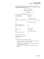
We/Wir/Nous/Wij/Noi:
Mettler-Toledo, Inc.
1150 Dearborn Drive
Worthington, Ohio 43085
USA
declare under our sole responsibility that the product,
erklären, in alleiniger Verantwortung, daß dieses Produkt,
déclarons sous notre seule responsabilité que le produit,
declaramos, bajo nuestra sola responsabilidad, que el producto,
verklaren onder onze verantwoordelijkheid, dat het product,
dichiariamo sotto nostra unica responsabilitá, che il prodotto,
Model/Type:
Jaguar and JagXtreme
to which this declaration relates is in conformity with the following standard(s) or other normative document(s).
auf das sich diese Erklärung bezieht, mitder/den folgenden Norm(en) oder Richtlinie(n) übereinstimmt.
Auquel se réfère cette déclaration est conforme à la (aux) norme(s) ou au(x) document(s) normatif(s).
Al que se refiere esta declaración es conforme a la(s) norma(s) u otro(s) documento(s) normativo(s).
Waarnaar deze verklaring verwijst, aan de volende norm(en) of richtlijn(en) beantwoordt.
A cui si riferisce questa dichiarazione è conforme alla/e sequente/i norma/e o documento/i normativo/i.
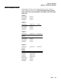
in combination with a weighing platform produced by Mettler-Toledo is in conformity with the following directives and standards.
Council directive on the harmonization of the laws of the Member states:
standards:
relating to non-automatic weighing instruments (90/384/EEC) amended by
directive (93/68/EEC)
EN 45501
relating to electromagnetic compatibility (89/336/EEC) amended by directive
(93/68/EEC; 92/31/EEC)
EN 55022-1
relating to electrical equipment designed for use within certain voltage limits
(73/23/EEC amended by directive (93/68/EEC)
EN 60950
Worthington, Ohio USA,
May, 2000
Darrell Flocken, Manager - Weights & Measures
Office of Weights and Measures
Original issue:
Revised:
July, 1995
October, 1996
May, 2000
added compliance to Low Voltage Directive
added JagXtreme
Mettler-Toledo, Inc.
INTRODUCTION
This publication is provided solely as a guide for individuals who have received Technical Training in
servicing the METTLER TOLEDO product.
Information regarding METTLER TOLEDO Technical Training may be obtained by writing to:
METTLER TOLEDO
1900 Polaris Parkway
Columbus, Ohio USA 43240
Phone (US and Canada): 614-438-4511
Phone (International): 614-438-4888
FCC Notice
This device complies with Part 15 of the FCC Rules and the Radio Interference Requirements of the
Canadian Department of Communications. Operation is subject to the following conditions: (1) this device
may not cause harmful interference, and (2) this device must accept any interference received, including
interference that may cause undesired operation.
This equipment has been tested and found to comply with the limits for a Class A digital device, pursuant
to Part 15 of FCC Rules. These limits are designed to provide reasonable protection against harmful
interference when the equipment is operated in a commercial environment. This equipment generates,
uses, and can radiate radio frequency energy and, if not installed and used in accordance with the
instruction manual, may cause harmful interference to radio communications. Operation of this equipment
in a residential area is likely to cause harmful interference in which case the user will be required to correct
the interference at his or her own expense.
ORDERING INFORMATION
It is most important that the correct part number is used when ordering parts. Parts orders are machine
processed, using only the part number and quantity as shown on the order. Orders are not edited to determine
if the part number and description agree.
COPYRIGHT
®
®
METTLER TOLEDO and JAGUAR are registered trademarks of Mettler-Toledo, Inc. JAGXTREME is a
trademark of Mettler-Toledo, Inc.
®
Allen-Bradley is a trademark of Allen-Bradley Company, Inc.
ARCnet™ is a trademark of Novell, Inc.
IPX™ is a trademark of Microsoft Corporation
All other brand or product names are trademarks or registered trademarks of their respective companies.
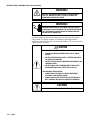
PRECAUTIONS
READ this manual BEFORE
operating or servicing this
equipment.
WARNING
DISCONNECT ALL POWER TO THIS UNIT BEFORE
INSTALLING, SERVICING, CLEANING, OR REMOVING THE
FUSE. FAILURE TO DO SO COULD RESULT IN BODILY
HARM AND/OR PROPERTY DAMAGE.
FOLLOW these instructions
carefully.
SAVE this manual for future
reference.
DO NOT allow untrained
personnel to operate, clean,
inspect, maintain, service, or
tamper with this equipment.
ALWAYS DISCONNECT this
equipment from the power
source before cleaning or
performing maintenance.
CALL METTLER TOLEDO for parts,
information, and service.
CAUTION
OBSERVE PRECAUTIONS FOR HANDLING
ELECTROSTATIC SENSITIVE DEVICES.
WARNING
ONLY PERMIT QUALIFIED PERSONNEL TO SERVICE THIS
EQUIPMENT. EXERCISE CARE WHEN MAKING CHECKS,
TESTS AND ADJUSTMENTS THAT MUST BE MADE WITH
POWER ON. FAILING TO OBSERVE THESE PRECAUTIONS
CAN RESULT IN BODILY HARM.
WARNING
FOR CONTINUED PROTECTION AGAINST SHOCK
HAZARD, CONNECT TO PROPERLY GROUNDED OUTLET
ONLY. DO NOT REMOVE THE GROUND PRONG.
CONTENTS
1
Introduction........................................................................................................................ 1-1
Model Identification............................................................................................................ 1-1
Accessories .............................................................................................................. 1-2
Specifications..................................................................................................................... 1-5
Display and Keypad .................................................................................................. 1-6
Physical Dimensions ................................................................................................. 1-7
Custom Applications................................................................................................ 1-11
Power Requirements................................................................................................ 1-11
Controller PCB ........................................................................................................ 1-12
Temperature and Humidity ....................................................................................... 1-12
Environmental Protection.......................................................................................... 1-12
Standards Compliance ...................................................................................................... 1-13
UL and cUL Listing .................................................................................................. 1-13
Weights and Measures Approval ............................................................................... 1-13
CE Conformity......................................................................................................... 1-13
Conducted and Radiated Emissions (RFI) .................................................................. 1-13
Radio Frequency Interference Susceptibility ................................................................. 1-14
AC Power Line Voltage Variation................................................................................ 1-14
2
Installation......................................................................................................................... 2-1
Unpacking and Inspection ................................................................................................... 2-1
Installing the General Purpose Model .................................................................................. 2-2
Installing the Panel Mount Model ........................................................................................ 2-3
Installing the Harsh Environment Enclosure.......................................................................... 2-4
Opening the Enclosure ............................................................................................... 2-4
Mounting the Enclosure.............................................................................................. 2-5
Electrical Connections ........................................................................................................ 2-5
Connect the Load Cell ................................................................................................ 2-5
Connect the Power Cable ......................................................................................... 2-13
Serial Port Connections— Controller PCB ................................................................... 2-15
Discrete Wiring ....................................................................................................... 2-18
Optional Multifunction I/O PCB Serial and Discrete Connections..................................... 2-19
Keyboard and Ethernet Connections ................................................................................... 2-20
JAGXTREME Terminal Jumper and Switch Settings ............................................................. 2-21
Controller ............................................................................................................... 2-21
Analog Load Cell..................................................................................................... 2-22
Single Channel Analog Load Cell............................................................................... 2-23
Dual Channel Analog Load Cell................................................................................. 2-24
Allen-Bradley RIO PCB ............................................................................................. 2-24
POWERCELL PCB.................................................................................................... 2-25
MMR (IDNET) PCB .................................................................................................. 2-26
Multifunction I/O PCB............................................................................................... 2-27
Installing Options ............................................................................................................. 2-27
Apply Power..................................................................................................................... 2-28
Power-up Sequence .......................................................................................................... 2-29
Scale Build Determination................................................................................................. 2-29
Minimum Increment Size for Bench and Portable Single DLC Scale Bases ...................... 2-29
Minimum Increment Size For Optional Analog Scale Input............................................. 2-29
Sample Calculation ................................................................................................. 2-31
Seal the Enclosure - Weights and Measures Applications .................................................... 2-31
Panel Mount Enclosure ............................................................................................ 2-31
General Purpose Enclosure....................................................................................... 2-32
Harsh Environment Enclosure ................................................................................... 2-32
3
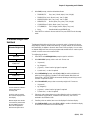
Programming and Calibration.............................................................................................. 3-1
General Information............................................................................................................ 3-1
Style Conventions...................................................................................................... 3-1
Front Panel Display ................................................................................................... 3-1
Key Functions........................................................................................................... 3-2
Accessing Setup........................................................................................................ 3-2
Navigating ............................................................................................................... 3-3
Audible Messages ..................................................................................................... 3-3
Reset to Factory ........................................................................................................ 3-4
Configuring JAGXTREME Terminals With Multiple Scales and a Summing Scale ................ 3-4
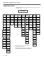
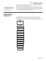
Program Block Overview ..................................................................................................... 3-6
Scale Interface Program Block............................................................................................. 3-7
1. Market Sub-block .................................................................................................. 3-8
2. Scale Type Sub-block ............................................................................................ 3-8
3. Calibration Unit Sub-block .................................................................................... 3-10
4. Capacity Sub-block ............................................................................................. 3-10
5. Increment Size Sub-block ..................................................................................... 3-11
6. Shift Adjustment Sub-block ................................................................................... 3-12
7. Linearity Correction Sub-block............................................................................... 3-12
8. Calibration Sub-block .......................................................................................... 3-12
9. Zero Adjustment Sub-block ................................................................................... 3-13
10. Span Adjustment Sub-block................................................................................ 3-14
11. Add in Sum ...................................................................................................... 3-14
12. Gravity Adjustment Sub-block ............................................................................. 3-14
13. Reset to Factory Sub-block ................................................................................. 3-14
Service Mode for MMR (IDNET) Bases ............................................................................... 3-15
NATION Program Sub-block...................................................................................... 3-15
RESET Program Sub-block ....................................................................................... 3-15
SCALE PARAMETERS Program Sub-block ................................................................... 3-16
LINEARITY Program Sub-block .................................................................................. 3-16
CALIBRATION Program Sub-block.............................................................................. 3-17
SAVE PARAMETERS Program Sub-block ..................................................................... 3-17
RETURN Program Sub-block..................................................................................... 3-17
Application Environment Program Block ............................................................................. 3-18
1. Character Set Sub-block ....................................................................................... 3-19
2. Language Sub-block............................................................................................ 3-19
3. Keyboard Type Sub-block..................................................................................... 3-19
4. Scale ID Sub-block .............................................................................................. 3-20
5. Time and Date Sub-block ..................................................................................... 3-20
6. Alternate Weight Units Sub-block ........................................................................... 3-21
7. Power Up Operation Sub-block ............................................................................. 3-23
8. Tare Operation Sub-block ..................................................................................... 3-23
9a. Zero Operation Sub-block ................................................................................... 3-25
9b. Zero Operation Sub-block for MMR (IDNET) Bases................................................ 3-26
10a. Stability Detect Sub-block ................................................................................. 3-26
10b. Stability Detect Sub-block for MMR (IDNET) Bases............................................... 3-27
11. Beeper Operation Sub-block ............................................................................... 3-27
12. Inhibit Memory Sub-Block .................................................................................. 3-27
13. Application Type Sub-block ................................................................................ 3-28
14. Vibration Rejection Sub-block ............................................................................. 3-28
14a. Vibration Rejection Sub-block for MMR ............................................................... 3-30
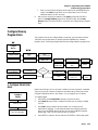
Serial Interface Program Block .......................................................................................... 3-31
1. Configure Port Sub-block...................................................................................... 3-32
2. Configure Template Sub-Block .............................................................................. 3-37
Configure Discrete Program Block ..................................................................................... 3-41
1. Discrete Inputs Sub-block..................................................................................... 3-42
2. Discrete Outputs Sub-block................................................................................... 3-43
3. Assign Setpoints Sub-block .................................................................................. 3-44
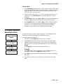
Configure Memory Program Block...................................................................................... 3-45
1. Configure Literals Sub-block ................................................................................. 3-45
2. Configure Prompts Sub-block ............................................................................... 3-46
3. Configure Consecutive Numbering Sub-block.......................................................... 3-47
Configure JagBASIC Program Block ................................................................................... 3-48
1. Keyboard Sub-block ............................................................................................ 3-48
2. Display Sub-block ............................................................................................... 3-49
3. Auto Start Sub-block ............................................................................................ 3-49
4. Manual Start Sub-block........................................................................................ 3-49
5. Send RAM Files Sub-block.................................................................................... 3-50
6. Initialize RAM Disk Sub-block................................................................................ 3-50
7. Password Maintenance Sub-block......................................................................... 3-50
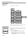
Configure Network Program Block...................................................................................... 3-51
Network Overview............................................................................................................. 3-52
General Networking Considerations ................................................................................... 3-53
IP addresses .......................................................................................................... 3-53
Clustering JAGXTREME Terminals...................................................................................... 3-54
1. Ethernet ............................................................................................................. 3-62
2. Modem .............................................................................................................. 3-63
3. Name-Password ................................................................................................. 3-63
4. PPP .................................................................................................................. 3-63
5. Cluster IP ........................................................................................................... 3-64
6. PC Data Access .................................................................................................. 3-64
7. Email................................................................................................................. 3-64
8. Web Server......................................................................................................... 3-65
9. FTP Server.......................................................................................................... 3-65
10. PLC SP Control Sub-block .................................................................................. 3-65
Diagnostics Program Block................................................................................................ 3-66
1. Memory Test Sub-block........................................................................................ 3-67
2. Display Test Sub-block ........................................................................................ 3-67
3. Keyboard Test Sub-block...................................................................................... 3-67
4. Scale Test Sub-block ........................................................................................... 3-68
5. Serial Test Sub-block ........................................................................................... 3-71
6. Parallel I/O Test Sub-block ................................................................................... 3-72
7. Network Test Sub-block........................................................................................ 3-73
8. Ethernet Send BRAM Sub-block ............................................................................. 3-73
9. Zmodem Send BRAM Sub-block............................................................................ 3-74
10. Print Setup Sub-block ........................................................................................ 3-74
11. Reset to Factory Sub-block ................................................................................. 3-75
Options Program Block...................................................................................................... 3-76
Maintenance .................................................................................................................... 3-77
1. Calibration Management ...................................................................................... 3-78
2. Calib Chk Parms................................................................................................. 3-79
3. Calib Mon Parms ................................................................................................ 3-80
Predictive Failure (Only for RAAD Box and POWERCELL Platforms) ............................... 3-82
Calibrate Check....................................................................................................... 3-83
Maintenance Reports ............................................................................................... 3-84
Network Stats ......................................................................................................... 3-84
Reset to Factory ...................................................................................................... 3-84
4
Programming and Calibration Using the Web Server............................................................. 4-1
System Requirements ......................................................................................................... 4-1
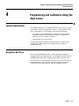
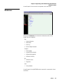
Navigation Bar Menu .......................................................................................................... 4-1
Home ...................................................................................................................... 4-2
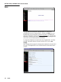
Scale ....................................................................................................................... 4-3
Application ............................................................................................................... 4-3
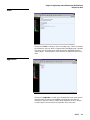
Terminal .................................................................................................................. 4-4
Communication ........................................................................................................ 4-4
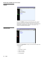
Maintenance............................................................................................................. 4-5
Documentation ......................................................................................................... 4-6
Help ........................................................................................................................ 4-6
5
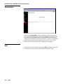
Installing and Launching JagXFILES ..................................................................................... 5-1
Installing JagXFILES ........................................................................................................... 5-1
Browser and JAGXTREME Setup........................................................................................... 5-1
Operating JagXFILES........................................................................................................... 5-1
Menu Items........................................................................................................................ 5-2
Open ....................................................................................................................... 5-2
Save........................................................................................................................ 5-2
Restore .................................................................................................................... 5-2
Backup .................................................................................................................... 5-2
All Other Menu Items.................................................................................................. 5-2
6
JAGXTREME Terminal Operations......................................................................................... 6-1
Overview............................................................................................................................ 6-1
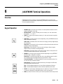
Keypad Operation ............................................................................................................... 6-1
Alphabetic and Special Character Entry ........................................................................ 6-2
Using a PC Keyboard ................................................................................................ 6-2
Normal Operating Mode ...................................................................................................... 6-3
Operator Functions.............................................................................................................. 6-3
Zero the Scale........................................................................................................... 6-3
Tare Operations ........................................................................................................ 6-4
Print Operations ........................................................................................................ 6-6
MEMORY Key Operations ........................................................................................... 6-7
FUNCTION Key Operations.......................................................................................... 6-9
Scale Selection........................................................................................................ 6-10
7
Service and Maintenance .................................................................................................... 7-1
Tools and Supplies ............................................................................................................. 7-1
Cleaning and Regular Maintenance...................................................................................... 7-1
Troubleshooting.................................................................................................................. 7-1
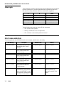
Status Lights............................................................................................................. 7-2
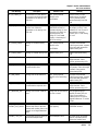
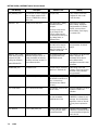
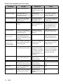
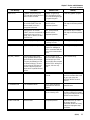
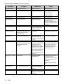
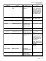
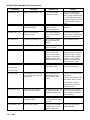
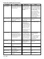
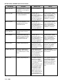
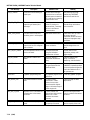
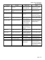
Error Codes and Actions...................................................................................................... 7-2
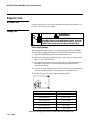
Diagnostic Tests ............................................................................................................... 7-18
AC Power Test ........................................................................................................ 7-18
Voltage Test............................................................................................................ 7-18
Backup Battery Test ................................................................................................. 7-20
Ground Test............................................................................................................ 7-21
External Equipment Test ........................................................................................... 7-21
Internal Testing ....................................................................................................... 7-21
20 mA /RS-232 Printer Tests .................................................................................... 7-21
Replacing the Power Supply .............................................................................................. 7-22
Replacing the Battery Back-up ........................................................................................... 7-23
8
Parts and Accessories......................................................................................................... 8-1
Panel Mount Parts .............................................................................................................. 8-2
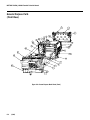
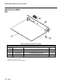
General Purpose Parts (Front View) ..................................................................................... 8-4
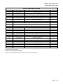
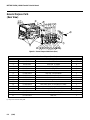
General Purpose Parts (Rear View)...................................................................................... 8-6
Harsh Environment Parts..................................................................................................... 8-7
Line Cord Assemblies ......................................................................................................... 8-9
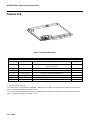
Controller PCB ................................................................................................................. 8-10
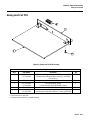
Analog Load Cell PCB ....................................................................................................... 8-11
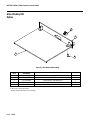
Dual Analog Load Cell PCB ............................................................................................... 8-12
Power Supply ................................................................................................................... 8-13
Allen-Bradley RIO Option................................................................................................... 8-14
PROFIBUS Option.............................................................................................................. 8-15
MODBUS Plus PCB ........................................................................................................... 8-16
Dual Analog Output Option ................................................................................................ 8-17
POWERCELL PCB .............................................................................................................. 8-18
Multifunction PCB............................................................................................................. 8-19
High Precision (IDNET) PCB .............................................................................................. 8-20
Optional Accessories ........................................................................................................ 8-21
Optional Panels ................................................................................................................ 8-22
Recommended Spare Parts ............................................................................................... 8-22
9
Appendices ........................................................................................................................ 9-1
Appendix 1: Serial Interface Reference ................................................................................ 9-1
Hardware Connections............................................................................................... 9-2
Output Modes and Formats ........................................................................................ 9-3
Standard Status Bytes A, B, and C............................................................................... 9-4
4-Setpoint Status Bytes A, B, and C ............................................................................. 9-5
Multi Cont 1 ............................................................................................................. 9-7
Multi Cont 2 ............................................................................................................. 9-8
Default Template Formats......................................................................................... 9-10
Input Modes ........................................................................................................... 9-13
ASCII Characters ..................................................................................................... 9-18
Appendix 2: Discrete I/O Reference.................................................................................... 9-22
Inputs .................................................................................................................... 9-22
Outputs.................................................................................................................. 9-23
Appendix 3: Network Reference......................................................................................... 9-24
Keyboard/Display Sharing ........................................................................................ 9-24
Redirecting Serial Output .......................................................................................... 9-25
A-B RIO / PROFIBUS / MODBUS+ Option Sharing......................................................... 9-26
Appendix 4: Loading JAGXTREME Software ........................................................................ 9-26
Flash the Software ................................................................................................... 9-26
Appendix 5: JAGXTREME Default Values ............................................................................ 9-30
Appendix 6: Gravity Factors............................................................................................... 9-37
Appendix 7: Multiple Range and Multi-Interval Operation.................................................... 9-38
Multiple Range Operation ......................................................................................... 9-38
Multi-Interval Operation ............................................................................................ 9-39
Appendix 8: Market Destination (Finish) Codes .................................................................. 9-41
Chapter 1: Introduction
Model Identification
1
Introduction
Model Identification
The JAGXTREME Internet-enabled scale terminal is designed to help companies provide
cost-effective, flexible methods of production while maximizing engineering time and
effort. It offers connectivity to all METTLER TOLEDO technologies, as well as open
connectivity to the leading industry technologies, to facilitate communication and data
exchange with companies’ control, manufacturing execution, and enterprise systems.
The JAGXTREME terminal is available with various operator interfaces and enclosure
types. Please refer to the following Factory Number Reference chart to identify the
JAGXTREME terminal with which you will be working. A detailed description of each
designation is given to help you determine the specifications for each model. A brief
description of the optional accessories appears on the next page.
If you are upgrading an existing METTLER TOLEDO JAGUAR terminal to a new
JAGXTREME terminal, refer to the instructions provided with your upgrade kit.
For users of the JAGXTREME terminal’s predecessor, METTLER TOLEDO’s JAGUAR
terminal, please pay special attention to the programming and calibration section.
Programming and calibration of the JAGXTREME terminal can be performed via the
embedded web server as well as through the front panel of the unit.
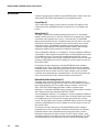
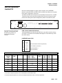
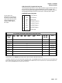
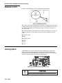
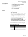
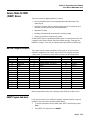
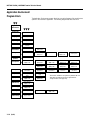
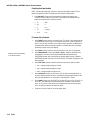
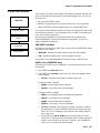
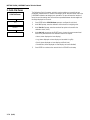
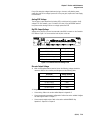
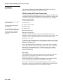
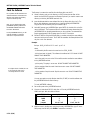
FACTORY NUMBER REFERENCE CHART
JAGXTREME TERMINAL MODEL CONFIGURATION
Example: JXPB-1600-000
JX
Terminal
JAGXTREME
Terminal
XX
Enclosure
Display
PB=Panel, Blind
PA=Panel, A/N
GA=General
Purpose A/N
HA=Harsh, A/N
X
Slot #1
Accessory
0=Cover Plate
1=Analog Scale
2=R E* Analog Scale
3=POWERCELL
4=MMR Base
7=Multifunction I/O
A=Dual Analog Scale
B=Dual R E* Analog
Scale
X
Slot #2
Accessory
0=Cover Plate
1=Analog Scale
2= R E*Analog Scale
3=POWERCELL
4=MMR Base
7=Multifunction I/O
A=Dual Analog Scale
B=Dual R E Analog
Scale
X
Slot #3
Accessory
0=Cover Plate
5=Modbus Plus
6=Allen Bradley RIO
7=Multi-function I/O
8=Dual Channel
Analog Output
9=PROFIBUS DP
X
Application
Software
0=Standard
JagBASIC
(included)
XXX
Destination
Market
000=USA
See the Market
Codes in the
Appendix for
additional
destination
codes
* RE – Reduced Excitation. JAGXTREME terminals with harsh environment enclosures
are not approved for use in hazardous areas.
(9-00)
1-1
METTLER TOLEDO JAGXTREME Terminal Technical Manual
Accessories
A number of accessories are available for the JAGXTREME terminal. Please contact your
authorized METTLER TOLEDO representative for more detailed information.
Cover Plate (0)
This thin metal plate is used to cover the opening in the back of the regular or blind
chassis panel-mount JAGXTREME terminal if an optional PCB is not installed at this
location.
Analog Scale (1)
This option is required when interfacing analog type load cells. A 15-volt excitation
voltage is used to power up to 16 350-ohm load cells from one Analog PCB. A jumper
is provided to select operation with 2 mV/V or 3 mV/V load cells. The JAGXTREME
terminal will operate with load cells of impedances other than 350 ohms or other mV/V
specifications, but the total scale resistance must not be less than 22 ohms. A quiet
analog signal section, combined with a proprietary analog-to-digital converter and
coprocessor implementing METTLER TOLEDO proprietary TraxDSP filters, provides
weighing and vibration rejection performance unequaled in the industry.
The zero temperature coefficient is 0.15 µV/degree C. The span temperature coefficient is
6 ppm/degree C. When using the analog scale option, the display update rate is limited
to 10 updates per second. The actual A/D conversion rate exceeds 300 cycles per
second. This high-speed process allows the JAGXTREME terminal to filter out noise while
providing a weight update rate of up to 50 updates per second for setpoint control and
other scale functions.
Each analog scale option board has a removable EEPROM that stores calibration
parameters for the scale. If an EEPROM is transferred to another board, all calibration
parameters transfer. A detachable seven-position terminal strip is used to terminate the
analog load cell cable on the rear of the PCB. Signal, excitation, sense, and shield
connections are provided with easy-to-read descriptions. Two LEDs are visible through
holes in the rear panel of the PCB to indicate the status of the Analog PCB.
Reduced Excitation Analog Scale (2)
This option, when used with a protective load cell barrier, allows operation of the
JAGXTREME terminal with analog load cells located in an area classified as hazardous
by the National Electrical Code. The excitation voltage is lowered to 5 volts for this
option. A METTLER TOLEDO Reduced Excitation module is required for these
applications. The standard JAGXTREME terminal cannot be located inside the hazardous
area. Purged enclosures are available from METTLER TOLEDO.
The zero temperature coefficient is 0.15 µV/degree C. The span temperature coefficient is
6 ppm/degree C. When using the analog scale option, the display update rate is limited
to 10 updates per second. The actual A/D conversion rate exceeds 300 cycles per
second. This high-speed process allows the JAGXTREME terminal to filter out noise while
providing a weight update rate of up to 50 updates per second for setpoint control and
other scale functions.
Each analog scale option board has a removable EEPROM that stores calibration
parameters for the scale. If an EEPROM is transferred to another board, all calibration
parameters transfer as well. A detachable seven-position terminal strip is used to
terminate the analog load cell cable on the rear of the PCB. Signal, excitation, sense,
and shield connections are provided, each with an easy-to-read description. Two LEDs
are visible through holes in the rear panel of the PCB to indicate its operating status.
1-2
(9/00)
Chapter 1: Introduction
Model Identification
POWERCELL (3)
The POWERCELL interface must be used when the JAGXTREME terminal is used with a
METTLER TOLEDO load cell. The POWERCELL I/O option supports up to 24 cells (an
external power supply is needed for scales with more than 14 cells). The POWERCELL
I/O PCB can be used with the METTLER TOLEDO Hazardous Area Barrier Box. Please
contact your METTLER TOLEDO representative for more information about applications in
hazardous environments.
MMR (IDNET) (4)
The IDNET Interface Module allows you to interface a METTLER TOLEDO Multi-Range
base or lab balance with IDNET option with the JAGXTREME terminal. When utilizing this
interface, the JAGXTREME terminal acts as a “front end” for the base. Setup and
calibration of the base is identical to the procedure used by the ID family of indicators.
Scale related information is stored in the scale base as well as the JAGXTREME terminal,
allowing its access by external devices such as a PLC.
Modbus Plus (5)
The Modbus Plus interface enables the terminal to directly interface with Modbus Plus
devices such as PLCs manufactured by MODICON. The JAGXTREME terminal interface
acts as a single Modbus Plus node, which can support up to four scales, and has been
fully certified by the Modicon Test Center.
Allen-Bradley RIO (6)
This option allows the JAGXTREME terminal to exchange data with an Allen-Bradley PLC
like a remote 1771 module on the Allen-Bradley remote I/O. A direct connection to an
Allen-Bradley controller is possible via this “blue hose” connection. If the terminal has
two or more scales installed, all share the same RIO option board. If multiple terminals
are combined in a “cluster” using Ethernet, up to four scales can share the RIO option.
Each scale requires one-quarter rack of RIO address space. JAGXTREME terminals
support quarter rack addressing.
JAGXTREME terminals support discrete and block transfer modes of data interface. Both
are bi-directional. Discrete mode is used for data, status, and command exchange.
Block transfer allows more extensive data exchange and allows the PLC to write
messages to the terminal’s lower alphanumeric display. Connection to the RIO option is
made via a detachable three-position terminal strip on the rear of the RIO option.
Multifunction I/O (7)
The Multifunction PCB option expands the number of serial and discrete input and output
ports supported by the JAGXTREME terminal. The Multifunction PCB adds two serial
ports. COM3 can be used for RS-232 communications. COM4 can be used for RS-232
or RS-422/RS-485 communications. COM4 can be used for a single DigiTOL or
UltraRes understructure interface. The Multifunction PCB adds eight programmable
discrete inputs (PAR 3). Eight programmable discrete outputs (PAR 4). PAR 3 and PAR
4 assignments are user-configurable.
Dual Channel Analog Output (8)
The Analog Output Module provides two channels of analog output, one for each of up
to two scales connected to the terminal. The channels may be selected to provide either
a 0 to 10 V or a 4 to 20 mA analog output signal. The output is the result of a 16-bit
digital to analog conversion.
(9-00)
1-3
METTLER TOLEDO JAGXTREME Terminal Technical Manual
PROFIBUS Interface (9)
The JAGXTREME terminal with the PROFIBUS Interface Module is a fully L2-DP compliant
device which can be used with a wide range of PROFIBUS compatible devices. This
module provides the process control engineer with the ability to access weight
information, status of the scale, and to download a setpoint or tare weight. The Profibus
option has been fully certified by the Siemens Profibus Test Center.
Dual Analog Scale (A)
An analog scale option is required when interfacing analog type load cells. A 15-volt
excitation voltage is used to power up to 16 350-ohm load cells from one analog
channel. The dual channel card can support a maximum of 20 load cells. A jumper is
provided to select operation with either 2mV/V or 3mV/V load cells. The JAGXTREME
terminal will operate with load cells of impedances other than 350 ohms or other mV/V
specifications, but the total scale resistance must not be less than 22 ohms.
A quiet analog signal section, combined with a proprietary analog-to-digital converter
and co-processor that use METTLER TOLEDO’s proprietary TraxDSP filters, provides
weighing and vibration rejection performance unequaled in the industry. The zero
temperature coefficient is 0.15 uV/degree C. The span temperature coefficient is 6
ppm/degree C.
When using the analog scale option, the display update rate is limited to 10 updates per
second. The actual A/D conversion rate exceeds 300 cycles per second. The high-speed
process allows the terminal to filter out noise while providing a weight update rate up to
50 updates per second for setpoint control and other functions.
The dual channel analog scale option board has a removable EEPROM for each scale
channel that stores calibration parameters for that scale channel. If an EEPROM is
transferred to another board, all calibration parameters transfer as well.
A detachable seven-position terminal strip is used to terminate each analog load cell
cable on the rear of the PCB. Signal, excitation, sense, and shield connections are
provided with easy-to-read descriptions. Two LEDs are visible through holes in the rear
panel of the PCB to indicate the status of the Analog PCB. The JAGXTREME terminal
supports up to two dual analog scale cards.
Reduced Excitation Dual Analog Scale (B)
The analog scale option is used with a protective load cell barrier to permit operation of
the JAGXTREME terminal with analog load cells located in an area classified as
hazardous by the National Electrical Code. The excitation voltage is lowered to 5 volts
for this option. A METTLER TOLEDO Reduced Excitation module is required for these
applications. The standard JAGXTREME terminal cannot be located inside the hazardous
area as is. Purged enclosures are available from METTLER TOLEDO if the terminal must
be located inside the hazardous area. Note: The Reduced Excitation module can only
support up to 12 analog load cells or a total resistance of 58 ohms.
Jumpers are provided to select operation with 2mV/V or 3mV/V load cells. The terminal
will operate with load cells of impedances other than 350 ohms or other mV/V
specifications, but the total scale resistance must not be less than 22 ohms.
The zero temperature coefficient is 0.15 uV/degree C. The span temperature coefficient is
6 ppm/degree C. When using the analog scale option, the display update rate is limited
to 10 updates per second. The actual A/D conversion rate exceeds 300 cycles per
second. The high-speed process allows the JAGXTREME terminal to filter out noise and
still provide a weight update rate up to 50 updates per second for setpoint control and
other scale functions.
1-4
(9/00)
Chapter 1: Introduction
Specifications
The dual channel analog scale option board has a removable EEPROM for each scale
channel that stores calibration parameters for that scale channel. If an EEPROM is
transferred to another board, all calibration parameters transfer as well.
A detachable seven-position terminal strip is used to terminate each analog load cell
cable on the rear of this PCB. Signal, excitation, sense, and shield connections are
provided, each with an easy-to-read description. Two LEDs are visible through holes in
the rear panel of this PCB to indicate the status of the Analog PCB. The JAGXTREME
terminal will support one or two Reduced Excitation dual analog scale cards.
Specifications
Model
Dimensions
Construction
Mounting Options
Degree of
Protection
Ethernet
Connection
Attachable
Platforms
Display
Keypad
Interfaces
A/D Rate
Digital
Input/Output
Maintenance
Monitoring
Signal Processing
Power
Requirements
Setup
Scripting
Language
Operating
Temperature
Storage
Temperature
Options
Approvals
General Purpose
12.45 in (25 cm) wide x 7.86
in (20 cm) high x 10.6 in (27
cm) deep
Column, desktop
NEMA 4
Panel Mount
10.05 in (25.5 cm) x 5.6 in
(14 cm) at front of terminal
9.5 in (24 cm) x 4.91 in (12.5
cm) at the rear
8.03 in (21 cm) deep
Aluminum
Panel
NEMA 4 (front panel)
Panel Mount – Blind Chassis
10.75 in (27 cm) x 4.31 in
(10.9 cm) at base
10.25 in (26 cm) x 3.91 in
(10 cm) c-c mounting
9.5 in (24.1 cm) x 5.00 in (13
cm) chassis
Harsh Environment
12.62 in (32.1 cm) x 8.03 in
(21 cm) x 9.3 in (23.6 cm)
Blind panel
NEMA 1
Stainless steel
Wall, column
NEMA 4X (IP65)
10BASE-T. Uses crossover cable from RJ-45 Ethernet port on the back of the JAGXTREME terminal to a PC (point to-point connection) or
standard cable to connect to other equipment through a hub.
4 analog or 4 POWERCELL or 2 High Precision or 2 DigiTOL
Two vacuum fluorescent displays. Upper display: 7 segment 0.5" (13 mm); lower display: 16-character, 5 x 7 dot matrix display 0.25"
(6 mm)
4 x 5 matrix tactile-feel keypad with 0-9, letters A-Z, and function keys
Ethernet, serial, discrete, PLC, analog, network
>300 per second
Maximum 12 in/12 out
TraxEMT Embedded Maintenance Technician system for self-diagnosis and predictive failure analysis
TraxDSP three-stage filtering
85 to 264 VAC with a line frequency of 47 to 63 Hz
Via embedded web server, with the front keypad or using the JagXFILES tool box.
JagBASIC (standard)
14° F to 113° F (-10° C to 45° C) at 10% to 95% relative humidity, non-condensing
40° F to 140° F (-40° C to 60° C) at 10% to 95% relative humidity, non-condensing
Analog, Dual Analog, Analog Reduced Excitation Dual Analog Reduced Excitation Dual Analog Output, Modbus Plus, Profibus, A-B RIO,
Multifunction I/O, IDNet, POWERCELL, PCJagBASIC EDITOR
CE Conformity
90/384/EU – Non-automatic Balances and Scales
EN45501:1992 – Adopted European Standard
Weights and Measures (US)
Class III or IIIL devices
NTEP Certificate of Conformance No. 94-096
Weights and Measures (Australia)
Class III and IIIL non-automatic weighing instruments as defined in the National Standards Commission, Document 100
(9-00)
1-5
METTLER TOLEDO JAGXTREME Terminal Technical Manual
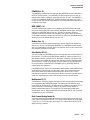
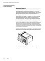
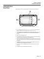
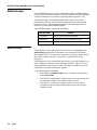
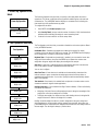
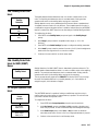
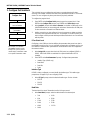
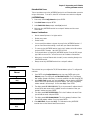
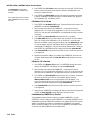
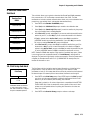
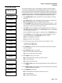
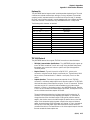
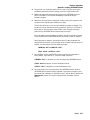
Display and Keypad
Alpha-numeric Display (xA)
The front of the JAGXTREME terminal contains two vacuum fluorescent displays and a 4
× 5 matrix tactile feel keypad in a diecast, zinc-aluminum alloy front housing.
The upper weight display is a seven-digit, seven-segment 0.5 in. (13 mm) high
vacuum fluorescent numeric display used to indicate weight values. Each of the seven
digits has a decimal point/comma and an annunciator associated with it. The
annunciators are used to indicate gross or net weights, a preset tare value, pound or
kilogram weights, the center of zero, and motion.
The lower display is a 16-character, 5×7 dot matrix, 0.25 in. (6 mm) high vacuum
fluorescent alphanumeric display. Each character has a period/comma and an
annunciator associated with it. This display is used to indicate tare, alternate weight
units, operator prompting, errors and other messages. The first 10 annunciators are
used to indicate which terminal number (1 through 6) and internal scale (A-D) are
currently displayed. The remainder indicates summation and weighing range.
The lens on both the general purpose and panel mount model lens are polycarbonate
with hardcoating. The harsh environment model lens is polyester with hardcoating.
The keypad consists of a tactile-feel membrane switch covered with a polyester overlay.
It is designed to give the operator positive feedback when pressing a key. Audible beeps
can be enabled to verify key depressions.
The keypad contains the numbers 0 -9 and the letters A - Z. Other function keys include
Escape, Memory, Tare, Select, Clear, space, decimal point, Zero, Enter, and Function.
These keys allow access to operator prompting, setup, and many other scale functions.
1-a: Display and keypad on panel-mount version of the JAGXTREME
1-6
(9/00)
Chapter 1: Introduction
Specifications
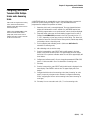
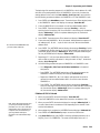
Physical Dimensions
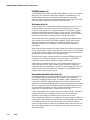
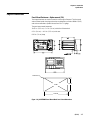
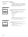
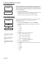
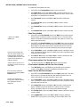
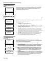
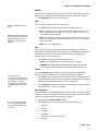
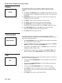
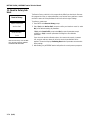
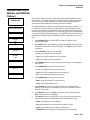
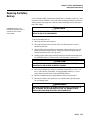
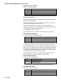
Panel Mount Enclosure— Alpha-numeric (PA)
Two integral brackets are used to mount this unit through a flat panel. The front panel
and associated panel clamping mechanism are designed to provide a NEMA 4 (IP65)
seal and accommodate a panel thickness from 16 to 11 gauge.
The panel-mount model measures:
10.05 in. (25.5 cm) × 5.6 in. (14 cm) at the front of the terminal
9.5 in. (24 cm) × 4.91 in. (12.5 cm) at the rear
8.03 in. (21 cm) deep
4XR 0.25±.01
OPEN
Abra
5.12±.0
9.58±.06
Figure 1-b: JAGXTREME Panel Mount Model and Cutout Dimensions
(9-00)
1-7
METTLER TOLEDO JAGXTREME Terminal Technical Manual
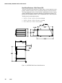
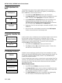
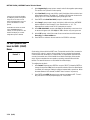
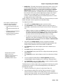
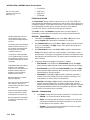
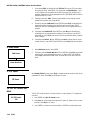
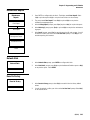
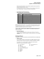
Panel Mount Enclosure— Blind Chassis (PB)
The front of the panel mount enclosure has a blank plate to cover the electronics and to
provide a method of mounting. There is no keyboard or display on the front of the unit.
This allows the terminal’s use as a “blind” terminal (installed behind a panel,) sharing
another JAGXTREME terminal’s keyboard and display via the Ethernet connection. The
terminal enclosure designed to NEMA 1 or IP30 requirements with a “blind” front panel.
The blind chassis mount model measures:
!
10.75 in. (27 cm) × 4.31 in. (10.9 cm) at the base
!
10.25 in. (26 cm) × 3.91 in. (10 cm) c-c mounting
!
9.5 in. (24.1 cm) × 5.00 in. (13 cm) chassis
Figure 1-c: JAGXTREME Blind Chassis Model Dimensions
1-8
(9/00)
Chapter 1: Introduction
Specifications
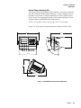
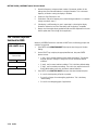
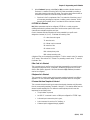
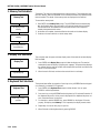
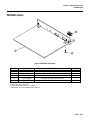
General Purpose Enclosure (GA)
This enclosure, which provides NEMA 4 (IP65) protection, is a die-cast zinc-aluminum
alloy with an aliphatic urethane powder-coated finish. The unit is designed to sit on a
flat surface or may be wall- or column-mounted with an accessory bracket kit (09170209). The rear cover contains grip bushings to seal all cables entering the enclosure.
The general-purpose JAGXTREME terminal model measures:
12.45 in. (25 cm) wide × 7.86 in. (20 cm) high x 10.6 in. (27 cm) deep
In figure 1-d, the top views show optional wall/column brackets (P/N 0917-0209).
12.45
12 4
12.31
12 3
29°
2 °
115°
°
11
10.05
10 0
39°
3 °
7.85
78
10.59
10 5
Figure 1-d: JAGXTREME General Purpose Model Dimensions
(9-00)
1-9
METTLER TOLEDO JAGXTREME Terminal Technical Manual
Harsh Environment Enclosure (HA)
The harsh environment enclosure provides NEMA 4X (IP65) protection and is intended
for applications in which the terminal is exposed to high humidity, direct washdown, or
corrosive environments. It is constructed of 304L stainless steel and meets all US FDA
and comparable European requirements.
A full 4-slot JAGXTREME terminal chassis is mounted inside the enclosure. All field
wiring enters into the unit through cable seals that maintain the washdown protection of
the enclosure. The cable seals are located at the bottom rear of the unit. Two brackets
are provided for wall mount applications. An interface adapter (0917-0233) is available
for column mount applications.
The harsh environment enclosure model measures: 12.62 in (32.1 cm) x 8.03 in (21
cm) x 9.3 in (23.6 cm)
12.62
8.25
0.50
11.62
11.12
0.84
0.56
ABC
7
JKL
4
STU
1
$#%
0
DEF
8
MNO
5
VWX
2
-/=
GHI
9
PQR
6
YZ?
3
*()
SP
FUNCTI
F
MEMO
M
SELE
S
ZER
ESC
TA
T
CLE
C
5.75
9.42
ENT
0
* Shown with wall mount brackets
(included with enclosure) installed.
Figure 1-e: Harsh Environment Model Dimensions
1-10
(9/00)
Chapter 1: Introduction
Specifications
Custom Applications
JagBASIC
JagBASIC provides for the development of easy-to-use custom applications. JagBASIC
programs reside along side the standard JAGXTREME terminal program. The JagBASIC
interpreter runs as a separate task using the terminal’s multi-tasking operating system.
This allows the custom JagBASIC program to interact with the other JAGXTREME terminal
tasks and resources using the terminal’s exclusive shared memory design. For example,
to monitor a scale gross weight, the JagBASIC program relates a BASIC variable to the
terminal shared data variable for gross weight then uses the BASIC variable as desired.
All of the shared memory in the terminal may be accessed by the JagBASIC program
using this construct.
The high level of integration permits the programmer to exploit the standard functions in
the JAGXTREME terminal, making it easier to implement solid solutions in record time.
To print a standard ticket or report, a JagBASIC program can load data into a
JAGXTREME terminal shared data variable then print by using a standard template that
is designed in the terminal setup. Rather than monitoring setpoint coincidence in the
JagBASIC program, a standard setpoint shared data variable can be loaded in the
program then monitored by an associated JAGXTREME terminal scale task.
Power Requirements
!
85 to 264 VAC with a line frequency of 47 to 63 Hz.
!
Power consumption -- 20 Watts maximum.
!
Power termination -- single three-position removable terminal strip.
!
The wire size range -- 16 to 12 AWG.
Note: The integrity of the power ground for equipment is important for both safety and
dependable operation of the JAGXTREME terminal and it’s associated scale bases. A
poor ground can result in an unsafe condition if an electrical short develops in the
equipment. A good ground connection is needed to assure extraneous electrical noise
pulses are minimized. It is important that equipment does not share power lines with
noise generating equipment like heavy load switching, motor starter circuits, RF thermal
heaters, inductive loads and the like.
To confirm ground integrity, a commercial branch circuit analyzer is recommended. This
instrument uses a high amperage pulse to check ground resistance. It measures the
voltage from the neutral wire to the ground connection and will provide an assessment
of the line loading. Instructions with the instrument give guidelines about limits that
assure good connections. Visual inspections and a query of the user will provide
information about equipment sharing the power line.
The power line for the JAGXTREME terminal must not be shared with equipment such as
motors, relays, or heaters that generate line noise. If adverse power conditions exist, a
dedicated power circuit or power line conditioner may be required.
(9-00) 1-11
METTLER TOLEDO JAGXTREME Terminal Technical Manual
Controller PCB
!
Four discrete inputs (PAR1).
!
Four discrete outputs (PAR2)(5 to 30 Volts DC).
!
The output current is 35 mA per discrete output up to 115 mA maximum total current
draw on the +5 Volts DC supply.
!
Inputs can be defined as clear (return to gross), tare, print, zero, and other keyboard
functions.
!
Outputs can be defined for coincidence setpoints or a variety of scale conditions.
!
The COM1 serial port can be either RS-232 or 20 mA current loop active transmit.
Both are available simultaneously.
!
The COM2 serial port can be either RS-232 or RS-422/RS-485. This port is also
used to support a DigiTOL or UltraRes scale interface.
!
Keyboard input is a standard 6-pin PS2 type mini DIN connection for a compatible
keyboard.
!
The Ethernet network connection is accomplished using a RJ45 connection.
!
Connections to the Controller PCB are made using four removable terminal strips.
The wire size range for these terminal strips is 23 to 16 AWG.
!
The Controller PCB stores DigiTOL scale calibration parameters in its EEPROM. If
analog load cell scale(s) are installed, the calibration parameters for each scale are
stored in the EEPROM of its Analog PCB. IDNET calibration parameters are stored in
the base. POWERCELL parameters are stored on the POWERCELL PCB.
Temperature and Humidity
! Operating temperature: 14 to 113ºF (-10 to 45ºC) at 10% to 95% humidity, noncondensing.
! Storage temperature: -40 to 140ºF (-40 to 60ºC) at 10% to 95% humidity,
noncondensing.
! The optional Analog PCB zero temperature coefficient is 0.15 µV/ºC. Span
temperature coefficient is 6 ppm/° C maximum.
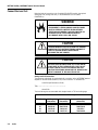
Environmental Protection
The JAGXTREME terminal is not intrinsically safe! In addition to the Reduced Excitation
Analog Scale option, a METTLER TOLEDO Hazardous Area Protection safety module is
required for JAGXTREME terminals operating with scales located in a hazardous area.
Contact your METTLER TOLEDO representative for information.
WARNING!
THE JAGXTREME TERMINAL IS NOT INTRINSICALLY SAFE! DO
NOT USE IN AREAS CLASSIFIED AS HAZARDOUS BY THE
NATIONAL ELECTRIC CODE (NEC) BECAUSE OF COMBUSTIBLE OR EXPLOSIVE ATMOSPHERES.
1-12
(9/00)
Chapter 1: Introduction
Standards Compliance
Standards Compliance
UL and cUL Listing
The JAGXTREME terminal has been tested and complies with UL 1950 and CSA 22.2
No. 950-M89. The JAGXTREME terminal carries the UL and cUL labels.
Weights and Measures
Approval
United States
The JAGXTREME terminal meets or exceeds requirements for Class III or IIIL devices.
Certificate of Conformance No. 94-096A4 was issued under the National Type
Evaluation Program of the National Conference on Weights and Measures.
Canada
The JAGXTREME terminal meets or exceeds requirements for a 10,000 division rating
and approval AM-5041 has been issued by statutory authority of the Minister of
Industry, Science and Technology of Canada.
Australia
The JAGXTREME terminal meets or exceeds the requirements for Class III and IIIL nonautomatic weighing instruments as defined in the National Standards Commission,
Document 100. The National Standards Commission has approved the JAGXTREME
terminal for use with approved and compatible platforms.
Europe
The JAGXTREME terminal was submitted for approval to The Nederlands Meetindtituut
(NMi) in the Netherlands. After evaluation, the JAGXTREME terminal was found to meet
and/or exceed the requirements for a Class III weighing instrument. EC type approval
certificate TC2618 (Revision 5) was issued by the NMi in accordance to Council
Directive 90/384/EEC.
CE Conformity
The JAGXTREME terminal conforms to the following European Union regulations:
!
90/384/EU—Non-automatic Balances and Scales
!
EN45501:1992—Adopted European Standard
!
89/336/EU—EMC Directive
!
EN55022, A 01.04.87
(9-00) 1-13
METTLER TOLEDO JAGXTREME Terminal Technical Manual
Conducted and Radiated
Emissions (RFI)
The JAGXTREME terminal meets or exceeds FCC Part 15 for conducted and radiated
emissions requirements as a Class A digital device.
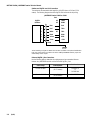
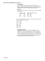
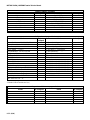
Radio Frequency
Interference Susceptibility
The JAGXTREME terminal meets US, Canadian, and European requirements for RFI
susceptibility as listed in the following table with a maximum of one display increment of
change when calibrated for recommended builds.
Radio Interference Frequency
26-1000 MHz
Field Strength
3 volts/meter
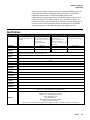
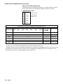
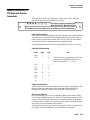
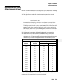
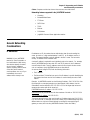
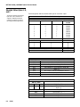
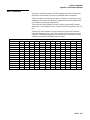
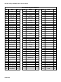
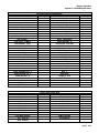
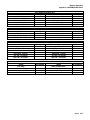
AC Power Line Voltage
Variation
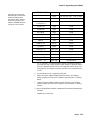
The JAGXTREME terminal meets NIST H-44, Canadian Gazette Part 1, and OIMLSP7/SP2 line voltage variation specifications as listed in the following table.
AC Power Line Voltages
Specification
Line Voltage Variation
NIST H-44
Canadian
OIML-SP7/SP2
1-14
(9/00)
AC Line Voltage
Minimum
100
108
102
187
204
Nominal
120
120
120
220
264
Maximum
130
132
132
242
264
Line Frequency in Hz
Minimum
Nominal
59.5
60
58.8
60
58.8
60
49.0
50
49.0
50
Maximum
60.5
61.2
61.2
51
51
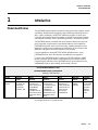
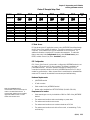
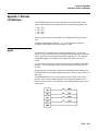
Chapter 2: Installation
Unpacking and Inspection
2
Installation
Unpacking and
Inspection
If upon delivery the shipping container for the JAGXTREME terminal appears damaged,
check for internal damage and file a freight claim with the carrier if required. If the
container is undamaged, unpack the JAGXTREME terminal from its protective package,
noting how it was packed, and inspect each component for damage. If it is necessary to
ship the terminal at any time, use the original shipping container if possible.
Package contents for all JAGXTREME terminals include:
•
JAGXTREME terminal
•
Screwdriver
•
Installation guide
•
Set of capacity labels
•
Weights and Measures sealing screws
•
Mating connectors for the I/O port
•
Cable tie wraps
•
JAGXTREME CD with documentation and ancillary software
Package contents for the panel mount and blind chassis JAGXTREME terminal include:
•
Six (6) nylon cable ties
•
2 mm Allen wrench (panel mount only)
Package contents for the harsh environment JAGXTREME terminal include:
Note: The (*) designation
before a part number indicates
that the part number may be
proceeded by a letter
designation such as A, B, C
and so on.
•
2 stainless steel wall mount brackets
•
4 stainless steel bolts for attaching the wall mount brackets
•
Hardware kit (*)15411500A
Package contents for the general purpose JAGXTREME terminal includes:
•
Hardware kit (*)15411400A
(9/00)
2-1
METTLER TOLEDO JAGXTREME Terminal Technical Manual
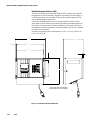
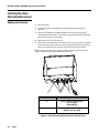
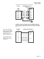
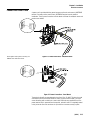
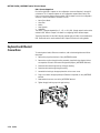
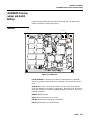
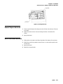
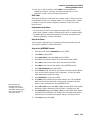
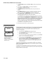
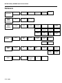
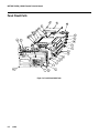
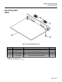
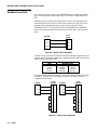
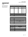
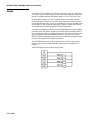
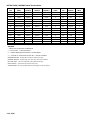
Installing the General
Purpose Model
Place the general purpose (desk top) model at the operating site.
•
Remove the four screws securing the rear access cover to the main housing
using a Phillips head screwdriver.
•
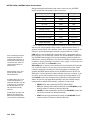
With the rear access cover removed, you are now ready to make connections
to the unit. Figure 2-a describes the recommended wiring connections.
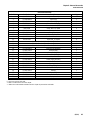
C
D
Reference Letter
Suggested Cable
A
Serial I/O Cables (Except DigiTOL)
PLC I/F Cabling
Ethernet Wiring
B
Analog Load Cell Cabling
DigiTOL Load Cell Cabling
C
Ethernet Cable
D
QWERTY Keyboard
Figure 2-a: General Purpose Wiring Connections and Cable Chart
To connect the unit:
Be careful to select an opening
close to the terminal block you
are wiring to keep the wiring
neat and easy to connect.
1. Pass the cables that enter the general-purpose enclosure through an appropriately
sized cable grip before connecting the wires.
2. Tighten the cable grip to provide a water-tight seal around the cable after resecuring the back cover. This allows any internal cable slack to be received through
the cable grip.
3. Continue to the section entitled Electrical Connections.
2-2
(9/00)
Chapter 2: Installation
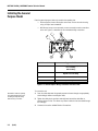
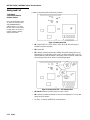
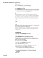
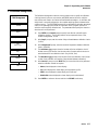
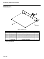
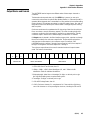
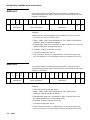
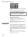
Installing the Panel Mount Model
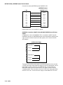
Installing the Panel
Mount Model
Refer to Figure 2-b and the instructions below to install the panel mount terminal.
B
A
A
Figure 2-b: Panel Mount Installation Diagram
1. Cut an opening 9.58 in. (24.33 cm) × 5.12 in. (13.0 cm) to accommodate the
terminal. The tolerance for the panel cutout is ±0.06 in. (0.15 cm).
2. Using the Allen wrench included with the unit, remove the four retaining set screws
(A) located at the rear of the enclosure in the top and bottom mounting plate
grooves.
3. Remove both mounting plates (B).
4. Insert the terminal through the panel opening from the front until it is flush against
the panel. Confirm that the terminal is installed right side up.
5. Slide the top and bottom mounting plates back in the grooves and push them flush
against the panel from the back. The flared end of the plate should contact the back
of the panel.
6. Holding the unit in place, replace the four set screws and tighten until the unit is
secured and the front panel gasket is compressed.
7. Inspect the front of the JAGXTREME terminal for a good seal to the front of the
enclosure.
8. Continue to the section entitled Electrical Connections.
(9/00)
2-3
METTLER TOLEDO JAGXTREME Terminal Technical Manual
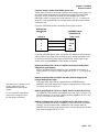
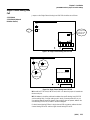
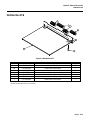
Installing the Harsh
Environment Enclosure
Opening the Enclosure
1. Disconnect power.
2. Locate the two slots on the bottom lip of the front of the harsh environment
enclosure.
3. Gently insert the blade of a slotted screwdriver into one of the slots and press
inward (toward the enclosure). This releases a pressure tab that allows the access
panel of the enclosure to open slightly.
4. Repeat steps 2 and 3 for the other slot.
5. Remove the access panel away from the enclosure. The access panel is connected
to the Controller PCB by a cable and cannot be removed without disconnecting the
cable. You should be able to access the unit with the front panel connected.
With the access cover removed, you are now ready to make connections to the unit.
Figure 2-c describes the recommended wiring connections.
A
B
A
Reference Letter
Suggested Cable
A
Serial I/O Cables (Except DigiTOL)
PLC I/F Cabling
Ethernet Wiring
B
Analog Load Cell Cabling
DigiTOL Load Cell Cabling
Figure 2-c: Harsh Environment Wiring Connections and Cable Chart
2-4
(9/00)
Chapter 2: Installation
Mounting the Enclosure
1. Locate the two mounting brackets that came in the JAGXTREME terminal package.
2. Mount the brackets using the four stainless steel screws supplied with the unit. Refer
to Figure 2-d and note the correct positioning of the brackets. The slotted holes
must protrude beyond the enclosure and the bracket tabs must point toward the
front as shown.
* Shown with wall mount brackets
(included with enclosure) installed.
Figure 2-d: Wall Mount (Harsh Environment) Brackets
3. Tighten the brackets to the back of the enclosure (torque 25 inch pounds).
4. Using the dimensions given in Figure 2-d, prepare the mounting surface to accept
the enclosure. The mounting surface and brackets must be able to support a total of
45 lb (20 kg).
5. Place the enclosure on the mounting surface and secure with appropriate fasteners.
Electrical Connections
WARNING!
PERMIT QUALIFIED PERSONNEL ONLY TO SERVICE THIS
EQUIPMENT. DISCONNECT ALL AC POWER TO THIS UNIT
BEFORE SERVICING OR REMOVING THE FUSE. EXERCISE
CARE WHEN MAKING CHECKS, TESTS, AND ADJUSTMENTS
THAT MUST BE MADE WITH POWER ON.
(9/00)
2-5
METTLER TOLEDO JAGXTREME Terminal Technical Manual
Connect the Load Cell
Make the load cell connection to the Controller PCB (DigiTOL scales), the optional
Analog A/D PCB (analog load cells), or the POWERCELL I/O PCB (CMOS
POWERCELLs).
WARNING!
IF THE SCALE IS LOCATED IN A HAZARDOUS
ENVIRONMENT, A SPECIAL ANALOG LOAD CELL BOARD
MUST BE USED WITH A METTLER TOLEDO INTRINSIC
SAFETY MODULE (BARRIER). LOAD CELLS MUST BE ON
APPROVED LISTING 122502 AND INSTALLED IN
ACCORDANCE WITH 118164 AND 103998.
CAUTION
TO AVOID DAMAGE TO THE PCB OR LOAD CELL, REMOVE
POWER FROM THE JAGXTREME TERMINAL AND WAIT AT
LEAST 30 SECONDS BEFORE CONNECTING OR
DISCONNECTING ANY HARNESS.
CAUTION
DO NOT ATTACH AN ANALOG LOAD CELL TO THE DIGITOL
SCALE INPUT ON THE CONTROLLER PCB COM2. DO NOT
ATTACH A DIGITOL SCALE TO THE ANALOG LOAD CELL
INPUT ON THE OPTIONAL ANALOG A/D PCB. DOING SO MAY
RESULT IN DAMAGE TO THE LOAD CELL OR PCB.
Analog Load Cell Connections
The maximum cable length for analog load cell connections to the JAGXTREME terminal
depends on the total scale resistance (TSR) of the scale base. To calculate TSR:
Load Cell Input Resistance (Ohms)
TSR = —————————————————
#Load Cells
The chart below gives recommended cable lengths based on TSR and cable gauge.
Recommended Maximum Cable Length
TSR (Ohms)
24 Gauge*
(feet/meters)
20 Gauge
(feet/meters)
16 Gauge
(feet/meters)
350
87
58
35
800/243.84
200/60.96
100/30.48
70/21.336
2000/609.6
600/182.88
300/91.44
190/57.91
4000/1219.2
1000/304.8
500/152.4
350/106.68
* Refer to the section entitled Cables/Connectors in Chapter 6 of this manual.
2-6
(9/00)
Chapter 2: Installation
Electrical Connections
The following diagrams describe analog load cell terminal strip wiring for standard 6wire cable, Masstron 6-wire cable, and standard 4-wire cable.
Standard 6-wire Cable
!
-EXC
Blue
!
-SEN
Red
!
-SIG
Black
!
Shield
Orange
!
+SIG
Green
!
+SEN
Yellow
!
+EXC
White
Masstron 6-wire Cable
!
-EXC
Black
!
-SEN
Blue
!
-SIG
Red
!
Shield
Yellow
!
+SIG
White
!
+SEN
Brown
!
+EXC
Green
4-wire Cable
!
-EXC
!
-SEN
!
-SIG
!
Shield
Yellow or Orange
!
+SIG
White*
!
+SEN
!
+EXC
Black
Red*
Green
* If an increase in load results in a decrease in weight display, reverse the signal wires (+SIG
and −SIG).
(9/00)
2-7
METTLER TOLEDO JAGXTREME Terminal Technical Manual
UltraRes and DigiTOL Load Cell Connections
The maximum recommended cable length for all DigiTOL bases is 50 feet (15.24
meters). The following diagram describes DigiTOL load cell terminal strip wiring.
JAGXTREME Terminal COM2 or COM4*
Port
DigiTOL
NC
TXDB
B/P Base
NC
RXDB
7
Blue
Gnd
1
Red
TXD+
4
White
8
Black
RXD+
6
Yellow
RXD-
5
Green
+20V
NC
TXD-
Shield
Chassis Ground
*When interfacing a DigiTOL or UltraRes base to COM4 (available on the optional Multifunction
PCB), W2 must be set for 20V. Refer to the section entitled JAGXTREME Terminal Jumper and
Switch Settings in this chapter.
Enhanced DigiTOL J-Box Connections
Use the following table to determine the cable gauge and recommended distance
between the JAGXTREME terminal and the Enhanced DigiTOL J-Box.
Cable Gauge
Cable Distance
Part Number
6 cond. 24 AWG
Up to 150 feet
(45.72 meters)
510624370
or
14264100A
*6 cond. 20 AWG
Up to 300 feet
(91.44 meters)
510620370
*6 conductor 16 AWG cable can also be used. The maximum cable distance remains 300 feet.
2-8
(9/00)
Chapter 2: Installation
Electrical Connections
The following diagrams describe DigiTOL terminal strip wiring.
Enhanced
JAGXTREME Terminal COM2 or
COM4*Port
DigiTOL
NC
TXDB
J-Box
NC
RXDB
TB2-12
Blue
Gnd
TB1-2
Red
TXD+
TB1-3
White
TXD-
TB1-5
Black
RXD+
TB1-4
Yellow
RXD-
TB2-10
Green
+20V
Chassis Ground
POWERCELL Connections (Non-Hazardous Area CMOS POWERCELL Applications)
Recommended maximum cable distance is 900 feet (274.32 meters) for all CMOS nonhazardous applications regardless of the number of cells (assuming 16 or 20 gauge
wire).
For more details on installations in
hazardous areas using POWERCELL
Intrinsic Safety Barriers, refer to the
POWERCELL installation instructions
(P/N 142463 00A), and Print
TC100442 (included in the
POWERCELL installation instructions).
POWERCELL
JAGXTREME Terminal POWERCELL
J-Box
PCB
A
COM A
B
COM B
Gnd
Gnd *
Gnd
*There should be three +20V and
three ground wires in the cable
between the Junction Box and the
POWERCELL PCB.
Gnd
+VA
+20 V*
+VB
+VC
(9/00)
2-9
METTLER TOLEDO JAGXTREME Terminal Technical Manual
Connection for revised JAGXTREME terminal POWERCELL PCB.
JAGXTREME Terminal
J-Box
POWERCELL PCB
A
COM A
B
COM B
Gnd
Gnd
Gnd
(Gnd)
Gnd
(Gnd)
+VA
+20 V*
+VB
(+20V)
+VC
(+20V)
External power for Pin 1 is +V and Pin 2 is ground.
POWERCELL Connections to DigiTOL Scales with NMOS POWERCELLs and Pit Power
Supplies
For applications in which the POWERCELL PCB is connected to a DigiTOL Scale with
POWERCELL load cells, the JAGXTREME terminal must be wired with the auxiliary power
supply (P/N 0917-0168 for 100/110/120 VAC operation, 0917-0169 for 220/240
VAC operation).
Auxiliary Power Supply
INDICATOR A
PIT PS 1
PIT PS 2
INDICATOR B
PIT PS 3
PIT PS 4
The purpose of the auxiliary power supply is to provide two identical circuits, each with
a 24 VDC power supply output capable of driving up to two Pit Power Supplies. Each Pit
Power Supply can drive a maximum of 12 NMOS load cells. As shown above, the
INDICATOR A and B inputs are connected to the PIT PS outputs. The two circuits are
completely isolated. The only exception is the same 24 VDC power supply output being
used for PIT PS1 and 3. The second 24 VDC supply is shared between PIT PS2 and 4.
2-10 (9/00)
Chapter 2: Installation
Electrical Connections
If only one channel is needed, INDICATOR A must be used.
The W1 jumper is located on the printed circuit board in the Auxiliary Power Supply. The
W1 jumper enables and disables the circuit that senses voltage at the INDICATOR B
input. If this circuit is enabled (W1 removed) and input voltage at pin 5 of both
INDICATOR A and B is not present, the 24 VDC output at PIT PS 1, 2, 3, and 4 will be
turned OFF. If only the INDICATOR A input is being used, jumper W1 must be inserted
shorting both pins.
Connect the JAGXTREME terminal to the Auxiliary Power Supply as follows:
Auxiliary Power
Supply Indicator
A
Indicator A
JAGXTREME Terminal
POWERCELL PCB
Scales 1 and 2
1
COM A
4
COM B
2
Gnd
5
+20 V
If a second JAGXTREME terminal exists, the interface cable between the second terminal
and the Auxiliary Power Supply would be wired the same. However, the interface cable
would plug into the Auxiliary Power Supply at INDICATOR B. The W1 jumper on the
Auxiliary Power Supply must not be shorting the two pins together.
Replacing an Existing 8146 or 8530 on a DigiTOL Scale having an Auxiliary Power
Supply and Pit Power Supply(s)
Wire the JAGXTREME terminal POWERCELL PCB to the Auxiliary Power Supply as
shown previously. The home-run cables plugged into PIT PS 1, 2, 3, or 4 can be left
as is.
Shield wire must be connected to chassis
ground or "GND" terminal at the
JAGXTREME terminal end for reliable
operation.
You can purchase this adapter harness
(0900-0284) or cut the base cables
and wire directly to the terminals.
Replacing an Existing 8530 on a DigiTOL Scale with a Pit Power Supply and not
having an Auxiliary Power Supply
An Auxiliary Power Supply must be supplied. Wire the JAGXTREME terminal
POWERCELL PCB to the Auxiliary Power Supply as shown previously. Plug the homerun cable from the 8530 into PIT PS 1.
Replacing an Existing 8146 or 8530 on a DigiTOL Scale if a Second Scale Is Present
The POWERCELL PCB should be programmed for two scales (Scale 1 + Scale 2 = 24
load cells maximum). The home-run cable(s) should be plugged into PIT PS 1 (and
PIT PS 2 if a second home-run cable exists).
Replacing an Existing 8146 or 8530 on a DigiTOL Scale if a Third Scale Is Present
The first JAGXTREME terminal with a POWERCELL PCB should be wired as indicated
previously. The second terminal with a POWERCELL PCB should be wired into
INDICATOR B of the Auxiliary Power Supply and the home-run cable going to the third
scale should be plugged into PIT PS 3 or 4.
(9/00)
2-11
METTLER TOLEDO JAGXTREME Terminal Technical Manual
Home-Run Cable Maximum Length
The maximum cable distance from the PIT Power Supply to the JAGXTREME terminal
POWERCELL PCB depends on the number of POWERCELLs, home-run cable gauge,
and the AC power voltage level. Use the following table to determine the cable gauge
and recommended cable distance:
Home-Run Cable Distance
Number of Cells
20 Gauge
16 Gauge
(Feet/Meters)
(Feet/Meters)
4
900/274.32
900/274.32
6
712/217.018
900/274.32
8
475/144.78
900/274.32
10
332/101.19
878/267.61
12
237/72.24
644/196.29
MMR (IDNET) Base Cable Connections
The maximum recommended cable length for MMR (IDNET) bases is 300 feet (91.44
meters.)
The following diagram describes MMR cell terminal strip wiring.
IDNET Adapter Harness JAGXTREME Terminal High
(0900-0284)
Precision PCB
MMR
(IDNET)
Base
B
B
Blue
+ 32 VDC
C
C
Gray
+ 12 VDC
H
H
Pink
Gnd
D
D
Brown
RXD +
A
A
Green
TXD +
F
F
White
RXD -
J
J
Yellow
TXD -
Shield
2-12 (9/00)
Chapter 2: Installation
Electrical Connections
Connect the Power Cable
A power cord is provided with the general purpose and harsh environment JAGXTREME
terminal. Connection to the panel mount JAGXTREME terminal must be made at
installation. The AC power connection must be wired as follows for wall/desk mount and
panel mount models:
Some regions and/or power cords may use
different color codes than shown.
Figure 2-e: Power Connections - Wall/Desk Mount
Figure 2-f: Power Connections - Panel Mount
The terminal strip will accommodate wire sizes from 16 to 12 AWG. The wire size used
must meet all local and national electrical codes. On panel mount models, you must
secure the wiring with a cable tie as a strain relief. Cable ties are supplied loose. If the
power terminal strip is removed from the terminal, reinsert it until it is completely seated
in the jack at the rear of the enclosure. A clip holds the connector securely in place.
(9/00)
2-13
METTLER TOLEDO JAGXTREME Terminal Technical Manual
WARNING!
USE ONLY THE POWER CORD SUPPLIED OR AN EQUIVALENT
TYPE. U.S. MODELS USE TYPE SJT CORD; EC MODELS USE
HARMONIZED TYPE H05VV-F CORDS.
WARNING!
IMPROPER INSTALLATION OF THE POWER CABLE WILL RESULT
IN APPLYING 120 VAC TO GROUND. THE HOT WIRE MUST BE ON
TOP. THE TERMINAL SCREWS SHOULD FACE AWAY FROM THE
OPTION CIRCUIT BOARD SLOTS.
An auxiliary chassis ground screw is located at the lower right corner of the power
supply cabinet. This ground connection is provided for surge voltage protection
applications and for chassis ground. On panel mount models (JTPx) you must connect
a safety ground to this screw.
CAUTION
FOR PANEL MOUNT INSTALLATIONS:
•
INCLUDE A POWER DISCONNECT SWITCH IN AC POWER
WIRING.
•
SWITCH MUST BE WITHIN 10 FEET (3 METERS) AND EASILY
ACCESSIBLE TO OPERATOR.
•
SWITCH MUST BE CLEARLY IDENTIFIED AS DISCONNECT FOR
TERMINAL POWER.
•
SWITCH AND/OR CIRCUIT BREAKER MUST COMPLY WITH
APPROPRIATE ELECTRICAL CODES (FOR EC—IEC947) .
FOR DESK/WALL INSTALLATIONS:
•
POWER CORD PLUG MUST BE CLEARLY IDENTIFIED AS
DISCONNECT FOR TERMINAL POWER.
• POWER CORD MUST BE PLUGGED INTO OUTLET WITHIN 10
FEET (3 METERS) AND EASILY ACCESSIBLE TO OPERATOR.
CAUTION
DO NOT APPLY AC POWER TO THE JAGXTREME TERMINAL NOW.
2-14 (9/00)
Chapter 2: Installation
Electrical Connections
Serial Port Connections—
Controller PCB
Refer to the following diagrams for proper cable connections to the JAGXTREME
terminal’s serial ports COM1 and COM2. COM1 and COM2 are located on the Controller
board, which is positioned in the top slot.
A
CL
232
CONTROLLER
4 2 2 /4 8 5
T
R
GND
T+
TR+
R+20V
+5V
OU T1
OU T2
OU T3
OU T4
IN 1
IN 2
IN 3
IN 4
GND
METTLER TOLEDO
T
R
G N D /C L T T+
R+
R-
The COM1 and COM2 terminal strips will accommodate wire sizes from 23 to 16 AWG.
The terminal strips may be removed to facilitate wiring. Removal of the terminal strips
permits easier viewing of the terminal designations printed on the board back plate.
232
LN K
K EYBO AR D
T /R
For enclosures using the pass-through
cable grips, you must pass the cable
through the grip, grommet, and
housing before wiring to the
connector.
P AR
2
PAR
1
COM
1
COM
2
COM1 20 mA (Controller PCB Serial Port)
The following diagram and table describe COM1 pin-to-pin cable connections using a
20 mA loop. The maximum recommended cable length for 20 mA interfacing is 1000
feet (304.8 meters).
JAGXTREME Terminal COM1
!
TXDA
!
RXDA
!
Gnd
!
CLTX+
Active Current Loop Transmit +
!
CLRX+
Current Loop Receive +
!
CLRX-
Current Loop Receive -
Signal Ground (Active Current Loop Transmit -)
Compatible METTLER TOLEDO Serial Devices
JAGXTREME
Terminal
COM1
8804*
8860*
8806**
8855
TXDA
RXDA
GND
18
CLTX+
8842
8843
8844
8622
8623
8614
8616
8619
8617
9323
9325
MP750
18
22
23
10
12
9
11
16
16
3
25
8
11
8
25
CLRX+
11
CLRX−
22
8845
8856***
* Pinout shown is for use with Plug In Adapter (8804 P/N 127358 00A; 8860 P/N 128019 00A).
** This cable also requires jumper pins 12 to 23 at the 8806 end of the Interface cable.
*** The 8856 requires the optional 20 mA to RS-232 Adapter (P/N 900936 00A) for 20 mA loop applications.
(9/00)
2-15
METTLER TOLEDO JAGXTREME Terminal Technical Manual
COM1 RS-232 (Controller PCB Serial Port)
The following diagram and table describe COM1 pin-to-pin cable connections using an
RS-232 cable. Maximum recommended cable length is 50 feet (15.24 meters).
JAGXTREME Terminal COM 1
!
TXD
RS-232 Transmit
!
RXD
RS-232 Receive
!
GND
Signal Ground
!
CLTX+
!
CLRX+
!
CLRX-
Pin Connection for METTLER TOLEDO Devices Using COM1 RS-232
JAGXTREME
Terminal COM1
8622
8804**
8806
8840
8842
8843
8844
8845
8855***
8856
8860**
8865
MP750
8617-TB2
9323-TB2
9325-TB2
8618
TXDA
3*
2
InputCom
RXDA
GND
7*
3
RS232 Input
CLTX+
CLRX+
CLRX−
*Each of these devices uses this connection.
**Pinout shown is for use without Plug In Adapter (8804 P/N 127358 00A, 8860 P/N 128019 00A).
***The 8855 using RS-232 must have the 129618 00A Interface PCB. The baud rate for the JAGXTREME terminal must be set to 300 baud. If
the interface PCB is part number 123654 00A or 137651 00A, the JAGXTREME terminal TXDA terminal must be connected to Pin 2 of the
8855 Interface PCB. In this case, set the JAGXTREME terminal baud rate to 1200.
2-16 (9/00)
Chapter 2: Installation
Electrical Connections
COM2/COM4 RS-232 (Controller PCB Serial Port)
The following describes COM2 pin-to-pin cable connections using an RS-232 cable and
the connections to COM4 when an optional Multifunction I/O PCB is installed. The
maximum recommended cable length for RS-232 is 50 feet (15.24 meters). Maximum
recommended total distance for RS-422 and RS-485 is 2000 feet (609.6 meters).
JAGXTREME Terminal COM2/COM4
The W2 jumper on the
Multifunction I/O PCB determines
the COM4+20 V terminal voltage
output. Please refer to the section
entitled JAGXTREME Terminal
Jumper and Switch Settings in
this chapter.
!
TXD
RS-232 Transmit
!
RXD
RS-232 Receive
!
GND
Signal Ground
!
TXD+
RS-422/485 Transmit +
!
TXD-
RS-422/485 Transmit -
!
RXD+
RS-422/485 Receive +
!
RXD-
RS-422/485 Receive -
!
+20 V
+20 VDC Supply
Pin Connection for METTLER TOLEDO Devices Using COM2 RS-485
JAGXTREME
Terminal
COM2
8622
8804**
8806
8840
8842
8843
8844
8845
8855***
8856
8860**
8865
MP750
8617-TB2
9323-TB2
9325-TB2
8618
TXDB
3*
2
RXDB
GND
7*
3
TXD+
RS-485B
TXD−
RS-485A
RXD+
RXD−
+20 V
*Each of these devices uses this connection.
**Pinout shown is for use without Plug In Adapter, (8804 P/N 127358 00A; 8860 P/N 128019 00A).
***The 8855 using RS-232 must have the 129618 00A Interface PCB. The JAGXTREME terminal must be set to 300 baud. If the interface PCB
is part number 123654 00A or 137651 00A, the JAGXTREME terminal TXDA terminal must be connected to Pin 2 of the 8855 Interface PCB.
In this case the JAGXTREME terminal must be set to 1200 baud.
(9/00)
2-17
METTLER TOLEDO JAGXTREME Terminal Technical Manual
Discrete Wiring
The Controller PCB contains four discrete input and four discrete output connections.
For more information see the
section entitled Inputs in Appendix
2 at the back of this manual.
PAR 1 Input Connections
The input connections must be referenced to ground. A switch or relay contact may be
used to make this connection. The remote device should hold the input at logic ground
for at least 100 ms. Scale functions are performed when the input is held to ground
(leading edge triggered). The maximum recommended cable length between the remote
device and the JAGXTREME terminal is 10 feet (3.04 meters).
For more information see the
section entitled Outputs in
Appendix 2 at the back of this
manual.
Each of the four PAR 1 inputs can be configured for different remote inputs including
input from the JAGXTREME keypad (Tare, Clear, Zero, Select, Escape, and Enter). PAR 1
inputs can also be configured for remote print, unit switching, alternate scale selection,
or template selection. Polarity (switch to ground or open a ground connection to initiate
remote input) can also be selected. Refer to Chapter 3.
PAR 1 Terminal
Figure 2-g: Input Wiring Example
PAR 2 Output Connections (Setpoints)
Each of the four PAR 2 outputs can be configured to announce Setpoints 1 through 12
coincidence. The 12 setpoint outputs can be configured to request either Feed or Fast
Feed, or announce setpoint tolerance status. The standard number of setpoints is 4.
Eight additional setpoints are available if a multifunction PCB is installed. PAR 2 outputs
can also be configured to announce “current scale status” conditions such as:
•
Net or Gross Mode
•
Gross Zero
•
Motion
•
Over Capacity
•
Under Zero
Refer to Chapter 3 for details on configuring PAR 2 discrete outputs. Outputs are
negative-true, open collector type. PAR 2 outputs can be referenced to the 5 volt supply
available on the PAR2 connector or can sink up to 35 mA of current and have a
maximum voltage of 30 volts DC from an external source. The maximum cable length
between the remote device and JAGXTREME terminal is 10 feet (3.04 meters).
PAR 2 Terminal
Figure 2-h: Output Wiring Example
2-18 (9/00)
Chapter 2: Installation
Electrical Connections
Optional Multifunction I/O
PCB Serial and Discrete
Connections
COM 3
PAR 3
7
6
5
4
3
2
8
MULTIFUNCT
OUT
1
GND
8
7
6
5
4
3
2
+VOUT
COM 4
IN
1
+V
RXD-
RXD+
TXD-
TXD+
GND
RXD
TXD
CTS
RI
RTS
DSR
METTLER TOLEDO
GND
DTR
TXD
RXD
DCD
This section gives proper cable connections to COM 3, COM 4, PAR 3, AND PAR 4,
which are located on the optional Multifunction I/O PCB.
PAR 4
COM3 Interconnect Wiring
COM3 supplies all inputs and outputs to allow full handshaking and modem interfacing.
The COM3 port is only available with the optional Multifunction PCB. When interfacing
COM3 to devices other than those listed for COM2 RS-232, refer to the documentation
for the particular device for handshaking needs and suggested wiring.
The following general interconnect options are offered for the 9 and 25 pin connectors.
COM3 With Full Handshaking
COM3
DB25
DB9
DCD
RXD
2
2**
TXD
3
3
DTR
6
6
GND
7
5
DSR
20
4
RTS
5
8
CTS
4
7
RI
DCE
**This connection is only required for devices that
input data to the JAGXTREME terminal, such as
devices that send ASCII “C, T, P, Z, or U”.
COM4 Interconnect Wiring
The wiring instructions for the COM2 serial port apply to COM4 on the Multifunction PCB.
Refer to the section presented earlier in this chapter entitled COM2/COM4 RS-232
(Controller PCB Serial Port) to interface COM4 to DigiTOL scales and printers.
PAR 3 Discrete Input Port
Each of the eight PAR 3 inputs can be configured for different remote inputs including
input from the JAGXTREME keypad (Tare, Clear, Zero, Select, Escape, and Enter). PAR 3
inputs can also be configured for remote print, unit switching, alternate scale selection,
or template selection. Polarity (switch to ground or open a ground connection to initiate
remote input) can also be selected. Refer to Chapter 3.
The wiring instructions for the PAR 1 discrete inputs apply to PAR 3 on the Multifunction
PCB. Refer to the section entitled PAR 1 Input Connections for wiring details.
(9/00)
2-19
METTLER TOLEDO JAGXTREME Terminal Technical Manual
PAR 4 Discrete Output Port
Each of the eight PAR 4 outputs can be configured to announce Setpoints 1 through 12
coincidence. The 12 setpoint outputs can be configured to request either Feed or Fast
Feed, or to announce setpoint tolerance status. PAR 4 outputs can also be configured to
announce “current scale status” conditions such as:
• Net or Gross Mode
• Gross Zero
• Motion
• Over Capacity
• Under Zero
The +VOUT is jumper selectable for +5, +12, or +20 VDC. Polarity output is active at the
selected +VDC. Refer to Chapter 3 for details on configuring PAR 4 discrete outputs.
The wiring instructions for the PAR 2 discrete outputs apply to PAR 4 on the Multifunction
PCB. Please refer to the section entitled PAR 2 Output Connections for wiring details.
Keyboard and Ethernet
Connections
To make keyboard and/or Ethernet connections, refer to the drawing below and follow
these steps:
1. Remove the plugs from the back of the JAGXTREME terminal.
2. Remove the cap from the grip bushing assembly (supplied in the shipping kit that
accompanies the harsh environment and general purpose JAGXTREME terminals).
3. Route the cable end through the cap of the grip bushing.
4. Route the cable end through the grip bushing.
5. Assemble the bushing to the appropriate hole in the access cover.
6. Plug in the cable to the appropriate port (Ethernet or keyboard) on the JAGXTREME
terminal.
7. Reassemble the access cover to the JAGXTREME terminal.
8. Tighten the grip bushing cap to the grip bushing.
2-20 (9/00)
Chapter 2: Installation
JAGXTREME Terminal Jumper and Switch Settings
JAGXTREME Terminal
Jumper and Switch
Settings
Jumper and switch settings for the Controller PCB, Analog PCB, and optional AllenBradley are described in the following sections.
Controller
Jumpers and switches on the Controller PCB shouldStatu
bes Led
sets as follows:
EEP rom
Setup SW
Figure 2-j: Controller PCB
CAL SW Pushbutton is used when new software is downloaded to the JAGXTREME
terminal or to perform a Master Reset and to override SW 1 (below) and allow entry to
setup.
Setup SW When switch 1 of switch block SW2 is ON, then access will be denied to
Setup (also referred to as the Legal-for-Trade jumper). When SW2 is ON, the access to
test mode is enabled. This overrides a JagBASIC program that has taken control of the
keyboard and keypad.
EEPROM JagBASIC enabled
LED A Indicates that the processor is running
LED LNK indicates that the Ethernet link is established
LED T/R indicates traffic across the Ethernet link
(9/00)
2-21
METTLER TOLEDO JAGXTREME Terminal Technical Manual
Analog Load Cell
Jumpers on the Analog PCB should be set as follows:
*14093000A
*14485300A (Reduced
Excitation Version)
U28 on the Analog PCB must be
“A” revision or newer to be used
with JAGXTREME terminal
software versions “C” or newer.
Kit 0901-0392 must be ordered
to supply U28 in “A” revision or
newer to upgrade an existing
Analog Load Cell PCB.
Figure 2-k: Analog Scale PCB
•
W1 should be OFF for 3 mV/V, ON for 2 mV/V. W1 is ON when the jumper is
inserted over the two male pins.
•
W2 must be ON.
•
W3 (address) should be positioned to address the specific Analog PCB you are
working with. If a single analog scale is used, you must position W3 so you can
read the letters B1 under the jumper. If two analog scales are present, address the
second Analog PCB as B2 as shown in the following diagram:
Figure 2-l: Analog Scale PCB — W3 Expanded View
2-22 (9/00)
•
W4 and W5 should be set to the jumper over pins 2 and 3.
•
W6 (interrupt) should be positioned as shown so the designation I7 can be read
directly above the jumper.
•
The Test 1-10 must be left OPEN for normal operation.
Chapter 2: Installation
JAGXTREME Terminal Jumper and Switch Settings
Single Channel Analog Load
Cell
Jumpers on the Single Channel Analog Load Cell PCB should be set as follows:
*15345400A
*15360200A (Reduced
Excitation Version)
W3
EEPRO
M
U26
W1 jumper inside
analog can with
removable lid.
Scale 1
Figure 2-m: Single Channel Analog Load Cell PCB
W3
B2
B1
B3
B4
Bd Address #1
W1
B2
B1
B3
Shown above as 2M V/V
B4
Bd Address #2
Scale 1
Figure 2-n: Single Channel Analog Load Cell PCB
W1 should be OFF for 3mV/V, ON for 2mV/V. W1 is on when the jumper is inserted over
the two male pins.
W3 (Bd Address) should be positioned to address the specific Analog Load Cell PCB
you are working with. If a single analog scale is used, you must position W3 so you
can read the letters B1 under the jumper. If two analog scales are present, address the
second Analog PCB as B2 as shown in the above diagram.
If a dual channel Analog PCB and a single channel PCB are present, address the dual
channel Analog PCB as B1 and the single channel Analog PCB as B3.
(9/00)
2-23
METTLER TOLEDO JAGXTREME Terminal Technical Manual
Dual Channel Analog Load
Cell
Jumpers on the Dual Channel Analog PCB must be set as follows:
*15290700A
*15360100A (Reduced
Excitation Version)
W3
Channel 1
EEPROM
W1 and W2 jumpers
inside analog can
with removable lid.
U26
U25
Channel 2
EEPROM
Scale 2
Scale 1
Figure 2-o: Dual Channel Analog Load Cell PCB
W3
B2
B1
B3
B4
W1
W2
W1
Shown above as 2M V/V
Scale 2
Scale 1
Figure 2-p: Dual Channel Analog Load Cell PCB
W1 should be OFF for 3mV/V, ON for 2mV/V for Scale 1. W1 is on when the jumper is
inserted over the two male pins.
W2 should be OFF for 3mV/V, ON for 2mV/V for Scale 2.
W3 (Bd Address) must be positioned so you can read the letters B1under the jumper.
No other scale board can be used in the terminal when the Dual Analog PCB is used.
Allen-Bradley RIO PCB
Note: If a POWERCELL fails, the
weight display will blank.
2-24 (9/00)
The Allen-Bradley PCB has three jumpers. W2 and W3 must be installed. W1 must be
installed in the “I3” position.
Chapter 2: Installation
JAGXTREME Terminal Jumper and Switch Settings
POWERCELL PCB
Jumpers on the POWERCELL PCB should be set as shown below:
***
W10**
Figure 2-q: POWERCELL PCB
*W9 is shown in the “internal” position meaning that the POWERCELL I/F PCB is using the internal power
supply to power the CMOS load cells. If the application contains more than 14 POWERCELLs, an External
Power Supply (P/N 0917-0240) must be used.
**W10 is the line termination jumper. It should be set if there is a single homerun cable with the JAGXTREME
terminal at the end of the cable.
*** W5 jumper is removed if you have two scale cards, such as an Analog Card or an MMR (IDNET) Card
and the POWERCELL Card. The W5 jumper should be installed on the MMR (IDNET) Card.
MMR (IDNET) PCB
Jumpers on the High Precision Module should be set as follows:
Figure 2-r: MMR (IDNET) PCB
W1
ON
W2
OFF
W3 = ON, W4 = OFF (Scale 1)
W3 = ON, W4 = ON (Scale 2 PCB)
W5
Analog Scale PCB - W3 Jumper in B1 Position
Only Scale PCB, W5 = ON
Two IDNET PCB’s, One Set = ON, One Set = OFF
W6
17 (as shown in PCB drawing)
W7
OFF
W8
OFF
W5 =OFF
(9/00)
2-25
METTLER TOLEDO JAGXTREME Terminal Technical Manual
Multifunction I/O PCB
Jumpers on the Multifunction I/O PCB should be set as shown below:
Figure 2-s: Multifunction I/O PCB
W1— must be set for the desired voltage that the selected PAR 3 and PAR 4 parallel outputs will
be referenced to through 10 K ohm pull-up resistors resident on the Multifunction PCB. It is also
the voltage that will be present on the V OUT terminal of PAR 3. The choices are +5 VDC, +12
VDC, and +20 VDC.
W2— selects the voltage that will be present at the +V terminal of the COM4 Port. The choices are
+5 VDC, +12 VDC, and +20 VDC. Select +20 VDC when connecting a DigiTOL scale base to
COM4.
W3— ON, test (unused)
W4— OFF
W5— ON, test (unused)
W6— IRQ 4
W7— ON
W8— ON
Installing Options
JAGXTREME terminals may be ordered with options already installed at the factory.
Options may also be ordered separately and installed in the field. Remember when
installing options that the Controller PCB must always be in the top slot. The remaining
slots are for optional boards and can be used interchangeably.
Figure 2-t: JAGXTREME Terminal Option Panel Slots
CAUTION
OBSERVE PRECAUTIONS FOR HANDLING ELECTROSTATIC DEVICES.
2-26 (9/00)
Chapter 2: Installation
Apply Power
To install JAGXTREME terminal options:
1. Disconnect all power to the terminal
CAUTION
REMOVING OR INSTALLING BOARDS WITH POWER APPLIED MAY
RESULT IN DAMAGE TO ALL CIRCUIT BOARDS. REMOVE POWER
THEN WAIT FOR AT LEAST 30 SECONDS PRIOR TO REMOVING OR
INSTALLING BOARDS.
It is not necessary to use great force
to push the PCB into the slot.
Turning the thumb screws will help
draw the PCB into its socket.
2. Remove the rear cover of a general-purpose model by removing the four screws
securing the cover to the housing. For harsh environment enclosures, remove the
front cover as described previously in this chapter.
3. Choose the available slot where the option will be installed, then remove the blank
panel assembly by turning the two thumb screws counter-clockwise until the panel
assembly comes off.
4. Evenly align the edges of the PCB option board assembly in the grooves on each
side of the board slot and slide the board into the JAGXTREME terminal.
5. Gently press the PCB into the open slot with your hand until it is seated.
6. Turn the thumb screws clockwise to secure the panel assembly into the unit.
Tighten these with your hand; a tool is not necessary.
Apply Power
Following the connection of all external wiring, configuration of circuit board jumpers,
and installation and configuration of option boards, power may be applied to the
JAGXTREME terminal. Visually inspect the terminal to verify that these steps have been
properly carried out, and then apply power
WARNING!
VERIFY POWER, NEUTRAL, AND GROUND WIRES ARE CORRECT AT
THEIR SOURCE PRIOR TO APPLYING AC POWER. FAILURE TO DO
SO MAY RESULT IN BODILY INJURY.
On general-purpose models, power is applied by plugging the line cord into a properly
grounded AC power outlet. On panel or chassis mount models, power is applied by
turning on the AC power switch for the power distribution system.
WARNING!
AC POWER SOURCES MUST HAVE PROPER SHORT CIRCUIT AND
OVER CURRENT PROTECTION IN ACCORDANCE WITH LOCAL
AND NATIONAL ELECTRICAL REGULATIONS. FAILURE TO
PROVIDE THIS MAY RESULT IN BODILY INJURY.
(9/00)
2-27
METTLER TOLEDO JAGXTREME Terminal Technical Manual
Power-up Sequence
See Appendix 4 for information on
loading software and power-up error
messages and actions.
The software revision level is shown in
the lower display area during power-up.
The JAGXTREME terminal goes through a series of self-tests when it is turned on. These
tests confirm normal terminal operation. The power-up sequence is as follows:
1. All segments of the display windows are lit, verifying operation of all segments. The
display shows dashes [---] in the upper display while the terminal performs internal
diagnostic self-tests on memory and identifies optional boards that are installed.
The terminal also checks the location of setup parameters and memory fields. If
these have been moved or changed, an error message will appear before
displaying the software part number.
2. After a delay, the terminal displays the software revision level and advances to
normal operation mode.
3. Next, the terminal tests communication with the load cell. The terminal displays
weight when successful communication is established. If the JAGXTREME terminal
is unable to establish communication, an error is displayed.
4. Finally, if enabled, the JAGXTREME terminal power-up timer counts the minutes and
seconds remaining before the terminal advances to normal operating mode. Powerup timer configuration is discussed in Chapter 3.
The basic power-up sequence requires approximately 20 seconds. The power-up
sequence is analogous to the time required to “boot” a personal computer.
Scale Build
Determination
If a standard, recommended scale build is used for your application, you can proceed to
Chapter 3: Programming and Calibration. If a nonstandard build is desired or if the
analog scale input is used with a mechanical lever system conversion, the minimum
increment size for the scale base must be determined before calibration.
Minimum Increment Size for
Bench and Portable Single
DLC Scale Bases
Consult the DLC Bench Scale Serial Plate or Technical Manual for the capacity and
increment size. POWERCELLs used with the POWERCELL PCB have a minimum
allowable increment size of 5 lb. Standard truck scale applications use an increment
size of 20 lb (10 kg). If these increment sizes differ for legal-for-trade applications using
the POWERCELL load cell, consult with the presiding government agency.
2-28 (9/00)
Chapter 2: Installation
Scale Build Determination
Minimum Increment Size For
Optional Analog Scale Input
Minimum increment size selection for an analog scale input is determined by calculating
microvolts per increment for the desired build. To calculate microvolts per increment:
1. Solve the following equation for µV per increment (assumes using a standard
analog load cell interface module with a 15 V excitation).
Increment Size × cell output × 15000
µV per Increment = —————————————————
Load Cell Capacity × Ratio
Increment size, scale capacity, and load cell capacity must be measured in the
same weight units, lb or kg. If the variables are listed in kg units, multiply by
2.2046 to convert to lb units. Load cell output is rated in mV/V (millivolts per volt of
excitation), marked on the load cell data tag. METTLER TOLEDO load cells are
typically 2 mV/V; others range from 1 mV/V to 4.5 mV/V. Load cell capacity is the
rated capacity marked on the load cell data tag. Ratio is the number of load cells in
the system or total lever ratio (if scale is a mechanical lever system conversion).
2. Calculate total increments by dividing calibrated capacity by increment size.
3. Use the microvolt build table that follows to determine if the µV per increment
calculated in step 1 is within the range allowed for the total number of increments
calculated in step 2. These parameters have demonstrated stable builds but smaller
minimum µV per increment and larger total number of increments are possible.
Microvolt Build Table
Total Number of
Increments
Minimum µV per
Increment
600
1,000
1,200
1,500
2,000
2,500
3,000
4,000
5,000
6,000
8,000
10,000
12,000
15,000
16,000
20,000
25,000
30,000
32,000
35,000
40,000
45,000
48,000
50,000
5.0
3.0
2.5
2.0
1.5
1.2
1.0
0.75
0.6
0.5
0.375
0.3
0.25
0.2
0.18
0.15
0.12
0.1
0.1
0.1
0.1
0.1
0.1
0.1
Maximum µV per Increment
2 mV/V
3 mV/V
43.3
26.0
21.7
17.3
13.0
10.4
8.7
6.5
5.2
4.4
3.3
2.6
2.2
1.7
1.6
1.3
1.0
0.87
0.81
0.74
0.65
0.58
0.54
0.52
63.3
38.0
31.7
25.3
19.0
15.2
12.7
9.5
7.6
6.4
4.8
3.8
3.2
2.5
2.4
1.9
1.5
1.3
1.2
1.1
0.95
0.84
0.80
0.76
The JAGXTREME terminal should never be programmed for less than 0.1 µV per
increment. The JAGXTREME terminal CANNOT be calibrated for builds that exceed the
maximum µV per increment listed in the microvolt build table.
(9/00)
2-29
METTLER TOLEDO JAGXTREME Terminal Technical Manual
Sample Calculation
1. Refer to the following example of µV per increment calculation for a Model 2158
floor scale installation.
Scale Capacity
Increment Size
Load Cell Capacity
Number of Cells
Cell Output
Excitation Voltage
5000 lb
0.5 lb
2500 lb
4
2 mV/V
15 VDC
2. Use the formula from step 1 to calculate the µV per increment.
0.5 lb × 2 mV / V × 15000
µV per Increment: ———————————— = 1.5 µV/inc.
2500 lb × 4 load cells
3. Divide scale capacity by increment size to determine total number of increments.
5000 lb
—————— = 10,000 total Increments
0.5 lb
4. Check the microvolt build table to see that 1.5 µV per increment build is within the
acceptable range for 10,000 increments. It is, so this is an acceptable build.
Seal the Enclosure Weights and Measures
Applications
After setup is complete, most legal-for-trade applications require sealing the enclosure
so modifications cannot be made. If the terminal is not used for legal-for-trade
applications, skip this section. Make sure SW2-1 (setup access) is ON before sealing
the enclosure.
Panel Mount Enclosure
1. Screw one through-hole sealing screw into the hole labeled “CAL” on the rear of the
Controller PCB and two more into the threaded holes directly above, below and to
the left of the “CAL” opening. (Refer to the illustration on the next page.)
2. Tighten the screws and run a wire seal through the holes in the screw heads.
3. Apply the lead seal.
4. Remove the two top screws near the front of the enclosure one at a time and replace
them with special through-hole sealing screws.
5. Screw a third sealing screw into the unused hole adjacent to the right side screw.
6. Run a wire seal through the holes in the heads of the screws.
7. Apply the lead seal.
2-30 (9/00)
Chapter 2: Installation
Seal the Enclosure - Weights and Measures Applications
Figure 2-p: Sealing Panel Unit
General Purpose Enclosure
1. Screw a special through-hole sealing screw into all three holes at the top of the rear
cover plate.
2. Tighten the screws and run a wire seal through the holes in the heads of the
screws.
3. Apply the lead seal.
Harsh Environment Enclosure
1. Sealing holes are located on the left and right sides of the bottom of the enclosure.
2. With the front door firmly seated on the enclosure, run a wire seal through the door
and tab holes.
3. Apply the lead seal.
4. Repeat for the opposite side.
(9/00)
2-31
METTLER TOLEDO JAGXTREME Terminal Technical Manual
NOTES
2-32 (9/00)
Chapter 3: Programming and Calibration
General Information
3
Programming and Calibration
To program and calibrate the JAGXTREME terminal, you must enter setup mode either
from the front panel of your JAGXTREME terminal or via the embedded web server. This
chapter provides instructions for programming and calibrating the terminal from the front
panel. Please refer to Chapter 4 of this manual if you wish to program and calibrate the
JAGXTREME terminal using the embedded web server.
Upon entering setup mode, you will find a series of program blocks that allow you to set
the various parameters, which dictate how the terminal will work. (Refer to the chart on
page 3-6 for an overview of these program blocks.)
Note: Whether you choose to program the terminal from the front panel or using the
embedded web server, you should refer the information in this chapter as it provides
important information about each of the program blocks.
General Information
Style Conventions
Throughout this manual, certain style conventions are used to present instructions for
programming and calibrating the JAGXTREME terminal.
•
Key names are presented in all capital letters.
•
Commands are presented in lower case. For example:
“Press SELECT” means to press the SELECT key on the keypad.
“Select an option” means to use the SELECT key to display an item, then press
ENTER.
•
Display prompts are presented in bold type.
Front Panel Display
The JAGXTREME terminal can be programmed using the keypad on the front panel of the
terminal. The keypad consists of numeric keys 0 through 9 which contain alphabet
characters and symbols, a decimal point (.), a space (SP) and eight function keys
containing graphic symbols.
The front panel also contains an upper and lower display. In setup mode, the top
display shows the current gross or net weight values with annunciators that indicate the
status of the display and the weighing mode (NET or GROSS). The bottom display
shows the name of the program block or sub-block or a display prompt requesting an
action by the programmer.
(9/00)
3-1
METTLER TOLEDO JAGXTREME Terminal Technical Manual
Key Functions
The numeric keys are used to input numeric entries such as threshold values and scale
capacity. They are also used for alphanumeric entries unless a PC type keyboard is
installed.
The FUNCTION key is used to enter setup mode and access the program blocks.
Depending on the JAGXTREME terminal’s setup configuration, the FUNCTION key is also
used for Switch Units, Recall Tare, and Recall Gross.
The SELECT key is used to scroll through a list of choices. As the SELECT key is pressed,
programming items appear in the lower display area.
The ENTER key is used to complete a response. Press ENTER after you have used the
numeric keys to input data or the SELECT key to display an option.
The ESCAPE key is used to exit the current location. The parameters you have configured
prior to pressing ESCAPE are saved when you exit. Each time you press ESCAPE, you
exit back to the previous level of setup. You may have to press ESCAPE several times to
return to a desired location.
Pressing the CLEAR key clears the last character of a response and allows you to re-key
the response. This is similar to the backspace key on a computer keyboard.
Pressing the ZERO allows you to back up in the current program block and return to the
previous step if you are in the first two levels of setup. The ZERO key does not function
when you are beyond the second level in setup.
The TARE key is not used in setup mode. In normal operating mode, it is used to
perform a pushbutton tare if that function is enabled in setup.
The MEMORY key is not used in setup mode. In normal operating mode, it is used to
access various memory functions, depending on the JAGXTREME terminal’s setup
configuration, including Prompt List, Consecutive Number, Enter Setpoint, Time, and
Date.
Accessing Setup
The JAGXTREME terminal is shipped from the factory with the legal-for-trade switch (S21) set in the ‘OFF’ position. Upon powering up the terminal, you should be able to
directly enter setup mode.
1. Plug the terminal in. It will go through a power-up sequence during which time the
display will first read METTLER TOLEDO, followed by the software number, and then
lb GROSS on the bottom display and 0.000 on the top.
2. Press the FUNCTION key then the SELECT key until Enter Setup? is displayed.
3. Press ENTER. The first program block, Scale Interface, should be displayed.
3-2
(9/00)
Chapter 3: Programming and Calibration
General Information
If the Enter Setup? prompt is not displayed, try the following steps:
Note: Use anti-static protection
straps whenever touching
electronics boards.
•
Remove AC power.
•
Remove the controller board and set S2-1 to the off position, or
•
Push in CAL switch while entering setup.
•
Replace the controller board.
•
Apply power to the terminal and repeat steps 1 and 2.
4. Once Scale Interface is displayed, press ENTER to open this block or press
SELECT to move to the next program block.
Navigating
To move through the various program blocks and sub-blocks:
1. Press SELECT to scroll through the program blocks. When the desired block is
displayed, press ENTER to open it.
2. Program blocks contain sub-blocks that handle specific areas of functionality. Once
you are in a program block, press the SELECT key to move through the sub-blocks.
Use the ENTER key to confirm your parameter option selection in the sub-blocks.
3. After configuring a sub-block, the terminal proceeds to the next sub-block. When
you finish configuring the last sub-block in a program block, the terminal proceeds
to the next program block. Continue through each program block until you have
finished configuring each one.
4. To return to normal operation after configuring the parameters in each sub-block,
press ESCAPE several times until the prompt Exit Setup? is displayed.
5. Press ENTER to confirm that you want to exit setup mode. If you do not wish to exit,
press SELECT to choose another program block within setup mode.
6. To protect the setup parameters from being changed once you have configured
them, power-down the terminal and install the W3 jumper on the Controller board.
You can exit your position within a program block by pressing ESCAPE at any time. You
may need to press ESCAPE several times to exit setup mode and continue to normal
operation.
Arrows in the upper display indicate your position within a program block. The following
chart describes the arrows relative to block position.
Arrows
1 Arrow
Block Position
τ
2 Arrows
ττ
3 Arrows
τττ
4 Arrows
ττττ
You are in Setup Mode, top level.
You are in a Program Block.
You are in a sub-block.
You are configuring an element within a sub-block.
(9/00)
3-3
METTLER TOLEDO JAGXTREME Terminal Technical Manual
Audible Messages
The JAGXTREME terminal has a system of audible beeps that give immediate feedback
for each keystroke and terminal response. The beeps indicate that the terminal registered
a keystroke and whether or not the function associated with the keystroke is valid.
The audible messages can be programmed ON or OFF in setup. The terminal is
programmed at the factory with the audible messages OFF and the alarm beeps ON.
Refer to the section on programming the Application Environment program block for
instructions on enabling and disabling the beeper.
The JAGXTREME terminal’s coded beeps are as follows:
Beep Description
Indication
One short beep
A key has been pressed and recognized
One long beep
The keystroke(s) you have entered are invalid
Three quick beeps
The entry is acknowledged and function is performed
Reset to Factory
The last sub-block in each program block is Reset to Factory. Selecting Y(es) at the
Reset to Factory? prompt returns all parameters in the current block to the original
factory settings. NOTE: You cannot reset a single value or specify only a few of the subblock values. Using the reset option is the same for all program blocks except
Diagnostics.
.
The Diagnostics block has a Master Reset option that lets you reset all parameters in all
blocks, including or excluding the Scale Interface program block. Refer to the section
entitled Diagnostics Program Block at the end of this chapter. The default values for all
program block parameters are listed in the appendix.
To reset the program block parameters:
1. Press ENTER at the Reset to Factory prompt. The terminal responds with the
prompt Are You Sure?
2. Press SELECT to display Y(es) to confirm that you want to reset the terminal to
the original factor settings. Press ESCAPE to exit the sub-block.
3. Press SELECT to continue to the next program block. Use caution when
resetting the values for the Scale Interface program block as all calibration
values will be reset.
3-4
(9/00)
Chapter 3: Programming and Calibration
General Information
Configuring JAGXTREME
Terminals With Multiple
Scales and a Summing
Scale
If two scales are single channel analog
scales, make sure that the board
address jumper (W3) for the second is
set for B2 (Board 2).
If both scales are MMR (IDNET) scales,
make sure that the board address
jumper (W4) for the second scale is
installed. The (W5) jumper is removed
on the second scale card.
A JAGXTREME terminal can operate with one, two, three or four scales connected. It is
possible to combine analog and DigiTOL scales. The JAGXTREME terminal is
programmed for multiple-scale operation as follows:
1. Determine which scale is currently displayed. The cursor beneath the lower
display will indicate which scale is selected. If a JAGXTREME terminal was
previously programmed as a one-scale terminal, scale A should be displayed.
2. Enter setup mode and access the Scale Interface program block for scale A.
Configure the # INTRNL SCLS parameter in the Scale Type sub-block as 1, 2,
3, 4 or 5, depending on how many scales you will be using. This allows you
to select the next scale (Scale B) from the home position (outside setup mode)
and another scale as a summing scale.
3. Finish configuring and calibrating scale A. (Make sure Add in Sum Y is
selected for a summing scale.)
4. After calibrating scale A, exit from setup.
5. From the home position, press SELECT until scale B appears in the lower
display. Press ENTER to select scale B. The upper display will show weight
from scale B. If no previous calibration exists for scale B, the upper display will
show dashes.
6. Configure and calibrate scale B. Do not change the parameter # INTRNL SCLS
back to 1. Make sure Add in Sum Y is selected for a summing scale.
7. Exit setup.
8. From the home position, press SELECT until the third scale is displayed in the
lower display. Press ENTER to select scale. The upper display will show
dashes.
9. Configure the third scale as the summing scale (select “summing” as scale
type) if you are only using two scales. Otherwise, configure the remaining
scales, configuring the last one as the summing scale (select ‘summing” as
scale type.)
10. Exit setup. You can now select scale A, B, C, D or the summing scale.
(9/00)
3-5
METTLER TOLEDO JAGXTREME Terminal Technical Manual
Program Block Overview
The following chart shows the various program blocks and sub-blocks. Instructions for
configuring each follow.
Enter Setup?
(from FUNCTION)
Scale
Interface
Application
Environment
Configure
Serial
Configure
Discrete
Configure
Memory
Configure
JagBASIC***
Configure
Network
Diagnostics
Configure Maintenance
Options***
Market
Character
Set
Configure
Port
Parallel
Inputs
Configure
Literals
Keyboard
Ethernet
Memory
Test
Allen
Bradley
***
Calib
Management
Scale
Type
Language
Configure
Template
Parallel
Outputs
Configure
Prompts
Display
Modem
Display
Test
Profibus
***
Calib Chk
Parms
* Calibration
Unit
Keyboard
Type
Reset to
Factory
Assign
Setpoints
Configure
Consec.
Numbering
Auto Start
NamePassword
Keyboard
Test
Analog
Output ***
Calib Mon
Parms
Reset to
Factory
Reset to
Factory
Manual
Start
PPP
Scale
Test
Modbus
Plus***
Calib Check
Serial
Test
Reset to
Factory***
Maint Reports
Parallel I/O
Test
Network Stats
Scale
ID
*Capacity
* Increment
Size
Time and
Date
Sent RAM
files
Cluster IP
* Shift
Adjustment
**
Alternate
Weight Units
Initialize
Ram Disk
PC Data
Access
*Linearity
Correction
Power Up
Operation
Password
Maintenance
Email
*Calibration
Tare
Operation
Reset to
Factory
Web Server
* Zero
Adjustment
Zero
Operation
FTP Server
*Span
Adjustment
Stability
Detection
PLC SP
Control
Add in Sum
Beeper
Operation
Reset to
Factory
* Gravity
Adjustment
Inhibit
Memory
Reset to
Factory
Application
Type
Vibration
Rejection
Reset to
Factory
3-6
(9/00)
Email
Network
Test
Ethernet
Send BRAM
*** These selections available with options installed.
** Multiple load cell scales only.
* These menu selections are replaced by “Service Mode” and
its associated menu when Scale Type = High Precision.
Zmodem
Send BRAM
Print Error
Log
Reset to
Factory
Reset to
Factory
Chapter 3: Programming and Calibration
Scale Interface Program Block
Scale Interface Program
Block
The Scale Interface program block lets you set and calibrate the features that affect
weighing performance. The following diagram describes this block. Press ENTER at the
Scale Interface prompt to access the Scale Interface program block and configure the
sub-blocks.
!!
Scale Interface
!!!
Market
Select Market USA, EC,
AUS, CAN, NONE
Scale Type
NO. of Internal Scale
1, 2, 3, 4 or 5
Calibration Unit
Units pounds, kg,
grams, t
Capacity
Capacity entry
Increment Size
Number of weighing
intervals
Low increment
entry
Mid increment
entry
High increment
entry
Shift Adjustment*1
Empty Scale
Capture Zero
Load on Cell N
Capture Cell
Linearity
Correction
Enable Linearity
Y(es) or No
Calibration
Empty the scale
Capture
Zero
Add test weight enter
weight value
Capture
Span
Zero
Adjustment
Empty the scale
Capture
Zero
**
Span
Adjustment
Enter test
weight value
Capture
Span
**
Add in Sum?
**
**
**
Scale Type
Analog, DigITOL, IDNET, D-J Box,
Ures-High, Ures-Low, Pwr Cell,
Summing, None
Location of Scale connection
**
**
**
**
**
**
Y(es) or No
Gravity
Adjustment
Enter compensation
value
Reset to
Factory
Are you sure?
*Multiple Load Cell Scales Only.
**These menu selections are replaced by “Servicemode” and its associated menu when Scale
Type = High Precision.
1 Appears only if DigiTOL J-Box or POWERCELL selected in Scale Type sub-block.
(9/00)
3-7
METTLER TOLEDO JAGXTREME Terminal Technical Manual
1. Market Sub-block
Market
The JAGXTREME terminal is factory set for the market you specified when you ordered
the terminal. The Market sub-block lets you select a new country or market area and
limit parameters that affect legal-for-trade programming options.
1. Press ENTER at the Market? prompt to access this sub-block.
Select Market
USA, EC, AUS, CAN, NONE
You can exit the setup mode any
time during configuration. You
may need to press ESCAPE several
times to return to the EXIT Setup?
prompt, then press ENTER.
2. Press SELECT until the desired market area is displayed, then press ENTER.
Market areas include:
•
USA—United States
•
EC—European Community
•
AUS—Australia
•
CAN—Canada
•
NONE—disables legal-for-trade option
3. Continue to the next sub-block, or press ESCAPE twice to exit the setup mode.
2. Scale Type Sub-block
The Scale Type sub-block prompts you for the number of internal scales and type of
scale that will be used.
Scale Type
1. Press ENTER at the Scale Type prompt to open the sub-block.
2. At the # Intrnl Scls? prompt, select the number of internal scales. Choose 1, 2,
3 or 4, (or 5 if a summing scale is desired), depending on the number of
scales connected to the JAGXTREME terminal.
Internal Scale
Select scale type
Location of Scale
Connection
JAGXTREME terminals with a single
analog scale must use Board #1
(BD1). When the board is selected.
The JAGXTREME terminal proceeds to
the next sub-block.
When configuring terminals with two or more scales, select the first scale (A)
to calibrate by pressing SELECT (not in setup mode), then enter setup and
calibrate scale A. To calibrate the second scale you must exit setup mode,
select the second scale (B) with the SELECT key, then reenter setup and
calibrate scale B. Follow the same procedure for any additional scales.
3. Press SELECT at the Type? prompt until the desired scale type is displayed,
then press ENTER. Scale types include:
•
Analog
•
DigiTOL (bench or portable)
•
DigiTOL Junction Box (J-Box)
•
UltraRes High
•
UltraRes Low
•
POWERCELL
•
High Precision (MMR/IDNET)
•
None
•
Summing
If Analog is Selected
Select board #1 (BD1) or board #2 (BD2), depending on the address of the Analog
PCB connected to the scale. Jumper W3 on the Analog PCB determines the board
address. If two analog PCBs are installed, they must have different board addresses. If
two dual analog cards are installed, you may also select board #3 and board #4.
3-8
(9/00)
Chapter 3: Programming and Calibration
If DigiTOL, UltraRes High, or UltraRes Low is Selected
1. Select the Controller PCB COM port where the scale is connected.
2. Select COM2 or COM4 (if installed) then press ENTER. When the COM port is
selected, the JAGXTREME terminal exits the setup mode and goes through the
power up sequence. You must reenter setup mode to continue configuring the
program blocks.
If DigiTOL J-Box is Selected
1. Select the Controller PCB COM port where the scale is connected. Select COM2
or COM4 (if installed) then press ENTER. When the COM port is selected, the
JAGXTREME terminal exits the setup mode and goes through the power up
sequence. You must reenter setup mode to continue configuring the program
blocks.
2. At the # Load Cells? prompt, enter the number of load cells connected to the JBox. (1, 2, 3, or 4).
If POWERCELL is Selected
For example, if scale A of a two-scale
JAGXTREME terminal has 6 cells and
Scale B has 8 cells, Scale A would be
addressed as 1 through 6. Scale B
cells would be addressed as 31
through 38.
1. At the Loc? prompt, select the address of the scale’s first cell.
2. To address the cells of a single scale or Scale A, select PwrCell #1. To
configure cells of the second scale (Scale B), select PwrCell #31. To configure
cells of the third scale (Scale C), select PwrCell#6. To configure cells of the
fourth scale (Scale D), select PwrCell #91. You must configure each scale of a
two-scale JAGXTREME terminal separately.
3. At the # Load Cells? prompt, use the numeric keys to enter the number of load
cells in the scale you are configuring.
4. At the Shift by? prompt, select to perform the shift procedure by single load
cells or by pairs of cells (by section). Select Cells if there is an odd number of
load cells.
5. You must address the individual POWERCELLs through the Diagnostics
program block. Proceed to the section entitled Scale Test sub-block in the
Diagnostics program block.
If IDNET is Selected
At the Service Mode prompt, you may enter the service mode for the understructure.
1. Press SELECT to choose between Y(es) and N(o), allowing entry into the
service mode or to quit without changing any parameters.
2. When the appropriate response is displayed, press ENTER to accept the
choice.
If you choose to enter service mode, the sequence of operation follows the normal
calibration sequence for an ID terminal. This is different from other scale types. If you are
not entering service mode, the display will continue as described below.
(9/00)
3-9
METTLER TOLEDO JAGXTREME Terminal Technical Manual
Note: This selection is
provided only for Scale E,
the summation scale.
If Summing is Selected
1. No other parameters are entered in this sub-block. In the capacity sub-block,
enter the total capacity of the summed scales. This value can be less than the
total capacities of the individual scales. For a legal-for-trade summed scale,
the calibration units and increment size should be identical for all scales.
2. Continue to the next sub-block or exit the setup mode.
3. Calibration Unit Subblock
Calibration Unit
This sub-block lets you enter the units of measure to use when calibrating the scale and
configuring capacity and increment size. Recalibration is required if you change the
calibration unit.
1. Press ENTER at the Calibration Unit prompt to open the sub-block.
Units
pounds, kg, grams,
t (metric tons)
2. At the Units? prompt, press SELECT until the desired calibration unit is
displayed, then press ENTER.
Calibration units include:
•
Pounds
•
Kilograms
•
Grams
•
Metric Tons
3. Choices are limited to the current settings for the primary and secondary weight
units specified in the Application Environment program block.
4. Continue to the next sub-block or press ESCAPE to exit the setup mode.
4. Capacity Sub-block
The Capacity sub-block lets you enter the maximum scale capacity. The capacity is
given in the calibration units.
Capacity
1. Press ENTER at the Capacity prompt to open the sub-block.
2. At the Wgt? prompt, input the desired scale capacity using the numeric keys.
3. Press ENTER to set the capacity.
Capacity Entry
3-10 (9/00)
4. Continue to the next sub-block or exit the setup mode.
Chapter 3: Programming and Calibration
5. Increment Size Subblock
Increment Size
Number of
intervals
Low increment entry
Mid increment entry
High increment entry
This sub-block lets you specify the increment size for one or more weighing intervals.
Increment size is the smallest change in weight value that the terminal is able to display.
For example, if the increment size is specified as 0.1 then, starting at 0.0 on the scale,
adding an increasing load will cause the terminal to display 0.1, 0.2, 0.3 and so on
through the entire weighing range of the scale.
If two or three intervals are selected, the operation is as described above except that two
or three increments are now used over portions of the weighing range. For example,
consider a scale configured for two intervals with the low increment specified as 0.1 and
the high increment as 0.2. The scale displays weight by 0.1 increments through the first
interval until the weight reaches the “low to high” (LoHi) threshold point, then by 0.2
increments through the second interval to capacity. Increments may count by 1, 2, or 5.
There are two types of multiple increment size operation. Multiple range weighing
applies to all scale bases except METTLER TOLEDO’s high precision bases. Multiinterval weighing applies only to METTLER TOLEDO’s high precision bases. The
JAGXTREME terminal will determine which type of operation to use according to the
scale type selected in setup.
To configure the increment size:
1. Press ENTER at the Increment Size prompt to open the sub-block.
2. At the Nbr of Intvls? prompt, use the SELECT key to choose 1, 2 or 3 intervals.
If 1 Interval Selected
At the Low? prompt, enter the low increment size (0.00001-100).
If 2 Intervals Selected
Note: W1, W2, and W3 on the
display reflect the active
weighing intervals in a
multiranging configuration.
With a single weighing range
configuration, the W1, W2, and
W3 cursors are not used.
1. At the Low? prompt, enter the low increment size (0.00001-100).
2. At the High? prompt, enter the high increment size (0.00001-100). The high
increment must be greater than the low increment.
3. At the LoHi? prompt, enter the weight value where the scale will switch from the
low increment to the high increment.
If 3 Intervals Selected
1. At the Low? prompt, enter the low increment size (0.00001-100).
2. At the Mid? prompt, enter the mid increment size (0.00001-100). The mid
increment must be greater than the low increment.
3. At the High? prompt, enter the high increment size (0.00001-100). The high
increment must be greater than the mid increment.
4. At the LoMid? prompt, enter the weight value where the scale will switch from
the low increment to the mid increment.
5. At the MidHi? prompt, enter the weight value where the scale will switch from
the mid increment to the high increment. The MidHi threshold must be higher
than the LoMid threshold.
6. Continue to the next sub-block or exit the setup mode.
(9/00) 3-11
METTLER TOLEDO JAGXTREME Terminal Technical Manual
6. Shift Adjustment Subblock
Shift Adjustment
The Shift Adjustment sub-block lets you adjust multiple load cells connected to a
DigiTOL J-Box or POWERCELL scale. NOTE: It only appears if you selected DigiTOL JBox or POWERCELL in the Scale Type sub-block.
1. Press ENTER at the Shift Adjustment prompt to open the sub-block.
Empty scale and capture
new zero
Shift adjust each
load cell or pair
of load cells
2. At the Empty the Scale prompt, remove any weight on the platform, then press
ENTER. The display reads Capturing Zero as the terminal captures zero.
3. At the Load On Cell N or Load On Pair N prompt, place a test weight on the
platform that weighs approximately 50% of the scale’s capacity. The
JAGXTREME terminal automatically shift adjusts the scale for the current load
cell as the display reads Capturing Cell N or Capturing Pair N.
4. Repeat steps 2 and 3 for each load cell/pair connected to the DigiTOL J-Box or
POWERCELL.
5. When all load cells are shift adjusted, the terminal indicates Shift Complete.
Continue to the next sub-block or exit the setup mode.
7. Linearity Correction Subblock
Linearity Correction
Enable Linearity
Y(es) or No
Linearity correction lets you calibrate the scale using reference weights at mid-scale and
full-scale ranges. Linearity correction allows for compensation of the non-linear
performance of a load cell(s) or weighing system. If linearity correction is enabled, the
calibration process requires additional steps. The terminal must be calibrated or
recalibrated after you enable linearity correction.
1. Press ENTER at the Linearity Corr prompt to open the sub-block.
2. Select Y(es) to enable or N(o) to disable linearity correction. Continue to the
next sub-block or exit the setup mode.
8. Calibration Sub-block
Calibration
Empty the scale
Capture Zero
Calibration involves emptying the scale then placing a known test weight on an empty
platform and allowing the JAGXTREME terminal to capture values for zero and span. You
can calibrate a scale with or without linearity correction. The JAGXTREME terminal
prompts you through the calibration.
If you are calibrating two internal scales, you must have two scales selected (Scale Type
sub-block), then exit the setup mode after the first scale is calibrated. After exiting, select
the second scale. Finally, enter setup mode to calibrate and set the other parameters
associated with the scale.
Without Linearity Correction
Add test weight
Enter weight value
Capture Span
1. Press ENTER at the Calibration prompt to open the sub-block.
2. At the Empty the Scale prompt, remove any weight on the platform, then press
ENTER. The terminal automatically captures zero and the cursor moves across
the lower display indicating the operation is in progress.
3. At the Add Test Weight prompt, place on the platform a test weight equaling
the scale’s capacity or another practical weight. Press ENTER.
3-12 (9/00)
Chapter 3: Programming and Calibration
4. A minimum of 20% of scale capacity is necessary for calibration; METTLER
TOLEDO recommends 60 to 100%. A calibration error will result if insufficient
weight is used.
5. At the Wgt? prompt, input the amount of weight you added in step 3. Press
ENTER. The terminal automatically captures span and the cursor moves across
the lower display indicating the operation is in progress.
6. When the display reads Calibration Successful, continue to the next sub-block
or exit the setup mode.
With Linearity Correction Enabled
1. Press ENTER at the Calibration prompt to open the sub-block.
2. At the Empty the Scale prompt, remove any weight on the platform then press
ENTER. The terminal automatically captures zero and the cursor moves across
the lower display indicating the operation is in progress.
3. At the Add MidScale Wgt prompt, place a weight on the platform equaling
between 35% and 65% of the scale’s capacity.
4. At the Wgt? prompt, input the amount of weight you added in step 3. Press
ENTER. The terminal automatically captures mid-scale.
5. At the Add FulScale Wgt prompt, place weight on the platform equaling at least
90% of scale capacity or as much as is practical. Press ENTER.
6. At the Wgt? prompt, input the amount of weight you added in step 5. Press
ENTER. The terminal automatically captures full scale and the cursor moves
across the lower display indicating the operation is in progress.
7. When the terminal indicates Calibration Successful, press ENTER.
8. Continue to the next sub-block or exit the setup mode.
9. Zero Adjustment Subblock
Zero Adjustment
The zero value is the scale-empty reference as determined during calibration. The Zero
Adjustment block lets you re-establish this value to compensate for any change since
the last calibration. The scale must be empty before resetting the zero value.
1. Press ENTER at the Zero Adjust prompt to open the sub-block.
Empty the scale
Capture Zero
2. At the Empty the Scale prompt, remove any weight on the platform and press
ENTER. The terminal automatically captures zero and displays the message
Zero Adjusted when finished.
3. Continue to the next sub-block or exit the setup mode.
(9/00) 3-13
METTLER TOLEDO JAGXTREME Terminal Technical Manual
10. Span Adjustment Subblock
Span Adjustment
The Span Adjustment sub-block lets you make minor span adjustments without
completely recalibrating the scale.
1. Place a test weight on the platform and press ENTER at the Span Adjust
prompt to open the sub-block.
Enter test weight value
2. At the Add Test Weight prompt, enter the amount of weight placed on the
platform in step 1.
3. The terminal captures the new span. When finished the terminal displays the
message Span Adjusted.
Capture span
4. Continue to the next sub-block or exit the setup mode.
11. Add in Sum
This sub-block allows you to include the selected scale’s weight in the summing scale.
Add in Sum?
1. Select Y(es) to include the scale in the sum.
2. Select N(o) to exclude the scale from the sum.
Y(es) or No
12. Gravity Adjustment
Sub-block
Gravity
Adjustment
Enter compensation
value
This sub-block allows you to enter a factor to compensate for gravitational differences
between the factory calibration location and where the scale is currently located. If onsite calibration has already been performed, leave this value set to the factory default.
When you access the Gravity Adjust sub-block, the current value is displayed.
1. Press ENTER at the Gravity Adjust prompt to open the sub-block. The display
reads Geo Val? and shows the current adjustment value.
2. Press ENTER to accept the current factor or to enter a new gravitational factor.
Use the GEO table in the appendix to determine the appropriate constant.
3. Return to the first sub-block or exit setup mode.
13. Reset to Factory Subblock
Reset to Factory
Reset to Factory returns all parameters in the current block to the original factory
settings.
1. Select Y(es) to return all parameters to the original factory settings.
2. Select N(o) to retain the new parameters.
Are you sure?
3-14 (9/00)
Chapter 3: Programming and Calibration
Service Mode for MMR (IDNET) Bases
Service Mode for MMR
(IDNET) Bases
The service mode for K weighing platforms is used for:
•
Input of parameters specific to the weighing platform after replacement of the
measuring cell
•
Calibration of the base with the calibration weight built into the measuring cell or
externally by loading the base with the required weights
•
Adjustment of linearity
•
Resetting of the measuring cell parameters to the factory setting
•
Clearing of a previously assigned scale number.
An MMR (IDNET) base can generate three different types of communications errors and
a general function failure indication during Service Mode operation. These types are
identified in Chapter 5. These may be cleared by pressing the ENTER or ESCAPE keys.
NATION Program Sub-block
This program sub-block allows the selection of the country of use, which sets the
certification regulations for that country. Use the SELECT key to display the various
country codes. The codes and country names are listed in the table shown below
Code
A
B
CH
E
FL
HK
IND
J
L
N
P
RCH
SGP
TJ
ZA
Country
Austria
Belgium
Switzerland
Spain
Liechtenstein
Hong Kong
India
Japan
Luxembourg
Norway
Portugal
Chile
Singapore
China
South Africa
Code
AS
BR
D
ET
GB
I
IRL
JOR
MAL
NL
RA
S
SUD
USA
ZK
Country
Saudi Arabia
Brazil
Federal Republic of Germany
Egypt
Great Britain
Italy
Ireland
Jordan
Malaysia
Netherlands
Argentina
Sweden
Sudan
United States
South Korea
Code
AUS
CDN
DK
F
GR
IL
IS
KWT
MEX
NZ
RC
SF
T
YU
Country
Australia
Canada
Denmark
France
Greece
Israel
Iceland
Kuwait
Mexico
New Zealand
Taiwan
Finland
Thailand
Yugoslavia
When the appropriate country code is displayed, press ENTER to accept the choice.
RESET Program Sub-block
In this program sub-block, the certification capability, maximum capacity, range and
graduation size can be reset to the factory default settings.
1.
To reset the parameters to factory default, press SELECT until the display shows
Y(es).
2.
Press ENTER. The display will show NO RES.
(9/00) 3-15
METTLER TOLEDO JAGXTREME Terminal Technical Manual
3.
To exit this sub-block, press ENTER. To reset the parameters, press SELECT until
the display shows an N(o). Press ENTER. The display will then show RES ALL Y.
4.
Press ENTER to confirm your choice. If you wish to exit without resetting the
parameters, press SELECT then ENTER.
5.
If you have chosen to reset to factory defaults, POWER OFF appears in the display.
The JAGXTREME terminal must be powered down and then power reapplied.
6.
The base will be calibrated internally, and the weighing platform will be assigned a
new scale number.
SCALE PARAMETERS
Program Sub-block
The display shows SCALE, allowing you to set certification capability, maximum
capacity, range, and graduation.
1.
With Y(es) displayed, press ENTER.
2.
The display shows NO APPR to allow selecting the scale for a non-certified mode
of operation. Use the SELECT key to change to APPR, then confirm your choice by
pressing ENTER.
3.
The various types of K bases are displayed using the SELECT key. When the
appropriate base model number appears in the display, use the ENTER key to
select that choice.
4.
The display shows CAP xxx kg, indicating the maximum capacity of the selected
weighing platform. The maximum capacity at which the scale operates is
selectable in three stages (full, half, or quarter). Depending on the country selected
in the NATION sub-block, the capacity may be displayed in pounds. Press SELECT
to step through the capacity choices. Press ENTER to choose the displayed
answer.
5.
The readability of the base can be set using the SELECT key. When the display
shows MR, the display shows the display readability of the first range of a
multirange scale. When the display shows D, the displayed accuracy of a single
range base is shown.
LINEARITY Program Subblock
After a measuring cell is replaced, or the stored linearity code is changed, it must be reentered. The linearity code is located at the rear of the identcode bracket.
3-16 (9/00)
1.
The display shows LINEA. Press ENTER to enter this sub-block.
2.
The display indicates the current stored value LINEA +XXXX.
3.
Choose the sign of the linearity code by using the SELECT key. When the proper
sign is displayed, use the ENTER key to confirm your choice.
4.
Enter the linearity code using a combination of the SELECT key and the ENTER key.
The ENTER key will insert zeros in place of the dashes.
5.
The SELECT key is used to increment the right-most zero to the desired number.
When the displayed value is correct, press ENTER.
Chapter 3: Programming and Calibration
Service Mode for MMR (IDNET) Bases
CALIBRATION Program Subblock
This program sub-block is used to calibrate the scale.
1.
The display shows PRELOAD. Empty the scale. If a vessel or other container is to
be included, place this on the weighing platform. Press ENTER. The display shows
CALIB, and internally calibrates.
2.
The display shows CAL EXT. If calibration using test weights is desired, press
ENTER. To go on to internal calibration, press SELECT.
3.
If external calibration has been selected, the display shows FULL CAP. Press
ENTER to calibrate using test weights equal to the maximum capacity of the base.
Press SELECT to use the selected capacity of the base. Press SELECT again to enter
a calibration weight other than the preset values. Enter the test weight value using
a combination of the SELECT key and the ENTER key as follows:
• Press the ENTER key to insert zeros from right to left.
• Press the SELECT key to increment the required position.
4.
When the desired weight value is displayed, place the corresponding test weights
on the platform and press ENTER.
5.
The base completes the calibration process with the test weight. The display then
shows UNLOAD. Remove the test weight. The base re-establishes the zero value
when you press ENTER.
SAVE PARAMETERS
Program Sub-block
To save the programmed values, press ENTER. For certified scale applications (legal for
trade), the identcode counter increments by one after confirmation (pressing of the
ENTER key). This corresponds to destroying the certification seal. Recertification of the
scale must be implemented according to local regulations.
RETURN Program Sub-block
If the parameters were not stored using the previous program sub-block, you may return
to normal operation by pressing ENTER at this step. Changes to parameters and
calibration will NOT be stored, and the identcode counter will not increment.
(9/00) 3-17
METTLER TOLEDO JAGXTREME Terminal Technical Manual
Application Environment
Program Block
The Application Environment program block lets you set the features of the scale that are
specific to the customer’s application. The following diagram describes this block:
!!
Application
Environment
!!!
Character Set
USA
Language
English
Keyboard Type
English
Scale ID
Enter A/N
Scale ID
Tine and Date
Time Format
Date Format
Alt Weight Units
Main Units
Unit Switching
Y(es) or no
Second Units
Power-up
Operation
Power-up Time Delay
Tare Operation
Enable Tare
Y(es) or No
Tare Interlock
Y(es) or No
Enable PB tare
Y(es) or No
Enable KB tare
Y(es) or No
Enable auto tare
Y(es) or No
Jag IDNET Tare**
Y(es) or No
Net Sign Correction
Y(es) or No
Display Tare
Y(es) or No
Auto clear tare
Y(es) or No
Zero Blanking
parameters”
Auto Zero Mant.
Parameters*
Zero Operation
Power-up zero
parameters*
Push-button zero
parameters*
Stability Detection
Stability Range
Entry
Stable Readings
Entry
Beeper Operation
Key Beeper
Y(es) or No
Alarm Beeper
Y(es) or No
Inhibit Memory?
Inhibit Memory
Y(es) or No
Application Type
Process Application
Y(es) or No
Vibration Rejection
Adjust low pass filter
Reset to Factory
Are you sure?
3-18 (9/00)
Adjust notch filter
Enable Aux. Unit
Y(es) or No
Auxiliary Unit
Center-of Zero
Indication*
*These menu selections are replaced by “Restart Y/N” and
“Auto Zero Y/N” when Scale Type is High Precision.
**High Precision Scale Type only.
Enable stability filter
Y(es) or No
Chapter 3: Programming and Calibration
1. Character Set Sub-block
Character Set
The Character Set sub-block lets you select a display character set appropriate for the
location where the JAGXTREME terminal is used. Depending on the character set, some
ASCII characters will be replaced with specific international characters.
To configure the sub-block:
Select Character Set
1.
Press ENTER at the Character Set prompt.
2.
At the USA prompt, press SELECT to display the desired character set.
3.
Press ENTER to continue to the next sub-block or ESCAPE to exit setup.
2. Language Sub-block
The Language sub-block lets you select the language in which all JAGXTREME terminal
prompts and messages are displayed.
Language
To configure the sub-block:
1.
Press ENTER at the Language prompt.
2.
At the English prompt, press SELECT to display the desired language:
• English
Select Language
• French
• German
• Spanish
3.
Press ENTER to continue to the next sub-block or ESCAPE to exit setup.
3. Keyboard Type Sub-block
Keyboard Type
The Keyboard Type sub-block lets you select the type of alternate computer-type
keyboard (if used). It does not configure the JAGXTREME terminal keypad.
1.
Press ENTER at the Keyboard Type prompt.
2.
At the English prompt, press SELECT to display the desired keyboard type:
Select Keyboard
3.
•
English
•
French
•
German
•
Spanish
Press ENTER to continue to the next sub-block or ESCAPE to exit setup.
(9/00) 3-19
METTLER TOLEDO JAGXTREME Terminal Technical Manual
4. Scale ID Sub-block
Scale ID
Enter A/N scale ID
The Scale ID sub-block lets you assign an identification code to a scale for use in
printing and when selecting a scale for operator viewing or interaction. The Scale ID can
be up to 8 alphanumeric characters. The default scale ID is the JAGXTREME terminal
number as determined by the Ethernet address jumpers on the Controller board and by
the internal scale designation.
1.
Press ENTER at the Scale ID prompt.
2.
At the ID? prompt you can either select a predefined scale identification or create a
new ID using the numeric keys to enter the scale identification label.
3.
Press ENTER to continue to the next sub-block or ESCAPE to exit setup.
5. Time and Date Sub-block
Time and Date
This sub-block lets you set the time and date format. If you do not select a format, the
default time and date format based on the Market location will be used.
To configure the sub-block:
1.
Press ENTER at the Time and Date prompt and again at Time Format?
2.
At the Separator? prompt, select a character to separate hour, minutes, and
seconds:
Time Format
Date Format
3.
The time format choices are given
with the separator you selected in
step 2.
A Julian date is maintained by the
terminal and is available for
printing.
The date format choices are given
with the separator you selected in
step 5.
3-20 (9/00)
•
(:) colon
•
(-) dash
•
(.) period
•
(sp) space
•
None
At the Format? prompt, select the desired time format:
•
24:MM
•
24:MM:SS 24 hour clock with seconds
•
12:MM
•
12:MM:SS 12 hour clock with seconds
•
None
24 hour clock, no seconds
12 hour clock, no seconds
Time disabled through MEMORY key
4.
Press ENTER at the Date Format? prompt.
5.
At the Separator? prompt, select a character to separate month, day, and year:
•
(:) colon
•
(-) dash
•
(.) period
•
(sp) space
•
(/) slash
•
None
Chapter 3: Programming and Calibration
6.
7.
At the Fmt? prompt, select the desired date format:
•
DD/MMM/YYYY
•
DD/MM/YYDay (num), Month (num), Year (2 digits)
•
MM/DD/YYMonth (num), Day (num), Year (2 digits)
•
MMM/DD/YYYY
•
YY/MM/DDYear (2 digits), Month (num), Day (num)
•
YYYY/MMM/DD
Year (4 digits), Month (alpha), Day (num)
•
None
Date disabled through MEMORY key
Day (num), Month (alpha), Year (4 digits)
Month (alpha), Day (num), Year (4 digits)
Press ENTER to continue to the next sub-block or press ESCAPE to exit the setup
mode.
6. Alternate Weight Units
Sub-block
Alternate Weight Units
The Alternate Weight Units sub-block lets you select the unit(s) of measure for the top
weight display, enable or disable units switching, or specify another unit of measure for
the lower display in addition to the main units shown in the top display. You can select
an alternate weight unit from various pre-programmed standard units or create a special
unit with a custom name and conversion factor.
To configure the sub-block:
Main Units
1.
Press ENTER at the Alt Weight Units prompt to open the sub-block.
2.
At the Main Units? prompt, select a main unit. Choose one:
Unit switching
Y(es) or No
Second units
Enable aux. Unit
Y(es) or No
•
lb (pounds)
•
kg (kilograms)
•
g (grams)—a decal over the kg legend is required
•
t (metric tons)—a decal is required
3.
At the Unit Switching? prompt, select Y(es) or N(o) to enable or disable unit
switching. If unit switching is enabled, it will switch between Main Units and
Second Units. METTLER TOLEDO recommends disabling unit switching to avoid
confusion if setpoints are used.
4.
At the Second Units? prompt, select a secondary weight unit. Choose one:
Select aux. unit
The unit selected for calibration
must be either main or
secondary units.
•
lb (pounds)
•
kg (kilograms)
•
g (grams)—a decal over the kg legend is required
•
t (metric tons)—a decal is required
If auxiliary units are enabled,
tare cannot be displayed in the
lower display.
5.
If the main units selected above are not the calibration units (as selected in the
Scale Interface Program Block, Calibration Units Sub-Block), this choice is
restricted to the Calibration Units.
Alternate weight units selection
is reset to factory default under
the Scale Interface Program
Block, NOT the Application
Environment Program Block.
6.
If auxiliary units are enabled, tare cannot be displayed in the lower display.
7.
At the Enbl Aux Unit? prompt, select Y(es) or N(o) to enable or disable the display
of another unit of measure on the bottom display.
(9/00) 3-21
METTLER TOLEDO JAGXTREME Terminal Technical Manual
If Auxiliary Units Are Enabled
NOTE: The alternate weight units selection is reset to factory default under the Scale
Interface Program Block, NOT the Application Environment Program Block.
1. At the Aux Unit? prompt, select the desired pre-programmed auxiliary unit
conversion factor or define a custom unit. The auxiliary unit selected here also
applies to the rate function. Selections include:
•
lb
• dwt
•
kg
• t
•
g
• ton
•
oz
• custom
•
lb-oz
• ozt
If Custom Unit Is Selected
Auxiliary Units must be enabled
to use the rate function.
1.
At the Factor? prompt, enter a conversion factor. This factor is the number that will
by multiplied by the main units to calculate the custom unit. Some rounding error
may occur since this calculation uses a higher internal resolution to determine the
converted value. Make sure that the maximum converted value does not exceed
the display capacity of the lower display.
2.
At the Name? prompt, enter the name for the custom unit, up to six characters.
3.
At the Rate Enabled? prompt, select Y(es) or N(o) to enable or disable the rate
parameters for the custom unit. Rate parameters define the period of time
JAGXTREME terminal uses when displaying average weight change. If disabled,
JAGXTREME terminal continues to the next sub-block. If enabled, configure the next
two parameters.
4.
At the Time Units? prompt, select the rate function time units. Options include:
• Sec—average weight change per second
• Min—average weight change per minute
• Hour—average weight change per hour
3-22 (9/00)
5.
At the Int Period? prompt, use the numeric keys to enter the sampling period (in
seconds) that the terminal will use to calculate the average weight change for the
time units selected above. You must enter a value between 1 and 60.
6.
At the Intrval? prompt, use the SELECT key to select 1/2 sec(ond),1 sec(ond), or 5
sec(onds). This determines how often the terminal calculates a new rate value.
Use 1 sec if you have a fast process which requires the most current rate value.
Use 5 sec when you want a smoother rate value.
7.
Continue to the next sub-block or exit the setup mode.
Chapter 3: Programming and Calibration
7. Power Up Operation Subblock
Power Up Operation
The Power Up Operation sub-block lets you specify a time delay before the scale is
operational. This allows a sufficient warm-up period for stabilizing the scale and load
cell electronics. The JAGXTREME terminal displays a countdown clock indicating the
time remaining in the specified warm-up period.
To configure the sub-block:
Number minutes delay
1.
Press ENTER at the Power-Up Oper prompt.
2.
At the Pwr-Up Timer? prompt, enter the number of minutes (0-99) that the terminal
will delay before indicating the weight in normal operating mode.
3.
Continue to the next sub-block or exit the setup mode.
(0-99)
8. Tare Operation Sub-block
The Tare Operation sub-block lets you enable or disable the various tare options offered
in the JAGXTREME terminal.
Tare Operation
Enable tare
Y(es) or no
Tare Interlock
Y(es) or No
Enable PB tare
Y(es) or No
Enable KB tare
Y(es) or No
Enable auto tare
Y(es) or No
Auto Clear tare
Y(es) or No
Display tare
Y(es) or No
Net Sign correction
Y(es) or No
Pushbutton Tare— If enabled, pushbutton tare subtracts the weight of an empty
container on the scale when the TARE key is pressed. The JAGXTREME terminal displays
the net weight when a sample is placed in the container.
Keyboard Tare— If keyboard tare (preset tare) is enabled, you can enter the known tare
weight of a filled container, then press the ENTER key to subtract the container tare
weight from the gross weight and display the net weight of the sample.
Auto Tare— If auto tare is enabled the terminal automatically tares the scale when the
load on the platform exceeds a predetermined threshold value.
You can also configure:
Auto Clear Tare— If auto clear tare is enabled tare is automatically cleared and the
indicator returns to gross mode when the weight goes above, then drops below a
predetermined threshold value. You can also specify that tare be automatically cleared
after a print operation.
Tare Interlock— If tare interlock is enabled limits are placed on how tare values can be
cleared and entered in legal-for-trade applications.
Net Sign Correction— If you enable the Net Sign Correction feature, A Truck In/Out facility
can handle two situations:
•
Weighing a full truck first and, after emptying the truck, taking the tare weight of the
empty truck to find the net weight of its contents.
•
Taking the tare weight of an empty truck and, after loading the truck, taking the full
weight of the truck to find the net weight of its contents.
Net Sign Correction delays the decision of which weighment is the gross weight and
which weighment is the tare weight until the operator prints the ticket. At that time, the
JAGXTREME terminal compares the two weighments and takes the lower weight value as
the tare weight. The net weight is always a positive value.
Net Sign correction
Y(es) or No
Jag IDNET Tare?
Y(es) or No **
(9/00) 3-23
METTLER TOLEDO JAGXTREME Terminal Technical Manual
To configure the Tare Operation sub-block:
1.
Press ENTER at the Tare Operations prompt to open the sub-block.
2.
At the Enable Tare? prompt, select Y(es) or N(o) to enable or disable tare. If you
select N(o), the terminal proceeds to the Zero Operation sub-block. Access to other
tare features is not possible if tare is disabled.
3.
At the Tare Interlck? prompt, select Y(es) or N(o) to enable or disable tare
interlock.
4.
At the Enabl PB Tare? prompt, select Y(es) or N(o) to enable or disable
pushbutton tare.
5.
At the Enabl KB Tare? prompt, select Y(es) or N(o) to enable or disable keyboard
tare.
6.
At the Enb Auto Tare? prompt, select Y(es) or N(o) to enable or disable auto tare.
If Auto Tare Is Enabled
1.
Press ENTER at the Tare Threshold prompt; at the Wgt? prompt, enter the desired
threshold value. The threshold value is a unit value such as 1.5 pounds. When
weight on the platform exceeds the threshold value, then settles to no-motion, the
terminal automatically tares.
2.
Press ENTER at the Reset Threshold prompt. At the Wgt? prompt, enter the desired
reset threshold value. This is a unit value and must be less than the tare threshold.
When weight on the platform falls below the reset threshold value, as when the
load has been removed, the terminal automatically rearms the auto tare trigger.
3.
At the Check Motion? prompt, select Y(es) or N(o) to enable or disable the motion
check. If enabled, the terminal checks for stability of the load on the platform before
resetting the auto tare trigger.
4.
At the Auto Clr Tare prompt, select Y(es) or N(o) to enable or disable auto clear
tare. Auto clear tare depends on the tare interlock condition.
**Applies only to IDNET
(MMR) bases.
Printing and tare operations will
wait until a stable condition exists
before proceeding with the action.
See Stability Detect sub-block in this
chapter for more information on
setting the sensitivity.
Tare will clear only at gross zero if
tare interlock and auto clear tare are
both enabled.
If auto clear tare is enabled, the
terminal does not display the Clear
Threshold prompt.
Tare will not be displayed if an
auxiliary unit is selected. Otherwise,
tare is displayed in the lower
display area.
3-24 (9/00)
If Tare Interlock and Auto Clear Tare Are Enabled
•
The terminal proceeds to the Display Tare prompt. Continue to step 8.
If Tare Interlock Is Disabled, and Auto Clear Tare Is Enabled
•
At the After Print? prompt, select Y(es) to clear tare after a print command is
issued, or select N(o) to clear tare at a predetermined threshold value.
If Auto Clear Tare After Print Is Disabled
1.
Press ENTER at the Clear Threshold prompt; at the Wgt? prompt enter a unit value.
When the gross scale weight exceeds then falls below the threshold value, the
terminal automatically clears tare and returns to gross mode.
2.
At the Check Motion? prompt, select Y(es) or N(o) to enable or disable the motion
check. If enabled, the terminal checks for stability of the load on the platform before
proceeding with auto clear tare.
3.
At the Display Tare? prompt, select Y(es) or N(o) to enable or disable the tare
display. If enabled, the terminal displays the current tare value on the lower
display, provided the display is not showing other operator messages.
4.
At the Net Sign Corr? prompt, select Y(es) or N(o) to enable or disable the net sign
correction feature.
5.
At the JagIDNET Tare? prompt, select Y(es) or N(o) to enable or disable this
feature. NOTE: This prompt only occurs when you have an IDNET base. If you
Chapter 3: Programming and Calibration
enable this feature, Tare is done in the terminal. If you disable this feature, Tare is
done in the IDNET base.
•
When Tare is done in the terminal, the command is executed immediately.
Tare is not successful when there is motion on the scale or if there is zero
or negative weight on the scale. The DataOK bit is never turned off during
this operation.
•
When Tare is done in the IDNET base, the terminal sends the Tare
command to the IDNET base. If the scale is in motion, the IDNET base
holds the tare command and suspends communications with the terminal.
If communication is suspended for more than four seconds, the terminal
turns off the DataOK bit and blanks the display. When motion stops, the
IDNET base completes the tare operation and resumes communications
with the JAGXTREME terminal. The terminal then turns on the DataOK bit.
6. Press ENTER to continue to the next sub-block or ESCAPE to exit setup.
9a. Zero Operation Subblock
Zero Operation
The Zero Operation sub-block lets you set the zero reference parameters. For terminals
connected to an IDNET base, only the Auto Zero Maintenance portion of the sub-block is
accessed. For all other scale base types, you can configure any or all of these options:
Power-up Zero— automatically zeros the terminal at power-up if weight on the scale is
within a given range. If the weight on the scale is beyond the designated range, the
display will not read zero until weight falls within the range.
Power up zero
Parameters*
Push-button zero
parameters*
Zero Blank
0-99 divisions*
Auto zero maint.
Parameters*
AZM w/Net Mode?
Y(es) or No
Center of Zero*
*These menu selections are
replaced by "Restart? Y/N" when Scale
Type is High Precision.
A pre-determined number of
consecutive readings from the scale
must fall within the range specified
before the scale compensates for
changes in the zero reference.
Pushbutton Zero— manually compensates for material build-up on the scale and
recaptures zero.
Zero Blank— determines when the display will go blank if weight falls below zero.
Auto Zero Maintenance (AZM)—automatically compensates for small changes in zero
resulting from material build-up on the scale or temperature fluctuations.
AZM w/Net Mode— automatically corrects zero close to net zero and gross zero.
Center of Zero— determines if the center-of-zero annunciator lights at gross zero only or
at gross and net zero.
Power-up zero capture and pushbutton zero ranges are based on the actual calibrated
zero. If the positive and/or negative range value for power-up zero is greater than that for
pushbutton zero, it is possible for the scale to automatically capture more weight on
power-up than can be compensated for manually.
To configure the sub-block:
1.
Press ENTER at the Zero Operation prompt to open the sub-block, then press
ENTER at the Power Up Zero prompt to configure the power up zero option.
2.
At the Positve Rng? prompt, enter a numeric value for the positive range of zero
capture. This value is a percent of scale capacity.
3.
At the Negatve Rng? prompt, enter a numeric value for the negative range of zero
capture. This value is also a percent of scale capacity.
4.
Press ENTER at the Pushbutton Zero? prompt to access these parameters.
5.
At the Positve Rng? prompt, enter a numeric value for the positive capture range.
This value is a percent of scale capacity.
(9/00) 3-25
METTLER TOLEDO JAGXTREME Terminal Technical Manual
Power-up zero should be disabled
by setting the positive and negative
ranges to 0% for scales such as
tanks and hoppers which may lose
power in the middle of a control
process.
Pushbutton zero values are stored
in the JAGXTREME terminal’s
memory. In case of power loss, the
terminal will display an accurate
weight when power is restored
6.
At the Negatve Rng? prompt, enter a numeric value for the negative capture range.
This value is also a percent of scale capacity.
7.
At the Zero Blank? prompt, enter 0-98 to specify the display divisions behind zero
before display blanking. The default is 5. A setting of 99 programs the terminal to
display up to 50% of the calibrated capacity under gross zero.
8.
Press ENTER at the Auto Zero Maint? prompt to enable the option.
9.
At the Range? prompt, enter a range (in divisions) within which the JAGXTREME
terminal adjusts for small changes in zero. Enter divisions +/- 0.1 - 10.
Adjustments are made at a rate of 0.03 increments per second
10. At the AZM w/Net Mode? prompt, select Y(es) to automatically correct zero close
to net zero and gross zero. Select N(o) for AZM to function only near gross zero.
11. At the COZ? prompt, select if the center-of-zero annunciator should illuminate at
Gross Only or at Gross and Net zero.
12. Press ENTER to continue to the next sub-block or ESCAPE to exit setup.
9b. Zero Operation Subblock for MMR (IDNET)
Bases
Restart? Y
AZM? 0
3-26 (9/00)
Scale zeroing is done within the IDNET base. The terminal sends the Zero command to
the base. If the scale is in motion, the base holds the zero command and suspends
communication with the terminal. If communication is suspended for more than four
seconds, the terminal turns off the DataOK bit and blanks the display. When motion
stops, the base completes the zero operation, resuming communications with the
terminal. The terminal then turns on the DataOK bit and the display.
To configure the sub-block:
1.
At the Restart? Y prompt press ENTER to accept or SELECT, followed by ENTER to
change the response to N(o) and to accept that selection. When the restart feature
is enabled, the current zero setting is saved and restored after a power loss. When
the restart feature is NOT selected, the IDNET base “re-zeroes” at power up.
2.
Press ENTER at the AZM? 0 prompt to turn autozero maintenance OFF. To turn it
ON, press SELECT until the prompt displays a 1. Press ENTER.
Chapter 3: Programming and Calibration
10a. Stability Detect Subblock
Stability
Detection
Stability range
entry
The stability detection feature determines when a no-motion condition exists on the
scale. The sensitivity level determines what is considered stable. Printing and tare
operations will wait for scale stability before carrying out a command.
Stability detection occurs over a predefined period of time and allows a predetermined
“acceptable” amount of motion in scale divisions. The acceptable amount of motion is
considered the range and the period of time is called the interval. When the JAGXTREME
terminal is used with an IDNET base, there are four settings of stability filtering available.
To configure the sub-block:
Stable readings
entry
1.
Press ENTER at the Stability Detect prompt and again at the Stability Range?
prompt.
2.
At the Range? prompt, enter the acceptable motion range (+/- 0.1 to 9.9
divisions).
3.
Press ENTER at the Stable Readings? prompt to configure the stability parameters.
4.
At the Intrval? prompt, enter the number of seconds (0 to 9.9) that the weight must
remain within the range values for a no-motion condition.
5.
Continue to the next sub-block or exit the setup mode.
10b. Stability Detect Subblock for MMR (IDNET)
Bases
Stability Detect
STABILITY ? X
Stability Detection of an MMR (IDNET) base is determined by the base electronics. The
stability detection feature determines when a no-motion condition exists on the weighing
platform. The sensitivity level determines what is considered stable. Printing and tare
operations will wait for scale stability before carrying out the command.
The only prompt that will appear will be STABILITY ? X. Use the SELECT key to change
the value of the stability filter from 0 (no stability detection) or 1 (fast indication of
weight) through 4 (slow indication of weight).
11. Beeper Operation Subblock
Beeper
Operation
The JAGXTREME terminal is capable of making an audible beep each time a key is
pressed and an error alarm when an inappropriate key is pressed. This sub-block lets
you enable or disable the keyboard sound.
To configure the sub-block:
1. Press ENTER at the Beeper Operation prompt to open the sub-block.
Key beeper
Y(es) or No
Alarm beeper
Y(es) or No
2. At the Key Beeper? prompt, select Y(es) or N(o) to enable or disable sound
when a key is pressed, as well as the double beep acknowledgment message.
3. At the Alarm Beeper prompt, select Y(es) or N(o) to enable or disable an
alarm that sounds when an error occurs or an inappropriate button is pressed.
4. Continue to the next sub-block or exit the setup mode.
(9/00) 3-27
METTLER TOLEDO JAGXTREME Terminal Technical Manual
12. Inhibit Memory SubBlock
Inhibit Memory
The Inhibit Memory sub-block is used to disable the MEMORY key on the JAGXTREME
terminal keypad. If Y(es) is selected, the MEMORY key will be disabled. If N(o) is
selected, the key will function as normal.
Inhibit Memory
Y/N
13. Application Type Subblock
Application Type
The Application Type sub-block indicates whether or not the scale is used for a process
application. This sub-block affects the A/D rate and the ability to enable and/or disable
the stability filter. To configure the sub-block:
At the Process? prompt,
1.
Select Low - The continuous output is at 5 Hz.
Process? Low
2.
Select Ultra-Res, DigiTOL, High Precision, or POWERCELL load cells. The A/D rate
is the rate of which the load cell is capable, and the standard continuous output
update rate is the same as the A/D rate.
Process? Mid
3.
Select Mid. The stability filter can be enabled or disabled. For analog load cells,
the A/D and setpoint comparison rates are 20 Hz, and the standard continuous
output updates the weight 10 times per second for all scale types. If the A/D update
rate is less than 10, the continuous output will be at the A/D update rate.
Process? High
4.
Select High. The stability filter cannot be enabled. For Analog load cells, the A/D
rate is 17 Hz and the setpoint comparison rate is 50 Hz, and the standard
continuous output updates the weight 17 times per second.
14. Vibration Rejection
Sub-block
Vibration
Rejection
The JAGXTREME terminal has several filters to compensate for environmental
disturbances such as vibration or noise. This sub-block lets you configure the TraxDSP
filters for optimum vibration/disturbance rejection.
The Vibration Rejection sub-block allows programming of values including
Adjust low
pass filter
Adjust notch filter
(Analog load cell only)
Enable stability filter
Y(es) or No
3-28 (9/00)
•
Low Pass Filter Frequency— Low Pass Frequency is the frequency above which all
disturbances are filtered out. The lower the frequency, the better the disturbance
rejection, but the longer the settling time required for the scale.
•
Poles— The number of poles determines the slope of the filtering cutoff. For most
applications, a slope value of 8 is acceptable; however, decreasing this number
will improve settling time slightly. Do not enter a value lower than 4 for this
parameter.
•
Notch Filter Frequency— The Notch Filter allows selection of one specific frequency
below the lowpass filter value that can also be filtered out. This enables setting the
lowpass filter higher to filter out all but one frequency (that the notch filter will
handle) and obtain a faster settling time.
Chapter 3: Programming and Calibration
•
Stability Filter— The Stability Filter eliminates weight changes within a given range
around a stable weight reading. This filter eliminates fluctuations in the weight
display created by movement. You cannot enable the stability filter if the Process
Application Type parameter is configured High for dynamic weighing such as
batching or filling applications. The Stability Filter uses very stiff filtering as long as
there is motion on the scale so that the weight display changes slowly. There is
minimal jitter on the weight display. Once the terminal detects a "no motion"
condition, it switches the Stability Filter to the standard lowpass filter. As a result,
the weight quickly moves to its final value.
TraxDSP filtering is not available with an IDNET base. These bases allow you to select
between three types of process applications and three filter settings.
Note: Autotune is available only with
analog load cell scale I/P PCBs of
revisions (or higher) listed below:
" A15290700A Dual Analog Load
Cell
" A15345400A Single Analog Load
Cell
" B15360100A Reduced Excitatation
Dual Analog Load Cell
" B15360200A Reduced Excitation
Single Analog Load Cell
The Adjust Notch parameter
appears only if you are
configuring an analog load cell. If
configuring a DigiTOL scale,
JAGXTREME proceeds to step 6.
To configure the sub-block:
1.
Press ENTER at the Vibration Reject prompt to open the sub-block.
2.
At the Run Autotune? prompt, select N(o) to bypass the auto tune process or
select Y(es) to automatically tune the low pass and notch filers for analog scales
only.
•
If Y(es) is selected, the display reads Adjust 1 and the cursor moves across
the display while the terminal measures the vibration under current conditions.
The terminal automatically displays Measure 1 and the cursor moves across
the display while the terminal adjusts the vibration filter accordingly.
•
The terminal can repeat the measure and adjust process up to six times,
depending on the amount and regularity of the vibration. When the vibration
adjustment is made, the terminal indicates either Success or Auto Tune Failed
then continues to the next prompt.
3.
Press ENTER at the Adjust Lowpass? prompt to configure the parameters
governing the low pass filter. Disturbances falling below these parameters pass
through the filter; disturbances above the parameters are filtered out.
4.
At the Frequency? prompt, enter the frequency above which disturbances are
filtered out.
5.
At the Poles? prompt, enter the number of poles.
6.
At the Adjust Notch? prompt, press ENTER to configure the parameters governing
selective filtering.
7.
At the Frequency? prompt, enter the frequency at which any disturbance is filtered
out.
8.
You cannot enable the stability filter if the Process Application parameter is
configured Y(es) for dynamic weighing such as batching or filling applications.
9.
At the Stable Filter? prompt, select Y(es) or N(o) to enable or disable the stability
filter. Use this for static weighing applications only.
The default values for vibration rejection that are programmed in the factory are good for
most applications; however, if you find that the weight display is still unstable, the
following steps may help:
1.
Set the Low Pass filter to 9.9, poles to 8, and the Notch Filter to 0.0.
2.
Lower the frequency setting of the Low Pass Filter by increments of 1.0 and
observe the amount of variation at each setting. When you see a noticeable
improvement in display stability, vary the Low Pass Filter setting slightly below the
frequency setting in increments of 0.1 for minimum fluctuation.
(9/00) 3-29
METTLER TOLEDO JAGXTREME Terminal Technical Manual
3.
Record the frequency and approximate number of increments variation for the
settings that show noticeable reduction in display fluctuation. This is the lowest
frequency of vibration causing the display to fluctuate.
4.
Set the Low Pass Filter back to 9.9.
5.
Set the Notch Filter to the frequency that caused the largest reduction in increments
change (recorded in step c.).
6.
If the display is still fluctuating too much, repeat step b. observing the display
fluctuation. Reduce the Low Pass Filter setting until the display is acceptable.
7.
Always check the weight display update time after each filter adjustment to be sure
that the update rate is fast enough for the application.
14a. Vibration Rejection
Sub-block for MMR
Vibration Rejection for
MMR (IDNET) Bases
Run Autotune
Y(es) or N(o)
When the JAGXTREME terminal is used with an IDNET base, the following prompts and
selections are possible:
1.
Press ENTER at the VIBRATION ADAPT? X prompt to select the type of vibration
filtering:
2.
Use the SELECT key to display the appropriate filter level, then press ENTER.
Options include:
Vibration Adapt? X
•
1 (low), use for virtually disturbance free, stable surroundings. The indicator
responds quicker to changes in weight, and is more sensitive to external
conditions.
•
2 (med), use for normal ambient conditions. This is the factory default setting.
•
3 (high), use for unstable surroundings. The scale is less responsive than the
factory default setting, and is less sensitive to external influences.
Process Adapt? X
3.
3-30 (9/00)
Press ENTER at the PROCESS ADAPT? X prompt, then select the desired option:
•
1— use for the dispensing of liquids or powders.
•
2— use for all types of normal weighing applications. This is the factory
default setting.
•
3— use for checkweighing types of applications.
Chapter 3: Programming and Calibration
Serial Interface Program Block
Serial Interface Program
Block
The Serial Interface program block lets you set parameters to control data flow across
the JAGXTREME terminal’s serial communication (COM) ports. This includes assigning
port parameters and adding or and deleting a connection.
The input and output COM ports are used to communicate data on demand or
continuously. COM ports may also be used for information exchange between a PC and
the terminal.
JAGXTREME terminals have two serial I/O ports (COM1 and COM2). While one port
might be used to support a DigiTOL type scale, another may be used for data output as
needed. If an optional Multifunction PCB is connected, two additional serial I/O ports are
available (COM3 and COM4).
A DigiTOL scale can be connected to COM2 or COM4 and is configured through the
Scale Interface block. The port to which the DigiTOL scale is connected is not available
for any other application. When DigiTOL or DJ-Box is selected in the Scale Type subblock ( Scale Interface program block), the serial port (COM2 or COM4) is automatically
set for communications to a DigiTOL base.
!!
The following diagram describes the Serial Interface program block:
Configure Serial
!!!
Configure Port
Select Port
Local or Remote
Local
Port
Location
Assign Port
COM 1,2,3
Port Parameters
Baud Rate
Remote Node
Add Connections
Data Bits
Add Connections
Delete Connections
Parity
Remote
Delete Connections
Configure Template
Reset to factory
Select Template
Flow Control
Clear Template
Y(es) or No
Copy Template
Y(es) or No
Edit Template
Y(es) or No
Finished
Y(es) or No
Print Template
Y(es) or No
Print Test
Y(es) or No
Are You Sure?
(9/00) 3-31
METTLER TOLEDO JAGXTREME Terminal Technical Manual
1. Configure Port Sub-block
Configure Port
This sub-block lets you configure the serial ports on your local terminal for data
exchange, and enables communication with other JAGXTREME terminals in an Ethernet
cluster. You can configure only those ports that are physically available.
To configure the program block:
1.
Press ENTER at the Configure Serial prompt to open the program block. Press
ENTER at the Configure Port prompt. Press ENTER at the Select Port prompt.
2.
At the Location? prompt, select Local or Remote. Local refers to COM ports on the
JAGXTREME terminal you are working with at the time. Remote refers to COM ports
on other terminals connected in an Ethernet cluster.
3.
Add the connection you just configured. It may be necessary to delete an existing
connection that conflicts with the new one. For example, to connect a printer you
must configure a COM port and add that port before the terminal can communicate
with the printer.
Select port
Local or Remote
Configure local or remote
parameters
Add connection
Delete connection
For example, on a standard
JAGXTREME unit with a single
analog scale, you may have a
remote display connected to COM1
and a printer connected to COM2.
If You Select Local
Configuring a local COM port involves defining the parameters that govern how data is
transmitted through the port. You can configure communication parameters only for your
local terminal. Communication parameters for remote terminals must be configured at
the remote locations.
1.
At the Assign Prt? prompt, select the local COM port to be configured (COM1 or
COM2). COM3 and COM4 are available if an optional Multifunction PCB is
installed.
2.
Press ENTER at the Port Parameters? prompt. Configure these parameters:
•
Interface Type (COM2 only)
•
Baud Rate
•
Data Bits
•
Parity
Interface Type
If COM2 is being configured, you must identify the interface type. The interface type
prompt does not appear if you are configuring COM1.
1.
At the I/F Type? prompt, select the desired interface type. Choices include:
•
RS-232
•
RS-422
•
RS-485
Baud Rate
The baud rate is the rate of information transfer in bits-per-second.
1.
3-32 (9/00)
At the Baud Rate? prompt, select the desired rate for the selected port:
•
300
• 19.2k
•
600
• 38.4k
•
1200
• 57.6k
•
2400
• 76.8k
•
4800
• 115.2k
•
9600
Chapter 3: Programming and Calibration
Data Bits
Data bits refers to the number of bits that make up an ASCII character that is transferred
between units. Most METTLER TOLEDO equipment communicates using 7 data bits.
1.
At the Data Bits? prompt, select 7 or 8 data bits.
Parity
COM1 and COM2 always have 1
stop bit.
Parity is an error checking mechanism for each byte.
1.
At the Parity? prompt, select the desired option. Parity options include:
• Even—the terminal sends an even number of logic 1 data bits. If the sum is
odd, an eighth logic 1 bit is added for an even total. If the sum is even, a 0 bit
is included to leave it unchanged.
XON/XOFF requires character input.
It will only work if the serial port has
no other input connections. For
example, you cannot configure
CTPZSU In.
• Odd—the terminal sends an odd number of logic 1 data bits. If the sum is even,
a logic 1 bit is added for an odd total. If the sum is odd, a 0 bit is included to
leave it unchanged.
• None— for use with eight data bits.
Flow
The flow parameter lets you control data flow from the selected port to a peripheral
device that supports XON/XOFF data flow. If enabled, the JAGXTREME terminal monitors
the XON/XOFF characters and controls data flow to help eliminate buffer overflow
problems that can cause printing errors.
1.
At the Flow? prompt, select the desired data flow option:
•
None— The JAGXTREME terminal does not respond to XON/XOFF.
•
XON/XOFF— The JAGXTREME terminal stops transmission on receipt of the
XOFF character (13h) and resumes on receipt of the XON character (11h).
Remote
If you select Remote, the following steps will identify and list remote JAGXTREME
terminals with which your terminal can communicate through its serial ports.
The remote terminal’s
communication parameters, such
as baud rate, are configured in the
remote terminal. You cannot
configure remote communication
parameters through this program
block.
1.
At the Node? prompt, select the remote terminal with which you will communicate.
Five are available; the terminal you are configuring is excluded. Terminal numbers
are determined by the Ethernet jumpers on the Controller board.
2.
At the Assign Prt? prompt, select the COM port through which communication will
take place. COM1, 2, 3 and 4 are available.
Add a Connection
The JAGXTREME terminal is programmed at the factory for COM1 to output scale 1 data
on demand. COM2 is not configured at the factory. Before adding connections, METTLER
TOLEDO recommends deleting the existing COM1 connection.
If you see the conflict exist error,
you must first delete the existing
connection before adding a new
connection.
1.
Press ENTER at the Add Connection? prompt.
2.
At the Type? prompt, select the type of serial connection for the scale:
•
Serial Out
•
CTPZSU In
•
Bar Code In
•
Keyboard In
•
Cust Print from template (1 through 5)
•
TDC3000
(9/00) 3-33
METTLER TOLEDO JAGXTREME Terminal Technical Manual
Note: You must include a
summing scale when using
Multi Cont 1 or 2.
•
BasTerminal
•
Multi Cont1 *
•
Multi Cont 2*
•
PPP/Modem
If Serial Out is Selected
At the Enter Scale#? prompt, select the internal scale (A, B, or E). Press ENTER. The
scale selected must be displayed on the terminal in order for you to use the PRINT key to
complete the operation. To print data for both scales in a two-scale system regardless of
the scale displayed, you must make a connection for scale A and an identical
connection for B. Scale E is used for the summing scale connections.
At the Mode? prompt, select Demand (information that is sent upon request) or
Continuous (a constant stream of information that is sent from the remote terminal).
Templates determine the data to be
sent for demand printing and are
discussed in the Configure Template
sub-block.
The minimum print and print interlock
features are related to the scale, not
the connection. Programming these
features applies to any demand
connection for that scale.
To change any of these parameters,
you must delete the entire connection
then recreate the connection. It is not
possible to reenter setup and change
a parameter.
If a METTLER TOLEDO 3015 Setpoint
Controller is used, it should be
configured as if it were interfaced to a
model 8530 terminal. Follow the
instructions in the 3015 Setpoint
Controller technical manual.
Serial Out—
1.
Press ENTER at the Flexible Print? prompt. Select Y(es) or N(o) at each of the
prompts Template 1-5? indicating which template(s) you will print.
2.
At the Minimum Print? prompt, select Y(es) or N(o) to enable or disable minimum
print. If you select Y(es), at the Wgt? prompt, enter a weight value below which
printing cannot be initiated.
3.
At the Print Interlock? prompt, select Y(es) or N(o) to enable or disable feature.
If Y(es), Print interlock allows only one print operation if scale weight is above a
threshold value. To print again, the weight must fall below the reset threshold value
then settle above the threshold value. Print interlock must be enabled to access the
Auto Print feature.
4.
Configure the following parameters if print interlock is enabled:
•
Print Threshold— Press ENTER at the Print Threshold? prompt. At the Wgt?
prompt, enter the weight value that must be reached before printing can begin.
•
Reset Threshold— Press ENTER at the Reset Threshold? prompt. At the Wgt?
prompt, enter the weight value below which the weight on the scale must fall
before enabling the next print operation.
•
Check Motion— Select Y(es) or N(o) to enable or disable this parameter. If
enabled, check motion prohibits the next print operation until weight on the
scale stabilizes (no-motion) below the reset threshold.
•
Auto-Print— Select Y(es) or N(o) to enable or disable automatic printing. If
enabled, printing will begin when a no-motion condition exists and scale
weight is above the print threshold. Auto-print requires the weight to drop below
the reset threshold before another auto print operation can take place. If N(o),
Continue to the next sub-block or exit setup.
Refer to the appendix for complete
status byte information.
If you assign Scale A and Scale B to the
same continuous output port, the
currently selected scale data is output to
the continuous port.
Control characters affect the selected
scale unless preceded by a specific
scale designation character (A or B).
Refer to the appendix for more details
on CTPZSU and remote ASCII control
character input.
3-34 (9/00)
Demand Mode
Serial Out— Continuous Mode
1.
At the Status? prompt, select the mode for the status bits in continuous mode:
•
Standard—for continuous mode to operate normally.
•
Setpnt—to include the status of setpoints 1 through 4 in the continuous
output format. If enabled, the first setpoint assigned to a scale becomes
the first setpoint in the continuous output.
•
Template—to use one of the five print templates for continuous output.
Select the desired template (1 through 5).
Chapter 3: Programming and Calibration
2.
At the Checksum? prompt, select Y(es) or N(o) to enable or disable checksum.
Checksum is a method of checking each line of data transmitted by encoding a
check digit character at the end of the string. The receiving device must be able to
calculate and compare this character to verify the data is correct.
•
Checksum is the 2s complement of the 7 low-order bits of the binary sum of
all characters preceding the checksum, including control characters. Bit 8 is
the parity bit (if enabled) of the 7 low-order bits of the checksum character.
If CTPZSU In is Selected
N(o) further parameters need to be configured. CTPZSU In is a serial connection
enabling the terminal to perform several basic functions when specific ASCII control
characters are received through the serial port.
Control characters affect the selected scale unless preceded by a specific scale
designation character (A, B, or E). E indicates the summing scale.
C—clears the scale to gross
T—tares the scale
P—initiates a print command
Z— zeros the scale
S— selects a scale
U1— selects primary units
U2— selects secondary units
A Keyboard Tare can be entered by preceding the "T" with a numeric value. For example,
10.5T enters a Tare value of 10.5. If there is no preceding numeric value, "T" causes a
Pushbutton Tare.
If Bar Code In is Selected
This connection type is used for input of serial data (requested from a prompt list step)
The prompt list response source, configured in the Memory program block, must be
Serial or Both. Refer to Appendix 1 for more information. N(o) additional parameters
need to be configured.
If Keyboard In is Selected
This connection is used to receive serial characters emulating keyboard input. Refer to
Appendix 1 for more information. N(o) additional parameters need to be configured.
If Custom Print from Template is Selected
This connection directs the serial port to output the selected characters and information
from the corresponding template (Templates 1 though 5). This selection differs from the
demand custom template print. The demand custom template print will cause the
template to be sent serially when:
•
The print button is pressed,
•
An ASCII "P" command is sent to a COM port configured for "CTPZSU" input,
•
A discrete input command to print is given,
•
A print command is sent via a PLC interface, or
•
A demand print is triggered through JagBASIC.
(9/00) 3-35
METTLER TOLEDO JAGXTREME Terminal Technical Manual
A Custom Print from Template will only cause the template to be sent serially when:
•
A cust_prt discrete input for that template is used, or
•
A JagBASIC program triggers the custom template print.
1.
At the Template 1? prompt, select Y(es) or N(o) to include the template in the
output. You must select Y(es) or N(o) for each template 1 through 5.
If TDC3000 is Selected
The serial port is assigned to a special Honeywell protocol. See Appendix 1 for more
information.
If BasTerminal is Selected
JagBASIC supports a serial terminal, such as a dumb tube or a PC running a terminal
emulator, as a console for JagBASIC program development and debugging. You can
type commands at the serial terminal keyboard then view them on the serial terminal
display. You must attach the serial terminal to a serial port on the local JAGXTREME
terminal. See the appendix for more information.
Configuring BasTerminal
The Configure Serial menus allows you to setup the JagBASIC keyboard input from a
serial port. You select the appropriate COM port and assign the BasTerminal connection
to the port. When you assign the BasTerminal connection port, the input characters from
the serial port are routed to JagBASIC. This connection is primarily intended for keyboard
input to the JagBASIC interpreter. The Basic Interpreter displays the "BASIC:" prompt and
input keystrokes to the BasTerminal.
You must also assign the Keyboard to JagBASIC in the JagBASIC setup menus.
If Multi Cont (1 or 2) is Selected
Multiplexed Continuous Outputs in two formats to interface with scoreboards and other
devices. The continuous output message contains weight data for all local scales. Refer
to the appendix.
1.
Select the connection you wish to delete through the Select Port, Location, and
Assign Port steps.
2.
Press SELECT until the Delete Connect? prompt is displayed, then press ENTER.
The terminal displays the name of the port you have chosen. If the connection you
want to delete is not displayed, press SELECT to display the desired connection.
3.
Press ENTER to delete the connection.
4.
Press ENTER to continue to the next sub-block or press ESCAPE to setup.
If PPP/Modem is Selected
You may connect an external modem to COM1 or COM2. To complete modem setup,
refer to the network section of this manual.
3-36 (9/00)
Chapter 3: Programming and Calibration
2. Configure Template SubBlock
Configure Template
Select template
Clear Template
Y(es) or No
Copy template
Y(es) or No
This sub-block lets you define up to five flexible templates. Templates are preconfigured
output strings that are transmitted when a print operation is requested. Appendix 1 lists
the default templates. You can use the five stored default templates as given, edit them,
or clear them and create custom templates.
Templates are composed of any printed character, special character, or field. Each
template can store up to 400 format characters. When configuring a template, you
should occasionally test print since the terminal cannot determine if it has run out of
space until it “compiles” all the data in the template and tries to print it. If you do overfill
the allocated space, a TEMPLATE OVERFLOW error will be displayed. Any data
exceeding the 400-character limit will be lost.
The elements are recorded then sent sequentially when the template is used when a
demand print request is received.
The configuration steps that follow pertain to the currently selected scale.
1.
Press ENTER at the Config Template? prompt to open the sub-block.
2.
At the Temp? prompt, press SELECT to choose the number and name of the
template you wish to edit or create. If an existing template has a customized name
assigned to it, the name appears to the right of the prompt: Temp? 1 Mettler.
3.
Select the action you want to take with the selected template. Actions include:
Edit template
Y(es) or No
Print test
Y(es) or No
Print template
Y(es) or No
4.
•
Clear Template
•
Copy Template
•
Edit/Create Template
You must respond Y(es) or N(o) to each prompt.
Clear Template
Finished
Y(es) or No
1.
Select Y(es) or N(o) at the Clear Template? prompt.
2.
If Y(es), you must confirm your decision at the Are You Sure? prompt.
Copy Template
If you are creating multiple
templates that are similar to
each other, use the copy and
edit template features to save
time.
1.
Select Y(es) or N(o) to copy another template into the current template.
2.
If Y(es), select the new template ID number. Confirm your decision at the Are You
Sure? prompt. The current template will be cleared before the new one is copied.
Edit/Create Template
1. Select Y(es) or N(o) if you wish to edit the current template.
2. If Y(es), you can edit the template name and/or edit, insert, or delete template
components. The display reads Name? with the current name of the template given
to the right of the prompt.
3. Change the template name by entering a new name (maximum 8 characters), or
keep the current name by pressing ENTER.
4. The JAGXTREME terminal displays E001 in the top display indicating that the first
element of the template is displayed in the lower display area. If End of Template
appears on the lower display, the template is empty.
5. Press SELECT to display the next element in the template. Press ZERO to display the
previous element in the template. You can access any element in the template
using the SELECT and ZERO keys.
(9/00) 3-37
METTLER TOLEDO JAGXTREME Terminal Technical Manual
6. You can also access specific elements by entering the number of the desired
element. After entering the first digit of a new element, the lower display reads
Element? X. X is the digit just entered. When the complete element number has
been entered, press ENTER to access it.
If the element number you enter is
greater than the last element
number in the template, the
JAGXTREME automatically displays
the last element in the template.
7. Press ENTER to begin editing the displayed element. You can also begin editing at
the End of Template position.
8. At the Action? prompt, select an editing option.
9. EDIT allows you to “replace” the current element with new data. The current element
is automatically deleted.
10. INSERT allows you to insert a new field or character before the currently displayed
element. The elements that follow are moved back one element number.
11. DELETE deletes the current element and moves each remaining element up one
element number.
12. DEL END deletes all remaining elements from the displayed position to the end of
the template.
13. If you are editing or inserting, at the What? prompt, select a data type. Data can be
field information, printable ASCII characters, or special characters.
14. FIELD refers to actual data fields available through the terminal such as time, date,
prompts, literals and weight data. Enter a field code from the table on the next
page. NOTE: Although the table shows codes in lower case, the JAGXTREME
terminal accepts field codes entered in upper or lower case.
3-38 (9/00)
Chapter 3: Programming and Calibration
The lengths shown in the table
reflect the length of the field when
matching the template to the
desired result. When calculating
the number of elements in the
template, JAGXTREME data fields
only take up seven characters.
.
JAGXTREME Data Field
Field Code*
Length
Tare Source
wsx07
1 N (0=none, 1=pb, 2=kb, 3=auto)
Scale ID
csx18
8 A/N
Setpoint Value
x = setpoint 1-8
spx05
10 A/N
**
Current Time
1
jag20
11 A/N
Current Date
1
jag19
11 A/N
Day of Week
1
jag21
10 A/N
jag07
5 A/N
jag09
8N
lit01
40 A/N
lit02, lit..
40 A/N
pmt01
16 A/N
Prompt 02 , etc
pmt02, pmt..
16 A/N
Prompt 01 Response
var01
As Programmed
Prompt 02 Response, etc
var02, var..
As Programmed
ptp01
As Programmed
ptp02, ptp..
As Programmed
Julian Date
1
Consecutive Number
†
Literal 01
†
Literal 02 , etc
‡
Prompt 01
‡
***
Template 1
***
Template 2 , etc
*
The “x” character in a code represents the number of the internal scale from
which data will come (unless otherwise noted). Number 1 represents internal
Scale A, 2 represents internal Scale B, and 5 represents scale E, which is the
summing scale. For example, to print the scale ID for scale A, the field code is
“cs118.”
** pb = pushbutton tare, kb = keyboard (preset) tare.
†
Refer to the section entitled Configure Literals Sub-block in the Configure
Memory program block later in this chapter for more information on entering
literals.
‡
Refer to the section entitled Configure Prompts Sub-block in the Configure
Memory Program Block later in this chapter for more information on entering
prompts.
*** Using a template field code within a template will insert the entire template into
the output.
1
Updated only at “print” time.
(9/00) 3-39
METTLER TOLEDO JAGXTREME Terminal Technical Manual
Although the Weight Data field table shows codes in lower case, the JAGXTREME
terminal accepts field codes entered in upper or lower case.
Weight Data Field
Field Code*
Length
Gross WT.
wtx01
12 A/N
Tare WT.
wsx02
12 A/N
Net WT.
wtx02
12 A/N
WT. Units
wtx03
2 A/N
Auxiliary Gross WT.
wtx04
12 A/N
Auxiliary Tare WT.
wsx03
12 A/N
Auxiliary NetWT.
wtx05
12 A/N
Auxiliary WT. Units
wtx06
6 A/N
Scale Mode (Gross/Net)
wsx01
1 A/N (G or N)
Custom Unit Conversion Factor
csx03
8 A/N
Custom Unit Name
csx02
6 A/N
* The “x” character in each code represents the number of the internal scale from which
data will come (unless otherwise noted). Number 1 represents internal Scale A, 2
represents internal Scale B, and 5 represents scale E, which is the summing scale. For
example, to print the displayed gross weight for scale A, the field code is “wt101.”
When calculating the number of
elements in the template, the
individual ASCII characters and
special ASCII characters take up
one character each. CR/LF and
repeat characters take up six
characters each.
Refer to Appendix 1 for a list of
special characters and their
decimal equivalents.
Formatting options allow you to
customize the appearance of
printed data and helps align data
on the page. You can also limit
the data field width which can
help to eliminate unwanted
characters.
Format options Left, Center, and
Right use more memory than
Default. Each justification takes
up six characters in the template.
3-40 (9/00)
CHAR refers to normal printable ASCII characters and CR/LF (carriage return and line
feed) characters. You can enter ASCII characters from the remote QWERTY keyboard or
the JAGXTREME terminal keypad. CR/LF makes terminating a printed line faster than
selecting each character individually. It also allows quick addition of multiple new lines
to advance to the end of the page or to position a line on a page. To choose CR/LF as a
character, press SELECT at the Character? prompt.
SPEC CHAR refers to “special” control characters that are not printable ASCII characters
such as ASCII SO (shift out - 0E hex) which may be used for printer control. Special
characters include lower case letters and various punctuation not available on the
standard JAGXTREME terminal keypad. Use the JAGXTREME terminal’s SELECT and
ZERO keys to scroll through the list of these characters and choose a character, or use
the numeric keys to enter the decimal value of any special character between 0-255.
At the Format? prompt, select the data position (justification) and field width. If field
width is less than the code length default specified in the Field Code tables (above),
characters will be stripped off automatically. Justification choices include:
•
DEFAULT prints data as defined by METTLER TOLEDO default.
•
LEFT prints data left justified within the field width. At the Field Width? prompt,
enter the number of characters to define the field width.
•
CENTER prints data centered within the field. At the Field Width? prompt, enter
the number of characters to define the field width.
•
RIGHT prints data right justified within the field. At the Field Width? prompt,
enter the number of characters to define the field width.
Chapter 3: Programming and Calibration
Configure Discrete Program Block
When the element is viewed on the lower display, the data is shortened to fit in the
display area. The following examples illustrate the displayed data format.
Example 1: /wt101 L 15 where:
“/” indicates a JAGXTREME Data Field. The other possibility is “A” for ASCII
character.
“wt101” is the gross weight field code for Scale A.
“L” indicates the field is left justified. “R” means right, “C” means center.
“15” is the specified field width.
Example 2: A ‘G’ 001 where:
“A” indicates an ASCII character. The other possibility is “/” for a JAGXTREME
terminal Data Field.
“G” is the ASCII character selected.
“001” is the quantity of the “G” character to be transmitted. Printing multiple
characters is a quick way to add spacing or create custom printouts. For
example, multiple underscores (_) can create a signature line.
Print test allows you to check your
data output without exiting the
template sub-block.
Print template gives a hard-copy
record of the template configuration
that can be useful for "debugging" a
format as you configure the
template.
The setpoints that are
available correspond
to the selected scale.
1.
At the Print Test? prompt, select Y(es) or N(o) to initiate or skip a test print of the
template. If Y(es), the data defined by the template will be output to the first COM
port selected for Demand Mode.
2.
At the Print Temp? prompt, select Y(es) or N(o) to print the template elements. If
Y(es), template elements are output in the shortened format described above to
the first COM port selected for Demand Mode.
3.
At the Finished? prompt, select Y(es) if you are finished or N(o) to continue
editing.
4.
Continue to the Reset to Factory sub-block or exit setup mode.
Configure Discrete
Program Block
!!
Configure
Discrete
!
The Configure Discrete program block lets you configure inputs and outputs for PAR 1
and PAR 2 ports. (PAR 3 and PAR 4 are available if an optional Multifunction PCB is
installed). This program block also lets you control the terminal’s setpoints. PAR 1 has
four discrete inputs; PAR 2 has four discrete outputs. The JAGXTREME terminal has 12
setpoints. Setpoints are assigned to an internal scale (A,B,C,D or E) or can be disabled.
When a setpoint is assigned to a scale, the operator can use the MEMORY key to access
the setpoint and set its value.
Parallel Inputs
Select PAR Outputs
Port (1 or 3)
Select Input
Number
Select Polarity Option
(+ Only)
Select Discrete
Assignment
Parallel Outputs
Select PAR Output Port
(2 or 4)
Select Output
Number
Select Polarity Option
(+ only)
Select Discrete
Assignment
Assign Setpoint
Setpoint 1-12 None,
Scale A, B, C, D or E
Reset to Factory
Are You Sure?
(9/00) 3-41
METTLER TOLEDO JAGXTREME Terminal Technical Manual
1. Discrete Inputs Subblock
Parallel Inputs
The Discrete Inputs sub-block lets you configure each of the four discrete inputs through
PAR 1 (and an additional 8 on PAR 3 if an optional Multifunction PCB is installed). To
configure inputs:
1.
Select Port
Select Input
2.
3.
At the Discrete? prompt, select the specific input number (1 through 4 for PAR 1; 1
through 8 for PAR 3) to configure.
4.
At the Polarity? prompt, select the input polarity option that defines the input active
state. Options include:
• Positive (+) —The assigned action will take place when the input IN 1-12 is
grounded to the GND terminal on PAR 1 (or PAR 3).
Configure Polarity
Assign Input
Press ENTER at the Config Discrete prompt and again at the Parallel Inputs
prompt.
At the Port? prompt, select PAR 1 or PAR 3.
• Negative (– ) —The assigned action will take place when the connection
between the GND terminal on PAR 1 or PAR 3 and the input IN 1-12 is open.
5.
At the Assign? prompt, select the action corresponding to the input you are
configuring. The assigned action will happen when the input becomes active.
• Tare— causes the terminal to tare a load on the scale when the input is active.
• Clear— causes the terminal to clear the scale to gross zero when input is active.
• Print— initiates a print command when the input is active.
• Zero— causes the terminal to zero the scale when the input is active.
• Pri Unit— changes the weight unit to the primary unit when the input is active.
• Sec Unit— changes weight unit to secondary unit when the input is active.
• Sw Units— toggles between the primary and secondary weighing units when the
input is active.
• Sel Scale— causes the terminal to display the second scale data (from scale A
or B) when the input is active.
• Sel Key— corresponds to pressing SELECT when the input is active.
• Escape— corresponds to pressing ESCAPE when the input is active.
• Enter— corresponds to pressing ENTER when the input is active.
• Cust_Prt (1 through 5)— initiates a command to print the contents of the
selected template when the input is active.
• Blank Display— puts dashes in upper display.
• DisSetup— disables Setup Entry.
• DisKeyPad— disables Keypad.
• Prompts— start prompts remotely.
• None— assigns no function to the input when it is active.
3-42 (9/00)
Chapter 3: Programming and Calibration
6.
At the Scale? prompt, press SELECT to choose the scale from which discrete data
will come. Options include:
• Active—the scale selected during normal operation
• A—Scale A
• B—Scale B
• C—Scale C
• D—Scale D
• E—Summing
7.
When you have finished configuring the first input assignment, JAGXTREME
terminal returns to the Port? prompt where you can repeat steps 2 through 5 for
each additional input you wish to configure.
8.
When you are finished configuring all input assignments, at the Port? prompt,
press ESCAPE to return to the Parallel Inputs prompt. Press SELECT to display the
Parallel Outputs prompt and continue.
2. Discrete Outputs Subblock
Parallel Outputs
The Discrete Outputs sub-block lets you configure each of the four discrete outputs
through PAR 2 (and an additional eight outputs for PAR 4 if an optional Multifunction
PCB is installed).
To configure outputs:
Select Port
Select Output
7.
Press ENTER at the Parallel Outputs prompt.
8.
At the Port? prompt, select PAR 2 or PAR 4 depending on the port you wish to
configure.
9.
At the Discrete? prompt, select the specific output number (1 through 12) to
configure.
10. At the Polarity? prompt, select the output polarity option that defines the output
active state. Options include:
Configure Polarity
Assign Output
11. + only— in the active state, the output is actually switched to ground internally
showing 0 VDC and supplying a ground as an output.
12. At the Assign? prompt, select the output action corresponding to the output you are
configuring. The condition is existing when the output becomes active. Options
include:
•
Net Gross— output is active when the JAGXTREME terminal is in the net mode.
•
Zero— output is active when the displayed weight of the scale is within ± 0.25
increment of gross zero.
•
Motion— output is active when the terminal is experiencing a motion condition.
•
Over Cap— indicates weight on the scale exceeds the calibrated capacity when
the output is active.
•
Undr Zero— indicates the JAGXTREME terminal is displaying weight that is
below gross zero when the output is active.
•
Setpoint— indicates weight on scale reached a predetermined target weight.
•
None— assigns no function to the output when it is active.
(9/00) 3-43
METTLER TOLEDO JAGXTREME Terminal Technical Manual
If Setpoint is Selected
Dribble value is equal to the target
value minus the preact and dribble
value.
1.
At the Setpoint? prompt, select the particular output setpoint (1 through 12) you
wish to configure.
2.
At the Out? prompt, select the desired setpoint function. Options include:
• Feed—the output turns the feeder off when weight on the scale reaches a
predetermined cutoff value.
• Fast Feed—the output controls the transition from fast to slow speed in dualspeed batching applications.
• Tolerance—the output indicates whether residual weight on the scale is within
a predetermined tolerance value. Please refer to the section entitled Memory
Key Operations in chapter 4 for more information.
If An Assignment Other Than Setpoint is Selected
1. At the Scale? prompt, select the scale to which the output refers (Scale A, Scale
B, Scale C, Scale D or Summing Scale E).
2. When you have finished configuring the first output assignment, JAGXTREME
terminal returns to the Port? prompt where you can repeat steps 2 through 5
for each additional output you wish to configure.
3. When you are finished configuring all output assignments, at the Port?
prompt, press ESCAPE to return to the Parallel Outputs prompt. Press SELECT
to display the Assign Setpoints prompt and continue.
3. Assign Setpoints Subblock
This sub-block lets you assign the terminal’s setpoints to a scale or to disable setpoints.
Assign Setpoints
To configure setpoints:
1.
Press ENTER at the Assign Setpoints prompt.
2.
At the Point? prompt, select the setpoint you wish to configure (1 through 12).
Select Setpoints
3.
At the Scale? prompt, select Scl A, Scl B, Scl C, Scl D, Scl E, or None to assign the
setpoint selected in step 2 to scale A-D, summing scale, or to disable the setpoint
(none).
Select Scale
4.
At the Name? prompt, use the numeric keys to enter a description for this setpoint.
Please refer to the section entitled Alphabetical and Special Character Entry in
Chapter 4 for more information on entering alphanumeric characters.
5.
At the Source? prompt, select a scale reference to which the setpoint will respond.
Options include:
•
Net— the net weight of the selected scale.
•
Gross— the gross weight of the selected scale.
•
Rate— the calculated rate of weight change over a predetermined period of
time as configured in the Alternate Weight Units sub-block.
6.
At the Type? prompt, select the setpoint operation condition. Options include:
• Fill— if the setpoint will work when weight on the scale is increasing.
• Discharge— if the setpoint will work when weight on the scale is decreasing.
3-44 (9/00)
Chapter 3: Programming and Calibration
Configure Memory Program Block
7.
8.
When you have finished assigning the first setpoint, the JAGXTREME terminal
returns to the Point? prompt where you can repeat steps 2 and 3 for each
additional setpoint you wish to assign.
After you finish assigning all setpoints, at the Point? prompt press ESCAPE to
return to the Assign Setpoints prompt. Press ESCAPE to return to the Config
Discrete prompt. Then press SELECT to continue to the Configure Memory program
block.
Configure Memory
Program Block
This program block lets you configure literals, prompt lists, and consecutive numbers.
These items are accessed when an operator presses the MEMORY key in Normal
Operation mode. The following diagram describes the Configure Memory program block:
!!
Configure
Memory
!!!
Configure Literals
Literal
1-20
Data
(up to 40 characters)
Configure Prompts
Number of Steps
Clear Prompt List
Y(es) or No
Configure
Consec Number
Port Location Local
or Remote
Reset to Factory
Are You Sure?
Location
Local
Remote
Step 1-20
Step 1-20
Length
Loop Mode
Y(es) or No
Source Keybd, Serial,
Both
Prompt
Assign Port
COM1, 2,3,4
Starting Value
Node
Assign Port
COM1, 2,3,4
Starting
Value
1. Configure Literals Subblock
Configure
Literals
Literals are text strings, such as site name or address, that can be printed in a template.
They can be up to 40 characters in length and are referenced by a field code (see the
Configure Template Sub-block in this chapter). You can program up to 20 literals.
To configure literals:
1.
2.
Press ENTER at the Config Literals? prompt to open the sub-block.
At the Literal? 0 prompt, enter a number for the literal you are creating or editing
(01-20).
3.
At the Data? prompt, enter the text for the literal. You can enter up to 40
alphanumeric characters. To enter lowercase letters and characters other than
those on the JAGXTREME terminal keypad, you will need a QWERTY keyboard.
Repeat steps 2 and 3 for each literal you wish to configure.
4.
Press ENTER to continue to the next sub-block or ESCAPE to exit the setup mode.
Literal (1-20)
Enter data
up to 40 characters
(9/00) 3-45
METTLER TOLEDO JAGXTREME Terminal Technical Manual
2. Configure Prompts Subblock
Configure Prompts
Enter number of steps
A prompt list displays written cues for an operator to perform a task while in Normal
Operation mode. You can include up to 20 steps in a prompt list.
1.
Press ENTER at the Config Prompts? prompt to open the sub-block.
2.
Press ENTER at the N(o) of Steps prompt. This number tells you how many steps
are in the current prompt list.
3.
At the Clr Prmpt Lst? prompt, select Y(es) if you wish to clear the existing prompt
list and reset the step number to 0, or select N(o) if you want to edit or add steps
in the existing prompt list.
Clear prompt list
Y(es) or No
If Y(es), at the Are You Sure? prompt, select Y(es) or N(o) to clear or keep the
current prompt list.
If N(o), at the Step 1 prompt, begin entering data. If you are editing an existing
prompt list, you must scroll through each step in the list to get to the desired step
you wish to edit or create.
Enter step number
(1-20)
4.
Enter data type
A/N, num, tare, print
At the Data Type? prompt, select the type of data that will be entered by the
operator in response to the prompt. Choices include:
Option
A/N
Num
Tare
Print
Define data length
Data Type
Alpha-numeric
Numeric
Tare Weight
N/A
Max. Length
40 characters
8 numbers
N/A
N/A
Enter Prompt test
Select data entry source
(keypad)
Access loop mode
Y(es) or No
3-46 (9/00)
Numeric data type prohibits the operator from entering anything other than numbers or a
decimal point. Tare data type allows a preset (keyboard), or pushbutton tare entry. Print
data type causes a print output to occur when the operator presses ENTER at a print step
in the template. If no prompt is entered, print output will occur automatically.
1.
At the Length? prompt, enter the maximum number of characters that the operator
will enter in response to the prompt according to the type of data selected above.
2.
Press ENTER at the Prompt? prompt, then input the actual text for the operator
prompt (up to 16 characters). Press ENTER to accept the text after you finish
keying the string.
3.
At the Source? prompt, select the entry source for the data. Options include:
•
Serial—Data input will be from a JAGXTREME terminal serial port such as from
a bar code reader
•
Kybd—Data input will be from the JAGXTREME keypad or an external PC
keyboard
•
Both—Data input will be from a keyboard or serial port source
•
METTLER TOLEDO recommends using both to accommodate input regardless
of specific source.
Chapter 3: Programming and Calibration
If Serial or Both
1.
At the First Character? prompt, enter the number of the first character position to be
used by the JAGXTREME terminal for the prompt response. For example, consider
the prompt response “1521” that is received in the following serial input string:
<STX> <SP> <SP> <SP> 1521 <CR>
2.
The first character of the response (“1”) is the fifth character in the string, so you
would enter “5” at the First Character? prompt. Refer to Appendix 1 for more
information.
3.
At the More Steps? prompt, select Y(es) or N(o) if more steps will be entered in the
prompt list. If Y(es), the terminal automatically increments to the next step.
4.
At the Loop Mode? prompt, select Y(es) or N(o) to enable or disable the prompt
list loop mode. This feature causes the JAGXTREME terminal to remain in the
prompt list (in normal operating mode) until the operator presses ESCAPE.
5.
Continue to the next sub-block or press ESCAPE to exit setup mode.
3. Configure Consecutive
Numbering Sub-block
Configure Consecutive
Number
Select port location
Local or Remote
Consecutive numbering is used for sequencing purposes. The JAGXTREME terminal
automatically increments the number from a defined starting point.
To configure consecutive numbering:
1.
Press ENTER at the Configure CN? prompt to open the sub-block.
2.
At the Port Loc? prompt, select the port location through which data will flow
triggering the next consecutive number. You must select a port configured for
demand output from this specific JAGXTREME terminal. Choose local or remote.
If Local
Configure local or remote
parameters
At the Assign Prt? prompt, select the appropriate COM port.
If Remote
At the Node? prompt, select the appropriate remote JAGXTREME terminal (1-6),
then select the COM port at the Assign Prt? prompt as for local.
Enter starting
consecutive number
3.
At the Start? prompt, enter the first consecutive number to be used (0-99999999)
after a reset.
4.
Press ENTER to continue to the next sub-block or press ESCAPE to exit setup
mode.
(9/00) 3-47
METTLER TOLEDO JAGXTREME Terminal Technical Manual
Configure JagBASIC
Program Block
This sub-block details how to configure JagBASIC.
!!
Configure
JagBASIC
!!!
Keyboard
Select Data Entry Method
Display
Select Display
Functionally
Auto Start
Enable/Disable JagBASIC on
Power-up
Manual Start
Enable/Disable JagBASIC
from FUNCTION key
Send Ram Files
Files to PC?
Initialize RAM
Disk
Delete All Data in RAM Disk?
(Y/N)
Password
Maintenance
Enter/Change
Password
Reset to Factory
Are You Sure?
Files from PC?
Enter the JagBASIC password to access the program block. If none has been entered
since the last Master Reset, press ENTER to access the program block.
1. Keyboard Sub-block
Keyboard
The Keyboard sub-block lets you select the type of device that will be used to input data
to JagBASIC at an input or inkey prompt. The selected device is also used for BASIC
command line mode.
To configure the Keyboard sub-block:
Select Input option (None,
Keypad, Keyboard, Both)
3-48 (9/00)
1.
Press ENTER at the Config JagBASIC prompt to access the program block.
2.
Press ENTER at the Keyboard prompt, then select the desired input device:
•
None— N(o) keyboard input is required. This option is used with programs
designed to operate in the background and monitor data input and output
without operator intervention.
Chapter 3: Programming and Calibration
Configure JagBASIC Program Block
3.
•
Keypad— The JAGXTREME terminal keypad will be used for JagBASIC input
and standard JAGXTREME terminal functions.
•
Kboard— An optional PC-type QWERTY keyboard will be used for JagBASIC
input and standard JAGXTREME terminal functions.
•
Both— The JAGXTREME terminal keypad and an optional keyboard will be
used for JagBASIC input.
•
If Both is selected, standard terminal functions (including setup) cannot be
accessed with the keyboard. If you need to access setup with both keyboard
and keypad selected, turn switch 2 off, then power up to enter setup and
change this option to Keyboard. Turn switch 2 on when finished.
Press ENTER to continue to the next sub-block or ESCAPE to exit the setup mode.
2. Display Sub-block
This sub-block lets you select the display area to be used by a Jag BASIC program
when a Print statement is executed.
Display
To configure the sub-block:
1.
Select Display function
(None, JAGXTREME)
2.
Press ENTER at the Display prompt, then select the display area for JagBASIC
output:
•
None— JagBASIC output is not displayed.
•
JAGXTREME terminal— The JAGXTREME terminal lower display area shows
JagBASIC output and standard JAGXTREME terminal output.
Press ENTER to select the display option and continue to the next sub-block.
3. Auto Start Sub-block
Auto Start
Enable JagBASIC on
power-up (Y/N)
The Auto Start sub-block lets you start the JagBASIC program (file1.bas) automatically
on power-up.
To configure the sub-block:
1.
Press ENTER at the Autostart prompt, then press SELECT to display Y(es) or N(o).
If enabled Y(es), the JagBASIC program will automatically start each time power is
applied to the JAGXTREME terminal.
2.
Press ENTER to select the auto start option and continue to the next sub-block.
4. Manual Start Sub-block
Manual Start
Enable/Disable JagBASIC
with FUNCTION key
The Manual Start sub-block lets you configure JagBASIC as an operation associated
with the FUNCTION key.
To configure the sub-block:
1.
Press ENTER at the Manual Start prompt, then press SELECT to display Enable or
Disable. If enabled, JagBASIC programs can be started manually when the
operator presses the FUNCTION key.
2.
Press ENTER to select the manual start option and continue to the next sub-block.
(9/00) 3-49
METTLER TOLEDO JAGXTREME Terminal Technical Manual
5. Send RAM Files Subblock
Send RAM Files
This sub-block works with the JagBASIC send and receive programs that must be
installed in your PC and lets you configure file transfer to and from the terminal and your
PC. File transfer is initiated and transferred in setup mode.
Communications must be established between the PC and JAGXTREME terminal to
transfer files. If communications are not established, the terminal will time-out and return
to the beginning of this sub-block.
Enable/Disable file
transfer to/from
JAGXTREME and PC
To transfer files:
1.
Press ENTER at the Send RAM Files prompt.
2.
At the Files to PC? prompt, select Y(es) if you want to enable file transfer from the
JAGXTREME terminal to your PC, or N(o) if you do not want file transfer in this
direction.
Refer to the JagBASIC
Programmer’s Guide for more
details.
If Y(es) is Selected
•
At the Are You Sure? prompt, select Y(es) to enable the JAGXTREME terminal
to transfer files from its RAM disk to your PC. If you respond N(o) to this
prompt, JAGXTREME terminal prompts Files From PC?
If N(o) is Selected
•
3.
At the Files From PC? prompt, select Y(es) to enable file transfer from your PC
to the JAGXTREME terminal, then respond Y(es) at the Are You Sure? prompt.
The terminal displays “Recving from PC.”
Press ENTER to continue to the next sub-block.
6. Initialize RAM Disk Subblock
Initialize RAM Disk
This sub-block lets you delete all files in the JAGXTREME terminal’s RAM disk and
initialize it for new files.
1.
Press ENTER at the Init RAM Disk? prompt.
2.
At the Are You Sure? prompt, select Y(es) to delete the RAM disk files. Select N(o)
if you do not wish to erase all files on the RAM disk at this time.
3.
Use caution if you select Y(es) to delete all RAM disk files. These files cannot be
recovered once they are deleted.
4.
Press ENTER to continue to the next sub-block.
Are you sure?
Y/N
7. Password Maintenance
Sub-block
Password
Maintenance
The Password Maintenance sub-block lets you enter a password that must be used
each time the JagBASIC program block is accessed. The password secures the
JagBASIC programs against unauthorized access and changes.
To configure the sub-block:
Enter
1.
Press ENTER at the Password Maint prompt.
New Password
2.
At the Passwd? prompt, enter a unique password (up to eight characters).
3.
Press ENTER to accept the password and continue to the next sub-block.
3-50 (9/00)
Chapter 3: Programming and Calibration
Configure Network Program Block
After exiting the Configure JagBASIC program block the first time, you must use the
password each time you reenter the program block.
METTLER TOLEDO recommends
that you distribute the password to
only those who need access to the
JagBASIC program block.
Please record the password and keep it in a secure location. If the password is lost, the
only way to access the JagBASIC program block again is by performing a Master Reset
which will return all JAGXTREME terminal configuration parameters to default values and
clears the RAMDISK which stores any JagBASIC programs.
Configure Network
Program Block
The JAGXTREME terminal can be configured as a network device on a local area
network (LAN). The Network Interface block lets you configure the network port and
identify which terminal nodes it may access. The following diagram describes this block:
!!
Configure
Network
Ethernet
Modem
Name-Password
PPP
Cluster IP
PC Data Access
Email
Web Server
FTP Server
PLC SP Control
Reset to Factory
(9/00) 3-51
METTLER TOLEDO JAGXTREME Terminal Technical Manual
Network Overview
Before configuring the Network program block, you should review the following
information which provides an overview of the terminology and concepts involved in
networking.
TCP (Transmission Control Protocol) is a robust communication protocol that provides
high quality, in-sequence, and error-free service. TCP provides a means of connecting
multiple computers together and exchanging data between them. TCP could be
considered the pipeline used to transport other protocols including SMTP and FTP.
IP (Internet Protocol) is a low-level protocol that routes messages through a network.
TCP and all other higher-level protocols use IP. IP packets are not guaranteed to arrive
in sequence and rely on TCP to rebuild them in sequence.
SMTP (Simple Mail Transfer Protocol) is a TCP/IP protocol used in sending and
receiving e-mail.
FTP (File Transfer Protocol) is a standard Internet protocol. It is the simplest way to
exchange files between computers on the Internet. Like the Simple Mail Transfer Protocol
(SMTP), which transfers e-mail, FTP is an application protocol that uses the Internet's
TCP/IP protocols. FTP is commonly used to transfer program and data files from the
computer that acts as their server for everyone on the Internet. It's also commonly used
to download programs and other files to your computer from other servers.
Web Server is a computer that delivers or serves up web pages. Every web server has
an IP address and possibly a domain name. Any computer can be turned into a web
server by installing server software and connecting the machine to the Internet. The web
server uses the Hypertext Transfer Protocol (HTTP), which transfers displayable web
pages and related files.
PPP (Point-to-Point Protocol) is a method of connecting a computer to the Internet,
typically by using a serial port. This protocol is responsible for handling modem dial
up/answer and remote host login.
Network refers to a group of two or more computers that are linked together. There are
many types of networks, including:
• Local area networks (LAN): The computers are geographically close together and
are typically housed in the same building.
• Wide-area networks (WANs): The computers are farther apart and are connected by
telephone lines, fiber optic cables, or radio waves.
In addition to these types, the following characteristics are used to categorize different
types of networks:
Topology: The geometric arrangement of a computer system. Common topologies
include a bus, star, and ring.
Protocol: The protocol defines a common set of rules and signals that computers on the
network use to communicate. One of the most popular protocols for LANs is called
Ethernet. Another popular LAN protocol for computers is the token-ring network.
Architecture: Networks can be broadly classified as using either a peer-to-peer or
client/server architecture.
Nodes: Computers on a network are sometimes called nodes.
Servers: Computers and devices that allocate resources for a network are called servers.
3-52 (9/00)
Chapter 3: Programming and Calibration
General Networking Considerations
Clients: Computers and devices that use these resources are called clients.
Networking features supported in the JAGXTREME terminal:
•
Clustering
•
Embedded Web Server
•
FTP Server
•
SMTP Client
•
TCP/IP
•
Ethernet
•
PPP/Modem
•
JagBASIC Client and Server Application Interface
General Networking
Considerations
IP addresses
WARNING: If your JAGXTREME
terminal(s) is/are connected to a
local area network (LAN) having
other devices already connected,
do not choose IP addresses
without consulting with the owner
of the LAN. Serious network
service problems can occur if you
inadvertently choose an IP
address that is already in use.
IP addresses are 32-bit numbers that are often broken down for easier reading into
octets. An octet is a 3-digit number between 0 and 255. An IP address contains 4
octets. The network identifier is typically defined in the first 3 octets. The last octet is
usually an identifier of the individual node.
A unique IP address is required for each individual node on the network. For example,
when a JAGXTREME terminal uses both PPP and TCP/IP protocols, the IP addresses
must be unique for both. These IP addresses must also be unique to the other nodes
such as computers, other JAGXTREME terminals or other devices.
An end user must configure TCP/IP with the following information:
• The IP address.
• The Subnet Mask. This defines how much of the IP address is used for identifying the
local network and how much of the IP address is used to identify the node on that
network.
Example: A JAGXTREME terminal has the following IP address: 130.132.59.234. If the
first three bytes or octets designate the Local Area Network (LAN) address, then the
Subnet Mask must be defined as 255.255.255.0 (255 is the largest byte value and
represents the number with all bits turned on).
JAGXTREME terminal’s IP address: 130.132.59.234
Subnet mask for the JAGXTREME and all other members of its LAN on: 255.255.255.0
The Computer’s IP address: 130.132.59.233
The subnet denotes that any other machine with an IP address beginning 130.132.59.*
is on the same LAN, so messages are sent to it directly. Any IP address beginning with a
different value can only be accessed indirectly by sending the message through a
gateway or router (which ties the JAGXTREME terminal’s LAN to other LAN’s).
(9/00) 3-53
METTLER TOLEDO JAGXTREME Terminal Technical Manual
Clustering JAGXTREME
Terminals
Clustering is a means of networking up to six individual JAGXTREME terminals together
on a peer-to-peer Ethernet network. This is accomplished by assigning each
JAGXTREME terminal an IP address and a terminal number.
Cluster IP Setup
You can configure the Cluster IP sub-block to allow one or more JAGXTREME terminals
to act as a console terminal for the other terminals in a cluster. It is possible to have
more than one network console in a cluster. Up to six (6) terminals can be members of
a cluster. Note: Each terminal must have a unique IP address for the terminals within the
cluster to communicate properly.
Hardware Requirements:
• JAGXTREME terminal(s)
• Ethernet cable(s)
• Ethernet hub(s)
Terminal Setup:
1. Enter setup, select Network then press ENTER.
2. Select Cluster IP and press ENTER.
3. At the Net Console? N prompt, press ENTER if this terminal is not the network
console of a JAGXTREME cluster (although it might participate in a cluster for
another console device). Select Y(es) if this device will be the network console for
a JAGXTREME cluster. Selecting Y(es) at the Net Console prompt enables the
JAGXTREME terminal to communicate with and have full access to the other
terminals in the cluster.
4. At the This Term? prompt, use the numeric keys to enter a cluster ID number (1-6)
for this JAGXTREME terminal.
Note: In order for two JAGXTREME
terminals to talk to each other in a cluster,
they both must be setup with each other’s
IP address in the cluster setup.
5. At the Terminal #? Y prompt, press ENTER to confirm that you are assigning one of
the five (5) other terminals to this device as a network console. Repeat steps 2
and 3 as needed for the other terminals. Or, select N(o) to skip this section.
6. At the IP? 111111111111 prompt, enter the permanent IP address of each
JAGXTREME terminal assigned to the console. Enter the address in decimal octets
but without decimal points. Press enter.
7. Repeat this process for each terminal in the cluster. Make sure that each terminal
has a unique IP address, perhaps by incrementing the last digit in the number by 1
so that each terminal has a unique IP address. Cycle power on the JAGXTREME
terminal after setting the IP addresses.
Example: The IP address of the first JAGXTREME terminal in a cluster of three
JAGXTREME terminals is 200.200.200.201. Increment the last digit in this number (in
this example, the 1) for the next terminal in the cluster so that its IP address is
200.200.200.202. Increment the last digit by 1 again so that the IP address for the
third JAGXTREME terminal is 200.200.200.203. Each of the three terminals now has a
unique IP address.
.
3-54 (9/00)
Chapter 3: Programming and Calibration
Clustering JAGXTREME Terminals
Cluster IP Example Setup Chart
Term #1
Term #2
Term #3
Term #4
Term #5
Term #6
Network
Hub
IP Address
200.200.200.201
200.200.200.202
200.200.200.203
200.200.200.204
200.200.200.205
200.200.200.206
N/A
Sub-Net Mask
255.255.255.000
255.255.255.000
255.255.255.000
255.255.255.000
255.255.255.000
255.255.255.000
N/A
Gateway
000.000.000.000
000.000.000.000
000.000.000.000
000.000.000.000
000.000.000.000
000.000.000.000
N/A
Net Console
Y
Y
Y
Y
Y
Y
N/A
Web Server
Y
Y
Y
Y
Y
Y
N/A
PC Data
Access
Y
Y
Y
Y
Y
Y
N/A
Description
Standard
Ethernet RJ-45
PC Data Access
PC Data Access gives PC applications access to the JAGXTREME Shared Data through
the OPC Server or the JagXAPI.dll interfaces. The physical connection is an Ethernet
connection. It also allows access of scale information via MT Connections. For
additional information consult the MT Connections documentation. To enable this
feature, enter setup. At the Config Network display, select PC Data Access, press
ENTER, and then choose Y(es) at the Host Node? prompt.
PPP Configuration
PPP (Point to Point Protocol) can be used to configure the JAGXTREME terminal to act
as a web or FTP server to any PC using a modem. This feature is available in all
JAGXTREME terminals. This section provides information for setting up a PPP
connection that provides remote access to the JAGXTREME terminal via a PC using a
modem for communication. When communication is established, the embedded web
server and FTP server will be available for remote setup and troubleshooting.
Hardware Requirements:
Note: The JAGXTREME terminal
communicates at 19,200 baud except if it
contains non-DMA interface boards. If
communication problems are encountered,
upgrade the interface boards or set the
modem down to 9600 baud.
•
JAGXTREME terminal
•
PC with a modem
•
Serial modem for the JAGXTREME terminal
•
Modem cable (Available from METTLER TOLEDO, P/N 0900-326-00A)
Requirements for modem:
•
Serial external types can only be installed on COM1 or COM2 of the JAGXTREME
terminal.
•
The modem must be able to retain saved settings on power down.
•
The modem must be able to auto answer.
•
The modem must be able to set a maximum baud rate of 19,200.
•
The modem must be able to work with no flow control, or handshaking (TX, Rx,
and Gnd only).
(9/00) 3-55
METTLER TOLEDO JAGXTREME Terminal Technical Manual
Wiring Considerations for the Modem
•
The JAGXTREME terminal requires only Tx, Rx, and Gnd to communicate via
modem.
•
Most modems require handshaking lines to be tied together in order to
communicate.
•
For communication with most modems, RTS and CTS, and DSR and DTR must be
tied together.
•
METTLER TOLEDO offers the following serial modem cable: PN15904000A.
Setting up the PC:
Dial-Up Networking for Windows NT
1. TCP/IP must be installed on the computer. The Windows NT installation disk is
required or the I386 directory must be available on the computer.
2. Subnet Mask for PPP/IP settings must match between the JAGXTREME terminal and
the PC. If you are not sure how to assign a subnet mask, consult with your
network administrator
3. If you are using Windows NT, remote access service must be installed. The
Windows NT installation disk is required or the I386 directory must be available on
the computer. Note that whenever you install networking protocols you should
reinstall the current service pack.
4. Open Dial-Up Networking and create a new connection.
5. Choose a non-Windows NT Server.
6. Insert the appropriate area code and phone number to be dialed.
7. Choose PPP protocol.
8. Choose no login script.
9. Enter a unique IP address (unique to the JAGXTREME terminal and to the PC’s
normal IP address that is used for networking) Note that the first three octets should
match the IP of the JAGXTREME terminal.
10. Leave the DNS and WINS servers at zero.
11. Click Finish.
12. Click on More and select edit entry and modem properties
13. Click security tab.
14. Choose Accept any authentication unless CHAP is configured in the JAGXTREME
terminal then use Accept only encrypted authentication.
3-56 (9/00)
Chapter 3: Programming and Calibration
Clustering JAGXTREME Terminals
Dial-Up Networking for Windows 98
1.
Dial-Up Networking and a modem must be installed.
2.
Subnet Mask for PPP/IP settings must match in the JAGXTREME terminal and the
PC. If you are not sure how to assign a subnet mask, consult with your network
administrator
3.
Double-click on My Computer and open Dial-Up Networking.
4.
Right-click on Network Neighborhood and select Properties.
5.
Select TCP/IP Dial-Up adapter and select Properties.
6.
Select the IP address tab and select Specify an IP address.
7.
Enter IP address. (See below for example)
8.
Enter Subnet Mask.
9.
Double-click on make new connection.
10. Configure the modem under connection tab to work with your PC.
11. Enter the appropriate area code and phone number.
12. Click Finish.
13. Right-click on the Connection and select Properties.
14. Go to Server Types. Choose PPP: Internet, Windows NT Server, Windows 98.
15. Under advanced options, log on to network. Enable software compression should
be checked.
16. Under allowed network protocols, only TCP/IP should be checked.
17. Click on TCP/IP settings and select Specify an IP address in the top field.
18. Enter in the IP address for your dial-up connection. This address should not match
the IP address of the PPP connection on the JAGXTREME terminal. See the
example provided below.
19.
Choose Server assigned name server address.
20.
Use IP header and Use default gateway on remote network should be checked.
21.
Click OK.
Internet Explorer Configuration
1. Right-click on the Internet Explorer Icon and select Properties.
2. Choose the Connection tab.
3. Choose the Dial-Up Connection that you created. Make sure Detect Proxy Settings
is not checked.
4. Type in the username and password that is configured in the JAGXTREME terminal
and press OK.
5. Make this connection your default connection. This will automatically bring up this
connection when Internet Explorer is launched. You can also choose to
automatically dial, if desired.
(9/00) 3-57
METTLER TOLEDO JAGXTREME Terminal Technical Manual
6. By default, Internet Explorer will bring up your start up page. This can be changed
in the general tab under Properties to bring up the JAGXTREME terminal to
eliminate a connection timeout.
7. The JAGXTREME terminal will be browsed to by typing in the IP address in the URL
window in Internet Explorer as shown: http:\\111.111.111.111. This would be for a
JAGXTREME terminal with a PPP IP address of 111.111.111.111.
Note: You must have Internet Explorer 4.0 or higher.
JAGXTREME Setup:
1. A modem can only be installed on COM1 or COM2.
2. Enter setup and go to configure serial.
3. Press ENTER to Configure Port.
4. Press ENTER to Select Port.
5. Press ENTER to select Local.
6. Select either COM1 or COM2 and press ENTER.
7. Press ENTER to assign Port Parameters.
8. Select 19.2k for baud rate and press ENTER.
9. Select 8 for data bits.
10. Select None for Parity and press ENTER.
11. Select None for Flow.
12. Press ENTER to Add Connection.
13. Select PPP/Modem for type and press ENTER.
14. Escape back to the Exit Setup? prompt.
15. Select Config Network and press ENTER.
16. Select PPP, enter IP address, and press ENTER.
17. Enter subnet mask at the SM prompt and press ENTER.
18. Enter gateway address at the GW prompt if the computer you are communicating
with is not on the same LAN. The default is 000000000000 and will work on the
same LAN. If you are unsure about gateway settings, consult your network
administrator. Then press ENTER.
19. Enter a timeout and press ENTER. The timeout value is in seconds and ranges from
0-9999. The default is 600 and is recommended.
20. Select Y(es) or N(o) at the console log prompt and press ENTER. N(o) is the
default and is recommended. When yes is chosen this allows the user to view a log
file on a PC via a terminal emulation program. This feature is generally used for
debugging communication problems. The data is available through the Demand
Output for Scale A. By connecting to a terminal emulator such as Hyper-terminal the
log both modems can be monitored.
21. The cluster prompt log will come up and can be configured. Refer to the cluster
setup section of the manual to configure a cluster, if applicable.
22. After configuring clustering, go to Network, then Modem and select Auto answer.
3-58 (9/00)
Chapter 3: Programming and Calibration
Clustering JAGXTREME Terminals
23. Next, you can select to enable or disable CHAP (Challenge Handshake
Authentication Protocol), and assign usernames and passwords. For more
information on CHAP, consult your network administrator.
SMTP Setup
SMTP allows the terminal to send emails via an external modem or Ethernet connection
to a dedicated mail server (on a computer network or on a standalone with a modem).
If a modem is used, PPP must be configured in the terminal in order for the Email
function to work.
Requirements for the Server:
• The server must have a mail server program that supports SMTP. The server must
have a means (network or modem) of forwarding the Email to it’s intended recipient.
• This feature requires an advanced knowledge of mail servers and networking and
should be configured by a network administrator.
Setup in the Server:
The server setup is dependent upon the operating system and the Email server used.
This should be handled by a network administrator.
Setup in the JAGXTREME Terminal:
Note: If problems are
encountered with Email
messaging, have a network
administrator check the Email
server setup and make any
necessary corrections.
1.
Enter setup mode. Select Config Network and press ENTER.
2.
Select Email and press ENTER.
3.
At the Enable Email prompt, select Y(es) and press ENTER.
4.
At the IP prompt, enter the IP address of the mail server and press ENTER.
5.
At the name prompt, enter the name of your terminal and press ENTER.
6.
At the Addr prompt, enter the Email address of the JAGXTREME terminal.
7.
At the Subj? Automated prompt, press ENTER.
8.
At the TCP Port prompt, enter the TCP port number. Note that the default is 25 and
is the most the common setting for Email configurations. Consult your network
administrator before changing this setting.
9.
At the Email Recip? 1 prompt, press ENTER.
10. At the Addr? prompt ,enter the Email recipient’s address. Note: The JAGXTREME
terminal and the recipient must have accounts already configured in the Email
server in order to send Email from the JAGXTREME terminal.
11. At the Calib. Check prompt, select Y(es) or N(o) and press ENTER. When enabled,
this feature is used to automatically send an Email if a calibration check fails.
12. At the Predict Fail? prompt, select Y(es) or N(o) and press ENTER. When enabled,
this feature allows POWERCELL scale interface users to automatically generate an
Email based on the Predictive Failure Analysis settings in maintenance mode.
13. At the Done prompt, select Y(es).
(9/00) 3-59
METTLER TOLEDO JAGXTREME Terminal Technical Manual
Testing the Email
You can test the Email function in the diagnostics section.
1. Enter setup. Choose Diagnostics and press ENTER.
2. Select Email and press ENTER.
3. At the Test Email? prompt, select Y(es) and press ENTER to send a test message.
4. A message should appear that says Email Msg Queued. This indicates that the
message has been sent from the JAGXTREME terminal.
FTP
FTP (file transfer protocol) is used to upload and download files to and from the
JAGXTREME terminal. This feature can allow remote editing of JagBASIC programs and
data acquisition of calibration check information. The FTP server in the JAGXTREME
terminal can be accessed through most any FTP client. Typically, this is done via DOS
prompt, Internet Explorer, or Windows PC FTP utility. The following commands are
supported:
• dir
• send
• rec
• quit
Note that either a modem or Ethernet network can be used for FTP. If a modem is to be
used, PPP must be configured prior to setting up FTP.
If you want to delete a file, you can go to the JagBASIC command line and type KILL
"filename". If you want to delete ALL files, you can select INIT RAMDISK under the
JagBASIC selection.
JAGXTREME Setup:
1. Enter setup. Select Config Network and press ENTER.
2. Select FTP Server and press ENTER.
3. At the Enable FTP Ser prompt, select Y(es) and press ENTER.
If you do not want anonymous login, you must setup a user and password in the
JAGXTREME terminal. To log on, point the FTP client to the JAGXTREME terminal’s IP
address. Enter a name and password.
User and Password in the JAGXTREME
1. Enter setup. Select Config Network and press ENTER.
2. Select Name-Password and press ENTER.
3. At the Action? Prompt, select Find Name or New Name and press ENTER.
4. Enter a new name or select from the pre-defined names.
•
If a new name is chosen, enter the password and exit setup.
•
If a pre-defined name is chosen, select Y(es) to edit the password.
5. The other users should be deleted at this point in order to have a secure
configuration.
6. Exit setup.
3-60 (9/00)
Chapter 3: Programming and Calibration
Clustering JAGXTREME Terminals
Embedded Web Server
This tool provides access to the JAGXTREME terminal via an Ethernet/modem connection
using a web browser. To access it, either PPP or Ethernet access must be configured.
JAGXTREME Setup:
1. Enter setup. Select Config Network and press ENTER.
2. Select Web Server and press ENTER.
3. At the Enable Web Server prompt, select Y(es) and exit.
4. Make sure the JAGXTREME terminal has a unique IP Address and the correct
Subnet Mask.
Browser Considerations:
•
Must be Internet Explorer 4.0 or higher revision.
•
Disable proxy server.
•
Enable cookies.
•
You can specify the address to bypass the proxy for the JAGXTREME terminal. If
you are unsure about these settings, consult with your network administrator.
•
To connect to the JAGXTREME terminal, type in the IP address in the URL window
and push ENTER. Example: http://146.207.105.206
•
Test communications by pinging the JAGXTREME terminal. From the DOS prompt
type: PING xxx.xxx.xxx.xxx. xxx.xxx.xxx.xxx is the IP address of the terminal.
•
Make sure a crossover Ethernet cable is used if you are connecting directly to the
JAGXTREME terminal.
•
Always ensure the JAGXTREME terminal has a unique IP address.
1. Ethernet
Ethernet
This sub-block lets you configure the TCP/IP Ethernet Address options. To configure this
sub-block:
1.
DHCP Client?
N(o)
2.
Adr 00e07c001339
3.
The display reads IP? 111111111111. This is the permanent IP address that will
be used for the web server and for JagBASIC access to the terminal. Enter your
desired IP address and press ENTER.
4.
The display reads SM? 255255255000. This is the IP address sub-mask. Enter
your desired sub-mask and press ENTER.
5.
The display reads GW? 000000000000. This is the gateway IP address. Enter
your desired gateway address (if any) and press ENTER.
IP? 000000000000
SM? 255255255000
GW? 000000000000
DNS Client?
N(o)
Press ENTER at the Configur Network prompt, then press ENTER again at the
Ethernet prompt. The display will read Adr 00e07coo1339. This is the Ethernet
MAC address entered at the factory. It cannot be modified in the field. Press ENTER.
At the DHCP Client? prompt, you must select N(o) to indicate that the JAGXTREME
terminal will use the permanently assigned IP address, sub mask, and gateway
address entered in the next steps. Do not select Y(es). Press ENTER.
6. At the DNS Client? prompt, select N(o). This indicates that the JAGXTREME
terminal does not use Domain Name Server services.
(9/00) 3-61
METTLER TOLEDO JAGXTREME Terminal Technical Manual
2. Modem
If the JAGXTREME terminal is to be connected to a modem, the modem control
configuration is done in this sub-block only. Use COM1 or COM2 to connect the
modem.
Modem
1. Press ENTER. At the Auto-Dial? prompt, enter Y(es) to enable automatic dial out by
the JAGXTREME terminal. Enter N(o) to disable automatic dial and skip this section.
Press ENTER.
2. At the Number? prompt, use the numeric keys to enter the phone number to dial,
including access codes. Press ENTER.
3. At the Name? prompt, enter the user name for remote host login.
4. At the Pswd? prompt, enter the user password for remote host login.
5. At the Auto-Answer? prompt, select Y(es) to enable the JAGXTREME to
automatically answer incoming modem calls. Select N(o) to disable auto-answer.
6. At the CHAP Required? N prompt, select Y(es) to enable CHAP password
challenge. Select N(o) to disable CHAP and skip this section.
7. At the Pswd? prompt, enter password name.
3. Name-Password
This sub-block allows you to edit a list of six name-password pairs. The namepassword pairs are used to authenticate access to the JAGXTREME terminal via the FTP
server and the modem auto-answer.
Name-Password
1.
At the Action?Find Name prompt, press ENTER to find an existing name-password
pair or press SELECT to create a new pair.
2.
If you press ENTER to find an existing name-password, the display reads Name0
xxxxxxx. Press ENTER. The display reads This Name? N
3.
Press ENTER to confirm N(o) and return to the Action? prompt. Or, press SELECT
for Y(es) then ENTER to edit this name.
4.
If you selected to change the name, the display will read Action? Change. Press
ENTER. The display will read Pswd? Xxxxxxxxx. Enter the new password here.
4. PPP
If the JAGXTREME terminal will use a serial port for network connection to a remote host
machine, PPP must be configured here.
PPP
3-62 (9/00)
1.
The display reads IP? 000000000000. This is the IP Address of the remote host.
Press ENTER.
2.
The display reads SM? 255255255000. This is the IP Address Sub-Mask of the
remote host. Press ENTER.
3.
The display reads GW? 000000000000. This is the Gateway IP Address.
4.
At the Timeout? prompt, enter the timer value (in seconds). The JAGXTREME
terminal will disconnect from a remote host after a timeout period with no activity
on the connection.
5.
At the Secret? prompt, enter a secret number for CHAP.
Chapter 3: Programming and Calibration
Clustering JAGXTREME Terminals
6.
At the Console Log? N prompt, select Y(es) to enable session logging to the
LPRINT device. This is useful for diagnosing a PPP setup problem. Select N(o) to
disable session logging.
5. Cluster IP
Configuring the Cluster IP sub-block allows one JAGXTREME terminal to act as a
console terminal for other JAGXTREME terminals. Up to six (6) terminals can be
members of a cluster.
Cluster IP
1.
At the Net Console? N prompt, press ENTER if this terminal is not the network
console of a JAGXTREME cluster (although it might participate in a cluster for some
other network console device). Select Y(es) if this device will be the network
console for a JAGXTREME cluster.
2.
At the This Term? prompt, use the numeric keys to enter a cluster ID number (1-6)
to this JAGXTREME Terminal.
3.
At the Terminal #n? Y prompt, press ENTER to confirm that you are assigning one
of five (5) possible other terminals to this device as a network console. Repeat as
needed until completed with all other terminals. Select N(o) to skip this section.
4.
At the IP? 111111111111n prompt, enter the IP address of the other terminal(s)
assigned to this console.
6. PC Data Access
This sub-block is used to configure up to two PCs to directly read (always) or write
(depending on the field protection and position of the Setup switch) Shared Data fields.
This access is not required to use the JAGXTREME embedded FTP Server or Web Server,
but is required for OPC Server access.
1. At the Host Node? Y prompt, select Y(es) to enable host PC #1 direct Shared Data
access. Select N(o) to disable host PC #1 and skip this section.
2. The display reads IP? 000000000000 This is the Host PC #1 IP address. Press
ENTER. Enter a specific IP address if you want.
3. Otherwise, to limit access to a specific host, enter O to allow access by any host.
7. Email
Email
1.
At the Enable Email? Y prompt, select Y(es) to enable Email Alerter, a send-only
Email client. Select N(o) to disable and skip this section.
2.
If you selected Y(es), press ENTER. The display will read IP? 000000000000.
This is the IP address for the SMTP server that will forward the Email. Press ENTER.
3.
The display will now read Name? prompt. Use the numeric keys to enter the name
that will be used in the Email message “Sender” field. Press ENTER.
4.
At the Addr? prompt, enter the Email address to use in the Email “Sender’s Email
Address” field. The JAGXTREME terminal cannot accept return Email. However,
entering this address is useful for identifying the sending machine. Press ENTER.
5.
At the Subj? Automated prompt, enter the string to use in the Email message
“Subject” field. Press ENTER.
6.
At the IO Port? prompt, press ENTER to send out Email via Ethernet. Or, press
SELECT then ENTER to send Email via a dial up (PPP) serial port connection.
(9/00) 3-63
METTLER TOLEDO JAGXTREME Terminal Technical Manual
7.
If you selected PPP, the display will read TCP Port? Choose the TCP port number
for sending the Email. Press ENTER. The display will read Email Recip? 1. Up to
six (6) recipients can be specified for the Email message. Each recipient has a
separate configuration for Email generated from this JAGXTREME terminal. Select a
recipient number (1-6) here.
8.
The display will read Addr?. Enter the Email address for the recipient number
selected in the previous step. Press ENTER.
9.
The display will read Calib Check? Press ENTER to select N(o) and disable Email
transmission for all calibration check failures for this recipient. Press SELECT
followed by ENTER to select Y(es) and send Email for all configured alerts to this
recipient.
10. The display reads Predict Fail? Press ENTER to select N(o) and disable Email
transmission for all predictive failure conditions for this recipient. Press SELECT
then ENTER to choose Y(es) and send an Email for all predictive failure conditions
for this recipient.
11. The display reads Done? N Press ENTER to select N(o) and loop back to ask for
another recipient. Press SELECT then ENTER to choose Y(es) and exit this section.
8. Web Server
Web Server
1.
At the Web Server display, press ENTER.
2.
The display will read Enable Web Ser? Y Press ENTER to select Y(es) and enable
remote access via the embedded web server. Or, press SELECT then ENTER to
choose N(o) and disable the web server. Press ENTER to move to the next subblock.
Enable Web Server
9. FTP Server
At the Enable FTP Ser? prompt, select Y(es) to enable remote file transfer access via the
embedded FTP Server. Select N(o) to disable the FTP server.
FTP Server
10. PLC SP Control Subblock
The PLC SP Control sub-block is used to let the PLC control setpoints. To configure the
sub-block:
PLC SP Control
Y/N
1. Press ENTER at the PLC SP Control prompt.
2. Select Y(es) to control setpoints through the PLC option (in either a local or remote
terminal). Select N(o) if no control.
3. Press ENTER to continue to the next sub-block or ESCAPE to exit the setup mode.
3-64 (9/00)
Chapter 3: Programming and Calibration
Diagnostics Program Block
Diagnostics Program
Block
!!
Every JAGXTREME terminal can perform a series of diagnostic tests. The tests are done
through this block while you are in the setup mode. The following diagram describes
this block:
Diagnostics
!!!
Memory Test
Test the memory on the
display board
Display Test
Light the display
Keyboard Test
Press keys to display
verification
Scale Test
Calibration Values
Serial Test
Test COMx Port
COM1, 2,34
Parallel I/O Test
Test PARx Port
PAR1,2,3,4
Network Test
This is node x
Email
Test Email?
Y(es) or N(0)
Ethernet Send
BRAM
Remote Node Number
Zmodem Send
BRAM
Calibrate Data?
Y(es) or No
Print Setup
Print?
Y(es) or No
Reset to Factory
Are You Sure?
Test the memory on the
controller board
View Load
Cell Output
Test the analog
load cell board memory
POWERCELL
Maintenance*
Shift Functions**
Displays other connected
nodes
Literals Only?
Y(es) or No
Files to PC
Files from PC
*If scale type POWERCELL is selected. **If scale type POWERCELL or DigiTOL J-Box is selected.
(9/00) 3-65
METTLER TOLEDO JAGXTREME Terminal Technical Manual
1. Memory Test Sub-block
Memory Test
The Memory Test sub-block tests the terminal’s internal memory. These diagnostics test
the Flash memory, RAM, and EEPROM on the Controller board and any optional boards
that are installed. The results of the memory tests are displayed on the terminal.
To execute the memory tests:
Test display board
memory
1. Press ENTER at the Memory Test prompt. The JAGXTREME terminal automatically
tests the Controller board, and proceeds to any optional boards that are installed.
The terminal flashes the software revision and part number of the component
currently being tested and its status.
2. As the tests are complete, the terminal flashes the results on the lower display.
3. Continue to the next sub-block or exit the setup mode.
Test controller board
memory
Test analog load cell
board memory
2. Display Test Sub-block
This sub-block tests the upper and lower display areas of the terminal and tests display
ROM and RAM.
Display Test
Light the display
1. Press ENTER at the Display Test prompt to initiate the display test. The terminal
automatically tests the display by lighting each segment. The terminal then displays
the software revision and part number, tests display ROM and RAM, and flashes the
results on the lower display.
2. When the test is finished, continue to the next sub-block or exit setup.
3. Keyboard Test Sub-block
The keyboard test verifies the operation of each key on the JAGXTREME terminal keypad
or an externally connected PC-AT keyboard.
Keyboard Test
Press keys to verify
operation
1. Press ENTER at the Keyboard Test prompt to initiate the test. You can press
ESCAPE to exit the keyboard test.
2. Press each key on the JAGXTREME terminal keyboard or PC keyboard if attached. If
the depressed key works, the key name is displayed. If the depressed key does not
work, the terminal does not respond.
3. For example, to test the MEMORY key, press MEMORY on the keypad. If it works
properly, the display reads Memory. If it is inoperative, the display remains blank.
4. Repeat step 2 to test as many keys as you like.
5. When finished, exit the keyboard test by pressing ESCAPE.
3-66 (9/00)
Chapter 3: Programming and Calibration
4. Scale Test Sub-block
Scale Test
This sub-block holds several scale operation and calibration parameters that were used
when you calibrated the scale through the Scale Interface program block. You can use
this sub-block to:
• View and record calibration values.
• Reenter the values quickly when you replace the load cell, or if the load cell fails.
• Verify the IDENTCODE value and software version of a connected IDNET base.
Calibration Values
View Load Cell
Output
POWERCELL
Maintenance
If you need to re-enter calibration values due to a failure, this program block lets you get
the scale back into operation. You may experience error in linearity or zero reference up
to 2% until the scale is recalibrated.
If the scale type is POWERCELL, the scale test sub-block lets you address each
individual POWERCELL at the time of installation and configuration, or you can readdress POWERCELLs if necessary.
MMR (IDNET) Scale Bases
If the terminal is connected to an IDNET base, you may confirm the IDENTICODE number
and software version number:
Shift Functions
•
IDENTCODE - indicates the number of times the scale has been calibrated.
•
S/W - indicates the software version currently installed in the base.
Use the SELECT key to alternate between the above two choices. Press ESC to exit.
DigiTOL J-Box or POWERCELL Bases
If the scale type is DigiTOL J-Box or POWERCELL, the scale test sub-block lets you reset
the shift value.
1. Press ENTER at the Scale Test prompt.
2. Press ENTER at the Cal Values prompt, then view or enter new calibration values
for the following:
•
ZeroCnts—View/enter the zero reference number at gross zero.
If linearity correction is disabled:
•
HighWt—is the test weight used for calibration
•
HighCnts—is the analog count at the high weight
If linearity correction is enabled:
•
MidWt— is the test weight used for mid weight during calibration
•
MidCnts— is the analog count at mid weight
•
HighWt— is the test weight used for calibration
•
HighCnts— is the analog count at the high weight
•
Cell 01-4— View/enter a shift constant for load cells 1 through 4 for DigiTOL JBox applications. For CMOS POWERCELL applications, the prompt may read
Cells 1-24 or 31-3,5 depending on the number of scales and the number of
cells in each scale.
3. Press ENTER at the View LC Output prompt to view the output count of the
Analog PCB. For DigiTOL load cells connected to COM2 or COM4, the load cell
output is the raw count from the load cell. For DigiTOL J-box or POWERCELL
scales, you can view each load cell individually.
(9/00) 3-67
METTLER TOLEDO JAGXTREME Terminal Technical Manual
The PwrCell Maint. prompt appears
only if POWERCELL is selected as the
scale type.
The re-address feature lets you address
CMOS POWERCELLs when you install a
new scale.
4. Press ENTER at the Cell Counts prompt to view the raw count data. The Cell Counts
feature is useful for observing scale output for slow drift, shift adjustment, or for
locating an unstable load cell.
5. Press ENTER at the PwrCell Maint. prompt, then select the maintenance procedure
to perform. POWERCELL maintenance options include Re-Address Cell, Diagnose
Cell, AutoAddress Cell, and Address All 240.
If Re-Address Cell is Selected
1. Press ENTER at the Re-Address Cell prompt. The terminal disconnects power to the
POWERCELL and displays Power Now Off.
2. With the power disconnected to the POWERCELL, connect the first cell to be
addressed (cell 1 for a single scale configuration or cell 31 for a second scale).
NOTE: N(o) cells other than the POWERCELL to be addressed should be connected
at this time.
3. Press ENTER at the Power Now Off prompt when the cell is connected.
4. At the What Addrs? 0 prompt, use the numeric keys to enter the first cell’s address.
Enter 1 for a single scale configuration or 31 for the first cell in a second scale.
While the cell address is being changed, the display will show Addressing X, where
X is the cell address which has been entered. When the JAGXTREME terminal has
re-addressed the POWERCELL, it displays the message "Addressed OK." When you
press ENTER, the JAGXTREME terminal re-displays the message Power Now Off.
5. At the Power Now Off prompt, disconnect the first cell, then connect the second cell
to be addressed.
6. Repeat this procedure to address or re-address each POWERCELL. When all cells
have been addressed and with the Power Now Off message displayed, reconnect
all cells.
If Diagnose Cell is Selected
1. Press ENTER at the Diagnose Cell prompt. The JAGXTREME terminal disconnects
power to the POWERCELL and displays the message Power Now Off.
2. With the power disconnected to the POWERCELL, connect the first cell to be
diagnosed (cell 1 for a single scale configuration or cell 31 for a second scale). No
cells other than the POWERCELL to be diagnosed should be connected at this time.
3. Press ENTER at the Power Now Off prompt when the cell is connected. The terminal
will search for the cell and confirm its correct address with the message
Address=address found. An error message appears if the cell address is not
correct. The terminal displays cell counts on the upper display. When the cell is
diagnosed, the terminal re-displays the message Power Now Off.
4. At the Power Now Off prompt, disconnect the first cell then connect the second cell
to be diagnosed.
5. Repeat for each POWERCELL to be diagnosed. When all cells have been diagnosed
and with the Power Now Off message displayed, reconnect all cells.
If AutoAddressing POWERCELLs is Selected
The AutoAddressing Menu Selection helps you to address POWERCELLs in a new
POWERCELL Scale or to replace a single POWERCELL in an existing POWERCELL scale.
AutoAddressing searches POWERCELLs addresses in the network, finds the first missing
address in the addressing sequence, and readdresses a POWERCELL with address
#240 to the missing address. You can have only one POWERCELL with address #240
on-line at a time. New POWERCELLs have address #240.
3-68 (9/00)
Chapter 3: Programming and Calibration
The beginning of the searching sequence for a POWERCELL scale is address #1 or #31,
whichever is the starting address of the for POWERCELLs in the scale.You select the
starting address for the scale in the Scale Interface, Scale Type, Loc? menu selection.
Use the following procedure to address the POWERCELLs in a new POWERCELL scale:
1. Press ENTER at the AutoAddress prompt. The terminal turns off the electrical power
to the POWERCELL network and displays the message “Power Now Off.”
2. Connect POWERCELL #1 to the network. It must have default address #240.
3. Press ENTER. The terminal displays the message “Searching...” while it is
searching for the first missing cell. Once it finds #1 is the missing cell, the terminal
displays “Addressing 1.” When it completes addressing the cell, the terminal
displays “Addressed OK.”
4. Press ENTER. The terminal turns off the network and displays “Power Now Off.”
Do not disconnect POWERCELLs that
you have already addressed.
5. Connect the next POWERCELL, #N, to the network. #N represents the sequence of
cell addresses #2, #3, #4 .... up to all cells in the scale. #N must have default
address #240.
6. Press ENTER. The JAGXTREME terminal displays the message “ Searching...” while
it is searching for the first missing cell. Once it finds that #N is the missing cell, the
JAGXTREME terminal displays “Addressing N.” When it completes addressing the
cell, the JAGXTREME terminal displays “Addressed OK.”
7. Repeat steps 5-7 until you have addressed all the POWERCELLs. If the terminal
does not find any missing cells when it is doing the search in Step 7, the terminal
displays “N(o) Missing Cell!”
8. Use the following procedure to replace a POWERCELL in a POWERCELL scale:
• Go to Diagnostics, Scale Test, PwrCell Maint, AutoAddress in the terminal
setup menus.
• Press ENTER. The JAGXTREME terminal turns off the electrical power to the
POWERCELL network and displays the message “Power Now Off”.
• Replace the POWERCELL, #N, in the network. #N represents the cell to be
replaced. It must have default address #240. Do not disconnect the other
POWERCELLs.
• Press ENTER. The JAGXTREME terminal displays the message “Searching...”
while it is searching for the first missing cell. Once it finds that #N is the missing
cell, the terminal displays “Addressing N.” When it completes addressing the
cell, the terminal displays “Addressed OK.”
If Address All 240 is Selected
1. When you press ENTER, the terminal displays "Power Now Off."
2. Connect all POWERCELLs to the network that you want to re-address to 240.
Note: These shift adjust functions allow
you quickly reset all the shift adjust
parameters or to do a quick shift adjust
approximation when a single bad cell
is replaced. We recommend that you
go through the full shift adjust
procedure in the Scale Interface Setup
section.
3. When you press ENTER, the terminal displays the message "Addressing 240." It
can take a few minutes to re-address all cells depending on the number of cells
and their old addresses.
4. When addressing is complete, the JAGXTREME terminal displays "Addressed OK."
5. Press ENTER at the Shift Functions prompt to access the shift functions.
6. At the Reset Shift prompt, press ENTER to reset the shift adjustment factors for a
DigiTOL J-Box 1.0 or POWERCELL. This resets all Shift Adjust Factors to 1.0.
(9/00) 3-69
METTLER TOLEDO JAGXTREME Terminal Technical Manual
7. At the Are You Sure? prompt, select Y(es) or N(o) to confirm or abort the reset
operation.
8. Press ENTER at the Adjust Cell/Pair prompt to begin the DigiTOL JBox/POWERCELL adjustment procedure.
9. At the What Cell? prompt, enter the number of the cell or pair of cells to be
adjusted.
10. At the Empty the Scale prompt, remove any weight on the platform, then press
ENTER. The display reads Capturing Zero as the terminal captures zero.
11. At the Load On Cell N or Load On Pair N prompt, place on the platform a test
weight equaling approximately 50% of the scale’s capacity.
The JAGXTREME terminal automatically shift adjusts the scale for the current load
cell as the display reads Capturing Cell N or Capturing Pair N. The single-cell shift
adjust procedure described here allows you to perform a quick approximation of the
shift adjust value when a single, bad cell is being replaced on the scale. Refer to
Chapter 3 if you want to do a complete shift adjust of D-J Box or POWERCELL
Scale. This complete shift adjust is more accurate and should be used if more than
one POWERCELL is being replaced on the scale.
12. Continue to the next sub-block or exit the setup mode.
5. Serial Test Sub-block
Serial Test
The Serial Test sub-block tests the serial I/O ports. You can transmit a test string of data
to a designated port, or receive a string of input data. The input data scrolls across the
lower display as received. You may see special characters representing control
characters in the test string.
1. Press ENTER at the Serial Test prompt to test serial ports.
Test COMx port
COM,2,3,4
2. At the Test COM Port? prompt, press SELECT to choose the serial port you
wish to test (COM1 or COM2).
3. You can test only COM ports that are physically available on your JAGXTREME
terminal. You cannot test remotely located ports.
After testing, remember to
change the scale type back to
DigiTOL and verify that
calibration is correct by applying
weight to the scale.
4. The lower display reads Testing COMx: until a serial input is received. When
input is received, the characters are displayed in the lower display. The
terminal is constantly outputting the string Testing COMx: NN where x is the
COM port number and NN is a transmission number beginning at 00 and
counting through 99.
The serial test cannot test COM2 if it is associated with a DigiTOL scale. Change the
DigiTOL scale type to Analog or None through the Scale Interface program block before
performing a serial test.
If a jumper wire is placed between the transmit and receive terminals on the serial port
being tested, you can test both the input and output of a port and view the string of data
being transmitted on the lower display.
3-70 (9/00)
Chapter 3: Programming and Calibration
The following diagram shows how to connect the output to the input for both serial ports
and all types of communication.
COM1 and COM3
RS-232
COM1
20 mA
COM2 and COM4
RS-232
COM2 and COM4
RS-422
TxD
TxD
TxD
TxD
RxD
RxD
RxD
RxD
GND
GND
GND
GND
CLTX+
TX+
TX+
CLRX+
TX-
TX-
CLRX-
RX+
RX+
RX-
RX-
+20V
+20V
1.
Press ESCAPE to exit the serial test when you are finished.
2.
Repeat steps 2 and 3 to test additional COM ports.
3.
Continue to the next sub-block or exit the setup mode.
6. Parallel I/O Test Subblock
Parallel I/O Test
Test PARx port
PAR1,2,3,4
The Parallel I/O Test sub-block tests the discrete I/O ports. The test can “turn on” each
output and monitors inputs. See Appendix 2 for more information.
1.
When you enter the Parallel I/O test, the !WARNING! message is flashed on the
display four times. The prompt "Are You Sure?" is displayed. Select Y(es) to
continue or N(o) to exit the test.
2.
At the Test Par Port prompt, select the desired port to test. The terminal only offers
parallel ports that are physically available on your JAGXTREME terminal.
WARNING!
PN 082523020 LED/SWITCH simulator
is available for testing
PAR 1/PAR 2 from Aftermarket.
THIS TEST ALLOWS YOU TO TURN THE OUTPUTS ON AND OFF FROM THE TERMINAL
KEYBOARD. IT IS UNRELATED TO THE WEIGHT. IF ELECTRICAL EQUIPMENT IS
CONNECTED TO THE OUTPUT OF THE JAGXTREME TERMINAL DURING THIS TEST, IT
MAY START AUTOMATICALLY. TAKE ALL APPROPRIATE PRECAUTIONS TO PREVENT
PERSONAL INJURY DURING THIS TEST. METTLER TOLEDO SUGGESTS UNPLUGGING THE
DISCRETE I/O CONNECTOR FROM THE TERMINAL AND USING LEDS OR A VOLT METER
TO VERIFY CORRECT OPERATION OF THESE OUTPUTS.
PAR 1 or PAR 3 (Discrete Input)
The display will read PAR 1 = FFFF or PAR 3 = FFFFFFFF indicating that the four or eight
discrete inputs are all false or “OFF”. When one of the inputs is held to logic ground for
100 ms or longer, the F will change to a T to indicate a true or “ON” condition. When
done, press ESCAPE to exit the test routine for the discrete inputs.
(9/00) 3-71
METTLER TOLEDO JAGXTREME Terminal Technical Manual
PAR 2 or PAR 4 (Discrete Output)
The display will read PAR 2 = 0000 or PAR 4 = 00000000 indicating that the 4 or 8
setpoint outputs are all logic 0 or “OFF”. The first digit will blink, indicating that output 1
is the active output to be changed for test.
1.
To turn this output on, press the “1” key. Pressing “0” returns the output to the
“OFF” condition. To move to the next output (output 2), press SELECT. The second
digit now blinks. Each setpoint output can be turned “ON” or “OFF”.
2.
Press ESCAPE to exit the test routine for the discrete outputs.
3.
Press ESCAPE to exit the parallel I/O test and continue to the next sub-block, or exit
the setup mode.
7. Network Test Sub-block
Network Test
This sub-block tests the network connections. The test is done by first displaying the
number of the local terminal, then requesting and receiving the node number and type of
all other active nodes on the network.
1.
This is node x
Press ENTER at the Network Test prompt. The terminal automatically acquires the
local network connection information. Connection information is displayed in the
lower display area.
This is node x refers to the local terminal being tested.
Displaying remaining
connected nodes
2.
Node x Connected where “x” is the address of the next terminal in the network.
This process continues until all active nodes in the cluster have been identified,
then the display sequence starts over again.
3.
To end the test, press ESCAPE.
4.
Continue to the next sub-block or exit the setup mode.
8. Ethernet Send BRAM
Sub-block
Ethernet Send
BRAM
Remote Node Number
3-72 (9/00)
This sub-block allows you to send the Shared Data BRAM parameters from one
JAGXTREME terminal to another over the Ethernet LAN. You can setup the BRAM
parameters on one terminal and duplicate them on another. Scale calibration
parameters are NOT sent.
1.
Press ENTER at the Ethernet Send BRAM prompt.
2.
Select the appropriate node and press ENTER.
Chapter 3: Programming and Calibration
9. Zmodem Send BRAM
Sub-block
Zmodem Send
BRAM
Calib Data Y/N
This sub-block allows you to upload or download the Shared Data BRAM parameters
from one terminal to a PC via Zmodem communications from COM1. The data
transferred can include or exclude calibration data. Literals only can be selected to have
prompt loop, user variable, literal, and template data transferred only.
1.
Press ENTER at the Zmodem Send BRAM prompt.
2.
Select Y(es) at the Calib Data Y/N prompt to transfer scale calibration data.
3.
Select Y(es) at the Literals Only Y/N prompt if you wish to transfer only the prompt
loop, user variable, literal, and template data.
4.
At the Files to PC? prompt, select Y(es) if you want to enable the transfer from the
terminal to your PC, or select N(o) if you do not want the transfer in this direction.
Literals Only Y/N
Files to PC
Files from PC
If Y(es) is selected, at the Are You Sure? prompt, select Y(es) to enable the
JAGXTREME terminal to transfer the selected data. If you select N(o), the transfer
will not occur and the Files from PC? prompt is displayed.
5.
Are You Sure? Y/N
At the Files from PC? prompt, select Y(es) to enable the transfer from your PC to
the terminal, or N(o) if you do not want the transfer in this direction. If Y(es) is
selected, at the Are You Sure? prompt, select Y(es) to enable the transfer from your
PC to the JAGXTREME terminal. If N(o) is selected, the transfer will not occur.
NOTE: Zmodem of BRAM data requires a huge portion of available heap space. If there
is not enough space to complete the transfer, an “Out Of Memory” message will be
displayed. The terminal will go through a power reset operation. Once the power reset is
complete, the Zmodem transfer will occur. If JAGBRAM.DAT file already exists, the
transfer will abort with no error.
10. Print Setup Sub-block
Print Setup
The Print Setup sub-block prints the terminal setup information as it is defined in the
program blocks. It may be useful to have a hard copy of each terminal’s setup
parameters as back-up. Print setup data will be sent out the port that has been selected
for demand output. If a network port has been selected, the data is sent through it.
1.
Print setup parameters
Y or N
If METTLER TOLEDO model 8856
is used at 9600 baud, connect
both TXD and RXD lines. Configure
the port for XON/XOFF operation.
Press ENTER at the Print Setup prompt. Press ENTER again at the Print? prompt if
you wish to print the setup parameters as defined in the program blocks for this
terminal. If you do not want to print the setup, press ESCAPE.
Setup data is printed in a 40-column format that is compatible with the METTLER
TOLEDO 8856 Strip Printer. A standard 80-column printer will also work. Label
printers are not acceptable devices for printing this information since there are
many lines of data.
2.
Press ENTER at the Reset to Factory prompt to continue or exit setup.
(9/00) 3-73
METTLER TOLEDO JAGXTREME Terminal Technical Manual
11. Reset to Factory Subblock
Reset to Factory
The Reset to Factory sub-block in this program block differs from other blocks. Because
this program block has no unique parameters to set, Reset to Factory performs a master
reset which returns all of the parameters for all blocks to their original settings.
To perform a master reset:
Perform master reset
Are You Sure?
Reset Calibration
Y or N
Note: Reset to Factory clears the RAM
Disk! YOU WILL LOSE ALL JAGBASIC
PROGRAMS AND DATA FILES.
1. Press ENTER at the Reset to Factory prompt.
2. Select Y(es) at the Are You Sure? prompt to confirm your intention to reset. Or, select
N(o) to exit without resetting all parameters.
If Y(es), at the Reset Calib? prompt select N(o) to reset all parameters except
calibration or Y(es) to reset all parameters including the scale calibration
parameters.
If you choose to reset the calibration values, the current scale capacity, increment
size, and span and zero values will all be lost and scale recalibration will be
required. The terminal displays Performing Reset and all parameters are returned to
factory settings.
3. After resetting, the JAGXTREME terminal will perform its normal power-up sequence.
3-74 (9/00)
Chapter 3: Programming and Calibration
Options Program Block
Options Program Block
JAGXTREME terminals with a PLC Interface Module installed have an additional program
block for configuration. The terminal is available with an Allen-Bradley RIO PROFIBUS, or
Dual Analog Output Module. The program block will not appear if one of these options is
not installed. The following diagram describes this program block:
Configure
Options***
Allen Bradley***
Profibus***
Analog Output***
Modbus+***
Reset to Factory***
For specific details on these interfaces and how they may be configured, refer to the
JAGUAR/JAGXTREME Terminal PLC and Analog Output Interface Technical Manual,
available from METTLER TOLEDO.
*** These selections available with options installed.
(9/00) 3-75
METTLER TOLEDO JAGXTREME Terminal Technical Manual
Maintenance
Calibration
Management
Interval
Days
Weighments
Calibration
Check
Parameters
Tolerance
Test Points
Ann Level
Calibration
Monitor
Parameters
Maintenance
Log File
Log File
Length
Reset
Log File
Last
Dd mm yy
Next
Dd mm yy
Ann Level
Cell
Overload*
Units*
Threshold*
Platform
Overload
Rate
Threshold
Weight
Threshold
Impacts
Trigger
Zero
Commands
Zero
Failures
Scale I/O
Error
Symmetry
Check*
Symmetry
Type*
Threshold*
Ann Level*
Run Flat*
Test Point
#
Tolerance
Weight
Difference
Print
Receipt
Calibration
Check
Weighment
Reset*
Predictive*
Calibration
Check
Maintenance
Reports
3-76 (9/00)
Technician
ID
Error Report
Cell Zero
Drift*
S/N
Zero Report
Threshold*
Done
Calibration
Management
Report
Begin
Test
Maintenance
Log
Reset
Chapter 3: Programming and Calibration
Maintenance
1. Calibration Management
Calib Management
Interval
Days?
Weighments?
The Calibration Management sub-block section enables users to specify the calibration
checking interval (by time or use) that the JAGXTREME terminal will use to notify the
user that the scale needs to be checked and verified with test weights. (A calibration test
weight check is manually performed on the complete weighing system to determine the
system accuracy). The JAGXTREME terminal has incorporated the calibration test weight
check into its operating system under the “Calibration Check” program sub-block to
assist the user through the calibration test. The parameters below specify the interval or
when the test is to be performed.
14. Press ENTER at the Interval prompt to specify how often the scale will require
calibration checking. The checking interval can be expressed in days of use,
number of weighments, or both.
15. At the Days? prompt ,enter the number of days allowed between calibration checks
(0-999).
Last
Dd mm yy
16. At the Weighments? prompt, enter the number of weighments between calibration
checks (0-99999).
Day
17. The Last dd mm yyyy prompt shows the last date of the last calibration check. If
the date comes up as dashes, then the next series of prompts will ask the user to
enter the date of the last calibration check. (Day, Month, Year)
Month
18. The Next dd mm yyyy prompt shows the date of the next calibration check (based
on date of last calibration and number of days allowed between calibration).
19. At the Ann Lev? prompt, use the SELECT key to choose the action to be performed
when the calibration interval has expired.
Year
• Alarm (alarm displayed on lower display)
• Log (alarm displayed on lower display and recorded in log file)
• Email (alarm displayed on lower display and Email sent)
• Disable Sale (alarm displayed on lower display and scale disabled)
20. Press ENTER to continue to the next sub-block or ESCAPE to exit setup.
(9/00) 3-77
METTLER TOLEDO JAGXTREME Terminal Technical Manual
2. Calib Chk Parms
Calib Chk Parms
Tol ?
Test Pts ?
Ann Lev
The Calibration Check Parameters sub-block section enables you to specify the test
parameters (default tolerance, number of test weight checks and alarm level) used in the
JAGXTREME calibration test weight check procedure. The user will enter the number of
test points and the starting value of the tolerance permitted between the test weight and
the weight displayed on the scale.
1.
Press ENTER at the Calib Chk Parms prompt to configure this sub-block.
2.
At the Tol ? prompt, enter the calibration check tolerance in weighing units.
3.
At the Test Pts ? prompt, enter the number of test points to be used for the
calibration check (0-99).
4.
At the Ann Lev? prompt use the SELECT keys to choose the announcement level
action to be performed when the calibration interval has expired.
• Alarm (alarm displayed on lower display)
• Log (alarm displayed on lower display and recorded in log file)
• Email (alarm displayed on lower display and Email sent)
• Disable Sale (alarm displayed on lower display and scale disabled)
5.
3-78 (9/00)
Press ENTER to continue to the next sub-block or ESCAPE to exit setup.
Chapter 3: Programming and Calibration
Maintenance
3. Calib Mon Parms
Calib Mon Parms
Maint Log File
This sub-block enables the user to specify equipment condition monitoring activities
(cell overload, weighing platform overload, weighing platform impacts, zero drift). To
ensure maximum uptime, the terminal performs equipment condition monitoring during
its normal operation based on comparisons made against installer-selected thresholds
configured in this sub-block. If the terminal determines that the equipment is operating
outside the selected thresholds, a record will be added to the maintenance log file
1. At the Calib Mon Parms prompt, press ENTER to set up the calibration monitoring
parameters
Log Length
Reset
Cell Ovrld
Units
2. At the Maint Log File? prompt, select Y(es) to enable Maintenance Log file usage or
N(o) to disable logging and go to the Calibrate Check sub-block.
3. At the Log Length? prompt, enter the number of log files record to maintain. The file
is a circular buffer. When the file is full, the oldest record will be written over by the
next log entry. The file can be 1-9999 records in length.
4. At the Reset? prompt, select Y(es) to reset the log file and erase any old data. You
will be asked to confirm your choice with an Are You Sure? prompt, or select N(o) to
not reset the log file and continue.
Note: If a POWERCELL interface option is not installed, skip to the Plat Ovrld prompt.
Threshold
Plat Ovrld
5. At the Cell Ovrld? prompt, select N(o) to disable individual POWERCELL load cell
overload monitoring and move to Plat Ovrld? (step 3.8). Or select:
• Cnt to count individual cell overloads.
• Log to log the file for each occurrence.
Impacts
6. Units? prompt, enter how you want the load cell counts expressed. Choose:
• load cell Counts weighing units
Rate Thrs
Wgt Thrs
• load cell Primary weighing units.
7. At the Threshold? prompt, enter the value of the threshold using the units selected in
step 6. (0-999999)
15. At the Plat Ovrld? prompt, you can select:
Trig
Cnt to count scale platform overload conditions.
Log to count and log the file for each overload
Wgt Thres
16. At the Impacts? prompt, you can select:
N(o) to disable impact load monitoring and move to step 12.
Cnt to count impact loads.
RsetThres
Zero Cmds
Log to log and count impact loads.
17. At the WgtThres? Xxxx prompt, enter the threshold weight in primary weight units.(0999999)
18. At the RateThrs? Xxxx prompt by entering a rate of change threshold value in primary
weight units/second.(0-999999)
Zero Failures
19. At the Weighment prompt, select:
N(o) to disable weighment monitoring and move to step 3.16
Scale I/O Error
Cnt to count weighments.
Log to log and count weighments.
(9/00) 3-79
METTLER TOLEDO JAGXTREME Terminal Technical Manual
13. Press ENTER.
14. At Trig? prompt, you can choose:
•
Print Cmd to trigger the completion of a weighment when ever a PRINT is
initiated
•
UpScl WtG to trigger the completion of a weighment when ever the gross scale
weight goes above threshold
•
UpScl WtN to trigger the completion of a weighment when ever the net scale
weight goes above threshold
•
DwnScl WtG to trigger the completion of a weighment when ever the gross
scale goes above a threshold and below a reset threshold
•
DwnScl WtN to trigger the completion of a weighment when ever the net scale
weight scale goes above a threshold and below a reset threshold
15. At the Wgt Thres? X.xxx prompt, enter the threshold weight that must be exceeded
to set the trigger point defined in step 13
16. At the Rset Thres? X.xxx prompt, enter the threshold weight the scale must return to
set the trigger point defined in step 13
17. At the Zero Cmds? prompt, you can select:
•
Cnt to count scale zero commands.
•
Log to log and count scale zero commands.
18. At the Zero Fail? prompt, you can choose:
•
Cnt to count scale zero command failures.
•
Log to log and count scale zero command failures.
19. At the Scl I/O Err? prompt, you can choose:
3-80 (9/00)
•
Cnt to count Scale I/O errors.
•
Log to count and log Scale I/O errors.
Chapter 3: Programming and Calibration
Maintenance
Predictive Failure (Only for
RAAD Box and POWERCELL
Platforms)
Predictive Fail
Remote Node Number
Reset
This sub-block enables the user to configure the predictive failure algorithms and “run
flat” operation. This enables the terminal to monitor and predict the operating condition
of each load cell in a weighing system by comparing current operating parameters
against empirical data stored in the terminal at the time of calibration.
If the JAGXTREME terminal determines that a load cell is operating out of tolerance, it
can invoke the “Run Flat” algorithm to compensate for it until a replacement is made.
Successful operation of the run flat algorithm requires symmetry in the installation of the
load cells (pair or radial arrangement). If you are unsure of your load cell arrangement,
consult you METTLER TOLEDO representative. The JAGXTREME terminal will monitor the
individual load cell ZERO DRIFT and SYMMETRY based on parameters set in this subblock.
Cell Zero
Drift
1.
At the Predictive Fail prompt, press ENTER to setup the Predictive Failure
monitoring parameters
Symmetry Check
2.
At the Reset? prompt, press Y(es) if you replaced the defective load cell and want
to reset the predictive failure and run flat analysis. Press N(o) if you do not want
to reset them.
3.
At the Cell Zr Drf? prompt, the user may select:
Threshold
• Cnt to count individual load cell zero drifts.
Symmetry
Type
• Log to log and count individual load cell zero drifts
• No to ignore individual load cell zero drifts.
Threshold
4.
At the Threshold prompt, the user enters the zero drift tolerance as a percentage of
load cell span.
5.
At the Symmetry Chk? prompt, the user may select:
Run Flat
• Cnt to count individual load cell symmetry errors.
• Log to log and count individual load cell symmetry error.
• No to ignore individual load cell symmetry errors
Alarm Level
6.
At the Symmetry Typ? prompt, the user may select:
• Rad for load cells arranged in a radial symmetry.
• Pair for load cells arranged as pairs.
7.
At the Threshld? prompt, the user enters the maximum acceptable deviation
tolerance, in percent, that any individual load cell can be compared to the other
load cells in the system.
8.
At the Run Flat? prompt, press Y(es) to enable the “Run Flat” algorithm; press
N(o) to disable the “Run Flat” algorithm.
9.
At the Ann Lev? prompt ,use the SELECT key to choose the announcement level
action to be performed when the predictive failure system detects an error.
• Alarm (alarm displayed on lower display)
• Log (alarm displayed on lower display and recorded in log file)
• Email (alarm displayed on lower display and Email sent)
• Disable Scale (alarm displayed on lower display and scale disabled)
(9/00) 3-81
METTLER TOLEDO JAGXTREME Terminal Technical Manual
Calibrate Check
Calibration Check
Tech ID
The Calibration Check sub-block section enables the user to perform the calibration test
weight check with assistance from the JAGXTREME terminal. The terminal will instruct
the user through the test based on parameters entered in the Calibration Check
Parameters section.
At the Calibrate Check prompt, you can request that the JAGXTREME terminal check the
calibration of its scale(s). Doing so here will reset the calibration management interval
conditions
1.
At the Tech ID? prompt, enter the Technician ID (1-6 characters).
S/N
2.
At the S/N? prompt, enter the serial number for a test weight to be used (1-10
characters)
Done
3.
Begin
Test
At the Done? prompt, select Y(es) to confirm that all test weight serial numbers
entered, then proceed to step 5. Or, press N(o) to indicate there are more test
weight serial numbers to enter. Repeat step 3 until you have entered all test weight
serial numbers.
4.
At the Begin Test? prompt select Y(es) to start the test.
5.
At the prompt Tst Pt01? X.xxx , enter the value of the 1 test weigh load.
6.
At the prompt Wt01 Dif Y.yyy. The deviation between the entered weight and the
scale reading is displayed and recorded
Test Point #
Tolerance
Calibration
Check
3-82 (9/00)
st
Note: These two steps are repeated until all test points are completed.
7.
Upon completion, the display will show the Calib Chk prompt and then whether the
calibration check passed or failed. Press ENTER
8.
The display reads Print Receipt? You can select:
•
Y(es) to print receipt
•
N(o) to not print receipt
Chapter 3: Programming and Calibration
Maintenance
Maintenance Reports
Maintenance
Reports
1.
Press ENTER to configure this sub-block. The display reads Error Report? Select
Y(es) to print the report or N(o) to not print it and move on to the next step.
2.
The prompt reads Zero Report? Press Y(es) to print or N(o) to not print the
calibration management report.
3.
At the Cal Mng Report? prompt, press Y(es) to print or N(o) to not print the report.
4.
At the Maint Log? prompt, press Y(es) to print or N(o) to not print the maintenance
log report.
5.
At the Reset? prompt, press Y(es) to reset the report log file and counters. You will
be asked to confirm your choice at the Are You Sure? prompt. Press N(o) to not
reset the report log and counters.
1.
At the Network Stats prompt, press ENTER to configure this block.
2.
At the Print Stats? prompt, press Y(es) to print the Network Statistics report or N(o)
to not print the report. Press ENTER.
1.
At the Reset to Factory prompt, select Y(es) to reset this block to factory default
values.
2.
You will be asked to confirm your choice at the Are You Sure? prompt. Select N(o)
to not reset this block.
Error Report
Zero Report
Calibration
Management Report
Maintenance Log
Reset
Network Stats
Network Stats
Print Stats
Reset to Factory
Reset to Factory
Are You Sure
(9/00) 3-83
METTLER TOLEDO JAGXTREME Terminal Technical Manual
NOTES
3-84 (9/00)
Chapter 4: Programming and Calibration Using the Web Server
System Requirements
4
Programming and Calibration Using the
Web Server
System Requirements
The JAGXTREME terminal has an embedded web server, allowing you to program
and calibrate a scale from anywhere within a facility – and from anywhere in the
world – via the Internet. To use this feature, you must have the following:
•
A connection to the JAGXTREME terminal via modem or Ethernet with the
appropriate communications protocols configured. A crossover cable is
required for a direct connection via Ethernet.
•
Internet Explorer 4.0 or higher revision.
You may find it helpful to review the information provided in Chapter 3 of this
manual to better understand the various program blocks and options for
configuring the scale.
Navigation Bar Menu
When using the embedded web server, a series of web pages will guide you
through the setup and calibration process. You will begin at the Home Page. All
JAGXTREME web pages include a Navigation Bar at the left side of the screen.
The information on the following pages describes the various icons that appear in
the Navigation Bar. Clicking on these icons will you lead you to the various
screens that will guide you through the setup and configuration process.
(9/00)
4-1
METTLER TOLEDO JAGXTREME Terminal Technical Manual
Home
This is the default home page that is displayed when you connect to the
JAGXTREME terminal via an Internet browser. Clicking on the Home icon in the
Navigation Bar at any time will take you back to this screen. The default home
page can be changed by clicking on the Custom Homepage link. (See the screen
shot below.) The user has the choice of pointing to a file on the browsing PC or to
a URL, which can be located anywhere on the Internet.
To change the configuration, the terminal must be in Program Mode. To change
the pages, enter setup and type in the path to the file or URL. Click on Save
Changes.
Note: Changing the home page only changes what is displayed on the right side of
the screen. The Navigation Bar icons on the left side of the screen always remain
constant.
4-2
(9/00)
Chapter 4: Programming and Calibration Using the Web Server
Navigation Bar Menu
Scale
Clicking on the Scale icon takes you to the scale setup screen. While in Run Mode,
all information is read-only. While in Program Mode, Read-Write access is allowed.
This section can be changed on the fly but will reset the JAGXTREME terminal to
initiate changes. Consult chapter 3 of this manual for an explanation of the menu
items.
Application
Clicking on the Application icon leads you to the Application screen where you will
find the Prompts, Discrete I/O, and JagBASIC menus. While in Run Mode, all
information is read-only. While in Program Mode, Read-Write access is allowed.
Consult Chapter 3 of this manual for an explanation of the menu items.
(9/00)
4-3
METTLER TOLEDO JAGXTREME Terminal Technical Manual
Terminal
Clicking on the Terminal icon takes you to the terminal setup screen. From this
page you can switch the terminal between Program Mode and Run Mode and
enable/disable the keyboard. It also contains sub-menus for Terminal Environment,
Date and Time, Consecutive Number, and Literals. Consult Chapter 3 of this
manual for an explanation of the menu items.
Communication
Clicking on the Communication icon takes you to the communication setup screen.
The sub-menus are:
4-4
(9/00)
•
Serial I/O
•
Network
•
Allen-Bradley PLC Interface
•
Modbus PLC Interface
•
Profibus PLC Interface
•
Dual Analog Output
Chapter 4: Programming and Calibration Using the Web Server
Navigation Bar Menu
Consult Chapter 3 of this manual for an explanation of the menu items.
Maintenance
Clicking on the Maintenance icon leads to the maintenance section, which
contains four main categories:
View
•
System Information
•
Shared Data
•
Event Log
•
Terminal Setup Information
Configure
•
Event Logging
•
Predictive Failure Analysis
•
Calibration Management
•
Calibration Checking
Run
•
Calibration Check
•
Diagnostics
Load
•
Factory Defaults
Consult Chapter 3 of the JAGXTREME technical manual for an explanation of each
menu items.
(9/00)
4-5
METTLER TOLEDO JAGXTREME Terminal Technical Manual
Documentation
Clicking on the Documentation icon can be used to link to your own document.
This is done by entering the local PC file path or Internet URL to the document. The
link is saved to the JAGXTREME terminal. The JAGXTREME terminal’s web server
redirects the local computer’s browser to the document. Typically, the configuration
would point to the technical manual stored locally on the PC or on a CD. The
terminal must be in the Program Mode to configure the documentation.
Help
Clicking on the Help icon links the end-user to the Help files. Additional Help Files
can be linked in a manner similar to that used for Documentation, above.
4-6
(9/00)
Chapter 5: Installing and Launching JagXFILES
Installing JagXFILES
5
Installing and Launching JagXFILES
The documentation CD-ROM included with the JAGXTREME terminal includes
JagXFILES, a utility that allows for the uploading and downloading configurations
and JAGBASIC programs via a web browser. It simulates the embedded web server
in the JAGXTREME terminal, allowing the end user to create individual
configurations without connection to an actual JAGXTREME terminal.
Hardware and Software Requirements
A PC with:
!
Windows 95/98/NT/2000 Operating System
!
Internet Explorer 4.0 or higher
!
Ethernet card or modem
!
Networking and Dial-Up Networking configured if using a modem
!
Ethernet or modem cable for JAGXTREME terminal
Installing JagXFILES
JagXFILES is located on the CD-ROM that accompanies the JAGXTREME terminal.
Simply open the JagXFILES folder and double-click on Setup.exe to launch the
program.
Browser and
JAGXTREME Setup
Refer to the networking section of the JAGXTREME terminal technical manual for
setup information. Once the web server is accessed, JagXFILES can communicate
to a JAGXTREME terminal. Note: Internet Explorer must be configured to bypass a
proxy server for the IP address of the local computer in order for JagXFILES to work.
Operating JagXFILES
Clicking Start, Programs, Mettler-Toledo, JagXfiles launches JagXFILES. Note that
JagXFILES is a web server. It cannot be operated while another web server is
running on your PC. Some operating systems automatically launch a personal web
server on power up. This server must be disabled before launching JagXFILES.
Next, launch your browser and enter the IP address of the computer on which you
are working in the browser’s address line. If you are not sure about your IP
address, right click on the JagXFILES icon in the system tray and select “IP Address
Help”. This will display your computer’s IP address.
(9/00)
5-1
METTLER TOLEDO JAGXTREME Terminal Technical Manual
Menu Items
The Navigation Bar menu icons that appear when using JagXFILES are unchanged
from those shown when connected directly to the JAGXTREME terminal’s embedded
web server with the exception of the file icon. The file icon leads to the screen
shown below. (Note: Some of the features that are available via the embedded web
server are not configurable using JagXFILES.)
Open
This function allows the user to open an existing saved configuration file for local
editing on a PC, or for downloading to a JAGXTREME terminal. To create a new
custom configuration, open the default.dmt (left side of the screen), make the
desired changes, and then save the file as a different file name (see Save below).
The file can be downloaded to a JAGXTREME terminal or saved for future use.
Save
This function allows the user to save the currently open configuration file to a disk
with the existing name or a new file name. The user can open the default.dmt or
any existing configuration file, make modifications and then save it as a new file.
Restore
This function allows the user to “download” a configuration to the JAGXTREME
terminal via Ethernet or modem. The user can create one file for multiple
JAGXTREME terminals then download it to each terminal, reducing the time it takes
to configure multiple JAGXTREME terminals.
Backup
This function allows the user to “upload” a JAGXTREME terminal configuration to a
local PC file. It can then be used to configure other JAGXTREME terminals or to
restore a configuration in the event of a hardware failure.
All Other Menu Items
All Other Menu Items: Consult the JAGXTREME technical manual for configuration
information.
5-2
(9/00)
Chapter 6: JAGXTREME Terminal Operations
Overview
6
JAGXTREME Terminal Operations
Overview
Detailed instructions for operators using the JAGXTREME terminal are found in the
JAGXTREME User’s Guide. However, the following information provides a brief overview
of how to operate the terminal
Keypad Operation
•
NUMERIC keys are used to input numbers or to enter alphabet characters and the
symbols that appear on the keys.
•
DECIMAL POINT (.) inserts a decimal point as necessary. It is also used to enter
the symbols “−”, “/”, and “ =”.
•
SPACE (SP) inserts a space where necessary. It is also used to enter the symbols
“*”, “(”, and “)”.
•
FUNCTION (F) accesses various functions depending on the JAGXTREME terminal’s
setup configuration including:
Switch Units— If enabled, switch units allows for changing of the top weight display
unit of measure.
Recall Tare— If the terminal is in the net mode, recall tare allows the tare value to be
recalled on the top weight display.
Recall Gross— If the terminal is in the net mode, recall gross allows the gross
weight value to be recalled on the weight display.
Enter Setup— Enter setup allows access to the program blocks in setup mode. S21 on the Controller board must be OFF to allow access.
•
MEMORY (M) accesses various memory functions depending on the JAGXTREME
terminal’s setup configuration including:
Prompt List— Prompt lists permit data entry into a user-defined prompt list, which
was created through the Configure Memory program block in setup.
Consecutive Number— This feature displays the current consecutive number. You
can also reset the consecutive number.
Enter Setpoint— If accessed, this feature allows entry of the setpoint cutoff values
that are assigned to the active scale.
Time— The time feature displays the clock and allows adjustment of the time.
Date— The date feature displays the date and allows adjustment of the date.
•
SELECT (S) scrolls through and displays items in option lists. This key also selects
a scale to be displayed for networked terminals or two-scale terminals.
•
ZERO (0) zeroes the scale or allows you to exit to the previous level in setup mode.
(9/00)
6-1
METTLER TOLEDO JAGXTREME Terminal Technical Manual
•
ESCAPE (ESC) exits an operating mode, exits a sub-block programming level to the
level above, or recalls previously stored data.
•
TARE (T) performs a pushbutton tare function if enabled in setup.
•
CLEAR (C) clears a tare value and returns the scale to gross mode. The CLEAR key
also functions as a backspace/delete when entering data from the keypad.
•
ENTER acknowledges a prompt, opens program blocks and sub-blocks, and
accepts data entered from the keypad. ENTER also initiates a demand print output.
Alphabetic and Special
Character Entry
1. Press the numeric key with the desired letter. The number is displayed.
2. Press SELECT until the desired letter appears.
3. Continue to the key containing the character you want and repeat steps 1 and 2.
4. When you have finished entering your response, press ENTER.
Using a PC Keyboard
You can attach a keyboard to the JAGXTREME terminal for quicker alphanumeric data
entry and to access other characters and lowercase letters. The JAGXTREME Controller
board has a PC keyboard controller and plug-in connector to support a keyboard.
The PC keyboard and JAGXTREME keypad send the same data to the terminal and
operate concurrently. For example, the numeric keys on the keyboard and keypad have
the same ASCII value and send the same numeric data. The following shows other
keystroke equivalents for keyboard and keypad.
Keyboard
F5
F6
F7
F8
F9
F10
ESC
ENTER
Keypad
ZERO
FUNCTION
SELECT
CLEAR
TARE
MEMORY
ESCAPE
ENTER
The backspace key on the PC keyboard functions as a backspace/delete key when
entering data. The keyboard supports NUM LOCK and CAPS LOCK.
6-2
(9/00)
Chapter 6: JAGXTREME Terminal Operations
Normal Operating Mode
Normal Operating Mode
The terminal goes through a power-up sequence when it is turned on. This may include
a countdown timer to give it a sufficient warm-up period before it advances to normal
operating mode. After power up, the normal operating mode is active.
The terminal’s top weight display shows the current gross or net weight values. The top
display annunciators indicate the status of the display and the weighing mode (NET or
GROSS). The bottom display shows the current unit of measure in normal operation
mode. If enabled, the lower display shows the tare value or auxiliary units in net mode.
The following table illustrates JAGXTREME terminal’s display conditions.
Normal Weight Display
Condition
Top Display Data
Bottom Display Data
Display Example
GROSS mode
gross weight units
189.8 lb
Gross
GROSS
NET mode
net weight tare units
100.2 189.8 lb
Pushbutton tare active
Display tare enabled
TARE
TARE
NET mode
net weight tare units
190.0 100.0 lb
Preset tare active
PT
PT
NET mode
net weight units
100.2 lb
Display tare disabled
NET
NET
Display tare enabled
In a POWERCELL scale in run-flat mode, after a load cell has been detected, “est” is
displayed in the lower display to indicate the weight is estimated weight.
Operator Functions
Zero the Scale
If Pushbutton Zero is enabled, you can press ZERO to establish a new zero center of
reference for the scale when in gross mode.
1. Press the ZERO key. One of the following situations occurs:
•
If Pushbutton Zero is disabled, the lower display reads ZERO INHIBITED, and
returns to Normal Operating mode.
•
If Pushbutton Zero is enabled and the scale is in net mode, the lower display reads
ZERO REQ FAILED, and returns to Normal Operating mode.
•
If Pushbutton Zero is enabled and the residual weight on the scale is greater than
the Pushbutton Zero range, the lower display reads ZERO REQ FAILED. In this case,
a new zero value cannot be established using the ZERO key. The terminal returns to
Normal Operating mode.
(9/00)
6-3
METTLER TOLEDO JAGXTREME Terminal Technical Manual
•
If Pushbutton Zero is enabled and residual weight on the scale is within the
Pushbutton Zero range, the lower display reads SCALE ZEROED. The terminal
returns to Normal Operating mode.
Tare Operations
Pushbutton Tare
Pushbutton tare compensates for weight (usually an unknown quantity such as an
empty box or other container) on the weighing platform with a single keystroke and
switches the terminal to net mode.
If Pushbutton Tare is Enabled:
1. Place a load to be tared on the scale platform and press the TARE key on the
keyboard. The upper display area reads 0.0 with the net annunciator illuminated.
The tare weight is displayed on the lower display if Display Tare is enabled.
2. Place the load to be weighed on the platform. The net weight of the load is
displayed in the upper display area.
3. Clear tare by pressing CLEAR. The terminal returns to gross mode, displays the
weight on the platform in the upper display area, and clears tare weight from the
lower display, if Display Tare is enabled.
Example: Pushbutton Tare and Display Tare Enabled
The operator places an empty container on the scale platform and presses TARE.
The terminal records the weight (25 pounds) in the lower display as 25.0 lb TARE.
The operator fills the container with 50 pounds of material. The terminal displays
the net weight of the load in the container in the upper display as 50.0 with the NET
annunciator lit. When the filled container is removed from the platform, the operator
presses CLEAR. The terminal returns to gross mode.
Preset (Keyboard) Tare
Preset tare or keyboard tare compensates for a known tare weight on the scale. Preset
tare is used when the net weight of contents in a filled container must be determined and
the tare weight is known.
If Preset (KB) Tare is Enabled:
1. Place the load on the platform. The upper display shows the gross weight. Be sure
you know the weight of the portion to be compensated for by preset tare.
2. Use the numeric keys to enter the known tare weight. Press ENTER. The net weight
is displayed in the upper area with an annunciator indicating NET. The tare weight
will be displayed on the lower display if Display Tare is enabled.
3. Clear tare by pressing CLEAR. The terminal returns to gross mode, displays the
gross weight on the platform in the upper display area, and clears the tare weight
from the lower display if Display Tare is enabled.
Example: Preset Tare and Display Tare Enabled
A loaded truck (80,000 pounds) is driven on to a weigh station platform. The
operator enters the known weight of the truck (17,500 pounds). The terminal
displays the tare weight in the lower display as 17500 lb PT. The net weight of the
truck’s contents is shown in the upper display (62,500 pounds) with the NET
annunciator lit. When the truck is driven off the platform, the operator presses
CLEAR to clear the tare value and return the terminal to gross mode.
6-4
(9/00)
Chapter 6: JAGXTREME Terminal Operations
Operator Functions
Auto Tare
Auto tare automatically tares the indicator when a stable load on the platform exceeds a
preset gross weight threshold value. A gross weight reset value is also entered to
determine when the terminal will be “rearmed” to do another auto tare. The threshold
values are configured through the Application Environment program block.
If enabled in the program block, the JAGXTREME terminal checks the stability of the load
before rearming auto tare. You may want to disable motion check if the load will not
become stable, as when rapidly weighing one item after another.
If Auto Tare is Enabled:
The operator does not have to press any key to perform tare if Auto Tare is enabled, but
must press CLEAR to return the terminal to gross mode.
1. Place a load on the scale platform that exceeds the tare threshold value. When the
scale is stable, the terminal automatically tares the scale to net zero and displays
the actual tare weight in the lower display area if Display Tare is enabled.
2. Place the load to be weighed on the platform. The terminal displays the net weight
in the top display area with an annunciator indicating NET.
3. Clear tare and return to gross mode by pressing the CLEAR key.
4. When the weight is removed and the reset threshold is passed, the scale rearms for
the next sequence.
Example: Auto Tare and Display Tare Enabled
The auto tare threshold value has been set to 100 pounds through the Application
Environment program block. The operator places on the platform an empty
container that weighs more than 100 pounds. The terminal tares the scale and
displays the container’s actual weight in the lower display (125 lb TARE). The
operator then fills the container and records the net weight of the load.
When the filled container is removed and the weight on the platform falls below the
reset threshold value, the terminal re-arms and is ready for the next container. If
check motion is enabled, the terminal will not re-arm unless the weight on the scale
settles below the reset threshold value.
Auto Clear Tare
Auto clear tare can be used in conjunction with any of the tare options described above.
This feature automatically clears the tare and returns the terminal to gross mode when
weight on the platform has exceeded then fallen below a preset gross weight threshold
value. The check motion parameter can be enabled to ensure the scale weight is stable
before automatically clearing tare.
Recall Tare
The JAGXTREME terminal allows you to recall and display the tare value in the upper
display area while in net mode. This may be useful if Display Tare is disabled or if
auxiliary units are enabled. Tare recall is accessed through the FUNCTION key
Recall Gross
The JAGXTREME terminal allows you to recall and display the gross weight value in the
upper display area while in net mode. This may be useful if you need to see the gross
weight but do not wish to clear the current tare value. Gross weight recall is accessed
through the FUNCTION key.
(9/00)
6-5
METTLER TOLEDO JAGXTREME Terminal Technical Manual
Tare Interlock
Tare interlock imposes some restrictions on tare operations. If tare interlock is enabled,
tare may be cleared only at gross zero, and multiple tares are prohibited.
Tare Display
In each of the tare operations described, the tare weight has been displayed in the lower
display area on the terminal. You can disable the tare display through the Application
Environment program block.
Net Sign Correction
Net Sign Correction delays the decision of which weighment is the gross weight and
which is the tare weight until the operator prints the ticket. At that time, the terminal
compares the two weighments and takes the lower one as the tare weight. The net
weight is always a positive value.
Print Operations
Demand Print
If a demand mode connection is configured, demand printing is initiated when an
operator presses the ENTER key in normal operating mode or through an external
interface such as a discrete input port or optional Allen-Bradley interface. If no conditions
exist to inhibit printing, output will be sent to the connected printer. The terminal displays
the message PRINTING in the lower display.
If a demand mode connection is not configured, the terminal displays PRINT INHIBITED
in the lower display. This error message is also displayed if demand printing is
requested while weight on the scale is unstable.
Minimum Print
The minimum print parameter prohibits data output if gross weight on the scale is below
a threshold value configured in setup. If you press ENTER to initiate printing with the
scale weight below the threshold value, the terminal displays PRINT INHIBITED on the
lower display.
Print Interlock
Print interlock prevents multiple print requests for a single weighing transaction. Print
threshold and reset values determine operation of print interlock. A check motion before
reset parameter can be enabled. These parameters are configured through the Configure
Serial program block. If print interlock is enabled and conditions of print interlock are not
satisfied, the terminal displays PRINT INHIBITED.
Auto Print
Auto print enabled in conjunction with print interlock allows printing to occur without
operator action. The terminal automatically initiates data output when gross weight on
the scale settles above the print threshold value. Auto print is re-armed when the weight
falls below the reset threshold value. A check motion before reset parameter can also be
configured for auto print.
6-6
(9/00)
Chapter 6: JAGXTREME Terminal Operations
Operator Functions
Continuous Output
Serial ports can be configured to output data continuously. In continuous mode, weight
data is transmitted at the following rates:
•
17 times per second in Process Application High mode*
•
10 times per second in Process Application Mid mode*
•
5 time per second in Process Application Low mode* unless A/D update rate of
scale type is slower. In that case, the continuous output will be at A/D update rate.
A status bit in the fixed format changes state when a print request is received. See the
appendix for more information on the continuous data format.
MEMORY Key Operations
Prompt List
The JAGXTREME terminal’s prompt list feature is an interactive means of facilitating
specific data input from the operator. A prompt list is configured in the Configure Memory
program block. Each prompt can be configured to accept numeric, alphanumeric, or
tare input. A prompt list can contain up to 20 steps.
To use a prompt list:
1. In normal operating mode, press the MEMORY key, then press ENTER at the Prompt
List? prompt to access your list.
2. Respond to the prompt step shown in the lower display area by entering the
required data or press ENTER to continue to the next step. You must press ENTER
after data entry to continue.
3. Press ENTER after the final prompt step to return to normal operating mode. You
can press ESCAPE at any time to exit from a prompt list.
Consecutive Numbering
The JAGXTREME terminal maintains a consecutive number (CN) and can assign a
unique number to each transaction. The CN automatically increments by one upon print
initiation through a specified port
To view the current CN:
1. Press the MEMORY key.
2. Press SELECT until the current CN is displayed as CnNbr = XX.
To reset the CN:
1. With the current CN displayed (steps 1 and 2 above), press ENTER.
2. At the Reset ConNbr? prompt, press SELECT to choose Y(es) or N(o). Press
ENTER. If Y(es), confirm your decision at the Are You Sure? prompt by selecting
Y(es) again. The consecutive number will be returned to the reset value configured
in setup.
Setpoints
Refer to the section entitled Outputs
in Appendix 2 for setpoint wiring
information.
The JAGXTREME terminal can control up to twelve setpoints. Setpoints can be assigned
to any of the discrete output ports. Status of Setpoints 1- 8 is available through the AllenBradley discrete read option.
For a terminal connected to a single scale, all setpoints are related to the displayed
scale weight, net or gross weight, or rate depending on the scale mode. If setpoints are
required for gross weight only, METTLER TOLEDO recommends disabling tare.
(9/00)
6-7
METTLER TOLEDO JAGXTREME Terminal Technical Manual
For a JAGXTREME terminal connected to two scales, setpoints are assigned to scale A or
B in the Configure Discrete program block. To enter setpoint values:
1. Press SELECT and choose the appropriate scale (if two scales are connected).
2. Press MEMORY, then press SELECT until the prompt Enter Setpoint? is displayed.
Press ENTER to access setpoints.
Preact, dribble, and tolerance
values are relative to the setpoint.
They are not absolute values. The
dribble value is equal to the target
value minus the dribble and preact
values.
3. Press ENTER at the Select? SP1 prompt to access setpoint 1, or press SELECT to
access another setpoint. Press ENTER.
4. Enter the setpoint value, then press ENTER.
5. At the Preac? prompt, enter the preact value. The preact value compensates for
material that may come onto the scale after the setpoint is reached.
6. At the Dribl? prompt, enter the dribble value. Dribble marks the point where a dual
speed setpoint switches from fast-feed to slow-feed.
7. At the Tol? prompt, enter the setpoint tolerance value.
8. Repeat steps 3 and 4 to enter another setpoint or press ESCAPE to exit setpoints.
Time
The terminal’s internal battery-backed time can be viewed or set using the MEMORY key.
To view or reset the time:
1. Press MEMORY, then press SELECT until the time is displayed.
2. Press ESCAPE to accept the current time and exit, or press ENTER to set the clock. If
you are setting the clock:
•
At the Hour? prompt, type the correct hour of day according to the selected time
format. Press ENTER.
•
At the Minute? prompt, type the correct minutes, then press ENTER.
•
If the selected format supports seconds, type the correct value at the Seconds?
prompt. Press ENTER.
•
If a 12-hour format is selected, press SELECT at the AM/PM? prompt followed
by ENTER when the desired designation is displayed.
Date
The JAGXTREME terminal has a battery-backed date function. To view or reset the
current date:
1. Press MEMORY, then press SELECT until the date is displayed.
2. Press ESCAPE to accept the current date and exit. Press ENTER to set the date. If
you are setting the date, complete the date fields as prompted. Press ENTER after
each field to continue. The order is determined by the selected date format.
3. Press ENTER after the last date prompt to exit.
FUNCTION Key Operations
Switch Units
To switch units:
Press FUNCTION then press ENTER at the Switch Units? prompt. The unit automatically
switches to the alternate selection and displays the current unit of measure in the upper
display area.
6-8
(9/00)
Chapter 6: JAGXTREME Terminal Operations
Operator Functions
The recalled tare value is a
"snapshot" of the actual weight. It
is not an active weight.
Recall Tare
Recall tare allows the current tare value to be shown in the upper display area. You must
be in net mode. To recall tare:
1. Press FUNCTION then press SELECT until the Recall Tare? prompt is displayed.
The recalled gross value is a
"snapshot" of the actual weight. It
is not an active weight.
2. Press ENTER. The terminal displays the recalled tare value in the upper display.
3. Press ESCAPE to return the display to net weight.
Recall Gross
Recall gross allows you to view a snapshot of the current gross weight in situations
when it is undesirable to clear the tare value. You must be in net mode.
To recall gross:
1. Press FUNCTION then press SELECT until the Recall Gross? prompt is displayed.
2. Press ENTER. The JAGXTREME terminal displays the recalled gross weight value.
3. Press ESCAPE to return the display to net weight.
Enter Setup
You can access the JAGXTREME terminal’s setup programming blocks only if the
terminal is used in non legal-for-trade applications and switch 1 is off on the Controller
board. To enter setup:
1. Press FUNCTION then press SELECT until the Enter Setup? prompt is displayed.
2. Press ENTER to access the program blocks.
JagBASIC Program Manual Operation
If enabled in setup, JagBASIC programs can be started manually using the FUNCTION
key. Please refer to the JagBASIC Programmer’s Guide that comes with the
Programmer’s Kit for operating instructions and more information on using JagBASIC.
Scale Selection
Scale ID is programmed in the
Application Environment program
block and should clearly identify the
associated scale.
It the JAGXTREME terminal’s keypad
does not respond when keys are
pressed, it may have been selected
by another JAGXTREME terminal in
the network. To "free" this unit,
locate the JAGXTREME that is
controlling the keypad, press ESC,
and then select another
JAGXTREME terminal in the
network.
You can connect up to four scales and a summing scale to each JAGXTREME terminal.
Additional scales may be accessed over an Ethernet network.
If the JAGXTREME is configured as a single-scale unit that does not have access to other
scales, the terminal displays SELECT INHIBITED when the SELECT key is pressed while
in normal operating mode.
If multiple scales are connected and the JAGXTREME is in normal operating mode,
select another scale as follows:
1. Press SELECT. The upper display reads ------ and the lower display reads Scale?
2. Press SELECT to view the available scales. Then press ENTER at the desired scale.
The JAGXTREME terminal is now “connected” to that scale and its scale-number
annunciator is lit. The selected scale remains “connected” until another scale is chosen
from the list of scale IDs.
3. To select another scale, press SELECT and repeat step 2 above.
(9/00)
6-9
METTLER TOLEDO JAGXTREME Terminal Technical Manual
NOTES
6-10 (9/00)
Chapter 7: Service and Maintenance
Tools and Supplies
7
Service and Maintenance
WARNING
ONLY PERMIT QUALIFIED PERSONNEL TO SERVICE THIS
EQUIPMENT. EXERCISE CARE WHEN MAKING CHECKS, TESTS AND
ADJUSTMENTS THAT MUST BE MADE WITH POWER ON. FAILING
TO OBSERVE THESE PRECAUTIONS CAN RESULT IN BODILY HARM.
Tools and Supplies
Keep the following items on hand for service and maintenance of the JAGXTREME
terminal. Common hand tools may also be required.
•
Volt-Ohm meter
•
Single DigiTOL load cell simulator 0917-0178 (if a DigiTOL scale is used)
•
Analog load cell simulator - Part Number 82451 00A (variable) or 100865 00A
(10-step) if an analog load cell scale is used
•
Soft, lint-free cleaning cloth
•
Antistatic bags for PCBs - Part Number 14006300A (5x8)
•
Antistatic wrist strap and mat
•
METTLER TOLEDO screwdriver Part Number A14476100A
•
Phillips head screw driver
•
Allen wrench (2 mm)
Cleaning and Regular
Maintenance
Wipe the keyboard and covers with a clean, soft cloth that has been dampened with a
mild glass cleaner. Do not use any type of industrial solvent such as toluene or
isopropanol (IPA) as they may damage the terminal’s finish. Do not spray cleaner
directly onto the terminal.
Regular maintenance inspections by a qualified service technician are recommended.
Troubleshooting
If problems occur, do not attempt to repair the scale or terminal before you have
determined the source of the problem. Record as much information as possible about
what has happened including any error messages and physical responses of the
terminal and/or scale. If the JAGXTREME terminal is malfunctioning, perform the
troubleshooting tests detailed in this chapter to identify the problem.
(9/00)
7-1
METTLER TOLEDO JAGXTREME Terminal Technical Manual
Status Lights
The two red lights on the back of the Analog A/D board are diagnostic tools and indicate
the status of the terminal. The following table describes the possible light indications.
Refer to the Error Codes and Actions section for corrective action suggestions.
A
B
Status
Blink
Blink
OK
On
On
RAM Error
On
Off
EPROM Error
Off
On
MELSI Error
Off
Blink
MMR Cell Error
The Allen-Bradley option board has a status LED with three modes:
•
ON—indicates normal operation
•
Flashing—indicates the PLC is in Program Mode
•
OFF—indicates a communication problem with the PLC
Error Codes and Actions
The following table lists the JAGXTREME terminal’s error messages, probable cause, and remedy.
Error Message
Description
Probable Cause
Remedy
AB_BAD_DISP_MODE
Bad Display Mode Command in
Allen-Bradley Block Transfer
Message.
PLC Programming Error.
Correct PLC Program.
AB_BAD_FLD_NAME1
Bad Shared Data Field Name in
field 1 of Allen-Bradley Block
Transfer Message.
PLC Programming Error.
Correct PLC Program.
AB_BAD_FLD_NAME2
Bad Shared Data Field Name in
field 2 of Allen-Bradley Block
Transfer Message.
PLC Programming Error.
Correct PLC Program.
AB_BAD_FLD_NAME3
Bad Shared Data Field Name in
field 3 of Allen-Bradley Block
Transfer Message.
PLC Programming Error.
Correct PLC Program.
AB_BAD_FLD_NAME4
Bad Shared Data Field Name in
field 4 of Allen-Bradley Block
Transfer Message.
PLC Programming Error.
Correct PLC Program.
AB_WRITE_DISABLE
PLC attempted to write a Shared
Data Field that is write protected.
When the JAGXTREME is in legalfor-trade mode, restricted Shared
Data fields cannot be written.
PLC Programming.
If necessary, you can access
restricted parameters by
removing the Legal for Trade
jumper.
7-2
(9/00)
Chapter 7: Service and Maintenance
Error Codes and Actions
Error Message
Description
Probable Cause
Remedy
A Checksum Error was detected
in accessing the Scale Calibration
parameters on the Analog Load
Cell Card.
Static, power problems,
inductive noise.
ALC_EE_NO_ACCESS
The JAGXTREME terminal cannot
access Scale Calibration
parameters on the Analog Load
Cell card.
You have configured the
JAGXTREME terminal for a
nonexistent Analog L/C card;
the Ana log L/C card is not
jumpered properly; the
Analog L/C is not seated
properly; or the Analog L/C
card is not working.
Check your configuration; check
the jumpers on the L/C card;
reseat the L/C card. If none of
these actions correct the
problem, put in a new Analog
L/C card.
ALC_EEPROM_ERROR
Analog L/C EEPROM memory
error.
Static, power problems,
inductive noise.
Re-power and recalibrate.
Check for good power, suppress
noise; take static precautions.
Replace Analog PCB.
ALC_EE_CHKSM_ER
Bad EEPROM.
Bad EEPROM.
Reset to Factory in Scale
Interface Menu. Recalibrate
scale. If problem persists,
replace the Analog Load Cell
card.
ALC_EPROM_ERROR
Analog L/C EPROM memory error. Defective Analog PCB.
Replace appropriate Analog
PCB.
ALC_MELSI_ERROR
Analog load cell A/D error.
A/D error has occurred.
Re-power the unit. Check with
weight simulator. If error
persists, replace Analog PCB.
ALC_NO_RESPONSE
Analog load cell A/D
communications error.
A/D error has occurred.
Re-power the unit. Check all
ALC jumpers. Check with weight
simulator. If error persists,
replace Analog PCB.
ALC_RAM_ERROR
Analog load cell A/D RAM error.
Static, power problems,
inductive noise. Bad Analog
PCB.
Re-power and recalibrate.
Check for good power, suppress
noise; take static precautions.
Replace Analog PCB.
ALC_RESPONSE_ERR
Analog Load Cell A/D
communications response error.
Internal error.
Re-power the unit. Check with
weight simulator. If error
persists, replace Analog PCB.
ALC_UNDEFINED_ERR
Analog Load Cell A/D undefined
error.
Analog load cell A/D memory
error has occurred.
Verify programming and
jumpers for Analog PCB are
correct. If error persists in
software prior to “B” revision,
upgrade software to “C” revision
or later.
ETHERNET_BAD_ADDRS
ETHERNET_DUP_ADDRS
You have configured the Ethernet
address with either a duplicate
address with another node on the
network or an illegal Ethernet ad
dress.
The Ethernet address is not
set up properly.
Check network address on
JAGXTREME terminal.
ETHERNET_TEST_ERR
The standard power up testing of
the Ethernet adapter failed.
Ethernet Adapter Failure.
Re-power up the JAGXTREME
terminal. If problem persists,
replace the controller card.
(9/00)
7-3
METTLER TOLEDO JAGXTREME Terminal Technical Manual
Error Message
Description
Probable Cause
Remedy
BAD_NUMBER_CELLS
The terminal has been configured
with an illegal number of load
cells in a POWERCELL scale or JBox scale.
Improper setup.
Check number of load cells
configured for both scales.
Correct the setup.
BRAM Bad - Rst?
Battery backed RAM error.
Setup parameters in Battery
Back RAM have been
corrupted.
Respond Y(es) to reset to
factory settings. Reprogram
setup parameters. If problem
persists, you may have to
replace battery, power supply,
or controller card.
Most likely causes are too
long of storage for the
terminal, power removed
from the terminal memory too
long, battery failure, or
hardware failure.
BRAM CKSUM ERROR
Setup variables corrupt.
Electrical malfunction. Power
removed from the terminal
memory for too long. The
battery and super-cap on the
controller card drained.
Press ENTER to continue. Check
setup parameters for desired
settings.
BRAM Err - Rst? Y (Will
appear during power-up
sequence only after
loading new software.)
Different program version
detected. Storage locations for
setup parameters and memory
locations have been moved in a
new software up date.
New software version has
been downloaded to the
JAGXTREME terminal.
Press ENTER to accept the reset
default Y response. All
parameters will be reset to
factory default values.
Reprogram the terminal’s setup
parameters.
CALIBRATION_ERR
Calibration error.
Improper setup or calibration
sequence, or bad load cell.
Check wiring. Check with
simulator. Check load cell and
recalibrate. Verify calibration
setup parameters.
Can’t redim. var
JagBASIC programming error.
Once a JagBASIC application
has declared a variable or an
array, it cannot be redimensioned to a different
size array.
Correct JagBASIC program.
CELL CALIB ERROR
CELL CALIBRATION ERROR
The calibration counts for the
cell are in error,
Either the POWERCELL is bad or
you did an invalid scale
calibration.
CELL ZERO ERR
CELL ZERO DRIFT FAILURE
An individual POWERCELL
Zero has exceeded its
established zero limits
Check the individual
POWERCELL indicated in error
message. You should perform
diagnostics checks on the cell.
You may have to replace the
cell.
CELL ZERO OK
, CELL_ZERO_DRIFT_OK
, Previous cell zero drift error
has now gone back within
the established limits
There may still be a potential
POWERCELL hardware problem.
You should perform diagnostics
checks the cell.
BRAM VERSION ERR
7-4
(9/00)
Chapter 7: Service and Maintenance
Error Codes and Actions
Error Message
Description
Probable Cause
Remedy
CHANGE PWCEL ERR
There was an error when
attempting to change a
POWERCELL address.
Communications error with
POWERCELL.
Run the cell diagnostics to verify
the POWERCELL address. If it is
still at its old address, try
changing the address. If the
problem persists, replace the
POWERCELL.
CLEAR_TARE_AT_0
According to the scale setup
parameters, the scale must be at
gross zero in order to clear tare.
If you select Tare Interlock,
the scale must be at gross 0
in order to clear tare.
Check local Legal For Trade
requirements. If you do not want
this feature, turn off the Tare
Interlock selection.
Command error
An error occurred in trying to
access a file from the JagBASIC
interpreter.
Most likely, you tried to
access a file that does not
exist. It is also possible that
the file system has been
corrupted.
Use the DIR command from the
JagBASIC Interpreter to verify the
directory of the RAM disk. If the
file system has been corrupted,
you need to re-initialize it from
the JagBASIC setup menus and
rebuild it from the backup files
you are maintaining on a PC.
BRAM Power Fail!
The JAGXTREME terminal
detected low power supply
voltage while attempting to write
permanent data to BRAM Shared
Data.
You have an early version of
the JAGXTREME terminal
power supply or a bad power
supply.
Upgrade the power supply on
the terminal with the latest
version.
CONECT_NOT_ FOUND
Serial connection not found.
Improper serial setup.
Reset serial programming block
to factory defaults. Reprogram
serial setup parameters.
CTL_EE_CHKSM_ERR
Checksum error on accessing the
EEPROM on the Controller Board.
This EEPROM holds the
calibration parameters for singlecell DigiTOL and DJBox scales.
Electrical noise, static
discharge, or bad EEPROM
chip.
Recalibrate DigiTOL scale. If
problem persists, replace the
EEPROM on the controller board
or the controller board itself.
CTL_EE_NO_ACCESS
Physical error on accessing the
EEPROM on the Controller Board.
This EEPROM holds the
calibration parameters for singlecell DigiTOL and J-Box scales.
Hardware malfunction.
Power down/up the terminal. If
problem persists, replace the
EEPROM on the controller board
or the controller board itself.
DEST_NOT_CONNECT
The remote JAGXTREME terminal
that is the destination for a cluster
communications message is not
connect ed.
The remote terminal that is
the destination for a cluster
communications message is
not connected.
Verify network setup; verify
Ethernet wiring, addresses, and
terminations.
Device error
JagBASIC programming error.
The JagBASIC program has
referred to an illegal device or
a device that is not open.
Correct the JagBASIC program.
DIM not array
JagBASIC programming error.
The JagBASIC program has
attempted to dimension a
variable that is not an array.
Correct the JagBASIC program.
(9/00)
7-5
METTLER TOLEDO JAGXTREME Terminal Technical Manual
Error Message
Description
Probable Cause
Remedy
Divide by zero
JagBASIC programming error.
The JagBASIC program has
attempted to divide a number
by zero.
Correct the JagBASIC program.
DLC_ERR_NO_COMM
No communication or an
intermittent communication failure
to the DigiTOL load cell.
Bad DigiTOL base,
interconnect cable, or serial
port.
Check voltages. Check with
simulator. Verify serial out put
port. Check cable/cell.
DLC_BAD_PROTOCOL
The JAGXTREME has detected a
bad protocol exchange with a
DigiTOL load cell.
Noise being generated on
cable between the terminal
and DigiTOL load cell.
Check cabling, grounding, and
connections at the terminal and
at DigiTOL base.
DLC_INVALID_CHNL
DigiTOL load cell in valid
channel.
Communications port as
signed to the DigiTOL load
cell is invalid.
Check COM port selection in
setup. If setup appears correct,
reset JAGXTREME to factory
setup. Reprogram the setup
parameters.
DLC_PARITY_ERROR
Parity error has been detected in
communication between terminal
and DigiTOL load cell.
Possible bad load cell, in
correct wiring, or electrical
interference.
Check DigiTOL base, wiring,
grounding, and power source.
EE A CErr - Rst? Y
EEPROM Checksum Error. The
scale calibration parameters
stored on the EEPROM have been
corrupted.
Hardware Failure.
Press ENTER to accept the reset
default Y response. You must
recalibrate JAGXTREME scale.
Version number in the EEPROM
does not match that expected by
the operating system.
Terminal was calibrated with
an earlier version of the
operating system.
Press ENTER to accept the reset
default Y response. You must
recalibrate the scale.
EE B CErr - Rst? Y
EE A VErr - Rst? Y
EE B VErr - Rst? Y
EE VERSION ERROR
EE Reset Error
An attempt to access the EEPROM Terminal improperly
for the selected scale has failed.
configured with nonexistent
scale devices. It can be also
be caused by an improperly
seated scale board or a
hardware malfunction on the
scale board.
Check your scale configuration
in setup. You may have to do
Reset to Factory. Try reseating
the boards. If these efforts fail,
replace the scale board.
EF
Functional error in the weighing
cell of an MMR (IDNET) base.
Static, power problems,
inductive noise or
unexpected operation.
Press the ESC key to continue.
Take steps to eliminate probable
cause.
EL
A command transmitted to an
MMR (IDNET) base has been
received, but cannot be executed.
Static, power problems,
inductive noise or
unexpected operation.
Press the ESC key to continue.
Take steps to eliminate probable
cause.
END_OF_FILE
End of File encountered while
reading Shared Data.
End of File encountered while
reading Shared Data.
None.
END_OF_SHIFT_ADJ
Last load cell or pair completed
during shift adjust procedure.
Last load cell or pair
completed during shift adjust
procedure.
None.
7-6
(9/00)
Chapter 7: Service and Maintenance
Error Codes and Actions
Error Message
Description
Probable Cause
Remedy
ERROR in line
JagBASIC programming error.
This message indicates the line in
which the error occurred.
JagBASIC programming
error. There will also be an
error code indicating the type
of programming error.
Correct the JagBASIC program.
ES
A command or string transmitted
to an MMR (IDNET) base has
been received, but is not a
recognized command.
Static, power problems,
inductive noise or
unexpected operation.
Press the ESC key to continue.
Take steps to eliminate probable
cause.
ET
Static, power problems,
A transmission to an MMR
(IDNET) base was received with a inductive noise or
unexpected operation.
transmission error such as a
parity, stop- or start-bit, or UART
over flow error.
Press the ESC key to continue.
Take steps to eliminate probable
cause.
Event def error
JagBASIC programming error.
There is a programming error
in defining an event.
Correct JagBASIC program.
File open failed
JagBASIC programming error.
Most likely, the JagBASIC
program has attempted to
open a nonexistent RAM disk
file or serial communications
device.
Correct JagBASIC program.
FOS_RESP_TIMEOUT
The Formatted Output Server
(FOS) generates demand print
and continuous print messages.
They may be directed to a local
or remote serial port. This error
occurs when the FOS does not
receive a response serial port
driver within a specified amount
of time.
This error usually occurs
when print data is directed to
a remote serial port. If the
Ethernet LAN is disconnected
while the FOS is waiting for a
response, this error may
occur.
Check Ethernet wiring.
FTP COMM ERROR
FTP COMMUNICATION ERROR
An FTP communication error
occurred,
If the problem persists, carefully
record the conditions that cause
the error and contact the
METTLER TOLEDO Technical
Services.
FTP COMMAND ERR
FTP COMMAND ERROR
The FTP Server received a
command that it does not
support.
Do not use the command that
caused this error.
FTP FILE ERROR
FTP FILE ERROR
The FTP Server detected an
error in accessing a file
If the problem persists, carefully
record the conditions that cause
the error and contact the METTLER
TOLEDO Technical Services.
IDN BUFF OVRFLOW
Excessive data.
Unexpected operation.
Power down, then up. If error
still occurs, reset the
JAGXTREME terminal to Factory
settings and reprogram setup
parameters.
(9/00)
7-7
METTLER TOLEDO JAGXTREME Terminal Technical Manual
Error Message
Description
Probable Cause
Remedy
IDN EPROM ERROR
Damaged EPROM chip.
Electrical malfunction.
Replace IDNet PCB.
IDN NO RESPONSE
No response from base.
Bad wiring or pcb(s).
Check wiring.
Replace IDNet PCB.
Replace IDNet base.
IDN RAM ERROR
Damaged RAM chip.
Electrical malfunction.
Replace IDNet PCB.
IDN RESPNSE ERR
Unexpected response.
Unexpected operation.
Power down, then up. If error
still occurs, reset the
JAGXTREME terminal to factory
settings and repro gram setup
parameters.
Illegal command
JagBASIC programming error.
The JagBASIC program has
issued a command that is
not a legal command.
Correct the JagBASIC pro gram.
ILLEGL_QUAR_RACK
An illegal quarter rack value has
been specified for the AllenBradley RIO option.
Invalid setup.
Check the Allen-Bradley set up.
Incomplete line
JagBASIC programming error.
The JagBASIC program
contains a line that does not
have the full syntax required
for a line.
Correct JagBASIC program.
INCRM_CHAIN_TARE
A decreasing chain tare was
attempted in a market where only
incremental chain taring is
permitted.
Chain taring that causes a
decrease in the tare weight is
not permitted in some
markets in legal-for-trade
applications. An incremental
chain tare is a new tare on
top of an already existing tare
value where the new tare
value is greater than the old
tare value.
Check the market setting in
setup. Check the “tare interlock”
setting in setup. Check the
legal-for-trade switch on the
controller board. Verify that
these are set properly.
Internal Errors 1 Through
13
Various errors.
Programming failure,
hardware failure.
Power down, then up. If error
still occurs, reset the
JAGXTREME terminal to factory
settings and reprogram setup
parameters.
Replace controller or Analog
PCB.
Invalid device #
JagBASIC programming error.
The JagBASIC program is
referencing a device # that is
not open.
Correct the JagBASIC program.
Invalid SD name
JagBASIC programming error.
The JagBASIC program is
referencing an invalid Shared
Data name.
Correct the JagBASIC program.
7-8
(9/00)
Chapter 7: Service and Maintenance
Error Codes and Actions
Error Message
Description
Probable Cause
Remedy
INVALID_FILE_NAME
There was an attempt to access
Shared Data with an invalid file
name.
This could be caused by an
internal or external access of
Shared Data.
Determine if an internal or
external access caused the
error. If an external access is
causing the error correct the
PLC or Host PC program. If an
internal source appears to be
causing the problem, power
down, then up. If error still
occurs, reset the terminal to
factory settings and reprogram
setup parameters.
LADDER_EMPTY
Discrete I/O setup error.
User attempted to delete a
rung from the ladder that is
empty.
Reset discrete configuration to
factory and setup discretes.
LADDER_FULL
Discrete I/O setup error.
User attempted to add a rung
to the ladder that is full.
Reset discrete configuration to
factory and setup discretes.
Line # invalid
JagBASIC programming error.
The JagBASIC program
contains a line number
greater than 30000 or a
duplicate of an existing
number.
Correct the JagBASIC program.
Line too big
JagBASIC programming error.
The size of a JagBASIC line is Correct the JagBASIC program.
greater than 80 characters.
LOAD::no filename
JagBASIC programming error.
The LOAD command does
not contain a file name.
Correct the JagBASIC
command.
Memory find fail
JagBASIC programming error.
The JagBASIC program has
exceeded the memory limits
of the system.
Reduce memory usage of a
JagBASIC program by reducing
the number of lines, eliminating
unnecessary spaces in the
program, reducing the number
of variables, or reducing the
size of the arrays.
When chaining JagBASIC
programs, always load largest
program first to reduce memory
fragmentation.
MODEM CONNECT
MODEM_CONNECT
The modem successfully
connected to a remote
modem
. This is not an error, but an alert
to the event.
MODEM DISCONNECT
MODEM_DISCONNECT
The modem has
disconnected from a remote
modem after successfully
connecting.
This likely not an error, but an
alert to the event.
MODEM DIAL ERROR
MODEM DIALING ERROR
An error was detected in
sending the dialing
command to the modem
You will need to verify the modem
setup.
(9/00)
7-9
METTLER TOLEDO JAGXTREME Terminal Technical Manual
Error Message
Description
Probable Cause
Remedy
Make sure that the modem is
powered on and the modem
cable is securely attached to both
the JAGXTREME and the modem.
If the problem persists, you need
to verify the modem setup and
cabling.
MODEM INIT ERROR
MODEM INITIALIZATION ERROR
An error was detected in
initializing the modem
MN THRESHOLD ERR
WEIGHMENT MONITORING
THRESHOLD ERROR
Error in setting the weight
thresholds used for
monitoring weighments
Check your setup for these
thresholds.
NETWORK_XMIT_ERR
Ethernet communications
transmission error.
Faulty Ethernet addresses,
wiring, line termination, or
adapter.
Check the Ethernet wiring for
bad connections, wiring breaks,
or improper line terminations.
NEXT without FOR
JagBASIC programming error.
There is a NEXT statement
without the required FOR
statement.
Correct JagBASIC program.
No line number
JagBASIC programming error.
The program line does not
have a line number.
Correct JagBASIC program.
No Remote Access
JagBASIC programming error.
The program is attempting to
access a device that is
already in use by a serial
connection or by another
JagBASIC program in the
JAGXTREME terminal cluster.
To access a serial device,
remove all serial connections to
the device in setup. To share a
serial device among JagBASIC
programs, set up a scheme
where only one program has
the de vice open at a time.
No Scale A Type
Scale type definition is missing.
No scale type entered in
Scale Interface menu.
Go to “Scale Interface” setup
menu and set scale type.
User attempted to take a second
or “chain” tare after a tare was
already taken.
When the tare interlock is
selected in setup, chain
taring is illegal in certain
markets.
Check the local “legal for trade”
requirements.
No Scale B Type
No Scale E Type
NO_CHAIN_TARE
Check the market selection and
tare interlock settings in setup.
The system will continue to
operate properly but will not
allow the chain tare.
NO_DISCRETE_CBCK
There are no more discrete
callback structures available.
The setup of this system and
the JagBASIC application has
exceeded this system limit.
Power down, then up. If error
still occurs, reset the terminal to
factory settings and reprogram
setup parameters.
NO_DMD_PRNT_CON
There is demand print connection
configured in setup.
No demand print entered in
the “Config Serial, Con figure
Port” menu.
Change setup parameters.
NO_KEYBOARD_TARE
Keyboard tare disabled.
Keyboard Tare is disabled in
the “Application Envn,Tare
Operation” setup menu.
Change setup parameters to
enable this feature.
7-10 (9/00)
Chapter 7: Service and Maintenance
Error Codes and Actions
Error Message
Description
Probable Cause
Remedy
NO_PUSHBUTT_TARE
Pushbutton tare disabled.
Pushbutton Tare is disabled
in the “Application Envn, Tare
Operation” setup menu.
Change setup to enable this
feature.
NO_PWCEL_OLD_ADR
POWERCELL readdressing error.
When readdressing a
POWERCELL, no
POWERCELL was found at
the specified old address.
This problem could be
caused by a entering an
invalid address or by a
POWERCELL
communications error.
Run the cell diagnostics to verify
the POWERCELL ad dress. If the
cell is at its old address, try
changing the ad dress again. If
the problem persists, you may
have to re place the
POWERCELL.
NO_SECOND_UNITS
Secondary units not specified.
No secondary units selected
in “Application Envn, Alt
Weight Units” mode setup.
Change setup to enable the
feature.
OFF LINE ERROR
The JAGXTREME terminal on
ETHERNET net work not
responding
Loss of communication
between JAGXTREME
terminals
Check Ethernet cabling. Check
JAGXTREME terminals on
network. Power down, then up
affected JAGXTREME terminals.
ON no GOSUB
JagBASIC programming error.
ON statement is present
without required GOSUB.
Correct JagBASIC program.
Oper. File Error
Cannot read language messages
file.
Unexpected operation.
Power down, then up. If error
still occurs, reset JAGXTREME to
factory settings and reprogram
setup parameters.
OPTION BASE->DIM
JagBASIC programming error.
The program must define the
OPTION BASE before
dimensioning an array.
Correct JagBASIC program.
Out of data
JagBASIC programming error.
The JagBASIC program has
issued more READ
commands to initialize
system variables than there
is data specified in DATA
statements.
Correct JagBASIC program.
OUT_OF_COMM_BUFS
Cluster communications error.
The system has exceeded the
fixed limit on the number of
communication buffers that
can be used at one time.
Most likely one JAGXTREME
is sending messages to a
second faster than the
second can process them.
Power down, then up. If error
still occurs, reset the terminal to
factory settings and reprogram
setup parameters.
(9/00) 7-11
METTLER TOLEDO JAGXTREME Terminal Technical Manual
Error Message
OUT_OF_MEMORY
Description
Probable Cause
Remedy
The JAGXTREME software cannot
get the dynamic memory it needs
to continue running.
The system is using more
dynamic “heap” memory
than is available or the heap
memory has become
fragmented.
Reduce the size of a JagBASIC
program. Eliminate unnecessary
spaces in the program. Reduce
the number of variables. Reduce
the size of the arrays.
When chaining JagBASIC
programs, always chain in the
largest program first to reduce
memory fragmentation.
Eliminate unused network
connections, serial connections,
and printer templates.
OUT_OF_ZERO_RANG
Operator has attempted to zero
the scale outside of the legal
zeroing range.
The zeroing limits are set up
in the “Application Envn, Zero
Operation” menu.
Change zeroing range in set up,
if necessary.
Overflow
JagBASIC programming error.
A JagBASIC program causes
an overflow error by
exceeding certain system
limits. The maximum size of
the “gosub” stack, the “fornext” stack, and the “whilewend” stack is 9 entries
each.
Correct JagBASIC program.
Overflow errors can also be
caused by particular
language syntax errors.
There was a timeout in the
communications between the
terminal and a PLC. This error is
only reported after there has been
a successful connection and
communication fails.
The most likely cause is
improper wiring or wiring
termination, or there was a
fault at the PLC. Entering and
exiting setup at the terminal
can also cause this error
because the PLC adapter is
reset.
Check wiring and wiring
terminations. Verify PLC
operation.
Prbus config err
Attempts to configure the Profibus
card failed.
Most likely, this error is
caused by a Profibus card
hardware failure.
If problem persists, replace the
Profibus card.
PRINT REQUESTED
The operator has re- quested a
Demand Print through the Control
Pan el.
None.
None.
PRINT_IN_PROGRES
The operator has requested a
second demand print while the
first is in progress.
None.
None.
PRINT_NOT_READY
Scale is in motion while
attempting to print.
None.
None.
Profbus init err
The Profibus card could not be
initialized.
Bad Profibus card.
Replace Profibus card.
PLC_COMM_ERROR
7-12 (9/00)
Note: The JAGXTREME terminal
will automatically recover
communications after an
intermittent failure.
Chapter 7: Service and Maintenance
Error Codes and Actions
Error Message
Program too big
Description
JagBASIC programming error.
Probable Cause
First problem: The pro gram
exceeds 400 text lines or
18KB.
Second problem: This error
can also occur while you are
typing in a JagBASIC
program when the temporary
program buffer becomes full.
Remedy
For the first problem, separate
the program into smaller files
that can be run independently or
chained together. When
chaining, always start execution
with the largest program to
avoid memory fragmentation.
For the second problem, save
the current program and load it
in again. This will cause a
larger temporary program buffer
to be allocated.
PWC_PROTOCOL_ERR
PWC_TIMEOUT_ERR
PWC_UNDEFIND_ERR
PWC_BUFF_OVFLOW
Communication Error between
controller card and POWERCELL
card.
Bad POWERCELL card.
If error persists, replace the
POWERCELL card.
PWC_CHECKSUM_ERR
Checksum error on firmware on
POWERCELL card.
Bad POWERCELL card.
If error persists, replace the
POWERCELL card.
PWC_EEPROM_ACCES
Unable to access EE PROM on
POWERCELL card.
Bad POWERCELL card.
If error persists, replace the
POWERCELL card.
PWC_EEPROM_ERR
PWC_EEPROM_CHECK
Checksum error on power scale
calibration data stored on
EEPROM on POWERCELL card.
New version of JAGXTREME
software.
Recalibrate scale. If problem
persists, replace the
POWERCELL card.
None.
None.
None.
PWC_RAM_ERR
RAM memory error on
POWERCELL card.
Bad POWERCELL card.
If error persists, replace the
POWERCELL card.
PWCEL_AT_NEW_ADR
You attempted to readdress a
POWERCELL to a new address
that already exists on the
POWERCELL network.
Your addressing procedure
for the POWERCELLs has
created duplicate ad dresses.
Recheck your addressing
scheme. If necessary, reset all
POWERCELL addresses to the
factory default address of 240.
Begin addressing the cells
again. Use the AutoAddress
capability to minimize
addressing errors.
PWCEL_BAD_FMT
The format of the data from the
remote POWERCELL is invalid.
Most likely, this is a
communication error or
power supply problem for the
re mote POWERCELLs.
If problem persists, validate
wiring, line terminations, and
power in the POWERCELL
network. Replace the remote
POWERCELL, if necessary
PWC_NO_ERROR
Hardware failure caused
corruption of EEPROM data.
PWC_NO_ERROR2
Bad remote POWERCELL.
PWCEL_EEP_ERR
The remote POWERCELL has
reported a checksum error in its
EEPROM.
Bad remote POWERCELL.
Replace remote POWERCELL.
(9/00) 7-13
METTLER TOLEDO JAGXTREME Terminal Technical Manual
Error Message
Description
Probable Cause
Remedy
PWCEL_NEG_RNG
The weight reported by a remote
POWERCELL is in the negative
weight range.
Bad remote POWERCELL.
Replace remote POWERCELL.
PWCEL_NO_DATA
No weight data is being reported
by a remote POWERCELL.
Most likely, this is a
communication error or
power supply problem for the
re mote POWERCELLs. It
could also be caused by a
bad re mote POWERCELL.
If problem persists, validate
wiring, line terminations, and
power in the POWERCELL
network. Replace the remote
POWERCELL, if necessary
PWCEL_NO_RESP
The remote POWERCELL is not
responding to polls from the
JAGXTREME terminal.
Most likely, this is a
communication error or
power supply problem for the
re mote POWERCELLs. It
could also be caused by a
bad re mote POWERCELL.
If problem persists, validate
wiring, line terminations, and
power in the POWERCELL
network. Replace the remote
POWERCELL, if necessary
PWCEL_ROM_ERR
PWCEL_RAM_ERR
The remote POWERCELL is
reporting an error in its local
memory.
Bad remote POWERCELL.
Replace remote POWERCELL.
PWCEL_RESTART
The JAGXTREME terminal has
restarted a remote POWERCELL
after the POWERCELL has not
responded with valid data.
Most likely, this is a
communication error or
power supply problem for the
re mote POWERCELLs. It
could also be caused by a
bad re mote POWERCELL.
If problem persists, validate
wiring, line terminations, and
power in the POWERCELL
network. Replace the remote
POWERCELL, if necessary
Record not found
JagBASIC programming error.
A record specified in GET
statement for an indexed
sequential file could not be
found in the file.
There should be an ON ERROR
statement in the JagBASIC
program to handle these
potential situations.
NETWORK PRINT ERR
There was a network error in
attempting to print a demand
print, continuous print, or setup
report.
This error typically occurs
when the demand print or
continuous print is directed to
a remote JAGXTREME. It
occurs when Ethernet
network messaging fails.
Check network setup,
addresses, wiring, terminations,
and connections.
JagBASIC programming error.
The JagBASIC application
tried to access a system
resource that is already in
use by another JAGXTREME
task. In particular, a
JagBASIC application cannot
open a serial port that has
been assigned to a serial
port connection in setup.
Also, when two or more
JagBASIC applications are
sharing a remote serial port,
only one application can
have the port open at a time.
Correct JagBASIC application.
To share remote serial ports
between multiple JagBASIC
applications, you will have to
develop sharing logic that
checks for this specific error
code.
Resource in use
7-14 (9/00)
Chapter 7: Service and Maintenance
Error Codes and Actions
Error Message
Description
Probable Cause
Remedy
RETURN no GOSUB
JagBASIC programming error.
RETURN statement is present
without required GOSUB.
Correct JagBASIC application.
SCALE_IN_MOTION
Scale in motion. This is a normal
occurrence and not necessarily
an error.
Motion on the scale during
taring or zeroing the scale.
Try mechanical methods to
stabilize the scale base first.
Then, try changing the filtering
to a stiffer setting in set up.
Then, try changing the motion
stability settings to make it less
sensitive.
SCALE_UNDER_ZERO
The scale gross weight has gone
more than “n” divisions below the
cur rent zero.
The zero value for the scale
could have been re set by
hitting the zero but ton.
The default “n” is 5, but it can be
adjusted in set up.
There could be a connection
problem to the base,
particularly, with an analog
base.
Take all weight off the scale
base and reset the zero value.
Zero settings in setup determine
the range of how far from the
calibrated zero that you can set
a new zero value.
If your weighing process uses
below zero weight values, you
can disable the under zero by
setting the zero blanking value
to 99 divisions.
Check the analog base wiring.
SCL_OVERCAPACITY
The weight on the scale exceeds
the calibrated capacity of the
scale by more than 5 divisions.
There is too much weight on
the scale based on
calibration parameters.
Reduce the weight on the scale.
SD string > max.
JagBASIC programming error.
JagBASIC can only access
Shared Data fields whose
length is less than the
maximum JagBASIC string
size of 80 bytes.
Correct JagBASIC program.
SD_BAD_BUFFER
There was an invalid access to
Shared Data.
A Shared Data access re
Make sure that the external
quest provided a buffer that is agency is providing a large
not long enough.
enough buffer to match the
requested Shared Data field.
SD_WRITE_DISABLE
There was an invalid access to
Shared Data.
An external agency at
tempted to access a
protected Shared Data field in
legal-for-trade mode.
Check external agency program.
SER CONST ERROR
The JAGXTREME could not start
or restart a logical serial
connection.
JAGXTREME software error.
Power down, then up. If error
still occurs, reset the
JAGXTREME terminal to factory
settings and reprogram setup
parameters.
SER_BUFFER_FULL
The JAGXTREME demand print
buffer is full.
JAGXTREME software error.
Power down, then up. If error
still occurs, reset the
JAGXTREME terminal to factory
settings and reprogram setup
parameters.
(9/00) 7-15
METTLER TOLEDO JAGXTREME Terminal Technical Manual
Error Message
Description
Probable Cause
Remedy
SER_IN_TIMEOUT
There was a timeout waiting for
serial input.
The serial device talking to
the terminal has not sent the
required input to the terminal.
This could also be caused by
communication errors.
Verify message exchange
between the JAGXTREME
terminal and serial de vice.
SER_MSG_SEQ_ERR
There was an error in the
sequencing of demand print
messages.
Most likely, when one
terminal is printing at a
remote terminal, a message
was lost in the Ethernet
communications.
If problem persists, check
Ethernet wiring, terminations,
and connections.
SERIAL_MSG_ERROR
The Serial Services soft ware
modules got an in valid request.
JAGXTREME software error.
Power down, then up. If error
still occurs, reset the
JAGXTREME terminal to factory
settings and reprogram setup
parameters.
SETPOINT_NO_RATE
The user has configured a rate
setpoint, but has not configured
rate calculation.
The user has not configured
the rate calculation.
Configure the rate function in the
Alternate Weight Units subblock.
SHIFT_ADJUST_ERROR
The shift adjustment factors could
not be calculated.
The weight placements
during the shift adjust
procedure was incorrect.
Carefully redo the shift
adjustment, perhaps, with
bigger weights.
SPX_NET_ERROR
SPX returned a network error
status.
Most likely, there is a
problem with the Ethernet
wiring.
Check the network setup,
wiring, connections,
addressing, and terminations.
SYMMETRY OK
SYMMETRY CHECK OK
Previous symmetry error has
now gone back within the
established limits,
There may still be a potential
POWERCELL hardware problem.
You should perform diagnostics
checks the individual cells in
the symmetry set.
Syntax error
JagBASIC programming error.
The JagBASIC program has a
syntax error.
Correct the JagBASIC program.
TARE_ABOVE_LIMIT
Tare value exceeds the allowed
limit.
In a legal for trade
environment in certain
markets, the tare value
cannot exceed the highest
weight in the lowest range of
a multi-range scale.
Check local legal-for-trade
requirements.
TARE_NOT_IN_INCR
Keyboard Tare is not entered in a
rounded value to the nearest
increment.
In certain markets, the
keyboard tare value must be
entered in as a value
rounded to the nearest
increment.
Make sure the keyboard tare
value is rounded to the nearest
increment.
TARE_OVER_CAPCTY
Tare exceeds the capacity of the
scale.
The tare value cannot exceed
the capacity of the scale.
Make sure the tare value is less
than the capacity of the scale.
7-16 (9/00)
Chapter 7: Service and Maintenance
Error Codes and Actions
Error Message
Description
Probable Cause
Remedy
TARE_TOO_SMALL
Pushbutton tare value is less than
one division.
Weight on scale must be at
least one division when
taking Pushbutton tare.
Make sure scale has at least
one division of weight before
taking pushbutton tare.
TARE_UNDER_ZERO
Attempted to take tare when scale
is under zero and has an invalid
weight.
Cannot take tare when scale
is under zero.
Make sure scale has valid
weight before taking tare.
TEMPLATE_ERROR
Template error.
Error detected in template
configuration.
Check template configuration.
Correct it as necessary. If
problem persists, reset template
to factory and reenter template.
Too many dimens.
JagBASIC programming error.
JagBASIC arrays can have at
most three dimensions.
Correct the JagBASIC program.
TOO_SMALL_INCRMT
Increment size is too small.
The scale increment size is
too small so that you are
asking for more resolution
than the scale base is
capable of supporting.
Choose a larger increment size
parameter in setup and
recalibrate the scale.
Type mismatch
JagBASIC programming error.
JagBASIC statement is using
an invalid data type or is
relating two in compatible
data types.
Correct the JagBASIC program.
Undefined funct.
JagBASIC programming error.
JagBASIC statement referring
to an undefined function.
Correct the JagBASIC program.
Value out range
JagBASIC programming error.
The JagBASIC statement is
referring to a value out of the
range of acceptable values.
Correct the JagBASIC program.
WRONG SCALE MODE
Zeroing scale in net mode.
User attempted to zero the
scale in net mode.
Clear tare to put scale in gross
mode before zeroing scale.
ZERO_NOT_CAPTURED
Tare attempted before power up
zero value was captured.
Tare attempted before power
up zero value was captured.
Wait a few seconds after power
up before attempting a tare.
SYMMETRY ERR
SYMMETRY DRIFT ERROR
POWERCELL symmetry has
drifted beyond the
established limits
Check the POWERCELL load
cells for the symmetry set
indicated in the error message.
You should perform diagnostics
checks the cells. You may have
to replace a bad cell.
(9/00) 7-17
METTLER TOLEDO JAGXTREME Terminal Technical Manual
Diagnostic Tests
AC Power Test
Using the Volt-Ohm meter, check the AC input power. Input power must be within -15%
to +10% of the nominal AC line voltage.
Voltage Test
WARNING
ONLY PERMIT QUALIFIED PERSONNEL TO SERVICE THIS
EQUIPMENT. EXERCISE CARE WHEN MAKING CHECKS, TESTS AND
ADJUSTMENTS THAT MUST BE MADE WITH POWER ON. FAILING TO
OBSERVE THESE PRECAUTIONS CAN RESULT IN BODILY HARM.
Power Supply Voltage
When testing power supply voltages, remove the power supply from the JAGXTREME
enclosure. Extreme caution must be taken since the PCB components will be exposed.
1. Unplug the JAGXTREME terminal from the external power source.
2. Remove the power supply assembly from the enclosure and lay it component side
down on a non-conductive surface.
3. Verify that the fuse located on the Power Supply PCB is good before testing any of
the voltages. If the fuse is bad, replace it and recheck the power wiring and
connections for damage.
4. Locate the 12 solder connections for the connector which plugs into the back panel
connector PCB. Refer to Figure 5-a. Use caution not to short adjacent pins.
5. Reapply AC power to the power supply using extreme caution.
Test Points
Voltage Readings
Chassis GND & Pin 1
4.75 to 5.2 VDC
Chassis GND & Pin 3
4.75 to 5.2 VDC
Chassis GND & Pin 5
4.75 to 5.2 VDC
Chassis GND & Pin 7
4.75 to 5.2 VDC
Chassis GND & Pin 9
18 to 22 VDC
Chassis GND & Pin 11
4.75 to 5.2 VDC
Figure 5-a: Power Supply Test Points (viewed from solder side) and Voltage Chart
7-18 (9/00)
Chapter 7: Service and Maintenance
Diagnostic Tests
If any of the test point voltages listed are missing or incorrect, verify that the power
supply fuse and AC line voltage input are OK. If they are good, replace the Power Supply
PCB and retest.
Analog PCB Voltage
The only place to test output from the Analog PCB is at the load cell connection. Verify
voltage of 15 VDC between + and - Excitation (DC volts). If the JAGXTREME terminal
has power and the Analog PCB has no voltage, replace the PCB.
DigiTOL Output Voltage
Voltages to the DigiTOL scale can be measured at the COM2 connector on the Controller
PCB. Refer to Figure 5-b. Disconnect the load cell prior to this test.
Test Points
Voltage Readings
GND & +20V
20 VDC
TXD+
5 VDC
RXD+ (with no load applied)
2.5 VDC
RXD- (with no load applied)
2.5 VDC
Figure 5-b: Controller Panel and Voltage Chart
Discrete Output Voltage
1. With no load applied and the terminal at zero the following voltages should be
measured. Refer to the controller panel diagram and the following table.
Test Points
Voltage Readings
GND & +5 VDC
5 VDC*
+5 VDC & OUT1
5 VDC*
+5 VDC & OUT2
5 VDC*
+5 VDC & OUT3
5 VDC*
+5 VDC & OUT4
5 VDC*
*If voltages are not within the +4.5 to +5.2 VDC range, check for:
•
Correct wiring. Refer to the section entitled Outputs in Appendix 2.
•
Correct programming parameter configuration. Refer to the section entitled Configure
Discrete Program Block in Chapter 3.
•
Correct setpoint weight values. Refer to the section entitled MEMORY Key
Operations—Setpoints in Chapter 4.
(9/00) 7-19
METTLER TOLEDO JAGXTREME Terminal Technical Manual
QWERTY Keyboard Voltage
1. Test the voltages at the keyboard jack on the Controller PCB panel with the
keyboard plug removed. Refer to Figure 5-c.
Pin 5
Pin 6
Pin 3
Pin 4
Pin 2
Pin 1
Test Points
Voltage Readings
PIN 1 & PIN 3
5 VDC
PIN 5 & PIN 3
5 VDC
PINS 4 & 3
5 VDC
Figure 5-c: QWERTY Plug Jack and Voltage Chart
2. If the voltages are correct and the keyboard still does not work, try connecting
another keyboard.
Backup Battery Test
Disconnect the connector plug from J3 of the power supply PCB and put your voltmeter
leads at pin 1 (+ red) and pin 4 (- black). If your reading is between 3.7 volts and 4.2
volts, the battery should be considered operational.
Ground Test
If the ground is insufficient, the
JAGXTREME terminal may lock up
frequently or give unstable weight
readings.
To confirm ground integrity, a commercial branch circuit analyzer is recommended. This
instrument uses a high amperage pulse to check ground resistance. It measures the
voltage from the neutral wire to the ground connection and will provide an assessment
of the line loading. Instructions with the instrument give guidelines about limits that
assure good connections. Visual inspections and a query of the user will provide
information about equipment sharing the power line.
Using a Volt-Ohm meter to check for excessive voltage between neutral and ground on
the AC input is not suitable to confirm power grounding integrity. In some cases, a
power line conditioner may help to correct adverse power conditions.
External Equipment Test
1. Disconnect all nonessential external equipment and retest the scale.
2. Reconnect one at a time to isolate a problem with peripheral equipment.
3. If the analog scale option is installed, connect an analog load cell simulator to the
I/O port point assigned to this option.
4. Verify that the positive sense is connected to the positive excitation and the negative
sense is connected to the negative excitation.
7-20 (9/00)
Chapter 7: Service and Maintenance
Diagnostic Tests
Internal Testing
Access the Diagnostics program block and perform the tests to detect internal problems.
See Chapter 3.
•
Memory— to test memory on the controller board, flash memory, RAM, and the
EEPROM.
•
Display— to test each segment of the upper and lower display areas and the display
ROM and RAM.
•
Keyboard— to test each key of the keypad, and/or an external PC keyboard.
•
Scale— to test the weighing functions of a scale that is connected or simulate
weighing functions in the expanded x 10 display mode.
•
Serial ports— to test the serial I/O ports, including a loop back test.
•
Parallel ports— to test the discrete I/O ports.
•
Network— to test the network connections.
20 mA /RS-232 Printer
Tests
When measuring the higher baud
rates in the Demand mode, the
meter display will fluctuate for a
shorter period of time.
20 mA Terminal Output Test
If you suspect the terminal may not be transmitting data to the printer when using 20 mA
current loop, follow this test procedure:
1. Remove power from the terminal and the printer and disconnect the data cable from
the printer.
2. Connect the red voltmeter lead to the + 20 mA receive pin on the printer end of the
cable.
3. Connect the black voltmeter lead to the - 20 mA receive pin on the printer end of the
cable. Set the meter to read DC milliamps.
4. Apply power. The meter should read as follows:
•
For 300 to 9600 baud in Demand mode, the meter should display a stable
reading between 18.0 and 40.0 mA. Any reading below 18.0 mA or above
40.0 mA indicates a malfunction in the sending device.
•
For 2400 to 9600 in Continuous mode, the meter should fluctuate
continuously between 16 mA and 22 mA. The constant fluctuation on the meter
display indicates the scale/indicator is transmitting information. To test the
Demand baud rates, press PRINT on the terminal. The display should fluctuate
from 1/2 to 3/4 of the initial reading, then become stable again. This indicates
the terminal has transmitted data.
RS-232 Terminal Output Test
Use the following procedure to determine if the RS-232 serial port is operational.
1. Remove power from the terminal and the printer and disconnect the data cable from
the printer.
2. Set the voltmeter to read 20 volts DC.
3. Connect the red lead to pin 2 of the printer end of the data cable and connect the
black lead to pin 7.
4. Apply power. The meter should read as follows:
(9/00) 7-21
METTLER TOLEDO JAGXTREME Terminal Technical Manual
When measuring the higher baud
rates in the Demand mode, the
meter display will fluctuate for a
shorter period of time.
•
For 300 to 9600 baud in Demand mode, the meter should read between -5
and -15 with no fluctuation.
•
For 2400 to 9600 baud in Continuous mode, the meter should fluctuate
between -5 and +5 continuously. The constant fluctuation on the meter
display indicates the scale/indicator is transmitting information.
To test the Demand baud rates, press PRINT on the JAGXTREME terminal. The display
should fluctuate between -5 volts and +5 volts for the duration of the transmission, then
become stable again. This indicates the terminal has transmitted data.
Replacing the Power
Supply
Follow the instructions in this section if you should ever need to replace the power
supply due to damage from power surges or malfunction.
CAUTION
DISCONNECTING BOTH THE POWER SUPPLY AND THE BATTERY BACK-UP CAN
RESULT IN LOSS OF ALL PROGRAMMING.
It may be necessary to loosen the
PCB right thumbscrews and
gently pry the power supply
assembly away from the Panel
Mount unit.
The Controller board has a Super Action Cap that supports its RAM for up to 24 hours. It
is unlikely that disconnecting the power supply or battery will result in loss of setup data;
however, you should have a record of the setup parameters for added security. See the
section entitled Diagnostics and Maintenance Program Block in Chapter 3 of this
manual for more information on printing the setup parameters.
To replace the JAGXTREME terminal’s power supply unit:
1. Disconnect AC power to the terminal.
2. Disconnect the power cable at the rear of the unit. For General Purpose units,
remove the back cover.
3. Using a Phillips head screwdriver, remove the two screws located on the top and
bottom of the power supply assembly, freeing it from the power supply housing.
General Purpose units have only a top screw.
4. Carefully pull the power supply assembly toward you and slide the assembly from
the JAGXTREME enclosure. Disconnect the battery harness from J3.
5. Remove the two screws holding the Power Supply PCB to the power supply back
panel assembly.
6. Attach the new PCB to the back panel, then reattach the battery harness to J3 and
slide the assembly back into the JAGXTREME terminal.
7. Replace and tighten the power supply retention screws removed in step 3.
8. Reconnect the power cable, replace cover (General Purpose), and reapply power.
WARNING!
IMPROPER INSTALLATION OF THE POWER CABLE WILL RESULT IN APPLYING 120
VAC TO GROUND. THE HOT WIRE MUST BE ON TOP. THE TERMINAL SCREWS
SHOULD FACE AWAY FROM THE OPTION CIRCUIT BOARD SLOTS.
7-22 (9/00)
Chapter 7: Service and Maintenance
Replacing the Battery Back-up
Replacing the Battery
Back-up
A 4.5 volt alkaline battery (Part Number 145486 00A) is installed as a back-up in case
the power to the unit should fail. You should check the battery periodically to ensure it is
working properly and change it as necessary. Refer to the Battery Back-up Test section
later in this chapter.
JAGXTREME terminals use a
standard PC-type battery which is
available in most computer
service centers.
CAUTION
DISCONNECTING BOTH THE POWER SUPPLY AND THE BATTERY BACK-UP CAN
RESULT IN LOSS OF ALL PROGRAMMING.
To replace the battery back-up:
1. Disconnect AC power to the terminal.
2. Disconnect the power cable at the rear of the unit. Remove the back cover for
General Purpose units.
3. Using a Phillips head screwdriver, remove the two screws located on the top and
bottom of the power supply assembly, freeing it from the power supply housing.
General Purpose units have only a top screw.
4. Carefully pull the power supply assembly toward you and slide the assembly from
the JAGXTREME terminal’s enclosure. Disconnect the battery harness from J3.
CAUTION
BATTERY MAY EXPLODE OR LEAK IF INSERTED IMPROPERLY, RECHARGED, OR
DISPOSED OF IN FIRE. DISPOSE OF BATTERY PROPERLY.
5. Remove the old battery and install the new battery ensuring that pin 1 on J3 is on
the (+) side (red wire) of the battery. Connect the battery harness to J3 on the
power supply and slide it back into the JAGXTREME terminal.
6. Replace and tighten the power supply retention screws removed in step 3.
7. Reconnect the power cable, replace the cover if working with a general purpose
unit, and reapply power.
WARNING!
IMPROPER INSTALLATION OF THE POWER CABLE WILL RESULT IN APPLYING 120
VAC TO GROUND. THE HOT WIRE MUST BE ON TOP. THE TERMINAL SCREWS
SHOULD FACE AWAY FROM THE OPTION CIRCUIT BOARD SLOTS.
(9/00) 7-23
METTLER TOLEDO JAGXTREME Terminal Technical Manual
NOTES
7-24 (9/00)
Chapter 8: Parts and Accessories
Panel Mount Parts
8
Parts and Accessories
Refer to the following diagrams and data tables when ordering parts and accessories for
the JAGXTREME terminal.
(9/00)
8-1
METTLER TOLEDO JAGUAR Terminal Technical Manual
Panel Mount Parts
Figure 6-a: Panel Mount Model Parts
8-2
(9/00)
Chapter 8: Parts and Accessories
Panel Mount Parts
Parts List—Panel Mount
Ref #
Part Number
1 and 2
3
4
5
6
7
8
9
10
11
12
13
14
15
16
17
18
19
20
21
22
23
24
25
26
27
28
29
(*)14538600A
(*)14162800A
(*)14016100A
R0511100A
(*)14146200A
R051100A
(*)14014100A
(*)14015200A
R0511300A
(*)14015800A
R0511100A
Description
Keyboard Assembly
Front Panel
Seal, Panel O-Ring
Screw, M4 x 10 Taptite
Connector (mother) PCB
Screw, M4 x 10 Taptite
Plate, Interface
Clamp Bracket
Screw, Set M4 x 20
Rear Cover Plate, Bottom
Screw, M4 10 Taptite
Slot 3 Refer to the Optional Panels Table**
Slot 2 Refer to the Optional Panels Table**
Slot 1 Refer to the Optional Panels Table**
(*)15740100A
Controller PCB Assembly
(*)14015200A
Bracket Clamp
R0511300A
Screw, Set M4 x 20
R0511100A
Screw, M4 x 10 Taptite
R00589130
Lock washer, #8 Int. Tooth
(*)14163600A
Power Supply Assembly
(*)14546400A
Indicator Chassis
(*)14901700A
Capacity Label
(*)14548600A
Battery 4.5 Volt
R0511100A
Screw, M4 x 10 Taptite
(*)14015900A
Harness
(*)14091800A
Display PCB
R0511100A
Screw, M4 x 10 Taptite
(*)14015300A
Display Lens
Qty
1
1
1
4
1
4
1
1
2
1
4
1
1
1
1
1
2
3
2
1
1
1
1
4
1
1
4
1
(*) May have a revision level prefix.
** Table is located near the end of this chapter.
*** Refer to the section entitled Controller PCB in this chapter for part numbers and details.
(9/00)
8-3
METTLER TOLEDO JAGUAR Terminal Technical Manual
General Purpose Parts
(Front View)
Figure 6-b: General Purpose Model Parts (Front)
8-4
(9/00)
Chapter 8: Parts and Accessories
General Purpose Parts (Front View)
Parts List— General Purpose (Front View)
Ref #
Part Number
1 and 2
3
4
5
6
7
8
9
(*)14538600A
R0511100A
(*)14411000A
(*)14091800A
(*)14398800A
(*)14546800A
(*)14399400A
Description
Keyboard Assembly
Screw, M4 x 10 Taptite
Connector (mother) PCB Assembly
VF Display PCB Assembly
Enclosure Assembly, Wall/Desk
Bracket, PCB Guide, Right
Card Guide, 2.5"
Slot 3 - Refer to the Optional Panels Table**
10
Slot 2 - Refer to the Optional Panels Table**
11
Slot 1 - Refer to the Optional Panels Table**
12
13
14
16
17
18
19
20
21
22
23
24
25
(*)15740100A
(*)14400300A
(*)14398700A
(*)14399600A
(*)14546900A
R0516900A
(*)14724100A
(*)14548600A
(*)14015900A
(*)14399800A
(*)14015300A
(*)14398600A
(*)14901700A
Controller Assembly
Hex Nut, PG9, Nylon
Rear Access Cover
Power Supply Assembly
Bracket, PCB Guide, Left
Seal Screw, M4 x 10 PHD
Hex Nut, Pg11, Nylon
Battery, 4.5 Volt
Harness, VF Display
O-Ring, Sponge
Display Lens, VF
Front Panel, Alpha-numeric
Capacity Label
Qty
1
14
1
1
1
1
2
1
2
1
1
1
4
1
1
1
1
1
1
1
(*) May have a revision level prefix.
** Table is located near the end of this chapter.
*** Refer to the section entitled Controller PCB in this chapter for part numbers and details.
(9/00)
8-5
METTLER TOLEDO JAGUAR Terminal Technical Manual
General Purpose Parts
(Rear View)
Figure 6-c: General Purpose Model Parts (Rear)
Parts List— General Purpose (Rear View)
Ref #
Part Number
Description
Qty
1
2
4
6
7
8
10
11
12
15
16
17
18
19
20
21
(*)10839700A
R0511100A
(*)14400100A
(*)14399900A
(*)12903900A
(*)14467600A
R0541500A
R00589 130
(*)14400200A
(*)12901800A
(*)14800000A
(*)14399700A
Line Cord
(*)14801800A
(*)14636400A
(*)11397100A
Foot, Stick On
Screw, M4 10 Taptite
Hole Plug, PG13.5
Hole Plug PG7
Connector, Cord, w/lock nut
Hole Plug .24/.38 diameter
Screw, M4 x 10 w/lw
Lock washer, #8 Int. Tooth
Hole Plug, 18 mm ID
Connector, Cord w/lock nut
Label, Data, Blank (no available for re-order)
O-Ring, sponge, 7.5 ID
Refer to the Line Cord Assemblies Table
Shield, Data Label
Connector, Terminal Block, Plug 3 Pos.
Label, FCC
4
4
2
5
2
3
2
1
2
2
1
1
1
1
1
1
(*) May have a revision level prefix.
8-6
(9/00)
Chapter 8: Parts and Accessories
Harsh Environment Parts
Harsh Environment
Parts
Figure 6-d: Harsh Environment Parts (Bottom View)
Figure 6-e: Harsh Environment Parts (Top/Front View)
(9/00)
8-7
METTLER TOLEDO JAGUAR Terminal Technical Manual
Parts List— Harsh Environment
Ref #
Part Number
Description
Qty
1B
1C
1E
1F
1H
1J
1K
1L
1M
1N
1P
1Q
1R
1S
1T
1U
1V
1W
1X
1Y
1Z
2A
2B
2C
2D
2E
2F
2G
2H
2J
3A
3B
3C
3D
3E
Slot 1
Slot 2
Slot 3
Not Shown
Not Shown
(*)12901800A
(*)12903900A
(*)14091800A
(*)14146200A
(*)15740100A
(*)14636400A
(*)14399900A
(*)14400100A
(*)14400200A
(*)14400300A
(*)14465900A
(*)14467600A
(*)14519800A
(*)14519900A
(*)14520200A
(*)14520600A
(*)14528600A
(*)14531400A
(*)14548600A
(*)14577900A
(*)14578000A
(*)14578300A
(*)14579900A
(*)14636500A
R00589130
R0511100A
R0519200A
R0519600A
(*)14130400A
(*)09827100A
Line Cord
(*)148000000A
(*)14801800A
(*)``397100A
(*)14724100A
Slot 1
Slot 2
Slot 3
(*)14520400A
R0520600A
Conn. Cord w/ Lock nut (0.118-0.255)
Conn. Cord w/ Lock nut (0.240-0.470)
PCB Assembly, VF Display
PCB Assembly, Connector
Controller PCB
Conn. Term. Plug
Hole Plug (PG7)
Hole Plug (PG13.5)
Hole Plug, 18 mm
Hex Nut, PG9
Spacer, RD, M4
Hole Plug (.24/.38 Diameter)
Enclosure Assembly (Bottom)
Enclosure Assembly (Top)
Bracket, Mounting
Card Guide (Left)
Card Guide (Right)
Label, Ground BSI
Battery, Alkaline, 4.5 V
Hex Nut, PG7
Hex Nut PG 13.5
Gasket, Grip
Assembly Keyboard/SW (JTHx)
Harness, Display
Washer #8 I.T. Lock
Screw, Pan HD M4x10, PH, Taptite
Nut, Hex KEPS, M5
Nut, Hex KEPS M4
Power Supply
Cable Tie
Refer to Line Cord Assemblies Table
Label, Data, Blank (no available for re-order)
Shield, Data Label
FCC Label
Nut, PG11
Refer to Optional Panels Table
Refer to Optional Panels Table
Refer to Optional Panels Table
Wall Mounting Bracket
Wall Mounting Hardware (SS “Hex Head” screw M6 8)
2
2
1
1
1
1
5
2
2
2
4
4
1
1
2
1
1
1
1
5
2
2
1
1
1
14
3
5
1
2
(*) May have revision level prefix.
8-8
(9/00)
1
2
1
1
1
1
1
2
4
Chapter 8: Parts and Accessories
Line Cord Assemblies
Line Cord Assemblies
Line Cord Assemblies - General Purpose
Part Number
Destination Description
Market Number
Qty
(*)14962000A
(*) 14962100A
Line Cord - North America
Line Cord - United Kingdom
1
1
(*) 14962400A
(*) 15428400A
(*) 14962200A
(*) 14962300A
(*)15428200A
(*)15399300A
Line Cord - Italy
Line Cord - Switzerland
Line Cord - Cont. Europe
Line Cord - Australia
Line Cord – Denmark
Line Cord – South Africa
Various
003, 041, 046,053,
096
022
005, 007
Various
009, 010, 023, 057
002
073
1
1
1
1
1
1
Line Cord Assemblies – Harsh Environment
Part Number
Destination Description
Market Number
Qty
(*)15003100A
(*) 15003300A
(*)15003500AA
(*) 15432100A
(*) 15003200AA
(*) 15003400AA
(*)15431900A
Line Cord - North America
Line Cord - United Kingdom
Line Cord - Italy
Line Cord - Switzerland
Line Cord - Cont. Europe
Line Cord - Australia
Line Cord – Denmark
Various
003, 046,053, 071
022
005, 007
Various
009, 010, 023, 057
002
1
1
1
1
1
1
1
(9/00)
8-9
METTLER TOLEDO JAGUAR Terminal Technical Manual
Controller PCB
Figure 6-f: Controller PCB Assembly
Parts List— Controller PCB
Ref #
Part Number
Description
Qty
1
(*)15905900A
1
2
3
4
5
6
**1
(*)14113300A
(*)14113100A
(*)14113400A
(*) 15740200A
R0511100A
(*)15740100A
JAGXTREME Controller PCB, Latest Revision Operating Software
(w/o parts Ref #2-6)
Connector, 8 Position Terminal Block
Connector, 6 Position Terminal Block
Connector, 10 Position Terminal Block
I/O Plate Assembly, Controller
Screw, M4 x 10 Taptite
JAGXTREME Controller PCB (w/ parts Ref #2-6)
1
1
1
1
2
1
(*) May have a revision level prefix.
* If a Controller PCB (w/o parts Ref #2-6) is needed with a different version of software, order 14849200A and specify the desired software
version. A surcharge will be added for the software change.
** If a Controller PCB (w/ parts Ref #2-6) is needed with a different version of software, order 14849400A and specify the desired software
version. A surcharge will be added for the software change.
8-10 (9/00)
Chapter 8: Parts and Accessories
Analog Load Cell PCB
Analog Load Cell PCB
Figure 6-g: Analog Load Cell PCB Assembly
Parts List— Analog Load Cell PCB
Ref #
Part Number
Description
Qty
1
(*)15345400A
(*)15360200A
1
2
3
R0511100A
(*)15359000A
(*)15360800A
(*)11924100A
(*)14163300A
(*)14490200A
PCB Assembly, Single Analog, JAGXTREME (w/o Ref # 2-7)
PCB Assembly, Reduced Excitation Analog L/C JAGXTREME
(w/o Ref # 2-7)
Screw, M4 x 10 Taptite
I/O Plate Assembly, Analog
I/O Plate Assembly, Reduced Excitation Analog
Connector, 7 Position Terminal Block
Panel Assembly, Analog L/C, JAGXTREME
Panel Assembly, Reduced Excitation L/C, Analog JAGXTREME
1
1
4
**
2
1
(*) May have a revision level prefix.
** Includes all parts listed as a complete assembly.
(9/00) 8-11
METTLER TOLEDO JAGUAR Terminal Technical Manual
Dual Analog Load Cell
PCB
3
Figure 6-h: Dual Analog Load Cell PCB Assembly
Parts List— Analog Load Cell PCB
Ref #
Part Number
Description
Qty
1
(*)15290700A
(*)15360100A
1
2
3
R0511100A
(*)14517500A
(*)15360700A
(*)11924100A
(*)14517700A
(*)15360300A
PCB Assembly, Dual Analog Load Cell, JAGXTREME (w/o Ref
# 2-7)
PCB Assembly, Reduced Excitation Dual Analog PCB (w/o Ref
# 2-7)
Screw, M4 x 10 Taptite
I/O Plate Assembly, Analog L/C
I/O Plate Assembly, Reduced Excitation Analog L/C
Connector, 7 Position Terminal Block
I/O Assembly, Dual Analog PCB Assembly, Non-hazardous
I/O Assembly, Dual Analog PCB Assembly, Reduced
Excitation
4
**
(*) May have a revision level prefix.
** Includes all parts listed as a complete assembly.
8-12 (9/00)
2
1
2
1
Chapter 8: Parts and Accessories
Power Supply
Power Supply
Figure 6-i: Power Supply Assembly
Parts List— Power Supply
Ref #
Part Number
Description
Qty
1
2
3
Power Supply PCB
Screw, M4 x 10 Taptite
Panel Assembly, Power Supply (Panel Mount)
Bracket, Power Supply (Harsh Environment)
Panel, Power Supply (Desk/Wall)
Label, Warning – Power
Label, AC Power In
Connector, 3 Position Terminal Block
Label, Ground, BSI
Power Supply PCB Assembly, Panel/Blind
Power Supply PCB Assembly, Desk/Wall
1
2
1
1
4
5
6
7
*
*
(*)14200200A
R0511100A
(*)14015100A
(*)14520300A
(*)14399500A
(*)12699700A
(*)14400500A
(*)14636400A
(*)145531400A
(*)14163600A
(*)14399600A
1
1
1
1
1
1
*
(*)14130400A
Power Supply PCB Assembly, Harsh
1
(*) May have revision level prefix.
* Includes all parts listed above as an assembly.
(9/00) 8-13
METTLER TOLEDO JAGUAR Terminal Technical Manual
Allen-Bradley RIO
Option
2
3
1
4
Figure 6-j: Allen-Bradley RIO Assembly
Ref #
Part Number
Description
Qty
1
2
3
4
*
(*)14093400A
(*)14217400A
(*)14162400A
R0511100A
(*)14163400A
Allen Bradley I/O PCB
Connector, 3 Position Terminal Block
Plate Assembly, Allen Bradley I/O
Screw, M4 x 10 Taptite
Allen Bradley I/O PCB Assembly
1
1
1
2
1
(*) May have a revision level prefix.
* Includes all parts listed above as an assembly.
8-14 (9/00)
Chapter 8: Parts and Accessories
PROFIBUS Option
PROFIBUS Option
1D
1A
1B
1C 2
Figure 6-k PROFIBUS I/F Assembly
Ref #
Part Number
Description
Qty
1A
1B
1C
1D
*
(*)14517000A
(*)14688900A
R0511100A
(*)14374900A
(*)14517100A
I/O Plate
PCB, PROFIBUS (w/o Hardware)
Screw, M4 x 10 Taptite
Connector, 5-Position Terminal Block**
PROFIBUS PCB/Panel Assembly
1
1
2
0
1
(*) May have a revision level prefix.
* Includes all parts listed above as an assembly.
**Supplied with 0900-0311 PROFIBUS Pigtail Cable only.
(9/00) 8-15
METTLER TOLEDO JAGUAR Terminal Technical Manual
MODBUS Plus PCB
1D
1A
1B
1C 2
Figure 6-l: MODBUS Plus PCB Assembly
Ref #
Part Number
Description
Qty
1A
1B
1C
1D
*
(*)145478000A
(*)15084900A
R0511100A
(*)14113000A
(*)14547700A
I/O Plate
PCB, Modbus Plus (w/o Hardware)
Screw, M4 x 10 Taptite
Connector, 4-Position Terminal Block**
MODBUS Plus PCB/Panel Assembly
1
1
2
0
1
*Includes all parts listed above as an assembly.
**Supplied with 0900-0320-00A MODBUS PLUS cable.
8-16 (9/00)
Chapter 8: Parts and Accessories
Dual Analog Output Option
Dual Analog Output
Option
1D
1A
1D
1B
1C 2
Figure 6-m: Dual Analog Output Assembly
Ref #
Part Number
Description
Qty
1A
1B
1C
1D
*
(*)14547400A
(*)14095000A
R0511100A
(*)13162500A
(*)14164100A
I/O Plate, Dual Analog Output
PCB, Dual Analog Output (w/o Hardware)
Screw, M4 x 10 Taptite
Connector, 6-Position Terminal Block
Dual Analog Output PCB/Panel Assembly
1
1
2
1
1
(*) May have a revision level prefix.
* Includes all parts listed above as an assembly.
(9/00) 8-17
METTLER TOLEDO JAGUAR Terminal Technical Manual
POWERCELL PCB
1D
1A
1B
1C 2
Figure 6-n: POWERCELL PCB
Ref #
Part Number
Description
Qty
1A
1B
1C
1D
Not Shown
(*)14546100A
(*)14092600A
R0511100A
(*)14113300A
0917-0240 14749600A
1
1
2
1
1
*
(*)14546200A
POWERCELL Assembly I/O Plate
POWERCELL PCB Assembly
Screw, M4 x 10, ST PHD
Connector, 8 Pos. Terminal Block
External Power Supply (for applications with
more than 14 cells per POWERCELL PCB)
POWERCELL PCB Assembly
(*) May have a revision level prefix.
* Includes all parts listed above as an assembly.
8-18 (9/00)
1
Chapter 8: Parts and Accessories
Multifunction PCB
Multifunction PCB
1D
1E
1D
1F
1A
1B
1C 2
Figure 6-o: Multifunction PCB
Ref #
Part Number
Description
Qty
1A
1B
1C
1D
1E
1F
*
(*)14164900A
(*)14094200A
R0511100A
(*)14113300A
(*)14113400A
(*)14405300A
(*)14164000A
Multifunction I/O Plate
Multifunction PCB Assembly
Screw, M4 x 10 Taptite
Connector, 8 Pos. Terminal Block
Connector, 10 Pos. Terminal Block
Connector, 9 Pos. Terminal Block
Multifunction PCB Assembly
1
1
2
2
1
1
1
(*) May have a revision level prefix.
* Includes all parts listed above as an assembly.
(9/00) 8-19
METTLER TOLEDO JAGUAR Terminal Technical Manual
High Precision (IDNET)
PCB
Figure 6-p: High Precision (IDNET) PCB Assembly
Parts List— High Precision (IDNET) PCB
Ref #
Part Number
Description
Qty
1
2
3
4
*
(*)14714800A
R0511100A
(*)14547300A
(*)14113200A
(*)14547500A
High Precision I/F PCB
Screw, M4 x 10 Taptite
I/O Plate Assembly, High Precision
Connector, 7 Position Terminal Block
High Precision (IDNET) PCB Assembly
1
2
1
1
1
(*) May have a revision level prefix.
* Includes all parts listed as a complete assembly.
8-20 (9/00)
Chapter 8: Parts and Accessories
Optional Accessories
Optional Accessories
Optional Accessories
Part Number
Description
Factory Number
(*)14607000A
(*)14526100A
(*)14528400A
(*)14512800A
(*)14534600A
(*)14510000A
(*)14528500A
(*)10086500A
(*)13446000A
082451 JAG
(*)14476100A
(*)14411800A
(*)90093600A
(*)14690100A
(*)14690200A
(*)14875800A
(*)14866600A
(*)14866500A
(*)13823300A
(*)15567500A
(*)15648700A
(*)14839500A
(*)14863100A
(*)15158600A
(*)15035500A
(*)13406300A
(*)13406400A
(*)15151300A
Analog Load Cell Board Program and Instructions
Wall/Column Bracket - GP Model
Blank Plate For Open Slot
Analog Load Cell Kit
Reduced Excitation Analog Load Cell Kit
Allen-Bradley Remote I/O Kit
Kit To Convert Blind Unit To JTPA
Analog Load Cell Simulator (10-step)
DigiTOL Load Cell Simulator
Analog Load Cell Simulator (variable)
METTLER TOLEDO Screw Driver
2mm Allen Wrench For JTPA Models
RS-232/20 mA Converter
Multifunction Kit
POWERCELL Kit
Dual Channel Analog Output Kit
PROFIBUS Interface Kit
High Precision (IDNET) Kit
High Precision Cable Adapter
External Power Supply Waterproof
QWERTY Keyboard
JagBASIC Programmer’s Kit
PROFIBUS Pigtail Kit
Modbus Plus Pigtail Kit
PROFIBUS Type File
NMOS POWERCELL Aux Power Supply 100/110/120 VAC
NMOS POWERCELL Aux Power Supply 220/240 VAC
Modbus Plus Kit
0901-0392
0917-0209
0917-0210
0917-0211
0917-0212
0917-0213
0917-0214
0917-0091
0917-0178
------0964-0065
0917-0223
0917-0224
0917-0242
0917-0243
0917-0244
0900-0284
0917-0240
0917-0274
0917-0230
0900-0311
0900-0320
0917-0250
0917-0168
0917-0169
0917-0254
(9/00) 8-21
METTLER TOLEDO JAGUAR Terminal Technical Manual
Optional Panels
Optional Panels
Slot Number
Part Number
Description
Slot 1
(*)14163100A
(*)14163300A
(*)14490200A
(*)14546200A
(*)14517700A
(*)15360300A
(*)14164000A
(*)14547500A
(*)14163100A
(*)14163300A
(*)14490200A
(*)15360300A
(*)14163400A
(*)14164000A
(*)14547500A
(*)14163100A
(*)14163400A
(*)14164100A
(*)14547700A
(*)14164100A
(*)14517100A
Blank Panel Assembly
Analog Load Cell PCB Panel Assembly
Reduced Excitation Analog PCB Panel Assembly
POWERCELL PCB Panel Assembly
Dual Analog Load Cell PCB Assembly
Reduced Excitation Dual Analog Load Cell PCB Panel Assembly
Multifunction PCB Panel Assembly
High Precision PCB Panel Assembly
Blank Panel Assembly
Analog PCB Panel Assembly
Reduced Excitation Analog PCB Panel Assembly
Reduced Excitation Dual Analog Load Cell PCB Assembly
Allen Bradley I/O Panel Assembly
Multifunction PCB Panel Assembly
High Precision PCB Panel Assembly
Slot 2
Slot 3
Blank Panel Assembly
Allen Bradley I/O PCB Panel Assembly
Multifunction PCB Panel Assembly
MODBUS PLUS PCB Panel Assembly
Dual Analog Out PCB Panel Assembly
Profibus PCB Panel Assembly
(*) May have a revision level prefix.
Recommended Spare
Parts
Recommended Spare Parts
Part Number
Description
Qty
(*)15905900A
(*)14200200A
(*)15345400A
(*)14485300A
(*)15290700A
(*)15360100A
(*)14092600A
*(*)14094200A
(*)14538600A
*(*)14548600A
(*)14016100A
Controller PCB
Power Supply PCB
Analog Load Cell PCB (if used)
Reduced Excitation Analog PCB (if used)
Dual Analog PCB (if used)
Reduced Excitation Dual Analog PCB (if used)
POWERCELL PCB (if used)
Multifunction PCB (if used)
Keyboard Assembly
4.5 Volt Battery
Front Seal, Panel O-Ring
1
1
1
1
1
1
1
1
1
1
1
(*) May have a revision level prefix.
* For specific part numbers and details on each PCB, refer to the section in this chapter describing the specific PCB.
** For part numbers for the different enclosure types, refer to the enclosure assemblies in the front of this chapter.
8-22 (9/00)
Chapter 9: Appendices
Appendix 1: Serial Interface Reference
9
Appendices
Appendix 1: Serial
Interface Reference
Two serial ports are standard on the JAGXTREME industrial terminal Controller PCB. They
are designated COM1 and COM2.
•
COM1 provides both RS-232 and 20 mA current loop interfaces. Both types of
interfaces can be output simultaneously; however, only one input can be
connected.
•
COM2 provides either RS-232, RS-422 or RS-485 interfaces. Both RS-232 and RS422 can be output simultaneously; however, only one input can be connected. If
RS-485 is selected for COM2, it is the only type of interface that can be used. COM2
is also used for DigiTOL scale interface. If a DigiTOL scale is connected to COM2,
that port cannot be used for any other purpose.
Two additional serial ports (COM3 and COM4) are available on optional Multifunction
PCB. COM3 has the same functionality as COM1 but COM 3 does not have 20mA;
COM4 has the same functionality as COM2.
Character framing is programmable in the setup mode. Framing can be:
1 start bit
7 or 8 ASCII data bits (selectable)
0 or 1 parity bit (even, odd, or none)
1 stop bit
You can also configure the baud rate (from 300 to 115.2k baud) and checksum
character interface parameters.
The JAGXTREME terminal uses software handshaking to control data flow commonly
referred to as XON/XOFF handshaking. When a receiving device (typically a printer) is
getting information from a JAGXTREME terminal and cannot receive any more in its
buffer, it sends an ASCII XOFF (13h) telling the JAGXTREME terminal to temporarily stop
sending data until its buffer clears.
When the device can receive more data, it sends an ASCII XON (11h) telling the
JAGXTREME terminal to begin sending data again. This process can occur as often as
required by receiving device.
The XON/XOFF method is the only type of handshaking supported by the JAGXTREME
terminal at this time.
(9/00)
9-1
METTLER TOLEDO JAGXTREME Terminal Technical Manual
Hardware Connections
All connections to the serial ports on the JAGXTREME terminal are made using terminal
strips. The terminal strips are removable for ease of connection or replacement of the
PCB.
The general purpose enclosure has grip bushings on the rear cover to properly secure
and seal around the serial cable. The panel mount enclosure has loops on the rear of
the power supply assembly allowing you to secure cables with nylon wire ties.
The standard 15-foot (4.572 m) RS-232 printer cable available for the JAGXTREME
terminal (Factory Number 0900-0258, part number 133218 00A) is wired as shown
below:
RS-232
PRINTER
JAGXTREME
TxD
3 RxD
RxD
2 TxD
GND
7 GND
Figure A1-1: RS-232 Printer Cable Wiring
A custom cable can also be used. METTLER TOLEDO recommends using either 20 or 22
gauge wire size. The maximum cable length is determined by the interface type used. As
a rule, the following limitations apply:
Cable
RS-232
20 mA
RS-422
RS-485
Maximum Length
15.24 m
50 feet
304.8 m
1000 feet
609.6 m
2000 feet
609.6 m
2000 feet
Connections other than RS-232 are shown in the section entitled Serial Port Connections
in Chapter 2. A custom cable to a computer (or other RS-232 device) should be
configured as shown below:
JAGXTREM
25 – PIN
COMPUTER
JAGXTREM
9– PIN
COMPUTER
TxD
3
RxD
TxD
2
RxD
RxD
2
TxD
RxD
3
TxD
GND
7
GND
GND
5
GND
4
RTS
1
5
CTS
4
DTR
6
DSR
6
DSR
8
7
RTS
20 DTR
8
CTS
Figure A1-2: Custom Cable Configuration
9-2
(9/00)
Chapter 9: Appendices
Appendix 1: Serial Interface Reference
Output Modes and Formats
The JAGXTREME terminal supports two different modes of data output—demand or
continuous.
The demand mode transmits data only if the ENTER key is pressed, an auto-print
command is received from the optional Allen-Bradley interface, or if discrete input IN3 is
grounded. When triggered, data is transmitted in a string selected in the template editing
portion of setup. If no templates are selected, a single line output of gross, tare, and net
weight will be sent to the demand port. Demand mode is used typically when sending
data to a printer.
Continuous mode transmits a predetermined 18-byte string of data from the serial port
five or more times a second (without any request). This mode is used typically when
continuous monitoring of the scale weight is required by an external device. Typically,
continuous output is used to drive a remote display, scoreboard or PC interface.
If 4 Setpnt status is selected in the Serial Interface program block, setpoints one through
four will be included in the continuous output format. The first setpoint assigned to a
scale becomes the first setpoint in the continuous output. For example, if the
JAGXTREME terminal’s setpoints 5 through 8 are assigned to scale A, then setpoints 5
through 8 are mapped to continuous setpoint bits 1 through 4.
The continuous output format is the same for standard mode and 4-setpoint status
mode. This format is shown below:
STX
1
SW
SW
SW
A
B
C
X
X
X
X
X
X
X
X
X
X
2
3
4
STATUS BYTES
GROSS / NET WEIGHT
TARE WEIGHT
X
X
CR
CKS
5
6
Table Notes
1. <STX> ASCII Start of Text Character, Hex 02.
2. <SWA>, <SWB>, <SWC> Status Word Bytes A, B, and C. Refer to the Bit
Identification Tables for individual bit definition.
3. Displayed weight, either Gross or Net weight. Six digits, no decimal point or sign.
Non-significant leading zeros are replaced with spaces.
4. Tare weight. Six digits, no decimal point or sign.`
5. <CR> ASCII Carriage Return, Hex 0d.
6. <CKS> Checksum character, 2’s complement of the 7 low order bits of the binary
sum of all characters on a line preceding the checksum, including the STX and CR.
(9/00)
9-3
METTLER TOLEDO JAGXTREME Terminal Technical Manual
Standard Status Bytes A, B,
and C
The following tables detail the standard status bytes for continuous output.
The mode of operation for the status
bytes A, B, and C (standard or 4setpoint) is determined when the
continuous connection is made in
the Configure Serial program block.
Bit Identification Table for Status Byte A
Bits 0, 1, and 2
0
1
2
Decimal Point
Location
0
1
0
1
0
1
0
1
0
0
1
1
0
0
1
1
0
0
0
0
1
1
1
1
XXXX00
XXXXX0
XXXXXX
XXXXX.X
XXXX.XX
XXX.XXX
XX.XXXX
X.XXXXX
Bits 3 and 4
3
4
Build Code
1
0
1
0
1
1
X1
X2
X5
Bit 5
Always = 1
Bit 6
Always = 0
Bit Identification Table for Status Byte B
Status Bits
Function
Bit 0
Bit 1
Bit 2
Bit 3
Bit 4
Bit 5
Bit 6
Gross = 0, Net = 1
Sign, Positive = 0, Negative = 1
Out of Range = 1 (Over capacity or Under Zero)
Motion = 1
lb = 0, kg = 1 (see also Status Byte C, bits 0-2)
Always = 1
In Power Up = 1
Bit Identification Table for Status Byte C
Bits 0, 1, and 2
0
1
2
0
1
9-4
(9/00)
0
0
0
0
Weight Description
lb or kg, selected by Status Byte B, bit 4
Grams (g)
Bit 3
Print Request = 1
Bit 4
Expand Data x 10 = 1
Bit 5
Always = 1
Bit 6
Always = 0
Chapter 9: Appendices
Appendix 1: Serial Interface Reference
4-Setpoint Status Bytes A,
B, and C
The following tables detail the 4-setpoint status bytes for continuous output.
The mode of operation for the status
bytes A, B, and C (standard or 4setpoint) is determined when the
continuous connection is made in the
configure Serial program block.
Bit Identification Table for Status Byte A
Bits 0, 1, and 2
0
1
2
Decimal Point
Location
0
1
0
1
0
1
0
1
0
0
1
1
0
0
1
1
0
0
0
0
1
1
1
1
XXXX00
XXXXX0
XXXXXX
XXXXX.X
XXXX.XX
XXX.XXX
XX.XXXX
X.XXXXX
Bit 3
Setpoint 1 (1st assigned to this scale), Feeding = 0
Bit 4
Setpoint 2 (2nd assigned to this scale), Feeding = 0
Bit 5
Always = 1
Bit 6
Setpoint 3 (3rd assigned to this scale), Feeding = 0
Bit Identification Table for Status Byte B
Status Bits
Function
Bit 0
Bit 1
Bit 2
Bit 3
Bit 4
Bit 5
Bit 6
Gross = 0, Net = 1
Sign, Positive = 0, Negative = 1
Out of Range = 1 (Over capacity or Under Zero)
Motion = 1
lb = 0, kg = 1 (see also Status Byte C, bits 0-2)
Always = 1
In Power Up = 1
Bit Identification Table for Status Byte C
Bits 0, 1, and 2
0
1
2
0
1
0
0
0
0
Weight Description
lb or kg, selected by Status Byte B, bit 4
Grams (g)
Bit 3
Print Request = 1
Bit 4
Setpoint 4 (4th assigned to this scale), Feeding = 0
Bit 5
Always = 1
Bit 6
Always = 0
(9/00)
9-5
METTLER TOLEDO JAGXTREME Terminal Technical Manual
Multi Cont 1
This continuous output is used with multi-scale scoreboards. The string consists of
separate messages for every enabled scale and the sum of the structure for each scale’s
message is shown below:
ADR
SW
SW
SW
A
B
C
1
X
X
X
X
X
X
X
X
X
X
2
3
4
STATUS BYTES
GROSS / NET WEIGHT
TARE WEIGHT
X
X
CR
CKS
5
6
Table Notes
1. ASCII Character in hex that represents the scale address 01=scale A, 02=scale B,
03=scale C, 04=scale D, 05=scale E (sum)
2. <SWA>, <SWB>, <SWC> Status Word Bytes A, B, and C. Refer to the Standard Bit
Identification Tables for individual bit definition.
3. Displayed weight, either Gross or Net weight. Six digits, no decimal point or sign. Non
significant leading zeros are replaced with spaces.
4. Tare weight. Six digits, no decimal point or sign.`
5. <CR> ASCII Carriage Return, Hex 0d.
6. <CKS> Checksum character, 2’s complement of the 7 low order bits of the binary
sum of all characters on a line preceding the checksum, including the STX and CR.
Multi Cont 2
This continuous output is used with multi-scale scoreboards. The string consists of
separate messages for every enabled scale and the sum of the structure for each scale’s
message is shown below:
STX
SW
SW
SW
A
B
C
1
X
X
X
X
X
X
X
X
X
X
2
3
4
STATUS BYTES
GROSS / NET WEIGHT
TARE WEIGHT
X
X
CR
CKS
5
6
Table Notes
1. <STX> ASCII Start of Text Character, Hex 02.
2. <SWA>, <SWB>, <SWC> Status Word Bytes A, B, and C. Refer to the Bit
Identification Tables for individual bit definition.
3. Displayed weight, either Gross or Net weight. Six digits, no decimal point or sign.
Non-significant leading zeros are replaced with spaces.
4. Tare weight. Six digits, no decimal point or sign.`
5. <CR> ASCII Carriage Return, Hex 0d.
6. <CKS> Checksum character, 2’s complement of the 7 low order bits of the binary
sum of all characters on a line preceding the checksum, including the STX and CR.
9-6
(9/00)
Chapter 9: Appendices
Appendix 1: Serial Interface Reference
The following tables detail the standard status bytes for continuous output.
Bit Identification Table for Status Byte A
Bits 0, 1, and 2
0
1
2
Decimal Point Location
0
0
0
XXXX00
1
0
0
XXXXX0
0
1
0
XXXXXX
1
1
0
XXXXX.X
0
0
1
XXXX.XX
1
0
1
XXX.XXX
0
1
1
XX.XXXX
1
1
1
X.XXXXX
Bits 3 and 4
3
4
Build Code
1
0
X1
0
1
X2
1
1
X5
Bit 5
Always = 1
Bit 6
Always = 0
Bit Identification Table for Status Byte B
Status Bits
Function
Bit 0
Gross=0, Net=1
Bit 1
Sign, Positive=0, Negative=1
Bit 2
Out of Range =1 (Over capacity or under zero)
Bit 3
Motion=1
Bit 4
Lb=0, kg=1 (see also Status Byte C, bits 0-2)
Bit 5
Always=1
Bit 6
In Power Up=1
(9/00)
9-7
METTLER TOLEDO JAGXTREME Terminal Technical Manual
Bit Identification Table for Status Byte C
Bits 0- 2
9-8
(9/00)
Weight Description
0
1
2
1
0
0
Scale A
0
1
0
Scale B
1
1
0
Scale C
0
0
1
Scale D
1
0
1
Scale E (Sum)
Bit 3
Print Request=1
Bit 4
Expand Data x 10=1
Bit 5
Always=1
Bit 6
Always=0
Chapter 9: Appendices
Appendix 1: Serial Interface Reference
Default Template Formats
Default templates 1 through 4 contain weight data from Scale A only. Template 5
contains weight data from Scale B only. Do not select template 5 unless you have a
scale B or unless you have cleared template 5 and created your own format using an
existing scale.
Template 1
Gross Weight:
Tare Weight:
Net Weight:
XX.XX lb
XX.XX lb
XX.XX lb
Template 2
Current Date
Current Time
Gross Weight:
Tare Weight:
Net Weight:
XX.XX lb
XX.XX lb
XX.XX lb
Scale ID
Template 3
Current Date
Current Time
Scale ID CN
Literal #1
Literal #2
Gross Weight:
Tare Weight:
Net Weight:
XX.XX lb
XX.XX lb
XX.XX lb
Template 4
Current Date
Literal #1
Literal #2
Literal #3
Current Time
Prompt #1
Prompt #2
Prompt #3
Prompt #4
Response #1
Response #2
Response #3
Response #4
Gross Weight:
Tare Weight:
Net Weight:
XX.XX lb
XX.XX lb
XX.XX lb
Scale ID CN
(9/00)
9-9
METTLER TOLEDO JAGXTREME Terminal Technical Manual
Template 5
Template 5 is the same as Template 3 except Template 5 contains weight data from
summing scale.
Current Date
Literal #1
Literal #2
Gross Weight:
Tare Weight:
Net Weight:
Current Time
Scale ID CN
XX.XX lb
XX.XX lb
XX.XX lb
You can use the JAGXTREME terminal and weight data in templates. Refer to the Serial
Interface section of Chapter 3.
The JAGXTREME terminal’s templates are limited to 400 characters. The total number of
characters used by each template can be calculated using the following chart:
Print Field
Space Used
JAGXTREME Data Field
ASCII Character
Special ASCII Character
Justify a Field
CR/LF Characters
Repeat Character
7 characters
1 character
1 character
2 characters + justify letter (L, R, C) + space limit (1, 2, or 3 characters)
6 characters + quantity (1 or 2)
5 characters
9-10 (9/00)
Chapter 9: Appendices
Appendix 1: Serial Interface Reference
Consider the following example where a customer ticket has three centered literals in a
40 character-wide field, and an asterisk underline. You can calculate how much of the
template remains for field data as follows:
MAXINE’S SHIPPING SERVICES
BOXES ! PACK ! SHIP ! FAX
GREAT PRICES
****************************************
The space required for this ticket heading information is
Character Description
Character Total
Literal 1
7 (JAGXTREME data field)
Centered (Justify in 40 character field)
2 + 1 (letter C) + 2 (two digits for quantity
40)
CR/LF
6 + 1 (one digit for quantity 1)
Total space required (each line)
19
Total for all three lines (19 x 3)
57
ASCII (*)
1 (ASCII character)
Repeat (*) 40 times
5 (repeat function)
CR/LF
6 + 1 (one digit for quantity 1)
Total space for line of asterisks
13
Grand total of characters (57 + 13)
70
Therefore 330 characters remain in this
template (400-70)
The following hints apply to template space calculation:
•
Regardless of the number of characters in a JAGXTREME terminal’s data field, a
template uses only seven characters (the field code).
•
Use the CR then the LF special ASCII characters (two characters) instead of the
CR/LF combination (7 to 8 characters).
•
Justification uses four to six characters that are not used if the field remains
unjustified.
(9/00) 9-11
METTLER TOLEDO JAGXTREME Terminal Technical Manual
Input Modes
This section gives additional information pertaining to the CTPZSU, Bar Code, and
Keyboard input modes supported by the JAGXTREME terminal.
CTPZSU In Remote ASCII Control Character Input
The Serial Interface program block gives you the option of configuring a CTPZSU In serial
connection that allows the JAGXTREME terminal to perform several basic functions when
a control character is received. Remote ASCII control characters and the JAGXTREME
terminal’s responses include:
C— clears the scale to gross
ASCII control characters can be sent in
upper or lower case.
Characters other than those listed at
right are ignored.
If a scale designation character (A or
B) is used, it must be followed by the
command character(s) within three
seconds or the command will be
discarded.
T— tares the scale
P— initiates a print command
Z— zeros the scale
S— selects a scale
U1— selects primary units
U2— selects secondary units
The ASCII control character pertains to the scale currently selected unless a scale
designation character is included in the ASCII control command. You can specify a scale
to receive the control character by preceding the command character(s) with the
designation A, B, C, D or E.
For example, to take a Pushbutton tare on scale A regardless of which scale is selected,
send the command AT. Alternately, the command BT takes a Pushbutton tare on scale B
regardless of the selected scale.
You can enter Keyboard Tare by preceding the "T" with a numeric value. For example,
10.5T enters a tare value of 10.5 on the currently selected scale. For two scales, enter
Keyboard Tare using the designation A, B, or E before the tare value. For example,
A2000T enters a tare of 2000 on Scale A. If there is no preceding numeric value, "T"
causes a Pushbutton Tare.
Bar Code In
The JAGXTREME terminal supports serial data input from bar code readers if the serial
type connection is configured as Serial or Both in the Configure Port Sub-block
(described in Chapter 3 of this manual).
The bar code reader must be a type that sends decoded bar code data as ASCII, and
RS-232 data as an output string. Most bar code readers are of this type.
Power to the bar code reader can be supplied by the reader vendor as an auxiliary
power supply, or power can be supplied by the JAGXTREME terminal through the PAR 2
connector on the controller board (5 VDC, 115 mA maximum current).
9-12 (9/00)
Chapter 9: Appendices
Appendix 1: Serial Interface Reference
Keyboard In
The JAGXTREME terminal supports serial input that emulates keyboard input. The serial
characters are received and acted upon exactly as if using a keyboard. The terminal’s
operating mode is important because it can affect how the input is read. For example,
the “Enter” serial character received in normal operating mode has a different result than
if that same character is received when the JAGXTREME terminal is in setup mode.
The following serial characters are received:
Serial Character
JAGXTREME Key Emulated
0-9
Numeric Keys
A-Z, ?, $, #, %, −, /, =, *, (, )
Alpha Keys
Ctrl + A*
FUNCTION
Ctrl + B*
ESCAPE
Ctrl + C*
MEMORY
Ctrl + D*
TARE
Ctrl + E*
SELECT
Ctrl + F*
CLEAR
Ctrl + G*
ZERO
Ctrl + H*
ENTER
Other printable characters
May be input to prompts that accept alpha-numeric input
Non-printable characters
Not used
* Press and hold the Control (Ctrl) key as you press the desired function letter key.
TDC3000 Protocol
The JAGXTREME terminal also supports TDC3000 connections as described below.
•
TDC3000 Communications Specifications— The JAGXTREME terminal supports up
to two TDC3000 connections (one for each scale). Using the Serial Setup menus,
the operator may connect each scale to a specific serial port that supports the
TDC3000 protocol.
•
Physical Channel— The serial channel is an EIA RS 232 C, point-to-point
connection, using the Transmit, Receive, and Ground pins. The baud rate is 9600
bits per second; character format is 7 data bits + even parity. There is no flow
control.
•
Setpoint Operation— The terminal supports two setpoints for each TDC3000
connection, a coincidence weight setpoint and a rate alarm setpoint. The TDC3000
Host loads the values of these setpoints using the "S" and "A" commands. The Host
must also send the "M" command to indicate whether the coincidence weight
setpoint is in "filling" or "discharging" mode. In the JAGXTREME terminal, setpoints
1 and 2 are the coincidence and alarm setpoints for Scale A; and setpoints 3 and 4
are the coincidence and alarm setpoints for Scale B.
The terminal does not activate the coincidence setpoint until it receives the "B"
command. The TDC3000 Host may frequently send setpoint "S" commands to
change the value of the coincidence weight. In filling mode, while the terminal
weight is less than the current coincidence weight, the terminal turns on the "feed
output". Once the terminal weight is greater or equal to the current coincidence
weight, the terminal turns off the "feed output" and "latches" it. That is, the terminal
will only turn on the "feed output" again when the terminal receives another "B"
command from the host. The terminal turns on the "alarm setpoint output" when the
flow rate exceeds the alarm setpoint rate.
(9/00) 9-13
METTLER TOLEDO JAGXTREME Terminal Technical Manual
•
Single-Character Host Commands
Format: X (1 character message)
where X =
W-Send Weight Command
R-Send Flow Rate Command
B-Begin Feeding Command
D-Send Decimal Point Location Command
When the terminal receives the "W" command, the terminal responds back with the
Weight Message defined later.
When the terminal receives the "R" command, the terminal responds back with the
Flow Rate Message defined later.
When the terminal receives the "B" command, the terminal turns on the setpoints,
restarts the rate calculation, and sends an <ACK>.
When the terminal receives the "D" command, the terminal responds with a
message containing the number of digits to the right of the decimal point in weight
messages plus one. The format of the message is:
<D> <NUMBER OF DIGITS + 1> <BCC>
When the terminal does not recognize the Host message, it does not respond.
•
Host Setpoint Download Messages
Format: XmmmmmmC (8 character message)
where X =
mmmmmm =
C=
S-Setpoint Download Command
A-Alarm Rate Download Command
Setpoint or Alarm Value (i.e. 051253 for 5,125.3 lbs.)
Block Check Character
When the terminal receives the "S" or "A" command, the terminal loads the new
coincidence weight setpoint or alarm rate setpoint value, respectively, and responds
with an <ACK>. The setpoint and alarm values have an implied decimal point that
the terminal specifies when it responds to the "D" command. For example, if there
is one digit to the right of the decimal point is specified in the "D" message, the "S"
message value of "051253" becomes 5125.3 pounds.
If the terminal does not receive or recognize an entire message, the terminal will
send a <NAK> after 0.1 seconds of no activity on the receive line.
•
Host Filter Selection Command
Format: XmC (3 character message)
where X=
m=
C=
F-Filter Message Command
Filter Selection (0 to 4)
Block Check Character
Upon receiving this, the terminal takes no action but responds with an ACK.
•
Host Setpoint Mode Selection
Format: XmC (3 character message)
where X=
m=
C=
9-14 (9/00)
M-Mode Message Command
A-Ascending or Filling Cutoff Mode
D-Descending or Discharging Cutoff Mode
Block Check Character
Chapter 9: Appendices
Appendix 1: Serial Interface Reference
When the terminal receives the "M" command, the terminal sets the mode of the
setpoint and responds with an <ACK>.
If the terminal does not receive or recognize an entire message, the terminal will
send a <NAK> after 0.1 seconds of no activity on the receive line.
•
Terminal Weight and Flow Rate Messages
Format: XmmmmmmfC (9 character message)
where X=
mmmmmm=
f=
C=
W-Gross Weight Value Message
R-Flow Rate Value Message
Weight or Flow Value (i.e. 051253 for 5,125.3 lbs.)
UUUUUU if weight is under zero
HHHHHH if weight is over capacity
A-if the alarm setpoint is on.
F-Setpoint Output On (Feeding)
X-Setpoint Output Off
Block Check Character
When the terminal receives the "W" or "R" command, the terminal responds back with
the appropriate message. There is no decimal point in the message, but its position is
specified in the terminal's response to the "D" command.
The host system uses the block check to determine if it received the message correctly;
however, it does not send an <ACK> or <NAK>. If the message is wrong, the host
makes a new request.
•
Block Check Characters
The Block Check Character (BCC) is the binary sum of the lower 7 bits of the
message characters. The BCC character is sent with even parity, as other message
characters.
BasTerminal Protocol
The JagBASIC commands and special keys used with the BasTerminal are listed below.
•
TPRINT command
You can output messages to the BasTerminal from a BASIC application using the
TPRINT command. It has the same syntax as the PRINT and LPRINT commands.
For example, this is a simple program for entering data and echoing it to
BasTerminal using the inkey$ function and tprint.
10
20
30
40
50
60
70
80
90
tprint "enter line"
x$=""
c$=inkey$
if c$="" then goto 30
if c$=chr$(08) then goto 90
tprint c$;
x$=x$+c$
goto 30
tprint ""
100
110
tprint "input line= ";x$
goto 10
(9/00) 9-15
METTLER TOLEDO JAGXTREME Terminal Technical Manual
•
Configuring LPRINT
The Configure Serial menus also allow you to setup the LPRINT device for
JagBASIC. The LPRINT device is the first demand print port for Scale A. When you
assign the LPRINT device and the BasTerminal connection to the same serial port,
then that serial port operates as an interactive serial port for JagBASIC.
•
Special Keys
BasTerminal translates the following standard serial input keys to these JAGXTREME
internal key values.
Serial input character
backspace
0x08
tab
0x09
escape
0x1b
enter
0x0d
Translated JAGXTREME character
delete 0x7f
select 0x05
escape 0x02
enter
0x08
You can use these following keys on a standard serial keyboard to simulate the function
keys on the JAGXTREME terminal’s keypad.
Ctrl+a
Ctrl+b
Ctrl+c
Ctrl+d
Ctrl+e
Ctrl+f
Ctrl+g
Ctrl+h
•
9-16 (9/00)
function
escape
memory
tare
select
clear
zero
enter
Sending and Receiving Files
Two JagBASIC commands allow you to exchange JagBASIC files between a
JAGXTREME and a PC running a terminal emulator. The JagBASIC command "rz"
initiates receiving files at the JAGXTREME terminal from a PC using the ZMODEM
protocol over the BasTerminal serial communication line. The JagBASIC command
"sz" initiates sending files from the JAGXTREME terminal to a PC. If you want to use
the rz and sz commands from the BasTerminal, you need to set up the serial
communications to use the "8 bits, No Parity" data format.
Chapter 9: Appendices
Appendix 1: Serial Interface Reference
ASCII Characters
The charts on the following pages list the ASCII Standard and Control characters and
ASCII Special characters that are used in the JAGXTREME terminal’s templates.
The first chart below gives replacement characters for display (and printing) purposes
depending on the character set selected in the Application Environment program block
(see Chapter 3) and the printer setup selection.
The second chart, ASCII Standard and Control Characters, gives the ASCII character,
decimal (Dec.), and hexadecimal (Hex.) value for each ASCII character from 00 to 127
hex.
The third chart, ASCII Characters in Special Character Set, gives the ASCII character,
name, and hexadecimal (Hex.) value for the characters that can be used as “special
characters” in template programming. These include all of the characters not already
available on the standard JAGXTREME terminal’s keypad.
Country
USA
France
Germany
England
Denmark-1
Sweden
Italy
Spain-1
Japan
Norway
Denmark-2
Spain-2
Latin Am.
23h
#
#
#
£
#
#
#
₧
#
#
#
#
#
24h
$
$
$
$
$
¤
$
$
$
¤
$
$
$
40h
@
à
§
@
@
É
@
@
@
É
É
á
á
ASCII Character (Hexadecimal)
5Bh
5Ch
5Dh
5Eh
[
\
]
^
°
ç
§
^
Ä
Ö
Ü
^
[
\
]
^
Æ
Ø
Å
^
Ä
Ö
Å
Ü
°
\
é
^
¡
Ñ
¿
^
[
¥
]
^
Æ
Ø
Å
Ü
Æ
Ø
Å
Ü
¡
Ñ
¿
é
¡
Ñ
¿
é
60h
`
`
`
`
`
é
ù
`
`
é
é
`
ü
7Bh
{
é
ä
{
æ
ä
à
¨
{
æ
æ
í
í
7Ch
|
ù
ö
|
ø
ö
ò
ñ
|
ø
ø
ñ
ñ
7Dh
}
è
ü
}
å
å
è
}
}
å
å
ó
ó
7Eh
~
¨
ß
~
~
ü
ì
~
~
ü
ü
ú
ú
(9/00) 9-17
METTLER TOLEDO JAGXTREME Terminal Technical Manual
ASCII Standard and Control Characters
Char.
Dec.
Hex.
Char.
Dec.
Hex.
Char.
Dec.
Hex.
Char.
Dec.
Hex.
NUL
0
00
SP
32
20
@
64
40
`
96
60
SOH
1
01
!
33
21
A
65
41
a
97
61
STX
2
02
”
34
22
B
66
42
b
98
62
ETX
3
03
#
35
23
C
67
43
c
99
63
EOT
4
04
$
36
24
D
68
44
d
100
64
ENQ
5
05
%
37
25
E
69
45
e
101
65
ACK
6
06
&
38
26
F
70
46
f
102
66
BEL
7
07
’
39
27
G
71
47
g
103
67
BS
8
08
(
40
28
H
72
48
h
104
68
HT
9
09
)
41
29
I
73
49
i
105
69
LF
10
0A
*
42
2A
J
74
4A
j
106
6A
VT
11
0B
+
43
2B
K
75
4B
k
107
6B
FF
12
0C
,
44
2C
L
76
4C
l
108
6C
CR
13
0D
-
45
2D
M
77
4D
m
109
6D
SO
14
0E
.
46
2E
N
78
4E
n
110
6E
SI
15
0F
/
47
2F
O
79
4F
o
111
6F
DLE
16
10
0
48
30
P
80
50
p
112
70
DC1
17
11
1
49
31
Q
81
51
q
113
71
DC2
18
12
2
50
32
R
82
52
r
114
72
DC3
19
13
3
51
33
S
83
53
s
115
73
DC4
20
14
4
52
34
T
84
54
t
116
74
NAK
21
15
5
53
35
U
85
55
u
117
75
SYN
22
16
6
54
36
V
86
56
v
118
76
ETB
23
17
7
55
37
W
87
57
w
119
77
CAN
24
18
8
56
38
X
88
58
x
120
78
EM
25
19
9
57
39
Y
89
59
y
121
79
SUB
26
1A
:
58
3A
Z
90
5A
z
122
7A
ESC
27
1B
;
59
3B
[
91
5B
{
123
7B
FS
28
1C
<
60
3C
\
92
5C
|
124
7C
GS
29
1D
=
61
3D
]
93
5D
}
125
7D
RS
30
1E
>
62
3E
^
94
5E
~
126
7E
US
31
1F
?
63
3F
_
95
5F
127
7F
9-18 (9/00)
Chapter 9: Appendices
Appendix 1: Serial Interface Reference
ASCII Standard and Control Characters
Char.
Dec.
Hex.
Char.
Dec.
Hex.
Char.
Dec.
Hex.
Char.
Dec.
Hex.
Ç
128
80
á
160
A0
lb
192
C0
°
248
F8
ü
129
81
í
161
A1
193
C1
¨
249
F9
é
130
82
ó
162
A2
194
C2
250
FA
ã
131
83
ú
163
A3
195
C3
251
FB
ä
132
84
ñ
164
A4
196
C4
252
FC
à
133
85
Ñ
165
A5
197
C5
253
FD
å
134
86
166
A6
198
C6
254
FE
ç
135
87
167
A7
199
C7
255
FF
136
88
168
A8
224
E0
ë
137
89
169
A9
225
E1
è
138
8A
170
AA
226
E2
ï
139
8B
171
AB
227
E3
î
140
8C
172
AC
228
E4
ì
141
8D
¡
173
AD
229
E5
Ä
142
8E
«
174
AE
230
E6
Å
143
8F
»
175
AF
231
E7
É
144
90
176
B0
232
E8
æ
145
91
177
B1
233
E9
Æ
146
92
178
B2
234
EA
ô
147
93
179
B3
235
EB
ö
148
94
180
B4
236
EC
ò
149
95
181
B5
237
ED
û
150
96
182
B6
238
EE
ù
151
97
183
B7
239
EF
_
152
98
184
B8
•
240
F0
ö
153
99
185
B9
•
241
F1
Ü
154
9A
186
BA
•
242
F2
155
9B
187
BB
243
F3
156
9C
188
BC
Ø
244
F4
157
9D
189
BD
ø
245
F5
Pt
158
9E
190
BE
•
246
F6
ƒ
159
9F
191
BF
247
F7
¿
oz
ß
§
(9/00) 9-19
METTLER TOLEDO JAGXTREME Terminal Technical Manual
ASCII Characters in Special Character Set
Char.
Name
Hex.
Char.
Name
Hex.
Char.
Name
Hex.
NUL
Null
00
SP
Space
20
`
Left Single Quote
60
SOH
Start of Header
01
!
Exclamation
21
a
61
STX
Start of Text
02
”
Quote
22
b
62
ETX
End of Text
03
#
Number Sign
23
c
63
EOT
End of Trans.
04
$
Dollar
24
d
64
ENQ
Enquire
05
%
Percent
25
e
65
ACK
Acknowledge
06
&
Ampersand
26
f
66
BEL
Bell
07
’
Apostrophe
27
g
67
BS
Backspace
08
(
Left Parenthesis
28
h
68
HT
Horizontal Tab
09
)
Right Parenthesis
29
i
69
LF
Line Feed
0A
*
Asterisk
2A
j
6A
VT
Vertical Tab
0B
+
Plus
2B
k
6B
FF
Form Feed
0C
,
Comma
2C
l
6C
CR
Carriage Return
0D
-
Hyphen
2D
m
6D
SO
Shift Out
0E
.
Period
2E
n
6E
SI
Shift In
0F
/
Forward Slash
2F
o
6F
DLE
Data Link Escape
10
:
Colon
3A
p
70
DC1
Device Control 1
11
;
Semicolon
3B
q
71
DC2
Device Control 2
12
<
Less Than
3C
r
72
DC3
Device Control 3
13
=
Equal
3D
s
73
DC4
Device Control 4
14
>
Greater Than
3E
t
74
NAK
Negative Ack.
15
?
Question
3F
u
75
SYN
Synchronous Idle
16
@
At
40
v
76
ETB
End Trans. Block
17
[
Left Bracket
5B
w
77
CAN
Cancel
18
\
Back Slash
5C
x
78
EM
End of Medium
19
]
Right Bracket
5D
y
79
SUB
Substitute
1A
^
Caret
5E
z
7A
ESC
Escape
1B
_
Underline
5F
{
Left Brace
7B
FS
Field Separator
1C
|
Pipe
7C
GS
Group Separator
1D
}
Right Brace
7D
RS
Record Separator
1E
~
Tilde
7E
US
Unit Separator
1F
DEL
Delete
7F
9-20 (9/00)
Chapter 9: Appendices
Appendix 2: Discrete I/O Reference
Appendix 2: Discrete
I/O Reference
The JAGXTREME terminal has a discrete I/O port with four input terminals and four
setpoint output terminals on the controller board. The default input assignments are:
•
•
•
•
IN1—Clear
IN2—Tare
IN3—Print
IN4—Zero
These input assignments can be changed in the Configure Discrete program block in
setup.
The default outputs represent Setpoints 1, 2, 3, and 4 respectively. Outputs are
configured in the Configure Discrete program block in setup.
Inputs
The inputs are TTL compatible and are capable of handling from 5- to 30-volt DC
signals. To initiate one of the inputs, you must ground the input terminal for the desired
function and hold the input at logic ground level for at least 100 ms. The inputs are
leading edge triggered. The maximum recommended “ON” time for an input is 1
second.
It is not necessary to supply any voltage to the inputs when not triggering (grounding).
Internally, a 5-volt power supply with a pull-up resistor keeps the inputs in the “OFF”
condition.
Because the signals are low level, the maximum recommended distance between the
JAGXTREME terminal and the device triggering the input (a switch or relay contact) is 10
feet or less.
The JAGXTREME terminal has an internal diagnostic test to verify that each input is
functional. See the section entitled Diagnostics and Maintenance program block in
Chapter 3 of this manual for more information. The following diagram shows a typical
wiring scheme.
(9/00) 9-21
METTLER TOLEDO JAGXTREME Terminal Technical Manual
Outputs
The outputs are TTL compatible, current-sinking components, which can handle from 5to 30-volt DC signals at a maximum of 35 mA current. A solid-state relay or Opto 22 is
typically connected to buffer the JAGXTREME outputs to a 120 or 220-volt AC signal.
An output terminal supplies a 5 volt DC signal for reference to the setpoint outputs.
Because the supply is rated at 115 mA of DC current, make sure that the current draw
from the devices used (relays or optos) do not exceed this limit. If the calculated current
draw exceeds 115 mA, an external power supply is required. External power supplies
are available from your authorized METTLER TOLEDO representative.
The outputs are negative true and “ON” when the displayed weight is below the setpoint
coincidence value. The setpoints operate on the absolute value of the setpoint value so
they can be used for weigh-in and weigh-out processes. There are no interlocks or relay
logic included with the standard JAGXTREME terminal. If start-stop logic is required,
METTLER TOLEDO recommends that you purchase this hardware (and design) through
your local authorized METTLER TOLEDO representative.
The JAGXTREME terminal has an internal diagnostic test to verify that each output is
functional. See the section entitled Diagnostics and Maintenance program block in
Chapter 3.
The following diagram shows a typical wiring scheme.
9-22 (9/00)
Chapter 9: Appendices
Appendix 3: Network Reference
Appendix 3: Network
Reference
The JAGXTREME terminal provides an Ethernet local area network connection. This
connection allows JAGXTREME terminals to be combined to share display/keyboards
and serial ports, and to exchange data with personal computers and file servers.
Keyboard/Display Sharing
Cluster IP Example Setup Chart
Term #1
Term #2
Term #3
Term #4
Term #5
Term #6
Network
Hub
IP Address
200.200.200.201
200.200.200.202
200.200.200.203
200.200.200.204
200.200.200.205
200.200.200.206
N/A
Sub-Net Mask
255.255.255.000
255.255.255.000
255.255.255.000
255.255.255.000
255.255.255.000
255.255.255.000
N/A
Gateway
000.000.000.000
000.000.000.000
000.000.000.000
000.000.000.000
000.000.000.000
000.000.000.000
N/A
Net Console
Y
Y
Y
Y
Y
Y
N/A
Web Server
Y
Y
Y
Y
Y
Y
N/A
PC Data
Access
Y
Y
Y
Y
Y
Y
N/A
Description
Standard
Ethernet RJ-45
You can press ESCAPE at the
JAGXTREME 2 terminal to unlock the
keyboard when another JAGXTREME
controls the terminal.
Any JAGXTREME terminal that has a keyboard/display may be used to interact with any
other JAGXTREME terminal in its cluster. A JAGXTREME terminal with the
keyboard/display must be configured as a network console, and it must be set up to
have access to the other JAGXTREME terminals. If Terminal 1 is to be used as a network
console and can access Terminals 2, 3, and 6, Terminal 1 will be set up as follows:
Terminal 1 Network Set Up
Net Console
Terminal #2
Terminal #3
Terminal #4
Terminal #5
Terminal #6
YES
YES
YES
NO
NO
YES
Terminal 1 does not appear in this list since a JAGXTREME always has access to its
own internal scale(s).
The other terminals (2, 3, 6) that Terminal 1 can access must have Terminal 1 marked
as YES in their Terminal lists. In other words, each pair of terminals that need to interact
with each other across Ethernet must have the other’s terminal number marked YES in
its Configure Network program block. This rule also applies to two terminals that must
exchange print data.
(9/00) 9-23
METTLER TOLEDO JAGXTREME Terminal Technical Manual
Using the previous example:
Terminal 2 Network Set Up
Net Console
NO
Terminal #1
YES
Terminal #3
NO
Terminal #4
NO
Terminal #5
NO
Terminal #6
YES
Notice that Terminal 2 is configured to allow access from Terminals 1 and 6. Terminal 1
is used as the keyboard/display for Terminal 2 which has its printer output redirected to
Terminal 6.
Terminal 2 is a Blind Terminal so its Net Console parameter is set to NO. Blind
Terminals power up with defaults allowing data access from all other terminals. These
defaults permit other terminals access to the Blind Terminal for setup.
NOTE: It is important to set up a blind terminal so that all other terminals that do
NOT need access to it are turned off in its Configure Network program block.
Failure to do this will result in lower performance of the Blind Terminal and
network.
Refer to Chapter 3 for details on how to set these parameters.
Selecting a Network Scale for Interaction
The SELECT key is used to connect to another JAGXTREME terminal from a
keyboard/display. For example, if you wish to connect to Terminal 2 from Terminal 1:
1. Press SELECT until the name for Terminal 2’s Scale A is displayed.
2. Press ENTER to select.
You are now connected to JAGXTREME 2 Scale A. The annunciators under the lower
display point to 2 and to A, reminding you which scale is current. Interacting with this
scale is now identical to interacting with an internal scale.
Redirecting Serial Output
Any serial port on any JAGXTREME terminal in a cluster, except those connected to a
DigiTOL scale, can be used to output serial data from other JAGXTREME terminals in the
same cluster. The same demand port can be used by multiple terminals.
In the previous illustration, Terminal 6 has a printer connected to COM1. The set up of
COM1’s communication port parameters, such as baud rate, are set up on Terminal 6.
Let’s assume that this printer will be shared by Terminal 1 as an audit trail printer. The
preceding table entitled “Terminal 1 Network Set Up” shows that Terminal 6 has been
marked YES. Terminal 6’s Configure Network program block must also have Terminal 1
marked YES.
Example
To redirect the data output from Terminal 1 to Terminal 6 you must also make a
connection for this output. This is done on Terminal 1 in the Configure Serial program
block as follows:
1. Access setup mode as discussed in Chapter 3.
9-24 (9/00)
Chapter 9: Appendices
Appendix 4: Loading JAGXTREME Software
2. Press SELECT until Configure Serial is displayed, then press ENTER to access this
program block.
3. Press ENTER to access the Configure Port sub-block.
4. Press ENTER at the Select Port? prompt to select the desired port.
5. Press SELECT to display Location? Remote and press ENTER.
6. Press SELECT to display Node? Terminal 6 and press ENTER.
7. Press ENTER to acknowledge Assign Port? COM1.
8. Open the Add Connection? sub-block and select the desired scale (A or B),
demand print template, and demand print options.
With this configuration you can now print from Terminal 1 to the printer connected to
Terminal 6 COM1 by selecting the appropriate scale connected to Terminal 6, (A or B)
and pressing ENTER.
The Auto Print or discrete print input features can also be used to initiate the print output.
For more details on setup of the serial port, refer to Chapter 3.
A-B RIO / PROFIBUS /
MODBUS+ Option Sharing
The JAGXTREME terminal’s remote scale sharing feature makes it possible for up to four
networked scales to share one A-B RIO, PROFIBUS, or MODBUS+ interface. The first
scale must be in the same terminal as the option module; the second, third, and fourth
scale can be either local or remote.
Please refer to the JAGUAR/JAGXTREME PLC manual for additional information.
Appendix 4: Loading
JAGXTREME Software
The JAGXTREME terminal is designed for easy software installation and upgrade. Using
METTLER TOLEDO’s “Flashpro” installation program from a personal computer (PC),
you can load the latest version of JAGXTREME software and burn it into the terminal’s
flash memory. Upgrade software is available from METTLER TOLEDO as model 09010391 (14602B 00A).
STOP!
If the JAGXTREME terminal you are upgrading has one or more analog load cell
scales attached, you must first verify that the program on the Analog PCB(s)
has been upgraded to “ A” revision or higher. Refer to the instructions supplied
with the model 0901-0392 (146070 00A) “ A” revision analog software kit for
complete instructions.
The JAGXTREME terminal must be reprogrammed and calibrated after you load
new software.
(9/00) 9-25
METTLER TOLEDO JAGXTREME Terminal Technical Manual
Flash the Software
The first step is to extract the new files from the floppy disk onto the PC:
Do not perform the file download from
within the Windows environment. Exit
Windows and perform the following
steps from the DOS prompt.
Note: You may download the latest
JAGXTREME operating software from
the METTLER TOLEDO Field Service
FTP site on the Internet.
For the JAGXTREME terminal, you will
need two diskettes to contain the
entire O/S in compressed format.
1. Create a directory and go to the directory on the PC where the new files will be
stored. Use the DOS MD command or Windows Explorer if you need to create a new
directory to hold the JAGXTREME terminal’s files.
2. Insert the diskette with the new software files into the floppy disk drive A or B. The
files on this diskette are compressed into a single file named JAGXTREME.EXE.
Copy this file into the directory that you created in step 1.
3. At the DOS prompt, type JAGXTREME then press ENTER. Or, double click on the file
name in Windows. The compressed files will automatically extract themselves from
JAGXTREME.EXE into the designated directory on the computer. The extracted files
require approximately 5 MB of storage space on the PC’s hard drive.
4. Edit the FP.BAT file using the DOS text editor or another and verify the new software
name and serial port are correct. The FP.BAT file resembles the example below. Edit
only the -t and -com elements.
Example:
flashpro -tSYS9_16.HEX -b115.2 -com1 -pe -d7 -s1
where:
-t is followed by the file name to be saved such as SYS9_16.HEX.
-b is the baud rate (in kbaud). The software is transferred at 115.2 kbaud. DO NOT
CHANGE THIS PARAMETER.
-com is the serial com port on the PC that will be used to transfer the new software
to the JAGXTREME terminal.
-p is the parity. The parity is set to even. DO NOT CHANGE THIS PARAMETER.
If a DigiTOL base is installed, be sure
to disconnect all wires prior to
connecting the RS-232 cable.
-d is the number of data bits used. Data bits are set to seven. DO NOT CHANGE
THIS PARAMETER.
-s is the number of stop bits used. Stop bits are set to one. DO NOT CHANGE THIS
PARAMETER.
You are now ready to use the flashpro batch file (FP.BAT) to load the software into
the JAGXTREME terminal’s flash memory.
To load JAGXTREME software:
1. Disconnect power to the JAGXTREME terminal.
2. Connect a bi-directional RS-232 cable from a PC to the JAGXTREME terminal’s
COM2 serial port. Wire the cable as follows:
JAGXTREME COM2
9-pin COM
25-pin COM
TxD B
RxD B
Gnd
Jumpers
2
3
5
4 to 6, 7 to 8
3
2
7
4 to 5, 6 to 20
3. With the cursor in the directory containing the new JAGXTREME files, type FP at the
DOS prompt, but DO NOT press ENTER to execute the command.
9-26 (9/00)
Chapter 9: Appendices
Appendix 4: Loading JAGXTREME Software
4. Using a small, non-conducting object such as a bare Q-Tip, press and hold the
pushbutton switch behind the CAL opening on the back of the Controller PCB.
5. With the CAL switch still depressed, apply power to the JAGXTREME then press
ENTER or RETURN on your computer immediately to execute the flashpro
installation program.
6. Release the CAL switch when a framed box scrolling a string of A’s appears on the
computer monitor indicating the installation has begun.
The box will continue to scroll A’s until the installation procedure is complete. This
process will continue with brief pauses occasionally for about 10 to 15 minutes. If
the box with A’s does not appear, press ESCAPE on the computer and remove
power from the JAGXTREME terminal. Repeat steps 4 through 7.
If the new software was downloaded successfully, the DOS prompt will be restored
on the computer and the JAGXTREME terminal will perform a power-up sequence.
During the power-up sequence, the storage locations for setup parameters and
memory fields are checked. If any have been moved or added in the new version of
software, you must respond Yes to the following prompts:
BRAM Bad - Rst? Y or BRAM Err - Rst? Y
EError - Reset? Y or EE A Err - Rst? Y
7. Press ENTER to reset the JAGXTREME terminal’s program block parameters to
factory defaults. If you select N(o), you will encounter scale errors.
If BRAM Err - Rst? Y is displayed, you must reconfigure the JAGXTREME terminal.
If EError - Reset is displayed, you must recalibrate the scale.
If EE A Err - Rst? Y is displayed, you must recalibrate the scale.
8. Disconnect power, then reconnect power to the JAGXTREME terminal. When the
JAGXTREME terminal lights all display segments in the power-up sequence, press
and hold the CAL pushbutton (as described in step 5) until the terminal displays the
Master Reset!!! prompt. This returns all program block parameters to factory
defaults.
(9/00) 9-27
METTLER TOLEDO JAGXTREME Terminal Technical Manual
Appendix 5:
JAGXTREME Default
Values
The following lists the factory default values for each program block. Use the As
Configured column to record your actual setup configuration.
Scale Interface program block
Default
Market - USA
Scale Type
# Internal Scales - 1
Type - Analog
Location - Analog Bd 1
Calibration Unit - Pounds
As Configured
Default
Linearity Correction – No
Calibration - No defaults
Zero Adjustment - No defaults
Zero Adjustments - No defaults
Capacity - 2.0 lb
Span Adjustment - No defaults
Increment Size
Number of Intervals - 1
Low - 0.001
Gravity Adjust – 1.0
9-28 (9/00)
As Configured
Chapter 9: Appendices
Appendix 5: JAGXTREME Default Values
Application Environment program block
Default
Character Set – USA
As Configured
Language – English
Keyboard Type – English
Scale ID – SCALExA
Time and Date Format
Time Separator - :
Time Format - 24:MM:SS
Date Separator – space
Date Format - DD MMM YYYY
Alternate Weight Units
Main Units – pounds
Unit Switching – Yes
Second Units – kilograms
Enable Aux. Units – No
Power-up Operations
Timer – 0
Tare Operation
Enable Tare – Y
Tare Interlock – N
Enable Pushbutton Tare - Y
Enable Keyboard Tare - Y
Enable Auto Tare – N
Auto Clear Tare – N
Display Tare – Y
Net Sign Correction - N
Jag IDNET Tare - N
Default
Zero Operation
Power-up Zero
Positive Range - 0%
Negative Range - 0%
Pushbutton Zero
Positive Range - 2%
Negative Range - 2%
Blank Zero - 5 divisions
Auto Zero Maintenance
Range - 1.00 divisions
AZM w/ Net Mode - N
Center of Zero - Gross Only
Stability Detection
Stability Range - 1.0 divisions
Stability Readings - 0.3 sec
Beeper Operation
Key Beeper - N
Alarm Beeper - Y
Process Application
Process - High
Vibration Rejection
Adjust Lowpass
Frequency - 2.0
Poles - 8
Adjust Notch
Frequency - 30.0
Stable Filter - N
As Configured
Configure Serial program block
Default
Configure Port
Select Port Location - Local
Assign Port - COM1
Port Parameters
Baud Rate - 9600
Data Bits - 7
Parity - Even
Flow - XON/XOFF
COM1 Add Connection
Type - Serial Out
Mode - Demand
As Configured
Default
Flexible Print
Template 1 - N
Template 2 - N
Template 3 - N
Template 4 - N
Template 5- N
Minimum Print - N
Print Interlock - N
COM2 Connection
No connections
As Configured
(9/00) 9-29
METTLER TOLEDO JAGXTREME Terminal Technical Manual
Configure Template program block
Default
Defaults given in Appendix 1
As Configured
Configure Discrete program block
Default
Assign Setpoints
Setpoint 1 - None
Setpoint 2 - None
Setpoint 3 - None
Setpoint 4 - None
As Configured
Default
As Configured
Setpoint 5 - None
Setpoint 6 - None
Setpoint 7 - None
Setpoint 8 - None
Configuration of Discrete Inputs and Outputs
Discrete Inputs
Controller Card
PAR 1.1 Clear
PAR 1.2 Tare
PAR 1.3 Print
PAR 1.4 Zero
Multifunction Card
PAR 3.1
PAR 3.2
PAR 3.3
PAR 3.4
PAR 3.5
PAR 3.6
PAR 3.7
PAR 3.8
As Configured
Discrete Outputs
Controller Card
PAR 2.1 Setpt 1
PAR 2.2 Setpt 2
PAR 2.3 Setpt 3
PAR 2.4 Setpt 4
Multifunction Card
PAR 4.1
PAR 4.2
PAR 4.3
PAR 4.4
PAR 4.5
PAR 4.6
PAR 4.7
PAR 4.8
As Configured
Configure Memory program block
Default
Configure Literals
All literals blank (literals 11-20 are preset
literals)
Configure Prompts
All prompts blank
9-30 (9/00)
As Configured
Default
Configure CN
Port Location - Local
Assign Port - COM1
Start - 0
As Configured
Chapter 9: Appendices
Appendix 5: JAGXTREME Default Values
Literals and Prompts as Programmed
Literals
Prompts
1
2
3
4
5
6
7
8
9
10
11
12
13
14
15
16
17
18
19
20
1
2
3
4
5
6
7
8
9
10
11
12
13
14
15
16
17
18
19
20
(9/00) 9-31
METTLER TOLEDO JAGXTREME Terminal Technical Manual
Configure JagBASIC (If Installed)
Default
Keyboard – None
As Configured
Display – None
Auto Start – N
Manual Start – N
Default
Send RAM Files
Files to PC - N
Files From PC - N
Initialize RAM Disk
Delete RAM Disk Files - N
Password Maintenance
Password - N/A
As Configured
Configure Network program block
Default
As
Configured
Ethernet IP Address -- 111.111.111.111
Ethernet Subnet Mask -- 255.255.255.000
Ether. Gateway IP Address -- 0.0.0.0
PPP IP Address -- 0.0.0.0
PPP Subnet Mask – 255.255.255.000
PPP Gateway IP Address -- 0.0.0.0
PPP Timeout – 600 seconds
Local PPP User Name -- ---Local PPP User Password ----Remote PPP User Name -- ---Remote PPP User Password ----PPP Dial Phone Number ----PPP Modem AT InitString -- AT&U0&N10
SMTP Server IP Address -- 0.0.0.0
Email Machine Name -- Jaguar
Sender Email Address -- [email protected]
Email Subject -- Automated Email Alert
SMTP Server TCP Port -- 25
Default
As Configured
WebServer Home Page -- home.htm
WebServer Document Page -- document.htm
WebServer Help Page -- help.htm
FTP User Name 1 -- SUPERVISOR
FTP User Password 1 -- ---FTP User Password 5 -- ---FTP User Name 6 -- ---FTP User Password 6 -- ---Node Number -- 1
Cluster IP Address 1 – 111.111.111.111
Cluster IP Address 2 – 111.111.111.112
Cluster IP Address 3 – 111.111.111.113
Cluster IP Address 4 – 111.111.111.114
Cluster IP Address 5 – 111.111.111.115
Cluster IP Address 6 – 111.111.111.116
Host IP Address – 0.0.0.0
Enable DHCP Client -- 0
* Defaults for Blind Terminals are Y(es)
Diagnostics and Maintenance program block
Default
9-32 (9/00)
As Configured
Default
As Configured
Chapter 9: Appendices
Appendix 5: JAGXTREME Default Values
Allen-Bradley RIO program block
Default
Scale Setup
Data Format - Weight
Number of Scales - 1
Block Transfer - N
Setpoints - Eight
As Configured
Default
Scale Setup
Data Format - Weight
Number of Scales - 1
As Configured
Default
Node Communications
Rack Address - 01
Starting Quarter - 1
Last Rack – Y
Data Rate - 57.6k
As Configured
PROFIBUS program block
Default
Node Communications
Rack Address - 01
As Configured
Configure Analog Output program block
Default
Output Channel A
Source - Gross
Zero Preset - 0.0
Span Preset - Capacity
Zero Trim - No Defaults
Span Trim - No Defaults
As Configured
Default
Output Channel B
Source - Gross
Zero Preset - 0.0
Span Preset - Capacity
Zero Trim - No Defaults
Span Trim - No Defaults
As Configured
Default
Node Communications
Rack Address - jumpered on board
As Configured
MODBUS Plus
Default
Scale Setup
Data Format - Weight
Number of Scales - 1
Globals - N
As Configured
(9/00) 9-33
METTLER TOLEDO JAGXTREME Terminal Technical Manual
Appendix 6: Gravity
Factors
The values for gravity adjustment [ Geo Val?XX ] are a series of numbers in the range 0 to
31, as shown in the Table.
Geo Value Table
Height above sea level in meters
0
North or south latitude
in degrees and minutes
00 0’ - 50 46’
50 46’ - 90 52’
90 52’ - 120 44’
120 44’ - 150 6’
150 6’ - 170 10’
170 10’ - 190 2’
190 2’ - 200 45’
200 45’ - 220 22’
220 22’ - 230 54’
230 54’ - 250 21’
250 21’ - 260 45’
260 45’ - 280 6’
280 6’ - 290 25’
290 25’ - 300 41’
300 41’ - 310 56’
310 56’ - 330 9’
330 9’ - 340 21’
340 21’ - 350 31’
350 31’ - 360 41’
360 41’ - 370 50’
370 50’ - 380 58’
380 58’ - 400 5’
400 5’ - 410 12’
410 12’ - 420 19’
420 19’ - 430 26’
430 26’ - 440 32’
440 32’ - 450 38’
450 38’ - 460 45’
460 45’ - 470 51’
470 51’ - 480 58’
480 58’ - 500 6’
500 6’ - 510 13’
510 13’ - 520 22’
520 22’ - 530 31’
530 31’ - 540 41’
540 41’ - 550 52’
550 52’ - 570 4’
570 4’ - 580 17’
580 17’ - 590 32’
590 32’ - 600 49’
600 49’ - 620 9’
620 9’ - 630 30’
630 30’ - 640 55’
640 55’ - 660 24’
660 24’ - 670 57’
670 57’ - 690 35’
690 35’ - 710 21’
710 21’ - 730 16’
730 16’ - 750 24’
750 24’ - 770 52’
770 52’ - 800 56’
800 56’ - 850 45’
850 45’ - 900 0’
9-34 (9/00)
325
650
975
1300
1625
1950
2275
2600
2925
3250
7460
1
2
2
3
3
4
4
5
5
6
6
7
7
8
8
9
9
10
10
11
11
12
12
13
13
14
14
15
15
16
16
17
17
18
18
19
19
20
20
21
21
22
22
23
23
24
24
25
25
26
26
27
27
8530
1
1
2
2
3
3
4
4
5
5
6
6
7
7
8
8
9
9
10
10
11
11
12
12
13
13
14
14
15
15
16
16
17
17
18
18
19
19
20
20
21
21
22
22
23
23
24
24
25
25
26
26
27
9600
0
1
1
2
2
3
3
4
4
5
5
6
6
7
7
8
8
9
9
10
10
11
11
12
12
13
13
14
14
15
15
16
16
17
17
18
18
19
19
20
20
21
21
22
22
23
23
24
24
25
25
26
26
10660
0
0
1
1
2
2
3
3
4
4
5
5
6
6
7
7
8
8
9
9
10
10
11
11
12
12
13
13
14
14
15
15
16
16
17
17
18
18
19
19
20
20
21
21
22
22
23
23
24
24
25
25
26
Height above sea level in feet
0
5
5
6
6
7
7
8
8
9
9
10
10
11
11
12
12
13
13
14
14
15
15
16
16
17
17
18
18
19
19
20
20
21
21
22
22
23
23
24
24
25
25
26
26
27
27
28
28
29
29
30
30
31
1060
4
5
5
6
6
7
7
8
8
9
9
10
10
11
11
12
12
13
13
14
14
15
15
16
16
17
17
18
18
19
19
20
20
21
21
22
22
23
23
24
24
25
25
26
26
27
27
28
28
29
29
30
30
2130
4
4
5
5
6
6
7
7
8
8
9
9
10
10
11
11
12
12
13
13
14
14
15
15
16
16
17
17
18
18
19
19
20
20
21
21
22
22
23
23
24
24
25
25
26
26
27
27
28
28
29
29
30
3200
3
4
4
5
5
6
6
7
7
8
8
9
9
10
10
11
11
12
12
13
13
14
14
15
15
16
16
17
17
18
18
19
19
20
20
21
21
22
22
23
23
24
24
25
25
26
26
27
27
28
28
29
29
4260
3
3
4
4
5
5
6
6
7
7
8
8
9
9
10
10
11
11
12
12
13
13
14
14
15
15
16
16
17
17
18
18
19
19
20
20
21
21
22
22
23
23
24
24
25
25
26
26
27
27
28
28
29
5330
2
3
3
4
4
5
5
6
6
7
7
8
8
9
9
10
10
11
11
12
12
13
13
14
14
15
15
16
16
17
17
18
18
19
19
20
20
21
21
22
22
23
23
24
24
25
25
26
26
27
27
28
28
6400
2
2
3
3
4
4
5
5
6
6
7
7
8
8
9
9
10
10
11
11
12
12
13
13
14
14
15
15
16
16
17
17
18
18
19
19
20
20
21
21
22
22
23
23
24
24
25
25
26
26
27
27
28
Chapter 9: Appendices
Appendix 7: Multiple Range and Multi-Interval Operation
Appendix 7: Multiple
Range and MultiInterval Operation
Multiple Range Operation
With multiple range weighing, there can be up to three weighing ranges and each has a
threshold. Each weighing range extends from zero to its range threshold. Each range
has an associated increment size. The increment size and threshold value are larger for
each successive weighing range from the lowest to highest ranges. The difference
between the largest and smallest increment size is at most one decimal place. You
manually set the increment sizes and thresholds in setup.
The JAGXTREME terminal only supports automatic selection of the “current weighing
range”. When weight is increasing, the current weighing range proceeds from the lower
range to the next higher range once the weight exceeds the range threshold. Switchover
to the next higher range occurs at the range threshold. When weight is decreasing, the
current weighing range returns from the current weighing range to the lowest range only
when the weight falls within half-a-division of zero.
The terminal has a permanent display that clearly indicates the current weighing range.
The terminal indicates weighing ranges 1, 2, and 3 respectively. As of this printing, a
new display overlay identifies these cursors as weighing range indicators. The terminal
maintains the same decimal point position in the Displayed Weight even when the
current weighing range changes. There is at most one trailing, non-significant “0”.
When right of the decimal point, the non-significant “0” must be in the third place to the
right of the decimal point. Manually set this in setup. A Tare may be taken in any
weighing range. The Displayed Weight and Printed Weight are always the same.
In Gross Mode
The JAGXTREME terminal determines the current weighing range by comparing the Fine
Gross Weight to the range thresholds. If scale is within half-a-division of zero, the
terminal returns to the lowest weighing range as the current weighing range.
The JAGXTREME terminal calculates the Displayed Gross Weight by rounding the Fine
Gross Weight to the nearest weight increment for the current weighing range.
In Net Mode
•
The terminal determines current weighing range by comparing the Fine Gross
Weight to the range thresholds. If the scale is within half-a-division of zero for
gross mode: the terminal returns to the lowest weighing range as the current
weighing range.
•
The JAGXTREME terminal calculates the Displayed Net Weight by rounding the Fine
Net Weight to the nearest weight increment for the current weighing range.
•
The JAGXTREME terminal calculates the Displayed Tare Weight by rounding the Fine
Tare Weight to the nearest weight increment for the current weighing range.
Displayed Gross Weight = Displayed Tare Weight + Displayed Net Weight
(9/00) 9-35
METTLER TOLEDO JAGXTREME Terminal Technical Manual
When you select the “Div” or divisions weight option in the <Config Options><plc
type><Scale Setup><Data Format?> menu selection, the JAGXTREME terminal only
reports the number of divisions calculated from the increment size of the highest
weighing range to the PLC since there is no interface to report the current weighing
range. You can select the “Wgt”, “Flt” or “Ext” options to report weight to the PLC that
reflects weight calculated in the actual weighing range.
Multi-Interval Operation
The JAGXTREME terminal uses multi-interval weighing rules only when the scale base is
a Mettler high precision base. There can be up to three weighing intervals. Each
weighing interval has a threshold. Each weighing interval extends from the threshold of
the next lower interval to its threshold. Each interval has an associated increment size.
The increment size and threshold value are larger for each successive weighing interval
from the lowest to highest intervals. The METTLER TOLEDO high precision base sets the
increment sizes and thresholds.
The terminal only supports automatic selection of “current weighing interval”. When
weight is increasing, the current weighing interval proceeds from the lower interval to the
next higher interval when the weight exceeds the interval threshold. The terminal uses
setpoint cursors 6, 7, and 8 to indicate weighing ranges 1, 2, and 3 respectively. As of
this printing, there is a new display overlay to identify these cursors as weighing range
indicators. The terminal enforces taking tare through the high precision base when the
Legal for Trade jumper is ON. The Legal For Trade option takes precedence over
<Application Envn><Tare Operation><Jag IDNET Tare> menu selection.
The <Application Envn><Zero Operation><Restart> setup menu selects the power up
operation of the base. When Restart=N is selected, the JAGXTREME terminal/high
precision base clears the current tare and enforces a re-zeroing of the base after a restart
of the base. When Restart=Y, the JAGXTREME terminal/high precision base preserves
the current zero and tare values after a restart of the base.
In Europe and Australia, Pushbutton and AutoTare may be taken in any interval. In legal
for trade mode, Preset Tare entries must be within the lowest interval. The terminal
generates an error message when the entry is too large. If not in legal for trade mode,
Preset Tare entries may be in any interval. In the U.S. legal-for-trade mode, all tare
entries must be in the lowest weighing range. Displayed Weight and Printed Weight are
always the same.
In Gross Mode
The JAGXTREME terminal determines the current weighing interval by comparing the Fine
Gross Weight to the interval thresholds. The terminal calculates the Displayed Gross
Weight by rounding the Fine Gross Weight to the nearest weight increment for the current
weighing interval.
In Net Mode
The JAGXTREME terminal determines the “net weight current weighing interval” by
comparing the Fine Net Weight to the interval thresholds. It calculates the Displayed Net
Weight by rounding the Fine Net Weight to the nearest weight increment for the “net
weight current weighing interval”.
The terminal determines the “tare weight current weighing interval” by comparing the
Fine Tare Weight to the interval thresholds. It calculates the Displayed Tare Weight by
rounding the Fine Net Weight to the nearest weight increment for the “tare weight current
weighing interval”.
Displayed Gross Weight = Displayed Tare Weight + Displayed Net Weight
9-36 (9/00)
Chapter 9: Appendices
Appendix 7: Multiple Range and Multi-Interval Operation
When you select the “Div” or divisions weight option in the <Config Options><plc
type><Scale Setup><Data Format?> menu selection, the JAGXTREME terminal only
reports the number of divisions calculated from the increment size of the highest
weighing interval to the PLC since there is no interface to report the current weighing
interval. You can select the “Wgt”, “Flt” or “Ext” options to report weight to the PLC that
reflects weight calculated in the actual weighing interval.
(9/00) 9-37
METTLER TOLEDO JAGXTREME Terminal Technical Manual
Appendix 8: Market
Destination (Finish)
Codes
Use the following table to determine the finish code for a particular market destination.
FINISH
CODE
DESTINATION
MARKET
PREFERRED
LANGUAGE
ALTERNATE
LANGUAGE
VOLTAGE &
FREQUENCY
PWR CORD
CONFIG
WEIGHT
UNIT
RETAIL
CURRENCY
CURRENCY
ABBREV
000
UNITED STATES
ENGLISH
ENGLISH
001
UNITED STATES
ENGLISH
ENGLISH
120/60
A
LB
DOLLAR
$
220/60
K
LB
DOLLAR
$
002
DENMARK
DANISH
SWED/NORW
230/50
B
KG
DAN KRONE
Kr
003
UK
ENGLISH
ENGLISH
240/50
C
KG
POUND ST
£
004
ITALY
ITALIAN
ENGLISH
230/50
B
KG
LIRE (LIT)
L
005
SWITZERLAND
GERMAN
ENGLISH
230/50
B
KG
SWISS FRC
Fr
006
SWITZERLAND
ITALIAN
ENGLISH
230/50
B
KG
SWISS FRC
Fr
007
SWITZERLAND
FRENCH
ENGLISH
230/50
B
KG
SWISS FRC
Fr
008
AMER. SAMOA
ENGLISH
ENGLISH
120/60
A
LB
DOLLAR
$
009
ARGENTINA
SPANISH
ENGLISH
220/50
D
KG
PESO
$
010
AUSTRALIA
ENGLISH
ENGLISH
240/50
D
KG
AUS DOLLAR
$
011
AUSTRIA
GERMAN
—
230/50
B
KG
SCHILLING
S
012
BARBADOS
ENGLISH
ENGLISH
120/50
A
KG
B ' DOS $
$
013
BELGIUM
FLEMISH
DUTCH
230/50
B
KG
BEL.FRANC
Fr
014
BELGIUM
FRENCH
ENGLISH
230/50
B
KG
BEL. FRANC
fr
015
BERMUDA
ENGLISH
ENGLISH
115/60
A
LB
DOLLAR
$
016
BERMUDA
ENGLISH
ENGLISH
115/60
A
KG
DOLLAR
$
017
BRAZIL
PORTUG.
ENGLISH
120/60
A
KG
REAL $
R$
018
BRAZIL
PORTUG.
ENGLISH
220/60
A
KG
REAL $
R$
019
CANADA
ENGLISH
ENGLISH
120/60
A
LB
CAN DOLLAR
$
020
CANADA
FRENCH
ENGLISH
120/60
A
KG
CAN DOLLAR
$
021
CZECH REP.
CZECH
ENGLISH
230/50
B
KG
KORUNA
Kcs **
022
CHILE
SPANISH
ENGLISH
220/50
E
KG
CHILE PESO
$
023
CHINA
CHINESE
ENGLISH
220/50
F
KG
RENMIMBI
RMB
024
COLOMBIA
SPANISH
ENGLISH
120/60
A
KG
PESO
$
025
COSTA RICA
SPANISH
ENGLISH
120/60
A
KG
COLON
›
026
CURACAO
DUTCH
ENGLISH
120/50
A
KG
GUILDER
ANG
027
DOM. REPUBLIC
SPANISH
ENGLISH
120/60
A
LB
RD DOLLAR
RD$
028
DOM. REPUBLIC
SPANISH
ENGLISH
120/60
A
KG
RD DOLLAR
RD$
029
ECUADOR
SPANISH
ENGLISH
120/60
A
KG
SUCRE
SI.
030
EGYPT
ARABIC
ENGLISH
220/50
F
KG
POUNDS
£
031
EL SALVADOR
SPANISH
ENGLISH
120/60
A
LB
COLON
›
032
EL SALVADOR
SPANISH
ENGLISH
120/60
A
KG
COLON
›
033
FINLAND
FINNISH
ENGLISH
230/50
B
KG
MARRKA
MK
034
FRANCE
FRENCH
—
230/50
B
KG
FR. FRANC
F
035
GERMANY
GERMAN
—
230/50
B
KG
D. MARKS
DM
036
GREECE
GREEK
ENGLISH
230/50
B
KG
DRACHMA
Dr
9-38 (9/00)
Chapter 9: Appendices
Appendix 8: Market Destination (Finish) Codes
FINISH
CODE
DESTINATION
MARKET
PREFERRED
LANGUAGE
ALTERNATE
LANGUAGE
VOLTAGE &
FREQUENCY
PWR CORD
CONFIG
WEIGHT
UNIT
RETAIL
CURRENCY
CURRENCY
ABBREV
037
GUATEMALA
SPANISH
ENGLISH
120/60
A
SPAN. LB
QUETZALES
Q
038
GUATEMALA
SPANISH
ENGLISH
120/60
A
KG
QUETZALES
Q
039
HONDURAS
SPANISH
ENGLISH
120/60
A
LB
LEMPIRAS
L
040
HONDURAS
SPANISH
ENGLISH
120/60
A
KG
LEMPIRAS
L
041
HONG KONG
CHINESE
ENGLISH*
200/50
C
KG
HK DOLLAR
$
042
HUNGARY
ENGLISH
—
230/50
B
KG
FORINT
F
043
ICELAND
ENGLISH
ENGLISH
230/50
B
KG
KRONA
Kr.
044
INDIA
—
ENGLISH*
240/50
G
KG
RUPEE
Re
045
INDONESIA
—
ENGLISH*
220/50
F
KG
RUPIAH
Rp
046
IRELAND
ENGLISH
ENGLISH
230/50
C
KG
PUNT
£
047
ISRAEL
HEBREW
ENGLISH
230/50
H
KG
SHEKEL
NIS
048
JAMAICA
ENGLISH
ENGLISH
110/50
A
LB
JAM DOLLAR
$
049
JAMAICA
ENGLISH
ENGLISH
110/50
A
KG
JAM DOLLAR
$
050
JAPAN
JAPANESE
—
100/50,60
I
KG
YEN
¥
051
JORDAN
ARABIC
ENGLISH*
220/50
C
KG
JD
JD
052
LEBANON
ARABIC
ENGLISH*
110/50
F
KG
L POUND
L£
053
MALAYSIA
MALAY
ENGLISH*
240/50
C
KG
RINGGIT
M$
054
MEXICO
SPANISH
ENGLISH
120/60
A
KG
PESO
N$
055
MOROCCO
ARABIC
—
230/50
B
KG
DIRHAM
***
056
NETHERLANDS
DUTCH
GERMAN
230/50
B
KG
D. GUILDER
G
057
NEW ZEALAND
ENGLISH
ENGLISH
230/50
D
KG
NZ DOLLAR
$
058
NICARAGUA
SPANISH
ENGLISH
120/60
A
KG
NIO
C$
059
NORWAY
NORWEIG
SWED/DAN
230/50
B
KG
KRONE
Kr
060
PAKISTAN
PAKISTANI
ENGLISH*
240/50
G
KG
RUPEE
PRe
061
PANAMA
SPANISH
ENGLISH
120/60
A
KG
DOLLAR
$
062
PARAGUAY
SPANISH
PORTUGUESE
220/50
A
KG
GUARANI
G.
063
PERU
SPANISH
ENGLISH
220/60
A
KG
NUEVOS
SOLES
S/.
064
PHILIPPINES
FILIPINO
ENGLISH*
115/60
A
KG
PESO
PP
065
POLAND
POLISH
GERMAN
230/50
B
KG
ZLOTY
Z
066
PORTUGAL
PORTUG.
SPANISH
230/50
B
KG
ESCUDO
$
067
PUERTO RICO
ENGLISH
SPANISH
120/60
A
LB
DOLLAR
$
068
PUERTO RICO
ENGLISH
SPANISH
120/60
A
KG
DOLLAR
$
069
RUSSIA (CIS)
RUSSIAN
ENGLISH
230/50
B
KG
RUBLE
R
070
SAUDI ARABIA
ARABIC
ENGLISH*
127/60
A
KG
SR
SR
071
SINGAPORE
CHINESE
ENGLISH*
230/50
F,C
KG
S DOLLAR
S$
072
SLOVAK REP.
GERMAN
ENGLISH
230/50
B
KG
KORUNA
Kcs **
073
SOUTH AFRICA
ENGLISH
ENGLISH
220/50
G
KG
RAND
R
074
SOUTH KOREA
KOREAN
ENGLISH
110/60
A
KG
WON
W****
075
SPAIN
SPANISH
ENGLISH
230/50
B
KG
PESETAS
Pta
076
SWEDEN
SWEDISH
NORW/DAN
230/50
B
KG
KRONER
Kr
077
TAIWAN
CHINESE
ENGLISH*
110/60
A
KG
NEW TAI
DOLLAR
NT$
078
THAILAND
THAI
ENGLISH*
220/50
F
KG
BAHT
B
(9/00) 9-39
METTLER TOLEDO JAGXTREME Terminal Technical Manual
FINISH
CODE
DESTINATION
MARKET
PREFERRED
LANGUAGE
ALTERNATE
LANGUAGE
VOLTAGE &
FREQUENCY
PWR CORD
CONFIG
WEIGHT
UNIT
RETAIL
CURRENCY
CURRENCY
ABBREV
079
TRINIDAD
ENGLISH
ENGLISH
120/60
A
KG
$
$
080
TURKEY
ARABIC
—
230/50
B
KG
LIRA
£
081
TURKEY
TURKISH
—
230/50
B
KG
LIRA
£
082
URUGUAY
SPANISH
ENGLISH
220/50
D
KG
PESO
$
083
VENEZUELA
SPANISH
ENGLISH
120/60
A
KG
BOLIVARES
Bs.
084
VIRGIN ISLANDS
ENGLISH
ENGLISH
120/60
A
LB
DOLLAR
$
085
VIRGIN ISLANDS
ENGLISH
ENGLISH
120/60
A
KG
DOLLAR
$
086
UK
ENGLISH
ENGLISH
120/50
C
KG
POUND ST
£
090
ROMANIA
ROMANIAN
ENGLISH
220/50
B
KG
LEU
ROL
091
BOLIVIA
SPANISH
ENGLISH
220/50
A
KG
BOLIVIANO
BOB
092
LATVIA
ENGLISH
ENGLISH
230/50
B
KG
LATAS
Lv
093
LITHUANIA
ENGLISH
ENGLISH
230/50
B
KG
LITAS
Lt
094
CROATIA
ENGLISH
ENGLISH
230/50
B
KG
KUNA
kn
999
W/O FINISH
NONE
NONE
NONE
NONE
NONE
NONE
NONE
TABLE NOTES
* - ENGLISH OKAY FOR TECHNICAL DOCUMENTATION
** - Kcs HAS A SMALL "v" ABOVE THE LETTER "c".
*** - CURRENCY ABBREVIATION IS NOT KNOWN - NO RETAIL MARKET.
**** - THE LETTER "W" FOR WON HAS A DOUBLE LINE (=) THROUGH THE MIDDLE.
PREFERRED LANGUAGE - Language that is normally accepted in that region.
ALTERNATE LANGUAGE - Language (Eng, Span, Fren, Germ) that is also acceptable.
PWR CORD CONFIG - The "one" configuration most accepted in that region.
RETAIL CURRENCY - The full official name of the currency used.
CURRENCY ABBREV - The currency abbreviation that should appear on keys and displays.
9-40 (9/00)
METTLER TOLEDO
Publication Problem Report
If you find a problem with our documentation, please complete and fax this form to (614) 438438-4355
Publication Name: METTLER TOLEDO JAGXTREME Terminal Technical Manual
Publication Part Nu
Number:
mber: 15896200A
PROBLEM(S) TYPE:
Publication Date: 9/00.01
DESCRIBE PROBLEM(S):
! Technical Accuracy
! Text
! Completeness
What information is
missing?
! Procedure/step
! Example
! Explanation
INTERNAL USE ONLY
! Illustration
! Illustration
! Definition
! Guideline
! Feature
! Other (please explain below)
! Information
in manual
! Information not
in manual
! Other Comments
Use another sheet for
additional comments if
necessary.
Location:
Your Name:
Phone Number: (
)
Fax this completed form to (614) 438438-4355
Mettler-Toledo, Inc.
Printed in USA
14981600A
METTLER TOLEDO
Scales & Systems
1900 Polaris Parkway
Columbus, Ohio 43240
Phone: (US and Canada)
Phone: (All Other Countries)
(800) 786-0038
(614) 438-4511
(614) 438-4888
P/N: 15896200A
(9/00).01
METTLER TOLEDO® is a registered trademark of Mettler-Toledo, Inc.
©2000 Mettler-Toledo, Inc.
Printed in USA
15896200A