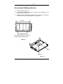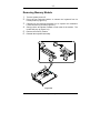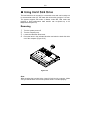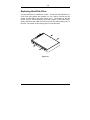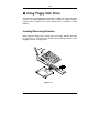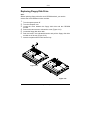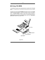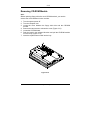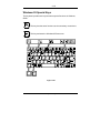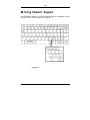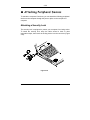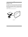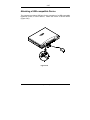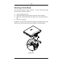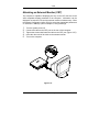
1
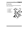
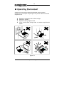
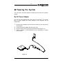
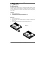
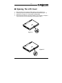
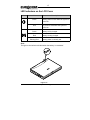
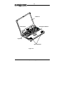
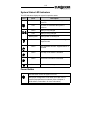
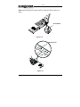
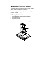
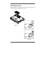
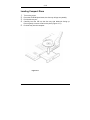
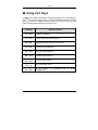
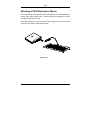
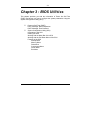
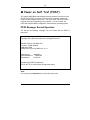
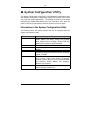
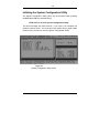
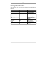
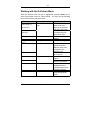
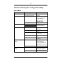
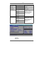
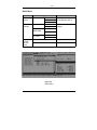
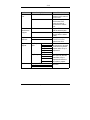
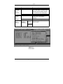
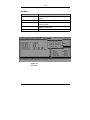
User’s Manual This manual is for the EUROCOM 5100C DeskNote ENJOY THE PURCHASE OF YOUR NEW EUROCOM 5100 DeskNote. Notice The company reserves the right to make any updates, revisions or changes to the information contained herein as and when deemed necessary. The company is under no obligation to notify any purchaser or end-user of such actions in advance or afterwards. 1999 Trademarks DeskNote is a registered trademark of Eurocom Corporation. IBM PC, OS/2, PS/2, EGA, and VGA are registered trademarks of International Business Machines Corporation. Intel, Pentium are trademarks of Intel Corporation. MS-DOS, Microsoft Windows, Windows NT and Microsoft Mouse are registered trademarks of Microsoft Corporation. Sound Blaster Pro is a trademark of Creative Labs, Inc. SystemSoft is a registered trademark of SystemSoft Corp. Other brand and product names are trademarks of their respective companies. Table of Contents Chapter 1 : Getting Started 1-1 ! Unpacking ! Operating Environment ! Powering the System By AC Power Adapter By Battery Pack ! Opening the LCD Cover LED Indicators on the LCD Cover ! Top-Front View LCD Panel Stereo Speakers Trackpad and Buttons Keyboard Microphone System Status LED Indicators Power Button ! Rear View ! Left-Side View Infrared ! Right-Side View 5.25” CD-ROM Drive Ventilation 1-2 1-3 1-4 1-4 1-5 1-6 1-7 1-8 1-8 1-8 1-8 1-8 1-8 1-10 1-10 1-12 1-14 1-15 1-16 1-16 1-16 Chapter 2 : Operation2-1 Replacing the Processor Reinstalling Heat Sink Accessing the Memory Sockets Installing Memory Module Removing Memory Module ! Using Hard Disk Drive Removing Replacing Hard Disk Drive ! Using Floppy Disk Drive Inserting/Removing Diskettes Replacing Floppy Disk Drive ! Using CD-ROM 2-2 2-3 2-5 2-6 2-7 2-8 2-8 2-9 2-10 2-10 2-11 2-12 Removing CD-ROM Module Loading Compact Discs Handling Compact Discs ! Using PC Card Sockets Inserting PC Cards Removing PC Cards ! Using Hot Keys Windows 95 Special Keys ! Using Numeric Keypad ! Using Power Management Advanced Power Management (APM 1.2) Advanced Configuration and Power Interface (ACPI) Global Standby Hard Disk Standby Suspend and Resume ! Attaching Peripheral Devices Attaching a Security Lock Attaching a Parallel Printer Attaching a TV Set Attaching a USB-compatible Device Attaching a Serial Mouse Attaching an External Monitor (CRT) Attaching a PS/2 Keyboard or Mouse Chapter 3 : BIOS Utilities 3-1 ! Power on Self Test (POST) POST Message: Normal Operation POST Message: Error Detected ! System Configuration Utility Information in the System Configuration Utility Initiating the System Configuration Utility Working with the Menu Bar Working with the Pull-down Menu Features of the System Configuration Utility Appendix A: Specifications I 2-13 2-14 2-15 2-16 2-16 2-16 2-18 2-19 2-20 2-21 2-21 2-21 2-21 2-21 2-22 2-24 2-24 2-25 2-26 2-27 2-28 2-29 2-30 3-2 3-2 3-3 3-4 3-4 3-5 3-6 3-7 3-8 1-1 Chapter 1 : Getting St arted This chapter provides you with the short instruction on your DeskNote computer system that will help you to get the basic understanding about the computer. ! ! ! ! ! ! ! ! Unpacking Operating Environment Powering the System By AC Power Adapter By Battery Pack Opening the LCD Cover Top-Front View Rear View Left-side View Right-side View Chapter 1: Getting Started 1-2 ! Unpacking Carefully unpack the DeskNote computer and the included accessories (Figure 1-1). Check the items one by one. If there is something wrong, contact your dealer immediately. " " " " " " " " DeskNote Computer. Carrying Bag. Power Adapter. Power Cord. User Manual. PS/2 Transfer Cable. Battery Pack. Drivers/Manual CD. Figure 1-1 User’s Manual 1-3 ! Operating Environment As with any other precision electronic equipment, proper care and operation of your computer will prolong the use period. Make sure that the computer is not: " " " " Exposed to excessively heat or direct sunlight. Shocked or vibrated. Exposed to strong magnetic fields. Left in a place where foreign matter or moisture may affect the system. Figure 1-2 Chapter 1: Getting Started 1-4 ! Powering the System You can use the AC power adapter or battery pack to power the computer system. By AC Power Adapter Use only the power adapter that comes with your computer. An incorrect type of power adapter will cause damage to the computer and its components. 1. Plug the power adapter cord into the AC-in socket on the rear panel of 2. 3. 4. the computer. Connect the power adapter with the power cord. Plug the power cord into a properly grounded outlet (Figure 1-3). Refer to Chapter 1, LED Indicators for more information on system power status. Figure 1-3 User’s Manual 1-5 By Battery Pack The battery pack provides power for continuous portable operation of the computer. When using the battery no external power source is required. The actual operation time is related to the application and the configuration you’re using. Inserting 1. 2. 3. Turn the computer over. Fit the battery pack firmly into the computer. The latch will click into the place when it is seated. Removing 1. 2. 3. Turn the computer over. Press the latch in the indicated direction to release the battery pack (Figure 1-4). Carefully lift the battery pack from the computer (Figure 1-5). Figure 1-4 Chapter 1: Getting Started 1-6 ! Opening the LCD Cover 1. 2. 3. 4. Move the latch to the right to release the top cover. (Figure 1-6). Lift the top cover to reveal the LCD panel and keyboard (Figure 1-7). Adjust the LCD panel to a comfortable viewing angle. Press the power button to turn the system on or off (refer to Chapter1, Top-Front View for more information on the power button). Figure 1-6 Figure 1-7 User’s Manual 1-7 LED Indicators on the LCD Cover Icon Color Description Green Battery power is used while the system is turned on. Red Green Red Blinking Red AC power is used while the system is turned on. Battery is fully charged. Battery is being charged. Battery power is critically low. Note: The light on the indicator will blink when the battery is overheated. Figure 1-8 Chapter 1: Getting Started 1-8 ! Top-Front View LCD Panel The computer provides you with a SVGA, LCD panel. Depending on the model you purchased, it can either be a 12.1” TFT, 12.1” HPA flat panel. An AGP bus video controller with 4MB-video memory drives the LCD panel. Stereo Speakers Two built-in speakers provide 3D stereo sound system. Trackpad and Buttons The pointing device features a sensitive glide pad for precise movements. It functions like a two-button mouse does. The right trackpad button is equivalent to the right mouse button; the left trackpad button is equivalent to the left mouse button. Keyboard The 84-key Windows 95 keyboard is integrated with the numeric keypad. Microphone The built-in microphone provides clear sound effect. User’s Manual 1-9 LCD Panel Microphone Trackpad and Button Keyboard Stereo Speakers Figure 1-9 Chapter 1: Getting Started 1-10 System Status LED Indicators The LED indicators display the system’s operation status. Icon Color Green Red Green Red Blinking Red Description Battery power is used while the system is turned on. AC power is used while the system is turned on. Battery is fully charged. Battery is being charged. Battery power is critically low. Green The system has entered the configured suspend mode. Green The embedded numeric keypad feature is activated Green The Caps Lock feature is activated. Green The Scroll Lock feature is activated. Green The hard disk is being accessed. Power Button Use this button to turn the system on or off. After proper configuration under SCU, this button can be used as suspend/resume hot button (refer to Chapter 3: BIOS Utilities, Power Menu for more information). User’s Manual 1-11 Note: After turning off the system, wait for a few seconds to power it on again. Power Button Figure 1-10 LED Indicators Figure 1-11 Chapter 1: Getting Started 1-12 ! Rear View AC-in Socket Plug the AC adapter into this socket for power supply. disconnect, pull the plug (not the cord) directly back. To Parallel Port This parallel port supports EPP (Enhanced Parallel Port) and ECP (Extended Capabilities Port) modes. S-Video Jack Use this jack to transmit video signal to a TV set. You may need to select the video standard (NTSC/PAL) for video display (please refer to Chapter 3, Components Menu for more information). USB Port The Universal Serial Bus (USB) port simplifies the expansion capability for peripheral devices. Serial Port The serial port features a 9-pin connector for the external addition, such as mouse or fax/modem. External Monitor (CRT) Port This port is used for transmission of the display to an external monitor. Simultaneous display in LCD screen and external CRT monitor is available. PS/2 Type Port This port is used to connect with a PS/2 type keyboard or mouse. User’s Manual 1-13 Phone Jack The phone jack is used to support the built-in modem. To use the function, attach a phone line to the jack and insert a modem card (optional) into the modem socket on the mainboard. Serial Port Parallel Port USB Port AC-in Socket CRT Port S-Video Jack PS/2 Type Port Phone Jack Figure 1-12 Chapter 1: Getting Started 1-14 ! Left-Side View PC Card Sockets There are two PC card sockets on the right side and left side. Two type II PCMCIA 3.3V/5V cards can be used to expand the system’s capability. The sockets support Zoom Video Mode and CardBus. To eject the PC card, press the appropriate eject button. 2.5” Hard Disk Drive The 2.5” hard disk drive is removable. It accepts any 2.5” hard disk drive with a height of 12.7mm or less. The system supports Master mode IDE and PIO mode 4/ATA-33 (Ultra DMA). 3.5” Floppy Disk Drive The computer provides a built-in 3.5”, 3-mode, 1.44MB floppy disk drive. To eject the disk, press the button on the top-right side. The floppy disk module can be replaced with a 12.7mm(h) LS-120 drive. (Refer to Chapter 2: Operation for more information). Headphone Jack Headphone and speakers can be attached to the system through this jack. Microphone-in Jack Use this jack to connect a microphone to the system. User’s Manual 1-15 Infrared The system adopts infrared technology as the interface for simple, fast and convenient data exchange from the computer to an infraredcompatible device. The infrared port supports IrDA (HPSIR) 1.0 mode and Amplitude Shifted Keyed IR (ASKIR) mode. For further information, please refer to the manual of the wireless device you wish to connect on how to use the point-and-shoot operation. Microphone-in Jack PC Card Socket Infrared Headphone Jack 3.5” Floppy Disk Drive 2.5” Hard Disk Drive Figure 1-13 Chapter 1: Getting Started 1-16 ! Right-Side View 5.25” CD-ROM Drive The 5.25” IDE CD-ROM module is designed to be removable. The eject button is located in the middle of the front cover of the CD-ROM drive. Pressing it will release the CD tray. Ventilation The computer vents were designed to help dissipate system’s heat produced during normal operation. Do not block or obstruct vents while DeskNote ™ is in use. PC Card Socket 5.25” CD-ROM Drive Figure 1-14 User’s Manual Ventilation 2-1 Chapter 2 : Operation The EUROCOM 5100C DeskNote has many advanced features to help you with your computer work. This chapter describes each of the computer’s hardware features and shows you how to use them. Before you begin working with the internal components of the computer, remove the battery and disconnect the AC power adapter. Make sure you wear an anti-static wrist strap to ground yourself before working with or repair the internal components. Static electricity may damage the components. ! ! ! ! ! ! ! ! ! ! ! Upgrading Processor Module Setting DIP Switch Expanding Memory Using Hard Disk Drive Using Floppy Disk Drive Using CD-ROM Using PC Card Sockets Using Hot Keys Using Numeric Keypad Using Power Management Attaching Peripheral Devices Chapter 2: Operation 2-2 ! Upgrading Processor Module The DeskNote supports Intel Celeron processor at 300MHz, 333MHz, 366MHz, 400MHz, and 433MHz Core frequencies. The Intel Celeron processor provides good performance for applications running on advanced operating systems, such as Window 95/98, Window NT, and UNIX. Replacing the Processor 1. 2. 3. 4. 5. Remove all the power sources (AC power and battery). Turn the computer over. Remove the CPU cover. Remove the screws that fasten the heat sink mounted on the processor. Carefully detach the processor from the mainboard (Figure 2-1). CPU Cover Heat Sink and Fan Processor Module Figure 2-1 User's Manual 2-3 Reinstalling Heat Sink Reinstall the CPU in the reverse order of removal. Make sure that the heat sink cable is properly installed (Figure 2-2 & 2-3). Figure 2-2 Figure 2-3 Chapter 2: Operation 2-4 ! Expanding Memory The system has two memory sockets for different RAM modules to expand the memory up to 256MB. The RAM modules should be 144-pin SODIMM (Small Outline Dual In-line Memory Module) type. The computer supports EDO, and SDRAM operation. The total memory size is automatically detected by the POST routines. To expend the memory, you have the following choice with different SDRAM combinations. Bank 0 ( 64 Bits) 8 8 16 32 16 32 64 64 32 64 128 64 128 128 128 128 128 User's Manual Bank 1 ( 64 Bits) 0 8 8 0 16 16 8 16 32 32 0 64 8 16 32 64 128 Power 3.3V Total Size 8 16 24 32 32 48 72 80 64 96 128 128 136 144 160 192 256 2-5 Accessing the Memory Sockets 1. Turn the system power off. 2. Press the two keyboard latches to elevate the keyboard from its 3. normal position (Figure 2-4). Carefully lift the keyboard assembly out to expose the mainboard. Locate the memory sockets (Figure 2-6 & Figure 2-7). 67.6mm 31.75mm Non-component area (The edges of the memory module are the non-component area.) Figure 2-6 Bank 1 Bank 0 Figure 2-7 Chapter 2: Operation 2-6 Installing Memory Module Follow the steps below to install the memory module: 1. Turn the system power off. 2. Press the two keyboard latches to elevate the keyboard from its 3. 4. 5. 6. normal position (Figure 2-4). Carefully lift the keyboard assembly out to expose the mainboard. Locate the memory sockets (Figure 2-7). Insert the memory module at a slight angle (45 ) and fit its connectors into the socket firmly (Figure 2-8). Note: Insert Bank o first, then Bank 1. Press the two edges of the memory module to make it locked into the place. Reinstall the keyboard assembly. Figure 2-8 User's Manual 2-7 Removing Memory Module 1. Turn the system power off. 2. Press the two keyboard latches to elevate the keyboard from its 3. 4. 5. 6. normal position (Figure 2-4). Carefully lift the keyboard assembly out to expose the mainboard. Locate the memory sockets (Figure 2-7). Gently pull the two latches outward on both ends of the module. The module will pop up (Figure 2-9). Remove the memory module. Reinstall the keyboard assembly. Figure 2-9 Chapter 2: Operation 2-8 ! Using Hard Disk Drive The hard disk drive is mounted in a removable case and can be taken out to accommodate other 2.5” IDE hard disk drives with a height of 12.7mm. The system supports PIO mode 4, Master mode IDE, LBA mode and provides a high performance data transfer rate at speeds up to 33 Mbytes/second (ATA-33). Removing 1. 2. 3. 4. Turn the system power off. Turn the computer over. Locate the Hard Disk Drive latch. Press the latch in the indicated direction and take the hard disk drive out of the computer (Figure 2-10). Figure 2-10 Note: When inserting the hard disk drive, insert it firmly into the computer. Make sure you feel the drive click into the position when it is seated properly. User's Manual 2-9 Replacing Hard Disk Drive The hard disk drive is contained in a case. To take the hard disk drive out of the case and replace with another one, you need to remove the two screws on each side of the case (Figure 2-11). The location of the two screws may be varied depending on different types of hard disk model. Gently disconnect the cable from the hard disk drive when taking it out of the case. Be careful not to bend any pins or crimp the cable. Figure 2-11 Chapter 2: Operation 2-10 ! Using Floppy Disk Drive The computer is equipped with a removable 1.44MB, 3.5” floppy disk drive module. It is usually designated as drive A: by default and can be used as a boot device if properly set in SCU (please refer to Chapter 3: BIOS Utilities). Inserting/Removing Diskettes When using the floppy drive, always insert your floppy diskette label-side up (Figure 2-12). To remove your diskette, press the eject button on the top-right corner of the floppy drive. Figure 2-12 User's Manual 2-11 Replacing Floppy Disk Drive Note: Before replacing floppy disk drive and CD-ROM module, you need to remove the cover between the two modules. 1. Turn the system power off. 2. Turn the computer over. 3. Locate the cover between the floppy disk drive and the CD-ROM module. 4. Remove the two screws to release the cover (Figure 2-13). 5. Locate the floppy disk drive latch. 6. Push the latch in the indicated direction and pull the floppy disk drive module out of the tray (Figure 2-14). 7. Insert the replacement module into the bay. Figure 2-13 Figure 2-14 Chapter 2: Operation 2-12 ! Using CD-ROM The DeskNote computer comes standard with a removable 5.25” CD-ROM module. It is labeled drive D: and may be used as a boot device if properly set. To insert a CD, press the Eject Button and place the CD into the Disc Tray with label-side facing up. Push the CD tray in and you are ready to start. The Busy Indicator will light up while data is being accessed or while an audio CD is playing. When the power is unexpectedly interrupted, insert an instrument such as a straightened paper clip into the Emergency Eject Hole to eject the tray (Figure 2-15). Disc Tray Emergency Eject Busy Indicator Eject Button Figure 2-15 User's Manual 2-13 Removing CD-ROM Module Note: Before replacing floppy disk drive and CD-ROM module, you need to remove the cover between the two modules. 1. Turn the system power off. 2. Turn the computer over. 3. Locate the cover between the floppy disk drive and the CD-ROM module. 4. Remove the two screws to release the cover (Figure 2-13). 5. Locate the CD-ROM latch. 6. Push the latch in the indicated direction and pull the CD-ROM module out of the tray (Figure 2-16). 7. Insert the replacement module into the bay. Figure 2-16 Chapter 2: Operation 2-14 Loading Compact Discs 1. 2. 3. 4. 5. Turn on the power. Press the CD-ROM eject button; the disc tray will pop out partially. Pull the disc tray out. Carefully load the CD into the disc tray with label-side facing up. Press it gently to ensure it fits into the place (Figure 2-17). Push the tray into the computer. Figure 2-17 User's Manual 2-15 Handling Compact Discs Proper handling of your CDs will prevent them from being damaged and ensure the accessibility of data stored in them. ❍ Hold the CD by the edges; do not touch the surface of the disc. ❍ Use clean, soft, and dry cloth to remove dust or fingerprints. ❍ Do not use pen to write on the surface. ❍ Do not attach any paper or other materials to the surface of the disk. ❍ Do not store or place the CD in the high-temperature areas. ❍ Do not use benzene, thinners, or other cleaners to clean the CD. ❍ Do not bend the compact disc. ❍ Do not drop or subject the CDs to shock. Chapter 2: Operation 2-16 ! Using PC Card Sockets The computer is equipped with two PC card sockets (previously referred to as PCMCIA). Both sockets support two 3.3V/5V type II PC cards or two 3.3V CardBus cards The PC card sockets are located on the computer’s right side and left side. The socket on left side is named socket A which supports Zoom Video Port. Inserting PC Cards 1. 2. Open the access door Align the PC card with the slot and push it in firmly until it locks into the place (Figure 2-18 & 2-19). Removing PC Cards To remove a PC card, press the appropriate eject button to eject the card from its slot. User's Manual 2-17 Figure 2-18 Eject Button Socket A Socket B Eject Button Figure 2-19 Chapter 2: Operation 2-18 ! Using Hot Keys Located on the bottom-left edge of the keyboard layout is a colored Fn key. The Fn key function allows you to change operational features instantly. When you use the following functions, press and hold the Fn key; then press the appropriate function key (Figure 2-20). Hot Keys System Features Fn + F3 Expand LCD display. Fn + F4 Control display top/center position. Fn + F6 Toggle CRT/LCD/LCD+CRT/TV/CRT+TV. Fn + F9 Decrease LCD brightness. Fn + F10 Increase LCD brightness. Fn + F11 Decrease audio volume. Fn + F12 Increase audio volume. Fn + Z Turn audio mute on/off. Fn + Esc User's Manual Put the system in a suspend state for power management. 2-19 Windows 95 Special Keys The keyboard provides two keys that have special functions in Windows 95/98: This key has the same functions as the secondary mouse does. This key activates the Windows 95 Start menu. Figure 2-20 Chapter 2: Operation 2-20 ! Using Numeric Keypad Your DeskNote features a 102-key keyboard with an integrated numeric keypad for easy numeric data input (Figure 2-21). Figure 2-21 User's Manual 2-21 ! Using Power Management The system provides you with various modes to manage its power consumption while maintaining system performance. Please refer to Chapter 3: BIOS Utilities, System Configuration Utility, Power Menu for more information. Advanced Power Management (APM 1.2) The system provides built-in Advanced Power Management (APM 1.2) support to reduce power consumption. APM function varies depending on the operation system you are using. Some operation systems do not support APM, such as Windows NT, and therefore, cannot take advantage of the system’s capabilities in this area. Advanced Configuration and Power Interface (ACPI) The ACPI interface gives the operation system (OS) direct control over the power management and Plug and Play functions of a computer. The operation system can perform the functions covered by the ACPI specification, such as system power management, device power management, and thermal management. Global Standby In Global Standby mode, the CPU clock will be stopped and most controllable peripheral devices will be power off. If the idle timer expires before any system activity is detected, the system will change from Standby mode into Suspend mode. Hard Disk Standby The system will turn off the computer’s hard disk drive motor if it has not been accessed after a specified period of time. The motor will be turned back on if the system attempts to read or write data to it. Chapter 2: Operation 2-22 Suspend and Resume When at extremely low power, you can enter suspend mode to save power. In suspend mode, all tasks are stopped and stored in memory to save power. The system features two levels of suspend mode: Powered-OnSuspend (POS) mode and Suspend-To-Disk (STD) mode. Another useful feature is resume mode. This feature allows you to turn the computer’s power off without exiting your software application. When you turn the power on again, you can resume work where you left off, because the screen display is restored as you left it. This saves time and battery power. Caution: Do not enter suspend mode when you are 1. Accessing any of the disk drives, such as HDD, FDD or CD-ROM drives. 2. Using the audio features or playing back video. 3. Playing a DOS game. Powered On Suspend (POS) Of the suspend modes, Powered-On-Suspend saves the least amount of power. However, it takes the shortest time to return to full operation. Resume from POS Mode The system can resume from Powered-On-Suspend mode by: " " " " " Alarm resume (month/day/hour/minute) Modem ring Pressing any keyboard key. Pressing the power button (if configured as Suspend/Resume function under SCU) Opening the display lid (only if the suspend mode is initiated by closing the display lid) User's Manual 2-23 Suspend To Disk (STD) Suspend to Disk is a 0-volt suspend mode for system power management. STD mode saves the maximum power but takes the longest time to return to full operation. 1. Use your operation system’s FDISK program to delete all partitions of the hard disk if any already exist on the target drive. 2. Boot the system and run the 0VMAKFIL.EXE Utility to create the Suspend to Disk partition on the hard disk. The size of Suspend to Disk partition will be the installed DRAM (n) plus 4MB integrated video RAM. :\>0VMAKFIL –Pn For example, if the system DRAM is 32MB, 0VMAKFIL will create a partition size of approximately 36MB. :\>0VMAKFIL –P32 Resume from STD Mode The system will resume from Suspend-To-Disk mode by: " " Power back on Alarm resume (month/day/hour/minute) Suspend To RAM (STR) Suspend-To-RAM management. mode is the medium level of system power Resume from STR Mode The system will resume from Suspend-To RAM mode by: " " " " Alarm resume (month/day/hour/minute) Modem ring Pressing the power button (if configured as Suspend/Resume function under SCU) Opening the display lid (only if the suspend mode is initiated by closing the display lid) Chapter 2: Operation 2-24 ! Attaching Peripheral Devices To extend the computer’s functions, you can attach the following peripheral devices to the computer through the ports or jacks on the rear panel of computer. Attaching a Security Lock The security lock is equipped to protect your computer from being stolen. To install the security lock, wrap the cable around a desk or other immovable object, then insert the locking device into the connector (Figure 2-22). Figure 2-22 User's Manual 2-25 Attaching a Parallel Printer You may connect any standard Centronics parallel printer to your computer through the parallel port. 1. Turn the system power off. 2. Connect the cable to the parallel port on the rear of the computer. 3. Tighten the screws that fasten the cable to the parallel port (Figure 223). 4. Insert the other end of the cable to the printer’s connector. Fasten the cable’s connector. 5. Turn on the printer and computer. In addition, you also need to install the manufacturer-supplied driver for the printer. Refer to the device’s user’s guide for more information. If the connected printer supports EPP (Enhanced Parallel Port) or ECP (Extended Capabilities Port) mode, please enter System Configuration Utility (SCU) to configure the required setting. Figure 2-23 Chapter 2: Operation 2-26 Attaching a TV Set The S-Video jack on the rear panel of the computer is used for transmitting video signals to a TV set. You may need to select the video standard for video display. Enter the System Configuration Utility (SCU), Components Menu to specify the appropriate TV mode. Simultaneous display on external monitor (CRT) and TV is available. You can enter the SCU to select the appropriate parameters or use the Fn + F6 keys (refer to Chapter 2, Using Hot Keys). Attach the TV set as shown below (Figure 2-24). Figure 2-24 User's Manual 2-27 Attaching a USB-compatible Device The computer provides a USB port for the connection of a USB-compatible keyboard, mouse, or other devices. Attach the device as shown below (Figure 2-25). Figure 2-25 Chapter 2: Operation 2-28 Attaching a Serial Mouse The serial port features a 9-pin connector. You can connect any serial device such as a mouse to this port. 1. Turn the system power off. 2. Connect the cable to the serial port on the rear of the computer. 3. Tighten the screws that fasten the cable to the serial port (Figure 24. 26). Turn on the computer. In addition, you may need to install the manufacturer-supplied driver for the serial mouse. Refer to the device’s user’s guide for more information. Figure 2-26 User's Manual 2-29 Attaching an External Monitor (CRT) The computer is capable of displaying not only on the LCD, but also on the XGA compatible displays attached to the computer. Information can be displayed on both the LCD and the external monitor simultaneously. Enter the System Configuration Utility (SCU) to select the appropriate parameters or use the Fn + F6 keys (refer to Chapter 2, Using Hot Keys). 1. 2. 3. 4. 5. Turn the system power off. Connect the cable to the CRT port on the rear of the computer. Tighten the screws that fasten the cable to the CRT port (Figure 2-27). Insert the other end of the cable to the external monitor. Turn on the computer. Figure 2-27 Chapter 2: Operation 2-30 Attaching a PS/2 Keyboard or Mouse The computer can be operated with a PS/2 keyboard or mouse attached by means of the PS/2 transfer cable. Attach the external keyboard or mouse as shown below (Figure 2-28). Both PS/2 type ports on the rear panel of the computer can be used for the connection of a PS/2 keyboard and mouse. Figure 2-28 User's Manual 3-1 Chapter 3 : BIOS Utili ties This chapter provides you with the information of Power On Self Test (POST) and shows you how to configure the system parameters using the System Configuration Utility (SCU). ! ! Power on Self Test (POST) POST Message: Normal Operation POST Message: Error Detected System Configuration Utility (SCU) Information in the SCU Initiating the SCU Working with the Menu Bar of the SCU Working with the Pull-Down Menu of the SCU Features of the SCU Startup Menu Memory Menu Disks Menu Components Menu Power Menu Exit Menu Chapter 3: BIOS Utilities 3-2 ! Power on Self Test (POST) The system BIOS (Basic Input/Output System) performs a series of Power On Self Test (POST) on system memory and key computer components every time the computer is turned on. If an error exists, the POST routine may halt execution (depending on the problem). If no error exists, the POST will initializes BIOS configuration, then boots the operating system. POST Message: Normal Operation You will see the following message if no error exists after the POST is performed. SystemSoft BIOS MobilePRO BIOS Version 1.01 (2482-00)-(R1.00.tr02) Copyright 1983-1996 SystemSoft Corp. All Rights Reserved 300 MHz Celeron with MMX CPU L2 Cache: 128KB Installed 4 MB Video RAM SystemSoft Plug-n-Play BIOS ver1.17.01 Base Memory 000640 Kb Extended Memory 130048 Kb Total Memory 131072 Kb Auto Detecting IDE Devices[Done] <CTRL-ALT-S> to enter System Configuration Utility Note: You may press the Spacebar key to skip the memory test. User's Manual 3-3 POST Message: Error Detected If an error is detected, you will see the following WARNING message. You may press F1 key to continue, or press the Ctrl-Alt-S keys simultaneously to enter the System Configuration Utility. SystemSoft BIOS MobilePRO BIOS Version 1.01 (2482-00)-(R1.00.tr02) Copyright 1983-1996 SystemSoft Corp. All Rights Reserved 300 MHz Celeron with MMX CPU L2 Cache: 128KB Installed 4 MB Video RAM SystemSoft Plug-n-Play BIOS ver1.17.01 Base Memory 000640 Kb Extended Memory 130048 Kb Total Memory 131072 Kb WARNING – HARD DISK CONTROLLER 1 FAILURE Auto Detecting IDE Devices[Done] <CTRL-ALT-S> to enter System Configuration Utility Press F1 to Continue Chapter 3: BIOS Utilities 3-4 ! System Configuration Utility The System Configuration Utility (SCU) is a ROM-based configuration utility that displays the system’s configuration status and provides users with a tool to set their system parameters. The settings are stored in non-volatile battery-backed CMOS RAM which saves the information even when the power is turned off, and retains it when the system is turned on again Information in the System Configuration Utility The following shows the system settings that may be changed within the System Configuration Utility. Menu Bar Items Startup Memory Disks Components Power Exit . User's Manual Pull-down Menu Items Date and Time, Fast Boot, Boot Device, Display, Enable Battery Low Beep, Enable LCD expand Mode, Enable Power On Beep, Enable PNP OS Support, Boot Password, SCU Password. Cache Systems. Enable LS120/ZIP 100 Drive, Diskette Drives, IDE Settings. COM Ports, LPT Port, PS/2 Mouse Port, Microsoft IntelliMouse Support, Keyboard Numlock, Keyboard Repeat, TV Mode Enable Power Saving, Low Power Saving, Medium Power Saving, High Power Saving, Customize, Suspend Controls, Resume Timer, Enable MODEM Ring Resume, Enable Battery Low Suspend, Advance CPU Controls. Save and Exit, Exit (No Save), Default Settings, Restore Settings, Version Info. 3-5 Initiating the System Configuration Utility The System Configuration Utility (SCU) can be accessed when pressing the Ctrl, Alt, and S keys simultaneously. <CTRL-ALT-S> to enter System Configuration Utility The above message only lasts seconds. If you miss it, the computer will initiate the boot process. You must reboot the system and try again within the time limit if you want to enter the System Configuration Utility. Figure 3-1 System Configuration Utility (SCU) Chapter 3: BIOS Utilities 3-6 Working with the Menu Bar After entering the SCU, you may use the following keys to work with the menu bar. Keys Alt Left arrow (←) Action Activate menus Select menu bar item. Right arrow (→) The highlighted letter key Mouse left button Spacebar Enter Mouse right button Esc User's Manual Accept menu bar item Cancel current action Description Activate the System Configuration Utility. Move to a menu bar item on the left. Move to a menu bar item on the right. Move to the corresponding menu bar item. Enter the selected menu bar item to configure settings. Undo the current command. 3-7 Working with the Pull-down Menu When the desired menu bar item is highlighted, press the Enter key to enter the pull-down menu for values setting. You may use the following keys to work with the pull-down menu. Keys Down arrow (↓) Action Select pull-down menu item. Up arrow (↑) The highlighted letter key Tab Select a control Down/Up arrows (↓)(↑) Spacebar Change values Accept entries Enter Esc Reject entries Enter Alt Activate accelerators Esc Quit Chapter 3: BIOS Utilities Description Move to the next pulldown menu item. Move to the previous pull-down menu item. Move to the corresponding pulldown menu item. Move between the options. Modify the settings. Enable/disable the specified function. When a check mark (√) appears, the function is on. Choose <OK> from a list of options. Undo the current setting. Choose <Cancel> from a list of options. Initiate all the highlighted letters corresponding to their respective options. Press the Esc key to close the pull-down menu. 3-8 Features of the System Configuration Utility Startup Menu Item Date and Time Fast Boot Boot Device Display Setting/Option Day/Month/Year Hour/Minute/Second Enable Disable Diskette A Hard Disk C CD-ROM Drive LCD CRT LCD + CRT TV CRT + TV Enable Battery Low Beep Enable LCD Expand Mode Enable Disable Enable Disable User's Manual Function Set the current date and time. Initialize and quickly boot the system in a few seconds by skipping certain diagnostic tests. Disable the above. Specify where the system boots from. Activate the system’s LCD panel. Activate an external monitor. Activate both the LCD and the CRT. Activate an external TV. Activate both the CRT and the TV. The system emits a series of warning beeps sound when the battery power becomes low. Disable the above. Stretch the display to fill the entire viewing area of the LCD panel. Disable the above. 3-9 Item Enable Power on Beep Enable PNP OS Support Boot Password SCU Password Setting/Option Enable Disable Enable Disable Enter old Power-On Password Enter new Power-On Password Verify new Power-On Password Enable Password to Power-On Enter old Setup Password Enter new Setup Password Verify new Setup Password Enable Setup Password Function Enable or disable Power on Beep. Enable or disable PNP OS Support. Set password for booting computer. Users are authorized to start the system after entering correct password. Set password for modifying SCU. Users are authorized to change the SCU setting after entering correct password. Figure 3-2 Startup Menu Chapter 3: BIOS Utilities 3-10 Memory Menu Item Cache Systems Setting/Option L1 Disabled Cache Write Back L2 Cache BIOS Shadow Video Shadow Disabled Write Back Cached Not Cached Cached Not Cached Function Disable the processor’s internal cache. Enable the Processor’s internal write-back cache. Disable the L2 cache controller. Enable the LS write-back cache. The process of shadowing copies instructions from system BIOS into RAM to improve system performance. Disable the above. The process of shadowing copies instructions from video BIOS into RAM to improve system performance. Disable the above. Figure 3-3 Memory Menu User's Manual 3-11 Disks Menu Item Diskette Drives IDE Settings Setting/Option Drive A None 1.44 Mb 2.88 Mb Primary HDD Drive Enabled PIO Mode CD-ROM / Drive Enabled DVD-ROM PIO Mode LS120 /ZIP/ nd 2 HDD Enable LS120/ ZIP100 Drive Function Specify the drive types for the diskette drive A. Enable enhanced IDE settings. Drive Enabled PIO Mode Enable Enable the LS120 drive. Disable Disable the LS 120 drive. Figure 3-4 Disks Menu Chapter 3: BIOS Utilities 3-12 Components Menu Item COM Ports LPT Port Setting/Option COM A I/O None Settings COM1, 3F8, IRQ4 COM2, 2F8, IRQ3 COM3, 3E8, IRQ10 COM4, 2E8, IRQ11 COM B I/O None Settings COM1, 3F8, IRQ4 COM2, 2F8, IRQ3 COM3, 3E8, IRQ10 COM4, 2E8, IRQ11 Mode Normal (16550) Setting for IrDA (HPSIR) COM B ASK IR FAST IR DMA DMA 0 Setting for DMA 1 Fast IR DMA 3 Port Address Port Definition DMA Setting For ECP Mode EPP Type User's Manual Function Specify the COM A configuration. (COM3 & COM4 Only for DOS mode and Non-PnP OS.) Specify the COM B configuration. (COM3 & COM4 Only for DOS mode and Non-PnP OS.) Define the COM B hardware. Specify the Fast IR DMA configuration. Specify the LPT port None and IRQ configuration. LPT1, Addr 378, IRQ7 LPT2, Addr 278, IRQ5 LPT3, Addr 3BC, IRQ7 Standard AT (Centronics) Bi-directional (PS-2) Enhanced Parallel (EPP) Extended Capabilities (ECP) DMA 1 Specify the ECP DMA DMA 3 configuration. EPP 1.9 Specify the EPP type. 3-13 Item PS/2 Mouse Port Setting/Option Enable Disable Microsoft Intellimouse Support Enable Disable Keyboard Numlock Enable Disable Keyboard Repeat Key Repeat Rate Key Delay TV Mode 2 cps 6 cps 10 cps 15 cps 20 cps 30 cps 1/4 sec 1/2 sec 3/4 sec 1 sec Japanese NTSC US NTSC PAL Function Enable the system’s trackpad or an external PS/2 mouse. Disable the trackpad or PS/2 mouse if an external mouse is connected to COM A port. Support PS/2 mouse with the wheel button. Do not support PS/2 mouse with the wheel button. Specify whether Num Lock is on or off at system boot time. Define the rate (characters per second) at which the keyboard repeats while a key is depressed. Specify the amount of time (second) that will pass after a key is depressed before the key starts to repeat. Specify the TV mode selection Chapter 3: BIOS Utilities 3-14 Figure 3-5 Components Menu User's Manual 3-15 Power Menu Item Enable Power Saving Low Power Saving Setting/Option Enable Disable Enable Disable Medium Power Saving Enable Disable High Power Saving Enable Disable Customize Disk Standby 5 sec 10 sec 15 sec 20 sec 30 sec Always on Global Timeout 1 min 2 min 4 min 6 min 8 min 12 min 16 min Always on Chapter 3: BIOS Utilities Function Enable/Disable all power saving features. Enable/Disable the power saving to its lowest which results in max. performance but shortest battery life. Enable/Disable the power saving to its medium which results in both moderate performance and battery life. Enable/Disable the power saving to its highest which results in min. performance but longest battery life. The hard disk will be put on standby if it is not accessed within the specified period. Hard disk power will be restored when the disk drive is accessed again. The system power will be reduced if the system has been idle over the specified period. System power will be restored when any system activity is detected. 3-16 Item Suspend Controls Setting/Option Power Power Button On/Off Function Suspend/ Resume Suspend Type Suspend Timeout Resume Timer Alarm Resume Suspend to Disk Suspend to RAM Powered on Suspend 1 min 5 min 10 min 20 min 30 min Never Enable Function The power button is switched to turn the system on or off. The power button acts as a suspend/resume button for switching the system between a working state and the suspend mode. Pressing the power button for more than four seconds will generate a power button over-ride event to switch the system from a working state to the Soft-Off state. Specify the suspend mode for power management. If the system has been idle for the specified period, the system will enter user-defined suspend. Resume the system from the configured suspend mode when resume alarm timer expires. Disable Resume Month/Day/Hour/ Minute User's Manual The system will resume at the specified time (month, day, hour and minute). 3-17 Item Enable MODEM Ring Resume Enable Battery Low Suspend Advance CPU Controls Setting/Option Enable Disable Enable Disable Clock Control Mechanism Full Mode Function Resume the system from STR or POS mode when a modem ring is detected (which modem should be connected to the serial port). Disable the above. Automatically suspend the system to disk upon a low battery condition. Disable the above. Specify the type of Processor Clock Control. Doze Mode Figure 3-6 Power Menu Chapter 3: BIOS Utilities 3-18 Exit Menu Item Save and Exit Exit (No Save) Default Settings Restore Settings Version Info Figure 3-7 Exit Menu User's Manual Function Save the current settings and reboot the system. Exit without saving any current changes. Restore the default settings (the original ones found in ROM). Restore the current setup settings to the original custom ones. Show current BIOS version information. I Appendix A: Specifications This following are the features and specifications of the DeskNote computer. ! Processor − − Intel® Celeron™ processors 300A/333/366/400/433 MHz Intel® Mobile Pentium® II / Celeron™ processors /333/366/400/433 MHz ! Memory − − − − Two 144pins SODIMM sockets Supports EDO/Sync DRAM SODIMM (3.3V) 8/16/32/64/128 MB module (optional) Expendable memory up to 256MB. ! System BIOS − − 256KB Flash ROM SystemSoft, Plug and Play 1.0a, ACPI (1.0) ! Display − − − − − − − − − SVGA flat panel 12.1” TFT S3 ViRGE MX+ AGP 1X 64-bit hardware 2D/3D Accelerator Graphics Engine TV-out with Marco Vision® V7.1 anti-copy technology 4MB display memory SGRAM type CRT resolution up to 1280x1024x16M DuoView™ display capability under Windows 98 Support Zoomed Video Port Support Software MPEG II playback (option). ! Storage − − − − 3.5” 3-mode FDD/12.7mm(h) LS-120 DVD-ROM (12.7mm)/CD-ROM (24X speed, 12.7mmH 9.5mmH)/CD-RW (12.7mm) 2.5” 12.7mm(h) HDD, support LBA mode Support Master mode IDE, PIO mode 4/ATA-33 (Ultra DMA) or II ! Audio − − − − − − − 3D stereo sound system Compatible Sound-Blaster PRO™ version 3.01 IIS interface for external ZV port or MPEG audio Built-in microphone Built-in 2 speakers Software Wavetable FM music synthesizer 16 bits stereo sound system ! PC Card Sockets − − Two type II (PCI) PCMCIA 3.3V/5V sockets Support Zoom Video Port (Socket A)/CardBus (PC Card95) ! Interface − − − − − − − − − − − − Built-in trackpad (PS/2) One USB port One serial port One parallel port (LPT1), support ECP/EPP 1.7a and 1.9 Infrared file transfer, IrDA 1.0/ASKIR External CRT monitor One S-Video jack for TV output One External keyboard/mouse (PS/2 type) port One headphone jack One microphone jack One RJ-11 jack for Plug & Play Modem Accessory (option) DC-in jack ! Communication − − Wireless Infrared transfer, IrDA 1.0 compliant 56K Plug & Play Modem v.90 compliant (option) ! Power Management − − − − − − − Support APM v1.2 Support ACPI v1.0 Soft Off by system Power button Support suspend to disk Battery low suspend Resume from alarm time Resume from modem ring (COM port only) User’s Manual III ! Power − − Full range AC adapter – AC in 100-240V, 47-63Hz Support one removable Ni-MH/Li-Ion Battery ! Size & Weight − − 280mm(w)x240mm(d)x39.5mm(h) 2.8kg (with Lithium-Ion battery) ! Keyboard − 84 keys Win95 keyboard include numeric keypad. ! Environment − − Temperature: Operating: 5°C~35°C, Non-Operating: 20°C~60°C Humidity Operating: 20%~80%, Non-Operating: 10%~90% ! Optional − − − − − − Ni-MH Battery Smart Li-Ion Battery DVD-ROM Drive Kit MPEG playback cable Car Adapter Internal 56K v.90 Win-Modem