1
SiBE341001
DRAFT
-Q
RQYQ140 · 180PY1, RQCYQ280~540PY1
R-410A Heat Pump 50Hz
RQCEQ280~848PY1
R-410A Heat Recovery 50Hz
SiBE341001
-Q R-410A
Heat Pump /
Heat Recovery 50Hz
1. Introduction ............................................................................................ iv
1.1 Safety Cautions ....................................................................................... iv
1.2 PREFACE ............................................................................................. viii
Part 1 General Information ........................................................... 1
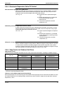
1. Model Names of Indoor / Outdoor Units..................................................2
2. External Appearance...............................................................................3
2.1 Outdoor Units ...........................................................................................3
3. Combination of Outdoor Units.................................................................4
4. Model Selection.......................................................................................5
Part 2 Specifications .................................................................... 6
1. Specifications ..........................................................................................7
1.1 Outdoor Units ...........................................................................................7
1.2 BS Units .................................................................................................16
Part 3 Refrigerant Circuit ........................................................... 18
1. Refrigerant Circuit .................................................................................19
1.1 RQYQ140 · 180PY1, RQEQ140 ~ 212PY1 ...........................................19
1.2 BS Unit ...................................................................................................21
2. Functional Parts Layout ........................................................................23
2.1 RQYQ140 · 180PY1, RQEQ140 ~ 212PY1............................................23
3. Refrigerant Flow for Each Operation Mode...........................................24
3.1 RQYQ140 · 180PY1 ...............................................................................24
3.2 RQCEQ280 ~ 848PY1 ...........................................................................27
Part 4 Function............................................................................ 34
1. Function General...................................................................................35
1.1 Operation Mode......................................................................................35
1.2 Symbol ...................................................................................................36
2. Detailed Control Functions....................................................................37
2.1
2.2
2.3
2.4
2.5
2.6
2.7
Stop Operation .......................................................................................37
Standby ..................................................................................................37
Rotation Control .....................................................................................37
Startup Control .......................................................................................38
Normal Operation ...................................................................................39
Protection Control...................................................................................47
Special Control .......................................................................................52
Part 5 Test Operation ................................................................. 61
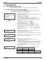
1. Test Operation ......................................................................................62
1.1 Procedure and Outline ...........................................................................62
i
Table of Contents
SiBE341001
1.2 Check Operation ....................................................................................65
1.3 Checking in Normal Operation ...............................................................68
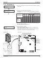
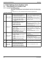
2. Field Setting from Outdoor Unit.............................................................69
2.1 Field Setting from Outdoor Unit..............................................................69
Part 6 Troubleshooting ............................................................... 92
1. Symptom-based Troubleshooting .........................................................94
2. Troubleshooting by Remote Controller .................................................97
2.1
2.2
2.3
2.4
2.5
2.6
2.7
2.8
2.9
2.10
2.11
2.12
2.13
2.14
2.15
2.16
2.17
2.18
2.19
2.20
2.21
2.22
2.23
2.24
2.25
2.26
2.27
2.28
2.29
2.30
2.31
2.32
2.33
2.34
Table of Contents
The INSPECTION / TEST Button...........................................................97
Self-diagnosis by Wired Remote Controller ...........................................98
Remote Controller Service Mode ...........................................................99
Test Run Mode.....................................................................................102
Remote Controller Self-Diagnosis Function .........................................102
“E1” Outdoor Unit: PCB Defect .............................................................110
“E2” Outdoor Unit: Actuation of High Pressure Switch..........................111
“E3” Outdoor Unit: Actuation of High Pressure Switch..........................112
“E4” Outdoor Unit: Actuation of Low Pressure Sensor..........................114
“E5” Outdoor Unit: Inverter Compressor Motor Lock.............................116
“E7” Outdoor Unit: Malfunction of Outdoor Unit Fan Motor ...................118
“E9” Outdoor Unit: Malfunction of Electronic
Expansion Valve Coil (Y1E~Y3E) ........................................................121
“F3” Outdoor Unit: Abnormal Discharge Pipe Temperature..................123
“F4” Outdoor Unit: Humidity alarm ........................................................125
“F9” Outdoor Unit : Malfunction of BS Unit Electronic
Expansion Valve...................................................................................127
“H7” Outdoor Unit: Abnormal Outdoor Fan Motor Signal ......................129
“H9” Outdoor Unit: Malfunction of Thermistor (R1T) for Outdoor Air.....131
“J3, J4, J5, J6, J7, J8, J9” Outdoor Unit: Malfunction
of Outdoor unit Thermistor ...................................................................132
“JA” Outdoor Unit: Malfunction of High Pressure Sensor......................134
“JC” Outdoor Unit: Malfunction of Low Pressure Sensor ......................136
“L1” Outdoor Unit: Malfunction of Inverter PCB ....................................138
“L4” Outdoor Unit: Malfunction of Inverter Radiating Fin
Temperature Rise.................................................................................140
“L5” Outdoor Unit: Momentary Overcurrent of Inverter Compressor ....142
“L8” Outdoor Unit: Momentary Overcurrent of Inverter Compressor ....144
“L9” Outdoor Unit: Inverter Compressor Starting Failure ......................146
“LC” Outdoor Unit: Malfunction of Transmission between Inverter
and Main PCB ......................................................................................149
“P1” Outdoor Unit: Inverter Over-Ripple Protection...............................151
“P4” Outdoor Unit: Malfunction of Inverter Radiating Fin
Temperature Rise Sensor ....................................................................153
“PJ” Outdoor Unit: Faulty Field Setting after Replacing Main PCB or
Faulty Combination of PCB ..................................................................154
“U1” Reverse Phase, Open Phase ........................................................156
“U2” Outdoor Unit: Power Supply Insufficient
or Instantaneous Failure.......................................................................157
“U3” Outdoor Unit: Check Operation is not Executed............................160
“U4” Malfunction of Transmission between Indoor Units
and Outdoor Units ................................................................................162
“U7” Outdoor Unit: Transmission Failure (Across Outdoor Units) .........165
ii
SiBE341001
2.35 “U8” Indoor Unit: Malfunction of Transmission between Main
and Sub Remote Controllers ................................................................172
2.36 “U9” Indoor Unit: Malfunction of Transmission between Indoor
and Outdoor Units in the Same System ...............................................173
2.37 “UA” Improper Combination of Indoor, BS and Outdoor Units,
Indoor Units and Remote Controller.....................................................174
2.38 “UC” Address Duplication of Centralized Controller...............................182
2.39 “UE” Malfunction of Transmission between Centralized Controller
and Indoor Unit.....................................................................................183
2.40 “UF” System is not Set yet.....................................................................186
2.41 “UH” Malfunction of System, Refrigerant System Address Undefined...187
Part 7 Appendix......................................................................... 205
1. Piping Diagrams..................................................................................206
1.1 Outdoor Unit .........................................................................................206
1.2 BS Unit .................................................................................................207
2. Wiring Diagrams for Reference...........................................................210
2.1 Outdoor Unit .........................................................................................210
2.2 BS Unit .................................................................................................211
3. Option List ...........................................................................................214
3.1 Option Lists (Outdoor Unit)...................................................................214
4. Example of connection (R-410A Type) ...............................................216
iii
Table of Contents
SiBE341001
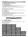
Introduction
1. Introduction
1.1
Safety Cautions
Cautions and
Warnings
Be sure to read the following safety cautions before conducting repair work.
Warning” and “
Caution”. The “
The caution items are classified into “
Warning”
items are especially important since they can lead to death or serious injury if they are not
followed closely. The “
Caution” items can also lead to serious accidents under some
conditions if they are not followed. Therefore, be sure to observe all the safety caution items
described below.
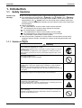
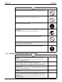
About the pictograms
This symbol indicates an item for which caution must be exercised.
The pictogram shows the item to which attention must be paid.
This symbol indicates a prohibited action.
The prohibited item or action is shown inside or near the symbol.
This symbol indicates an action that must be taken, or an instruction.
The instruction is shown inside or near the symbol.
After the repair work is complete, be sure to conduct a test operation to ensure that the
equipment operates normally, and explain the cautions for operating the product to the
customer
1.1.1 Caution in Repair
Warning
Be sure to disconnect the power cable plug from the plug socket before
disassembling the equipment for a repair.
Working on the equipment that is connected to a power supply can cause an
electrical shook.
If it is necessary to supply power to the equipment to conduct the repair or
inspecting the circuits, do not touch any electrically charged sections of the
equipment.
If the refrigerant gas discharges during the repair work, do not touch the
discharging refrigerant gas.
The refrigerant gas can cause frostbite.
When disconnecting the suction or discharge pipe of the compressor at the
welded section, release the refrigerant gas completely at a well-ventilated
place first.
If there is a gas remaining inside the compressor, the refrigerant gas or
refrigerating machine oil discharges when the pipe is disconnected, and it can
cause injury.
If the refrigerant gas leaks during the repair work, ventilate the area. The
refrigerant gas can generate toxic gases when it contacts flames.
The step-up capacitor supplies high-voltage electricity to the electrical
components of the outdoor unit.
Be sure to discharge the capacitor completely before conducting repair work.
A charged capacitor can cause an electrical shock.
Do not start or stop the air conditioner operation by plugging or unplugging the
power cable plug.
Plugging or unplugging the power cable plug to operate the equipment can
cause an electrical shock or fire.
iv
Introduction
SiBE341001
Caution
Do not repair the electrical components with wet hands.
Working on the equipment with wet hands can cause an electrical shock.
Do not clean the air conditioner by splashing water.
Washing the unit with water can cause an electrical shock.
Be sure to provide the grounding when repairing the equipment in a humid or
wet place, to avoid electrical shocks.
Be sure to turn off the power switch and unplug the power cable when cleaning
the equipment.
The internal fan rotates at a high speed, and cause injury.
Do not tilt the unit when removing it.
The water inside the unit can spill and wet the furniture and floor.
Be sure to check that the refrigerating cycle section has cooled down
sufficiently before conducting repair work.
Working on the unit when the refrigerating cycle section is hot can cause burns.
Use the welder in a well-ventilated place.
Using the welder in an enclosed room can cause oxygen deficiency.
1.1.2 Cautions Regarding Products after Repair
Warning
Be sure to use parts listed in the service parts list of the applicable model and
appropriate tools to conduct repair work. Never attempt to modify the
equipment.
The use of inappropriate parts or tools can cause an electrical shock,
excessive heat generation or fire.
When relocating the equipment, make sure that the new installation site has
sufficient strength to withstand the weight of the equipment.
If the installation site does not have sufficient strength and if the installation
work is not conducted securely, the equipment can fall and cause injury.
Be sure to install the product correctly by using the provided standard
installation frame.
Incorrect use of the installation frame and improper installation can cause the
equipment to fall, resulting in injury.
Be sure to install the product securely in the installation frame mounted on a
window frame.
If the unit is not securely mounted, it can fall and cause injury.
Be sure to use an exclusive power circuit for the equipment, and follow the
technical standards related to the electrical equipment, the internal wiring
regulations and the instruction manual for installation when conducting
electrical work.
Insufficient power circuit capacity and improper electrical work can cause an
electrical shock or fire.
v
For integral units
only
For integral units
only
SiBE341001
Introduction
Warning
Be sure to use the specified cable to connect between the indoor and outdoor
units. Make the connections securely and route the cable properly so that there
is no force pulling the cable at the connection terminals.
Improper connections can cause excessive heat generation or fire.
When connecting the cable between the indoor and outdoor units, make sure
that the terminal cover does not lift off or dismount because of the cable.
If the cover is not mounted properly, the terminal connection section can cause
an electrical shock, excessive heat generation or fire.
Do not damage or modify the power cable.
Damaged or modified power cable can cause an electrical shock or fire.
Placing heavy items on the power cable, and heating or pulling the power cable
can damage the cable.
Do not mix air or gas other than the specified refrigerant (R-410A) in the
refrigerant system.
If air enters the refrigerating system, an excessively high pressure results,
causing equipment damage and injury.
If the refrigerant gas leaks, be sure to locate the leak and repair it before
charging the refrigerant. After charging refrigerant, make sure that there is no
refrigerant leak.
If the leak cannot be located and the repair work must be stopped, be sure to
perform pump down and close the service valve, to prevent the refrigerant gas
from leaking into the room. The refrigerant gas itself is harmless, but it can
generate toxic gases when it contacts flames, such as fan and other heaters,
stoves and ranges.
When replacing the coin battery in the remote controller, be sure to disposed
of the old battery to prevent children from swallowing it.
If a child swallows the coin battery, see a doctor immediately.
Caution
Installation of a leakage breaker is necessary in some cases depending on the
conditions of the installation site, to prevent electrical shocks.
Do not install the equipment in a place where there is a possibility of
combustible gas leaks.
If a combustible gas leaks and remains around the unit, it can cause a fire.
Be sure to install the packing and seal on the installation frame properly.
For integral units
If the packing and seal are not installed properly, water can enter the room and only
wet the furniture and floor.
1.1.3 Inspection after Repair
Warning
Check to make sure that the power cable plug is not dirty or loose, then insert
the plug into a power outlet all the way.
If the plug has dust or loose connection, it can cause an electrical shock or fire.
If the power cable and lead wires have scratches or deteriorated, be sure to
replace them.
Damaged cable and wires can cause an electrical shock, excessive heat
generation or fire.
Do not use a joined power cable or extension cable, or share the same power
outlet with other electrical appliances, since it can cause an electrical shock,
excessive heat generation or fire.
vi
Introduction
SiBE341001
Caution
Check to see if the parts and wires are mounted and connected properly, and
if the connections at the soldered or crimped terminals are secure.
Improper installation and connections can cause excessive heat generation,
fire or an electrical shock.
If the installation platform or frame has corroded, replace it.
Corroded installation platform or frame can cause the unit to fall, resulting in
injury.
Check the grounding, and repair it if the equipment is not properly grounded.
Improper grounding can cause an electrical shock.
Be sure to measure the insulation resistance after the repair, and make sure
that the resistance is 1 Mohm or higher.
Faulty insulation can cause an electrical shock.
Be sure to check the drainage of the indoor unit after the repair.
Faulty drainage can cause the water to enter the room and wet the furniture
and floor.
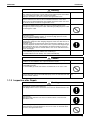
1.1.4 Using Icons
Icons are used to attract the attention of the reader to specific information. The meaning of each
icon is described in the table below:
1.1.5 Using Icons List
Icon
Type of
Information
Description
Note
A “note” provides information that is not indispensable, but may
nevertheless be valuable to the reader, such as tips and tricks.
Caution
A “caution” is used when there is danger that the reader, through
incorrect manipulation, may damage equipment, loose data, get
an unexpected result or has to restart (part of) a procedure.
Warning
A “warning” is used when there is danger of personal injury.
Reference
A “reference” guides the reader to other places in this binder or
in this manual, where he/she will find additional information on a
specific topic.
Note:
Caution
Warning
vii
SiBE341001
1.2
Introduction
PREFACE
Thank you for your continued patronage of Daikin products.
This is the new service manual for Daikin's Year 2010 VRVIII-Q series Heat Pump System.
Daikin offers a wide range of models to respond to building and office air conditioning needs.
We are confident that customers will be able to find the models that best suit their needs.
This service manual contains information regarding the servicing of VRVIII-Q series R-410A
Heat Pump, Heat Recovery System.
March, 2010
After Sales Service Division
viii
SiBE341001
Part 1
General Information
1. Model Names of Indoor / Outdoor Units..................................................2
2. External Appearance...............................................................................3
2.1 Outdoor Units ...........................................................................................3
3. Combination of Outdoor Units.................................................................4
4. Model Selection.......................................................................................5
1
General Information
SiBE341001
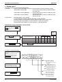
Model Names of Indoor / Outdoor Units
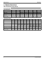
1. Model Names of Indoor / Outdoor Units
Outdoor Unit
Series
Heat Pump
Heat Recovery
Model Name
RQYQ
RQEQ
140P
140P
180P
180P
100P
Model Name
160P
Power Supply
212P
Y1
BS Unit
Type
Heat Recovery Series
BSVQ
BSV
4Q100P
6Q100P
250P
Power Supply
V18
V1
Power Supply: Y1 : 3φ, 380~415V, 50Hz
V1 : 1φ, 220~240V, 50Hz
General Information
2
External Appearance
SiBE341001
2. External Appearance
2.1
3
Outdoor Units
RQYQ140, 180PY1
RQEQ140, 180, 212PY1
RQCYQ280, 360PY1
RQCEQ280, 360PY1
5, 6.5, 7.5 HP
10, 13 HP
RQCYQ460, 500, 540PY1
RQCEQ460, 500, 540, 636PY1
RQCEQ712, 744, 816, 848PY1
16, 18, 20, 22 HP
24, 26, 28, 30 HP
General Information
SiBE341001
Combination of Outdoor Units
3. Combination of Outdoor Units
Heat Pump Series
System
Capacity
5HP
6.5HP
10HP
13HP
16HP
18HP
20HP
Number of
Units
1
1
2
2
3
3
3
RQYQ140PY1
RQYQ180PY1
●
●
●●
●●
●
●●
●
●●
●●●
Outdoor Unit Multi
Connection Piping Kit (Option)
—
BHFP22P36C
BHFP22P54C
Heat Recovery Series
System
Capacity
10HP
13HP
16HP
18HP
20HP
22HP
24HP
26HP
28HP
30HP
Number of
RQEQ140PY1 RQEQ180PY1 RQEQ212PY1
Units
2
●●
●●
2
3
●●
●
3
●
●●
3
●●●
3
●●●
4
●
●●
●
4
●
●
●●
4
●
●●●
4
●●●●
General Information
Outdoor Unit Multi
Connection Piping Kit (Option)
BHFP26P36C
BHFP26P63C
BHFP26P84C
4
Model Selection
SiBE341001
4. Model Selection
VRV III Heat Recovery Series
Connectable indoor units number and capacity
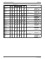
Heat Pump Series
HP
5HP
6.5HP
10HP
13HP
16HP
18HP
20HP
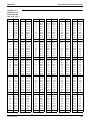
System name
RQYQ140PY1 RQYQ180PY1 RQCYQ280PY1 RQCYQ360PY1 RQCYQ460PY1 RQCYQ500PY1 RQCYQ540PY1
Outdoor unit 1
RQYQ140PY1 RQYQ180PY1 RQYQ140PY1 RQYQ180PY1 RQYQ140PY1 RQYQ140PY1 RQYQ180PY1
Outdoor unit 2
–
–
Outdoor unit 3
–
–
RQYQ140PY1 RQYQ180PY1 RQYQ140PY1 RQYQ180PY1 RQYQ180PY1
–
–
Total number of connectable
indoor units
8
10
16
20
26
29
33
Total capacity of connectable
indoor units (kW)
7.0 ~ 18.2
9.0 ~ 23.4
14.0 ~ 36.4
17.8 ~ 46.2
22.5 ~ 58.5
25.0 ~ 65.0
28.0 ~ 72.8
RQYQ180PY1 RQYQ180PY1 RQYQ180PY1
Heat Recovery Series
HP
10HP
13HP
16HP
18HP
20HP
22HP
24HP
26HP
28HP
30HP
System name
RQCEQ
280PY1
RQCEQ
360PY1
RQCEQ
460PY1
RQCEQ
500PY1
RQCEQ
540PY1
RQCEQ
636PY1
RQCEQ
712PY1
RQCEQ
744PY1
RQCEQ
816PY1
RQCEQ
848PY1
Outdoor unit 1
RQEQ
140PY1
RQEQ
180PY1
RQEQ
180PY1
RQEQ
180PY1
RQEQ
180PY1
RQEQ
212PY1
RQEQ
212PY1
RQEQ
212PY1
RQEQ
212PY1
RQEQ
212PY1
Outdoor unit 2
RQEQ
140PY1
RQEQ
180PY1
RQEQ
140PY1
RQEQ
180PY1
RQEQ
180PY1
RQEQ
212PY1
RQEQ
180PY1
RQEQ
212PY1
RQEQ
212PY1
RQEQ
212PY1
Outdoor unit 3
–
–
RQEQ
140PY1
RQEQ
140PY1
RQEQ
180PY1
RQEQ
212PY1
RQEQ
180PY1
RQEQ
180PY1
RQEQ
212PY1
RQEQ
212PY1
Outdoor unit 4
–
–
–
–
–
–
RQEQ
140PY1
RQEQ
140PY1
RQEQ
180PY1
RQEQ
212PY1
Total number of connectable
indoor units
16
20
26
29
33
36
40
43
47
50
Total capacity of connectable
indoor units (kW)
14.0 ~
36.4
18.0 ~
46.2
23.0 ~
59.8
25.0 ~
65.0
27.0 ~
70.2
31.8 ~
82.7
35.6 ~
92.6
37.2 ~
96.7
40.8 ~
106
42.4 ~
110
5
General Information
SiBE341001
Part 2
Specifications
1. Specifications ..........................................................................................7
1.1 Outdoor Units ...........................................................................................7
1.2 BS Units .................................................................................................16
Specifications
6
Specifications
SiBE341001
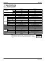
1. Specifications
1.1
Outdoor Units
Heat Pump Series <RQ(C)YQ-P>
Model Name
★1 Cooling Capacity
★2 Heating Capacity
kcal / h
RQYQ140PY1
12,000
RQYQ180PY1
15,500
Btu / h
47,800
61,400
kW
14.0
18.0
kcal / h
13,800
17,200
Btu / h
54,600
68,200
kW
16.0
20.0
Ivory White 5Y7.5/1
Ivory White 5Y7.5/1
1680×635×765
Cross Fin Coil
1680×635×765
Cross Fin Coil
Casing Color
Dimensions: (H×W×D)
Heat Exchanger
mm
Type
Comp.
Hermetically Sealed Scroll Type
Hermetically Sealed Scroll Type
Piston Displacement
m³/h
13.34
15.75
Number of Revolutions
Motor Output×Number
of Units
r.p.m
6,300
7,440
kW
Starting Method
Type
Fan
Motor Output
Airflow Rate
kW
m³/min
Drive
Connecting
Pipes
Liquid Pipe
Gas Pipe
Mass (Weight)
kg
3.3×1
Soft Start
Propellor Fan
Propellor Fan
0.35×1
95
0.35×1
110
Direct Drive
Direct Drive
φ9.5 C1220T (Brazing Connection)
φ9.5 C1220T (Brazing Connection)
φ15.9 C1220T (Brazing Connection)
φ19.1 C1220T (Brazing Connection)
175
High Pressure Switch, Fan Driver Overload Protector,
Overcurrent Relay, Inverter Overload Protector
Safety Devices
Defrost Method
Capacity Control
Refrigerant
2.8×1
Soft Start
Refrigerant Name
Charge
Control
Refrigerator Oil
%
Deicer
25~100
Deicer
21~100
kg
R-410A
11.1
R-410A
11.1
Electronic Expansion Valve
Refer to the nameplate of compressor
Electronic Expansion Valve
Refer to the nameplate of compressor
Installation Manual, Operation Manual, Clamps
Standard Accessories
Drawing No.
175
High Pressure Switch, Fan Driver Overload Protector,
Overcurrent Relay, Inverter Overload Protector
4D066320A
Installation Manual, Operation Manual, Connection Pipes,
Clamps
4D066321A
Notes:
★1 Indoor temp. : 27°CDB, 19.0°CWB / outdoor temp. : 35°CDB / Equivalent piping length : 7.5m, level
difference : 0m.
★2 Indoor temp. : 20°CDB / outdoor temp. : 7°CDB, 6°CWB / Equivalent piping length : 7.5m, level difference
: 0m.
7
Conversion Formulae
kcal/h=kW×860
Btu/h=kW×3412
cfm=m³/min×35.3
Specifications
SiBE341001
Specifications
Model Name (Combination Unit)
RQCYQ280PY1
RQCYQ360PY1
Model Name (Independent Unit)
kcal / h
RQYQ140PY1+RQYQ140PY1
24,000
RQYQ180PY1+RQYQ180PY1
31,000
Btu / h
95,600
122,800
kW
28.0
36.0
kcal / h
27,600
34,400
Btu / h
109,200
136,400
kW
32.0
40.0
Ivory White 5Y7.5/1
Ivory White 5Y7.5/1
1680×635×765+1680×635×765
Cross fin coil
1680×635×765+1680×635×765
Cross fin coil
★1 Cooling Capacity
★2 Heating Capacity
Casing Color
Dimensions: (H×W×D)
Heat Exchanger
mm
Type
Comp.
Hermetically sealed scroll type
Hermetically sealed scroll type
Piston Displacement
m³/h
13.34+13.34
15.75+15.75
Number of Revolutions
Motor Output×Number
of Units
r.p.m
6300, 6300
7440, 7440
kW
(2.8×1)+(2.8×1)
(3.3×1)+(3.3×1)
Starting Method
Type
Fan
Motor Output
Airflow Rate
kW
m³/min
Drive
Connecting
Pipes
Liquid Pipe
Gas Pipe
Mass (Weight)
kg
Refrigerant
Refrigerant Name
Charge
Control
Refrigerator Oil
Soft start
Propellor fan
(0.35×1)+(0.35×1)
95+95
(0.35×1)+(0.35×1)
110+110
Direct drive
Direct drive
φ9.5 C1220T (Brazing connection)
φ12.7 C1220T (Brazing connection)
φ22.2 C1220T (Brazing connection)
φ25.4 C1220T (Brazing connection)
175+175
175+175
High pressure switch, fan driver overload protector,
overcurrent relay, inverter overload protector
High pressure switch, fan driver overload protector,
overcurrent relay, inverter overload protector
%
Deicer
12-100
Deicer
10-100
kg
R-410A
11.1+11.1
R-410A
11.1+11.1
Electronic expansion valve
Refer to the nameplate of compressor
Electronic expansion valve
Refer to the nameplate of compressor
Safety Devices
Defrost Method
Capacity Control
Soft start
Propellor fan
Installation manual, Operation manual, Connection pipes,
Cramps
Standard Accessories
Installation manual, Operation manual, Connection pipes,
Cramps
Drawing No.
Notes:
★1 Indoor temp. : 27°CDB, 19.0°CWB / outdoor temp. : 35°CDB / Equivalent piping length : 7.5m, level
difference : 0m.
★2 Indoor temp. : 20°CDB / outdoor temp. : 7°CDB, 6°CWB / Equivalent piping length : 7.5m, level difference
: 0m.
Specifications
Conversion Formulae
kcal/h=kW×860
Btu/h=kW×3412
cfm=m³/min×35.3
8
Specifications
SiBE341001
Model Name (Combination Unit)
RQCYQ460PY1
RQCYQ500PY1
Model Name (Independent Unit)
kcal / h
RQYQ180PY1+RQYQ140PY1+RQYQ140PY1
39,600
RQYQ180PY1+RQYQ180PY1+RQYQ140PY1
43,000
Btu / h
157,000
170,600
kW
46.0
50.0
kcal / h
44,700
48,200
Btu / h
177,400
191,100
kW
52.0
56.0
Ivory White 5Y7.5/1
Ivory White 5Y7.5/1
mm
1680×635×765+1680×635×765+1680×635×765
Cross fin coil
1680×635×765+1680×635×765+1680×635×765
Cross fin coil
Hermetically sealed scroll type
Hermetically sealed scroll type
Piston Displacement
m³/h
(15.75×1)+(13.34×1)+(13.34×1)
(15.75×1)+(15.75×1)+(13.34×1)
Number of Revolutions
Motor Output×Number
of Units
r.p.m
7440,6300,6300
7440,7440,6300
kW
(3.3×1)+(2.8×1)+(2.8×1)
(3.3×1)+(3.3×1)+(2.8×1)
★1 Cooling Capacity
★2 Heating Capacity
Casing Color
Dimensions: (H×W×D)
Heat Exchanger
Type
Comp.
Starting Method
Type
Fan
Motor Output
Airflow Rate
kW
m³/min
Drive
Connecting
Pipes
Liquid Pipe
Gas Pipe
Mass (Weight)
kg
Refrigerant
Refrigerant Name
Charge
Control
Refrigerator Oil
Soft start
Propellor fan
(0.35×1)+(0.35×1)+(0.35×1)
110+95+95
(0.35×1)+(0.35×1)+(0.35×1)
110+110+95
Direct drive
Direct drive
φ12.7 C1220T (Brazing connection)
φ15.9 C1220T (Brazing connection)
φ28.6 C1220T (Brazing connection)
φ28.6 C1220T (Brazing connection)
175+175+175
175+175+175
High pressure switch, fan driver overload protector,
overcurrent relay, inverter overload protector
High pressure switch, fan driver overload protector,
overcurrent relay, inverter overload protector
%
Deicer
8-100
Deicer
7-100
kg
R-410A
11.1+11.1+11.1
R-410A
11.1+11.1+11.1
Electronic expansion valve
Refer to the nameplate of compressor
Electronic expansion valve
Refer to the nameplate of compressor
Safety Devices
Defrost Method
Capacity Control
Soft start
Propellor fan
Installation manual, Operation manual, Connection pipes,
Cramps
Standard Accessories
Installation manual, Operation manual, Connection pipes,
Cramps
Drawing No.
Notes:
★1 Indoor temp. : 27°CDB, 19.0°CWB / outdoor temp. : 35°CDB / Equivalent piping length : 7.5m, level
difference : 0m.
★2 Indoor temp. : 20°CDB / outdoor temp. : 7°CDB, 6°CWB / Equivalent piping length : 7.5m, level difference
: 0m.
9
Conversion Formulae
kcal/h=kW×860
Btu/h=kW×3412
cfm=m³/min×35.3
Specifications
SiBE341001
Specifications
Model Name (Combination Unit)
RQCYQ540PY1
Model Name (Independent Unit)
kcal / h
RQYQ180PY1+RQYQ180PY1+RQYQ180PY1
46,400
Btu / h
184,200
★1 Cooling Capacity
★2 Heating Capacity
kW
54.0
kcal / h
51,600
Btu / h
204,700
kW
Casing Color
Dimensions: (H×W×D)
Heat Exchanger
mm
1680×635×765+1680×635×765+1680×635×765
Cross fin coil
Piston Displacement
m³/h
(15.75×1)+(15.75×1)+(15.75×1)
Number of Revolutions
Motor Output×Number
of Units
r.p.m
7440, 7440, 7440
kW
(3.3×1)+(3.3×1)+(3.3×1)
Type
Comp.
Hermetically sealed scroll type
Starting Method
Soft start
Type
Fan
Propellor fan
Motor Output
Airflow Rate
kW
m³/min
Drive
Connecting
Pipes
(0.35×1)+(0.35×1)+(0.35×1)
110+110+110
Direct drive
φ15.9 C1220T (Brazing connection)
Liquid Pipe
φ28.6 C1220T (Brazing connection)
Gas Pipe
Mass (Weight)
kg
Safety Devices
Defrost Method
175+175+175
High pressure switch, fan driver overload protector, overcurrent relay, inverter overload protector
Deicer
Capacity Control
%
Refrigerant Name
Refrigerant
60.0
Ivory White 5Y7.5/1
Charge
Control
kg
Refrigerator Oil
Standard Accessories
7-100
R-410A
11.1+11.1+11.1
Electronic expansion valve
Refer to the nameplate of compressor
Installation manual, Operation manual, Connection pipes, Cramps
Drawing No.
Notes:
★1 Indoor temp. : 27°CDB, 19.0°CWB / outdoor temp. : 35°CDB / Equivalent piping length : 7.5m, level
difference : 0m.
★2 Indoor temp. : 20°CDB / outdoor temp. : 7°CDB, 6°CWB / Equivalent piping length : 7.5m, level difference
: 0m.
Specifications
Conversion Formulae
kcal/h=kW×860
Btu/h=kW×3412
cfm=m³/min×35.3
10
Specifications
SiBE341001
Heat Recovery Series <RQCEQ-P>
Model Name (Combination Unit)
RQCEQ280PY1
RQCEQ360PY1
Model Name (Independent Unit)
kcal / h
RQEQ140PY1+RQEQ140PY1
24,000
RQEQ180PY1+RQEQ180PY1
31,000
Btu / h
95,600
122,800
kW
28.0
36.0
kcal / h
27,600
34,400
Btu / h
109,200
136,400
kW
32.0
40.0
Ivory White 5Y7.5/1
Ivory White 5Y7.5/1
1680×635×765+1680×635×765
Cross fin coil
1680×635×765+1680×635×765
Cross fin coil
★1 Cooling Capacity
★2 Heating Capacity
Casing Color
Dimensions: (H×W×D)
Heat Exchanger
mm
Type
Comp.
Hermetically sealed scroll type
Hermetically sealed scroll type
Piston Displacement
m³/h
(13.34×1)+(13.34×1)
(15.75×1)+(15.75×1)
Number of Revolutions
Motor Output×Number
of Units
r.p.m
6300, 6300
7440,7440
kW
(2.8×1)+(2.8×1)
(3.3×1)+(3.3×1)
Starting Method
Type
Fan
Propellor fan
(0.35×1)+(0.35×1)
kW
(0.35×1)+(0.35×1)
Airflow Rate
m³/min
95+95
110+110
Direct drive
Direct drive
Liquid Pipe
φ9.5 C1220T (Brazing connection)
φ12.7 C1220T (Brazing connection)
Gas Pipe
φ22.2 C1220T (Brazing connection)
φ25.4 C1220T (Brazing connection)
175+175
High pressure switch, fan driver overload protector,
overcurrent relay, inverter overload protector
175+175
High pressure switch, fan driver overload protector,
overcurrent relay, inverter overload protector
%
Deicer
12-100
Deicer
10-100
kg
R-410A
10.3+10.3
R-410A
10.6+10.6
Mass (Weight)
kg
Safety Devices
Defrost Method
Capacity Control
Refrigerant
Soft start
Propellor fan
Motor Output
Drive
Connecting
Pipes
Soft start
Refrigerant Name
Charge
Control
Refrigerator Oil
Electronic expansion valve
Electronic expansion valve
Refer to the nameplate of compressor
Refer to the nameplate of compressor
Installation manual, Operation manual, Connection pipes,
Cramps
Standard Accessories
Installation manual, Operation manual, Connection pipes,
Cramps
Drawing No.
Notes:
★1 Indoor temp. : 27°CDB, 19.0°CWB / outdoor temp. : 35°CDB / Equivalent piping length : 7.5m, level
difference : 0m.
★2 Indoor temp. : 20°CDB / outdoor temp. : 7°CDB, 6°CWB / Equivalent piping length : 7.5m, level difference
: 0m.
11
Conversion Formulae
kcal/h=kW×860
Btu/h=kW×3412
cfm=m³/min×35.3
Specifications
SiBE341001
Specifications
Model Name (Combination Unit)
RQCEQ460PY1
RQCEQ500PY1
Model Name (Independent Unit)
kcal / h
RQEQ180PY1+RQEQ140PY1+RQEQ140PY1
38,700
RQEQ180PY1+RQEQ180PY1+RQEQ140PY1
43,000
Btu / h
153,500
170,600
kW
45.0
50.0
kcal / h
44,700
48,200
Btu / h
177,400
191,100
kW
52.0
56.0
Ivory White 5Y7.5/1
Ivory White 5Y7.5/1
mm
1680×635×765+1680×635×765+1680×635×765
Cross fin coil
1680×635×765+1680×635×765+1680×635×765
Cross fin coil
Hermetically sealed scroll type
Hermetically sealed scroll type
Piston Displacement
m³/h
(15.75×1)+(13.34×1)+(13.34×1)
(15.75×1)+(15.75×1)+(13.34×1)
Number of Revolutions
Motor Output×Number
of Units
r.p.m
7440, 6300, 6300
7440, 7440, 6300
kW
(3.3×1)+(2.8×1)+(2.8×1)
(3.3×1)+(3.3×1)+(2.8×1)
★1 Cooling Capacity
★2 Heating Capacity
Casing Color
Dimensions: (H×W×D)
Heat Exchanger
Type
Comp.
Starting Method
Type
Fan
Motor Output
Airflow Rate
kW
m³/min
Drive
Connecting
Pipes
Liquid Pipe
Gas Pipe
Mass (Weight)
kg
Refrigerant
Refrigerant Name
Charge
Control
Refrigerator Oil
Soft start
Propellor fan
(0.35×1)+(0.35×1)+(0.35×1)
110+95+95
(0.35×1)+(0.35×1)+(0.35×1)
110+110+95
Direct drive
Direct drive
φ12.7 C1220T (Brazing connection)
φ15.9 C1220T (Brazing connection)
φ28.6 C1220T (Brazing connection)
φ28.6 C1220T (Brazing connection)
175+175+175
175+175+175
High pressure switch, fan driver overload protector,
overcurrent relay, inverter overload protector
High pressure switch, fan driver overload protector,
overcurrent relay, inverter overload protector
%
Deicer
8-100
Deicer
7-100
kg
R-410A
10.6+10.3+10.3
R-410A
10.6+10.6+10.3
Electronic expansion valve
Refer to the nameplate of compressor
Electronic expansion valve
Refer to the nameplate of compressor
Safety Devices
Defrost Method
Capacity Control
Soft start
Propellor fan
Installation manual, Operation manual, Connection pipes,
Cramps
Standard Accessories
Installation manual, Operation manual, Connection pipes,
Cramps
Drawing No.
Notes:
★1 Indoor temp. : 27°CDB, 19.0°CWB / outdoor temp. : 35°CDB / Equivalent piping length : 7.5m, level
difference : 0m.
★2 Indoor temp. : 20°CDB / outdoor temp. : 7°CDB, 6°CWB / Equivalent piping length : 7.5m, level difference
: 0m.
Specifications
Conversion Formulae
kcal/h=kW×860
Btu/h=kW×3412
cfm=m³/min×35.3
12
Specifications
SiBE341001
Model Name (Combination Unit)
RQCEQ540PY1
RQCEQ636PY1
Model Name (Independent Unit)
kcal / h
RQEQ180PY1+RQEQ180PY1+RQEQ180PY1
46,400
RQEQ212PY1+RQEQ212PY1+RQEQ212PY1
54,700
Btu / h
184,200
217,000
kW
54.0
63.6
kcal / h
51,600
57,800
Btu / h
204,700
229,300
kW
60.0
67.2
Ivory White 5Y7.5/1
Ivory White 5Y7.5/1
mm
1680×635×765+1680×635×765+1680×635×765
Cross fin coil
1680×635×765+1680×635×765+1680×635×765
Cross fin coil
Hermetically sealed scroll type
Hermetically sealed scroll type
Piston Displacement
m³/h
(15.75×1)+(15.75×1)+(15.75×1)
(16.89×1)+(16.89×1)+(16.89×1)
Number of Revolutions
Motor Output×Number
of Units
r.p.m
7440, 7440, 7440
7980, 7980, 7980
kW
(3.3×1)+(3.3×1)+(3.3×1)
(3.6×1)+(3.6×1)+(3.6×1)
★1 Cooling Capacity
★2 Heating Capacity
Casing Color
Dimensions: (H×W×D)
Heat Exchanger
Type
Comp.
Starting Method
Type
Fan
Motor Output
Airflow Rate
kW
m³/min
Drive
Connecting
Pipes
Liquid Pipe
Gas Pipe
Mass (Weight)
kg
Refrigerant
Refrigerant Name
Charge
Control
Refrigerator Oil
Soft start
Propellor fan
(0.35×1)+(0.35×1)+(0.35×1)
110+110+110
(0.35×1)+(0.35×1)+(0.35×1)
110+110+110
Direct drive
Direct drive
φ15.9 C1220T (Brazing connection)
φ15.9 C1220T (Brazing connection)
φ28.6 C1220T (Brazing connection)
φ28.6 C1220T (Brazing connection)
175+175+175
179+179+179
High pressure switch, fan driver overload protector,
overcurrent relay, inverter overload protector
High pressure switch, fan driver overload protector,
overcurrent relay, inverter overload protector
%
Deicer
7-100
Deicer
7-100
kg
R-410A
10.6+10.6+10.6
R-410A
11.2+11.2+11.2
Electronic expansion valve
Refer to the nameplate of compressor
Electronic expansion valve
Refer to the nameplate of compressor
Safety Devices
Defrost Method
Capacity Control
Soft start
Propellor fan
Installation manual, Operation manual, Connection pipes,
Cramps
Standard Accessories
Installation manual, Operation manual, Connection pipes,
Cramps
Drawing No.
Notes:
★1 Indoor temp. : 27°CDB, 19.0°CWB / outdoor temp. : 35°CDB / Equivalent piping length : 7.5m, level
difference : 0m.
★2 Indoor temp. : 20°CDB / outdoor temp. : 7°CDB, 6°CWB / Equivalent piping length : 7.5m, level difference
: 0m.
13
Conversion Formulae
kcal/h=kW×860
Btu/h=kW×3412
cfm=m³/min×35.3
Specifications
SiBE341001
Specifications
Model Name (Combination Unit)
RQCEQ712PY1
RQCEQ744PY1
Model Name (Independent Unit)
kcal / h
RQEQ212PY1+RQEQ180PY1+RQEQ180PY1+RQEQ140PY1
61,200
RQEQ212PY1+RQEQ212PY1+RQEQ180PY1+RQEQ140PY1
64,000
Btu / h
242,900
253,900
kW
71.2
74.4
kcal / h
67,400
69,500
Btu / h
267,500
275,700
kW
78.4
80.8
Ivory White 5Y7.5/1
Ivory White 5Y7.5/1
mm
1680×635×765+1680×635×765+1680×635×765+1680×635×765
Cross fin coil
1680×635×765+1680×635×765+1680×635×765+1680×635×765
Cross fin coil
Hermetically sealed scroll type
Hermetically sealed scroll type
Piston Displacement
m³/h
(16.89×1)+(15.75×1)+(15.75×1)+(13.34×1)
(16.89×1)+(16.89×1)+(15.75×1)+(13.34×1)
Number of Revolutions
Motor Output×Number
of Units
r.p.m
7980, 7440, 7440, 6300
7980, 7980, 7440, 6300
kW
(3.6×1)+(3.3×1)+(3.3×1)+(2.8×1)
(3.6×1)+(3.6×1)+(3.3×1)+(2.8×1)
★1 Cooling Capacity
★2 Heating Capacity
Casing Color
Dimensions: (H×W×D)
Heat Exchanger
Type
Comp.
Starting Method
Type
Fan
Motor Output
Airflow Rate
kW
m³/min
Drive
Connecting
Pipes
Liquid Pipe
Gas Pipe
Mass (Weight)
kg
Refrigerant
Refrigerant Name
Charge
Control
Refrigerator Oil
Soft start
Propellor fan
(0.35×1)+(0.35×1)+(0.35×1)+(0.35×1)
110+110+110+95
(0.35×1)+(0.35×1)+(0.35×1)+(0.35×1)
110+110+110+95
Direct drive
Direct drive
φ15.9 C1220T (Brazing connection)
φ19.1 C1220T (Brazing connection)
φ28.6 C1220T (Brazing connection)
φ31.8 C1220T (Brazing connection)
179+175+175+175
179+179+175+175
High pressure switch, fan driver overload protector,
overcurrent relay, inverter overload protector
High pressure switch, fan driver overload protector,
overcurrent relay, inverter overload protector
%
Deicer
5-100
Deicer
5-100
kg
R-410A
11.2+10.6+10.6+10.3
R-410A
11.2+11.2+10.6+10.3
Electronic expansion valve
Refer to the nameplate of compressor
Electronic expansion valve
Refer to the nameplate of compressor
Safety Devices
Defrost Method
Capacity Control
Soft start
Propellor fan
Installation manual, Operation manual, Connection pipes,
Cramps
Standard Accessories
Installation manual, Operation manual, Connection pipes,
Cramps
Drawing No.
Notes:
★1 Indoor temp. : 27°CDB, 19.0°CWB / outdoor temp. : 35°CDB / Equivalent piping length : 7.5m, level
difference : 0m.
★2 Indoor temp. : 20°CDB / outdoor temp. : 7°CDB, 6°CWB / Equivalent piping length : 7.5m, level difference
: 0m.
Specifications
Conversion Formulae
kcal/h=kW×860
Btu/h=kW×3412
cfm=m³/min×35.3
14
Specifications
SiBE341001
Model Name (Combination Unit)
RQCEQ816PY1
RQCEQ848PY1
Model Name (Independent Unit)
kcal / h
RQEQ212PY1+RQEQ212PY1+RQEQ212PY1+RQEQ180PY1
70,200
RQEQ212PY1+RQEQ212PY1+RQEQ212PY1+RQEQ212PY1
72,900
Btu / h
278,400
289,300
kW
81.6
84.8
kcal / h
75,000
77,100
Btu / h
297.600
305,700
kW
87.2
89.6
Ivory White 5Y7.5/1
Ivory White 5Y7.5/1
mm
1680×635×765+1680×635×765+1680×635×765+1680×635×765
Cross fin coil
1680×635×765+1680×635×765+1680×635×765+1680×635×765
Cross fin coil
Hermetically sealed scroll type
Hermetically sealed scroll type
Piston Displacement
m³/h
(16.89×1)+(16.89×1)+(16.89×1)+(15.75×1)
(16.89×1)+(16.89×1)+(16.89×1)+(16.89×1)
Number of Revolutions
Motor Output×Number
of Units
r.p.m
7980, 7980, 7980, 7440
7980, 7980, 7980, 7980
kW
(3.6×1)+(3.6×1)+(3.6×1)+(3.3×1)
(3.6×1)+(3.6×1)+(3.6×1)+(3.6×1)
★1 Cooling Capacity
★2 Heating Capacity
Casing Color
Dimensions: (H×W×D)
Heat Exchanger
Type
Comp.
Starting Method
Type
Fan
Motor Output
Airflow Rate
kW
m³/min
Drive
Connecting
Pipes
Liquid Pipe
Gas Pipe
Mass (Weight)
kg
Refrigerant
Refrigerant Name
Charge
Control
Refrigerator Oil
Soft start
Propellor fan
(0.35×1)+(0.35×1)+(0.35×1)+(0.35×1)
110+110+110+110
(0.35×1)+(0.35×1)+(0.35×1)+(0.35×1)
110+110+110+110
Direct drive
Direct drive
φ19.1 C1220T (Brazing connection)
φ19.1 C1220T (Brazing connection)
φ31.8 C1220T (Brazing connection)
φ31.8 C1220T (Brazing connection)
179+179+179+175
179+179+179+179
High pressure switch, fan driver overload protector,
overcurrent relay, inverter overload protector
High pressure switch, fan driver overload protector,
overcurrent relay, inverter overload protector
%
Deicer
5-100
Deicer
5-100
kg
R-410A
11.2+11.2+11.2+10.6
R-410A
11.2+11.2+11.2+11.2
Electronic expansion valve
Refer to the nameplate of compressor
Electronic expansion valve
Refer to the nameplate of compressor
Safety Devices
Defrost Method
Capacity Control
Soft start
Propellor fan
Installation manual, Operation manual, Connection pipes,
Cramps
Standard Accessories
Installation manual, Operation manual, Connection pipes,
Cramps
Drawing No.
Notes:
★1 Indoor temp. : 27°CDB, 19.0°CWB / outdoor temp. : 35°CDB / Equivalent piping length : 7.5m, level
difference : 0m.
★2 Indoor temp. : 20°CDB / outdoor temp. : 7°CDB, 6°CWB / Equivalent piping length : 7.5m, level difference
: 0m.
15
Conversion Formulae
kcal/h=kW×860
Btu/h=kW×3412
cfm=m³/min×35.3
Specifications
SiBE341001
1.2
Specifications
BS Units
Model
Power Supply
Casing
Dimensions: (H×W×D)
mm
BSVQ100PV1
BSVQ160PV1
BSVQ250PV1
1 Phase 50Hz 220 ~ 240V
1 Phase 50Hz 220 ~ 240V
1 Phase 50Hz 220 ~ 240V
Galvanized steel plate
Galvanized steel plate
Galvanized steel plate
207×388×326
207×388×326
polyurethane, Frame resisting
Sound absorbing thermal insulation material Foamed
needle felt
Indoor
Unit
Piping
Connection
Weight
Foamed polyurethane, Frame resisting
needle felt
9.5mm C1220T (brazing connection)
9.5mm C1220T (brazing connection)
9.5mm C1220T (brazing connection) ★1
15.9mm C1220T (brazing connection) ★1 15.9mm C1220T (brazing connection) ★2 22.2mm C1220T (brazing connection) ★3
Liquid Pipes
Gas Pipes
Liquid Pipes
Outdoor Suction Gas Pipes
Unit
HP/LP Gas Pipes
kg
9.5mm C1220T (brazing connection)
Drawing No.
9.5mm C1220T (brazing connection)
9.5mm C1220T (brazing connection)
15.9mm C1220T (brazing connection)
15.9mm C1220T (brazing connection) ★2 22.2mm C1220T (brazing connection) ★3
12.7mm C1220T (brazing connection)
14
12.7mm C1220T (brazing connection) ★2 19.1mm C1220T (brazing connection) ★3
14
15
Installation manual, Attached pipe,
Insulation pipe cover, Clamps
4D057926
Standard Accessories
Note:
207×388×326
Foamed polyurethane, Frame resisting
needle felt
Installation manual, Attached pipe,
Insulation pipe cover, Clamps
4D057927
Installation manual, Attached pipe,
Insulation pipe cover, Clamps
4D057928
★1 In case of connecting with a 20 ~ 50 type indoor unit, match to the size of field pipe using the attached pipe.
★2 In case of connecting with indoor unit capacity index 150 or more and 160 or less, match to the size of field pipe using the attached pipe.
★3 In case of connecting with a 200 type indoor unit or indoor capacity index more than 160 and less than 200, match to the size of field
pipe using the attached pipe.
(Connection between the attached pipe and the field pipe must be brazed.)
Model
BSV4Q100PV1
BSV6Q100PV1
1 Phase 50Hz 200-240V
1 Phase 50Hz 200-240V
Total capacity index of connectable indoor
units
400 or less
600 or less
Capacity index of connectable indoor units
per branch
No. of Connectable Indoor Units
Max. 20
Max. 30
Galvanized steel plate
209×1053×635
Galvanized steel plate
209×1577×635
Power Supply
Casing
Dimensions: (H×W×D)
mm
Sound Absorbing Thermal Insulation
Material
Liquid Pipes
Indoor
Unit
Gas Pipes
Piping
Liquid Pipes
Connection
Outdoor Suction Gas Pipes
Unit
HP/LP Gas Pipes
Weight
kg
Standard Accessories
Drawing No.
Note:
100 or less
Foamed polyurethane, Flame resistant needle felt
Foamed polyurethane, Flame resistant needle felt
9.5mm C1220T (brazing connection) ★1
9.5mm C1220T (brazing connection)
15.9mm C1220T (brazing connection) ★1
12.7mm C1220T (brazing connection)
15.9mm C1220T (brazing connection) ★2
15.9mm C1220T (brazing connection)
28.6mm C1220T (brazing connection)
28.6mm C1220T (brazing connection) ★2
28.6mm C1220T (brazing connection) ★2
19.1mm C1220T (brazing connection)
60
Installation manual, Attached pipe
Insulation pipe cover, Clamps
4D064131A
89
Installation manual, Attached pipe
Insulation pipe cover, Clamps
4D064132A
★1 When connecting with a 20 to 50 class indoor unit, connect to the attached pipe to the field pipe.
(Braze the connection between the attached and field pipe.)
★2 When connecting with an indoor unit of 150 or more and 160 or less, connect to the attached pipe to the field pipe.
(Braze the connection between the attached and field pipe.)
Specifications
16
Specifications
SiBE341001
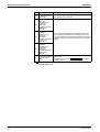
Connection Range for BS Unit
Components
Indoor unit total capacity
Note:
17
★
Outdoor unit model name
Total capacity of connectable indoor
units
Number of connectable indoor
units
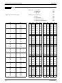
RQCEQ280PY1
14.0 to 36.4 (56.0)
16
RQCEQ360PY1
18.0 to 46.2 (72.0)
20
RQCEQ460PY1
23.0 to 59.8 (92.0)
26
RQCEQ500PY1
25.0 to 65.0 (100.0)
29
RQCEQ540PY1
27.0 to 70.2 (108.0)
33
RQCEQ636PY1
31.8 to 82.7 (127.2)
36
RQCEQ712PY1
35.6 to 92.6 (142.4)
40
RQCEQ744PY1
37.2 to 96.7 (148.8)
43
RQCEQ816PY1
40.8 to 106 (163.2)
47
RQCEQ848PY1
42.4 to 110 (169.6)
50
Values inside brackets are based on connection of indoor units rated at maximum capacity, 200% from single outdoor units, 160% from
double outdoor units, 130% from triple outdoor units.
Specifications
SiBE341001
Part 3
Refrigerant Circuit
1. Refrigerant Circuit .................................................................................19
1.1 RQYQ140 · 180PY1, RQEQ140 ~ 212PY1 ...........................................19
1.2 BS Unit ...................................................................................................21
2. Functional Parts Layout ........................................................................23
2.1 RQYQ140 · 180PY1, RQEQ140 ~ 212PY1............................................23
3. Refrigerant Flow for Each Operation Mode...........................................24
3.1 RQYQ140 · 180PY1 ...............................................................................24
3.2 RQCEQ280 ~ 848PY1 ...........................................................................27
Refrigerant Circuit
18
Refrigerant Circuit
SiBE341001
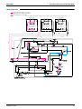
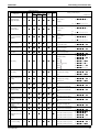
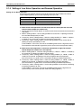
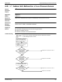
1. Refrigerant Circuit
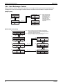
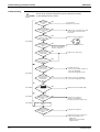
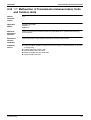
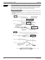
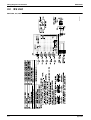
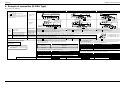
1.1
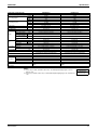
RQYQ140 · 180PY1, RQEQ140 ~ 212PY1
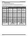
No. in
refrigerant Symbol
system
diagram
(1)
M1C
Inverter compressor (INV.)
(2)
M1F
Inverter fan
(3)
Y1E
(4)
Y2E
(5)
Y3E
(6)
Y1S
(7)
Y2S
(8)
Y3S
(9)
Y4S
(10)
Y5S
(11)
Y6S
(12)
Y7S
(13)
Y8S
(14)
Y9S
(15)
R1T
Electronic expansion valve
(Main)
Electronic expansion valve
(Refrigerant charge)
Electronic expansion valve
(Subcooling)
Solenoid valve (Refrigerant
regulator hot gas)
Solenoid valve (Refrigerant
regulator liquid pipe)
Solenoid valve (Refrigerant
regulator gas vent pipe)
Solenoid valve (Hot gas)
Solenoid valve (Circuit of oil
return)
Four way valve (Heat
exchanger)
Four way valve (Dual
pressure gas pipe)
Four way valve (Mixing unit)
Solenoid valve (Mixing unit
inlet)
Thermistor (Outdoor air: Ta)
(16)
R2T
Thermistor (Discharge pipe)
(17)
R3T
Thermistor (Heat exchanger
liquid pipe)
(18)
R4T
Thermistor (Heat exchanger
gas pipe)
(19)
R5T
(20)
R6T
Thermistor (Suction pipe)
Thermistor (Heat exchanger
deicer)
(21)
R7T
Thermistor (Subcooling heat
exchanger gas pipe)
(22)
(23)
(25)
(26)
19
Name
Thermistor (Subcooling heat
exchanger liquid pipe)
R9T
Thermistor (Liquid pipe)
S1NPH High pressure sensor
S1NPL Low pressure sensor
R8T
(27)
S1PH
High pressure switch (For
INV.)
(28)
—
Pressure regulating valve
(Liquid pipe)
(29)
—
Subcooling heat exchanger
(30)
—
Capillary tube
Major Function
Inverter compressor is operated on frequencies 52Hz to 210Hz (180 class: 248Hz, 212
class: 266Hz) by using the inverter. The number of operating steps is 20. (180 class:
23 steps, 212 class: 27 steps)
Because the system is an air heat exchange type, the fan is operated 8-step rotation
speed by using the inverter.
While in heating operation, PI control is applied to keep the outlet superheated degree
of air heat exchanger constant.
This is used to charge refrigerant and discharge refrigerant from the refrigerant
regulator.
PI control is applied to keep the outlet superheated degree of subcooling heat
exchanger constant.
Used to charge refrigerant and discharge refrigerant from the refrigerant regulator.
Used to collect refrigerant to the refrigerant regulator.
Used to collect refrigerant to the refrigerant regulator.
Used to prevent the low pressure from transient falling.
Used to adjust the amount of oil in the mixing unit.
Used to switch the operation mode between cooling and heating.
Used to switch dual pressure gas pipe to high pressure or low pressure.
Use to adjust the amount of refrigeration oil and clean pipes during check operation.
Use to adjust the amount of refrigeration oil and clean pipes during check operation.
Use to prevent refrigerant from flowing into the mixing unit during normal operation.
Used to detect outdoor temperature, correct discharge pipe temperature and others.
Used to detect discharge pipe temperature. Used for compressor temperature
protection control.
This detects temperature of liquid pipe between the air heat exchanger and main
electronic expansion valve. Used to make judgements on the recover or discharge
refrigerants to the refrigerant regulator.
This detects temperature of gas pipe for air heat exchanger. Used to exercise the
constant control of superheated degree when an evaporator is used for outdoor unit
heat exchanging.
Used to detect suction pipe temperature.
Used to detect liquid pipe temperature of air heat exchanger. Used to make
judgements on defrosting operation.
This detects temperature of gas pipe on the evaporation side of subcooling heat
exchanger. Used to exercise the constant control of superheated degree at the outlet
of subcooled heat exchanger.
This detects temperature of liquid pipe between the main electronic expansion valve
and subcooling heat exchanger.
This detects temperature of liquid pipe.
Used to detect high pressure.
Used to detect low pressure.
In order to prevent the increase of high pressure when a malfunction occurs, this
switch is activated at high pressure of 4.0 MPa or more to stop the compressor
operation.
Open at 3.3 MPa or more to avoid pressure increase to prevent damage to functional
parts by the pressure increase and to protect the field piping during transportation,
storage and operation of the equipment.
Apply subcooling to liquid refrigerant.
Used to return the refrigerating oil separated through the oil separator to the INV.
compressor.
Refrigerant Circuit
(14)
(23)
Refrigerant Circuit
(10)
(29)
(21)
(28)
(5)
(7)
(13)
(6)
(19)
(12)
(26)
(22)
(3)
(9)
(1)
(27)
(4)
(8)
(16)
(30)
(11)
(17)
(25)
(18)
Fan
M
(2)
(20)
(15)
SiBE341001
Refrigerant Circuit
3D066010A
20
Refrigerant Circuit
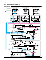
1.2
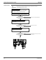
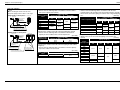
SiBE341001
BS Unit
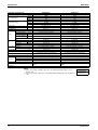
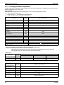
No.
Name
1
Electronic expansion valve (EVSC)
Symbol
Y1E
2
Electronic expansion valve (EVHS)
3
4
Electronic expansion valve (EVLS)
Electronic expansion valve (EVH)
5
6
Electronic expansion valve (EVL)
Capillary tube
7
Double pipe heat exchanger
Y2E
Y3E
Y4E
Y5E
—
—
Function
In simultaneous cooling and heating operation, it is used to subcooling
liquid refrigerants when an indoor unit downstream of this BS unit is in
heating operation.
Opens while in heating operation or all indoor units are in cooling
operation.
Opens while in cooling operation.
Opens while in heating operation or all indoor units are in cooling
operation.
Opens while in cooling operation.
Used to bypass high pressure gas to low pressure side to protect
“Refrigerant accumulation” in high and low pressure gas pipes.
In simultaneous cooling and heating operation, it is used to subcooling
liquid refrigerants when an indoor unit downstream of this BS unit is in
heating operation.
• BSVQ100 ~ 250PV1
(7)
(1)
(6)
(2)
(4)
(3)
(5)
4D057985B
21
Refrigerant Circuit
Refrigerant Circuit
(7)
(7)
(7)
(7)
(7)
(7)
(1)
(5)
(3)
(4)
(2)
(6)
(1)
(5)
(3)
(4)
(2)
(6)
(1)
(5)
(3)
(4)
(2)
(6)
(1)
(5)
(3)
(4)
(2)
(6)
(1)
(5)
(3)
(4)
(2)
(6)
(1)
(5)
(3)
(4)
(2)
(6)
(7)
(7)
(7)
(7)
(5)
(3)
(4)
(2)
(6)
(1)
(5)
(3)
(4)
(2)
(6)
(1)
(5)
(3)
(4)
(2)
(6)
(1)
(5)
(3)
(4)
(2)
(6)
(1)
SiBE341001
Refrigerant Circuit
• BSV4Q100PV1
3D064148
• BSV6Q100PV1
3D064149
22
Functional Parts Layout
SiBE341001
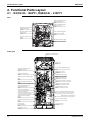
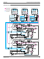
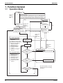
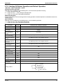
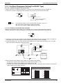
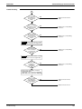
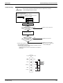
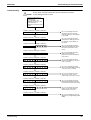
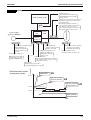
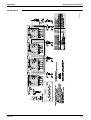
2. Functional Parts Layout
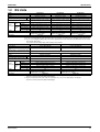
2.1
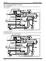
RQYQ140 · 180PY1, RQEQ140 ~ 212PY1
Plan
Solenoid valve (Refrigerant
regulator liquid pipe)
(Y2S)
Electronic expansion valve
(Refrigerant charge)
(Y2E)
Electronic expansion valve
(Subcooling)
(Y3E)
Solenoid valve (Refrigerant
regulator hot gas)
(Y1S)
Solenoid valve (Refrigerant
regulator gas vent pipe)
(Y3S)
Electronic expansion valve
(Main)
(Y1E)
Thermistor (Discharge pipe)
(R2T)
Front View
Four way valve (Mixing unit)
(Y8S)
Inverter fan
(M1F)
Thermistor (Subcooling heat
exchanger gas pipe)
(R7T)
Thermistor (Liquid pipe)
(R9T)
Thermistor (Heat exchanger liquid
pipe)
(R3T)
Thermistor (Heat exchanger gas
pipe)
(R4T)
Thermistor (Subcooling heat
exchanger liquid pipe)
(R8T)
Solenoid valve (Mixing unit inlet)
(Y9S)
High pressure sensor
(S1NPH)
Thermistor (Suction pipe)
(R5T)
Solenoid valve (Hot gas)
(Y4S)
Solenoid valve (Circuit of oil return)
(Y5S)
High pressure switch (For INV.)
(S1PH)
Thermistor (Outdoor air: Ta)
(R1T)
Service port (Liquid pipe)
Service port (Gas pipe)
Service port (Suction gas pipe)
Thermistor (Heat exchanger
deicer)
(R6T)
Four way valve (Dual pressure gas
pipe)
(Y7S)
Four way valve
(Heat exchanger)
(Y6S)
Service port (Air tight and vacuum drying)
Service port · Charge at check operation
· Air tight and vacuum drying
Inverter compressor (INV.)
(M1C)
Crankcase heater
(E1HC)
Low pressure sensor
(S1NPL)
23
Refrigerant Circuit
SiBE341001
Refrigerant Flow for Each Operation Mode
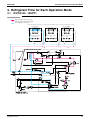
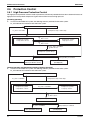
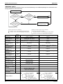
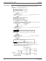
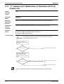
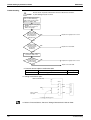
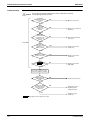
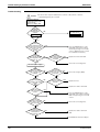
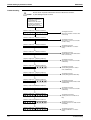
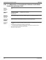
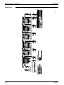
3. Refrigerant Flow for Each Operation Mode
3.1
RQYQ140 · 180PY1
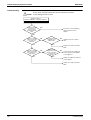
Cooling operation
"High temperature, high pressure gas"
"High temperature, high pressure liquid"
"Low temperature, low pressure"
Indoor unit
Indoor unit operation "ON" (Cooling)
+
Thermostat "ON"
Heat exchanger
Indoor unit operation "OFF" (Cooling)
Indoor unit operation "ON" (Cooling)
+
Thermostat "OFF"
Heat exchanger
Heat exchanger
Fan "ON"
Fan "OFF"
Fan "ON"
Electronic expansion valve
(Superheated control)
Electronic expansion valve
(0 pls)
Electronic expansion valve
(0 pls)
Filter
Filter
Filter
Filter
Filter
Filter
Fan
M
Refrigerant Circuit
24
Refrigerant Flow for Each Operation Mode
SiBE341001
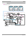
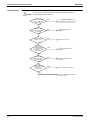
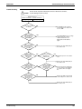
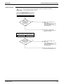
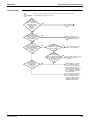
Cooling oil return / Heating oil return / Defrost operation
"High temperature, high pressure gas"
"High temperature, high pressure liquid"
"Low temperature, low pressure"
Indoor unit
Indoor unit operation "ON" (Cooling)
+
Thermostat "ON"
Heat exchanger
Indoor unit operation "OFF" (Cooling)
Heat exchanger
Indoor unit operation "ON" (Cooling)
+
Thermostat "OFF"
Heat exchanger
Fan "ON"
Fan "OFF"
Fan "ON"
Electronic expansion valve
(Superheated control)
Electronic expansion valve
(224 pls)
Electronic expansion valve
(224 pls)
Filter
Filter
Filter
Filter
Filter
Filter
Fan
M
25
Refrigerant Circuit
SiBE341001
Refrigerant Flow for Each Operation Mode
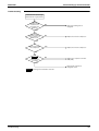
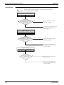
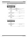
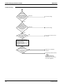
Heating operation
"High temperature, high pressure gas"
"High temperature, high pressure liquid"
"Low temperature, low pressure"
Indoor unit
Indoor unit operation "ON" (Heating)
+
Thermostat "ON"
Indoor unit operation "OFF" (Heating)
Indoor unit operation "ON" (Heating)
+
Thermostat "OFF"
Heat exchanger
Heat exchanger
Heat exchanger
Fan "ON"
Fan "OFF"
Fan "OFF"
Electronic expansion valve
(Superheated control)
Electronic expansion valve
(200 ~ 300 pls)
Electronic expansion valve
(200 ~ 300 pls)
Filter
Filter
Filter
Filter
Filter
Filter
Fan
M
Refrigerant Circuit
26
Refrigerant Flow for Each Operation Mode
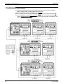
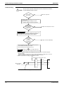
3.2
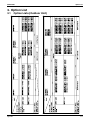
SiBE341001
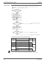
RQCEQ280 ~ 848PY1
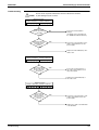
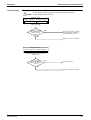
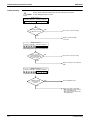
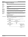
Cooling operation
Indoor unit operation "ON" (Cooling)
+
Thermostat "ON"
Indoor unit
"High temperature,
high pressure gas"
"High temperature,
high pressure liquid"
"Low temperature,
low pressure"
Indoor unit operation "ON" (Cooling)
+
Thermostat "OFF"
Indoor unit operation "OFF" (Cooling)
Heat exchanger
Heat exchanger
Heat exchanger
Fan "ON"
(Setting)
Fan "ON"
(Setting)
Fan "OFF"
Filter Electronic expansion valve Filter
(Normal)
Filter Electronic expansion valve Filter
(0 pls)
Filter Electronic expansion valve Filter
(0 pls)
Fan
M
Fan
M
27
Refrigerant Circuit
SiBE341001
Refrigerant Flow for Each Operation Mode
Cooling oil return operation
Indoor unit operation "ON" (Cooling)
+
Thermostat "ON"
Indoor unit
"High temperature,
high pressure gas"
"High temperature,
high pressure liquid"
"Low temperature,
low pressure"
Indoor unit operation "ON" (Cooling)
+
Thermostat "OFF"
Indoor unit operation "OFF" (Cooling)
Heat exchanger
Heat exchanger
Heat exchanger
Fan "ON"
(Setting)
Fan "ON"
(Setting)
Fan "OFF"
Filter Electronic expansion valve Filter
(Normal)
Filter Electronic expansion valve Filter
(Forced thermo "ON")
Filter Electronic expansion valve Filter
(192 pls)
Fan
M
Fan
M
Refrigerant Circuit
28
Refrigerant Flow for Each Operation Mode
SiBE341001
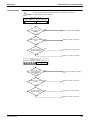
Heating operation
Indoor unit operation "ON" (Heating)
+
Thermostat "ON"
Indoor unit
"High temperature,
high pressure gas"
"High temperature,
high pressure liquid"
"Low temperature,
low pressure"
Indoor unit operation "ON" (Heating)
+
Thermostat "OFF"
Indoor unit operation "OFF" (Heating)
Heat exchanger
Heat exchanger
Heat exchanger
Fan "ON"
(Setting)
Fan "ON"
(Setting)
Fan "OFF"
Filter Electronic expansion valve Filter
(Normal)
Filter Electronic expansion valve Filter
(192 pls)
Filter Electronic expansion valve Filter
(192 pls)
Fan
M
Fan
M
29
Refrigerant Circuit
SiBE341001
Refrigerant Flow for Each Operation Mode
Heating oil return operation
Indoor unit operation "ON" (Heating)
+
Thermostat "ON"
Indoor unit
"High temperature,
high pressure gas"
"High temperature,
high pressure liquid"
"Low temperature,
low pressure"
Indoor unit operation "ON" (Heating)
+
Thermostat "OFF"
Indoor unit operation "OFF" (Heating)
Heat exchanger
Heat exchanger
Heat exchanger
Fan "ON"
(Setting)
Fan "ON"
(Setting)
Fan "OFF"
Filter Electronic expansion valve Filter
(Normal)
Filter Electronic expansion valve Filter
(Forced thermo "ON")
Filter Electronic expansion valve Filter
(192 pls)
Fan
M
Fan
M
Refrigerant Circuit
30
Refrigerant Flow for Each Operation Mode
SiBE341001
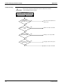
Defrost 1 operation
Indoor unit operation "ON" (Heating)
+
Thermostat "ON"
Indoor unit
"High temperature,
high pressure gas"
"High temperature,
high pressure liquid"
"Low temperature,
low pressure"
Indoor unit operation "ON" (Heating)
+
Thermostat "OFF"
Indoor unit operation "ON" (Cooling)
Heat exchanger
Heat exchanger
Heat exchanger
Fan "OFF"
Fan "OFF"
Fan "ON"
(Setting)
Filter Electronic expansion valve Filter
(0 pls)
Filter Electronic expansion valve Filter
(0 pls)
Filter Electronic expansion valve Filter
(Normal)
Fan
M
Fan
M
31
Refrigerant Circuit
SiBE341001
Refrigerant Flow for Each Operation Mode
Defrost 2 operation
Indoor unit operation "ON" (Heating)
+
Thermostat "ON"
Indoor unit
"High temperature,
high pressure gas"
"High temperature,
high pressure liquid"
"Low temperature,
low pressure"
Indoor unit operation "ON" (Heating)
+
Thermostat "OFF"
Indoor unit operation "ON" (Cooling)
Heat exchanger
Heat exchanger
Heat exchanger
Fan "OFF"
Fan "OFF"
Fan "OFF"
Filter Electronic expansion valve Filter
(0 pls)
Filter Electronic expansion valve Filter
(0 pls)
Filter Electronic expansion valve Filter
(Normal)
Fan
M
Fan
M
Refrigerant Circuit
32
Refrigerant Flow for Each Operation Mode
SiBE341001
Simultaneous cooling / Heating operation
Indoor unit operation "ON" (Cooling)
+
Thermostat "ON"
Indoor unit
"High temperature,
high pressure gas"
"High temperature,
high pressure liquid"
"Low temperature,
low pressure"
Indoor unit operation "ON" (Heating)
+
Thermostat "ON"
Indoor unit operation "ON" (Heating)
+
Thermostat "ON"
Heat exchanger
Heat exchanger
Heat exchanger
Fan "ON"
(Setting)
Fan "ON"
(Setting)
Fan "ON"
(Setting)
Filter Electronic expansion valve Filter
(Normal)
Filter Electronic expansion valve Filter
(Normal)
Filter Electronic expansion valve Filter
(Normal)
Fan
M
Fan
M
33
Refrigerant Circuit
SiBE341001
Part 4
Function
1. Function General...................................................................................35
1.1 Operation Mode......................................................................................35
1.2 Symbol ...................................................................................................36
2. Detailed Control Functions....................................................................37
2.1
2.2
2.3
2.4
2.5
2.6
2.7
Function
Stop Operation .......................................................................................37
Standby ..................................................................................................37
Rotation Control .....................................................................................37
Startup Control .......................................................................................38
Normal Operation ...................................................................................39
Protection Control...................................................................................47
Special Control .......................................................................................52
34
Function General
SiBE341001
1. Function General
1.1
Operation Mode
2-1. Stop
operation
Thermostat ON
(If test run has not been completed, the error code "U3" is displayed and the
unit will not operation. However this does not apply to test run operation in
service mode, refrigerant charging operation, and pump-down operation.)
Indoor unit
stop or
thermostat
OFF
2.2. Standby
(1)
Restart Standby
(2)
Crankcase
Heater Control
Retry
Pressure
equalization prior
to startup
Indoor unit
stop or
thermostat
OFF
2.4. Startup control
Startup control
[Cooling startup control,
* Heating startup control]
Retry
Indoor unit thermostat ON
Indoor unit
stop or
thermostat
OFF
2.5. Normal Operation
(1) List of Functions in Normal 2.3. Outdoor Unit
Operation
Rotation
(2) Compressor PI Control
(3) Compressor Step Control
(4) Electronic Expansion
Valve PI Control
In Operation
(5) Step Control of
Outdoor Unit Fans
(6) Heat Exchanger
Control
(7) Control of Refrigerant
Amount
Oil return IN
conditions are
met
2.6. Protection Control
(1) High Pressure
Protection Control
(2) Low Pressure
Protection Control
(3) Discharge Pipe
Protection Control
(4) Inverter Protection
Control
Pump-down
Residual
Operation
Indoor unit
stop or
thermostat
OFF
Retry
2.7. Special Control
Yes
(1) Oil return Operation
No
Defrost IN
conditions are
met *
Yes
(2) Defrost Operation *
No
Cooling / Heating
change *
Yes
* This function does not used
because there is no heating
operation.
No
35
Function
SiBE341001
1.2
Function General
Symbol
Symbol
Electric symbol
20SA
Y6S
Y7S
Four way valve (Heat exchanger switch)
Four way valve (Dual pressure gas pipe switch)
DSH
Y8S
—
Four way valve (Mixing unit)
Discharge pipe superheated degree
DSHi
DSHs
—
—
EV
EVJ
—
Y2E
Opening of electronic expansion valve
Electronic expansion valve (Refrigerant charge)
EVM
EVT
Y1E
Y3E
Electronic expansion valve (Main)
Electronic expansion valve (Subcooling)
HTdi
—
HTds
—
Pc
Pe
S1NPH
S2NPL
SH
SHS
—
—
Evaporator outlet superheated degree
Target evaporator outlet superheated degree
SVB
SVG1
Y5S
Y1S
Solenoid valve (Circuit of oil return)
Solenoid valve (Refrigerant regulator hot gas)
SVG2
SVL
Y3S
Y2S
Solenoid valve (Refrigerant regulator gas vent pipe)
Solenoid valve (Refrigerant regulator liquid pipe)
SVP
Ta
Y4S
R1T
Solenoid valve (Hot gas)
Outdoor air temperature
Tb
Tc
R4T
—
Heat exchanger outlet temperature at cooling
High pressure equivalent saturation temperature
TcS
Tdi
—
R31T
Target temperature of Tc
Discharge pipe temperature of INV. compressor
Tds
Te
R32T, R33T
—
Discharge pipe temperature of STD compressor
Low pressure equivalent saturation temperature
TeS
—
Tf
R7T
Tfin
Tg
R1T (A3P)
R4T
TI
R6T
TsA
R5T
Temperature of liquid pipe between main electronic expansion valve and subcooling heat
exchanger
Suction pipe temperature
Tsc
Tsh
R9T
R5T
Temperature of liquid pipe
Temperature of gas pipe detected with the subcooling heat exchanger outlet thermistor
20SB
Function
Description of function
Discharge pipe superheated degree of INV. compressor
Discharge pipe superheated degree of STD compressor
Value of INV. compressor discharge pipe temperature compensated with outdoor air
temperature
Value of STD compressor discharge pipe temperature compensated with outdoor air
temperature
Value detected by high pressure sensor
Value detected by low pressure sensor
Target temperature of Te
Temperature of liquid pipe between outdoor unit heat exchanger and main electronic
expansion valve
Inverter fin temperature
Heat exchanger gas pipe temperature
36
Detailed Control Functions
SiBE341001
2. Detailed Control Functions
2.1
Stop Operation
2.1.1 Stop due to Malfunction
In order to protect compressors, if any of the abnormal state occurs, the system will make "stop with thermostat OFF"
and the malfunction will be determined according to the number of retry times.
(Refer to "Malfunction code list" (P.107~) of the troubleshooting for the items to determine the malfunction.)
∗ Operation to determine the malfunction: "Stop the system" and "malfunction code" is displayed on the remote
controller.
2.1.2 When System is in Stop Mode
Stop both the master and slave units.
The four way valves both for heat exchanger switch and piping switch retain the condition before they were stopped.
2.2
Standby
2.2.1 Restart Standby
Used to forcedly stop the compressor for a period of 3 minutes, in order to prevent the frequent ON/OFF of the
compressor and equalize the pressure within the refrigerant system.
In addition, the outdoor fan carry out the residual operation for a while to suppress the acceleration of the pressure
equalizing and melting of the refrigerant to the evaporator.
2.2.2 Crankcase Heater Control
In order to prevent the refrigerant from melting in the compressor oil in the stopped mode, this mode is used to control
the crankcase heater.
Discharge pipe
temperature < 70˚C
Crankcase heater
OFF
2.3
Discharge pipe
temperature > 75˚C
Crankcase heater
ON
Rotation Control
2.3.1 Outdoor Unit Rotation
In the case of multi-outdoor-unit system, this outdoor unit rotation is used to prevent the compressor from burning out
due to unbalanced oil level between outdoor units.
[Timing of outdoor unit rotation]
· At the beginning of startup control
<System with two outdoor units>
Outdoor Unit 1
Outdoor Unit 2
Previous time
This time
Priority 1
Priority 2
Priority 2
Priority 1
Next time
Priority 1
Priority 2
<System with three outdoor units>
Previous time
Outdoor Unit 1
Priority 1
Outdoor Unit 2
Priority 2
Outdoor Unit 3
Priority 3
This time
Next time
Priority 3
Priority 2
Priority 1
Priority 3
Priority 2
Priority 1
One time after the next
Priority 1
Priority 2
Priority 3
<System with four outdoor units>
Outdoor Unit 1
Outdoor Unit 2
Outdoor Unit 3
Outdoor Unit 3
Previous time
This time
Priority 1
Priority 4
Priority 2
Priority 1
Priority 3
Priority 2
Priority 4
Priority 3
Next time
One time after the next
Priority 3
Priority 2
Priority 4
Priority 3
Priority 1
Priority 4
Priority 2
Priority 1
One time after the
next plus one
Priority 1
Priority 2
Priority 3
Priority 4
37
Function
SiBE341001
2.4
Detailed Control Functions
Startup Control
This control is used to equalize the pressure in the front and back of the compressor prior to the startup of the
compressor, thus reducing startup loads. Furthermore, the inverter is turned ON to charge the capacitor.
To avoid stresses to the compressor due to oil return or else after the startup, the following control is made and the
position of the four way valve is also determined. Start both the master and the slave units simultaneously to position
the four way valve.
(1) Startup Control in Cooling Operation
[Ending conditions]
+4 → +7 → +5 Step / 20 sec.
OR
52 Hz
Inverter compressor (INV.) 0 Hz
(M1C)
· A lapse of 90 sec.
· Tc (high pressure equivalent
saturation temperature) > 48˚C
· Pc-Pe > 0.39MPa.
1375 pls
Electronic expansion valve 0 pls
(Y1E: Main)
Inverter fan
(M1F)
Step 4
Ta < 20˚C : OFF
Ta ≥ 20˚C : Step 4
+1 Step / 15 sec. (when Pc > 2.16 MPa)
-1 Step / 15 sec. (when Pc < 1.77 MPa)
Thermo. ON: Initial opening
0 pls
Indoor unit electronic
expansion valve
(Y1E)
15 sec.
(2) Startup Control in Heating Operation (Outdoor unit heat exchanger = Evaporator)
[Ending conditions]
+4 → +7 → +5 Step / 20 sec.
OR
· A lapse of 90 sec.
· Pc-Pe > 0.39MPa.
52 Hz
Inverter compressor (INV.) 0 Hz
(M1C)
Initial opening
Electronic expansion valve 0 pls
(Y1E: Main)
Inverter fan
(M1F)
Step 8
Step 4
ON
OFF
Four way valve
(Y3S)
15 sec.
(3) Startup Control in Heating Operation (Outdoor unit heat exchanger = Condenser)
[Ending conditions]
+4 → +7 → +5 Step / 20 sec.
OR
· A lapse of 90 sec.
· Pc-Pe > 0.39MPa.
52 Hz
Inverter compressor (INV.) 0 Hz
(M1C)
Electronic expansion valve 0 pls
(Y1E: Main)
Inverter fan
(M1F)
1375 pls
+1 Step / 15 sec. (when Pc > 2.16 MPa)
-1 Step / 15 sec. (when Pc < 1.77 MPa)
Step 4
OFF
Four way valve
(Y3S)
Function
OFF
15 sec.
38
Detailed Control Functions
2.5
SiBE341001
Normal Operation
2.5.1 List of Functions in Normal Operation
<Outdoor Unit>
Electric
Symbol
Normal Cooling
Normal Heating
Compressor
M1C
PI control, High pressure
protection, Low pressure
protection, Td protection,
INV protection
Outdoor unit fan
M1F
Cooling fan control
Electronic expansion valve
(Main)
Y1E
480 pls
PI control, High pressure
protection, Low pressure
protection, Td protection,
INV protection
• Outdoor unit heat
exchanger: Condenser /
Cooling fan control
• Outdoor unit heat
exchanger: Evaporator /
Fan step 7 or 8
• Outdoor unit heat
exchanger: Condenser /
Liquid pressure control
• Outdoor unit heat
exchanger: Evaporator /
PI control
Normal Simultaneous
Cooling / Heating
PI control, High pressure
protection, Low pressure
protection, Td protection,
INV protection
• Outdoor unit heat
exchanger: Condenser /
Cooling fan control
• Outdoor unit heat
exchanger: Evaporator /
Fan step 7 or 8
• Outdoor unit heat
exchanger: Condenser /
Liquid pressure control
• Outdoor unit heat
exchanger: Evaporator /
PI control
Y3E
PI control
PI control
PI control
Y2E
Y4S
41 pls for refrigerant
discharge
ON for refrigerant
discharge
ON for refrigerant
recovery
ON for refrigerant
recovery
OFF
41 pls for refrigerant
discharge
ON for refrigerant
discharge
ON for refrigerant
recovery
ON for refrigerant
recovery
OFF
41 pls for refrigerant
discharge
ON for refrigerant
discharge
ON for refrigerant
recovery
ON for refrigerant
recovery
OFF
Y5S
ON
ON
ON
Part Name
Electronic expansion valve
(Subcooling)
Electronic expansion valve
(Refrigerant charge)
Solenoid valve (Refrigerant
regulator hot gas)
Solenoid valve (Refrigerant
regulator liquid pipe)
Solenoid valve (Refrigerant
regulator gas vent pipe)
Solenoid valve (Hot gas)
Solenoid valve (Circuit of oil
return)
Y1S
Y2S
Y3S
• Outdoor unit heat
• Outdoor unit heat
exchanger: Condenser /
exchanger: Condenser /
OFF
OFF
• Outdoor unit heat
• Outdoor unit heat
exchanger: Evaporator /
exchanger: Evaporator /
ON
ON
Four way valve (Heat
exchanger switch)
Y6S
OFF
Four way valve (Dual
pressure gas pipe)
Four way valve (Mixing unit)
Solenoid valve (Mixing unit
inlet)
Y7S
ON
OFF
OFF
Y8S
OFF
OFF
OFF
Y9S
OFF
OFF
OFF
<Indoor Unit>
Part Name
Electric
Symbol
Indoor unit fan
M1F
Electronic expansion valve
(Main)
Y1E
Thermostat
ON unit
Remote
controller
setting
Normal
opening
Normal cooling
Thermostat
Stopping
OFF unit
unit
Remote
controller
OFF
setting
0 pls
0 pls
Thermostat
ON unit
Remote
controller
setting
Normal
opening
Normal heating
Thermostat
Stopping
OFF unit
unit
LL
OFF
192 pls
192 pls
<BS Unit>
Part Name
Electronic expansion valve
(EVSC)
Electronic expansion valve
(EVHS)
Electronic expansion valve
(EVLS)
Electronic expansion valve
(EVH)
Electronic expansion valve
(EVL)
39
Electric
Symbol
Normal cooling
Normal heating
Y1E
0 pls
0 pls
Y2E
480 pls ( fully opened )
480 pls ( fully opened )
Y3E
480 pls ( fully opened )
0 pls
Y4E
760 pls ( fully opened )
760 pls ( fully opened )
Y5E
760 pls ( fully opened )
0 pls
Function
SiBE341001
Detailed Control Functions
2.5.2 Compressor PI Control
Carries out the compressor capacity PI control to maintain Te at constant during cooling operation and Tc at constant
during heating operation to ensure stable unit performance.
[Cooling operation]
Controls compressor capacity to adjust Te to achieve target value (TeS).
Te set value (Make this setting while in Setting mode 2.)
Te setting
L
3ºC
M (Normal)
(factory setting)
6ºC
H
7ºC
8ºC
9ºC
10ºC
11ºC
Te : Low pressure equivalent saturation temperature (°C)
TeS : Target temperature of Te (Varies depending on Te setting, operating frequency, etc.)
* On multi-outdoor-unit systems, this control is made according to values of the first-priority unit, which is detected with
the pressure sensor.
[Heating operation]
Controls compressor capacity to adjust Tc to achieve target value (TcS).
Tc set value (Make this setting while in Setting mode 2.)
Tc setting
L
43ºC
M (Normal)
(factory setting)
46ºC
H
47ºC
Tc : High pressure equivalent saturation temperature (°C)
TcS : Target temperature of Tc (Varies depending on Tc setting, operating frequency, etc.)
* On multi-outdoor-unit systems, this control is made according to values of the first-priority unit, which is detected with
the pressure sensor.
Function
40
Detailed Control Functions
SiBE341001
2.5.3 Compressor Step Control
Compressor operations vary with the following steps according to information in “2.5.2 Compressor PI Control”.
RQYQ140 · 180PY1
STEP INV.
No.
Initial step
RQCYQ280 · 360PY1
RQCEQ280 · 360PY1
STEP Master Slave
No. INV. INV.
1
52Hz
2
56Hz
1
52Hz OFF
3
62Hz
2
56Hz OFF
4
68Hz
3
62Hz OFF
5
74Hz
4
68Hz OFF
6
80Hz
5
74Hz OFF
7
88Hz
6
80Hz OFF
8
96Hz
7
88Hz OFF
9
104Hz
8
96Hz OFF
10
110Hz
9
104Hz OFF
1
52Hz 52Hz
11
116Hz
10
110Hz OFF
2
56Hz 56Hz
12
124Hz
11
116Hz OFF
3
62Hz 62Hz
13
132Hz
12
124Hz OFF
4
66Hz 66Hz
14
144Hz
13
132Hz OFF
5
70Hz 70Hz
15
158Hz
14
144Hz OFF
6
74Hz 74Hz
16
166Hz
7
80Hz 80Hz
17
176Hz
8
88Hz 88Hz
18
188Hz
9
92Hz 92Hz
19
202Hz
10
96Hz 96Hz
20
210Hz ∗1
11
104Hz 104Hz
21
218Hz
12
110Hz 110Hz
22
232Hz
13
116Hz 116Hz
23
248Hz ∗2
14
124Hz 124Hz
15
132Hz 132Hz
16
144Hz 144Hz
17
158Hz 158Hz
18
166Hz 166Hz
19
176Hz 176Hz
20
188Hz 188Hz
21
202Hz 202Hz
∗1: Upper limit of Q140 type is 20.
∗2: Upper limit of Q180 type is 23.
41
22
210Hz 210Hz ∗1
23
218Hz 218Hz
∗1: Upper limit of Q140
24
232Hz 232Hz
type is 22.
∗2: Upper limit of Q180
type is 25.
25
248Hz 248Hz ∗2
Initial step
Function
SiBE341001
Detailed Control Functions
RQCYQ460 ~ 540PY1
RQCEQ460 ~ 636PY1
STEP Master Slave 1 Slave 2
No. INV. INV. INV.
1
52Hz OFF
OFF
2
56Hz OFF
OFF
3
62Hz OFF
OFF
4
68Hz OFF
OFF
5
74Hz OFF
OFF
6
80Hz OFF
OFF
7
88Hz OFF
OFF
8
96Hz OFF
OFF
9
104Hz OFF
OFF
1
52Hz 52Hz OFF
10
110Hz OFF
OFF
2
56Hz 56Hz OFF
11
116Hz OFF
OFF
3
62Hz 62Hz OFF
12
124Hz OFF
OFF
4
66Hz 66Hz OFF
13
132Hz OFF
OFF
5
70Hz 70Hz OFF
14
144Hz OFF
OFF
6
74Hz 74Hz OFF
1
52Hz 52Hz 52Hz
7
80Hz 80Hz OFF
2
56Hz 56Hz 56Hz
8
88Hz 88Hz OFF
3
62Hz 62Hz 62Hz
9
92Hz 92Hz OFF
4
66Hz 66Hz 66Hz
10
96Hz 96Hz OFF
5
68Hz 68Hz 68Hz
11
104Hz 104Hz OFF
6
70Hz 70Hz 70Hz
12
110Hz 110Hz OFF
7
74Hz 74Hz 74Hz
13
116Hz 116Hz OFF
8
80Hz 80Hz 80Hz
9
88Hz 88Hz 88Hz
∗1: Upper limit of Q140 type is 23.
∗2: Upper limit of Q180 type is 26.
∗3: Upper limit of Q212 type is 27.
Function
10
96Hz 96Hz 96Hz
11
104Hz 104Hz 104Hz
12
110Hz 110Hz 110Hz
13
116Hz 116Hz 116Hz
14
124Hz 124Hz 124Hz
15
132Hz 132Hz 132Hz
16
138Hz 138Hz 138Hz
17
144Hz 144Hz 144Hz
18
158Hz 158Hz 158Hz
19
166Hz 166Hz 166Hz
20
176Hz 176Hz 176Hz
21
188Hz 188Hz 188Hz
22
202Hz 202Hz 202Hz
23
210Hz 210Hz 210Hz ∗1
24
218Hz 218Hz 218Hz
25
232Hz 232Hz 232Hz
26
248Hz 248Hz 248Hz ∗2
27
266Hz 266Hz 266Hz ∗3
Initial step
42
Detailed Control Functions
SiBE341001
RQCEQ712 ~ 848PY1
STEP Master Slave 1 Slave 2 Slave 3
No. INV. INV. INV. INV.
1
52Hz OFF
OFF
OFF
2
56Hz OFF
OFF
OFF
3
62Hz OFF
OFF
OFF
4
68Hz OFF
OFF
OFF
5
74Hz OFF
OFF
OFF
6
80Hz OFF
OFF
OFF
7
88Hz OFF
OFF
OFF
8
96Hz OFF
OFF
OFF
9
104Hz OFF
OFF
OFF
1
52Hz 52Hz OFF
OFF
10
110Hz OFF
OFF
OFF
2
56Hz 56Hz OFF
OFF
11
116Hz OFF
OFF
OFF
3
62Hz 62Hz OFF
OFF
12
124Hz OFF
OFF
OFF
4
66Hz 66Hz OFF
OFF
13
132Hz OFF
OFF
OFF
5
70Hz 70Hz OFF
OFF
14
144Hz OFF
OFF
OFF
6
74Hz 74Hz OFF
OFF
1
52Hz 52Hz 52Hz OFF
7
80Hz 80Hz OFF
OFF
2
56Hz 56Hz 56Hz OFF
8
88Hz 88Hz OFF
OFF
3
62Hz 62Hz 62Hz OFF
9
92Hz 92Hz OFF
OFF
4
66Hz 66Hz 66Hz OFF
10
96Hz 96Hz OFF
OFF
5
68Hz 68Hz 68Hz OFF
1
52Hz 52Hz 52Hz 52Hz
11
104Hz 104Hz OFF
OFF
6
70Hz 70Hz 70Hz OFF
2
56Hz 56Hz 56Hz 56Hz
12
110Hz 110Hz OFF
OFF
7
74Hz 74Hz 74Hz OFF
3
62Hz 62Hz 62Hz 62Hz
13
116Hz 116Hz OFF
OFF
8
80Hz 80Hz 80Hz OFF
4
66Hz 66Hz 66Hz 66Hz
9
88Hz 88Hz 88Hz OFF
5
68Hz 68Hz 68Hz 68Hz
10
96Hz 96Hz 96Hz OFF
6
70Hz 70Hz 70Hz 70Hz
11
104Hz 104Hz 104Hz OFF
7
74Hz 74Hz 74Hz 74Hz
12
110Hz 110Hz 110Hz OFF
8
80Hz 80Hz 80Hz 80Hz
13
116Hz 116Hz 116Hz OFF
9
88Hz 88Hz 88Hz 88Hz
14
124Hz 124Hz 124Hz OFF
10
96Hz 96Hz 96Hz 96Hz
11
104Hz 104Hz 104Hz 104Hz
12
110Hz 110Hz 110Hz 110Hz
13
116Hz 116Hz 116Hz 116Hz
14
124Hz 124Hz 124Hz 124Hz
15
132Hz 132Hz 132Hz 132Hz
16
138Hz 138Hz 138Hz 138Hz
17
144Hz 144Hz 144Hz 144Hz
18
158Hz 158Hz 158Hz 158Hz
19
166Hz 166Hz 166Hz 166Hz
20
176Hz 176Hz 176Hz 176Hz
21
188Hz 188Hz 188Hz 188Hz
22
202Hz 202Hz 202Hz 202Hz
∗1: Upper limit of Q140 type is 23.
∗2: Upper limit of Q180 type is 26.
∗3: Upper limit of Q212 type is 27.
43
23
210Hz 210Hz 210Hz 210Hz ∗1
24
218Hz 218Hz 218Hz 218Hz
25
232Hz 232Hz 232Hz 232Hz
26
248Hz 248Hz 248Hz 248Hz ∗2
27
266Hz 266Hz 266Hz 266Hz ∗3
Initial step
Function
SiBE341001
Detailed Control Functions
2.5.4 Electronic Expansion Valve PI Control
Main electronic expansion valve EVM control
When the outdoor unit heat exchanging is performed via the evaporator (20SA is set to ON),
this function is used to exert PI control on the electronic expansion valve (Y1E) so that the
evaporator outlet superheated degree (SH) will become constant.
SH = Tg - Te
SH: Evaporator outlet superheated degree
(°C)
Tg : Suction pipe temperature (°C) detected
by the heat exchanger gas pipe
thermistor R4T.
Te : Low pressure equivalent saturation
temperature (°C)
Subcooling electronic expansion valve EVT control
In order to make the maximum use of the subcooling heat exchanger, this function is used to
exert PI control on the electronic expansion valve (Y3E) so that the evaporator-side gas pipe
superheated degree (SH) will become constant.
SH = Tsh - Te
SH: Outlet superheated degree of evaporator
(°C)
Tsh: Suction pipe temperature (°C) detected
by the subcooling heat exchanger outlet
thermistor R7T
Te: Low pressure equivalent saturation
temperature (°C)
Refrigerant charge electronic expansion valve EVJ control
While in automatic refrigerant charge mode or additional refrigerant charge mode, this function
is used to exert PI control on the opening degree of the electronic expansion valve (Y2E) in
response to outdoor temperature and close the valve after the completion of refrigerant charge.
For normal operation, this electronic expansion valve is set to “41 pls”.
2.5.5 Step Control of Outdoor Unit Fans
[Step control of fans]
Used to control the revolutions of outdoor unit fans in the steps listed in table below, according to condition changes.
Fan revolutions (rpm)
STEP No.
RQYQ180PY1
RQEQ180PY1
285
RQEQ212PY1
1
RQYQ140PY1
RQEQ140PY1
285
2
3
315
360
315
360
315
360
4
5
450
570
450
570
450
570
6
7
710
830
710
855
710
855
8
Cooling: 951
Heating: 941
1100
1100
285
* Figures listed above are all those controlled while in standard mode, which vary when the system is set to high static
pressure or capacity precedence mode.
[Control at a low outdoor temperature during cooling]
Secure the liquid pressure and circulating rate in the indoor unit through high pressure control with the outdoor fan when
the outdoor temperature is low during cooling. Control the fan with the target Tc (high pressure equivalent saturation
temperature) = 34°C
Function
44
Detailed Control Functions
SiBE341001
2.5.6 Heat Exchanger Control
While in heating or cool/heat simultaneous operation, ensure target condensing and evaporating temperature by
changing over the air heat exchanger of outdoor unit to the evaporator or the condenser in response to loads.
[Single system]
Outdoor unit
Left side
Note 1. "GR" is a numeric value
representing the current
balanced condition and
calculated from target
–
Evaporator
condensing temperature,
target evaporating
temperature, current
GR > 15
GR < -10
condensing temperature,
and current evaporating
Outdoor unit
temperature.
Outdoor unit
Right side
Condenser Condenser
GR > 25
GR < -20
Outdoor unit
Left side
GR > 25
Right side
GR < -20
Evaporator Condenser
Left side
Right side
Left side
Right side
Evaporator Evaporator
[Multi outdoor unit system]
A1
Outdoor unit
1
2
3
Condenser Condenser Condenser
GR > 15
A2
Note 1. "GR" is a numeric value representing the current balanced
condition and calculated from target condensing temperature,
target evaporating temperature, current condensing temperature,
and current evaporating temperature.
Note 2. On the system with two outdoor units, if there is no step for the
destination of transition, that step will be skipped.
GR < -10
Outdoor unit
1
2
B1
3
Condenser Condenser Evaporator
GR > 25
A3
2
GR > 15
GR > 25
–
2
3
Condenser Evaporator Evaporator
45
–
B2
GR < -20
GR < -10
Outdoor unit
1
2
GR > 15
GR > 25
3
Evaporator Evaporator
GR < -10
Outdoor unit
1
3
Evaporator
GR > 15
3
Condenser Evaporator
A4
2
–
GR < -20
Outdoor unit
1
Outdoor unit
1
–
GR < -10
Outdoor unit
B3
1
2
3
Evaporator Evaporator Evaporator
Function
SiBE341001
Detailed Control Functions
2.5.7 Control of Refrigerant Amount
<Recovery of refrigerant>
Open the solenoid valve (Y2S, Y3S) when the load of the indoor unit is low and return the surplus refrigerant to the
refrigerant regulator.
Fan
M
<Discharge of refrigerant>
Open the solenoid valve (Y1S) and the electronic expansion valve (Y2E) when the load of the indoor unit is high and
discharge the refrigerant from the refrigerant regulator.
Fan
M
Function
46
Detailed Control Functions
2.6
SiBE341001
Protection Control
2.6.1 High Pressure Protection Control
This high pressure protection control is used to prevent the activation of protection devices due to abnormal increase of
high pressure and to protect compressors against the transient increase of high pressure.
[In cooling operation]
In case of multi-outdoor-unit system, the following control is performed in the entire system.
★
Pc_max indicates the maximum value within the system.
Normal Operation
Pc_max > 3.47 MPa
Compressor system:
2 step down / 10 sec.
Compressor step = Max. Step
& · Pc_max < 3.24 MPa
· After 15 sec.
& · Pc_max > 3.47 MPa
· After 15 sec.
Compressor system:
1 step up / 15 sec.
& • Pc_max > 3.55 MPa
• After 10 sec.
Compressor system: Step 1
Pc_max > 3.64 MPa
HPS (4.0 MPa) is activated
Restart standby
(2 times per 30 min. at max.)
Stop due to malfunction
(E3 displayed)
[Heating Operation and Simultaneous Cooling / Heating Operation]
In case of multi-outdoor-unit system, the following control is performed in the entire system.
Pc_max indicates the maximum value within the system.
★
Normal Operation
Pc_max > 3.04 MPa
Compressor system:
2 step down / 10 sec.
Compressor step = Max. Step
Pc_max < 2.79 MPa
Compressor system:
1 step up / 10 sec.
& • Pc_max > 3.12 MPa
• After 10 sec.
Compressor system: Step 1
Pc_max > 3.20 MPa
Restart standby
(2 times per 30 min. at max.)
47
HPS (4.0 MPa) is activated
Stop due to malfunction
(E3 displayed)
Function
SiBE341001
Detailed Control Functions
2.6.2 Low Pressure Protection Control
This low pressure protection control is used to protect compressors against the transient decrease of low pressure.
[In cooling operation]
Because of common low pressure, the following control is performed in the system.
★
Pe_min indicates the minimum value within the system.
Normal Operation
Pe_min < 0.34 MPa
Pe_min > 0.39 MPa
Single type:
Compressor step of the present
situation × 0.5
Multi type:
210 Hz + OFF + OFF (upper)
Pe_min < 0.25 MPa
Single type:
52 Hz + OFF
Multi type:
52Hz + OFF + OFF (upper limit)
Pe_min < 0.15 MPa
Pe_min > 0.29 MPa
Hot gas solenoid valve ON
Pe_min < 0.07 MPa
Restart standby
(4 times per 60 min. at max.)
Restart standby
(3 times per 60 min. at max.)
Function
Stop due to malfunction
(E4 displayed)
48
Detailed Control Functions
SiBE341001
[In heating operation and Simultaneous Cooling / Heating Operation]
The following control is performed in the system.
★
Pe_min indicates the minimum value within the system.
Normal Operation
Pe_min
< 0.17 MPa
Compressor system:
2 step down / 10 sec.
Pe_min
> 0.27 MPa
&
• Pe_min>0.23MPa
• Upper limit compressor step=max (Max. step)
& • Pe_min > 0.20 MPa
• After 15 sec.
Compressor system:
1 step up / 15 sec.
& • Pe_min < 0.17 MPa
• After 10 sec.
Pe_min
< 0.17 MPa
Compressor system:
2 step up / 15 sec.
Pe_min < 0.13 MPa
Compressor system: Step 1
Pe < 0.07 MPa
Restart standby
(3 times per 60 min. at max.)
49
Restart standby
(4 times per 60 min. at max.)
Stop due to malfunction
(E4 displayed)
Function
SiBE341001
Detailed Control Functions
2.6.3 Discharge Pipe Protection Control
This discharge pipe protection control is used to protect the compressor internal temperature against a malfunction or
transient increase of discharge pipe temperature.
The following control is performed for each compressor.
[INV compressor]
Normal operation
HTdi > 115˚C
HTdi < 100˚C
& • HTdi < 110˚C
• After 20 sec.
INV. Comp.:
1 step down / 30 sec.
&
INV. Comp.:
1 step up / 20 sec.
• HTdi > 115˚C
• After 30 sec.
Frequency agreement
or
• HTdi>130˚C
• HTdi>120˚C continues for 90 seconds
or more.
Compressor system: Step 1
or
• HTdi > 135˚C
• HTdi > 120˚C continues for 10 minutes
or more.
Discharge pipe temperature standby
3 times per 100 min.
Restart standby: 10 min.
(2 times per 100 min. at max.)
Stop due to malfunction
(F3 displayed)
HTdi: Value of INV. compressor
discharge pipe temperature
compensated with outdoor air
temperature.
Function
50
Detailed Control Functions
SiBE341001
2.6.4 Inverter Protection Control
Inverter current protection control and inverter fin temperature control are performed to prevent tripping due to a
malfunction, or transient inverter overcurrent, and fin temperature increase.
★
In the case of multi-outdoor-unit system, each INV compressor performs these controls in the following sequence.
[Inverter overcurrent protection control]
Perform the following control of integrated as well as multi units for each INV compressor.
★
Normal operation
Inverter current value
>14.7A
INV. Comp.:
1 step down / 10 sec.
&
• Inverter current value < 14.7 A
• INV upper limit frequency = max (210 Hz)
INV. current value < 14.7 A
continues for 20 sec.
&
• INV. current value > 14.7 A
• After 10 sec.
INV. Comp.:
1 step up / 20 sec.
INV. current value > 16.1A continues for
260 seconds.
4 times per 60 min.
Restart standby
(3 times per 60 min. at max.)
Stop due to malfunction
(L8 displayed)
[Inverter fin temperature control]
Perform the following control of integrated as well as multi units for each INV compressor.
★
Normal operation
Tfin > 84˚C
INV. Comp.:
1 step down / 10 sec.
&
• Tfin < 81˚C
• INV upper limit frequency = max (210 Hz)
Tfin < 81˚C
continues for 3 min.
&
• Tfin > 84˚C
• After 10 sec.
INV. Comp.:
1 step up / 3 min.
Tfin > 93˚C
4 times per 60 min.
Restart standby
(3 times per 60 min. at max.)
51
Stop due to malfunction
(L4 displayed)
Function
SiBE341001
2.7
Detailed Control Functions
Special Control
2.7.1 Pump-down Residual Operation
If the liquid refrigerant stays in the evaporator at the startup of a compressor, this liquid refrigerant enters the
compressor, thus resulting in diluted oil in the compressor and then degraded lubrication performance.
Consequently, in order to recover the refrigerant in the evaporator while the compressor stops, the pump-down residual
operation is conducted.
Part Name
Compressor
Outdoor unit fan
Electric
Symbol
M1C
M1F
Normal Cooling
Master Unit
Slave Unit
124 Hz
Fan control
OFF
Fan control
Normal Simultaneous Cooling / Heating
Master Unit
Slave Unit
124 Hz
Fan control
OFF
Fan control
Four way valve "ON": Four way valve "ON":
0 pls
0 pls
Four way valve
Four way valve
"OFF": 480 pls
"OFF": 480 pls
Electronic expansion
valve (Main)
Y1E
480 pls
0 pls
Electronic expansion
valve (Refrigerant
charge)
Y2E
0 pls
0 pls
0 pls
0 pls
Y3E
0 pls
0 pls
0 pls
0 pls
Y1S
OFF
OFF
OFF
OFF
Y2S
OFF
OFF
OFF
OFF
Y3S
OFF
OFF
OFF
OFF
Solenoid valve (Hot
gas)
Solenoid valve
(Circuit of oil return)
Y4S
OFF
OFF
OFF
OFF
Y5S
OFF
OFF
OFF
OFF
Four way valve (Heat
exchanger switch)
Four way valve (Dual
pressure gas pipe)
Y6S
OFF
OFF
OFF
OFF
Y7S
OFF
OFF
OFF
OFF
Four way valve
(Mixing unit)
Solenoid valve
(Mixing unit inlet)
Y8S
OFF
OFF
OFF
OFF
Y9S
OFF
OFF
OFF
OFF
Electronic expansion
valve (Subcooling)
Solenoid valve
(Refrigerant regulator
hot gas)
Solenoid valve
(Refrigerant regulator
liquid pipe)
Solenoid valve
(Refrigerant regulator
gas vent pipe)
Ending condition
Function
OR
• 5 min. passed
• Pe_min<0.49MPa
• Pc_max>2.94MPa
• Master unit Tdi > 110°C
• Master unit Tp > 125°C
OR
• 3 min. passed
• Pe_min<0.25MPa
• Pc_max>3.13MPa
• Master unit Tdi > 110°C
• Master unit Tp > 140°C
52
Detailed Control Functions
SiBE341001
2.7.2 Cooling Oil Return Operation
In order to prevent the compressor from running out of oil, the oil return operation is conducted to recover oil flown out
from the compressor to the system side.
[Start conditions]
Referring to the set conditions for the following items, start the oil return operation in cooling.
• 2 hours after initial power ON
• A lapse of every 1 ~ 2 hours during low-load operation
• A lapse of every 8 hours during high-load operation
Electric
Symbol
Part Name
Oil return operation
Compressor
M1C
Outdoor unit fan
M1F
System frequency in oil return "IN" X 0.8, then constant control under
low pressure (∗ When a unit has been stopped: 52Hz for all units)
Fan control in normal cooling
Electronic expansion valve (Main)
Electronic expansion valve (Refrigerant
charge)
Y1E
480 pls
Y2E
0 pls
Electronic expansion valve (Subcooling)
Solenoid valve (Refrigerant regulator
hot gas)
Y3E
0 pls
Y1S
OFF
Solenoid valve (Refrigerant regulator
liquid pipe)
Solenoid valve (Refrigerant regulator
gas vent pipe)
Y2S
OFF
Y3S
OFF
Solenoid valve (Hot gas)
Solenoid valve (Circuit of oil return)
Y4S
Y5S
OFF
OFF
Four way valve (Heat exchanger switch)
Four way valve (Dual pressure gas pipe)
Y6S
Y7S
OFF
OFF
Four way valve (Mixing unit)
Solenoid valve (Mixing unit inlet)
Y8S
Y9S
OFF
OFF
Ending condition
OR
• 2 min. passed
• TsA-Te < 2°C
* In the case of multi-outdoor-unit system,
Master unit: Performs the operations listed in the table above.
Slave units: Operating units perform the operations listed in the table above.
Non-operating units perform the operations listed in the table above from the oil return operation.
(Non-operating unit stops during “oil return preparation operation”.)
<Indoor Unit>
Part Name
Indoor unit fan
Electronic expansion
valve (Main)
Electric
Symbol
Thermostat ON unit
M1F
Remote controller setting
Y1E
Normal opening (SHS21)
Cooling oil return operation
Thermostat OFF unit
Remote controller setting
Normal opening degree for
forced thermostat ON
Stopping unit
OFF
224 pls
<BS Unit>
Electric
Symbol
Cooling oil return operation
Electronic expansion
valve (EVSC)
Electronic expansion
valve (EVHS)
Y1E
0 pls
Y2E
0 ~ 60 pls (Pc_max ~ 2.85 MPa)
Electronic expansion
valve (EVLS)
Electronic expansion
valve (EVH)
Y3E
480 pls ( fully opened )
Y4E
0 pls
Electronic expansion
valve (EVL)
Y5E
760 pls ( fully opened )
Part Name
53
Function
SiBE341001
Detailed Control Functions
2.7.3 Heating Oil Return Operation and Defrost Operation
• RQYQ140 · 180PY1, RQCYQ280 ~ 560PY1
[Heating Oil Return Operation]
Referring to the set conditions for the following items, start the oil return operation in heating.
• 2 hours after initial power ON
• A lapse of every 1 ~ 2 hours during low-load operation
• A lapse of every 8 hours during high-load operation
[Defrosting Operation]
To defrost the outdoor unit heat exchanger while in heating operation, the defrost operation is conducted to recover the
heating capacity.
[Start conditions]
Referring to the set conditions for the following items, start the defrosting operation.
• A lapse of every 1 hour during high-load operation
• A lapse of every 2 hours during low-load operation
Electric
Symbol
M1C
Heating oil return and defrost operation
M1F
OFF
Y1E
480 pls
Y2E
SH control
Y3E
By "Adjusting control of the refrigerant amount"
Y1S
By "Adjusting control of the refrigerant amount"
Y2S
By "Adjusting control of the refrigerant amount"
Y3S
By "Adjusting control of the refrigerant amount"
Y4S
ON
Solenoid valve (Circuit
of oil return)
Four way valve (Heat
exchanger switch)
Y5S
OFF
Y6S
OFF
Four way valve (Dual
pressure gas pipe)
Four way valve (Mixing
unit)
Y7S
ON
Y8S
OFF
Solenoid valve (Mixing
unit inlet)
Indoor unit fan
Y9S
OFF
M1F
OFF
Y1E
1216 pls → Suction SH control
Part Name
Compressor
Outdoor unit fan
Electronic expansion
valve (Main)
Electronic expansion
valve (Refrigerant
charge)
Electronic expansion
valve (Subcooling)
Solenoid valve
(Refrigerant regulator
hot gas)
Solenoid valve
(Refrigerant regulator
liquid pipe)
Solenoid valve
(Refrigerant regulator
gas vent pipe)
Solenoid valve (Hot
gas)
Electronic expansion
valve (Main)
188 Hz
• OR
Ending condition
&
• OR
Function
• Pc > 2.94 MPa
• Tb > 11˚C
• 12 min. passed
• 6 min. passed
• TsA-Te > 5˚C
•&
• 30 sec. passed
54
Detailed Control Functions
SiBE341001
• RQCEQ280 ~ 848PY1
"Reverse cycle defrosting (heating oil return)" and "Partial defrosting" are available depending on the combination of the
starting condition for units of this series.
Normal heating operation
"Condition
to start defrosting"
has been met.
YES
"Condition
to start heating oil
return" has been met
within 30
minutes.
Partial defrosting operation
End
YES
NO
"Condition
to start heating oil
return" has been
met.
NO
YES
End
Reverse cycle defrosting
(heating oil return)
NO
[Defrost operation start conditions]
[Heating oil return operation start conditions]
• A lapse of every 2 hours during low-load operation
• A lapse of every 1 hours during high-load operation
Part Name
Compressor
Electric
Symbol
M1C
Outdoor unit fan
M1F
Electronic expansion
valve (Main)
Electronic expansion
valve (Refrigerant
charge)
Electronic expansion
valve (Subcooling)
Solenoid valve
(Refrigerant regulator
hot gas)
Solenoid valve
(Refrigerant regulator
liquid pipe)
Solenoid valve
(Refrigerant regulator
gas vent pipe)
Solenoid valve (Hot
gas)
Solenoid valve (Circuit
of oil return)
Four way valve (Heat
exchanger switch)
Four way valve (Dual
pressure gas pipe)
Four way valve (Mixing
unit)
Solenoid valve (Mixing
unit inlet)
Y1E
• 2 hours after initial power ON
• A lapse of every 1 ~ 2 hours during low-load operation
• A lapse of every 8 hours during high-load operation
Partial defrosting operation
Reverse cycle defrosting (heating oil return)
124Hz → 232 Hz
Defrost unit: OFF
Heating unit: Fan control
Defrost unit: 480 pls
Heating unit: 4 pls → Low pressure control
188 Hz
OFF
480 pls
Y2E
SH control
SH control
Y3E
By "Adjusting control of the refrigerant
amount"
By "Adjusting control of the refrigerant
amount"
Y1S
By "Adjusting control of the refrigerant
amount"
By "Adjusting control of the refrigerant
amount"
Y2S
By "Adjusting control of the refrigerant
amount"
By "Adjusting control of the refrigerant
amount"
Y3S
By "Adjusting control of the refrigerant
amount"
By "Adjusting control of the refrigerant
amount"
Y4S
ON
ON
Y5S
OFF
OFF
Y6S
OFF
Y7S
Defrost unit: OFF
Heating unit: ON
Defrost unit: ON
Heating unit: OFF
Y8S
OFF
OFF
Y9S
OFF
OFF
Indoor unit fan
M1F
Thermostat ON unit: OFF
Others: No instruction
OFF
Electronic expansion
valve (Main)
Y1E
0 pls
1216 pls → Suction SH control
• OR
Ending condition
&
• OR
55
• Pc > 2.94 MPa
• Tb > 11˚C
• 12 min. passed
• 6 min. passed
• TsA-Te > 5˚C
•&
• 30 sec. passed
ON
• OR
&
• OR
• Pc > 2.94 MPa
• Tb > 11˚C
• 12 min. passed
• 6 min. passed
• TsA-Te > 5˚C
•&
• 30 sec. passed
Function
SiBE341001
Detailed Control Functions
2.7.4 Outdoor Unit Rotation
In the case of multi-outdoor-unit system, this outdoor unit rotation is used to prevent the compressor from burning out
due to unbalanced oil level between outdoor units.
[Details of outdoor unit rotation]
In the case of multi-outdoor-unit system, each outdoor unit is given an operating priority for the control.
Outdoor unit rotation makes it possible to change the operating priority of outdoor units.
Thus, the system becomes free of compressors that stop over an extended period of time at the time of partial loading,
preventing unbalanced oil level.
[Timing of outdoor unit rotation]
or
• At the beginning of the starting control
• When any of outdoor unit stops for a period of 20 minutes or more (in heating)
Example) The following diagram shows outdoor unit rotation in combination of 3 outdoor units. (in heating)
Starting
control
Normal operation
Master Slave 1 Slave 2
Outdoor unit
rotation
Priority
1
Priority
2
Priority
3
<In Heating>
Any of outdoor
unit stops for a
period of 20
Normal operation minutes or more.
Normal operation
Master Slave 1 Slave 2
Priority
1
Priority
2
Priority
3
Master Slave 1 Slave 2
Outdoor unit
rotation
Priority
3
Priority
1
Priority
2
* “Master unit”, “slave unit 1” and “slave unit 2” in this section are the names for installation.
They are determined in installation work, and not changed thereafter. (These names are different from “master unit”
and “slave unit” for control.)
The outdoor unit connected the control wires (F1 and F2) for the indoor unit should be designated as main unit.
Consequently, The LED display on the main PCB for “master unit”, “slave unit 1” and “slave unit 2” do not change.
Function
56
Detailed Control Functions
SiBE341001
2.7.5 Cooling/heating mode changeover
[Single room cooling under mixed cooling and heating conditions → heating]
First, close all of the indoor unit electronic expansion valve and BS unit electronic expansion valves Y2E, Y3E, Y4E and
Y5E under the cooling operation condition.
Next, open the electronic expansion valve Y2E and perform an equalizing operation. Subsequently, both the electronic
expansion valve Y4E and the indoor unit electronic expansion valve open to become a heating circuit. The changeover
time is about 6 minutes. (However, this can be shortened from 6 minutes to 4 minutes depending on the onsite setting.)
(1) Cooling operation
Indoor Unit
BS Unit
Liquid pipe
Y1E
Y2E
HP / LP gas pipe
Y4E
Y5E
Cooling
Unit
Suction gas pipe
Y3E
(2) Pressure equalizing
Indoor Unit
BS Unit
Liquid pipe
Y1E
(Close)
Y2E (Open)
HP / LP gas pipe
Y4E (Close)
Y5E (Close)
Suction gas pipe
Y3E (Close)
(3) Heating operation
Indoor Unit
BS Unit
Liquid pipe
Y1E
Y2E
HP / LP gas pipe
Y4E
Y5E
Heating
Unit
57
Suction gas pipe
Y3E
Function
SiBE341001
Detailed Control Functions
[Single room heating under mixed cooling and heating conditions → cooling]
First, close all of the indoor unit electronic expansion and BS unit electronic expansion valves Y2E, Y3E, Y4E and Y5E
under the heating operation condition.
Next, open the electronic expansion valve Y3E and perform an equalizing operation. Subsequently, the electronic
expansion valve Y5E opens and the indoor unit electronic expansion valve adjusts the opening extent to become a
cooling circuit. The changeover time is about 6 minutes. (However, this can be shortened from 6 minutes to 4 minutes
depending on the onsite setting.)
(1) Heating operation
Indoor Unit
BS Unit
Liquid pipe
Y1E
Y2E
HP / LP gas pipe
Y4E
Y5E
Suction gas pipe
Heating
Unit
Y3E
Indoor Unit
BS Unit
(2) Pressure equalizing
Liquid pipe
Y1E
(Close)
Y2E (Close)
HP / LP gas pipe
Y4E (Close)
Y5E (Close)
Pressure
equalizing
Suction gas pipe
Y3E (Open)
(3) Cooling operation
Indoor Unit
BS Unit
Liquid pipe
Y1E
Y2E
HP / LP gas pipe
Y4E
Y5E
Cooling
Unit
Function
Suction gas pipe
Y3E
58
Detailed Control Functions
SiBE341001
[All-room cooling → all-room heating or simultaneous cooling and heating]
HP/LP gas pipe
(1) While all indoor units are in cooling
operation
• HP/LP gas pipe is used as a suction gas
pipe.
Suction gas pipe
Liquid
pipe
Cooling
Cooling
Cooling
Cooling
Cooling
HP/LP gas pipe
Suction gas pipe
(2) Mode changeover
• Switch HP/LP gas pipe from low to high
pressure
Liquid
pipe
All indoor units
• Fan stop
• Changeover time is 3.5 minutes
(changeover time for control). (During
the changeover: stop the compressor
for 30 seconds.)
HP/LP gas pipe
(3) Heating or simultaneous cooling and
heating
Suction gas pipe
Liquid
pipe
Each indoor unit
• Starts the hot air supply operation by
cold air prevention control (3-5
minutes)
Heating
Heating
Heating
Heating
Heating
[All-room heating or simultaneous cooling and heating → all-room cooling]
HP/LP gas pipe
(1) While the unit is in heating operation or
simultaneous cooling and heating
operation
• HP/LP gas pipe is used as a discharge
gas pipe.
Suction gas pipe
Liquid
pipe
Heating
Heating
Heating
Heating
Heating
HP/LP gas pipe
(2) Mode changeover
• Switch HP/LP gas pipe from high to low
pressure
Suction gas pipe
Liquid
pipe
All indoor units
• Ventilation
• Changeover time is 3.5 minutes
(changeover time for control). (During
the changeover: Stop the compressor
Ventilation Ventilation Ventilation Ventilation Ventilation
for 30 seconds.)
HP/LP gas pipe
(3) Change all units to cooling operation.
• Cool air supply operation
Suction gas pipe
Liquid
pipe
Cooling
59
Cooling
Cooling
Cooling
Cooling
Function
SiBE341001
Detailed Control Functions
2.7.6 Emergency Operation
Stop the compressor or the outdoor unit and bring only the operable compressor and outdoor unit into emergency
operation. "Emergency operation by a remote controller" and "Emergency operation by outdoor unit PCB" are available
for the operation.
Model
RQCYP ~ B, RQCEP ~ B
Setting method (1) Emergency operation by remote controller (2) Emergency operation by outdoor unit PCB
(Automatic backup operation)
(Manual backup operation)
Backup operation per outdoor unit
Backup operation per outdoor unit
• Emergency operation by remote controller
[Operating method]
By setting a remote controller (Press and hold the ON/OFF button for at least 4 seconds.)
[Details of Operation]
Stop the faulty outdoor unit and operate only other outdoor units (This emergency operation is not available for one
outdoor unit system).
• Emergency operation by outdoor unit PCB
[Setting method]
Set the compressor to be stopped by the onsite setting (setting mode 2).
(Refer to P. 90 for details of the setting.)
[Operating method]
Stop operating the "Disabled" compressor and outdoor units and operate another compressor and outdoor units. (The
emergency operation is not available for a single unit system.)
Function
60
SiBE341001
Part 5
Test Operation
1. Test Operation ......................................................................................62
1.1 Procedure and Outline ...........................................................................62
1.2 Check Operation ....................................................................................65
1.3 Checking in Normal Operation ...............................................................68
2. Field Setting from Outdoor Unit.............................................................69
2.1 Field Setting from Outdoor Unit..............................................................69
61
Test Operation
SiBE341001
Test Operation
1. Test Operation
1.1
Procedure and Outline
Follow the following procedure to conduct the initial test operation after installation.
1.1.1 Check work prior to turn power supply on
Check that the installation work for the indoor and outdoor units has been performed in
accordance with the instructions in the Installation Manual.
Check the below items.
• Power wiring
• Control transmission wiring
between units
• Earth wire
• Branch switch
• Earth leakage circuit breaker
Check on refrigerant piping /
insulation materials
Check air tight test and vacuum
drying.
Check on amount of additional
refrigerant charge
Check the stop valves for
conditions.
{ Is the wiring performed as specified?
{ Are the branch switches and earth leakage circuit breakers wired correctly?
{ Is the designated wire used?
{ Is the wiring screw of wiring not loose?
{ Is the grounding work completed?
{ Is the insulation of the main power supply circuit deteriorated?
Use a 500V megger tester to measure the insulation. (*1)
• Do not use a megger tester for other circuits than 400V or 200V circuit.
*1:Measure to be taken against decreased insulation resistance in the
compressor
If the compressor is left to stand for
Terminal
an extended period of time after the
refrigerant charge with the stop
valve open and the power supply
Dryer
(1000W)
OFF, the refrigerant may be mixed in
the compressor, thus decreasing the
insulation resistance.
Heat the compressor as shown on
the right and then recheck the
insulation.
{ Is the pipe size proper? Are the design pressures for the gas pipe and
liquid pipe more than 3.3MPa?
{ Is the pipe insulation material installed securely?
Liquid and gas pipes need to be insulated. (Otherwise causes water leak.)
{ Have the air tight test and the vacuum drying been conducted according to
the procedure in the Installation Manual?
{ Is a proper quantity of refrigerant charged?
* Refer to the following page for the calculation of the amount of
additionally refrigerant charge.
• When the refrigerant level is insufficient, leave the liquid and gas stop
valves closed and charge with liquid refrigerant via the liquid stop valve
service port. (* Do not charge via the gas stop valve service port. Doing
so will result in malfunction.)
{ Is the amount of additional refrigerant charge recorded in the [Service
Precaution] label?
{ Check to be sure the stop valves are under the following conditions.
Liquid-side
Gas-side
Model
stop valve
stop valve
Open
Open
RQYQ140 · 180PY1
Model
RQEQ140 ~ 212PY1
Test Operation
Liquid-side
stop valve
Open
Gas-side
stop valve
Open
Dual pressure
gas-side stop valve
Open
62
Test Operation
SiBE341001
*
How to calculate additional refrigerant charging amount (Unit: 0.1 kg)
Total length of
Total length of
φ22.2-mm
× 0.37 + φ19.1-mm
× 0.26 +
liquid pipe)
liquid pipe)
R
+
Total length of
Total length of
φ12.7-mm
× 0.059 +
× 0.12 + φ9.5-mm
liquid pipe)
liquid pipe)
Total length of
φ15.9-mm
× 0.18
liquid pipe)
Total length of
φ6.4-mm
× 0.022
liquid pipe)
×A
+ B (Correction with outdoor unit capacity) + C (Correction with indoor unit capacity)
Model
RQYQ
RQCYQ
RQCEQ
63
140 · 180PY1
280PY1
360PY1
460PY1
A
B kg
1.00
-2.4kg
-6.8kg
1.02
-6.8kg
-11.2kg
500PY1
540PY1
-11.2kg
-11.2kg
280Py1
360PY1
-5.2kg
-5.8kg
460PY1
500PY1
-9.1kg
-9.4kg
540PY1
636PY1
1.02
-9.7kg
-11.2kg
712PY1
744PY1
-13.8kg
-14.3kg
816PY1
848PY1
-15.1kg
-15.6kg
C kg
≤100%
>100%
0.0kg
0.5kg
0.0kg
0.5kg
0.0kg
0.5kg
Test Operation
SiBE341001
Test Operation
1.1.2 Turn power on
Turn outdoor unit and indoor
unit power on.
{ Be sure to turn the power on 6 hours before starting operation to protect
compressors.
Check the LED display of the
outdoor unit PCB.
{ Check to be sure the transmission is normal.
The transmission is normal if the LEDs display conditions as shown in
table below.
LED display k ON h OFF l Blinking
COOL / HEAT select
MicroLow
computer
LED display
Demand Multi
MODE
TEST
noise
(Default status before operation
MASTER
SLAVE
IND
monitor
delivery)
HAP
H1P
H2P
H3P
H4P
H5P
H6P
H7P
H8P
One outdoor unit installed
l
h
h
k
h
h
h
h
h
When
multiple
outdoor unit
installed (*)
Master
l
h
h
k
h
h
h
h
k
Slave 1
l
h
h
h
h
h
h
h
l
Slave 2
l
h
h
h
h
h
h
h
l
Slave 3
l
h
h
h
h
h
h
h
l
(*) The master unit is the outdoor unit to which the transmission wiring for
the indoor units is connected.
The other outdoor units are slave units.
Make field settings with outdoor
unit PCB.
{ Make field settings if needed.
(For the setting procedure, refer to information in "Field Setting from
Outdoor Unit" on page 69 onward.)
For the outdoor-multi system, make field settings with the master unit.
(Field settings made with the slave unit will be all invalid.)
[Outdoor unit]
[Main PCB]
Push button switch (BS1~BS5)
LED lamp (H1P~H8P)
X20A
X6A
El. comp. box lid
X22A
X21A
X5A
H2P
H3P
H4P
BS1
H5P
BS2
H6P
BS3
H7P
BS4
H8P
BS5
HAP
ON
ON
1
2
3
4
1
2
3
1
2
3 4
1
2
3 4
X34A
4
X29A
SERV.
MONITOR
X36A
X4A
H1P
X3A
[Service Precaution]
label
X23A
X28A
X37A
X2A
X100A
X18A
X14A
X24A
X26A X25A
X11A
X12A
X13A
Main PCB
(A1P)
X32A
X9A
X31A
X10A
[El. comp. box lid (upper)]
X15A
X8A
X30A
X7A
X27A
X66A
F1U
F2U
X1A
Test Operation
Dip switch
(DS2-1~2-4)*2
Dip switch
(DS1-1~1-4)
Micro-computer
service monitor (HAP)
X77A
F1
F2
IN/D UNIT
F1
F2
OUT/D UNIT
Q1
*2: Only with
spare PCB
Q2
MULTI UNIT
64
Test Operation
1.2
SiBE341001
Check Operation
1.2.1 RQYQ / RQEQ-PY1
Operational Conditions
(Each of mentioned below is a standard operation time.
This may vary based on the installation circumstances, etc.)
Procedures
(1) Turn to [Set-up Mode 1] (H1P : OFF).
H1P light is usually out. If H1P is (BLINK) or (ON), press “MODE” button (BS1) once Normal (H2P : OFF)
to go into [Set-up Mode 1].
(If H2P is lighted-on, check the defect codes with a remote controller to find out the cause. Defect (H2P : ON)
Repair the defect part according to the list on the installation manual.)
(2) After confirmed that it’s back in a normal condition, press “TEST” button (BS4) for longer
than 5 seconds.
It starts warming-up for the operation, and LED indication turns as right descriptions.
Close all the outside panels after putting back the service cover. (*2)
Startup and waiting operation for stable conditions (approx.10 to 25 min.)
The outdoor and indoor unit fan is operated in
order to stabilize the refrigerant conditions.
And then the compressor starts operation.
Operation to check stop valve and mis-wiring
(approx. 5 min.)
(Contamination prevention is operated at the
same time.)
(3) When re-charging is required (*4)
When re-charging is not required
Operation to check refrigerant amount
(approx. 10 to 20 min.)
Check the refrigerant amount, and make
adjustments.
(Contamination prevention is operated at the
same time.)
1. • When the system stop operation, open the outside panel of the
EL.compo. box, then check the LED indications through the
inspection door.
If the LED indicate as right, connect the refrigerant tank to the
refrigerant re-charging port.
• Press the test operation button (BS4) for longer than 5 seconds
after connection of the refrigerant tank.
LED change indications, then re-start. (Use a refrigerant cylinder
with sufficient amount of refrigerant.)
The system stop operation for warming-ups
before re-charging of refrigerant, then LED
indicate to connect the refrigerant tank (as on
the right).
Stand-by for a stable condition after the restart. (approx. 1 to 3 min.)
2. • Open the valve of the refrigerant tank after LED indications turns
as right. (*3)
• Press the “TEST” button (BS4) once within 3 min. after opening LED indicate to open the valve of the refrigerant tank (as on the right), and wait to press the
the valve. LED change indications.
• Immediately close the inspection door and all the outside pan- “TEST” button (BS4).
els. (*2)
Operation for re-charging of refrigerant
(1~60 min.)
(Contamination prevention is operated at the
same time.)
If the malfunction code PA is displayed on the remote control- The system stop operation due to insufficient
ler, open the outside panel of the EL. compo.box, check the LED re-charging of refrigerant, then LED indicate to
indications through the inspection door.
replace the refrigerant tank (as on the right).
Automatic measuring of piping length
(approx.1 min.)
This is to check the length of field pipings.
(4) • After the system stop operation, open the outside panel of the EL.compo. box, then
check the LED indications through the inspection door.
• When completed properly.
• Disconnect the refrigerant tank.
• Close all the outside panels after putting back the inspection door.
• When abnormal stop
• Malfunction code is displayed on the remote controller, check the malfunction code No.
65
Properly completed (H2P : OFF)
Abnormal stop due to the low pressure drops
(H2P: Blinking)
Defect determined (H2P : ON)
Test Operation
SiBE341001
LED indications
MODE HWL:
H1P
H2P
Test Operation
:OFF :ON :BLINK
C/H SELECTOR
L.N.O.P DEMAND
IND MASTER SLAVE
H3P
H4P
H5P
H6P
H7P
indications on Functions of push-button
remote
BS1
BS2
BS3
BS4
controller
(*1)
MODE
SET
RETURN
TEST
A
B
BS5
RESET
Press to reset the address when
changing the wiring, or indoor units are
added.
Use for a check operation.
• Press to confirm the settings,
• To cancel test operation,
• To go back to procedure (1) after repair of defect
part. (cancellation of error code)
Press to select setting items.
• Press to change setting modes,
• Press to go back to procedure (1), when missing the procedures.
(
C
(
C
LED indications to connect the refrigerant tank
D
• If the system stops and a indoor remote controller
indicates any defect, repair the defect part according
to [Remote controller displays malfunction code.]
Test operate again after the repair.
• To test operate again, press the “RETURN” button
(BS3) to turn the LED back to “normal” indications
as procedure (1).
(P8)
C
LED indications to [open] the valve of refrigerant
C
(*3)
If the “TEST” button (BS4) is not
pressed within 3 min. after the
indication to open the valve, it goes
back to procedure (3) 1 and stops
the system again.
C
LED indications as re-charging amount of refrigerant is not sufficient.
D
(PA)
C
A
B
(P2)
B
(*1) : Please refer to [Remote controller indications at check operation] to confirm the
details of each indication.
(*2) : If outside panels are not closed, it may not
be able to operate normally when outdoor
temperature is high, etc.
(*3) : Remote controller does not indicate the
procedures. Make sure to check the LED
indications upon operation.
(*4) : Record the amount of refrigerant re-charge
on the [Safety precaution] label.
Test Operation
In this case, either refrigerant tank became empty, or the
valve of the refrigerant tank is not open.
• If the refrigerant tank is empty, replace the tank, then
press the “TEST” button (BS4) for longer than 5 sec. to
re-start the system.
• If the valve of the refrigerant tank is not open, press the
“TEST” button (BS4) for longer than 5 sec. to re-start
the system.
Then open the valve of the refrigerant tank by following
the procedure (3) 2.
• If the system stops and a indoor remote controller
indicates any defect, repair the defect part according
to [Remote controller displays malfunction code.]
Test operate again after the repair.
• To check operate again, press the “RETURN” button
(BS3) to turn the LED back to “normal” indications
as procedure (1).
WARNING
ELECTRIC SHOCK WARNING
• Do not move away from the outdoor unit if outside panel is not closed during a test
operation.
• In case you need to move away from the outdoor unit, follow either one of the below
directions
1. Replace with other installation worker.
2. Push the “RETURN” button (BS3) to cancel the test operation.
(In this case, close all the outside panel, and close also the valve if any cylinder is
connected.)
66
Test Operation
SiBE341001
[Remote controller displays malfunction code]
Malfunction
Installation error
code
A*
Indoor unit of connecting remote controller is
C*
malfunction.
(Note)
E3, F4
The shutoff valve of the outdoor unit is left closed.
F3, UF
The phases of the power to the outdoor unit are
U1
reversed.
U3
Check operation has been completed normally.
U1
Power is not being supplied (including cases of
U4
open phase) to the outdoor or BS or indoor unit.
LC
A model which cannot be connected in a multiU7
outdoor-unit system has been connected in a multiUA
outdoor-unit system.
U9
UF
UF
U4, U7
UH, UF
PJ
P2
P8
PA
Remedial action
Correct the malfunction by reference to installation manual
of indoor unit or operation manual of outdoor unit.
Open the shutoff valve.
Exchange two of the three phases (L1, L2, L3) and connect
with the correct phase.
Perform the check operation again.
Supply power correctly to the outdoor, BS or indoor unit.
Change to individual piping, and disconnect the wiring from
the multi-outdoor-unit terminals (Q1, Q2)
A malfunction code is displayed on the remote controller, or
else trouble has occurred at BS and indoor unit where a
There is a problem with another BS and indoor unit malfunction code is not displayed on the remote controller.
Correct the trouble at the corresponding BS and indoor unit.
within the same system.
If no malfunction code is displayed on the remote controller,
press the Inspection/Test button on the remote controller to
display the malfunction code.
Agree refrigerant system and connection wire between the
Wrong wiring between units.
units.
If an outdoor - outdoor transmission wire was
Complete the transmission wiring work, then perform check
connected or disconnected during check
operation again.
operation.
Connect the interunit wiring (indoor - outdoor, outdoor outdoor, multi-outdoor-unit).
If voltage of 100V or higher was applied to the outdoor unit
Wrong wiring between units.
PCB (A1P), the outdoor unit PCB or BS unit PCB may be
damaged. If the malfunction display "UH" appears even after
the connection was corrected, the PCB must be replaced.
Refer to Service Manual for details.
DIP switch (DS1) setting is incorrect after the
Follow the information on spare parts with a spare PCB of
outdoor unit PCB (A1P) was replaced.
outdoor unit and make the correct setting.
Check the following.
• All shutoff valves are open.
Check operation cannot be continued by the low • Refrigerant tank is connected.
pressure drops.
• Valve of refrigerant tank is open.
• Inlet or outlet of indoor unit are not closed due to a foreign
object.
Instruction to perform additional refrigerant
charging during check operation (not a
Make the check operation by "1.2 Check Operation".
malfunction).
If any malfunction codes other than the above are displayed, check the service manual for how to respond.
67
Test Operation
SiBE341001
1.3
Test Operation
Checking in Normal Operation
After check operation ends, start normal operation.
•
•
•
•
(Heating is not possible if the outdoor temperature is 24°C or higher.)
Check that the indoor and outdoor units are operating correctly.
(If any abnormal noise occurs due to liquid compression in the compressor or another
cause, stop operation immediately. Then energize the crankcase heater for a sufficient
period of time before restarting operation.)
Start the indoor units one by one. Verify that the corresponding outdoor unit is operating.
Verify that cool air (or warm air) is being discharged by the indoor unit.
Press the airflow direction button and airflow rate button of the indoor unit and verify their
operation.
<Important information when checking normal operation>
• If any abnormal noise occurs due to liquid compression in the compressor or another cause,
stop operation immediately. Then energize the crankcase heater for a sufficient period of
time before restarting operation.
• For approximately 5 minutes after the compressor is stopped, the compressor will not start
even when the START/STOP buttons at indoor units in that system are pressed.
• Pump-down residual operation may occur for up to 5 minutes at the outdoor unit after
operation was stopped from the remote controller.
• Outdoor unit fan low speed operation may also occur if the Night-time low noise setting or
the External low-noise setting is used.
• If check operation after installation was not performed by pressing the TEST button, or if the
check operation was not completed normally, error code "U3" appears and normal operation
is not possible. Be sure to follow the instructions in "1-2. Check Operation" and complete the
check operation procedure.
Test Operation
68
Field Setting from Outdoor Unit
SiBE341001
2. Field Setting from Outdoor Unit
2.1
Field Setting from Outdoor Unit
2.1.1 List of Field Setting Items
This following section indicates the list of field setting items. For the lists of dip switch contents,
Setting mode 1, and Setting mode 2, refer to information in tables shown on the following page
onward.
For setting items of (*1), refer to detailed information provided on page 80 onward.
(1) Function setting items
Setting item
1
2
3
4
5
69
Content and objective of setting
Overview of setting procedure
COOL/HEAT selection methods are
possible to select from the following
(1) Control by each outdoor unit using the
In order to use the COOL/HEAT selection
indoor unit remote controller
remote controller, set the DS1-1 on the outdoor
(2) Control by each outdoor unit using the
unit PCB to OUT.
Setting of COOL/
COOL/HEAT
selection
remote
controller
For outdoor unit group control, set the system
HEAT selection (*1)
(3) Batch control by outdoor unit group using
to "BATCH MASTER" or "SLAVE" while in
the indoor unit remote controller
"Setting mode 1". Then, make setting of COOL/
(4) Batch control by outdoor unit group using
HEAT batch address.
the COOL/HEAT selector remote
controller
Use the "External control adaptor for outdoor
A. Use external input to step down the upper
unit".
limit of the fan (factory set to Step 8),
Set to "External control adaptor for outdoor
providing low noise level.
unit" with No. 12 of "Setting mode 2" and select
(1) Mode 1: Step 6 or lower
the mode with No. 25.
(2) Mode 2: Step 5 or lower
If necessary, set the "Capacity precedence
(3) Mode 3: Step 4 or lower
setting" to ON with No. 29.
Setting of low noise B. The low noise operation aforementioned is
enabled in night-time automatic low noise
operation (*1)
operation mode.
Make this setting while in "Setting mode 2".
Start time: Possible to select in the range of
Select a mode with No. 22 of "Setting mode 2".
20:00 to 24:00 hours.
Select the start time with No. 26 and the end
End time: Possible to select in the range of
time with No. 27.
06:00 to 08:00 hours.
If necessary, set the "Capacity precedence
(Use the said time as a guide since the start
setting" to ON with No. 29.
time and the end time are estimated
according to outdoor temperatures.)
Used to place limits on the compressor
Method using the external control adaptor for
operating frequency to control the upper limit
outdoor unit.
of power consumption.
Select Demand 1 – 3 by short-circuit the
(1) Mode 1 of Demand 1: 60% or less of
terminal strip (TeS1).
rating
Setting of demand
(2) Mode 2 of Demand 1: 70% or less of
operation (*1)
Setting by "Setting mode 2" only
rating
Select Demand 1 or Demand 2 using set No.
(3) Mode 3 of Demand 1: 80% or less of
32 of "Setting mode 2". If Demand 1 is selected,
rating
then also select Level 1 – 3 using set No. 30.
(4) Demand 2: 40% or less of rating
(5) Demand 3: Forced thermostat OFF
Setting of AIRNET Used to make address setting with AIRNET Set the AIRNET to an intended address using
binary numbers with No. 13 of "Setting mode
address
connected.
2".
Make this setting to operate a system with
discharge duct while in high static pressure
mode. (Use this setting mode when
Setting of high
concealed outdoor unit installation is
Set No. 18 of "Setting mode 2" to ON.
static pressure
required on upper floors or balconies.)
* In order to mount the discharge duct,
remove the cover from the outdoor unit fan.
Test Operation
SiBE341001
Field Setting from Outdoor Unit
(2) Service setting items
1
2
3
4
5
Setting item
Content and objective of setting
Indoor unit fan
forced H operation Used to operate the indoor unit in the
stopped state in forced H operation mode.
Indoor unit forced Used to operate the indoor unit in forced
operation
operation mode.
Change of targeted
In cooling operation, used to change the
evaporation
targeted evaporation temperature for
temperature
compressor capacity control.
(in cooling)
Overview of setting procedure
Set No. 5 of "Setting mode 2" to indoor unit
forced fan H.
Set No. 6 of "Setting mode 2" to indoor unit
forced operation mode.
Select high side or low side with No. 8 of
"Setting mode 2".
Change of targeted In heating operation, used to change the
condensing
Select high side or low side with No. 9 of
targeted condensing temperature for
temperature
"Setting mode 2".
compressor capacity control.
(in heating)
Used to change a temperature at which the
Setting of defrost
defrost operation is initiated, thus making the Select fast side or slow side with No. 10 of
selection
"Setting mode 2".
initiation easy or hard.
6
Setting of
sequential startup
7
Emergency
operation
8
Air tight test
9
Refrigerant
recovery mode
10
Vacuuming mode
11
Power transistor
check mode
12
Setting of model
with spare PCB
Test Operation
Used to start units not in sequence but
Set No. 11 of "Setting mode 2" to NONE.
simultaneously.
If the compressor has a failure, used to
Make this setting while in "Setting mode 2".
prohibit the operation of compressor(s)
For system with a single outdoor unit: Set with
concerned or outdoor unit(s) concerned and
No. 19 or 42.
to conduct emergency operation of the
For system with multiple outdoor units: Set with
system only with operable compressor(s) or
No. 38, 39, or 40.
outdoor unit(s).
Fully open the outdoor unit and indoor unit
expansion valves, and turn on some of the Set No. 21 of "Setting mode 2" to ON.
solenoid valves.
Used to recover refrigerant on site.
With operations of indoor and outdoor units
prohibited, fully open the expansion valve of Set No. 21 of "Setting mode 2" to ON.
the indoor and outdoor units.
Used to conduct vacuuming on site.
Fully open the expansion valves of the
indoor and outdoor units, and energize some Set No. 21 of "Setting mode 2" to ON.
of solenoid valves. Use a vacuum pump to
conduct vacuuming.
Used for the troubleshooting of DC
compressors.
Inverter waveform output makes it possible Set No. 28 of "Setting mode 2" to ON.
to judge whether a malfunction results from
the compressor or the PCB.
In order to replace the PCB by a spare one, For this setting, set the DS2-2, -3, and-4
be sure to make model setting.
switches on the PCB to the model concerned.
70
Field Setting from Outdoor Unit
SiBE341001
Setting by dip switches
Using dip switches on the PCB enables field setting shown below. However, make no changes
of factory settings except for DS1-1.
Dipswitch
No.
DS1-1
DS1-2
~DS1-4
Setting
ON
OFF (Factory set)
ON
OFF (Factory set)
Setting item
Description
Cool / Heat select Used to set cool / heat select by Cool/Heat selector
equipped with outdoor unit.
Not used
Do not change the factory settings.
Setting at replacement by spare PCB
Caution
DIP switch Setting after changing the main PCB(A1P) to spare parts PCB
After the replacement by the spare PCB, be sure to make settings shown below.
When you change the main PCB(A1P) to spare parts PCB, please carry out the following setting.
Initial conditions of dip switches
ON
OFF
ON
OFF
1 2 3 4
DS1
1 2 3 4
DS2
DIP Switch Detail
DS No.
Item
DS1-1 Cool/Heat
changeover
setting
Contents
ON
COOL/HEAT setting is made with the use of a
Cool/Heat selector mounted to the outdoor unit.
OFF (Factory
setting of spare COOL/HEAT setting is not made with the use of a
Cool/Heat selector mounted to the outdoor unit.
PCB)
DS1-2 Power supply
specification
ON
200V class (220V)
OFF (Factory
setting of spare 400V class (380V)
PCB)
DS1-3 Cooling only/Heatpump setting
ON
Cooling only setting
OFF (Factory
setting of spare Heat pump setting
PCB)
DS1-4 Check operation
(1) If check operation was not performed during
installation → Do not change the setting. (Leave it
OFF.)
OFF (Factory (2) If check operation was completed or normal
operation is in progress → Change the setting
setting of spare
(OFF → ON).
PCB)
ON
DS2-1 Unit allocation
setting
(Domestic /
Overseas)
DS2-2
DS2-3 Model setting
DS2-4
71
ON
OFF (Factory
setting of spare
PCB)
Do not change factory setting of the spare part (OFF).
Make the following settings according to models of outdoor units.
DS2-3
DS2-4
RQYQ140PY1
RQEQ140PY1
OFF
OFF
RQYQ180PY1
RQEQ180PY1
OFF
ON
RQEQ212PY1
ON
OFF
Test Operation
SiBE341001
Field Setting from Outdoor Unit
Setting by push button switches
The following settings are made by push button switches on PCB.
In case of multi-outdoor unit system, various items should be set with the master unit.
(Setting with the slave unit is disabled.)
LED display
Single-outdoor-unit
system
Master
Outdoormulti
Slave 1 ~ 4
system
COOL/HEAT select
IND
MASTER SLAVE
H3P
H4P
H5P
MODE
H1P
TEST
H2P
h
h
k
h
h
h
h
h
k
h
h
h
Low
noise
H6P
Demand
Multi;
H7P
H8P
h
h
h
h
h
h
h
h
h
h
k
l
(Factory setting)
BS1
BS2
BS3
BS4
BS5
MODE
SET
RETURN
TEST
RESET
There are the following three setting modes.
c Setting mode 1 (H1P off)
Initial status (when normal) : Used to select the cool/heat setting. Also indicates during
“abnormal”, “low noise control” and “demand control”.
d Setting mode 2 (H1P on)
Used to modify the operating status and to set program addresses, etc. Usually used in
servicing the system.
e Monitor mode (H1P blinks)
Used to check the program made in Setting mode 2.
Mode changing procedure 1
Using the MODE button, the modes can be changed as follows.
Setting mode 2
(Normal)
Push and hold the BS1
(MODE button) for 5 seconds.
Setting mode 1
Push the BS1(MODE button) one time. MODE
MODE
On
H1P
Test Operation
Push the BS1(MODE button)
one time.
Monitor mode
MODE
Blinking
Off
H1P
H1P
72
Field Setting from Outdoor Unit
SiBE341001
a. “Setting mode 1”
This mode is used to set and check the following items.
1. Set items ············ In order to make COOL/HEAT selection in a batch of outdoor unit group, change the setting.
• COOL/HEAT selection (IND) ·····················Used to select COOL or HEAT by individual outdoor
unit (factory set).
• COOL/HEAT selection (MASTER) ············Used to select COOL or HEAT by outdoor unit group
with the master unit.
• COOL/HEAT selection (SLAVE)················Used to select COOL or HEAT by outdoor unit group
with the slave unit.
2. Check items ······· The following items can be checked.
(1) Current operating conditions (Normal / Abnormal / In check operation)
(2) Setting conditions of COOL/HEAT selection (Individual / Batch master / Batch slave)
(3) Low noise operating conditions (In normal operation / In low noise operation)
(4) Demand operating conditions (In normal operation / In demand operation)
Procedure for changing COOL/HEAT selection setting
Normally, “Setting mode 1” is set. In
case of other status, push MODE
(BS1) button one time and set to
“Setting mode 1”.
k ON
h OFF
l Blink
Push the SET (BS2) button to set
the blinking of LED to any of
conditions shown on the right.
MODE TEST
H2P
H1P
Setting (displaying) item
For selection by individual outdoor unit (factory set)
For selection in a batch of outdoor unit group with master unit
For selection in a batch of outdoor unit group with slave unit
Push the RETURN (BS3) button to
determine the setting.
h
h
h
h
h
h
COOL/HEAT select
Low
Demand
IND MASTER SLAVE noise
H7P
H6P
H3P
H4P
H5P
l
h
h
h
l
h
h
h
l
h
h
h
h
h
h
Pushing the RETURN (BS3) button will return the system to the initial condition of
"Setting mode 1".
Procedure for checking check items
The system is normally set to "Setting
mode 1".
Should the system be set to any
mode other than that, push the
MODE (BS1) button to set the
system to "Setting mode 1".
COOL/HEAT select
MODE TEST
H1P
H2P
h
h
Low
Demand
IND MASTER SLAVE noise
H7P
H6P
H3P
H4P
H5P
k
h
h
h
h
Current operating conditions
hNormal kAbnormal
lIn preparation or in check
operation
Check the system for each condition
through LED displays. (Refer to
information in table on the right.)
Pushing the RETURN (BS3) button
will bring the system to the initial
state of "Setting mode 1".
(V2763)
73
Setting of COOL/HEAT selection
khh By individual outdoor unit
hkh In a batch of outdoor unit
group with master unit
hhkIn a batch of outdoor unit
group with slave unit
Low noise operating conditions
hIn normal operation
kIn low noise operation
Demand operating conditions
hIn normal operation
kIn demand operation
Test Operation
SiBE341001
b. “Setting mode 2”
Push and hold the MODE (BS1)
button for 5 seconds and set to
“Setting mode 2”.
<Selection of setting items>
Push the SET (BS2) button and set
the LED display to a setting item
shown in the table on the right.
↓
Push the RETURN (BS3) button and
decide the item. (The present setting
condition is blinked.)
Field Setting from Outdoor Unit
No.
Digital pressure
gauge kit display
1
Sets address for cool/heat unified operation.
2
Cool/heat unified
address
Low noise/demand
address
3
Test operation
settings
5
Indoor unit forced
fan H
Indoor unit forced
operation
Te setting
Tc setting
Defrost changeover
setting
Sequential
operation setting
External low noise
setting / Demand
setting
Used to conduct test operation without making changes
to the PCB and replacing the refrigerant, after the
completion of maintenance.
Allows forced operation of indoor unit fan while unit is
stopped. (H tap)
6
8
9
10
12
16
<Selection of setting conditions>
18
20
21
22
Push the RETURN (BS3) button and
set to the initial status of “Setting
mode 2”.
∗ If you become unsure of how to
proceed, push the MODE (BS1)
button and return to setting mode 1.
25
26
Address for low noise/demand operation
Allows forced operation of indoor unit.
Target evaporation temperature for cooling
Target condensation temperature for heating
Changes the temperature condition for defrost and sets to
quick defrost or slow defrost.
Sets sequential operation
(Factory set to ON)
Reception of external low noise or demand signal
this setting to conduct heating operation with hot
Setting of hot water Make
water heater.
Make this setting in the case of operating in high static
High static pressure pressure mode with diffuser duct mounted.
setting
(In order to mount the diffuser duct, remove the cover
from the outdoor unit fan.)
Additional
refrigerant charge
Carries out additional refrigerant charge operation.
operation setting
Refrigerant recovery/
vacuuming mode
Sets to refrigerant recovery or vacuuming mode.
setting
Sets automatic nighttime low noise operation in a simple
Night-time low
way.
noise setting
The operating time is based on “Starting set” and “Ending
set”.
Setting of external Sets low noise level when the low noise signal is input
low noise level
from outside.
Night-time low
Sets starting time of nighttime low noise operation.
noise operation
(Night-time low noise setting is also required.)
start setting
Night-time low
noise operation end
setting
Power transistor
check mode
∗Check after
disconnection of
compressor wires
Sets ending time of nighttime low noise operation.
(Night-time low noise setting is also required.)
29
Capacity
precedence setting
30
Demand setting 1
32
Normal demand
setting
If the capacity control is required, the low noise control is
automatically released by this setting during carrying out
low noise operation and nighttime low noise operation.
Changes target value of power consumption when
demand control 1 is input.
Normally enables demand control 1 without external
input. (Effective to prevent a problem that circuit breaker
of small capacity is shut down due to large load.)
27
28
Test Operation
Description
Used to make setting of contents to display on the digital
pressure gauges (e.g. pressure sensors and temperature
sensors)
0
11
Push the SET (BS2) button and set
to the setting condition you want.
↓
Push the RETURN (BS3) button and
decide the condition.
Setting item
Used for trouble diagnosis of DC compressor. Since the
waveform of inverter is output without wiring to the
compressor, it is convenient to probe whether the trouble
comes from the compressor or PCB.
74
Field Setting from Outdoor Unit
SiBE341001
No.
35
38
39
Setting item
Description
Setting of difference Make the setting when the outdoor unit is installed 40 m
in elevation for the
or more below the indoor unit.
outdoor unit
Emergency
operation
(Setting for the
master unit
operation
prohibition in multioutdoor-unit
system)
Emergency
operation
(Setting for the
slave unit 1
operation
prohibition in multioutdoor-unit
system)
Used to temporarily prohibit the applicable outdoor unit
from operating should there be any faulty part in multioutdoor-unit system. Since the comfortable environment
is extremely impaired, prompt replacement of the part is
required.
40
Emergency
operation
(Setting for the
slave unit 2
operation
prohibition in multioutdoor-unit
system)
51
Set up master and slave units for multi-connection
Master-slave set-up outdoor units.
for multi outdoor
After setting up, press the BS5 (RESET) button for 5
units
seconds or more.
The numbers in the "No." column represent the number of times to press
the SET (BS2) button.
75
Test Operation
SiBE341001
Field Setting from Outdoor Unit
Setting item display
No.
Setting item
pressure
0 Digital
gauge kit display
MODE
H1P
k
TEST
H2P
h
IND
H3P
h
C/H selection
Master Slave
H4P
H5P
h
h
Low
noise
H6P
h
Setting condition display
Demand
H7P
h
Address
0
Binary number
1
(4 digits)
~
15
1
Cool / Heat
Unified address
k
h
h
h
h
h
k
Address
0
Binary number
1
(6 digits)
Low noise/demand
address
k
h
h
h
h
k
h
Address
0
Binary number
1
(6 digits)
5
6
Test operation
Indoor forced fan H
Indoor forced
operation
k
h
h
h
h
k
k
Test operation: OFF
k
h
h
h
k
h
k
Normal operation
k
h
h
h
k
k
h
Normal operation
Test operation: ON
Indoor forced fan H
Indoor forced operation
Low (Level L)
Normal (Level M)
High
8
Te setting
k
h
h
k
h
h
h
High
High
(Level H)
High
High
Low
9
Tc setting
k
h
h
k
h
h
k
Normal (factory setting)
High
Slow defrost
changeover
10 Defrost
setting
k
h
h
k
h
k
h
Normal (factory setting)
Quick defrost
Sequential operation
11 setting
k
h
h
k
h
k
k
low noise/
12 External
demand setting
k
h
h
k
k
h
h
of hot water
16 Setting
heater
k
h
k
h
h
h
h
OFF
ON
External low noise/demand:
NO
External low noise/demand:
YES
OFF
ON
High static pressure setting:
OFF
static pressure
18 High
setting
k
h
k
h
h
k
h
Additional refrigerant
20 charging operation
setting
k
h
k
h
k
h
h
Refrigerant charging: OFF
Refrigerant
21 recovery/vacuuming
mode setting
k
h
k
h
k
h
k
Refrigerant recovery / vacuuming: OFF
High static pressure setting:
ON
Refrigerant charging: ON
Refrigerant recovery / vacuuming: ON
OFF
low noise
22 Night-time
setting
k
h
k
h
k
k
h
Level 1 (outdoor fan with 6 step or lower)
Level 2 (outdoor fan with 5 step or lower)
Level 3 (outdoor fan with 4 step or lower)
Level 1 (outdoor fan with 6 step or lower)
25 Low noise setting
k
h
k
k
h
h
k
Level 2 (outdoor fan with 5 step or lower)
Level 3 (outdoor fan with 4 step or lower)
Test Operation
khkkkkk
khhhhhh ∗
khhhhhk
~
31
3
khhkkkk
khhhhhh ∗
khhhhhk
~
31
2
∗ Factory set
khhhhhh ∗
khhhhhk
khkkkkk
khhhhhk
khhhhkh
khhhhhk
khhhhkh
khhhhhk
khhhhkh
khhhhhk
khhhhkh
khhhhkk
khhhkhh
khhhkhk
khhhkkh
khhhkkk
khhhhhk
khhhhkh
khhhkhh
khhhhhk
khhhhkh
khhhkhh
khhhhhk
khhhhkh
khhhhhk
khhhhkh
khhhhhk
khhhhkh
khhhhhk
khhhhkh
khhhhhk
khhhhkh
khhhhhk
khhhhkh
khhhhhh
khhhhhk
khhhhkh
khhhhkk
khhhhhk
khhhhkh
khhhkhh
∗
∗
∗
∗
∗
∗
∗
∗
∗
∗
∗
∗
∗
∗
76
Field Setting from Outdoor Unit
SiBE341001
Setting item display
No.
Setting item
MODE
H1P
TEST
H2P
IND
H3P
C/H selection
Master
Slave
H4P
H5P
Low
noise
H6P
Setting condition display
Demand
H7P
About 20:00
Night-time low noise
26 operation start
setting
k
h
k
k
h
k
h
About 22:00 (factory setting)
About 24:00
About 6:00
Night-time low noise
27 operation end
setting
k
h
k
k
h
k
k
About 7:00
About 8:00 (factory setting)
28
29
Power transistor
check mode
k
h
k
k
k
h
h
OFF
Capacity
precedence setting
k
h
k
k
k
h
k
OFF
ON
ON
60 % demand
30 Demand setting 1
k
h
k
k
k
k
h
70 % demand
80 % demand
Normal demand
32 setting
k
k
h
h
h
h
h
OFF
Setting of difference
35 in elevation for the
outdoor unit
k
k
h
h
h
k
k
Normal
Emergency
operation
(Master unit with
38 multi-outdoor-unit
system is inhibited to
operate.)
k
Emergency
operation
unit 1 with
39 (Slave
multi-outdoor-unit
system is inhibited to
operate.)
k
Emergency
operation
unit 2 with
40 (Slave
multi-outdoor-unit
system is inhibited to
operate.)
k
ON
65 m or less
OFF
k
k
k
h
h
h
h
h
k
k
k
h
k
k
h
h
Master unit operation: Inhibited
khhhhkh
OFF
khhhhhk ∗
Slave unit 1 operation: Inhibited
khhhhkh
OFF
khhhhhk ∗
Slave unit 2 operation: Inhibited
khhhhkh
k
h
Automatic judgement
Master-slave set-up
51 for multi outdoor
units
k
k
k
h
h
k
k
Master
Slave 1
Slave 2
77
∗ Factory set
khhhhhk
khhhhkh ∗
khhhkhh
khhhhhk
khhhhkh
khhhkhh ∗
khhhhhk ∗
khhhhkh
khhhhhk ∗
khhhhkh
khhhhhk
khhhhkh ∗
khhhkhh
khhhhhk ∗
khhhhkh
khhhhhh
khhhkhk
khhhhhk ∗
khhhhhh ∗
khhhhhk
khhhhkh
khhhhkk
Test Operation
SiBE341001
c. Monitor mode
To enter the monitor mode, push the
MODE (BS1) button when in
“Setting mode 1”.
Field Setting from Outdoor Unit
No.
<Confirmation on setting contents>
Push the RETURN (BS3) button to
display different data of set items.
Push the RETURN (BS3) button and
switches to the initial status of
“Monitor mode”.
∗ Push the MODE (BS1) button and
returns to “Setting mode 1”.
LED display
H1P
H2P
H3P
H4P
H5P
H6P
H7P
h
h
h
h
h
h
h
h
h
h
h
h
h
h
h
k
h
h
k
h
h
k
h
h
4
AIRNET address
l
l
l
l
5
Number of connected indoor units
*1
l h h h k h k
6
Number of connected BS units *2
l h h h k k h
7
Number of connected zone units
(Fixed to "0")
l h h h k k k
8
Number of outdoor units *3
9
Number of BS units *4
10
Number of BS units *4
11
0
Various settings
1
C/H unified address
2
Low noise/demand address
<Selection of setting item>
Push the SET (BS2) button and set
the LED display to a setting item.
Setting item
l h h k h h h
l h h k h h k
Data display
Lower 4 digits
Lower 6 digits
Lower 4 digits:
upper
Lower 4 digits:
lower
Number of zone units
l h h k h k h
l h h k h k k
12
Number of terminal units *5
l h h k k h h
Lower 4 digits:
upper
13
Number of terminal units *5
l h h k k h k
Lower 4 digits:
lower
14
Contents of malfunction (the
latest)
l h h k k k h
Malfunction
code table
15
Contents of malfunction
(1 cycle before)
l h h k k k k
Refer to
P. 106 ~ 109
16
(2 cycle before)
20
Contents of retry (the latest)
21
Contents of retry (1 cycle before)
22
Contents of retry (2 cycle before)
l
l
l
l
25
Number of multi connection
outdoor units
l h k k h h k
Contents of malfunction
h
h
h
h
k
k
k
k
h
h
h
h
h
k
k
k
h
h
h
k
Lower 6 digits
h
h
k
h
Lower 6 digits
The numbers in the "No." column represent the number of times to press the
SET (BS2) button.
*1: Number of connected indoor units
Used to make setting of the number of indoor units connected to an outdoor
unit.
*2: Number of connected BS units
Used to make setting of the number of BS units connected to an outdoor
unit.
*3: Number of outdoor units
Used to make setting of the number of outdoor units connected to DIII-NET
that is one of the communication lines.
*4: Number of BS units
Used to make setting of the number of BS units connected to DIII-NET that is
one of the communication lines.
*5: Number of terminal units
Used to make setting of the number of indoor units connected to DIII-NET
that is one of the communication lines.
(Only available for VRV indoor units)
Test Operation
78
Field Setting from Outdoor Unit
SiBE341001
Setting item 0 Display contents of “Number of units for various settings”
EMG operation /
backup operation
setting
ON
Defrost select setting
Short
OFF
Medium
Long
Te setting
L
M
H ~
Tc setting
L
M
H
l
l
l
l
l
l
l
l
l
l
l
h
h
h
h
h
h
h
h
h
h
h
h
h
h
h
h
h
h
h
h
h
h
k
h
h
h
h
h
h
h
h
h
h
h
h
k
l
h
h
h
h
h
h
h
h
h
h
h
h
h
l
k
h
h
h
h
h
h
h
h
h
h
h
h
l
k
★ Data such as addresses and number of units is expressed as binary numbers; the two
ways of expressing are as follows:
l hlhllh
16
32
4
8
1
2
In c the address is 010110 (binary number), which translates to
16 + 4 + 2 = 22 (base 10 number). In other words, the address is
22.
lhh hlhl
64 16
No.12 128 32
lhh hllh
4
No.13
8
The No. 1 cool/heat unified address is expressed as a binary
number consisting of the lower 6 digits. (0 - 63)
1
2
The number of terminal blocks for No. 12 and 13 is expressed as
an 8-digit binary number, which is the combination of four upper,
and four lower digits for No. 12 and 13 respectively. (0 - 128)
In d the address for No. 12 is 0101, the address for No. 13 is
0110, and the combination of the two is 01010110 (binary
number), which translates to 64 + 16 + 4 + 2 = 86 (base 10
number). In other words, the number of terminal block is 86.
★ See the preceding page for a list of data, etc. for No. 0 - 25.
79
Test Operation
SiBE341001
Field Setting from Outdoor Unit
2.1.2 Cool / Heat Mode Switching
There are the following 4 cool/heat switching modes.
c Set cool/heat separately for each outdoor unit system by indoor unit remote controller.
d Set cool/heat separately for each outdoor unit system by cool/heat selector.
e Set cool/heat for more than one outdoor unit system simultaneously in accordance with
unified master outdoor unit by indoor unit remote controller.
f Set cool/heat for more than one outdoor unit system simultaneously in accordance with
unified master outdoor unit by cool/heat switching remote controller.
g Set cool/heat at all outdoor unit systems simultaneously for each outdoor unit external
control adaptor by using the central remote controller.
c Set Cool / Heat Separately for Each Outdoor Unit System by Indoor Unit Remote Controller
It does not matter whether or not there is outdoor - outdoor unit wiring.
Set outdoor unit PCB DS1-1 to IN (factory set).
Set cool/heat switching to IND (individual) for “Setting mode 1” (factory set).
Test Operation
80
Field Setting from Outdoor Unit
SiBE341001
d Set Cool / Heat Separately for Each Outdoor Unit System by Cool / Heat Selector
It does not matter whether or not there is outdoor - outdoor unit wiring.
Set outdoor unit PCB DS1-1 to OUT (factory set).
Set cool/heat switching to IND (individual) for “Setting mode 1” (factory set).
81
Test Operation
SiBE341001
Field Setting from Outdoor Unit
e Set Cool / Heat for More Than One Outdoor Unit System Simultaneously in Accordance with Unified
Master Outdoor Unit by Indoor Unit Remote Controller
Install the external control adaptor for outdoor unit on either the outdoor-outdoor, indooroutdoor transmission line.
Set outdoor unit PCB DS1-1 to IN (factory set).
In setting mode 1, set the outdoor unit you want to give cool/heat selection permission to as
the group master, and set the other outdoor units as group slave units.
Set the outdoor unit external control adaptor SS1 to BOTH (factory set) or C/H, and SS2 to
OFF (factory set).
Multi outdoor units connection
When multiple external control adaptors are used and cool / heat is selected for each
external control adaptor, use “setting mode 2” and set DS1 and DS2 on the external control
adaptors and the unified cool / heat address on the outdoor unit main PCB to the same
address No. (For details, refer to the following page.)
Test Operation
82
Field Setting from Outdoor Unit
SiBE341001
f Set Cool / Heat for More Than One Outdoor Unit System Simultaneously in Accordance with Unified
Master Outdoor Unit by Cool / Heat Selector
Install the external control adaptor for outdoor unit on either the outdoor-outdoor, indooroutdoor transmission line.
Mount the COOL/HEAT selector to the master outdoor unit for the unified control.
Set the DS1-1 on the PCB of master outdoor unit to OUT.
In setting mode 1, set the outdoor unit you want to give cool/heat selection permission to as
the group master, and set the other outdoor units as group slave units.
When multiple external control adaptors are used and cool / heat is selected for each
external control adaptor, use “setting mode 2” and set DS1 and DS2 on the external control
adaptors and the unified cool / heat address on the outdoor unit main PCB to the same
address No. (For details, refer to the following page.).
Multi outdoor units connection
83
Test Operation
SiBE341001
Field Setting from Outdoor Unit
Supplementation on e and f.
When switching cool/heat for each adaptor PCB with the use of more than one adaptor PCB,
set the address of the external control adaptor for outdoor unit PCB DS1 and DS2 so that it
matches the unified cool/heat address of outdoor unit main PCB.
Address setting for e and f (Set lower 5 digits with binary number.) [No.0 to No.31]
Address
No.
No 0
Outdoor unit PCB LED
Set with setting mode 2
kh
External control adaptor for outdoor unit
DS2
DS1
hhhhh
0
No 1
kh
0
hhhhk
1
No 2
kh
1
hhhkh
2
No 3
kh
2
hhhkk
3
No 4
kh
3
hhkhh
4
kh
~
~
~
No 30
4
hhhhk
30
No 31
kh
30
kkkkk
31
k ON
h OFF
31
Upper position (ON)
lower position (OFF)
(The shaded part shows knob)
(V2724)
Test Operation
84
Field Setting from Outdoor Unit
SiBE341001
g Set cool/heat at all outdoor unit systems simultaneously for each outdoor unit external control adaptor
by using the central remote controller.
Install the outdoor unit external control adaptor (optional accessory) onto the outdooroutdoor, indoor-outdoor, or indoor-indoor transmission line.
Use "setting mode 1" and set all outdoor units to SLAVE.
Set the outdoor unit external control adaptor SS1 to BOTH (factory set) or C/H and set SS2 to ON.
Use "setting mode 2" and set DS1 and DS2 on the outdoor unit external control adaptors
and the unified heat/cool address on the outdoor unit main PCB to the same address. (The
factory set addresses are all "0".)
85
Test Operation
SiBE341001
Field Setting from Outdoor Unit
2.1.3 Cool/Heat Changeover Setting [For RQCEP Type]
z To use a cool/heat changeover remote controller
c Set the dip switch on the BS unit PCB (DS 1-1) according to the following before turning on the BS unit.
d Connect the cool/heat changeover remote controller to (A), (B) and (C) of the terminal strip X2M.
1
2
ON
X2M
A
OFF
B C
DS1
Cool / heat changeover
remote controller
Note:
• This setting is read by a micro-computer when the power is turned on.
• Be sure to set the switch before turning on the power.
• Be sure to close the EL. COMPO. BOX lid after setting.
z To use a cool/heat centralized remote controller
"External control adaptor for the outdoor unit" is required to use a cool/heat centralized remote controller.
c Set the dip switch on the BS unit PCB (DS 1-2) according to the following before turning on the BS unit.
1
2
ON
OFF
DS1
d Connect the connector of the "External control adaptor for the outdoor unit" to the connector (X2A) on the BS unit
PCB (Refer to the installation manual and the installation guide for details of the installation).
e Connect the terminals (F1, F2) of the external control adaptor for the outdoor unit to the terminals (F1, F2: indoor
side) on the BS unit PCB (Refer to the figure below).
X2A
F1
External control
F2
adaptor for the
N
outdoor unit
P
BS unit PCB
SS1
SS2
Terminal address
F1 F2 F1 F2
Indoor Outdoor
side
side
(Note1)
Cool/heat centralized
remote controller
f Set the external control adaptor for the outdoor unit according to the following:
• Set SS1 of the external control adaptor for the outdoor unit to "BOTH" or "C/H".
• Set SS2 of the external control adaptor for the outdoor unit to "ON".
• A unit No. of the cool/heat centralized remote controller can be set by setting the terminal address of the external
control adaptor for the outdoor unit to 0-7.
: OFF
: ON
Higher 2 bits Lower 3 bits
DS2
DS1
Cool/ Central Terminal
address
: Set by other items heat No.
Demand address
Test Operation
Fig.1 Setting lower 3 bits of the cool/heat address by DS1 and 2
Set the same No. (0-7) as the outdoor unit and BS unit
controlled by the cool/heat centralized remote controller
No.0
No.4
No.1
No.5
No.2
No.6
No.3
No.7
86
Field Setting from Outdoor Unit
SiBE341001
2.1.4 Setting of Low Noise Operation and Demand Operation
Setting of Low Noise Operation
By connecting the external contact input to the low noise input of the outdoor unit external
control adaptor (optional), you can lower operating noise by 2-3 dB.
Setting
Content
Mode 1
Mode 2
Set the outdoor unit fan to Step 6 or lower.
Set the outdoor unit fan to Step 5 or lower.
Mode 3
Set the outdoor unit fan to Step 4 or lower.
A. When the low noise operation is carried out by external contact (with the use of the
external control adaptor for outdoor unit)
1. Connect the external control adaptor, and short circuit the low noise terminals of the terminal
strip (TeS1).
2. While in "Setting mode 2", set the setting condition for set item No. 12 (Setting of external
low noise/demand operation) to "YES".
3. If necessary, while in "Setting mode 2", select the setting condition (i.e., "Mode 1", "Mode 2",
or "Mode 3") for set item No. 25 (Setting of external low noise level).
4. If necessary, while in "Setting mode 2", set the setting condition for the set item No. 29
(Setting of capacity precedence) to "ON".
(If the condition is set to "ON", when the air-conditioning load reaches a high level, the low
noise operation command will be ignored to put the system into normal operation mode.)
B. When the low noise operation is carried out automatically at night (The external
control adaptor for outdoor unit is not required)
1. While in "Setting mode 2", select the setting condition (i.e., "Mode 1", "Mode 2", or "Mode 3")
for set item No. 22 (Setting of nighttime low noise level).
2. If necessary, while in "Setting mode 2", select the setting condition (i.e., "20:00", "22:00", or
"24:00") for set item No. 26 (Setting of start time of nighttime low noise operation).
(Use the start time as a guide since it is estimated according to outdoor temperatures.)
3. If necessary, while in "Setting mode 2", select the setting condition (i.e., "06:00", "07:00", or
"08:00") for set item No. 27 (Setting of end time of nighttime low noise operation).
(Use the end time as a guide since it is estimated according to outdoor temperatures.)
4. If necessary, while in "Setting mode 2", set the setting condition for set item No. 29 (Setting
of capacity precedence) to "ON".
(If the condition is set to "ON", when the air-conditioning load reaches a high level, the
system will be put into normal operation mode even during nighttime.)
87
Test Operation
SiBE341001
Field Setting from Outdoor Unit
2.1.5 Setting of Demand Operation
By connecting the external contact input to the demand input of the outdoor unit external control
adaptor (optional), the power consumption of unit operation can be saved suppressing the
compressor operating condition.
Setting content
Set item
Condition
Mode 1
Demand 1 Mode 2
Setting method
Content
The compressor operates at
approx. 60% or less of rating.
The compressor operates at
approx. 70% or less of rating.
External control
adaptor
Short circuit "1" and
"C" on the terminal
strip (TeS1).
Outdoor unit PCB
Set item No. 32 to "Demand 1", and item No.
30 to "Level 1".
Set item No. 32 to "Demand 1", and item No.
30 to "Level 2".
Demand 2
The compressor operates at
Set item No. 32 to "Demand 1", and item No.
approx. 80% or less of rating.
30 to "Level 3".
The compressor operates at
Set item No. 32 to "Demand 2".
approx. 40% or less of rating. Short circuit "2" and "C".
Demand 3
Forced thermostat OFF.
Mode 3
Short circuit "3" and "C".
*: However the demand operation does not occur in the following operation modes.
Startup control
Oil return operation
Defrosting operation
Pump-down residual operation
A. When the demand operation is carried out by external contact (with the use of the
external control adaptor for outdoor unit).
1. Connect the external control adaptor, and short circuit the low noise terminals of the terminal
strip (TeS1).
2. While in "Setting mode 2", set the setting condition for set item No. 12 (Setting of external
low noise/demand operation) to "YES".
3. If necessary, while in "Setting mode 2", select the set item No. 30 (Setting of Demand 1
level) and then set the setting condition to targeted mode.
B. When the normal demand operation is carried out. (Use of the external control
adaptor for outdoor unit is not required.)
1. While in "Setting mode 2", make setting of the set item No. 32 (Setting of alternate demand)
to "ON".
2. While in "Setting mode 2", select the set item No. 30 (Setting of Demand 1 level) and then
set the setting condition to targeted mode.
Test Operation
88
Field Setting from Outdoor Unit
SiBE341001
2.1.6 Air Tight Test Procedure
After internal servicing is performed in the field, perform the air tight test. Fully open the
electronic expansion valves of the outdoor unit and indoor unit, and turn on some of the
solenoid valves.
[Operation procedure]
c With the system stopped, use "Setting mode 2" and set (A) Refrigerant recovery / vacuuming
mode (setting item No. 21) to "ON".
All of the indoor unit and outdoor unit electronic expansion valves fully open and some of the
solenoid valves turn on. (H2P blinks to indicate the test operation, and the remote controller
displays "Test Operation" and "Under centralized control", thus prohibiting operation.)
d Close the stop valves on the gas side and liquid side, and perform an air tight test at 4.0
MPa.
e Press the MODE button (BS1) to cancel "Setting mode 2".
<Caution>
Do not turn off the outdoor unit power during the air tight test.
(The solenoid valves will close and the outdoor unit air tight test will not be possible.)
2.1.7 Setting of Refrigerant Recovery Mode
When carrying out the refrigerant collection on site, fully open the respective expansion valve of
indoor and outdoor units.
All indoor and outdoor unit’s operation are prohibited.
[Operation procedure]
c In setting mode 2 with units in stop mode, set “Refrigerant Recovery / Vacuuming mode” to
ON. The respective expansion valve of indoor and outdoor units are fully opened and some
of solenoid valves open. (H2P turns to display “TEST OPERATION” (blinks), “TEST
OPERATION” and “UNDER CENTRALIZED CONTROL” are displayed on the remote
controller, and the all indoor / outdoor unit operation is prohibited.
After setting, do not cancel “Setting Mode 2” until completion of refrigerant recovery
operation.
d Collect the refrigerant using a refrigerant recovery unit. (See the instruction attached to the
refrigerant recovery unit for more detail.)
e Press Mode button “BS1” once and reset “Setting Mode 2”.
2.1.8 Setting of Vacuuming Mode
In order to perform vacuuming operation on site, fully open the expansion valves of indoor and
outdoor units and turn on some solenoid valves.
[Operating procedure]
c With Setting Mode 2 while the unit stops, set “Refrigerant recovery / Vacuuming mode” to
ON. The expansion valves of indoor and outdoor units fully open and some of solenoid
valves open.
(H2P blinks to indicate the test operation, and the remote controller displays "Test
Operation" and "Under centralized control", thus prohibiting operation.)
After setting, do not cancel “Setting Mode 2” until completion of Vacuuming operation.
d Use the vacuum pump to perform vacuuming operation.
e Press Mode button “BS1” once and reset “Setting Mode 2”.
89
Test Operation
SiBE341001
Field Setting from Outdoor Unit
2.1.9 Emergency Operation
If the compressor cannot operate, this control inhibits any applicable compressor or outdoor unit
from operating to perform emergency operation only with the operative compressor or outdoor
unit.
[Automatic backup operation]
With multi-outdoor-unit system, if a certain outdoor unit system malfunctions (i.e., the system
stops and indoor unit remote controller displays the malfunction), by resetting the indoor unit
remote controller, the applicable outdoor unit is inhibited from operating for 8 hours, thus
making it possible to perform emergency operation automatically.
However, in the event any of the following malfunctions occurs, automatic backup operation can
be performed.
Malfunctions under which automatic backup operation can be performed:
• E3, E4, E5, E7
• F3
• H7, H9
• J2, J3, J5, J6, J7, J9, JA, JC
• L1, L4, L5, L8, L9, LC
• U2, UJ
[Emergency operation with settings in service mode]
∗ “Inhibition of operation” is set with each outdoor unit.
Make the following settings with the master unit. (Setting with the slave unit becomes disabled.)
∗ Discriminate the operating status of the master unit / slave units through the following LED
display.
LED display (h:ON h:OFF l:Blink)
H1P----H7P H8P
Master:
Slave 1:
Slave 2:
Slave 3:
hh hhhh
hhhhhhh
hhhhhhh
hhhhhhh
hhhhhhh
h
l
l
l
(Factory set)
• In order to set the master unit to operation
prohibition mode, set No. 38 of Setting mode 2 to
"MASTER OPERATION PROHIBITION".
(Procedure)
(1) Press and hold the MODE button (BS1) for a period
of 5 seconds or more.
(2) Press the SET button (BS2) 38 times.
(3) Press the RETURN button (BS3) once.
(4) Press the SET button (BS2) once.
(5) Press the RETURN button (BS3) twice.
(6) Press the MODE button (BS1) once.
• In order to set the slave unit 1 to operation
prohibition mode, set No. 39 of Setting mode 2 to
"SLAVE 1 OPERATION PROHIBITION".
(Procedure)
(1) Press and hold the MODE button (BS1) for a period
of 5 seconds or more.
(2) Press the SET button (BS2) 39 times.
(3) Press the RETURN button (BS3) once.
(4) Press the SET button (BS2) once.
(5) Press the RETURN button (BS3) twice.
(6) Press the MODE button (BS1) once.
Test Operation
LED display (h:ON h:OFF l:Blink)
H1P----H7P
hhhhhhh
hhhhhh
hhhh
hhhhh
h
hhhhhh
hhhhhhh
hhhhhh
hhhhh l
hhhhhhh
hhhhhh
hhhhhhh
hh
hhhh
(Factory set)
LED display (h:ON h:OFF l:Blink)
H1P----H7P
hhhhhhh
hhhhhh
hhhh
hhhhh
hhhhhhh
hhhhhh
hhhhhh
hhhhh l
hhhhhhh
hhhhhh
hhhhhhh
hh
hhhh
(Factory set)
90
Field Setting from Outdoor Unit
• In order to set the slave unit 2 to operation
prohibition mode, set No. 39 of Setting mode 2 to
"SLAVE 2 OPERATION PROHIBITION".
(Procedure)
(1) Press and hold the MODE button (BS1) for a period
of 5 seconds or more.
(2) Press the SET button (BS2) 39 times.
(3) Press the RETURN button (BS3) once.
(4) Press the SET button (BS2) twice.
(5) Press the RETURN button (BS3) twice.
(6) Press the MODE button (BS1) once.
• In order to set the slave unit 3 to operation
prohibition mode, set No. 39 of Setting mode 2 to
"SLAVE 3 OPERATION PROHIBITION".
(Procedure)
(1) Press and hold the MODE button (BS1) for a period
of 5 seconds or more.
(2) Press the SET button (BS2) 40 times.
(3) Press the RETURN button (BS3) once.
(4) Press the SET button (BS2) once.
(5) Press the RETURN button (BS3) twice.
(6) Press the MODE button (BS1) once.
SiBE341001
LED display (h:ON h:OFF l:Blink)
H1P----H7P
hhhhhhh
hhhhhh
hhhh
hhhhh
hhhhhhh
hhhhhh
hhhhh
hhhh l h
hhhhhhh
hhhhhh
hhhhhhh
hh
hhhh
(Factory set)
LED display (h:ON h:OFF l:Blink)
H1P----H7P
hhhhhhh
hhhhhh
hhh
h hhhh
hhh
hhhhhhh
hhhhhh
hhhhhh
hhhhh l
hhhhhhh
hhhhhh
hhhhhhh
hh
hhhh
(Factory set)
∗
• In the case of multi-outdoor-unit system, when the above “Inhibition of operation” is set,
outdoor unit rotation is not functional.
91
Test Operation
SiBE341001
Part 6
Troubleshooting
1. Symptom-based Troubleshooting .........................................................94
2. Troubleshooting by Remote Controller .................................................97
2.1
2.2
2.3
2.4
2.5
2.6
2.7
2.8
2.9
2.10
2.11
2.12
2.13
2.14
2.15
2.16
2.17
2.18
2.19
2.20
2.21
2.22
2.23
2.24
2.25
2.26
2.27
2.28
2.29
2.30
2.31
2.32
2.33
2.34
Troubleshooting
The INSPECTION / TEST Button...........................................................97
Self-diagnosis by Wired Remote Controller ...........................................98
Remote Controller Service Mode ...........................................................99
Test Run Mode.....................................................................................102
Remote Controller Self-Diagnosis Function .........................................102
“E1” Outdoor Unit: PCB Defect .............................................................110
“E2” Outdoor Unit: Actuation of High Pressure Switch..........................111
“E3” Outdoor Unit: Actuation of High Pressure Switch..........................112
“E4” Outdoor Unit: Actuation of Low Pressure Sensor..........................114
“E5” Outdoor Unit: Inverter Compressor Motor Lock.............................116
“E7” Outdoor Unit: Malfunction of Outdoor Unit Fan Motor ...................118
“E9” Outdoor Unit: Malfunction of Electronic
Expansion Valve Coil (Y1E~Y3E) ........................................................121
“F3” Outdoor Unit: Abnormal Discharge Pipe Temperature..................123
“F4” Outdoor Unit: Humidity alarm ........................................................125
“F9” Outdoor Unit : Malfunction of BS Unit Electronic
Expansion Valve...................................................................................127
“H7” Outdoor Unit: Abnormal Outdoor Fan Motor Signal ......................129
“H9” Outdoor Unit: Malfunction of Thermistor (R1T) for Outdoor Air.....131
“J3, J4, J5, J6, J7, J8, J9” Outdoor Unit: Malfunction of
Outdoor unit Thermistor .......................................................................132
“JA” Outdoor Unit: Malfunction of High Pressure Sensor......................134
“JC” Outdoor Unit: Malfunction of Low Pressure Sensor ......................136
“L1” Outdoor Unit: Malfunction of Inverter PCB ....................................138
“L4” Outdoor Unit: Malfunction of Inverter Radiating Fin
Temperature Rise.................................................................................140
“L5” Outdoor Unit: Momentary Overcurrent of Inverter Compressor ....142
“L8” Outdoor Unit: Momentary Overcurrent of Inverter Compressor ....144
“L9” Outdoor Unit: Inverter Compressor Starting Failure ......................146
“LC” Outdoor Unit: Malfunction of Transmission between Inverter
and Main PCB ......................................................................................149
“P1” Outdoor Unit: Inverter Over-Ripple Protection...............................151
“P4” Outdoor Unit: Malfunction of Inverter Radiating Fin
Temperature Rise Sensor ....................................................................153
“PJ” Outdoor Unit: Faulty Field Setting after Replacing Main PCB
or Faulty Combination of PCB..............................................................154
“U1” Reverse Phase, Open Phase ........................................................156
“U2” Outdoor Unit: Power Supply Insufficient or
Instantaneous Failure...........................................................................157
“U3” Outdoor Unit: Check Operation is not Executed............................160
“U4” Malfunction of Transmission between Indoor Units
and Outdoor Units ................................................................................162
“U7” Outdoor Unit: Transmission Failure (Across Outdoor Units) .........165
92
SiBE341001
2.35 “U8” Indoor Unit: Malfunction of Transmission between Main
and Sub Remote Controllers ................................................................172
2.36 “U9” Indoor Unit: Malfunction of Transmission between Indoor
and Outdoor Units in the Same System ...............................................173
2.37 “UA” Improper Combination of Indoor, BS and Outdoor Units,
Indoor Units and Remote Controller.....................................................174
2.38 “UC” Address Duplication of Centralized Controller...............................182
2.39 “UE” Malfunction of Transmission between Centralized Controller
and Indoor Unit.....................................................................................183
2.40 “UF” System is not Set yet.....................................................................186
2.41 “UH” Malfunction of System, Refrigerant System Address Undefined...187
93
Troubleshooting
SiBE341001
Symptom-based Troubleshooting
1. Symptom-based Troubleshooting
Symptom
1
Supposed Cause
The system does not start operation at all.
Blowout of fuse(s)
Cutout of breaker(s)
Countermeasure
Turn Off the power supply and
then replace the fuse(s).
• If the knob of any breaker is in
its OFF position, turn ON the
power supply.
• If the knob of any circuit
breaker is in its tripped position,
do not turn ON the power
supply.
ON
Knob
Tripped
OFF
Circuit breaker
Power failure
2
The system starts operation but makes an
immediate stop.
3
The system does not cool or heat air well.
After the power failure is reset,
restart the system.
Blocked air inlet or outlet of indoor Remove obstacle(s).
or outdoor unit
Clogged air filter(s)
Clean the air filter(s).
Blocked air inlet or outlet of indoor Remove obstacle(s).
or outdoor unit
Clogged air filter(s)
Enclosed outdoor unit(s)
Clean the air filter(s).
Remove the enclosure.
Improper set temperature
Set the temperature to a proper
degree.
Set it to a proper airflow rate.
Airflow rate set to "LOW"
Improper direction of air diffusion Set it to a proper direction.
Open window(s) or door(s)
Shut it tightly.
4
[In cooling] Direct sunlight received
Hang curtains or shades on
windows.
[In cooling] Too many persons staying in a
room
[In cooling] Too many heat sources (e.g. OA
equipment) located in a room
The model must be selected to
match the air conditioning load.
The system does The system stops and
not operate.
immediately restarts operation.
Pressing the TEMP ADJUST
button immediately resets the
system.
5
The system
makes
intermittent
stops.
6
COOL-HEAT
selection is
disabled.
Troubleshooting
If the OPERATION lamp on the
remote controller turns ON, the
system will be normal. These
symptoms indicate that the
system is controlled so as not to
put unreasonable loads on the
system.
The remote controller displays The system is controlled with
"UNDER CENTRALIZED
centralized controller. Blinking
CONTROL", which blinks for a display indicates that the system
period of several seconds
cannot be operated using the
when the OPERATION button remote controller.
is depressed.
Normal operation. The system will
automatically start operation after
a lapse of five minutes.
The system stops immediately
after turning ON the power
supply.
The remote controller displays
malfunction codes "U4" and
"U5", and the system stops but
restarts after a lapse of several
minutes.
The system is in preparation
mode of micro-computer
operation.
The system stops due to an
interruption in communication
between units caused by
electrical noises coming from
equipment other than air
conditioners.
Wait for a period of approximately
one minute.
The remote controller displays
"UNDER CENTRALIZED
CONTROL".
The remote controller displays
"UNDER CENTRALIZED
CONTROL", and the COOLHEAT selection remote
controller is provided.
This remote controller has no
Use a remote controller with
option to select cooling operation. option to select cooling operation.
COOL-HEAT selection is made
using the COOL-HEAT selection
remote controller.
Operate the system using the
COOL/HEAT centralized remote
controller.
Remove causes of electrical
noises.
If these causes are removed, the
system will automatically restart
operation.
Use the COOL-HEAT selection
remote controller to select cool or
heat.
94
Symptom-based Troubleshooting
Symptom
7
8
9
Supposed Cause
Countermeasure
The system
conducts fan
operation but not
cooling or
heating
operation.
This symptom occurs
immediately after turning ON
the power supply.
The system is in preparation
mode of operation.
"UNDER CENTRALIZED
CONTROL" is displayed on the
remote controller and the
cooling/heating operation
stops. The operation switches
to the air supply operation.
The airflow rate
is not
reproduced
according to the
setting.
Even pressing the AIRFLOW
RATE SET button makes no
changes in the airflow rate.
Even though, the cooling or
Normal operation.
heating operation is set, the air
supply operation continues during
thermal storage operation.
"UNDER CENTRALIZED
CONTROL" is displayed on the
remote controller.
In heating operation, when the
Normal operation.
room temperature reaches the set
degree, the outdoor unit will stop
while the indoor unit is brought to
fan LL operation so that no one
gets cold air.
Furthermore, if fan operation
mode is selected when other
indoor unit is in heating operation,
the system will be brought to fan
LL operation.
The airflow
direction is not
reproduced
according to the
setting.
10 A white mist
comes out from
the system.
95
SiBE341001
Wait for a period of approximately
10 minutes.
The airflow direction is not
corresponding to that
displayed on the remote
controller.
The flap does not swing.
<Indoor unit>
In cooling operation, the
ambient humidity is high.
(This indoor unit is installed in
a place with much oil or dust.)
Automatic control
Normal operation.
<Indoor unit>
Immediately after cooling
operation stopping, the
ambient temperature and
humidity are low.
<Indoor and outdoor units>
After the completion of
defrosting operation, the
system is switched to heating
operation.
Hot gas (refrigerant) flown in the
indoor unit results to be vapor
from the unit.
Normal operation.
Defrosted moisture turns to be
vapor and comes out from the
units.
Normal operation.
Uneven temperature distribution Clean the inside of the indoor unit.
due to heavy stain of the inside of
the indoor unit
Troubleshooting
SiBE341001
Symptom-based Troubleshooting
Symptom
11 The system
produces
sounds.
Countermeasure
<Indoor unit>
Immediately after turning ON
the power supply, indoor unit
produces "ringing" sounds.
These are operating sounds of
Normal operation.
the electronic expansion valve of This sound becomes low after a
the indoor unit.
lapse of approximately one
minute.
<Indoor and outdoor units>
"Hissing" sounds are
continuously produced while in
cooling or defrosting operation.
<Indoor and outdoor units>
"Hissing" sounds are produced
immediately after the startup or
stop of the system, or the
startup or stop of defrosting
operation.
These sounds are produced from Normal operation.
gas (refrigerant) flowing
respectively through the indoor
and outdoor units.
These sounds are produced
Normal operation.
when the gas (refrigerant) stops
or changes flowing.
<Indoor unit>
Faint sounds are continuously
produced while in cooling
operation or after stopping the
operation.
<Indoor unit>
"Creaking" sounds are
produced while in heating
operation or after stopping the
operation.
These sounds are produced from Normal operation.
the drain discharge device in
operation.
<Indoor unit>
Sounds like "trickling" or the
like are produced from indoor
units in the stopped state.
On VRV systems, these sounds Normal operation.
are produced when other indoor
units in operation. The reason is
that the system runs in order to
prevent oil or refrigerant from
dwelling.
The reason is that the compressor Normal operation.
changes the operating frequency.
<Outdoor unit>
Pitch of operating sounds
changes.
12 Dust comes out Dust comes out from the
from the system. system when it restarts after
the stop for an extended period
of time.
13 Odors come out In operation
from the system.
14 Outdoor unit fan
does not rotate.
Supposed Cause
In operation
These sounds are produced from Normal operation.
resin parts expanding and
contracting with temperature
changes.
Dust, which has deposited on the Normal operation.
inside of indoor unit, is blown out
from the system.
Odors of room, cigarettes or else The inside of the indoor unit
adsorbed to the inside of indoor should be cleaned.
unit are blown out.
The reason is that fan revolutions
are controlled to put the operation
to the optimum state.
The reason is that the system is
checking to be sure the remote
controller is normal.
Normal operation.
16 The outdoor unit After stopping operation
compressor or
the outdoor unit
fan does not
stop.
17 The outdoor gets While stopping operation
hot.
It stops in order to prevent oil or
refrigerant from dwelling.
Normal operation.
It stops after a lapse of
approximately 5 to 10 minutes.
18 Hot air comes
Hot air is felt while the system
out from the
stops.
system even
though it stops.
19 The system does The system is in dry operation.
not cool air well.
On VRV systems, small quantity Normal operation.
of refrigerant is fed to indoor units
in the stopped state when other
indoor units are in operation.
The reason is that the dry
Change the system to cooling
operation serves not to reduce
operation.
the room temperature where
possible.
15 LCD display "88" Immediately after turning ON
appears on the
the power supply
remote
controller.
Troubleshooting
Normal operation.
This code is displayed for a period
of approximately one minute at
maximum.
The reason is that the compressor Normal operation.
is warmed up to provide smooth
startup of the system.
96
Troubleshooting by Remote Controller
SiBE341001
2. Troubleshooting by Remote Controller
2.1
The INSPECTION / TEST Button
The following modes can be selected by using the [Inspection/Test Operation] button on the
remote control.
On power-up, the message "Connection under check. Please wait for a moment" will be
displayed on the remote controller screen. Then that message will disappear and the basic
screen will be displayed. To access a mode from the basic screen, refer to the figure below.
When any of the operation buttons is pressed, the backlight will come on and remains lit for
about 30 seconds. Be sure to press a button while the backlight is on (this does not apply to the
On/Off button.)
<Main Menu>
Main Menu screen
<Basic Screen>
• Operation mode changeover
• Fan speed control
• Menu display
• Confirmation of each setting
• On
• Off
• Cancel
• Operation lamp
Press
Menu/Enter
button once.
Press Cancel button
for 4 seconds or more.
• Set temp. mode changeover
• Airflow direction
• Quick Cool/Heat On/Off
• Ventilation
• Timer setting
• Service Contact/Model Info
• Convenient functions
• Setting status list
• Clock setting
• Language changeover
Press Cancel
button once.
Basic screen
Press Cancel
button once.
Press Cancel
button once.
Press Cancel button
for 4 seconds or more.
Field Setting screen
<Field Setting Menu>
• Test operation ON/OFF
• Register Service Contract
• Field setting list
• Group No. setting
• Indoor unit AIRNET No. set
• Outdoor unit AIRNET No. set
• Error record
• Indoor status display
• Outdoor status display
• Fan forced operation ON
• Main/Sub changeover
• Filter element sign OFF
97
Service Menu screen
<Service Menu>
• Model name display
• Operating hours display
• Indoor status display
• Outdoor status display
• Forced defrost
• Error display selection
• Unit No. transfer
• Sensor/address data display
Troubleshooting
SiBE341001
2.2
Troubleshooting by Remote Controller
Self-diagnosis by Wired Remote Controller
Explanation
The following will be displayed on the screen when a malfunction (or a warning) occurs during
operation.
Check the malfunction code and take the corrective action specified for the particular model.
Screen
Operation lamp
(1) Checking a malfunction or warning
Operation Status
Abnormal
shutdown
Warning
Troubleshooting
Display
The system stops operating.
The operation lamp (green)
starts to blink. The message
"Malfunction: Press Menu
button" will appear and blink
at the bottom of the screen.
The system continues its
operation.
The operation lamp (green)
remains on. The message
"Warning: Press Menu
button" will appear and blink
at the bottom of the screen.
98
Troubleshooting by Remote Controller
2.3
SiBE341001
Remote Controller Service Mode
Operating the CHECK/TEST button on the remote controller will make it possible to obtain
"service data" and change "service setting" while in service mode.
How to Enter the
Service Mode
Basic screen
Field setting mode
Press and hold Cancel button for 4 seconds or more.
Service Mode
Operation
Method
Service mode
Press and hold Cancel button for 4 seconds or more
1. Select the mode No.
Select the desired item from the Service menu, and then press Menu/Enter button.
2. Select the Item 2.
Select the desired Unit No. using the S/T (Up/Down) buttons. The corresponding data will be
displayed.
For details, refer to the table in next page.
99
Troubleshooting
SiBE341001
Troubleshooting by Remote Controller
Service Menu
Item 2
1. Model Name Display 1. Unit No.
Remarks
Select the Unit No. you want to check.
2. Indoor unit
3. Outdoor unit
2. Operating Hours
Display
1. Unit No.
2. Indoor unit operating
time
Select the Unit No. you want to check.
All of these are displayed in hours.
3. Indoor fan operation
4. Indoor unit energized
time
5. Outdoor operating
time
6. Outdoor fan 1
operation
7. Outdoor fan 2
operation
8. Outdoor comp. 1
operation
9. Outdoor comp. 2
operation
3. Indoor Status Display 1. Unit No.
1/2
2. FAN
3. FLAP
Fan speed (rpm)
Degree that electronic expansion valve is open
(pls)
6. MP
7. 52H
Drain pump ON/OFF
Electric heater ON/OFF
8. Hu
9. Anti-freezing
Humidifier ON/OFF
Anti-freezing control ON/OFF
Suction air thermistor
Heat exchanger
thermistor
Suction air thermistor
Heat exchanger liquid
pipe thermistor
4. Th3
—
5. Th4
Discharge air
thermistor
Heat exchanger gas
pipe thermistor
Discharge air
thermistor
6. Th5
7. Th6
—
—
—
—
1. Unit No.
2. FAN Tap 1
Select the Unit No. you want to check.
Fan tap
3. COMP
4. EV1
Compressor power supply frequency (Hz)
Degree that electronic expansion valve is open
(pls)
5. SV1
Solenoid valve ON/OFF
SkyAir
8. Th3
Troubleshooting
Select the Unit No. you want to check.
SkyAir
VRV
2. Th1
3. Th2
6. Th1
7. Th2
5. Forced Defrost
(SkyAir only)
Tap, speed (rpm)
Swing, fixed
4. Speed
5. EV
3. Indoor Status Display 1. Unit No.
2/2
4. Outdoor Status
Display
Select the Unit No. you want to check.
Outdoor air thermistor
Heat exchanger
thermistor
VRV
—
—
1. Forced defrost ON
Discharge pipe
—
thermistor
Enables the forced defrost operation.
2. Forced defrost OFF
Disables the forced defrost operation.
100
Troubleshooting by Remote Controller
SiBE341001
Service Menu
6. Error Display
Selection
7. Unit No. Transfer
8. Sensor Address
Display
101
Item 2
Remarks
1. Warning display ON
Displays a warning on the screen if an error
occurs.
2. Warning display OFF No warning is displayed.
3. Error display ON
Displays the error on the screen.
4. Error display OFF
1. Current Unit No.
Displays neither errors nor warnings.
A unit No. can be transferred to another.
2. Transfer Unit No.
{ Unit No.: 0 - 15
Select the Unit No. you want to check.
{ Code
0:
1:
2:
3:
4:
5:
6:
7:
8:
9:
{ Data
Remote controller thermistor (°C)
Suction air thermistor (°C)
Heat exchanger liquid pipe thermistor (°C)
Heat exchanger gas thermistor (°C)
Indoor unit address No.
Outdoor unit address No.
BS unit address No.
Zone control address No.
Cooling/Heating batch address No.
Demand/low-noise address No.
The corresponding data will be displayed, based
on the Unit No. and Code selected.
Troubleshooting
SiBE341001
2.4
Troubleshooting by Remote Controller
Test Run Mode
Operating the INSPECTION/TEST button on the remote controller will make it possible to put
the system into test run mode.
(1) Test run mode setting
The test run mode setting can be made by conducting the following operation.
Normal
operation
mode
Test run
mode
Press the CHECK/TEST
button 4 times.
Press the RUN/STOP button after the completion of test run mode setting, and a test run
starts.
(The remote controller will display "TEST RUN" on it.)
2.5
Remote Controller Self-Diagnosis Function
The following will be displayed on the screen when a malfunction (or a warning) occurs during
operation.
Check the malfunction code and take the corrective action specified for the particular model.
Screen
Operation lamp
Troubleshooting
102
Troubleshooting by Remote Controller
SiBE341001
(1) Checking a malfunction or warning
Operation Status
Display
Abnormal
shutdown
The system stops operating.
The operation lamp (green)
starts to blink. The message
"Malfunction: Press Menu
button" will appear and blink
at the bottom of the screen.
Warning
The system continues its
operation.
The operation lamp (green)
remains on. The message
"Warning: Press Menu
button" will appear and blink
at the bottom of the screen.
(2) Taking corrective action
· Press the Menu/Enter button to check the malfunction code.
· Take the corrective action specific to the model.
Malfunction
code
Applicable
model names
103
Troubleshooting
SiBE341001
Troubleshooting by Remote Controller
k: ON
Malfunction Operation
code
lamp
Outdoor Unit
Outdoor Unit
System
Centralized
Remote
Controller
and
Schedule
Timer
Troubleshooting
h: OFF
Malfunction contents
l: Blink
Page
Referred
E1
E2
l
l
PCB defect
Actuation of high pressure switch
110
111
E3
E4
l
l
Actuation of high pressure switch
Actuation of low pressure sensor
112
114
E5
E7
l
l
Inverter compressor motor lock
Malfunction of outdoor unit fan motor
116
118
E9
F3
l
l
Malfunction of moving part of electronic expansion valve (Y1E ~ Y5E)
Abnormal discharge pipe temperature
121
123
F4
F9
l
l
Humidity alarm
Malfunction of BS unit electronic expansion valve
125
127
H7
H9
l
l
Abnormal outdoor fan motor signal
Malfunction of thermistor (R1T) for outdoor air
129
131
J3
J4
l
l
Malfunction of discharge pipe thermistor (R31T, R32T, R33T)
Malfunction of temperature sensor for heat exchanger gas (R2T or R11T)
132
132
J5
J6
l
l
Malfunction of thermistor (R8T or R10T) for suction pipe
Malfunction of thermistor (R4T or R12T) for outdoor unit heat exchanger
132
132
J7
J8
l
l
Malfunction of liquid pipe thermistor 1 (R6T, R9T or R14T)
Malfunction of liquid pipe thermistor 2 (R7T or R15T)
132
132
J9
l
132
JA
l
Malfunction of subcooling heat exchanger gas pipe thermistor (R5T or
R13T)
Malfunction of high pressure sensor
134
JC
L1
l
l
Malfunction of low pressure sensor
Malfunction of inverter PCB
136
138
L4
L5
l
l
Malfunction of inverter radiating fin temperature rise
Momentary overcurrent of inverter compressor
140
142
L8
L9
l
l
Momentary overcurrent of inverter compressor
Inverter compressor starting failure
144
146
LA
LC
l
l
Malfunction of power unit
Malfunction of transmission between inverter and control PCB
—
149
P1
P4
l
l
Inverter over-ripple protection
Malfunction of inverter radiating fin temperature rise sensor
151
153
PJ
U1
l
l
Faulty field setting after replacing main PCB or faulty combination of PCB
Reverse phase, open phase
154
156
U2
U3
l
l
Power supply insufficient or instantaneous failure
Check operation not executed
157
160
U3
U4
k
l
Check operation is not completed.
Malfunction of transmission between indoor units and outdoor units
160
162
U7
l
Transmission failure (Across outdoor units)
165
U8
U9
l
l
Malfunction of transmission between main and sub remote controllers
Malfunction of transmission between indoor and outdoor units in the same
system
172
173
UA
l
174
UC
k
Improper combination of indoor and outdoor units, indoor units and remote
controller
Address duplication of centralized controller
182
UE
UF
l
l
Malfunction of transmission between centralized controller and indoor unit
System is not set yet
183
186
UH
M1
l
k or h
Malfunction of system, refrigerant system address undefined
PCB defect
187
—
M8
k or h
—
MA
k or h
Malfunction of transmission between optional controllers for centralized
control
Improper combination of optional controllers for centralized control
MC
k or h
Address duplication, improper setting
—
—
104
Troubleshooting by Remote Controller
SiBE341001
k: ON
Heat
Reclaim
Ventilation
Malfunction Operation
Malfunction contents
code
lamp
64
k
Indoor unit’s air thermistor error
h: OFF
l: Blink
Page
Referred
—
65
k
Outside air thermistor error
—
6A
6A
k
l
Damper system alarm
Damper system + thermistor error
—
—
6F
6H
k
k
Malfunction of simple remote controller
Malfunction of door switch or connector
—
—
94
l
Internal transmission error
—
The system operates for malfunction codes indicated in black squares, however, be sure to check and repair.
105
Troubleshooting
SiBE341001
Troubleshooting by Remote Controller
Malfunction code indication by outdoor unit
PCB
<Monitor mode>
To enter the monitor mode, push the
MODE (BS1) button when in “Setting
mode 1”.
Malfunctions
Description of malfunction
Description of malfunction (PGF)
PCB malfunction
PCB malfunction
Faulty PCB
HPS activated
HPS activated
Pe malfunction
INV compressor lock detected
Abnormal discharge pressure
Abnormal discharge pressure
Abnormal suction pressure
Compressor lock
Overload, overcurrent and abnormal
lock of outdoor unit fan motor
* Refer to Page 78 for Monitor mode.
<Selection of setting item>
Instantaneous overcurrent of 1DC fan motor
Malfunction
code
Remote
controller
E1
E2
E3
E4
E5
E7
1DC fan motor lock detected
Fan 1 IPM faulty protection detected
Instantaneous overcurrent of 2DC fan motor
Push the SET (BS2) button and set
the LED display to a setting item.
* Refer to Page 78 for Monitor mode.
<Confirmation of malfunction 1>
Push the RETURN (BS3) button once
to display "First digit" of malfunction
code.
<Confirmation of malfunction 2>
Push the SET (BS2) button once to
display "Second digit" of malfunction
code.
<Confirmation of malfunction 3>
Push the SET (BS2) button once to
display "malfunction location".
<Confirmation of malfunction 4>
Push the SET (BS2) button once to
display "master or slave 1 or slave 2"
and "malfunction location".
Push the RETURN (BS3) button and
switches to the initial status of
“Monitor mode”.
* Push the MODE (BS1) button and
returns to “Setting mode 1”.
Troubleshooting
Detail
description
on next
page.
2DC fan motor lock detected
Fan 2 IPM faulty protection detected
Electronic expansion valve
EVM (main)
malfunction
EVJ (refrigerant charging)
EVT (subcool heat exchanger)
Positioning signal malfunction of
1DC fan motor positioning signal
outdoor unit fan motor
malfunction
2DC fan motor positioning signal
malfunction
Abnormal outdoor temperature
Ta sensor malfunction (short-circuited
or open)
Abnormal discharge pipe temperature Td malfunction
Abnormal humidity
Humidity alarm
BS unit electronic expansion valve
BS EVH disconnected (Y4E)
malfunction
BS EVL disconnected (Y5E)
BS EVHS disconnected (Y2E)
BS EVLS disconnected (Y3E)
BS EVSC disconnected (Y1E)
Discharge pipe temperature sensor
Tdi sensor malfunction (R31T)
malfunction
Tds1 sensor malfunction (shortcircuited) (R32T)
Tds2 sensor malfunction (shortcircuited) (R33T)
Heat exchanger gas temperature
Tg sensor malfunction (R2T, R11T)
sensor malfunction
Suction pipe temperature sensor
TsA sensor malfunction (shortmalfunction
circuited) (R8T, R10T)
Heat exchanger temperature sensor
Tb sensor malfunction (R4T, R12T)
malfunction
Liquid pipe temperature sensor
Tsc sensor malfunction (R6T, R14T)
malfunction
TL sensor malfunction (R9T)
Heat exchanger liquid pipe
Tf sensor malfunction (R7T, R15T)
temperature sensor malfunction
Subcool heat exchanger temperature Tsh sensor malfunction (R5T, R13T)
sensor malfunction
Discharge pressure sensor malfunction Pc sensor malfunction (S1NPH)
Suction pressure sensor malfunction Pe sensor malfunction (S1NPL)
INV PCB malfunction
Faulty IPM
Current sensor failure confirmation 1
Current sensor failure confirmation 2
IGBT malfunction
Overheat of INV radiation fin temperature
Rise in INV radiation fin temperature
DC output overcurrent
Instantaneous overcurrent of INV
IGBT malfunction
Electronic thermal
Electronic thermal 1
Electronic thermal 2
Loss of synchronization
Speed degradation after startup
Thunder detected
Stall prevention (time limit)
Stall prevention (increased current)
Stall prevention (startup failure)
Abnormal starting waveform
Loss of synchronization
INV transmission malfunction
INV transmission data malfunction
INV transmission malfunction
E9
H7
H9
F3
F4
F9
J3
J4
J5
J6
J7
J8
J9
JA
JC
L1
L4
L5
L8
L9
LC
k : ON
l : Blink
h : OFF
106
Troubleshooting by Remote Controller
SiBE341001
k: ON
h: OFF
l:Blink
Malfunction Confirmation of malfunction 1 (Check 1) Confirmation of malfunction 2 (Check 2) Confirmation of malfunction 3 (Check 3) Confirmation of malfunction 4 (Check 4)
code
H1P H2P H3P H4P H5P H6P H7P H1P H2P H3P H4P H5P H6P H7P H1P H2P H3P H4P H5P H6P H7P H1P H2P H3P H4P H5P H6P H7P
E1
l
h h l l l
h h h l l
h h h h l
h h l l
l
h
h
h
l
l
h
h
h
h
l
h
l
l
l
l
l
h
h
h
h
h
l
l
l
l
h
h
l
l
h
l
l
l
l
l
l
l
l
l
l
l
l
l
l
l
l
l
l
h
h
h
h
h
h
h
h
h
h
h
h
h
h
h
h
h
h
h
h
h
h
h
h
h
h
h
h
h
h
h
h
h
h
h
h
h
h
h
h
h
h
h
h
h
h
h
h
h
h
h
h
h
h
l
l
l
h
h
h
h
l
h
h
l
l
l
l
l
l
l
l
l
l
l
l
l
l
l
l
h
h
h
h
h
l
h
h
l
h
h
l
h
h
h
h
h
h
h
h
l
h
h
l
h
h
l
h
h
h
h
h
l
l
l
l
l
l
l
l
l
l
l
l
l
l
l
l
l
l
h
h
h
h
h
h
h
h
h
h
h
h
h
h
h
h
h
h
h
h
h
l
l
h
h
h
h
h
h
h
h
h
h
h
h
h
h
l
l
h
h
h
h
h
h
h
h
h
h
h
h
h
h
h
l
h
l
h
l
h
h
h
h
h
h
h
h
h
h
h
h
h
l
l
l
l
l
l
h
h
h
h
h
h
h
h
h
h
h
h
h
h
h
h
h
h
h
h
h
h
h
h
l
l
l
l
l
l
l
l
l
l
l
l
l
l
l
l
l
l
l
l
l
l
l
l
l
l
l
h
h
h
h
h
h
h
l
h
h
h
h
h
h
h
h
h
h
h
l
l
h
h
h
h
h
h
h
h
h
h
h
h
l
h
h
h
h
l
h
h
h
h
h
h
l
h
l
h
h
l
h
h
h
l
l
E2
E3
E4
E5
E7
l
l
h
h
l
h
l
h
l
l
l
l
l
l
l
h
h
h
h
l
l
l
l
l
h
h
l
l
h
h
l
l
l
l
l
l
h
h
h
h
l
l
l
l
h
h
l
l
h
l
h
l
l
l
l
l
l
l
l
l
l
h
h
h
h
l
h
h
h
l
h
h
h
l
h
h
l
l
l
h
h
l
l
h
h
h
l
l
l
l
l
l
l
h
h
l
h
h
h
h
l
h
E9
H7
l
h
l
h
H9
F3
l
h
l
h
∗1
∗1
∗1
F4
F9
J3
l
h
l
l
h
J4
J5
J6
J7
J8
J9
JA
JC
L1
l
h
l
l
l
L4
L5
L8
L9
LC
Display of contents of
malfunction (first digit)
Display of contents of
malfunction (second digit)
Display 1 of
malfunction in detail
*1: Faulty system
h
h
l
l
107
h
l
h
l
l
l
l
l
l
l
l
l
l
l
∗1
∗1
Display 2 of
malfunction in detail
Individual system
Multi system
→
Right-hand system
Master
→
Left-hand system
Slave 1
→
—
Slave 2
→
All systems
System
Troubleshooting
SiBE341001
Troubleshooting by Remote Controller
<Monitor mode>
Malfunctions
To enter the monitor mode, push the
MODE (BS1) button when in “Setting
mode 1”.
Description of malfunction
Open phase and unbalanced power
supply
INV radiation fin temperature sensor
malfunction
Faulty combination of INV and fan
driver
Reversed phase
* Refer to Page 78 for Monitor mode.
<Selection of setting item>
Push the SET (BS2) button and set
the LED display to a setting item.
Abnormal power supply voltage
Test run not carried out yet
Faulty transmission between indoor
and outdoor units
* Refer to Page 78 for Monitor mode.
Faulty transmission between outdoor
units
<Confirmation of malfunction 1>
Push the RETURN (BS3) button once
to display "First digit" of malfunction
code.
<Confirmation of malfunction 2>
Push the SET (BS2) button once to
display "Second digit" of malfunction
code.
Detail
description
on next
page.
Faulty transmission with other
systems
Faulty field setting
<Confirmation of malfunction 3>
Push the SET (BS2) button once to
display "malfunction location".
Faulty system line
Faulty transmission with accessory
equipment
<Confirmation of malfunction 4>
Push the SET (BS2) button once to
display "master or slave 1 or slave 2"
and "malfunction location".
Unmatched wiring/piping, no system
settings
Malfunction
code
Description of malfunction (PGF)
Remote
controller
Unbalanced INV power supply voltage
P1
INV fin thermistor malfunction
P4
Faulty combination of INV
PJ
Reversed phase malfunction
Reversed phase malfunction (ON)
Insufficient INV voltage
INV open phase (single phase)
Abnormal charge of capacitor of INV
main circuit
Test run not carried out yet
IN-OUT transmission malfunction
System malfunction
Malfunction caused when mounting
the external control adaptor
Alarm given when mounting the
external control adaptor
Malfunction caused between the
master and the slave 1
Malfunction caused between the
master and the slave 2
Multi REYQ models connected
Faulty address setting of slaves 1 and 2
4 or more outdoor units connected in
the same system
Erroneous address of slaves 1 and 2
Other system or other unit in the same
system
Excess indoor units connected
Erroneous refrigerant used for indoor
unit
Faulty combination of outdoor units
Faulty independent installation
Faulty connection of former BS unit
Faulty connection between outdoor
and BS unit
Faulty connection between BS units
Wrong number of indoor units
connected to BS unit
Wrong wiring (auto address error)
Multi level converter malfunction
Multi level converter alarm
Multi level converter data malfunction
Multi level converter transmission
malfunction
Unmatched wiring/piping
U1
U2
U3
U4
U7
U9
UA
UH
UJ
UF
k : ON
l : Blink
h : OFF
Push the RETURN (BS3) button and
switches to the initial status of
“Monitor mode”.
* Push the MODE (BS1) button and
returns to “Setting mode 1”.
Troubleshooting
108
Troubleshooting by Remote Controller
SiBE341001
k: ON
h: OFF
l:Blink
Malfunction Confirmation of malfunction 1 (Check 1) Confirmation of malfunction 2 (Check 2) Confirmation of malfunction 3 (Check 3) Confirmation of malfunction 4 (Check 4)
code
H1P H2P H3P H4P H5P H6P H7P H1P H2P H3P H4P H5P H6P H7P H1P H2P H3P H4P H5P H6P H7P H1P H2P H3P H4P H5P H6P H7P
P1
l l h l h h h l
h h h l l
h h h h l
h h
l
h
l
h
h
l
h
h
h
h
l
h
h
l
l
l
h
l
h
h
h
l
l
U2
l
h
h
l
h
l
l
l
l
l
h
h
h
h
h
h
h
h
h
h
h
h
h
h
h
h
h
h
h
h
l
l
l
l
l
h
h
h
h
h
h
h
l
h
l
U3
U4
l
l
h
h
h
l
l
h
l
h
U7
l
h
l
l
l
l
l
l
l
l
l
h
h
h
h
h
h
h
h
h
h
h
h
h
h
h
h
h
h
h
h
h
h
h
h
l
l
l
l
l
l
h
h
h
h
h
l
h
h
l
h
l
h
l
l
l
l
l
l
l
l
l
l
l
l
l
h
h
h
h
l
l
l
l
l
l
l
l
l
l
h
h
h
h
h
h
h
h
h
h
h
h
h
h
h
l
l
l
l
h
l
l
l
l
l
h
h
l
l
h
h
l
h
l
h
l
l
l
l
l
l
l
l
l
l
l
l
l
l
l
l
l
l
l
l
l
l
l
l
h
h
h
h
h
h
h
h
h
h
h
h
h
h
h
h
h
h
h
h
h
h
h
h
h
h
h
h
h
h
h
l
l
l
l
l
h
h
h
h
h
h
h
l
l
h
h
l
l
l
h
h
h
h
l
h
l
l
l
l
l
l
l
l
l
l
l
l
l
l
l
h
h
h
l
h
l
l
h
h
h
l
h
h
h
h
l
l
h
l
h
l
h
h
l
h
h
h
l
l
l
l
l
l
l
l
l
l
l
l
l
l
l
l
l
l
P4
PJ
U1
l
l
h
l
h
h
l
U9
l
l
h
h
l
UA
l
l
h
l
h
UH
l
l
l
l
h
l
l
h
l
l
UJ
UF
l
h
l
Display of contents of
malfunction (first digit)
l
l
l
l
Display of contents of
malfunction (second digit)
h
h
l
l
109
h
l
h
l
∗1
∗1
l
l
Display 2 of
malfunction in detail
Display 1 of
malfunction in detail
*1: Faulty system
∗1
Individual system
Multi system
→
Right-hand system
Master
→
Left-hand system
Slave 1
→
—
Slave 2
→
All systems
System
Troubleshooting
SiBE341001
2.6
Troubleshooting by Remote Controller
“E1” Outdoor Unit: PCB Defect
Remote
Controller
Display
E1
Applicable
Models
RQYQ-PY1
RQEQ-PY1
Method of
Malfunction
Detection
Abnormality is detected under the communication conditions in the hardware section between
the indoor unit and outdoor unit.
Malfunction
Decision
Conditions
When the communication conditions in the hardware section between the indoor unit and the
outdoor unit are not normal.
Supposed
Causes
Defect of outdoor unit PCB (A1P)
Defective connection of inside/ outside relay wires
Troubleshooting
Caution
Be sure to turn off power switch before connect or disconnect connector,
or parts damage may be occurred.
Turn off the power once and
turn on again.
Return to normal?
YES
NO
Check if inside /
outside relay wires of
outdoor main PCB is
disconnected.
YES
External factor other than
malfunction (for example,
noise etc.).
Connect the inside/ outside
relay wires correctly.
NO
Replace the outdoor main
PCB (A1P).
Troubleshooting
110
Troubleshooting by Remote Controller
2.7
SiBE341001
“E2” Outdoor Unit: Actuation of High Pressure Switch
Remote
Controller
Display
E2
Applicable
Models
RQYQ-PY1
RQEQ-PY1
Method of
Malfunction
Detection
Malfunction is detected by the relationship between "pressure detected by the high pressure
sensor" and "operation of the high pressure switch".
Malfunction
Decision
Conditions
When the high pressure switch operates under low pressure detected by the high pressure
sensor during compressor operation.
Operating pressure of high pressure switch: 0.07MPa
Supposed
Causes
Defect of high pressure sensor
Defect of connection of connector for high pressure switch
Defect of high pressure switch
Troubleshooting
Caution
Be sure to turn off power switch before connect or disconnect connector,
or parts damage may be occurred.
Check the outdoor unit in the
monitor mode.
Are the
characteristics of the
high pressure sensor
normal?
NO
Replace the high pressure
sensor.
YES
Is the
connector connection
on PCB concerned
normal?
NO
Connect the connector
correctly.
YES
Is there
continuity at the high
pressure switch?
NO
Replace the high pressure
switch.
YES
Replace the main PCB
(A1P) of the unit concerned.
111
Troubleshooting
SiBE341001
2.8
Troubleshooting by Remote Controller
“E3” Outdoor Unit: Actuation of High Pressure Switch
Remote
Controller
Display
E3
Applicable
Models
RQYQ-PY1
RQEQ-PY1
Method of
Malfunction
Detection
Use the protection device circuit to detect continuity at the high pressure switch.
Malfunction
Decision
Conditions
Abnormality is detected when the contact of the high pressure protection switch opens.
(Reference) Operating pressure of high pressure switch
Operating pressure: 4.0MPa
Reset pressure:
3.0MPa
Supposed
Causes
Troubleshooting
Actuation of outdoor unit high pressure switch
Defect of high pressure switch
Defect of outdoor unit main PCB (A1P)
Instantaneous power failure
Faulty high pressure sensor
112
Troubleshooting by Remote Controller
SiBE341001
Troubleshooting
Caution
Be sure to turn off power switch before connect or disconnect connector,
or parts damage may be occurred.
Check for the points shown below.
(1) Is the high pressure switch connector properly
connected to the main PCB?
(2) Does the high pressure switch have continuity?
Are the two points
above OK?
NO
Rectify defective points, if any.
YES
(1) Mount a pressure gauge on the high pressure
service port.
(2) Reset the operation using the remote
controller, and then restart the operation.
Does the stop due
to malfunction (E3)
recur?
YES
Is the high pressure switch
operating value normal (i.e.,
4.0MPa)?
NO
Are the
characteristics of the
high pressure sensor
normal? (See *1.)
NO
Replace the high pressure switch.
YES
NO
Replace the high pressure sensor.
YES
Service Checker
Connect the service checker to compare the “high pressure” value and the
actual measurement value by pressure sensor (Refer to *1) by using the
service checker.
Check if the “high
pressure” value and the
actual measurement value
by pressure sensor are
the same.
NO
Replace the main PCB (A1P).
YES
· The high pressure sensor is normal, and the pressure detected with the PCB is also normal.
· The high pressure has really become high.
Referring to information on P.189, remove the causes by
CHECK 1 which the high pressure has become high.
*1: Make a comparison between the voltage of the pressure sensor and that read by the
pressure gauge.
(As to the voltage of the pressure sensor, make measurement of voltage at the connector,
and then convert it to pressure according to information on P.201.)
*2: Make measurement of voltage of the pressure sensor.
+5V
Connector for high
pressure sensor (Red)
(4)
Red
(3)
Black
(2)
Micro-controller
A/D input
(1)
High
pressure
sensor
White
Make measurement of DC
voltage between these wires.
113
Troubleshooting
SiBE341001
2.9
Troubleshooting by Remote Controller
“E4” Outdoor Unit: Actuation of Low Pressure Sensor
Remote
Controller
Display
E4
Applicable
Models
RQYQ-PY1
RQEQ-PY1
Method of
Malfunction
Detection
Abnormality is detected by the pressure value of the low pressure sensor with the main PCB.
Malfunction
Decision
Conditions
Error is generated when the low pressure is dropped under compressor operation.
Operating pressure:0.07MPa
Supposed
Causes
Troubleshooting
Abnormal drop of low pressure
Defect of low pressure sensor
Defect of outdoor unit PCB (A1P)
Stop valve is left in closed
114
Troubleshooting by Remote Controller
SiBE341001
Troubleshooting
Caution
Be sure to turn off power switch before connect or disconnect connector,
or parts damage may be occurred.
Is the stop
valve open?
NO
Open the stop valve.
YES
(1) Mount a pressure gauge on the low pressure
service port.
(2) Reset the operation using the remote
controller, and then restart the operation.
Are the
characteristics of
the low pressure
sensor normal?
(See *1.)
NO
Replace the low pressure sensor.
YES
Service Checker
Connect the service checker to compare the “low pressure”
value and the actual measurement value by pressure
sensor (Refer to *1) by using the service checker.
Check if the “low
pressure” value and
the actual
measurement value
by pressure sensor
are the same.
NO
Replace the main PCB (A1P).
YES
· The low pressure sensor is normal, and the pressure
detected with the PCB is also normal.
· The low pressure has really become low.
CHECK 2 Referring to information on P.190, remove the
causes by which the low pressure has become low.
*1: Make a comparison between the voltage of the pressure sensor and that read by the
pressure gauge.
(As to the voltage of the pressure sensor, make measurement of voltage at the connector,
and then convert it to pressure according to information on P.201.)
*2: Make measurement of voltage of the pressure sensor.
+5V
Connector for low pressure sensor
(Blue)
Micro-controller
A/D input
(4)
Red
(3)
Black
(2)
White
Low
pressure
sensor
(1)
Make measurement of DC voltage between these wires.
115
Troubleshooting
SiBE341001
Troubleshooting by Remote Controller
2.10 “E5” Outdoor Unit: Inverter Compressor Motor Lock
Remote
Controller
Display
E5
Applicable
Models
RQYQ-PY1
RQEQ-PY1
Method of
Malfunction
Detection
Inverter PCB takes the position signal from UVW line connected between the inverter and
compressor, and the malfunction is detected when any abnormality is observed in the phasecurrent waveform.
Malfunction
Decision
Conditions
This malfunction will be output when the inverter compressor motor does not start up even in
forced startup mode.
Supposed
Causes
Troubleshooting
Inverter compressor lock
High differential pressure (0.5MPa or more)
Incorrect UVW wiring
Faulty inverter PCB
Stop valve is left in closed
116
Troubleshooting by Remote Controller
SiBE341001
Troubleshooting
Caution
Be sure to turn off power switch before connect or disconnect connector,
or parts damage may be occurred.
Check if the
stop valve is
open.
NO
Local factor
Open the stop valve.
YES
Power OFF
Check if the relay wires
to the compressor are
correct.
YES
NO
Check if the connection
of UVW phase order is
correct.
YES
NO
Check if the wiring is the
same as in the electric wiring
diagram.
YES
The insulation resistance of
the compressor is low (not
more than 100kW).
Replace the connecting wires and
ensure right connection of the
connector.
Ensure correct connection.
W
U
NO
Check if the wiring has
any error in mistake for
inverter compressor.
YES
V
Ensure correct connection.
Replace the compressor.
NO
Power ON
The compressor coil
has disconnection of
wires.
NO
YES
Restart and check the
operation. Check if the
condition occurs again.
NO
YES
Check if the start
mode is in the high
differential pressure
(not less than 0.5
MPa).
YES
Conclude the work
There is a possibility of defect of
pressure equalizing.
Check the refrigerant circuit.
Defect of pressure equalizing
Check the refrigerant circuit.
NO
Power OFF
Check 4
Is the power transistor
normal?
NO
Replace the inverter PCB (A2P).
YES
Power ON
Restart
and check if the
malfunction occurs
again.
Power OFF
Replace the inverter PCB
(A2P).
NO
Continue the operation.
(There is a possibility of
instantaneous power failure etc.)
YES
Restart
and check if the
malfunction occurs
again.
YES
117
NO
Continue the operation.
Replace the inverter compressor.
+ The inverter PCB is not
malfunction.
Return the inverter PCB to
original position.
Troubleshooting
SiBE341001
Troubleshooting by Remote Controller
2.11 “E7” Outdoor Unit: Malfunction of Outdoor Unit Fan
Motor
Remote
Controller
Display
E7
Applicable
Models
RQYQ-PY1
RQEQ-PY1
Method of
Malfunction
Detection
c Detect a malfunction based on the current value in the INVERTER PCB (as for motor 2,
current value in the fan PCB).
d Detect a malfunction for the fan motor circuit based on the number of rotation detected by
hole IC during the fan motor operation.
Malfunction
Decision
Conditions
Overcurrent is detected for INVERTER PCB (A2P) or fan INVERTER PCB (A5P)
(System down is caused by 4 times of detection.)
In the condition of fan motor rotation, the number of rotation is below the fixed number for
more than 6 seconds. (System down is caused by 4 times of detection.)
Supposed
Causes
Troubleshooting
Failure of fan motor
Defect or connection error of the connectors/ harness between the fan motor and PCB
The fan can not rotate due to any foreign substances entangled.
Clear condition: Continue normal operation for 5 minutes
118
Troubleshooting by Remote Controller
SiBE341001
Troubleshooting
Caution
Be sure to turn off power switch before connect or disconnect connector,
or parts damage may be occurred.
Check in the monitor mode
Check electric motor (electric motor) corresponding to
malfunction code “E7” in the monitor mode of outdoor unit
PCB. (Refer to P.106~P.107 for how to check)
Cut the power supply OFF and wait for 10 minutes.
Check if any foreign
substances around
the fan.
YES
Remove the foreign substances.
NO
Check the connection status of the connectors
{ Fan motor: relay connector or X1A, X2A of compressor
inverter PCB.
Check if any
connector is
disconnected.
YES
Insert the connector.
NO
Check the color of relay connectors
{ Fan motor: Both power supply wire and signal wire are all
white.
Relay
connectors have
any connection
error.
NO
YES
Correct the connection of the relay
connectors.
A
119
Troubleshooting
SiBE341001
Troubleshooting by Remote Controller
Troubleshooting
A
No continuity of
fuse (F1U) on
the fan inverter
PCB.
YES
Replace the fan inverter
PCB.
NO
Unable to rotate the fan
manually with ease when
removing the connector of
the fan motor.
YES
Replace the corresponding
fan motor.
NO
Resistance value between
the power supply wire
terminal of fan motor and the
motor frame (metal) is 1MΩ
and below.
YES
Replace the corresponding
fan motor.
NO
Check 1 (Referring to the information on P.189)
Check fan motor connector (power supply wire)
The resistance value
between UVW phases of
fan motor is out of balance,
or short circuit between
UVW phases.
YES
Replace the corresponding
fan motor.
NO
Check 2 (Referring to the information on P.190)
Check fan motor connector (signal wire)
The signal wire short
circuits between Vcc
and GND and
between UVW and
GND.
NO
YES
Replace the corresponding
fan motor.
Put the power supply ON to check the
following LED lamps.
1) HAP lamp on the compressor PCB (A3P)
2) HAP lamp on the fan inverter PCB(A4P)
HAP lamp for the A4P
does not blink on the
condition that HAP lamp
for A3P is blinking.
YES
Replace the fan inverter
PCB.
NO
Replace the fan motor 2.
Troubleshooting
120
Troubleshooting by Remote Controller
SiBE341001
2.12 “E9” Outdoor Unit: Malfunction of Electronic Expansion
Valve Coil (Y1E~Y3E)
Remote
Controller
Display
E9
Applicable
Models
RQYQ-PY1
RQEQ-PY1
Method of
Malfunction
Detection
Check the continuity of electronic expansion valve coil (Y1E)
Malfunction
Decision
Conditions
No current is detected in the common (COM [+]) when power supply is ON.
Supposed
Causes
Disconnection of connectors for electronic expansion valve (Y1E)
Defect of electronic expansion valve coil
Defect of outdoor unit main PCB (A1P)
121
Troubleshooting
SiBE341001
Troubleshooting by Remote Controller
Troubleshooting
Be sure to turn off power switch before connect or disconnect connector,
or parts damage may be occurred.
Caution
Turn power supply off, and
turn power supply on again.
Return to normal?
YES
NO
External factor other than
malfunction (for example, noise
etc.).
Check the electronic expansion valve corresponding to the malfunction code “E9” in the monitor
mode.
(Refer to P.106~P.107 for how to check.)
{ When Confirmation of malfunction 4 shows as follows:
→ Electronic expansion valve for main use (Y1E)
{ When Confirmation of malfunction 4 shows as follows:
→ Electronic expansion valve for refrigerant charge (Y2E)
{ When Confirmation of malfunction 4 shows as follows:
→ Electronic expansion valve for subcooling (Y3E)
”
{ Explanation of “
Master unit
Slave unit 1
Slave unit 2
System
The connector of
outdoor unit PCB
(A1P) for electronic
expansion valve is
connected.
NO
Ensure correct connection.
YES
The coil resistance of
electronic expansion
valve is normal.
(Refer to ∗1)
YES
NO
Replace the electronic
expansion valve coil.
Replace the outdoor unit PCB
(A1P).
∗ Make measurement of resistance between the connector pins, and then make sure the resistance
falls in the range of 40 to 50Ω.
(Orange) 1
(Red) 2
(Yellow) 3
(Black) 4
5
Measuring points Judgement criteria
1-6
2-6
40~50Ω
3-6
4-6
COM[+] (Gray) 6
Troubleshooting
122
Troubleshooting by Remote Controller
SiBE341001
2.13 “F3” Outdoor Unit: Abnormal Discharge Pipe
Temperature
Remote
Controller
Display
F3
Applicable
Models
RQYQ-PY1
RQEQ-PY1
Method of
Malfunction
Detection
Abnormality is detected according to the temperature detected by the discharge pipe
temperature sensor.
Malfunction
Decision
Conditions
When the discharge pipe temperature rises to an abnormally high level (135 °C and above)
When the discharge pipe temperature rises suddenly (120 °C and above for 10 successive
minutes)
Supposed
Causes
Faulty discharge pipe temperature
Faulty connection of discharge pipe thermistor
Faulty outdoor unit PCB (A1P)
123
Troubleshooting
SiBE341001
Troubleshooting by Remote Controller
Troubleshooting
Caution
Be sure to turn off power switch before connect or disconnect connector,
or parts damage may be occurred.
Connect the service checker.
Press reset and start operation
again.
Check if discharge
pipe thermistor
property is normal.
(∗1)
NO
Replace the discharge pipe
thermistor.
YES
Service Checker
Connect the service checker to compare the
temperature of discharge pipe by using service
checker with actual measurement value of discharge
pipe thermistor (Refer to ∗1).
Check if temperature of
discharge pipe by using
service checker is the same
with actual measurement
value of discharge pipe
thermistor.
NO
Replace the main PCB
(A1P).
· Discharge pipe thermistor is normal and the
temperature detection of the main PCB is also normal.
· Actually the temperature of discharge pipe is high.
Check 11 Remove the factor of overheat operation
referring to P.199.
∗1: Compare the resistance value of discharge pipe thermistor and the value based on the surface
thermometer.
∗ Refer to “Thermistor Resistance / Temperature Characteristics” table on P199.
Troubleshooting
124
Troubleshooting by Remote Controller
SiBE341001
2.14 “F4” Outdoor Unit: Humidity alarm
Remote
Controller
Display
F4
Applicable
Models
RQYQ-PY1
RQEQ-PY1
Method of
Malfunction
Detection
The condition of the liquid refrigerant returning to the compressor is detected by the
temperature and pressure of any part during the cooling operation.
Malfunction
Decision
Conditions
When the following humidity condition continues for 30 minutes
&
• Humidity condition in the indoor unit
• Humidity condition in some indoor units
Supposed
Causes
Faulty suction pipe thermistor
Faulty discharge pipe thermistor
Defect of high pressure sensor
Defect of indoor unit electronic expansion valve
Contamination of the air filter
125
Troubleshooting
SiBE341001
Troubleshooting by Remote Controller
Troubleshooting
Caution
Be sure to turn off power switch before connect or disconnect connector,
or parts damage may be occurred.
Set up a pressure gauge at
the service port on the high
pressure side.
Check if suction pipe
thermistor property is
normal.
NO
Replace the suction pipe
thermistor.
YES
Check if discharge
pipe thermistor
property is normal.
NO
Replace the discharge pipe
thermistor.
YES
Check if high
pressure sensor
property is normal.
NO
Replace the high pressure sensor.
YES
Service Checker
Look for the following indoor unit by service checker
• Gas pipe temperature (R4T)
& -Liquid pipe temperature (R3T) < 3˚C
• Opening degree of electronic expression
valve < 300 pls
Stop the indoor unit (the system is in cooling
operation) and check the liquid pipe temperature of
the indoor unit after the system has stabilized.
The liquid
pipe temperature is
low (equivalent to the
evaporating
temperature).
YES
Replace the indoor unit electronic
expansion valve.
NO
Clean the air filter of the indoor
unit.
Troubleshooting
126
Troubleshooting by Remote Controller
SiBE341001
2.15 “F9” Outdoor Unit : Malfunction of BS Unit Electronic
Expansion Valve
Remote
Controller
Display
F9
Applicable
Models
BSVQ100-250PV1
RQCE-PY1
Method of
Malfunction
Detection
This malfunction is detected by whether or not all coils of the electronic expansion valve have
continuity.
Malfunction
Decision
Conditions
When the power supply turns ON, there is no currents pass through the common (COM[+]).
Supposed
Causes
Connector disconnected from the electronic expansion valve
Faulty of the electronic expansion valve coil
Faulty PCB of the BS unit
127
Troubleshooting
SiBE341001
Troubleshooting by Remote Controller
Troubleshooting
Caution
Be sure to turn off power switch before connect or disconnect connector,
or parts damage may be occurred.
Turn OFF the power supply
once and then ON again.
YES
Return to normal?
External factor other than
malfunction (for example,
noise etc.)
NO
While in monitor mode, identify an electronic expansion valve
subject to the Malfunction Code "F9". (For checking procedure,
refer to information on P.106~P.107.)
{ When Confirmation of malfunction 4 is set as shown below:
Confirmation of malfunction 3 Confirmation of malfunction 4
→ Electronic expansion valve (Y4E)
→ Electronic expansion valve (Y5E)
→ Electronic expansion valve (Y2E)
→ Electronic expansion valve (Y3E)
→ Electronic expansion valve (Y1E)
Is the connector for the
electronic expansion valve
of the PCB concerned
properly connected?
NO
Properly and securely
connect the connector.
YES
Is the resistance of the
electronic expansion
valve coil normal?
(See *1)
NO
YES
Replace the electronic
expansion valve coil
concerned.
Replace the BS unit PCB.
*1: Procedure for checking the electronic expansion valve for
the drive unit coil.
Disconnect the electronic expansion valve connector (X7A)
from the PCB, and then make measurement of resistance
and check for continuity between the connector pins to make
judgement.
(1) White
White (1)
[COM]
Red (5)
φ1
φ3
(2) Yellow
M
(3) Orange
Orange (3)
(4) Blue
φ2
φ4
Yellow Brown Blue
(2) (6) (4)
[COM]
(5) Red
(6) Brown
The normal states are as follows:
(1) No continuity between Pins (1) and (2)
(2) Approx. 300Ω resistance between Pins (1) and (3)
(3) Approx. 150Ω resistance between Pins (1) and (5)
(4) Approx. 300Ω resistance between Pins (2) and (4)
(5) Approx. 150Ω resistance between Pins (2) and (6)
Troubleshooting
128
Troubleshooting by Remote Controller
SiBE341001
2.16 “H7” Outdoor Unit: Abnormal Outdoor Fan Motor Signal
Remote
Controller
Display
H7
Applicable
Models
RQYQ-PY1
RQEQ-PY1
Method of
Malfunction
Detection
Detection of abnormal signal from fan motor.
Malfunction
Decision
Conditions
In case of detection of abnormal signal at starting fan motor.
Supposed
Causes
Abnormal fan motor signal (circuit malfunction)
Broken, short or disconnection connector of fan motor connection cable
Fan Inverter PCB malfunction (A2P)
129
Troubleshooting
SiBE341001
Troubleshooting by Remote Controller
Troubleshooting
Caution
Be sure to turn off power switch before connect or disconnect connector,
or parts damage may be occurred.
Check the fan motor corresponding to the malfunction code
“H7” in the monitor mode.
(Refer to P.106~P.107 for how to check.)
When Confirmation of malfunction 3 shows as follows:
→ Fan motor 1 (M1F)
Explanation for “
”
Master unit
Slave unit 1
Slave unit 2
System
Cut the power supply off.
Check if
signal wire connector for
the corresponding fan
motor is normal.
NO
Ensure correct connection.
YES
Check the connector
of the fan motor (∗1).
Check if the resistance of the fan
motor lead wire between Vcc and
UVW and between GND and UVW
are balanced.
NO
Replace the fan motor.
YES
∗1.Check the procedure for fan motor connector
(1) Power OFF the fan motor.
(2) Remove the connector (X2A or X4A) on the PCB to measure
the following resistance value.
Judgement criteria: resistance value between each phase is
within ±20%
Replace the inverter PCB.
zFor fan motor 1: replace the
inverter PCB (A4P)
Connector
for signal wires (X2A or X4A)
X2A
Troubleshooting
5 Gray
GND
4 Pink
Vcc
3 Orange
W
2 Blue
V
1 Yellow
U
Measure the
resistance
between VccUVW and
GND-UVW.
130
Troubleshooting by Remote Controller
SiBE341001
2.17 “H9” Outdoor Unit: Malfunction of Thermistor (R1T) for
Outdoor Air
Remote
Controller
Display
H9
Applicable
Models
RQYQ-PY1
RQEQ-PY1
Method of
Malfunction
Detection
Malfunction is detected from the temperature detected by the outdoor air thermistor.
Malfunction
Decision
Conditions
When the outdoor air temperature thermistor has short circuit or open circuit.
Supposed
Causes
Defective outdoor air thermistor connection
Defect of outdoor air thermistor (R1T) for outdoor air
Defect of outdoor unit PCB (A1P)
Troubleshooting
Caution
Be sure to turn off power switch before connect or disconnect connector,
or parts damage may be occurred.
Check the connection of
connector to X18A of outdoor
PCB (A1P).
Is it normal?
NO
Connect the connector correctly.
YES
Remove the connector for the
thermistor (R1T) from the
outdoor PCB (A1P) and
measure the resistance with a
tester.
Resistance is normal?
YES
NO
Replace the outdoor air thermistor
(R1T).
Replace the outdoor unit PCB
(A1P).
∗ Refer to “Thermistor Resistance / Temperature Characteristics” table on P199.
131
Troubleshooting
SiBE341001
Troubleshooting by Remote Controller
2.18 “J3, J4, J5, J6, J7, J8, J9” Outdoor Unit: Malfunction of
Outdoor unit Thermistor
Remote
Controller
Display
J3, J4, J5, J6, J7, J8, J9
Applicable
Models
RQYQ-PY1
RQEQ-PY1
Method of
Malfunction
Detection
Malfunction is detected from the temperature by each thermistor.
Malfunction
Decision
Conditions
When a thermistor disconnection or short circuit occurs during operation.
Supposed
Causes
Defect of connection of thermistor
Defect of thermistor
Defect of outdoor unit PCB
Troubleshooting
132
Troubleshooting by Remote Controller
SiBE341001
Troubleshooting
Caution
NO
Be sure to turn off power switch before connect or disconnect connector,
or parts damage may be occurred.
Is the malfunction
code “J3” or “J5”?
YES
There are multiple
corresponding thermistors.
Use the outdoor unit PCB
monitor mode to check which
thermistor is affected.
Check the connector
connection (*1).
Is the
connection normal?
NO
Connect the connector correctly.
YES
Disconnect the thermistor
from the outdoor unit PCB
and use a tester to measure
the resistance value.
Is the resistance
normal?
(*2)
NO
Replace the thermistor.
YES
Replace the outdoor unit PCB.
*1. Malfunction code, details of trouble, and electric symbol
Malfunction
code
J3
J8
J4
J5
J6
J7
J9
Corresponding thermistor
Discharge pipe thermistor (M1C)
Heat exchanger liquid pipe thermistor
Electric
symbol
R2T
Heat exchanger liquid pipe thermistor
R3T
Heat exchanger gas pipe thermistor
R4T
Suction pipe thermistor
R5T
Heat exchanger thermistor
R6T
Subcooling heat exchanger liquid pipe
thermistor
R8T
Liquid pipe thermistor
R9T
Subcooling heat exchanger gas pipe
thermistor
R7T
Connector
X29A
Collective
thermistor
X30A
Collective
thermistor
*2 Refer to “Thermistor Resistance / Temperature Characteristics” table on P.199.
133
Troubleshooting
SiBE341001
Troubleshooting by Remote Controller
2.19 “JA” Outdoor Unit: Malfunction of High Pressure Sensor
Remote
Controller
Display
JA
Applicable
Models
RQYQ-PY1
RQEQ-PY1
Method of
Malfunction
Detection
Malfunction is detected from the pressure detected by the high pressure sensor.
Malfunction
Decision
Conditions
When the high pressure sensor is short circuit or open circuit.
(Not less than 4.22MPa, or 0.01MPa and below)
Supposed
Causes
Troubleshooting
Defect of high pressure sensor
Connection of low pressure sensor with wrong connection.
Defect of outdoor unit PCB
Defective connection of high pressure sensor
134
Troubleshooting by Remote Controller
SiBE341001
Troubleshooting
Caution
Be sure to turn off power switch before connect or disconnect connector,
or parts damage may be occurred.
Confirm which high pressure
sensor is abnormal using
outdoor unit "monitor mode".
(Refer to P.106~P.107)
1. Set the high pressure gauge
upright.
2. Connect the checker for
VRV to the gauge.
Are the characteristics of the
high pressure sensor normal?
(Make a comparison between
the voltage characteristics (∗2)
and the gauge pressure.)
NO
Replace the high pressure sensor.
YES
If the PCB pressure detection
normal? (Make a comparison
between the checker pressure
data and the voltage
characteristics (∗2).)
NO
Replace the main PCB.
YES
Reset the operation, and then
restart the outdoor unit.
Are the
characteristics of
the high pressure
sensor normal?
NO
Replace the high pressure sensor.
YES
Replace the main PCB.
∗1: Pressure sensor subject to malfunction code
Malfunction code Pressure sensor subject to malfunction code Electric symbol
JA
High pressure sensor
S1NPH
∗2: Voltage measurement point
Outdoor unit PCB (A1P)
+5V
GND
(4)
Red
(3)
Black
(2)
(1)
Micro-computer
A/D input
White
High pressure sensor
X32A
∗2 Measure DCvoltage here.
∗2: Refer to “Pressure Sensor, Pressure / Voltage Characteristics” table on P201.
135
Troubleshooting
SiBE341001
Troubleshooting by Remote Controller
2.20 “JC” Outdoor Unit: Malfunction of Low Pressure Sensor
Remote
Controller
Display
JC
Applicable
Models
RQYQ-PY1
RQEQ-PY1
Method of
Malfunction
Detection
Malfunction is detected from the pressure detected by the low pressure sensor.
Malfunction
Decision
Conditions
When the low pressure sensor is short circuit or open circuit.
(Not less than 1.77MPa, or -0.01MPa and below)
Supposed
Causes
Defect of low pressure sensor
Connection of high pressure sensor with wrong connection.
Defect of outdoor unit PCB
Defective connection of low pressure sensor
Troubleshooting
Caution
Be sure to turn off power switch before connect or disconnect connector,
or parts damage may be occurred.
Confirm which low pressure
sensor is abnormal using
outdoor unit "monitor mode".
(Refer to P.106~P.107)
1. Set the low pressure gauge
upright.
2. Connect the checker for
VRV to the gauge.
Are the characteristics of the low
pressure sensor normal? (Make
a comparison between the
voltage characteristics (∗1) and
the gauge pressure.)
NO
Replace the low pressure sensor.
YES
If the PCB pressure
detection normal? (Make a
comparison between the
checker pressure data and
the voltage characteristics
(∗1).)
NO
Replace the main PCB.
YES
Reset the operation, and then
restart the outdoor unit.
Are the
characteristics of
the low pressure
sensor normal?
YES
Troubleshooting
NO
Replace the low pressure sensor.
Replace the main PCB.
136
Troubleshooting by Remote Controller
SiBE341001
∗1: Voltage measurement point
Outdoor unit PCB (A1P)
+5V
GND
Micro-computer
A/D input
(4)
Red
(3)
Black
(2)
White
(1)
Low pressure sensor
X31A
∗2 Measure DC voltage here.
∗2: Refer to “Pressure Sensor, Pressure / Voltage Characteristics” table on P201.
137
Troubleshooting
SiBE341001
Troubleshooting by Remote Controller
2.21 “L1” Outdoor Unit: Malfunction of Inverter PCB
Remote
Controller
Display
L1
Applicable
Models
RQYQ-PY1
RQEQ-PY1
Method of
Malfunction
Detection
Malfunction is detected based on the current value during waveform output before starting
compressor.
Malfunction is detected based on the value from current sensor during synchronous
operation when starting the unit.
Malfunction
Decision
Conditions
Overcurrent (OCP) flows during waveform output.
Malfunction of current sensor during synchronous operation.
IPM failure.
Supposed
Causes
Inverter PCB (A3P)
z IPM failure
z Current sensor failure
z Drive circuit failure
Troubleshooting
138
Troubleshooting by Remote Controller
SiBE341001
Troubleshooting
Be sure to turn off power switch before connect or disconnect connector,
or parts damage may be occurred.
Caution
Turn OFF the power supply
once, and then check the
compressor lead wires.
Do the lead wires have
any disconnection, broken
wire, short circuit, or
ground fault?
YES
Replace the lead wires.
NO
Turn ON the power supply
again.
Does the power
supply normally come
back ON?
YES
It is supposed that the malfunction
results from external causes other
than failures (e.g. exogenous
noises or thunder).
NO
YES
Is the individual
system applied to the
outdoor unit?
NO
Individual system
Multi system
While in monitor mode, check
whether the system is righthand (control PCB 1) or lefthand (control PCB 3).
Check 4 ∗
Check if the power
transistor is
normal.
While in monitor mode,
check the outdoor unit
concerned.
NO
YES
Check if insulation
resistance of the
compressor is 100kΩ
and above.
NO
Replace the compressor and
compressor inverter PCB (A3P) at
the same time.
YES
Replace the inverter PCB (A3P).
Check 4 ∗
Check if the power
transistor of the
fan driver is
normal.
NO
Replace the compressor inverter
PCB (A3P) and fan inverter PCB
(A4P).
YES
Replace the inverter PCB (A3P).
∗ Check 4 : Referring to the information on P.192.
139
Troubleshooting
SiBE341001
Troubleshooting by Remote Controller
2.22 “L4” Outdoor Unit: Malfunction of Inverter Radiating Fin
Temperature Rise
Remote
Controller
Display
L4
Applicable
Models
RQYQ-PY1
RQEQ-PY1
Method of
Malfunction
Detection
Radiation of compressor inverter PCB.
Fin temperature is detected by the thermistor of the radiation fin.
Malfunction
Decision
Conditions
When the temperature of the inverter radiation fin increases above 87°C.
Supposed
Causes
Actuation of fin thermal (Actuates above 87°C)
Defect of inverter PCB
Defect of fin thermistor
Troubleshooting
140
Troubleshooting by Remote Controller
SiBE341001
Troubleshooting
Caution
Be sure to turn off power switch before connect or disconnect connector,
or parts damage may be occurred.
The radiation fin of the inverter
PCB concerned exceeded a
temperature of 87°C.
YES
Faulty radiation from the power unit
• Blocked air suction port
• Stained radiation fin
• High outdoor temperature
NO
Turn OFF the power supply,
and then make measurement
of resistance of the radiation
fin thermistor.
Is the thermistor
resistance normal?
NO
Replace the thermistor.
YES
Connect and disconnect
the connector (X111A) for
the fin thermistor, and
then properly connect it.
Does the malfunction
recur when the power
supply turns ON to start
the compressor?
YES
Replace the compressor inverter
PCB.
NO
Continue the operation.
z It is supposed that the radiation
fin temperature became high due
to some field factors. In this
connection, check the following
points:
• Stained radiation fin
• Airflow obstructed with dirt or
foreign matters
• Damage to fan impellers
• Too high outdoor temperature
141
Troubleshooting
SiBE341001
Troubleshooting by Remote Controller
2.23 “L5” Outdoor Unit: Momentary Overcurrent of Inverter
Compressor
Remote
Controller
Display
L5
Applicable
Models
RQYQ-PY1
RQEQ-PY1
Method of
Malfunction
Detection
Malfunction is detected from the current flowing in the power transistor.
Malfunction
Decision
Conditions
When an excessive current (59.1A) flows in the power transistor.
(Instantaneous overcurrent also causes activation.)
Supposed
Causes
Defect of compressor coil (disconnected, defective insulation)
Compressor start-up malfunction (mechanical lock)
Defect of inverter PCB
Troubleshooting
142
Troubleshooting by Remote Controller
SiBE341001
Troubleshooting
Caution
Be sure to turn off power switch before connect or disconnect connector,
or parts damage may be occurred.
Check if
the stop valve is
open.
NO
Open the stop valve.
YES
Check if
the compressor lead
wires are normal.
NO
Replace compressor lead
wires.
YES
Check if the
wiring and connection to
the compressor
are normal.
NO
Correct the wiring and
connection.
YES
Power OFF
Insulation
resistance of the
compressor
is 100 kΩ or
less.
YES
Replace the inverter
compressor.
NO
Compressor
coils are disconnected.
YES
Replace the inverter
compressor.
NO
CHECK 4 ∗
Check if the power transistor
is normal.
NO
Replace the inverter PCB
(A3P).
YES
Failure
occurs again after restarting
the unit.
NO
(
YES
Power OFF
Power ON
Continue the operation.
Momentary power failure
is possible.
(
Power ON
Replace the inverter PCB
(A3P).
Failure
occurs again after restarting
the unit.
NO
Continue the operation.
YES
∗ CHECK 4 : Referring to the information on P.192.
143
Replace the inverter
compressor.
Troubleshooting
SiBE341001
Troubleshooting by Remote Controller
2.24 “L8” Outdoor Unit: Momentary Overcurrent of Inverter
Compressor
Remote
Controller
Display
L8
Applicable
Models
RQYQ-PY1
RQEQ-PY1
Method of
Malfunction
Detection
Malfunction is detected from the current flowing in the power transistor.
Malfunction
Decision
Conditions
When the inverter secondary current value is below.
(1) 33.5A and over continues for 5 seconds.
(2) 27.6A and over continues for 260 seconds.
Supposed
Causes
Troubleshooting
Compressor overload
Compressor coil disconnected
Defect of wiring or connection to the compressor
Defect of inverter PCB
144
Troubleshooting by Remote Controller
Troubleshooting
SiBE341001
Output current check
Caution
Be sure to turn off power switch before connect or disconnect connector,
or parts damage may be occurred.
Check if the
stop valve is
open.
YES
NO
Check if the
compressor
lead wires are
normal.
NO
Open the stop valve.
Replace the compressor
lead wires.
YES
Check if the
wiring and
connection to the
compressor are
normal.
NO
Correct the wiring and
connection.
YES
Power OFF
Insulation
resistance of the
compressor is
100kΩ or below.
YES
Replace the inverter
compressor.
NO
YES
Compressor coils
are disconnected.
Replace the inverter
compressor.
NO
Check 4 ∗
Check if the power transistor
is normal.
YES
NO
Replace the inverter
PCB (A3P).
Connect the compressor lead
wires then restart the operation.
Malfunction code
“L8” is displayed
again.
YES
NO
Check if the pressure difference
between high pressure and low
pressure before restarting is
0.2MPa or below.
NO
Continue the operation.
Defective pressure
equalizing in the
refrigerant circuit.
YES
∗ Check 4 : Referring to the information on P.192.
145
Inspection of the
compressor.
Troubleshooting
SiBE341001
Troubleshooting by Remote Controller
2.25 “L9” Outdoor Unit: Inverter Compressor Starting Failure
Remote
Controller
Display
L9
Applicable
Models
RQYQ-PY1
RQEQ-PY1
Method of
Malfunction
Detection
Detect the failure based on the signal waveform of the compressor.
Malfunction
Decision
Conditions
Starting the compressor does not complete.
Supposed
Causes
Troubleshooting
Failure to open the stop valve
Defective compressor
Wiring connection error to the compressor
Large pressure difference before starting the compressor
Defective inverter PCB
146
Troubleshooting by Remote Controller
SiBE341001
Troubleshooting
Caution
Be sure to turn off power switch before connect or disconnect connector,
or parts damage may be occurred.
Check if it is the first
time to start after
installation.
NO
Go on to the next page.
( Starting failure due to aged operation.)
YES
Check if a right
amount of refrigerant
is charged.
NO
Charge a right amount of
refrigerant.
YES
Check if the stop
valve is open.
NO
Open the stop valve.
YES
Refrigerant
is melting in refrigerant
oil. ( The unit is out of
power supply for more
than 6 hours.)
YES
Cancel the melting state of
refrigerant.
NO
Check if the insulation
resistance of the compressor
is more than 100kΩ.
NO
Cancel the melting state of
refrigerant.
YES
Check if the
compressor lead
wires are
disconnected.
YES
Fix the compressor lead wire.
NO
Correct the wiring then supply the
power to restart.
147
Troubleshooting
SiBE341001
Troubleshooting by Remote Controller
Troubleshooting
Continued from the previous page.
(Start failure due to aged operation.)
Refrigerant
is melting in refrigerant
oil. (The unit is out of
power supply for more
than 6 hours.)
NO
Cancel the melting state of
refrigerant.
YES
Check if the
insulation resistance
of the compressor is
100kΩ or over.
NO
Replace the inverter compressor.
YES
Broken wire inside
the compressor
YES
Replace the inverter compressor.
NO
Check 4 ∗
Check if the
power transistor
is normal.
NO
Replace the compressor inverter
PCB (A3P).
YES
Recheck the compressor/
refrigerant circuit.
∗ Check 4 : Referring to the information on P.192.
Troubleshooting
148
Troubleshooting by Remote Controller
SiBE341001
2.26 “LC” Outdoor Unit: Malfunction of Transmission between
Inverter and Main PCB
Remote
Controller
Display
LC
Applicable
Models
RQYQ-PY1
RQEQ-PY1
Method of
Malfunction
Detection
Check the communication state between inverter PCB and main PCB by micro-computer.
Malfunction
Decision
Conditions
When the correct communication is not conducted in certain period.
Supposed
Causes
149
Malfunction of connection between the inverter PCB and outdoor main PCB
Defect of outdoor main PCB (transmission section)
Defect of inverter PCB
Defect of noise filter
External factor (noise etc.)
Faulty inverter compressor
Faulty fan motor
Troubleshooting
SiBE341001
Troubleshooting by Remote Controller
Troubleshooting
Caution
Be sure to turn off power switch before connect or disconnect connector,
or parts damage may be occurred.
Are the
connectors of the
control PCB, and
inverter PCB all securely
connected?
(*1)
NO
Properly connect the connectors.
YES
Is the type of
the inverter PCB
correct?
NO
Replace it with a correct PCB.
YES
The INV.
compressor has
insulation resistance of
not more than
100kΩ.
YES
Replace the INV. compressor
(M1C).
NO
The fan
motor has insulation
resistance of not more
than 1MΩ.
YES
Replace the fan motor.
NO
The
micro-computer
normal monitor (green)
of the main PCB (A1P)
is blinking.
NO
Not the LC malfunction. Check the
malfunction code again.
YES
The
micro-computer
normal monitor (green)
of the inverter PCB (A3P)
is blinking.
NO
Replace the inverter PCB (A3P).
YES
The LC malfunction reours.
NO
YES
Replace the main PCB (A1P).
Continue the operation.
(It is supposed that the
malfunction results from causes
such as instantaneous power
failure.)
*1. Disconnect the connector once, then reconnect it and check that it is securely connected.
Troubleshooting
150
Troubleshooting by Remote Controller
SiBE341001
2.27 “P1” Outdoor Unit: Inverter Over-Ripple Protection
Remote
Controller
Display
P1
Applicable
Models
RQYQ-PY1
RQEQ-PY1
Method of
Malfunction
Detection
Imbalance in supply voltage is detected in PCB.
Malfunction
Decision
Conditions
When the amplitude of the ripple exceeding 6V is detected.
Malfunction is not decided while the unit operation is continued.
“ P1 ” will be displayed by pressing the inspection button.
Supposed
Causes
151
Open phase
Voltage imbalance between phases
Defect of main circuit capacitor
Defect of inverter PCB
Defect of K2M relay in inverter PCB
Improper main circuit wiring
Troubleshooting
SiBE341001
Troubleshooting by Remote Controller
Troubleshooting
Caution
Be sure to turn off power switch before connect or disconnect connector,
or parts damage may be occurred.
Imbalance in
supplied voltage is
in excess of 6 V .
∗1
YES
Open phase?
NO
NO
Is the voltage
imbalance applied
to the inverter in
excess of 6 V ?
∗2
NO
YES
<When voltage monitoring is possible:>
Using a device capable of
constant recording of power
supply voltage record
power supply voltage
between 3 phases (R-S,
S-T, R-T) for about one
continuous week.
No abnormalities are
observed in the power
supply, but the imbalance
in voltage recurs.
YES
Open phase
Normalize field cause.
Fix power supply voltage
imbalance.
Part or wiring defect
After turning the power supply
OFF, check and repair the
main circuit wiring or parts.
(1) Loose or disconnected
wiring between power
supply and inverter
(2) K2M contact disposition,
fusion or contact is poor.
(3) Loose or disconnected
noise filter
∗1. Measure voltage at the X1M power supply
terminal block.
∗2. Measure voltage at terminals R, S and T of the
diode module inside the inverter PCB while the
compressor is running.
Power supply voltage imbalance.
Even if the power supply voltage is not
unbalanced when measuring it, there are
many cases where it gets unbalanced during
nighttime (around 6:00PM to 10:00PM).
measure
Replace the inverter PCB.
Explanation for users ∗In accordance with "notification of inspection results" accompanying spare parts.
Be sure to explain to the user that
Give the user a copy of "notification of inspection results" and leave there is a "power supply imbalance"
it up to him to improve the imbalance.
for which DAIKIN is not responsible.
Troubleshooting
152
Troubleshooting by Remote Controller
SiBE341001
2.28 “P4” Outdoor Unit: Malfunction of Inverter Radiating Fin
Temperature Rise Sensor
Remote
Controller
Display
P4
Applicable
Models
RQYQ-PY1
RQEQ-PY1
Method of
Malfunction
Detection
Resistance of radiation fin thermistor is detected when the compressor is not operating.
Malfunction
Decision
Conditions
When the resistance value of thermistor becomes a value equivalent to open or short circuited
status.
★ Malfunction is not decided while the unit operation is continued.
"P4" will be displayed by pressing the inspection button.
Supposed
Causes
Defect of radiation fin thermistor
Defect of inverter PCB
Faulty inverter compressor
Faulty fan motor
Troubleshooting
Caution
Be sure to turn off power switch before connect or disconnect connector,
or parts damage may be occurred.
Measure resistance value of
the radiation fin thermistor.
Is the thermistor
resistance value
normal?
YES
The INV
compressor's
insulation resistance
is not more than
100kΩ.
NO
YES
Replace the inverter
PCB.
Replace the
compressor (M1C).
NO
The fan motor's
insulation resistance
is not more than
1MΩ.
NO
YES
Does the malfunction
recur when the power
supply turns ON?
YES
NO
153
Replace the fan motor.
Replace the inverter
PCB.
Continue operation.
Troubleshooting
SiBE341001
Troubleshooting by Remote Controller
2.29 “PJ” Outdoor Unit: Faulty Field Setting after Replacing
Main PCB or Faulty Combination of PCB
Remote
Controller
Display
PJ
Applicable
Models
RQYQ-PY1
RQEQ-PY1
Method of
Malfunction
Detection
This malfunction is detected according to communications with the inverter.
Malfunction
Decision
Conditions
Make judgement according to communication data on whether or not the type of the inverter
PCB is correct.
Supposed
Causes
Mismatching of type of PCB
Faulty (or no) field setting after replacing main PCB
Troubleshooting
154
Troubleshooting by Remote Controller
SiBE341001
Troubleshooting
Caution
Be sure to turn off power switch before connect or disconnect connector,
or parts damage may be occurred.
Is the
type of the compressor
inverter PCB (A3P)
correct?
NO
Replace it with the
correct compressor
inverter PCB.
YES
Is the
type of the fan inverter
PCB (A4P) correct?
NO
Replace it with the
correct fan inverter
PCB.
YES
Is the
setting of dip switches
when replace the main
PCB correct?
NO
YES
Does the
preparation indication
lamp (H2P) on the main
PCB turn
OFF?
YES
NO
Set the dip switches
correctly.
(After setting: Reset the
power supply)
Rectify the connection
wiring.
Replace the outdoor
unit main PCB.
155
Troubleshooting
SiBE341001
Troubleshooting by Remote Controller
2.30 “U1” Reverse Phase, Open Phase
Remote
Controller
Display
U1
Applicable
Models
RQYQ-PY1
RQEQ-PY1
Method of
Malfunction
Detection
The phase of each phase are detected by reverse phase detection circuit and right phase or
reverse phase are judged.
Malfunction
Decision
Conditions
When a power supply is reverse phase, or T phase is open phase.
Supposed
Causes
Power supply reverse phase
T phase open phase
Defect of outdoor PCB (A1P)
Troubleshooting
Caution
Be sure to turn off power switch before connect or disconnect connector,
or parts damage may be occurred.
There is an
open phase at the power
supply (T phase) terminal
section (X1M) of the
outdoor unit.
YES
Fix the open phase. Requires
inspection of field power supply
section.
NO
Operation is
normal if one place
of power supply
line phase is
replaced.
NO
Troubleshooting
YES
Reverse phase
Counter measure of the problem is
completed by phase replacement.
Replace the outdoor unit PCB
(A1P).
156
Troubleshooting by Remote Controller
SiBE341001
2.31 “U2” Outdoor Unit: Power Supply Insufficient or
Instantaneous Failure
Remote
Controller
Display
U2
Applicable
Models
RQYQ-PY1
RQEQ-PY1
Method of
Malfunction
Detection
Detection of voltage of main circuit capacitor built in the inverter and power supply voltage.
Malfunction
Decision
Conditions
When the voltage aforementioned is not less than 190V.
Supposed
Causes
157
Power supply insufficient
Instantaneous power failure
Open phase
Defect of inverter PCB
Defect of outdoor control PCB
Faulty compressor
Defect of main circuit wiring
Faulty fan motor
Faulty connection of signal cable
Troubleshooting
SiBE341001
Troubleshooting by Remote Controller
Troubleshooting
Caution
Be sure to turn off power switch before connect or disconnect connector,
or parts damage may be occurred.
Check the condition of the
power supply.
Check if power supply
voltage is 380 to 415V.
Check if there is open
phase or faulty wiring.
Check if power supply
voltage side unbalance is
with in 6V.
There are
problems on the
condition of power supply
described
above.
YES
Correct the fault.
NO
The
insulation resistance
of compressor is not
more 100kΩ.
YES
Replace the compressor.
NO
The
insulation resistance
of fan motor is not
more 1MΩ.
YES
NO
CHECK 4
Is the power transistor
normal?
NO
Replace the fan motor.
If the fan motor is badly
damaged, replace the
inverter PCB (A4P).
Replace the inverter PCB (A3P).
YES
Remove and insert the
connectors shown below.
X4A (A3P) ↔ X20A (A1P)
X6A (A3P) ↔ X28A (A1P)
Has the
inverter PCB caused
damage?
NO
A
Troubleshooting
YES
Replace the inverter PCB (A3P).
If the inverter PCB is badly
damaged, compressor and
fan motor are likely to get
faulty.
158
Troubleshooting by Remote Controller
SiBE341001
Troubleshooting
A
Turn ON the power supply,
and start operation.
Stop (standby)
before the fan rotates.
YES
NO
Stop (standby)
when the compressor
starts up.
YES
NO
The U2
malfunction recurs.
YES
Replace the noise filter PCB
(A2P).
(Defect of noise filter)
Replace the inverter PCB (A3P).
If the inverter PCB is badly
damaged, recheck the
compressor.
Check the harness.
NO
Continue the operation.
The malfunction may
temporarily result from
onsite causes.
Causes: Instantaneous
power failure (open phase),
noises, or else.
159
Troubleshooting
SiBE341001
Troubleshooting by Remote Controller
2.32 “U3” Outdoor Unit: Check Operation is not Executed
Remote
Controller
Display
U3
Applicable
Models
RQYQ-PY1
RQEQ-PY1
Method of
Malfunction
Detection
Check operation is executed or not
Malfunction
Decision
Conditions
Malfunction is decided when the unit starts operation without check operation.
Supposed
Causes
Check operation is not executed.
Troubleshooting
160
Troubleshooting by Remote Controller
SiBE341001
Troubleshooting
Caution
Be sure to turn off power switch before connect or disconnect connector,
or parts damage may be occurred.
Malfunction varies depending on
the malfunction detail code.
Check the detail code before
proceeding to the following step:
Confirmation malfunction 3 Confirmation malfunction 4
Making a test run (No test run has
been made.)
Confirmation malfunction 3 Confirmation malfunction 4
Check the refrigerant piping and
make a test run.
Confirmation malfunction 3 Confirmation malfunction 4
Making a test run (To suspend)
Confirmation malfunction 3 Confirmation malfunction 4
Making a test run (To suspend)
Confirmation malfunction 3 Confirmation malfunction 4
Check the internal and external
transmission and make a test run.
Confirmation malfunction 3 Confirmation malfunction 4
Check the internal and external
transmission and make a test run.
161
Troubleshooting
SiBE341001
Troubleshooting by Remote Controller
2.33 “U4” Malfunction of Transmission between Indoor Units
and Outdoor Units
Remote
Controller
Display
U4
Applicable
Models
All indoor unit models
RQYQ-PY1
RQEQ-PY1
Method of
Malfunction
Detection
Check if the transmission between indoor unit and outdoor unit is correctly executed using
micro-computer.
Malfunction
Decision
Conditions
When transmission is not carried out normally for a certain amount of time
Supposed
Causes
Indoor to outdoor, outdoor to outdoor transmission wiring F1, F2 disconnection, short circuit
Troubleshooting
or wrong wiring
Outdoor unit power supply is OFF
System address does not match
Defect of outdoor unit main PCB (A1P)
Defect of indoor unit PCB
162
Troubleshooting by Remote Controller
SiBE341001
Troubleshooting
Caution
Be sure to turn off power switch before connect or disconnect connector,
or parts damage may be occurred.
Check the detailed
malfunction status in the
monitor mode.
(Refer to P.106~P.107)
In
Confirmation
of malfunction 4,
LED lamp indicates
as follows:
Go on to the next page.
LED lamp display
NO
(
)
YES
Check if
indoor unit PCB or
outdoor unit PCB has been
replaced. Or check if indoor/outdoor,
outdoor/ outdoor connecting
wires has been
modified.
YES
Press the RESET button on the
main PCB of the master outdoor
unit. Keep pressing for 5 seconds
or more. (Operation does not start
for a maximum 12 minutes.)
NO
Check
if all the indoor
remote controllers within the
same refrigerant circuit
display “U4”.
NO
YES
Check if the
indoor/ outdoor, outdoor/
outdoor connecting wires
are normal.
YES
NO
Replace the indoor unit PCB.
Correct the connecting wires.
Reset the power supply.
Check
if the normal condition
monitor for the micro-computer
(HAP) on the outdoor unit
PCB blinks.
NO
Lights do not
go out for 12 minutes
or more.
NO
The fuse on
the outdoor unit PCB
is blown.
NO
YES
Replace the fuse.
Replace the outdoor unit PCB.
YES
Press the RESET button on the
main PCB of the outdoor unit main
PCB. Keep pressing for 5 seconds
or more.
NO
Check if
the indoor/ outdoor,
outdoor/ outdoor connecting
wires are normal.
Correct the voltage (400V).
YES
YES
Check if
the LED in preparation
mode (H2P) on the outdoor
unit PCB
blink.
YES
Check if the
NO
voltage between R, S
terminals on the outdoor unit
PCB is 400V.
NO
Correct the connecting wires.
YES
Check if
the operation is normal
with 1 circuit after outdoor/outdoor
connecting wires are
disconnected.
YES
163
NO
Replace the outdoor unit main
PCB.
Install DIII-Net extension adaptor.
Troubleshooting
SiBE341001
Troubleshooting by Remote Controller
Troubleshooting
Caution
Be sure to turn off power switch before connect or disconnect connector,
or parts damage may be occurred.
Continued from the previous page
In Confirmation of malfunction 4,
LED lamp indicates as follows:
Start operation of all the indoor
units.
Check if all the units
indicate “U9”.
NO
Continue operation.
YES
Check if more than 2
minutes passed since
“U9” was indicated.
NO
Make a diagnosis again based on
the indication in 2 minutes and
over.
YES
The indoor units PCB indicating
“U9” are normal.
Check the indoor units in the other
circuits to diagnose failure
according to the corresponding
malfunction codes.
Troubleshooting
164
Troubleshooting by Remote Controller
SiBE341001
2.34 “U7” Outdoor Unit: Transmission Failure (Across
Outdoor Units)
Remote
Controller
Display
U7
Applicable
Models
RQYQ-PY1
RQEQ-PY1
Method of
Malfunction
Detection
Micro-computer checks if transmission between outdoor units is normal.
Malfunction
Decision
Conditions
When transmission is not carried out normally for a certain amount of time
Supposed
Causes
Connection error in connecting wires between outdoor unit and external control adaptor for
outdoor unit
Connection error in connecting wires across outdoor units
Setting error in switching cooling/ heating
Unified address setting error for cooling/ heating
(function unit, external control adaptor for outdoor unit)
Defective outdoor unit PCB (A1P)
Defective of external control adaptor for outdoor unit
165
Troubleshooting
SiBE341001
Troubleshooting by Remote Controller
Troubleshooting
Caution
Be sure to turn off power switch before connect or disconnect connector,
or parts damage may be occurred.
Check the LED lamps for
“Confirmation of
malfunction 3”
corresponding to the
malfunction code “U7” and
for Confirmation of
malfunction 4 in the monitor
mode.
Confirmation of malfunction 3 Confirmation of malfunction 4
Go on to the Diagnosis Flow 1
(Faulty transmission caused
when the external control adaptor
is mounted)
Confirmation of malfunction 3 Confirmation of malfunction 4
Go on to the Diagnosis Flow 2
(Transmission alarm given when
the external control adaptor is
mounted)
Confirmation of malfunction 3 Confirmation of malfunction 4
Go on to the Diagnosis Flow 3
(Abnormal transmission between
the master unit and the slave
unit 1)
Confirmation of malfunction 3 Confirmation of malfunction 4
Go on to the Diagnosis Flow 4
(Abnormal transmission
between the master unit and the
slave unit 2)
Confirmation of malfunction 3 Confirmation of malfunction 4
Go on to the Diagnosis Flow 5
(Faulty auto address of the slave
units 1, 2 and 3)
Confirmation of malfunction 3 Confirmation of malfunction 4
Go on to the Diagnosis Flow 6
(Erroneous manual address settings
of the slave units 1, 2 and 3)
Confirmation of malfunction 3 Confirmation of malfunction 4
Go on to the Diagnosis Flow 7
(Connection of five or more
outdoor units to the same circuit)
Confirmation of malfunction 3 Confirmation of malfunction 4
Go on to the Diagnosis Flow 8
(Abnormal transmission between
the master unit and the slave unit 3)
Confirmation of malfunction 3 Confirmation of malfunction 4
Go on to the Diagnosis Flow 9
(Indoor connection capacity
malfunction by a test run)
Confirmation of malfunction 3 Confirmation of malfunction 4
Go on to the Diagnosis Flow 10
(BS alarm (cooling/heating unified
ADP))
Troubleshooting
166
Troubleshooting by Remote Controller
SiBE341001
Troubleshooting
Caution
Be sure to turn off power switch before connect or disconnect connector,
or parts damage may be occurred.
Diagnosis Flow 1
Confirmation of malfunction 3 Confirmation of malfunction 4
Check if any disconnection
or connection error is
detected in connecting
wires with external control
adaptor.
NO
Correct the connecting wiring
with the external control
adaptor.
YES
Check if the normal
condition monitor LED
for the outdoor unit
PCB blinks.
NO
YES
Check if power is
supplied to the
outdoor units.
NO
Supply power to the outdoor
unit.
YES
Replace the outdoor unit main
PCB.
Check if the normal
condition monitor LED
for the external control
adaptor blinks.
YES
NO
Check if the power
supply wire for the
external control adaptor
is connected to 5V
supply line.
NO
Connect the power supply wire
for the external control adaptor
to 5V supply line.
YES
Replace the PCB of the external
control adaptor.
Replace the outdoor unit main
PCB.
167
Troubleshooting
SiBE341001
Troubleshooting by Remote Controller
Troubleshooting
Caution
Be sure to turn off power switch before connect or disconnect connector,
or parts damage may be occurred.
Diagnosis Flow 2
Confirmation of malfunction 3 Confirmation of malfunction 4
Cool/Heat selection
is unified.
NO
C/H SELECT of the external
control adaptor for outdoor unit
is set to “IND”.
YES
Setting of C/H SELECT of
the external control
adaptor for outdoor unit is
“unified MASTER”.
YES
The unified addresses for cooling/
heating within the outdoor/
outdoor transmission are
duplicated. Set the address
again.
NO
Setting of C/H SELECT
of the external control
adaptor for outdoor unit
is “SLAVE”.
NO
Replace the main PCB (A1P) of
the outdoor unit.
YES
Check if the normal
condition monitor
LED for the outdoor
unit main PCB
blinks.
NO
YES
Check if power is
supplied to the
outdoor unit.
NO
Supply the power to the outdoor
unit.
YES
Replace the main PCB (A1P) of
the outdoor unit.
Check if the normal
condition monitor LED
for the external control
adaptor for outdoor unit
blinks.
NO
YES
Set the C/H SELECT of the
external control adaptor for
outdoor unit to “IND”. Then
check if the failure occurs
again.
Check if the power supply
wire for the external
control adaptor for outdoor
unit is connected to 5V
supply line.
NO
Connect the power supply wire
for the external control adaptor
for outdoor unit to 5V supply
line.
YES
NO
Replace the PCB of the external
control adaptor for outdoor unit.
YES
Replace the main PCB (A1P) of
the outdoor unit.
Troubleshooting
168
Troubleshooting by Remote Controller
SiBE341001
Troubleshooting
Caution
Be sure to turn off power switch before connect or disconnect connector,
or parts damage may be occurred.
Diagnosis Flow 3
Confirmation of malfunction 3 Confirmation of malfunction 4
Check
the connection status
of connecting wires of the outdoor
multi to SLAVE 1. Check if the wiring is
disconnected or is about to be
disconnected.
NO
Replace the outdoor unit main
PCB of the SLAVE 1.
YES
Correct the connecting wires of the
outdoor multi and then reset the
power supply.
Diagnosis Flow 4
Confirmation of malfunction 3 Confirmation of malfunction 4
Check
the connection status
of connecting wires of the outdoor
multi to SLAVE 2. Check if the wiring is
disconnected or is about to be
disconnected.
NO
Replace the outdoor unit main
PCB of the SLAVE 2.
YES
Correct the connecting wires of
the outdoor multi and then reset
the power supply.
Diagnosis Flow 5
Confirmation of malfunction 3 Confirmation of malfunction 4
Check
if the outdoor unit
is connected to multisystem.
NO
Replace the main PCB (A1P) of
the outdoor unit.
YES
Remove the connecting wires of
the outdoor multi and then reset
the power supply.
169
Troubleshooting
SiBE341001
Troubleshooting by Remote Controller
Troubleshooting
Caution
Be sure to turn off power switch before connect or disconnect connector,
or parts damage may be occurred.
Diagnosis Flow 6
Confirmation of malfunction 3 Confirmation of malfunction 4
Are manual address settings (of the
slave units 1, 2 and 3) correct in order
to connect the AIRNET?
NO
YES
Check the connection status of one of
the connecting wires of outdoor multi.
Check if the wiring is broken or
disconnected.
YES
Correct the manual address
settings.
(For detail, refer to information in
the "AIRNET Installation Manual".)
Correct the connecting wires of the
outdoor multi and then reset the
power supply.
NO
Replace the main PCB (A1P) of the
outdoor unit.
Diagnosis Flow 7
Confirmation of malfunction 3 Confirmation of malfunction 4
In the connection status of
the outdoor multi, check if
more than 5 outdoor units
are connected.
YES
Correct the connecting wires of
the outdoor multi and then reset
the power supply.
NO
Replace the main PCB (A1P) of
the outdoor unit.
Diagnosis Flow 8
Confirmation of malfunction 3 Confirmation of malfunction 4
Check the connection status of the
connecting wires of outdoor multi. to
SLAVE 3 Check if the wiring has any
connection error or broken, or is about
to be disconnected.
YES
Correct the connecting wires of the
outdoor multi and then reset the
power supply.
NO
Replace the outdoor unit main PCB
of the SLAVE 3.
Troubleshooting
170
Troubleshooting by Remote Controller
SiBE341001
Troubleshooting
Caution
Be sure to turn off power switch before connect or disconnect connector,
or parts damage may be occurred.
Diagnosis Flow 9
Confirmation of malfunction 3 Confirmation of malfunction 4
Is there
any wrong connection
between indoor and outdoor,
between indoor and indoor
and on the outdoor
multi.
NO
Correct the connection wiring
and reset the power.
YES
Is the
connection capacity
of the indoor unit below
the specified
level?
NO
Check the connection capacity
of the indoor unit.
YES
Replace the outdoor unit PCB.
Diagnosis Flow 10
Confirmation of malfunction 3 Confirmation of malfunction 4
Check if
any disconnection or
connection error is detected in
connecting wires with external
control adaptor for
outdoor unit.
NO
Correct the connecting wiring
with the external control adaptor
for outdoor unit.
YES
Is the
normal operation
monitor LED on the BS
PCB blinking?
NO
YES
Is the power supplied
to BS?
NO
Turn on the power of BS.
YES
Replace the BS unit PCB.
Check if
the normal condition monitor
LED for the external control
adaptor for outdoor
unit blinks.
YES
NO
Check if
the power supply
wire for the external control adaptor
for outdoor unit is connected to
5V supply line.
NO
Connect the power supply wire
for the external control adaptor
for outdoor unit to 5V supply
line.
YES
Replace the PCB of the external
control adaptor for outdoor unit.
Replace the BS unit PCB.
171
Troubleshooting
SiBE341001
Troubleshooting by Remote Controller
2.35 “U8” Indoor Unit: Malfunction of Transmission between
Main and Sub Remote Controllers
Remote
Controller
Display
U8
Applicable
Models
All indoor unit models
Method of
Malfunction
Detection
In case of controlling with 2-remote controller, check the system using micro-computer if signal
transmission between indoor unit and remote controller (main and sub) is normal.
Malfunction
Decision
Conditions
Normal transmission does not continue for specified period.
Supposed
Causes
Malfunction of transmission between main and sub remote controller
Connection between sub remote controllers
Defect of remote controller PCB
Troubleshooting
Caution
Be sure to turn off power switch before connect or disconnect connector,
or parts damage may be occurred.
Using 2-remote
controllers control.
NO
YES
SS1 of both remote
controllers is set to
"SUB."
YES
SS1 of remote
controller PCBs is
set to "MAIN."
NO
Set SS1 to "MAIN"; the
power supply off once and
then back on.
YES
NO
Turn the power off and
then back on. If a
malfunction occurs,
replace the remote
controller PCB.
Set one remote controller
to "MAIN"; the power
supply off once and then
back on.
Troubleshooting
172
Troubleshooting by Remote Controller
SiBE341001
2.36 “U9” Indoor Unit: Malfunction of Transmission between
Indoor and Outdoor Units in the Same System
Remote
Controller
Display
U9
Applicable
Models
All indoor unit models
RQYQ-PY1
RQEQ-PY1
Method of
Malfunction
Detection
Detect malfunction signal for the other indoor units within the circuit by outdoor unit PCB.
Malfunction
Decision
Conditions
When the malfunction decision is made on any other indoor unit within the system concerned.
Supposed
Causes
Malfunction of transmission within or outside of other system
Malfunction of electronic expansion valve in indoor unit of other system
Defect of PCB of indoor unit in other system
Improper connection of transmission wiring between indoor and outdoor unit
Troubleshooting
Caution
Be sure to turn off power switch before connect or disconnect connector,
or parts damage may be occurred.
Turn on all indoor units.
All the units are
indicating “U9”.
NO
Continue operation.
YES
"U9" has been
displayed for 2
minutes or more.
YES
173
NO
Re-diagnose by display after
passage of 2 minutes or more.
The outdoor unit PCB indicated by
the malfunction code U9 is normal.
Check for the indoor unit of other
system, and then conduct
troubleshooting by diagnosis
according to the Malfunction Code
Flowchart.
Troubleshooting
SiBE341001
Troubleshooting by Remote Controller
2.37 “UA” Improper Combination of Indoor, BS and Outdoor
Units, Indoor Units and Remote Controller
Remote
Controller
Display
UA
Applicable
Models
All indoor unit models
BSVQ100~250PV1
RQYQ-PY1
RQEQ-PY1
Method of
Malfunction
Detection
A difference occurs in data by the type of refrigerant between indoor, BS and outdoor units.
The number of indoor units is out of the allowable range.
Incorrect signals are transmitted among the indoor unit, BS unit, and outdoor unit.
Malfunction
Decision
Conditions
The malfunction decision is made as soon as either of the abnormalities aforementioned is
detected.
Supposed
Causes
Troubleshooting
Excess of connected indoor units
Defect of outdoor unit PCB (A1P)
Mismatching of the refrigerant type of indoor and outdoor unit.
Setting of outdoor PCB was not conducted after replacing to spare parts PCB.
174
Troubleshooting by Remote Controller
SiBE341001
Troubleshooting
Caution
Be sure to turn off power switch before connect or disconnect connector,
or parts damage may be occurred.
Check the LED lamps for
“Confirmation of malfunction 3”
corresponding to the
malfunction code “UA” and for
Confirmation of malfunction 4 in
the monitor mode. (Refer to
P.106~P.107 for how to check.)
Confirmation of malfunction 3 Confirmation of malfunction 4
To Diagnosis Flow 1
(Excessive number of indoor units
connected)
Confirmation of malfunction 3 Confirmation of malfunction 4
To Diagnosis Flow 2
(Connection of erroneous models
of indoor units)
Confirmation of malfunction 3 Confirmation of malfunction 4
To Diagnosis Flow 3
(Faulty combination of outdoor
units)
Confirmation of malfunction 3 Confirmation of malfunction 4
To Diagnosis Flow 4
(Faulty wiring in units dedicated to
multi connections)
Confirmation of malfunction 3 Confirmation of malfunction 4
To Diagnosis Flow 5
(Connection of erroneous models
of BS units)
Confirmation of malfunction 3 Confirmation of malfunction 4
To Diagnosis Flow 6
(Faulty wiring between outdoor
units and BS units)
Confirmation of malfunction 3 Confirmation of malfunction 4
To Diagnosis Flow 7
(Faulty wiring between BS units)
Confirmation of malfunction 3 Confirmation of malfunction 4
To Diagnosis Flow 8
(Faulty wiring between indoor units
and BS units)
Confirmation of malfunction 3 Confirmation of malfunction 4
To Diagnosis Flow 9
(Connection of erroneous models
of BS units)
Confirmation of malfunction 3 Confirmation of malfunction 4
To Diagnosis Flow 10
(Faulty connection of BS unit at
HP)
Confirmation of malfunction 3 Confirmation of malfunction 4
To Diagnosis Flow 11
(Faulty connection of outdoor multi
at HP/HR)
Confirmation of malfunction 3 Confirmation of malfunction 4
To Diagnosis Flow 12
(Faulty combination of outdoor
multi)
175
Troubleshooting
SiBE341001
Troubleshooting by Remote Controller
Troubleshooting
Caution
Be sure to turn off power switch before connect or disconnect connector,
or parts damage may be occurred.
Diagnosis Flow 1
Confirmation of malfunction 3 Confirmation of malfunction 4
The number of indoor
units connected to the
same refrigerant circuit
system should not be
more than 64 units.
YES
NO
Replace the main PCB of the
outdoor unit.
• With individual systems, replace
the control PCB (A1P).
• With multi systems, replace the
main PCB (A1P).
The number of indoor units
exceeds the standard. Check the
connection to correct.
Diagnosis Flow 2
Confirmation of malfunction 3 Confirmation of malfunction 4
Check if the refrigerant
type of the outdoor unit
corresponds to that of the
indoor unit.
NO
YES
Replace the main PCB of the
outdoor unit.
• With individual systems, replace
the control PCB (A1P).
• With multi systems, replace the
main PCB (A1P).
Match the refrigerant types of the
outdoor unit and the indoor unit.
Troubleshooting
176
Troubleshooting by Remote Controller
SiBE341001
Troubleshooting
Caution
Be sure to turn off power switch before connect or disconnect connector,
or parts damage may be occurred.
Diagnosis Flow 3
Confirmation of malfunction 3 Confirmation of malfunction 4
Check if the
outdoor unit PCB
is replaced with
spare PCB.
NO
YES
Check if the unit
is not connected
to outdoor units
of different
models.
NO
Replace the main PCB of the
outdoor unit.
YES
Check the model of the outdoor
unit.
Is a correct spare
PCB procured?
NO
Replace it with the correct spare
PCB.
YES
Check if the spare
PCB setting is
correct.
NO
Correct the setting to reset the
power.
YES
Replace the spare PCB.
Diagnosis Flow 4
Confirmation of malfunction 3 Confirmation of malfunction 4
Wrong connection malfunction
Are indoor units
only for VRV (Is
any residential one
included?)
NO
Exclude residential indoor units
from the system.
YES
Replace the outdoor unit PCB.
177
Troubleshooting
SiBE341001
Troubleshooting by Remote Controller
Troubleshooting
Caution
Be sure to turn off power switch before connect or disconnect connector,
or parts damage may be occurred.
Diagnosis Flow 5
Confirmation of malfunction 3 Confirmation of malfunction 4
BS malfunction (Excessive number of indoor
units connected)
Is the number of indoor
units downstream of BS
within the specified
number?
NO
Decrease the number of indoor
units downstream of BS to the
specified number or fewer.
YES
Replace the outdoor unit PCB.
Diagnosis Flow 6
Confirmation of malfunction 3 Confirmation of malfunction 4
Faulty wiring between outdoor units
and BS units.
Is the wiring
between the outdoor
unit and the BS unit
correct?
NO
Correct the wiring.
YES
Replace the outdoor unit PCB.
Troubleshooting
178
Troubleshooting by Remote Controller
SiBE341001
Troubleshooting
Caution
Be sure to turn off power switch before connect or disconnect connector,
or parts damage may be occurred.
Diagnosis Flow 7
Confirmation of malfunction 3 Confirmation of malfunction 4
Faulty wiring between BS units
Is the wiring between
the BS units correct?
NO
Correct the connection wiring.
YES
Replace the BS unit PCB
concerned.
Diagnosis Flow 8
Confirmation of malfunction 3 Confirmation of malfunction 4
Faulty wiring between indoor units and BS units
Is the connection
wiring between the
indoor unit and the BS
unit correct?
NO
Correct the connection wiring.
YES
Replace the indoor unit or BS unit
PCB.
Diagnosis Flow 9
Confirmation of malfunction 3 Confirmation of malfunction 4
Connection of erroneous models BS units
Is BSVQ-P model
connected to the
system?
NO
Connect BSVQ-P model.
YES
Replace the outdoor unit PCB.
• With individual systems, replace
the control PCB (A1P).
• With multi systems, replace the
main PCB (A1P).
179
Troubleshooting
SiBE341001
Troubleshooting by Remote Controller
Troubleshooting
Caution
Be sure to turn off power switch before connect or disconnect connector,
or parts damage may be occurred.
Diagnosis Flow 10
Confirmation of malfunction 3 Confirmation of malfunction 4
Faulty connection of BS unit at HP
Is the model series
“RQEQ”?
NO
Use the outdoor unit of “RQEQ”.
YES
Replace it to the spare
PCB.
NO
Replace the outdoor unit PCB.
YES
Are the spare parts
properly arranged?
NO
YES
Arrange a correct spare PCB.
Replace the outdoor unit PCB.
Diagnosis Flow 11
Confirmation of malfunction 3 Confirmation of malfunction 4
Faulty connection of outdoor multi at HP/HR
Are all the outdoor units
the same models? (Are
RQEQ and RQYQ not
mixed?)
NO
Correct the combination of outdoor
units.
YES
Replace it to the spare
PCB.
NO
Replace the outdoor unit PCB.
YES
Are the spare parts
properly arranged?
YES
Troubleshooting
NO
Arrange a correct spare PCB.
Replace the outdoor unit PCB.
180
Troubleshooting by Remote Controller
SiBE341001
Troubleshooting
Caution
Be sure to turn off power switch before connect or disconnect connector,
or parts damage may be occurred.
Diagnosis Flow 12
Confirmation of malfunction 3 Confirmation of malfunction 4
Faulty combination of outdoor multi
Is the multi
combination of
outdoor units correct?
NO
Correct the multi combination of
outdoor units.
YES
Replace it to the spare
PCB.
NO
Replace the outdoor unit PCB.
YES
Are the spare parts
properly arranged?
NO
Arrange a correct spare PCB.
YES
Is the setting of spare
PCB correct?
YES
181
NO
Set again, and reset the power.
Replace the outdoor unit PCB.
Troubleshooting
SiBE341001
Troubleshooting by Remote Controller
2.38 “UC” Address Duplication of Centralized Controller
Remote
Controller
Display
UC
Applicable
Models
All indoor unit models
Centralized controller
Method of
Malfunction
Detection
The principal indoor unit detects the same address as that of its own on any other indoor unit.
Malfunction
Decision
Conditions
The malfunction decision is made as soon as the abnormality aforementioned is detected.
Supposed
Causes
Address duplication of centralized controller
Defect of outdoor unit PCB
Troubleshooting
Caution
Be sure to turn off power switch before connect or disconnect connector,
or parts damage may be occurred.
The centralized address is
duplicated.
Troubleshooting
Make setting change so that
the centralized address will not
be duplicated.
182
Troubleshooting by Remote Controller
SiBE341001
2.39 “UE” Malfunction of Transmission between Centralized
Controller and Indoor Unit
Remote
Controller
Display
UE
Applicable
Models
All indoor unit models
Centralized controller
Schedule timer
intelligent Touch Controller
Method of
Malfunction
Detection
Micro-computer checks if transmission between indoor unit and centralized controller is normal.
Malfunction
Decision
Conditions
When transmission is not carried out normally for a certain amount of time
Supposed
Causes
Malfunction of transmission between optional controllers for centralized control and indoor
unit
Connector for setting master controller is disconnected.
(or disconnection of connector for independent / combined use changeover switch.)
Failure of PCB for centralized remote controller
Defect of indoor unit PCB
183
Troubleshooting
SiBE341001
Troubleshooting by Remote Controller
Troubleshooting
Caution
Be sure to turn off power switch before connect or disconnect connector,
or parts damage may be occurred.
Check
the indoor
unit for which
“UE” is displayed.
Is the transmission
malfunction (UE)
caused on
all indoor
units?
YES
Continued to A
(on the following
page)
NO
Is the
power supply of
the indoor unit on which
the “UE” occurred,
turned ON?
NO
Make sure there are no
hazardous situations, and
then turn ON the power
supply.
YES
Has
the setting of
central control group No.
been made with the
indoor unit on which
the “UE”
occurred?
NO
YES
YES
Make correct setting of the
central control group No.
NO
YES
Was
the central
control group No.
for indoor unit
changed?
Can
the setting of
central control group
No. be made?
For VRV
systems, can the
setting of central control group
No. be made in one and
the same refrigerant
system?
NO
NO
Check outdoor units to which
the refrigerant system is
connected.
YES
Check whether or not there
are no problems with the
transmission wiring length,
branch numbers, types of
cables and wires, number of
units connected, and others.
If no problems, replace the
indoor unit PCB.
Reset the power supplies of
every centralized controller.
For the intelligent Touch
controller, register the air
conditioner again while in
DIII-NET test run menu.
Troubleshooting
184
Troubleshooting by Remote Controller
SiBE341001
Troubleshooting
A
Check the
transmission wiring
between centralized
controllers for any broken wire.
For details, refer to information in
the “Procedure for checking
broken wires” section.
(Refer to P.202)
Abnormal
Correct the wiring.
Normal
Check the
transmission
wiring between master
centralized controller for any
broken wire. For details, refer to
information in the "Procedure for
checking broken wires"
section (Refer to
P.202)
Abnormal
Correct the wiring.
Normal
Has the
master centralized controller
setting connector been
connected?
NO
Correct the connection of the
connector.
YES
Disconnect the transmission
wiring of the master centralized
controller, and then check the
voltage between the
transmission terminals (F1 and
F2) of the master unit
transmission equipment using
a tester.
Is the
voltage between
the terminals F1 (+)
and F2 (-) in the range of
15.2 to 17.6
VDC?
YES
NO
Replace the centralized
controller.
Centralized controller: Normal
It is supposed that the
malfunction results from
external factors (e.g. noises)
from other equipment.
185
Troubleshooting
SiBE341001
Troubleshooting by Remote Controller
2.40 “UF” System is not Set yet
Remote
Controller
Display
UF
Applicable
Models
All indoor unit models
RQYQ-PY1
RQEQ-PY1
Method of
Malfunction
Detection
On check operation, the number of indoor units in terms of transmission is not corresponding to
that of indoor units that have made changes in temperature.
Malfunction
Decision
Conditions
The malfunction is determined as soon as the abnormality aforementioned is detected through
checking the system for any erroneous connection of units on the check operation.
Supposed
Causes
Improper connection of transmission wiring between indoor-outdoor units and outdoor-
outdoor units
Failure to execute check operation
Defect of indoor unit PCB
Stop valve is left in closed
Troubleshooting
Caution
Be sure to turn off power switch before connect or disconnect connector,
or parts damage may be occurred.
Are the stop valves
opened?
NO
Open the stop valve.
YES
Is the check
operation carried
out?
NO
YES
Is indoor - outdoor and
outdoor - outdoor unit
transmission wiring
normal?
YES
Is indoor-outdoor and
outdoor-outdoor unit
transmission wiring
normal?
YES
Replace the indoor unit PCB.
NO
NO
After fixing the incorrect
wiring, push and hold the
RESET button on the master
outdoor unit PCB for 5
seconds.
* The unit will not run for up to
12 minutes.
Wiring check operation may
not have been carried out
successfully.
Troubleshooting
186
Troubleshooting by Remote Controller
SiBE341001
2.41 “UH” Malfunction of System, Refrigerant System Address
Undefined
Remote
Controller
Display
UH
Applicable
Models
All indoor unit models
RQYQ-PY1
RQEQ-PY1
Method of
Malfunction
Detection
Detect an indoor unit with no auto address setting.
Malfunction
Decision
Conditions
The malfunction decision is made as soon as the abnormality aforementioned is detected.
Supposed
Causes
Improper connection of transmission wiring between indoor-outdoor units and outdoor-
outdoor units
Defect of indoor unit PCB
Defect of outdoor unit main PCB (A1P)
187
Troubleshooting
SiBE341001
Troubleshooting by Remote Controller
Troubleshooting
Caution
Be sure to turn off power switch before connect or disconnect connector,
or parts damage may be occurred.
Is electricity being
introduce for the first
time after installation
or after an indoor or
outdoor unit PCB has
been replaced?
YES
Does a malfunction
occur even after 12
minutes elapses from the
time when electricity is
introduced to indoor and
outdoor units?
NO
Normal
NO
Is indoor outdoor and outdoor outdoor unit transmission
wiring normal?
(∗1)
NO
YES
Push and hold the RESET
button on the outdoor unit
PCB for 5 seconds.
Does a malfunction
reoccur?
NO
After fixing the incorrect wiring,
push and hold the RESET
button on the master outdoor
unit PCB for 5 seconds.
∗ The unit will not run for up to
12 minutes.
Normal
YES
Disconnect the
outdoor-outdoor unit
transmission wiring to
create the onesystem status, and
then check whether or
not the system is
normal.
YES
Mount the DIII-NET extension
adaptor.
NO
Does a “UH”
malfunction occur for
all indoor units in the
system?
YES
NO
Replace the indoor unit PCB.
Replace the outdoor unit PCB
(A1P).
∗1: Check the correct wiring “indoor-outdoor” and “outdoor-outdoor” by Installation Manual.
∗2: What is Auto Address?
This is the address automatically assigned to indoor units and outdoor units after initial power supply upon
installation, or after executing rewiring (Keep pressing the RESET button for more than 4 seconds).
Troubleshooting
188
Troubleshooting by Remote Controller
CHECK 1
SiBE341001
Check for causes of rise in high pressure
Referring to the Fault Tree Analysis (FTA) shown below, probe the faulty points.
Local
pressure
rise
[In cooling]
If the outdoor unit electronic
expansion valve is throttled:
(See *1.)
Rise in high
pressure
High pipe
resistance
Faulty outdoor
unit electronic
expansion valve
A temperature difference in excess of 10°C between the
inlet and the outlet is deemed to be abnormal.
Faulty
control
Faulty high
pressure
control
Faulty indoor
unit electronic
expansion valve
Stop valve closed
← Check to be sure the stop valve is open.
Bent or crashed pipe
← Conduct visual checks for pipe conditions.
Clogging of foreign
particles
← Is there any temperature difference caused
Faulty valve coil
before and after the filter or branch pipe.
← Are the coil resistance and insulation normal?
Faulty valve body
Faulty high pressure sensor ← Are the electrical characteristics normal?
Faulty control PCB
← Is the pressure value checked with the Service Checker
Faulty valve coil
← Are the coil resistance and insulation
corresponding to the measurement of the pressure sensor?
normal?
Faulty valve body
Faulty high pressure sensor ← Are the electrical characteristics normal?
[In heating]
If the indoor unit electronic
expansion valve is excessively
throttled:
(See *2.)
[In cooling]
High suction
air
temperature
of the
condenser
Faulty
control
Faulty indoor unit
liquid pipe thermistor
Faulty control PCB
← Is the connector properly connected?
Are the thermistor resistance characteristics normal?
← Is the pressure value checked with the
High suction air
temperature of
indoor unit
Short circuit
← Is the suction air temperature not more
High ambient temperature
← Is the outdoor temperature not more than 43°C?
High suction air
temperature of
indoor unit
Short circuit
← Is the suction air temperature not more than 27°C?
High ambient temperature
← Is the indoor temperature not more than 27°C?
than 43°C?
← Is the connector properly connected?
Faulty suction air thermistor of indoor unit
Are the thermistor resistance characteristics normal?
[In heating]
Degradation in
condensing
capacity
Service Checker corresponding to the
measurement of the pressure sensor?
High suction air temperature of outdoor unit
← Is the outdoor temperature not more than 16°CWB?
Faulty outdoor temperature thermistor of outdoor unit
← Is the connector properly connected?
Are the thermistor resistance characteristics normal?
Dirty condenser
← Is the heat exchanger clogged? (In cooling)
Mixing of non-condensable gas
← Is air or else mixed in the refrigerant system?
Decreased
fan airflow
rate
Decreased
fan output
High air
passage
resistance
Excessive refrigerant charging
Improper model selection [In heating]
Faulty fan
motor
← Can the fan motor be rotated with hands?
Faulty control
PCB (Including
capacity
setting)
← If a spare PCB is mounted, is the capacity
Dirty filter
← Is the air filter clogged?
Obstacle
← Is there any obstacle in the air passage?
Are the motor coil resistance and
insulation normal?
setting properly made?
← Refer to “F6” troubleshooting.
← Is the indoor unit too small compared to
the large-sized outdoor unit?
*1: In cooling, it is normal if the outdoor unit electronic expansion valve (EVM) is fully open.
*2: In heating, the indoor unit electronic expansion valve is used for “subcooled degree control”.
(For details, refer to “Electronic Expansion Valve Control”.)
189
Troubleshooting
SiBE341001
CHECK 2
Troubleshooting by Remote Controller
Check for causes of drop in low pressure
Referring to the Fault Tree Analysis (FTA) shown below, probe the faulty points.
[In cooling]
(See *1.)
Faulty low
pressure
control
Abnormally low
low-pressure (Low
evaporating
temperature)
[In both cooling
and heating]
(See *2.)
[In cooling]
If the indoor unit
electronic
expansion valve is
excessively
throttled: (See *3.)
Faulty low pressure sensor ← Are the electrical characteristics normal?
Faulty
compressor
capacity
control
Faulty control PCB
Faulty low
pressure
protection control
Faulty indoor unit
electronic
expansion valve
Faulty hot gas solenoid valve
← Are the coil resistance and insulation normal?
Faulty control PCB
← Is the pressure value checked with the Service Checker
Faulty valve coil
← Are the coil resistance and insulation normal?
Faulty
control
Faulty outdoor
unit electronic
expansion valve
Faulty gas pipe
thermistor of indoor unit
← Check for the thermistor resistance and
Faulty liquid pipe thermistor
of indoor unit
← Check for the thermistor resistance and
Faulty valve coil
Faulty
control
connection.
← Is the pressure value checked with the Service Checker
corresponding to the measurement of the pressure sensor?
← Are the coil resistance and insulation normal?
Faulty low pressure sensor
← Are the electrical characteristics normal?
Faulty suction pipe thermistor
← Check for the thermistor resistance and
Faulty control PCB
Low suction air
temperature of
indoor unit
connection.
Short circuit
← Is the suction air temperature not less than 14°C
Low ambient temperature
← Is the indoor temperature not more than 14°C
Faulty suction air thermistor of indoor unit
← Is the connector properly connected?
Low suction air temperature of outdoor unit
← Is the outdoor temperature more than -20°C
Are the thermistor resistance characteristics normal?
← Is the connector properly connected?
Are the thermistor resistance characteristics normal?
[In heating]
High pipe
resistance
Degradation
in condensing
capacity
connection.
Faulty valve body
Faulty outdoor temperature thermistor of outdoor unit
Less
circulation
quantity of
refrigerant
corresponding to the measurement of the pressure sensor?
Faulty valve body
Faulty control PCB
Low suction
air
temperature
of the
evaporator
corresponding to the measurement of the pressure sensor?
Faulty low pressure sensor ← Are the electrical characteristics normal?
Faulty electronic
expansion valve
control
[In heating]
If the outdoor unit
electronic
expansion valve
excessively
throttled:
(See *4.)
[In cooling]
← Is the pressure value checked with the Service Checker
Abnormal piping length
← Does the piping length fall in the permissible range?
Bent or crashed pipe
← Conduct visual checks for pipe conditions.
Clogging of foreign particles
← Is there any temperature difference caused
Stop valve closed
← Check to be sure the stop valve is open.
before and after the filter or branch pipe?
Inadequate refrigerant quantity
Moisture choke
← Eliminate moisture by vacuum operation.
Dirty evaporator
← Is the heat exchanger clogged?
Decreased
fan airflow
rate
Decreased
fan output
High air
passage
resistance
Faulty fan motor
← Can the fan motor be rotated with hands?
Are the motor coil resistance and insulation normal?
Faulty control PCB
(Including capacity setting)
← If a spare PCB is mounted, is the
Dirty filter
← Is the air filter clogged?
Obstacle
← Is there any obstacle in the air passage?
capacity setting properly made?
*1: For details of the compressor capacity control while in cooling, refer to “Compressor PI Control”.
*2: The “low pressure protection control” includes low pressure protection control and hot gas bypass control.
*3: In cooling, the indoor unit electronic expansion valve is used for “superheated degree control”.
*4: In heating, the outdoor unit electronic expansion valve (EVM) is used for “superheated degree control of
outdoor unit heat exchanger”.
Troubleshooting
190
Troubleshooting by Remote Controller
CHECK 3
SiBE341001
Check the Factors of Overheat Operation
Identify the defective points referring to the failure factor analysis (FTA) as follows.
Hot gas circuit clogging
Faulty hot
gas bypass
control
(∗1)
Defective solenoid
valve coil
Defective solenoid
valve body
← Check if coil resistance and insulation
are normal.
Defective control PCB
Faulty
discharge
pipe
temperature
control
[In cooling mode only]
Faulty
subcooling
electronic
expansion valve
control (EV2)
Subcooling
electronic
expansion
valve failure
Control
failure
(∗2)
Temperature
increase of
discharge
pipe
[In cooling mode]
If the indoor unit
electronic
expansion valve
is excessively
throttled. (*3)
Four way valve is in the
middle position.
Leak from hot gas bypass
valve
Indoor unit
electronic expansion
valve failure
Defective valve coil
Defective thermistor for
indoor unit gas pipe
Faulty control
Defective thermistor for
indoor unit liquid pipe
Defective control PCB
Faulty control
191
← Check if coil resistance and insulation are
normal.
Defective valve body
Defective valve coil
← Check if the connector is connected properly.
Check if the thermistor resistance property is
normal.
← Check if the connector is connected properly.
Check if the thermistor resistance property is
normal.
← Check if coil resistance and insulation are
normal.
Defective valve body
Defective low pressure
sensor
Defective thermistor for
suction pipe
← Check if the voltage property is normal.
Defective control PCB
← Check if the pressure value given by the
service checker corresponding to actual
measurement value by the sensor.
← Refer to CHECK 7
Refrigerant gas
shortage
∗1:
∗2:
∗3:
∗4:
∗5:
← Check if the piping temperature connected
to the four way valve is normal.
Superheat due to
defective compressor
Outdoor unit
electronic expansion
valve failure
Large resistance
of piping
normal.
← Check if the pressure value given by the
service checker corresponding to actual
measurement value by the sensor.
Superheat due to
shaft damage
Faulty
superheated
degree
control.
[In heading
mode] If the
outdoor unit
electronic
expansion valve
is excessively
throttled. (∗4)
insulation are normal.
Defective valve
body
Defective low
← Check if the voltage property is
pressure sensor
normal.
Defective subcooling
Check if the connector is connected properly.
←
heat exchanger outlet
Check if the thermistor resistance property is
thermistor
Defective control
PCB
Faulty of four
way valve
operation
Compressor
overheat
Defective valve coil ← Check if coil resistance and
← Check if the connector is connected properly.
Check if the thermistor resistance property is normal.
Irregular piping length
← Does the piping length fall in the permissible range?
Bend/collapse
← Conduct visual checks.
(Including moisture choke)
← Remove the moisture by vacuum break. (Refer to CHECK 8 )
Stop valve is closed.
← Check if the stop valve is open.
Refer to “Low pressure protection control” for hot gas bypass control.
Refer to “Subcooling electronic expansion valve control”.
“Superheating temperature control” in cooling mode is conducted by indoor unit electronic expansion valve.
Superheating temperature control in heating mode is conducted by outdoor unit electronic expansion valve (EVM).
Judgement criteria of superheat operation:
(1) Suction gas superheating temperature: 10 degrees and over. (2) Discharge gas superheating temperature: 45 degrees
and over, except for immediately after starting and drooping control, etc..
(Use the above stated values as a guide. Depending on the other conditions, the unit may be normal despite the values
within the above scope.)
Troubleshooting
SiBE341001
CHECK 4
Troubleshooting by Remote Controller
Power Transistor Check
Perform the following procedures prior to check.
(1) Power Off.
(2) Remove all the wiring connected to the PCB where power transistors are mounted on.
∗ Preparing a tester in the analog system is recommended.
A tester in the digital system with diode check function will
be usable.
[Preparation]
· Tester
[Point of Measurement and Judgement Criteria]
· Measure the resistance value using a tester at each point of measurement below, 10 minutes later after power OFF.
To use analog tester:
Measurement in the resistance value mode in the range of
multiplying 1kΩ.
No.
1
2
3
4
5
6
7
8
9
10
11
12
Point of Measurement
+
–
P2
U
P2
V
P2
W
U
P2
V
P2
W
P2
N3
U
N3
V
N3
W
U
N3
V
N3
W
N3
Judgement Criteria
Remarks
2 ~ 15kΩ
Due to condenser charge
15kΩ and
and so on, resistance
above
measurement may require
(including )
some time.
2 ~ 15kΩ
To use digital tester:
Measurement is executed in the diode check mode. (
No.
1
2
3
4
5
6
7
8
9
10
11
12
Point of Measurement
+
–
P2
U
P2
V
P2
W
U
P2
V
P2
W
P2
N3
U
N3
V
N3
W
U
N3
V
N3
W
N3
Judgement Criteria
)
Remarks
Due to condenser charge
and so on, resistance
1.2V and over measurement may require
some time.
0.3 ~ 0.7V
Due to condenser charge
and so on, resistance
1.2V and over measurement may require
some time.
[PCB and Circuit Diagram]
Troubleshooting
192
Troubleshooting by Remote Controller
CHECK 5
SiBE341001
Check for causes of wet operation.
Referring to the Fault Tree Analysis (FTA) shown below, identify faulty points.
Faulty crankcase heater
Refrigerant accumulation
Frequent ON/OFF of compressor
←Refer to information in the [Check 6]
section.
Overcharge of refrigerant
[Cooling]
Indoor unit
electronic
expansion
valve opens
too much. (*1)
Faulty valve coil
Faulty indoor
unit electronic
expansion valve
Faulty valve body
Faulty control
Faulty control
of superheated
degree
[Heating]
Outdoor unit
electronic
expansion
valve opens too
much. (*2)
Faulty indoor unit
gas pipe thermistor
←Is the connector correctly connected?
Are the thermistor resistance
characteristics normal?
Faulty indoor unit
liquid pipe thermistor
←Is the connector correctly connected?
Are the thermistor resistance
characteristics normal?
Faulty control PCB
Faulty valve body
←Does the valve coil have normal
resistance and insulation?
(Refer to information in the [Check 11]
section.)
Faulty power pressure sensor
←Are the voltage characteristics normal?
Faulty suction pipe thermistor
←Is the connector correctly connected?
Does the thermistor have normal
resistance characteristics?
←Is the pressure reading of the service
checker corresponding to the actual
measurement of the sensor?
Faulty valve coil
Faulty outdoor
unit electronic
expansion valve
Wet operation
←Does the valve coil have normal
resistance and insulation?
(Refer to information in the [Check 11]
section.)
Faulty control
Faulty control PCB
←Does the heat exchanger get clogged?
Dirty evaporator
Faulty fan motor
Degraded
evaporation
capacity
Reduced
fan output
Faulty control PCB
(including faulty
capacity setting)
Reduced
air quantity
Increased
resistance
in air
passage
←Can the fan motor be rotated by
hand?
Does the fan motor coil have
normal resistance and
insulation?
Dirty filter
←Does the air filter get clogged?
Obstacles
←Are there any obstacles in the air
passage?
*1: "Superheated degree control" in cooling operation is exercised with the indoor unit electronic expansion valve.
*2: "Superheated degree control" in heating operation is exercised with the outdoor unit electronic expansion valve
(EV1).
*3: Guideline of superheated degree to judge as wet operation
Suction gas superheated degree: Not more than 3°C; Discharge gas superheated degree: Not more than
15°C, except immediately after compressor starts up or is running under drooping control.
(Use the values shown above as a guideline. Even if the superheated degree falls in the range, the compressor
may be normal depending on other conditions.)
193
Troubleshooting
SiBE341001
CHECK 6
Troubleshooting by Remote Controller
Check for overcharge of refrigerant.
In case of VRV Systems, the only way to judge as the overcharge of refrigerant is with operating
conditions due to the relationship to pressure control and electronic expansion valve control.
As information for making a judgement, refer to information provided below.
Diagnosis of overcharge of refrigerant
1. High pressure rises. Consequently, overload control is exercised to cause scant cooling
capacity.
2. The superheated degree of suction gas lowers (or the wet operation is performed).
Consequently, the compressor becomes lower in discharge pipe temperature despite of
pressure loads.
3. The supercooled degree of condensate rises. Consequently, in heating operation, the
temperature of outlet air passing through the supercooled section becomes lower.
Cooling
High pressure
drooping control
High pressure
gradually rises with
increase in frequency.
Frequency comes to
the minimum level.
Supercooled degree
becomes higher.
(Liquid connection
pipe temperature
lowers.)
High pressure
(Low pressure is
maintained at a
constant level.)
Low pressure
Low pressure rises
due to reduced
compressor output.
Frequency
To maintain low pressure,
frequency increases under
the capacity control.
The outdoor unit electronic
expansion valve is closed due to
the overload control.
Heating
Frequency comes to
the minimum level.
(High pressure is maintained
at a constant level.)
High pressure
High pressure drops or rises
immediately after the overload
control is complete.
Low pressure
Low pressure rises
due to reduced
frequency.
Low pressure drops due to
closed outdoor unit
electronic expansion valve.
Hot gas bypass is activated
for low pressure protection,
i.e., hunting at low pressure.
Frequency
To maintain high pressure,
frequency reduces under the
capacity control.
(Degree of overcharge)
Proper quantity
Troubleshooting
Higher degree of overcharge
194
Troubleshooting by Remote Controller
CHECK 7
SiBE341001
Check for shortage of refrigerant.
In case of VRV Systems, the only way to judge as the shortage of refrigerant is with operating
conditions due to the relationship to pressure control and electronic expansion valve control.
As information for making a judgement, refer to information provided below.
Diagnosis of shortage of refrigerant
1. The superheated degree of suction gas rises. Consequently, the compressor discharge gas
temperature becomes higher.
2. The superheated degree of suction gas rises. Consequently, the electronic expansion valve
turns open.
3. Low pressure drops to cause the unit not to demonstrate cooling capacity (heating capacity).
Cooling
The opening degree of the indoor unit
electronic expansion valve becomes larger.
Either of the electronic expansion
valves becomes fully open.
Fan control is activated for high
pressure protection under
cooling control at low outdoor
temperature, i.e., the fan is
hunting at high pressure.
Frequency comes to the minimum level.
High pressure
High pressure drops
(Low pressure is with decrease in
maintained at a compressor capacity.
constant level.)
Low pressure
Low pressure rises as the
opening degree of the indoor
unit electronic expansion valve
becomes larger. Frequency
slightly increases under
the capacity control.
If frequency comes to the
minimum level, low
pressure cannot be
maintained.
Frequency
To maintain low
pressure, frequency
drops due to the
capacity control.
Heating
The opening degree of the outdoor unit electronic expansion valve becomes larger.
The outdoor unit electronic expansion valve fully opens and frequency increases.
Discharge pipe or low pressure drooping control
High pressure
(High pressure is
maintained at a
constant level.)
Frequency comes to
the minimum level.
Low pressure
Frequency
To maintain low pressure,
frequency drops due to the
capacity control.
Frequency drops
due to the drooping
control.
(Degree of refrigerant shortage)
Proper quantity
195
Higher degree of shortage
Troubleshooting
SiBE341001
CHECK 8
Troubleshooting by Remote Controller
Vacuuming and dehydration procedure
Conduct vacuuming and dehydration in the piping system following the procedure for <Normal
vacuuming and dehydration> described below.
Furthermore, if moisture may get mixed in the piping system, follow the procedure for <Special
vacuuming and dehydration> described below.
<Normal vacuuming and dehydration>
Vacuuming and dehydration
• Use a vacuum pump that enables vacuuming up to 100.7kPa (5 torr, -755 mmHg).
• Connect manifold gauges to the service ports of liquid pipe and gas pipe and run the
vacuum pump for a period of two or more hours to conduct evacuation to -100.7kPa or
less.
• If the degree of vacuum does not reach -100.7kPa or less even though evacuation is
conducted for a period of two hours, moisture will have entered the system or refrigerant
leakage will have been caused. In this case, conduct evacuation for a period of another
one hour.
• If the degree of vacuum does not reach -100.7kPa or less even though evacuation is
conducted for a period of three hours, conduct leak tests.
Leaving in vacuum state
• Leave the compressor at the degree of vacuum of -100.7kPa or less for a period of one
hour or more, and then check to be sure that the vacuum gauge reading does not rise. (If
the reading rises, moisture may have remained in the system or refrigerant leakage may
have been caused.)
Refrigerant charge
• Purge air from the manifold gauge connection hoses, and then charge a necessary
quantity of refrigerant.
<Special vacuuming and dehydration> - In case moisture may get mixed in the piping*
Vacuuming and dehydration
• Follow the same procedure as that for 1) Normal vacuuming and dehydration described
above.
Vacuum break
• Pressurize with nitrogen gas up to 0.05MPa.
Vacuuming and dehydration
• Conduct vacuuming and dehydration for a period of one hour or more. If the degree of
vacuum does not reach -100.7kPa or less even though evacuation is conducted for a
period of two hours or more, repeat vacuum break - vacuuming and dehydration.
Leaving in vacuum state
• Leave the compressor at the degree of vacuum of -100.7kPa or less for a period of one
hour or more, and then check to be sure that the vacuum gauge reading does not rise.
Refrigerant charge
• Purge air from the manifold gauge connection hoses, and then charge a necessary
quantity of refrigerant.
∗
Troubleshooting
In case of construction during rainy reason, if dew condensation occurs in the piping due
to extended construction period, or rainwater or else may enter the piping during
construction work:
196
Troubleshooting by Remote Controller
CHECK 9
List of inverter-related malfunction codes
Protection device and others
Compressor current
Code
197
SiBE341001
Name
Condition for determining malfunction
Major cause
L5
Instantaneous overcurrent of
inverter compressor
• Inverter output current exceeds 32.3A even
instantaneously.
• Liquid sealing
• Faulty compressor
• Faulty inverter PCB
L8
Overcurrent of inverter
compressor (Electronic thermal)
• Compressor overload running
An overcurrent of 19.0A or more continues for
a period of 5 consecutive seconds or that of
16.1A or more continues for a period of 260
consecutive seconds.
• The inverter loses synchronization.
•
•
•
•
L1
Faulty inverter PCB
• No output is given.
• Faulty heavy current part of
compressor
L9
Faulty startup of inverter
compressor
• The compressor motor fails to start up.
• Liquid sealing or faulty
compressor
• Excessive oil or refrigerant
• Faulty inverter PCB
E5
Inverter compressor lock
• The compressor is in the locked status (does
not rotate).
• Faulty compressor
L4
Radiator fin temperature rise
• The radiator fin temperature reaches 87°C or
more (while in operation).
• Malfunction of fan
• Running in overload for an
extended period of time
• Faulty inverter PCB
U2
Power supply voltage error
• The inverter power supply voltage is high or
low.
• Power supply error
• Faulty inverter PCB
P1
Imbalanced power supply
• Power supply voltages get significantly
imbalanced among three phases.
• Power supply error (imbalanced
voltages of 2% or more)
• Faulty inverter PCB
• Dead inverter PCB
LC
Transmission error (between
inverter PCB and control PCB)
• With the outdoor unit PCB, no
• Broken wire in communication
communications are carried out across control
line
PCB - inverter PCB - fan PCB.
• Faulty control PCB
• Faulty inverter PCB
• Faulty fan PCB
PJ
PCB mismatching
• Any PCB of specification different from that of • PCB of different specification
the product is connected.
mounted
P4
Faulty fin thermistor
• The fin thermistor gets short-circuited or open. • Faulty fin thermistor
Backflow of compressor liquid
Sudden changes in loads
Disconnected compressor wiring
Faulty inverter PCB
Troubleshooting
SiBE341001
Troubleshooting by Remote Controller
CHECK 10
Concept of inverter-related malfunction codes
Transmission error
When transmissions between the
main PCB and the inverter PCB
are not normal
Main (Control) PCB
Instantaneous overcurrent of inverter compressor
(When inverter output current exceeds 32.3A
even instantaneously)
Overcurrent of inverter compressor
An overcurrent of 19.0A or more continues
for a period of 5 consecutive seconds
An overcurrent of 16.1A or more continues
for a period of 260 consecutive seconds.
LC
Inverter
PCB
L5
Heavy-current
part (Power
transmission etc.)
U2
P1
L1
Imbalanced power supply voltage
When imbalance in
voltages among three
phases comes to 2%
or more
Power supply voltage error
When the power supply
voltage falls out of the
range of 400VAC±10%
P4
L4
Compressor
Weak-current
part
Power supply
(3 phase, 400VAC)
L8
PJ
E5
Faulty startup of inverter compressor
(Compressor stops running
immediately after it starts up.)
PCB mismatching
When incorrect inverter
PCB is connected
Radiator fin temperature rise
When the radiator fin
temperature reached
93˚C or more
Faulty fin thermistor
When the fin thermistor resistor detects
an open circuit (-30˚C or less) or a short
circuit (120˚C or more)
L9
Inverter compressor lock
(Compressor does not run at all.)
Malfunction codes related
to compressor current
Current
Faulty inverter
When the heavy current part of
inverter gets faulty (gives no output)
Instantaneous
overcurrent
L5
32.3A
Compressor overcurrent
(Electronic thermal 2)
19.0A
16.1A
L8
Compressor overcurrent
(Electronic thermal 1)
L8
5 consecutive sec.
260 consecutive sec.
Max. control
Time
Troubleshooting
198
Troubleshooting by Remote Controller
SiBE341001
CHECK 11 Thermistor Resistance / Temperature Characteristics
Indoor unit
R1T
R2T
R3T
Outdoor unit For outdoor air
For coil
For suction pipe
For Receiver gas pipe
For Receiver outlet liquid pipe
Outdoor unit for fin thermistor R1T
199
For air suction
For liquid pipe
For gas pipe
TºC
-10
-8
-6
-4
-2
kΩ
88.0
79.1
71.1
0
2
4
6
8
64.1
57.8
52.3
47.3
42.9
10
12
14
16
18
38.9
35.3
32.1
29.2
26.6
20
22
24
26
28
24.3
22.2
20.3
18.5
17.0
30
32
34
36
38
15.6
14.2
13.1
12.0
11.1
40
42
44
46
48
10.3
9.5
8.8
8.2
7.6
50
52
54
56
58
7.0
6.7
6.0
5.5
5.2
60
62
64
66
68
4.79
4.46
4.15
3.87
3.61
70
72
74
76
78
3.37
3.15
2.94
2.75
2.51
80
82
84
86
88
2.41
2.26
2.12
1.99
1.87
90
92
94
96
98
1.76
1.65
1.55
1.46
1.38
T°C
-20
-19
-18
-17
-16
-15
-14
-13
-12
-11
-10
-9
-8
-7
-6
-5
-4
-3
-2
-1
0
1
2
3
4
5
6
7
8
9
10
11
12
13
14
15
16
17
18
19
20
21
22
23
24
25
26
27
28
29
30
kΩ
197.81
186.53
175.97
166.07
156.80
148.10
139.94
132.28
125.09
118.34
111.99
106.03
100.41
95.14
90.17
85.49
81.08
76.93
73.01
69.32
65.84
62.54
59.43
56.49
53.71
51.09
48.61
46.26
44.05
41.95
39.96
38.08
36.30
34.62
33.02
31.50
30.06
28.70
27.41
26.18
25.01
23.91
22.85
21.85
20.90
20.00
19.14
18.32
17.54
16.80
16.10
T°C
-19.5
-18.5
-17.5
-16.5
-15.5
-14.5
-13.5
-12.5
-11.5
-10.5
-9.5
-8.5
-7.5
-6.5
-5.5
-4.5
-3.5
-2.5
-1.5
-0.5
0.5
1.5
2.5
3.5
4.5
5.5
6.5
7.5
8.5
9.5
10.5
11.5
12.5
13.5
14.5
15.5
16.5
17.5
18.5
19.5
20.5
21.5
22.5
23.5
24.5
25.5
26.5
27.5
28.5
29.5
30.5
kΩ
192.08
181.16
170.94
161.36
152.38
143.96
136.05
128.63
121.66
115.12
108.96
103.18
97.73
92.61
87.79
83.25
78.97
74.94
71.14
67.56
64.17
60.96
57.94
55.08
52.38
49.83
47.42
45.14
42.98
40.94
39.01
37.18
35.45
33.81
32.25
30.77
29.37
28.05
26.78
25.59
24.45
23.37
22.35
21.37
20.45
19.56
18.73
17.93
17.17
16.45
15.76
T°C
30
31
32
33
34
35
36
37
38
39
40
41
42
43
44
45
46
47
48
49
50
51
52
53
54
55
56
57
58
59
60
61
62
63
64
65
66
67
68
69
70
71
72
73
74
75
76
77
78
79
80
R1T
R2T
R4T
R5T
R6T
kΩ
16.10
15.43
14.79
14.18
13.59
13.04
12.51
12.01
11.52
11.06
10.63
10.21
9.81
9.42
9.06
8.71
8.37
8.05
7.75
7.46
7.18
6.91
6.65
6.41
6.65
6.41
6.18
5.95
5.74
5.14
4.96
4.79
4.62
4.46
4.30
4.16
4.01
3.88
3.75
3.62
3.50
3.38
3.27
3.16
3.06
2.96
2.86
2.77
2.68
2.60
2.51
T°C
30.5
31.5
32.5
33.5
34.5
35.5
36.5
37.5
38.5
39.5
40.5
41.5
42.5
43.5
44.5
45.5
46.5
47.5
48.5
49.5
50.5
51.5
52.5
53.5
54.5
55.5
56.5
57.5
58.5
59.5
60.5
61.5
62.5
63.5
64.5
65.5
66.5
67.5
68.5
69.5
70.5
71.5
72.5
73.5
74.5
75.5
76.5
77.5
78.5
79.5
80.5
kΩ
15.76
15.10
14.48
13.88
13.31
12.77
12.25
11.76
11.29
10.84
10.41
10.00
9.61
9.24
8.88
8.54
8.21
7.90
7.60
7.31
7.04
6.78
6.53
6.53
6.53
6.53
6.06
5.84
5.43
5.05
4.87
4.70
4.54
4.38
4.23
4.08
3.94
3.81
3.68
3.56
3.44
3.32
3.21
3.11
3.01
2.91
2.82
2.72
2.64
2.55
2.47
Troubleshooting
SiBE341001
Troubleshooting by Remote Controller
Outdoor Unit
Thermistors for
Discharge Pipe
(R3T, R31∼33T)
T°C
kΩ
T°C
kΩ
T°C
kΩ
T°C
kΩ
T°C
kΩ
T°C
kΩ
0
640.44
0.5
624.65
50
72.32
50.5
70.96
100
13.35
100.5
13.15
1
609.31
1.5
594.43
51
69.64
51.5
68.34
101
12.95
101.5
12.76
2
579.96
2.5
565.78
52
67.06
52.5
65.82
102
12.57
102.5
12.38
3
552.00
3.5
538.63
53
64.60
53.5
63.41
103
12.20
103.5
12.01
4
525.63
4.5
512.97
54
62.24
54.5
61.09
104
11.84
104.5
11.66
5
500.66
5.5
488.67
55
59.97
55.5
58.87
105
11.49
105.5
11.32
6
477.01
6.5
465.65
56
57.80
56.5
56.75
106
11.15
106.5
10.99
7
454.60
7.5
443.84
57
55.72
57.5
54.70
107
10.83
107.5
10.67
8
433.37
8.5
423.17
58
53.72
58.5
52.84
108
10.52
108.5
10.36
9
413.24
9.5
403.57
59
51.98
59.5
50.96
109
10.21
109.5
10.06
10
394.16
10.5
384.98
60
49.96
60.5
49.06
110
9.92
110.5
9.78
11
376.05
11.5
367.35
61
48.19
61.5
47.33
111
9.64
111.5
9.50
12
358.88
12.5
350.62
62
46.49
62.5
45.67
112
9.36
112.5
9.23
13
342.58
13.5
334.74
63
44.86
63.5
44.07
113
9.10
113.5
8.97
14
327.10
14.5
319.66
64
43.30
64.5
42.54
114
8.84
114.5
8.71
15
312.41
15.5
305.33
65
41.79
65.5
41.06
115
8.59
115.5
8.47
16
298.45
16.5
291.73
66
40.35
66.5
39.65
116
8.35
116.5
8.23
17
285.18
17.5
278.80
67
38.96
67.5
38.29
117
8.12
117.5
8.01
18
272.58
18.5
266.51
68
37.63
68.5
36.98
118
7.89
118.5
7.78
19
260.60
19.5
254.72
69
36.34
69.5
35.72
119
7.68
119.5
7.57
20
249.00
20.5
243.61
70
35.11
70.5
34.51
120
7.47
120.5
7.36
21
238.36
21.5
233.14
71
33.92
71.5
33.35
121
7.26
121.5
7.16
22
228.05
22.5
223.08
72
32.78
72.5
32.23
122
7.06
122.5
6.97
23
218.24
23.5
213.51
73
31.69
73.5
31.15
123
6.87
123.5
6.78
24
208.90
24.5
204.39
74
30.63
74.5
30.12
124
6.69
124.5
6.59
25
200.00
25.5
195.71
75
29.61
75.5
29.12
125
6.51
125.5
6.42
26
191.53
26.5
187.44
76
28.64
76.5
28.16
126
6.33
126.5
6.25
27
183.46
27.5
179.57
77
27.69
77.5
27.24
127
6.16
127.5
6.08
28
175.77
28.5
172.06
78
26.79
78.5
26.35
128
6.00
128.5
5.92
29
168.44
29.5
164.90
79
25.91
79.5
25.49
129
5.84
129.5
5.76
30
161.45
30.5
158.08
80
25.07
80.5
24.66
130
5.69
130.5
5.61
31
154.79
31.5
151.57
81
24.26
81.5
23.87
131
5.54
131.5
5.46
32
148.43
32.5
145.37
82
23.48
82.5
23.10
132
5.39
132.5
5.32
33
142.37
33.5
139.44
83
22.73
83.5
22.36
133
5.25
133.5
5.18
34
136.59
34.5
133.79
84
22.01
84.5
21.65
134
5.12
134.5
5.05
35
131.06
35.5
128.39
85
21.31
85.5
20.97
135
4.98
135.5
4.92
36
125.79
36.5
123.24
86
20.63
86.5
20.31
136
4.86
136.5
4.79
37
120.76
37.5
118.32
87
19.98
87.5
19.67
137
4.73
137.5
4.67
38
115.95
38.5
113.62
88
19.36
88.5
19.05
138
4.61
138.5
4.55
39
111.35
39.5
109.13
89
18.75
89.5
18.46
139
4.49
139.5
4.44
40
106.96
40.5
104.84
90
18.17
90.5
17.89
140
4.38
140.5
4.32
41
102.76
41.5
100.73
91
17.61
91.5
17.34
141
4.27
141.5
4.22
42
98.75
42.5
96.81
92
17.07
92.5
16.80
142
4.16
142.5
4.11
43
94.92
43.5
93.06
93
16.54
93.5
16.29
143
4.06
143.5
4.01
44
91.25
44.5
89.47
94
16.04
94.5
15.79
144
3.96
144.5
3.91
45
87.74
45.5
86.04
95
15.55
95.5
15.31
145
3.86
145.5
3.81
46
84.38
46.5
82.75
96
15.08
96.5
14.85
146
3.76
146.5
3.72
47
81.16
47.5
79.61
97
14.62
97.5
14.40
147
3.67
147.5
3.62
48
78.09
48.5
76.60
98
14.18
98.5
13.97
148
3.58
148.5
3.54
49
75.14
49.5
73.71
99
13.76
99.5
13.55
149
3.49
149.5
3.45
50
72.32
50.5
70.96
100
13.35
100.5
13.15
150
3.41
150.5
3.37
Troubleshooting
200
Troubleshooting by Remote Controller
SiBE341001
CHECK 12 Pressure Sensor
Detected Pressure
PH = 1.38VH-0.69
PL = 0.57VL-0.28
PH : High pressure (MPa)
PL : Low pressure (MPa)
VH : Output Voltage [High Side] VDC
VL : Output Voltage [Low Side] VDC
High Pressure (PH)
Low Pressure (PL)
Output Voltage (VH, VL)
(V3053)
201
Troubleshooting
SiBE341001
CHECK 13
Troubleshooting by Remote Controller
Broken Wire Check of the Connecting Wires
1. Procedure for checking outdoor-outdoor unit transmission wiring for broken wires
On the system shown below, turn OFF the power supply to all equipment, short-circuit
between the outdoor-outdoor unit terminal parts F1 and F2 in the "Outdoor Unit A" that is
farthest from the centralized remote controller, and then conduct continuity checks between
the transmission wiring terminal blocks F1 and F2 of the centralized remote controller using
a multiple meter. If there is continuity between the said terminal blocks, the outdoor-outdoor
unit transmission wiring has no broken wires in it.
If there is no continuity, the transmission wiring may have broken wires. With the outdooroutdoor unit terminal parts of the "Outdoor Unit A" short-circuited, conduct continuity checks
between the transmission wiring terminal blocks F1 and F2 of the unified ON/OFF controller.
If there is no continuity as well, conduct continuity checks between the outdoor-outdoor unit
terminal parts of the "Outdoor Unit E", between the outdoor-outdoor unit terminal parts of the
"Outdoor Unit D", between the outdoor-outdoor unit terminal parts of the "Outdoor Unit C", …
in the order described, thus identifying the place with continuity.
If the place with continuity can be identified, there may be broken wires in places before the
said place with continuity.
2. Procedure for checking indoor-outdoor unit transmission wiring for broken wires (for
checking the indoor-outdoor unit transmission wiring of the "Outdoor Unit C" for broken
wires)
Turn OFF the power supply to all equipment, short-circuit between the indoor-outdoor unit
terminal parts F1 and F2 in the "Outdoor Unit C, and then conduct continuity checks
between the transmission wirings F1 and F2 of the "Indoor Unit a" that is farthest from the
"Outdoor Unit C" using a multiple meter. If there is continuity between the said transmission
wirings, the indoor-outdoor unit transmission wiring has no broken wires in it.
If there is no continuity, the transmission wiring may have broken wires. With the indooroutdoor unit terminal parts of the "Outdoor Unit C" short-circuited, identify the place with
continuity in the transmission wiring of the "Indoor Unit b", transmission wiring of the "Indoor
Unit c", and transmission wiring of the "Indoor Unit d" in the order described.
If the place with continuity can be identified, there may be broken wires in places before the
said place with continuity.
Short-circuit
between the
outdoor-outdoor
unit terminal
parts.
Check the transmission
wiring for continuity.
If there is continuity, the
indoor-outdoor unit
transmission has no
broken wires in it.
Indoor-outdoor Unit
Transmission Wiring
Short-circuit between
the indoor-outdoor unit
terminal parts.
Outdoor-outdoor Unit
Transmission Wiring
Check the transmission
wiring for continuity.
If there is continuity, the
outdoor-outdoor unit
transmission has no broken
wires in it.
Unified ON/OFF controller
Troubleshooting
Centralized remote controller
202
Troubleshooting by Remote Controller
CHECK 14
SiBE341001
Master Unit Central Connector Setting Table
The master unit central setting connector (CN1/X1A) is mounted at the factory.
• To independently use a single unit of the intelligent Touch Controller or a single unit of the
centralized remote controller, do not dismount the master unit central setting connector (i.e.,
use the connector with the factory setting unchanged).
• To independently use the schedule timer, insert an independent-use setting connector.
No independent-use setting connector has been mounted at the factory. Insert the
connector, which is attached to the casing of the main unit, in the PCB (CN1/X1A).
(Independent-use connector=Master unit central setting connector)
• To use two or more central equipment in combination, make settings according to the table
shown below.
Central equipment connection pattern
Pattern intelligent Centralized
remote
Touch
Controller controller
Unified
ON/OFF Schedule
timer
controller
1 to 2
units
× (*1)
1 unit
× (*1)
1 to 8
units
1 to 2
units
1 to 4
units
1 to 16
units
× (*1)
1 unit
1 unit
Unified
ON/OFF
controller
Schedule
timer
× (*1)
1 unit
Setting of master unit central setting connector(*2)
Centralized
intelligent
remote
Touch
controller
Controller
Only a
single unit:
"Provided",
Others: "Not
provided"
1 to 16
units
1 unit
1 unit
Provided
Not provided
Only a
single unit:
"Provided",
Others: "Not
provided"
All "Not
provided"
Only a
single unit:
"Provided",
Others: "Not
provided"
Not provided
All "Not
provided"
Not provided
Only a
single unit:
"Provided",
Others: "Not
provided"
Not provided
Provided
(*1) The intelligent Touch Controller and the schedule timer are not available for combined use.
(*2) The intelligent Touch Controller, central remote controller, and the unified ON/OFF controller have been set to "Provided with the master
unit central setting connector" at the factory. The schedule timer has been set to "Not provided with the master unit central setting
connector" at the factory, which is attached to the casing of the main unit.
203
Troubleshooting
SiBE341001
CHECK 15
Troubleshooting by Remote Controller
Master-Slave Unit Setting Table
Combination of intelligent Touch Controller and Centralized Remote Controller
Master
#1
Slave
#2
∗
#3
#1
Pattern
#4
#2
1-00~4-15
Master/
Slave
CRC
CRC
#3
5-00~8-15
Master/
Slave
Master
CRC
Master
—
intelligent
Touch
Controller
Master
CRC
#4
1-00~4-15
Master/
Slave
5-00~8-15
Master/
Slave
Master
CRC
Slave
CRC
Slave
—
CRC
Slave
—
—
—
—
intelligent
Touch
Controller
Slave
—
—
Master
—
—
intelligent
Touch
Controller
Slave
—
—
intelligent
Touch
Controller
Master
—
—
CRC
Slave
—
—
CRC
Master
—
—
—
—
—
—
intelligent
Touch
Controller
Master
—
—
—
—
—
—
CRC: Centralized remote controller <DCS302CA61>
intelligent Touch Controller: < DCS601C51 >
∗The patterns marked with “∗” have nothing to do with those described in the list of Setting of master unit central setting connector.
Troubleshooting
204
SiBE341001
Part 7
Appendix
1. Piping Diagrams..................................................................................206
1.1 Outdoor Unit .........................................................................................206
1.2 BS Unit .................................................................................................207
2. Wiring Diagrams for Reference...........................................................210
2.1 Outdoor Unit .........................................................................................210
2.2 BS Unit .................................................................................................211
3. Option List ...........................................................................................214
3.1 Option Lists (Outdoor Unit)...................................................................214
4. Example of connection (R-410A Type) ...............................................216
205
Appendix
SiBE341001
Piping Diagrams
1. Piping Diagrams
1.1
Outdoor Unit
3d066010A
RQYQ140, 180PY1
RQEQ140, 180, 212PY1
Appendix
206
Piping Diagrams
1.2
SiBE341001
BS Unit
BSVQ100, 160, 250PV1
4D057985B
207
Appendix
SiBE341001
Piping Diagrams
3D064148
BSV4Q100PV1
Appendix
208
Piping Diagrams
SiBE341001
3D064149
BSV6Q100PV1
209
Appendix
SiBE341001
Wiring Diagrams for Reference
2. Wiring Diagrams for Reference
2.1
Outdoor Unit
3D066011B
RQYQ140, 180PY1
RQEQ140, 180, 212PY1
Appendix
210
Wiring Diagrams for Reference
2.2
SiBE341001
BS Unit
3D055928C
BSVQ100, 160, 250PV1
211
Appendix
SiBE341001
Wiring Diagrams for Reference
3D063928B
BSV4Q100PV1
Appendix
212
Wiring Diagrams for Reference
SiBE341001
3D063929B
BSV6Q100PV1
213
Appendix
SiBE341001
Option List
3. Option List
3.1
Option Lists (Outdoor Unit)
3D066354
Appendix
214
Option List
215
SiBE341001
Appendix
SiBE341001
Example of connection (R-410A Type)
4. Example of connection (R-410A Type)
Heat Pump series (RQ(C)YQ)
Example refrigerant branch using REFNET joint
Example of connection
(Connection of 8 indoor units)
(∗2) In case of multi outdoor system, re-read to the first
Outdoor unit multi connection piping kit as seen
from the indoor unit.
Single outdoor
system
Outdoor unit
REFNET joint (A-G)
Outdoor unit
(∗1) “
” indicate the Outdoor unit multi
connection piping kit
Example refrigerant branch using REFNET joint and REFNET header
b
A
c
B
h
d
C
j
2
E
k
3
g
f
D
i
1
e
F
l
4
H1
H1
G
m
5
A
REFNET header
6
c
7 H2
1
8
e
2
3
4
A
Actual pipe length
Maximum
allowable
length
Allowable
height
length
Between outdoor unit and Outdoor unit multi
connection piping kit (Only for multi system)
Between outdoor and indoor units
Between indoor and indoor units
Between outdoor and outdoor units
Allowable length after the branch
Equivalent length
Total extension length
Actual pipe length
Equivalent length
Difference in height
Difference in height
Difference in height
Actual pipe length
Refrigerant branch kit selection
Refrigerant branch kits can only be
used with R410A.
• When multi outdoor system are installed, be sure to
use the special separately sold Outdoor unit multi
connection piping kit.
The table at right shows how to select the proper kit.
c
B
h
C
i
1
d
2
E
D
j
k
3
f
F
l
4
5
H1
G
m
6
Appendix
1
c
2
4
4
5
g
5
h
7 H2
6
8
REFNET header
k
7
h
8
H1
H2
b
c
1
6
d
2
3
g
f
e
4
5
6
Indoor units ( 1 - 8 )
Indoor units ( 1 - 8 )
Pipe length between outdoor (∗2) and indoor units ≤ 120m
Example unit 8 : a + b + c + d + e + f + g + p ≤ 120m
Example unit 8 : a + i ≤ 120m
Example unit 6 : a + b + h ≤ 165m, unit 8 : a + i + k ≤ 120m
Equivalent pipe length between outdoor (∗2) and indoor units ≤ 150m (assume equivalent pipe length of REFNET joint to be 0.5m, that of REFNET header to be 1m, calculation purposes) (See Note 1 - Next page)
Total pipe length from outdoor unit (∗2) to all indoor units ≤ 300m
Pipe length between outdoor unit and outdoor unit multi connection piping kit ≤ 10m, equivalent length between outdoor unit and outdoor unit multi connection piping kit ≤ 13m
Outdoor unit
Difference in height between outdoor and indoor units (H1) ≤ 50m
Difference in height between indoor units (H2) ≤ 15m
r
( ≤ 40m if the outdoor unit is below)
Difference in height between outdoor unit (H3) ≤ 5m
Pipe length from first refrigerant branch kit (either REFNET joint or REFNET header ) to indoor unit ≤ 40m
Example unit 8 : b + c + d + e + f + g + p ≤ 40m
Example unit 6 : b + h ≤ 40m, unit 8 :i + k ≤ 40m
How to select the REFNET joint
• When using REFNET joint at the first branch counted from the outdoor unit side.
Choose from the following table in accordance with the outdoor unit capacity type.
(Example: REFNET joint A)
Outdoor unit capacity type
Q140·180 type
Q280 type
Q360~540 type
Example REFNET joint C: indoor units 3 + 4 + 5 + 6 + 7 + 8
i
a
j
f
3
g
f
H3
B
e
2
e
3
i
d
1
8
d
Indoor units ( 1 - 8 )
Outdoor unit
b
REFNET header
7 H2
c
REFNET joint (A • B)
p
n
Indoor units ( 1 - 8 )
b
6
A
H1
g
s
t
h
7 H2
i
8
r ≤ 10m (Equivalent length: ≤ 13m)
s ≤ 10m (Equivalent length: ≤ 13m)
t ≤ 10m (Equivalent length: ≤ 13m)
Example unit 8 : i ≤ 40m
How to select the REFNET header
• Choose from the following table in accordance with the total capacity index of all the indoor units connected
below the REFNET header.
• Note: 250 type indoor unit cannot be connected below the REFNET header.
Refrigerant branch kit name
KHRP26A22T
KHRP26A33T
KHRP26A72T
• Choose the REFNET joints other than that for the first branch from the following table in accordance with the total
capacity index of all the indoor units connected below the REFNET joint.
Indoor unit total capacity index
Refrigerant branch kit name
< 200
KHRP26A22T
200 ≤ x< 290
KHRP26A33T
290 ≤ x< 640
KHRP26A72T
640 ≤
KHRP26A73T + KHRP26M73TP
Example for indoor units connected downstream
5
H3
e
H2
Indoor units ( 1 - 8 )
Outdoor unit
REFNET joint (A-G)
b
H1
8
h
a
a
First Outdoor
unit multi connection
piping kit
Between outdoor (∗2)
and indoor units
g
f
H3
Multi outdoor
system
k
j
7
d
REFNET header
Outdoor unit
a
B
b
p
n
Indoor units ( 1 - 8 )
Outdoor unit
REFNET joint (A • B)
i
a
a
Example refrigerant branch using REFNET header
Indoor unit total capacity index
< 200
200 ≤ x< 290
290 ≤ x< 640
640 ≤
Refrigerant branch kit name
KHRP26M33H
KHRP26M33H
KHRP26M72H
KHRP26M73H + KHRP26M73HP
How to select the Outdoor unit multi connection piping kit (This is required when the system is multi outdoor unit
system.)
• Choose from the following table in accordance with the number of outdoor units.
Number of outdoor units
2 units
3 units
Example REFNET joint B: indoor units 7 + 8
Example REFNET header: indoor units 1 + 2 + 3 + 4 + 5 + 6
Connection piping kit name
BHFP22P36C
BHFP22P54C
Example REFNET header: indoor units 1 + 2 + 3 + 4 + 5 + 6 + 7 + 8
216
Example of connection (R-410A Type)
SiBE341001
a
Pipe size selection
Caution
Refer to the diagram below and select the
appropriate piping from the tables on the right.
<Single Outdoor Unit System>
Outdoor unit
Indoor unit
Piping between
refrigerant
branching kits
(Section D)
Piping between outdoor unit and
refrigerant branching kit (Section A)
<Multiple Outdoor Unit System>
Outdoor unit
Indoor unit
Piping between
refrigerant
branching kits
(Section D)
Piping between outdoor unit
connection piping kit and
outdoor unit (Section C)
Piping size (O.D.)
Suction gas size
Liquid pipe
Standard Maximum Standard Maximum
size
size
size
size
φ15.9
φ25.4
φ12.7
φ9.5
φ19.1
φ22.2
φ28.6
φ15.9
φ25.4
φ12.7
φ28.6
φ41.3
φ15.9
φ19.1
Piping between outdoor unit multi connection piping kits (part B)
• Choose from the following table in accordance with the total
capacity of all the outdoor units connected upstream
(unit: mm)
Outdoor unit
capacity type
280
360
Piping between refrigerant
branching kit and indoor
unit (Section E)
Piping between outdoor unit
connection piping kits (Section B)
Outdoor capacity
index
Q140
Q180
Q280
Q360
Q460
Q500
Q540
Piping between refrigerant branching
kit and indoor unit (Section E)
Piping between outdoor unit
connection piping kit and
refrigerant branching kit (Section A)
Piping between outdoor unit (*2) and refrigerant branch kit (part A)
• Choose from the following table in accordance with the outdoor
unit system capacity type. (Note1)
Piping size (O.D.)
Suction gas pipe
Liquid pipe
φ22.2
φ9.5
φ25.4
φ12.7
Piping between outdoor unit multi connection piping kit and outdoor
unit(part C)
• Choose from the following table in accordance with the capacity
type of the outdoor unit connected
(unit: mm)
Outdoor capacity
index
Q140
Q180
Piping size (O.D.)
Gas pipe
Liquid pipe
φ15.9
φ9.5
φ19.1
Piping between refrigerant branch kits
• Choose from the following table in accordance with the total
capacity index of all the indoor units connected below this. (part D)
• Do not let the connection piping exceed the main refrigerant piping
size.
(Unit:mm)
Indoor capacity index
< 11.2 kW
11.2 kW ≤ x< 22.4 kW
22.4 kW ≤ x< 33.0 kW
33.0 kW ≤ x< 37.0 kW
37.0 kW ≤ x< 47.0 kW
47.0 kW ≤ x< 71.0 kW
71.0 kW ≤
Piping size (O.D.)
Liquid pipe
Suction gas pipe
Standard Maximum Standard Maximum
size
size
size
size
φ19.1
φ12.7
φ15.9
φ25.4
φ9.5
φ22.2
φ28.6
φ15.9
φ25.4
φ12.7
φ28.6
φ34.9
φ15.9
φ19.1
φ41.3
φ19.1
φ22.2
φ34.9
Piping between refrigerant branch kit and indoor unit
• Match to the size of the connection piping on the indoor unit.
(part E)
(Unit:mm)
Indoor
capacity index
Q20
Q25
Q32
Q40
Q50
Q63
Q80
Q100
Q125
Q200
Q250
Piping size (O.D.)
Suction gas pipe
Liquid pipe
Standard
Maximum
Standard
Maximum
size
size
size
size
φ12.7
φ15.9
φ19.1
φ22.2
φ15.9
φ6.4
φ19.1
φ25.4
φ28.6
φ9.5
φ9.5
φ12.7
φ15.9
a
217
Appendix
SiBE341001
Example of connection (R-410A Type)
How to calculate the additional refrigerant to
be charged
Additional refrigerant to be charged R (kg)
(R should be rounded off in units of 0.1kg.)
R=
Total length (m)
of liquid piping
size at φ19.1
×0.26 +
kg/m
Total length (m)
Total length (m)
+
of liquid piping ×0.18
of liquid piping ×0.12
size at φ15.9 kg/m
size at φ12.7 kg/m
Total length (m)
Total length (m)
+ of liquid piping ×0.059 + of liquid piping ×0.022
size at φ9.5 kg/m size at φ6.4 kg/m
2.4 kg RQCYQ460 11.2 kg
2.4 kg RQCYQ500 11.2 kg
6.8 kg RQCYQ540 11.2 kg
6.8 kg
RQYQ140
RQYQ180
RQCYQ280
RQCYQ360
A ≤100%
0 kg
A > 100% 0.5 kg
(A: The ratio of total
capacity index of
connectable indoor
units to outdoor
capacity index (%))
Example for refrigerant branch using REFNET joint and REFNET header
In case the outdoor unit is
RQCYQ540PY1 type and the
piping lengths are as at right
a: φ15.9 × 30m
b: φ15.9 ×10m
c: φ9.5 × 20m
g: φ9.5 × 20m
h: φ9.5 × 20m
i : φ9.5 × 10m
d: φ9.5 × 20m
e: φ9.5 × 20m
f : φ9.5 × 20m
j : φ6.4 × 10m
k: φ6.4 × 10m
r : φ9.5 × 1m
s: φ9.5 × 1m
t : φ9.5 × 1m
u: φ12.7 × 3m
Total capacity of indoor unit: 116%
R= ( 40×0.18 + 3×0.12 + 1.33×0.059 + 20×0.022 ) 11.2 + 0.5 = 5.147
a, b
u
c~i, r~t
j, k
5.1 kg
RQCYQ540PY1 116%
∗Note 1
When the equivalent pipe length between outdoor unit multi connection piping kit and indoor units is 90m or more, the size of main pipes (both gas-side and liquid-side) must be increased to the
following table.
Depending on the length of the piping, the capacity may drop, but even in such case it is able to increase the size of main pipes.
(Refer to figure below)
1. Outdoor unit
2. Main pipes
3. Increase
4. The first refrigerant branch kit
5. Indoor unit
4
1
2
5
Model name of
outdoor unit system
RQYQ140
RQYQ180
RQCYQ280
RQCYQ360
RQCYQ460
RQCYQ500, 540
Piping size (O.D.)
Gas pipe
Liquid pipe
φ9.5
Not increased
φ15.9
φ19.1
φ19.1
φ22.2
Not increased
φ9.5
φ9.5
φ12.7
φ25.4
φ22.2
φ28.6
φ25.4
φ15.9
φ12.7
φ34.9
φ28.6
φ15.9
φ19.1
3
Appendix
218
Example of connection (R-410A Type)
SiBE341001
Heat Recovery series (RQ(C)EQ)
Branch with REFNET joint
Example of connection
(Connection of 8 indoor units)
Outdoor
unit
side
1
BS
Unit
2
First outdoor unit multi connection piping kit
Branch with REFNET joint and header
Outdoor unit
Branch with REFNET header
Outdoor unit
Outdoor unit
Indoor
unit
side
1 Piping from outdoor unit to BS unit
Suction gas pipe
(Bold):3 pipes HP/LP gas pipe
Liquid pipe
2 Piping from BS unit to indoor unit or
Piping from Refrigerant branch kit to
indoor unit used as cooling only
(Thin):2 pipes (Suction) gas pipe
Liquid pipe
REFNET joint (A, B)
REFNET joint (A~G)
REFNET header
Multi
outdoor
system
(RQCEQ)
(*1) “
” Indicate the Outdoor unit multi
connection piping kit.
(*2) In case of multi outdoor system, re-read
“outdoor unit” to “the first Outdoor unit
multi connection piping kit” as seen from
the indoor unit.
REFNET header
B1 ~ B4 : BS Unit
1~6
: Indoor unit (Cool/Heat selection possible)
7, 8
: Indoor unit (Cooling only)
B1 ~ B5
: BS Unit
1 ~ 4 , 7 , 8 : Indoor unit (Cool/Heat selection possible)
5, 6
: Indoor unit (Cooling only)
B1 ~ B4 : BS Unit
1~6
: Indoor unit (Cool/Heat selection possible)
7, 8
: Indoor unit (Cooling only)
Pipe length between outdoor unit (*2) and indoor unit ≤ 120m
Example 6 : a + b + ≤ 120m, 8 : a + m + n + p ≤ 120m Example 8 : a + o ≤ 120m
Example 8 : a + b + c + d + e + s ≤ 120m
Between outdoor unit (*2)
Equivalent pipe length between outdoor unit (*2) and indoor unit ≤ 150m (Note 1)
Equivalent
and indoor unit
(Assume equivalent pipe length of REFNET joint to be 0.5m, that of REFNET header to be 1m, that of BSVQ100, 160 to be 4m, that of BSVQ250 to be 6m for calculation purposes)
length
Maximum
(In case of BSV4Q100PV1 and BSV6Q100PV1 (combined type BS unit), calculate at 4m per 1 unit.)
allowable
Total
extension
length
Total
piping length from outdoor unit (*2) to all indoor unit ≤ 300m
length
Actual and
Between first outdoor unit multi
Actual pipe length from first outdoor unit multi connection piping kit to outdoor unit ≤ 10m
Outdoor unit
r ≤ 10m
connection piping kit and outdoor unit Equivalent
Equivalent pipe length from first outdoor unit multi connection piping kit to outdoor unit ≤ 13m
(Equivalent length ≤ 13m)
pipe length
(in case of multi system)
Actual pipe
length
Allowable Between outdoor and indoor units
height Between indoor and indoor units
difference Between outdoor and outdoor units
Allowable length after the branch
Difference in height
Difference in height
Difference in height
Actual pipe
length
Outdoor unit multi connection piping kit and
Refrigerant branch kit selection
• Refrigerant branch kit must be used to
prescribed kit.
• Use this table for kit selection.
Example for indoor units
connected downstream
219
u + s ≤ 10m
Difference in height between outdoor unit and indoor unit (H1) ≤ 50m (Max 40m if the outdoor unit is below)
s
r
(Equivalent length ≤ 13m)
t u + t ≤ 10m
Difference in height between adjacent indoor units (H2) ≤ 15m
u
(Equivalent length ≤ 13m)
Difference in height between adjacent outdoor units (H3) ≤ 5m
Actual pipe length from first refrigerant branch kit (either REFNET joint or REFNET header) to indoor unit ≤ 40m
Example 8 : b + c + d + e + s ≤ 40m
Example 6 : b + ≤ 40m, 8: m + n + p ≤ 40m
Example 8 : o ≤ 40m
How to select the REFNET joint
How to select the REFNET header
When using REFNET joint at the first branch counted from the outdoor unit side,
Choose from the following table in accordance with the total capacity index of all
choose from the following table in accordance with the outdoor unit capacity type.
the indoor units connected below the REFNET header.
(Example : REFNET joint A)
250 type indoor unit can not be connected below the REFNET header.
Outdoor unit capacity type
Refrigerant branch kit name
Refrigerant branch kit name
Indoor unit total capacity index
KHRP25A33T
Q280 type
3 pipes
2 pipes
Q360~712 type
KHRP25A72T+KHRP25M72TP
x < 200
KHRP26M22H or KHRP26M33H
KHRP25M33H
200 ≤ x < 290
KHRP26M33H
Q744 type ~
KHRP25A73T+KHRP25M73TP
KHRP25M72H+KHRP25M72HP KHRP26M72H
290 ≤ x < 640
Choose the REFNET joints other than the first branch from the following table in accordance
KHRP25M73H+KHRP25M73HP KHRP26M73H+KHRP26M73HP
640 ≤ x
with the total capacity index of all the indoor units connected below the REFNET joint
How to select the outdoor unit multi connection piping kit
Refrigerant branch kit name
Indoor unit total capacity index
(This is required when the system is multi outdoor unit system.)
3 pipes
2 pipes
Choose from the following table in accordance with the number of outdoor units.
x < 200
KHRP25A22T
KHRP26A22T
Connecting piping kit name
Number of outdoor unit
200 ≤ x < 290
KHRP25A33T
KHRP26A33T
BHFP26P36C
2 units
KHRP25A72T+KHRP25M72TP KHRP26A72T
290 ≤ x < 640
BHFP26P63C
3
units
640 ≤ x
KHRP25A73T+KHRP25M73TP
BHFP26P84C
4 units
Example REFNET joint C : Indoor units 5 + 6 + 7 + 8
Example REFNET joint B : Indoor units 7 + 8
Example REFNET header : Indoor units 1 + 2 + 3 + 4 + 5 + 6
Example REFNET header :
Indoor units 1 + 2 + 3 + 4 + 5 + 6 + 7 + 8
Appendix
SiBE341001
Example of connection (R-410A Type)
Piping between outdoor unit (*2) and refrigerant branch kit (part A)
Choose from the following table in accordance with the outdoor unit system capacity type.
Pipe size selection
Refer to the diagram below and select the appropriate
piping from the tables on the right.
Independent Independent Independent Independent
unit 1
unit 2
unit 3
unit 4
Piping between outdoor unit
multi connection piping kit
and outdoor unit (part C)
Piping between outdoor unit multi
connection piping kits (part B)
Piping between outdoor unit and
refrigerant branch kit (part A)
Piping size (O. D.)
Model name of
Suction
gas
pipe
HP/LP gas pipe
Liquid pipe
outdoor unit
Standard Maximum Standard Maximum Standard Maximum
system
size
size
size
size
size
size
φ22.2
φ9.5
φ12.7
Q280 type
φ22.2
φ28.6
φ19.1
φ25.4
φ15.9
Q360 type
φ12.7
Q460 type
φ25.4
φ22.2
Q500 type
φ34.9
φ28.6
φ19.1
Q540 type
φ15.9
Q636 type
φ25.4
Q712 type
φ28.6
Q744 type
φ34.9
φ41.3
φ19.1
φ22.2
Q816 type
φ28.6
Q848 type
Piping between outdoor unit multi connection piping kits (part B)
Choose from the following table in accordance with the total capacity of all
the outdoor units connected upstream.
(unit : mm)
Piping
size
(O.
D.)
Outdoor unit
Liquid pipe
HP/LP gas pipe
capacity type Suction gas pipe
φ9.5
φ22.2
280·320
φ19.1
φ25.4
360~392
φ12.7
424
φ22.2
φ28.6
500~532
φ15.9
φ25.4
604~636
Piping between outdoor unit multi connection piping kit and outdoor unit (part C)
Choose from the following table in accordance with the capacity type of
the outdoor unit connected.
(unit : mm)
Piping size (O. D.)
Outdoor unit
HP/LP gas pipe
Liquid pipe
capacity type Suction gas pipe
φ15.9
φ12.7
Q140 type
φ9.5
φ19.1
φ15.9
Q180·212 type
Piping between refrigerant branch kits
Piping between refrigerant branch kit and BS unit
Piping between BS unit and refrigerant branch kit
Choose from the following table in accordance with the total capacity type of all the
indoor units connected downstream.
*1 Connection piping must not exceed the refrigerant piping size between outdoor
unit and refrigerant branch kit (part A).
*2 When selecting 2 pipes line (gas pipe and liquid pipe), use suction gas pipe
column for gas pipe and liquid pipe column for liquid pipe.
(unit : mm)
Piping size (O.D.)
Indoor capacity
index
Liquid pipe
Standard Maximum Standard Maximum Standard Maximum
size
size
size
size
size
size
φ9.5
< 56 kW
φ6.4
φ12.7
φ15.9
φ9.5
φ12.7
56 kW ≤ x< 112 kW
φ19.1
φ15.9
φ12.7
φ15.9
112 kW ≤ x< 160 kW
φ12.7
160 kW ≤ x< 180 kW
φ25.4
φ9.5
φ19.1
φ15.9
φ19.1
180 kW ≤ x< 224 kW
224 kW ≤ x< 330 kW
φ22.2
φ22.2
φ15.9
330 kW ≤ x< 370 kW
φ25.4
φ28.6
φ19.4
φ12.7
370 kW ≤ x< 470 kW
φ25.4
470 kW ≤ x< 530 kW
φ28.6
φ15.9
φ19.1
φ34.9
530 kW ≤ x< 710 kW
φ25.4
φ28.6
710 kW ≤ x< 784 kW
φ19.1
φ22.2
784 kW ≤ x< 1010 kW φ34.9
φ41.3
1010 kW ≤
φ28.6
Piping between refrigerant branch kit, BS unit and indoor unit
Match to the size of the connection piping on the indoor unit.
(unit : mm)
Piping size (O.D.)
Indoor capacity
index
Q20
Q25
Q32
Q40
Q50
Q63
Q80
Q100
Q125
Q200
Q250
Appendix
Suction gas pipe HP/LP gas pipe
Suction gas pipe
Standard size Maximum
size
φ12.7
φ15.9
φ19.1
φ22.2
φ15.9
Liquid pipe
Standard size Maximum
size
φ6.4
φ19.1
φ25.4
φ28.6
φ9.5
φ9.5
φ12.7
φ15.9
220
Example of connection (R-410A Type)
SiBE341001
How to calculate the
additional refrigerant
to be charged
R=
Additional refrigerant to
be charged : R(kg)
R should be rounded
off in units of 0.1 kg.
Total length(m)
of liquid piping
size at φ22.2
Total length(m)
of liquid piping
size at φ19.1
0.37
kg/m
0.26
kg/m
Total length(m)
of liquid piping
size at φ15.9
0.18
kg/m
Total length(m)
of liquid piping
size at φ12.7
0.12
kg/m
Total length(m)
of liquid piping
size at φ9.5
0.059
kg/m
Total length(m)
of liquid piping
size at φ6.4
0.022
kg/m
Correction amount by outdoor unit
1.02
RQCEQ280
RQCEQ360
RQCEQ460
RQCEQ500
RQCEQ540
5.2
5.8
9.1
9.4
9.7
RQCEQ636
RQCEQ712
RQCEQ744
RQCEQ816
RQCEQ848
11.2
13.8
14.3
15.1
15.6
A ≤ 100%
A > 100%
0 kg
0.5 kg
(A: The ratio of total capacity
index of connectable indoor units
to outdoor capacity index (%))
Example for refrigerant branch using REFNET joint and REFNET header for the systems and each pipe length as shown below.
Outdoor system : RQCEQ848PY1
Total capacity of indoor unit : 116%
a : φ19.1 × 30m
b : φ19.1 × 20m
c : φ9.5 × 10m
d : φ9.5 × 10m
e : φ9.5 × 10m
f : φ9.5 × 10m
g : φ9.5 × 10m
h : φ9.5 × 10m
i : φ9.5 × 10m
j : φ9.5 × 10m
k : φ9.5 × 20m
l : φ9.5 × 20m
m : φ9.5 × 20m
n : φ9.5 × 10m
o : φ6.4 × 10m
p : φ6.4 × 10m
r : φ9.5 × 1m
s : φ9.5 × 1m
t : φ9.5 × 1m
u : φ9.5 × 3m
v : φ15.9 × 3m
w : φ12.7 × 3m
R = ( 50 × 0.26 + 3 × 0.18 + 3 × 0.12 + 156 × 0.059 + 20 × 0.022 )×1.02 15.6 + 0.5
a, b
= 8.915
v
8.9 kg
w
c~n, r~u
o, p
RQCEQ848PY1
112%
Round off in units of 0.1 kg.
Note 1.
When the equivalent pipe length between outdoor unit multi connection
piping and indoor units is 90m or more, the size of main pipes on the liquid
side (refer to figure 9) must be increased according to the right table.
(Do not increase the size of the suction gas pipe and HP/LP gas pipe.)
(Refer to figure below.)
1.Outdoor unit
2.Main pipes
3.Increase only liquid pipe size
4.First refrigerant branch kit
5.BS unit
6.Indoor unit
System
RQCEQ280P
RQCEQ360~460P
RQCEQ500~712P
RQCEQ744~848P
Liquid pipe
φ9.5 → φ12.7
φ12.7 → φ15.9
φ15.9 → φ19.1
φ19.1 → φ22.2
1
4
2
5
6
3
221
Appendix
Warning
Daikin Industries, Ltd.’s products are manufactured for export to numerous countries throughout the
world. Daikin Industries, Ltd. does not have control over which products are exported to and used in a
particular country. Prior to purchase, please therefore confirm with your local authorised importer,
distributor and/or retailer whether this product conforms to the applicable standards, and is suitable for
use, in the region where the product will be used. This statement does not purport to exclude, restrict
or modify the application of any local legislation.
Ask a qualified installer or contractor to install this product. Do not try to install the product yourself.
Improper installation can result in water or refrigerant leakage, electrical shock, fire or explosion.
Use only those parts and accessories supplied or specified by Daikin. Ask a qualified installer or
contractor to install those parts and accessories. Use of unauthorised parts and accessories or
improper installation of parts and accessories can result in water or refrigerant leakage, electrical
shock, fire or explosion.
Read the User's Manual carefully before using this product. The User's Manual provides important
safety instructions and warnings. Be sure to follow these instructions and warnings.
If you have any enquiries, please contact your local importer, distributor and/or retailer.
Cautions on product corrosion
1. Air conditioners should not be installed in areas where corrosive gases, such as acid gas or alkaline gas, are produced.
2. If the outdoor unit is to be installed close to the sea shore, direct exposure to the sea breeze should be avoided. If you need to install
the outdoor unit close to the sea shore, contact your local distributor.
Organization:
DAIKIN INDUSTRIES, LTD.
AIR CONDITIONING MANUFACTURING DIVISION
JMI-0107
Scope of Registration:
THE DESIGN/DEVELOPMENT AND MANUFACTURE OF
COMMERCIAL AIR CONDITIONING, HEATING, COOLING,
REFRIGERATING EQUIPMENT, COMMERCIAL HEATING
EQUIPMENT, RESIDENTIAL AIR CONDITIONING
EQUIPMENT, HEAT RECLAIM VENTILATION, AIR
CLEANING EQUIPMENT, MARINE TYPE CONTAINER
REFRIGERATION UNITS, COMPRESSORS AND VALVES.
Organization:
DAIKIN INDUSTRIES
(THAILAND) LTD.
JQA-1452
Scope of Registration:
THE DESIGN/DEVELOPMENT
AND MANUFACTURE OF AIR
CONDITIONERS AND THE
COMPONENTS INCLUDING
COMPRESSORS USED FOR THEM
All of the Daikin Group’s business
facilities and subsidiaries in Japan
are certified under the ISO 14001
international standard for
environment management.
Dealer
Head Office:
Umeda Center Bldg., 2-4-12, Nakazaki-Nishi,
Kita-ku, Osaka, 530-8323 Japan
Tokyo Office:
JR Shinagawa East Bldg., 2-18-1, Konan,
Minato-ku, Tokyo, 108-0075 Japan
http://www.daikin.com/global_ac/
c All rights reserved
Specifications, designs and other content appearing in this brochure are current as of March 2010 but subject to change without notice.
SiBE341001
Printed in Japan 03/2010 AK