1
SiUS281117
Service
Manual
RZR-P, RZQ-P(9) Series
Cooling Only / Heat Pump
R-410A 60Hz
SiUS281117
RZR-P, RZQ-P(9) Series
Cooling Only / Heat Pump
R-410A 60Hz
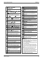
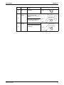
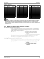
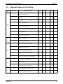
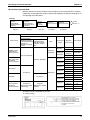
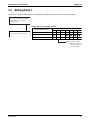
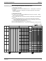
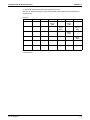
ED Reference
For items below, please refer to Engineering Data.
For except FTQ
No.
1
2
3
Item
Specification - Cooling Only
Specification - Heat Pump
Option List
ED No.
EDUS281120
EDUS281120
EDUS281120
Page
p. 7-13
p. 14-20
p. 100-102
Remarks
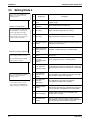
No.
1
2
Item
Specification - Heat Pump
Option List
ED No.
EDUS281008
EDUS281008
Page
Remarks
For FTQ
p. 4
p. 60
1. Safety Considerations ............................................................................. v
1.1 Safety Considerations for Repair ............................................................. v
1.2 Safety Considerations for Users ..............................................................vi
Part 1 General Information........................................................... 1
1. Model Names and Power Supply............................................................2
1.1 Cooling Only ............................................................................................ 2
1.2 Heat Pump ............................................................................................... 2
2. External Appearance ..............................................................................3
2.1 Indoor Units.............................................................................................. 3
2.2 Remote Controller .................................................................................... 4
2.3 Outdoor Units ........................................................................................... 4
Part 2 Refrigerant Circuit ............................................................. 5
1. Refrigerant Circuit ...................................................................................6
1.1 RZR18 / 24 / 30PVJU
RZQ18 / 24PVJU9
RZQ30PVJU ............................................................................................ 6
1.2 RZR36 / 42PVJU
RZQ36 / 42PVJU(9) ................................................................................. 8
Table of Contents
i
SiUS281117
2. Functional Parts Layout ........................................................................10
2.1 RZR18 / 24 / 30PVJU
RZQ18 / 24PVJU9
RZQ30PVJU .......................................................................................... 10
Part 3 Remote Controller ........................................................... 11
1. Wired Remote Controller ......................................................................12
1.1
1.2
1.3
1.4
Applicable Models .................................................................................. 12
Names and Functions ............................................................................ 13
MAIN/SUB Setting when Using 2 Remote Controllers........................... 17
Centralized Control Group No. Setting .................................................. 19
2. Wireless Remote Controller ..................................................................22
2.1 Applicable Models .................................................................................. 22
2.2 Names and Functions ............................................................................ 22
2.3 Address and MAIN/SUB Setting ............................................................ 24
3. Service Mode ........................................................................................25
3.1 BRC1D71 ............................................................................................... 25
3.2 BRC1E71 ............................................................................................... 28
4. Inspection Mode....................................................................................30
Part 4 Function and Control ....................................................... 31
1. Function General ..................................................................................32
1.1 Operation Mode ..................................................................................... 32
2. Basic Control.........................................................................................33
2.1
2.2
2.3
2.4
Normal Operation................................................................................... 33
Compressor PI Control .......................................................................... 34
Electronic Expansion Valve PI Control .................................................. 35
Cooling Operation Fan Control .............................................................. 36
3. Special Control......................................................................................37
3.1
3.2
3.3
3.4
3.5
3.6
3.7
Startup Control ....................................................................................... 37
Oil Return Operation .............................................................................. 38
Defrosting Operation .............................................................................. 40
Pump Down Residual Operation............................................................ 41
Restart Standby ..................................................................................... 42
Stopping Operation ................................................................................ 42
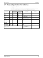
Pressure Equalization Prior to Startup ................................................... 43
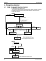
4. Protection Control .................................................................................44
4.1
4.2
4.3
4.4
High Pressure Protection Control .......................................................... 44
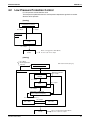
Low Pressure Protection Control ........................................................... 45
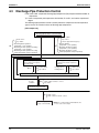
Discharge Pipe Protection Control ......................................................... 46
Inverter Protection Control ..................................................................... 47
5. Other Control ........................................................................................48
5.1 Heating Operation Prohibition ................................................................ 48
6. Outline of Control (Indoor Unit) .............................................................49
6.1 Drain Pump Control ............................................................................... 49
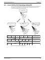
6.2 Louver Control for Preventing Ceiling Dirt ............................................. 51
ii
Table of Contents
SiUS281117
6.3
6.4
6.5
6.6
6.7
6.8
6.9
6.10
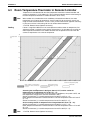
Room Temperature Thermistor in Remote Controller............................ 52
Thermostat Control with Operation Mode Set to "AUTO" ...................... 54
Freeze-up Prevention ............................................................................ 55
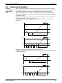
View of Operations of Swing Flaps ........................................................ 56
Hot Start Control (In Heating Operation Only) ....................................... 57
Heater Control (FTQ) ............................................................................. 59
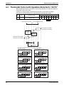
4 Step Thermostat Processing (FTQ) .................................................... 62
Interlocked with External Equipment (FTQ) ........................................... 63
Part 5 Field Setting..................................................................... 65
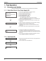
1. Test Operation ......................................................................................66
1.1 Procedure and Outline ........................................................................... 66
1.2 Operation when Power is Turned ON .................................................... 69
2. Field Setting from Remote Controller....................................................70
2.1 Wired Remote Controller ....................................................................... 70
2.2 Wireless Remote Controller ................................................................... 73
2.3 Setting Contents and Code No. for Indoor Units.................................... 74
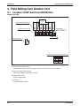
3. Field Setting from Outdoor Unit ............................................................80
3.1
3.2
3.3
3.4
3.5
3.6
3.7
Location of DIP Switch and BS Button................................................... 80
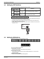
Setting by DIP Switches......................................................................... 81
Setting by BS Buttons ............................................................................ 81
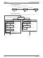
Setting Mode 1 ....................................................................................... 83
Setting Mode 2 ....................................................................................... 84
Monitor Mode ......................................................................................... 86
Detailed Explanation of Setting Modes .................................................. 87
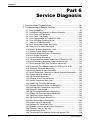
Part 6 Service Diagnosis ............................................................ 94
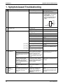
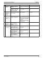
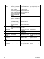
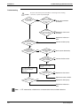
1. Symptom-based Troubleshooting .........................................................96
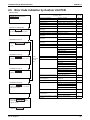
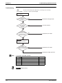
2. Troubleshooting by Remote Controller .................................................99
2.1
2.2
2.3
2.4
2.5
2.6
2.7
2.8
2.9
2.10
2.11
2.12
2.13
2.14
2.15
2.16
2.17
2.18
Table of Contents
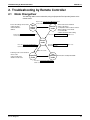
Mode ChangeOver................................................................................. 99
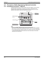
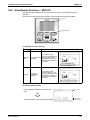
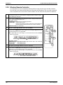
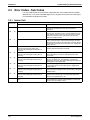
Procedure of Self-diagnosis by Remote Controller .............................. 100
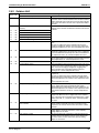
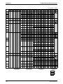
Error Codes and Description................................................................ 103
Error Codes - Sub Codes..................................................................... 104
Error Code Indication by Outdoor Unit PCB ........................................ 107
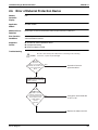
Error of External Protection Device...................................................... 109
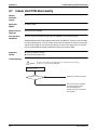
Indoor Unit PCB Abnormality ............................................................... 110
Drain Water Level System Abnormality ............................................... 111
Indoor Unit Fan Motor Abnormality ...................................................... 113
Swing Flap Motor Abnormality / Lock .................................................. 115
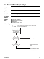
Abnormal Power Supply Voltage ......................................................... 117
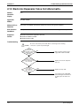
Electronic Expansion Valve Coil Abnormality ...................................... 118
Drain System Abnormality ................................................................... 120
Capacity Setting Abnormality ............................................................... 121
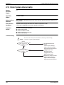
Transmission Error between Indoor Unit PCB and Fan PCB............... 122
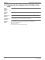
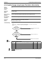
Heat Exchanger (Liquid pipe) Thermistor Abnormality ........................ 124
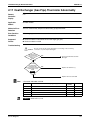
Heat Exchanger (Gas Pipe) Thermistor Abnormality ........................... 125
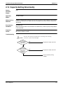
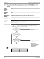
Combination Error between Indoor Unit PCB and Fan PCB................ 126
iii
SiUS281117
2.19
2.20
2.21
2.22
2.23
2.24
2.25
2.26
2.27
2.28
2.29
2.30
2.31
2.32
2.33
2.34
2.35
2.36
2.37
2.38
2.39
2.40
2.41
2.42
2.43
2.44
2.45
2.46
2.47
2.48
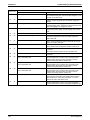
Suction Air Thermistor Abnormality ..................................................... 127
Humidity Sensor System Abnormality.................................................. 128
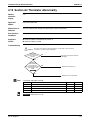
Room Temperature Thermistor in Remote Controller Abnormality...... 129
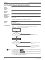
Outdoor Unit PCB Abnormality ............................................................ 130
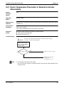
High Pressure Abnormality .................................................................. 131
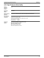
Actuation of Low Pressure Sensor....................................................... 133
Inverter Compressor Motor Lock ......................................................... 135
Outdoor Unit Fan Motor Abnormality ................................................... 137
Electronic Expansion Valve Coil Abnormality ...................................... 138
Discharge Pipe Temperature Control Error.......................................... 141
Refrigerant Overcharged ..................................................................... 143
High Pressure Switch System Abnormality.......................................... 144
Outdoor Unit Fan Motor Signal Abnormality ........................................ 145
Thermistor System Abnormality ........................................................... 146
High Pressure Sensor Abnormality ...................................................... 147
Low Pressure Sensor Abnormality....................................................... 149
Outdoor Unit PCB Abnormality ............................................................ 151
Radiation Fin Temperature Rise .......................................................... 153
Momentary Overcurrent of Inverter Compressor ................................. 154
Electronic Thermal (Time Lag)............................................................. 155
Inverter Startup Error ........................................................................... 157
Transmission Error (between Control and Inverter PCB)..................... 159
Radiation Fin Thermistor Abnormality.................................................. 160
Refrigerant Shortage............................................................................ 161
Power Supply Voltage Abnormality...................................................... 162
Check Operation not Executed ............................................................ 164
Transmission Error (between Indoor Units and Outdoor Units) ........... 165
Transmission Error (between Remote Controller and Indoor Unit) ...... 168
Transmission Error (between Main and Sub Remote Controllers)....... 169
Transmission Error
(between Centralized Remote Controller and Indoor Unit) .................. 170
2.49 System is not Set yet ........................................................................... 172
2.50 Check ................................................................................................... 173
Part 7 Appendix ........................................................................ 182
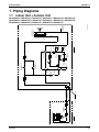
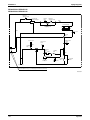
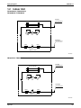
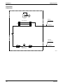
1. Piping Diagrams..................................................................................183
1.1 Indoor Unit + Outdoor Unit ................................................................... 183
1.2 Indoor Unit ........................................................................................... 185
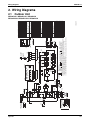
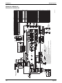
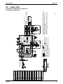
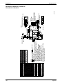
2. Wiring Diagrams .................................................................................187
2.1 Outdoor Unit......................................................................................... 187
2.2 Indoor Unit ........................................................................................... 189
iv
Table of Contents
Safety Considerations
SiUS281117
1. Safety Considerations
Read these SAFETY CONSIDERATIONS carefully before
performing any repair work. Comply with these safety
symbols without fail.Meanings of DANGER, WARNING,
CAUTION, and NOTE Symbols:
DANGER .............. Indicates an imminently hazardous
situation which, if not avoided, will
result in death or serious injury.
WARNING ............ Indicates a potentially hazardous
situation which, if not avoided, could
result in death or serious injury.
CAUTION .............. Indicates a potentially hazardous
situation which, if not avoided, may
result in minor or moderate injury. It
may also be used to alert against
unsafe practices.
NOTE .................. Indicates situations that may result
in equipment or property-damage
accidents only.
1.1
Safety Considerations for Repair
• If refrigerant gas leaks during repair or service,
ventilate the area immediately. Refrigerant gas may
produce toxic gas if it comes into contact with flames.
Refrigerant gas is heavier than air and replaces
oxygen. In the event of an accident, a massive leak
could lead to oxygen depletion, especially in
basements, and an asphyxiation hazard could occur
leading to serious injury or death.
• Do not start or stop the air conditioner operation by
plugging or unplugging the power cable plug if a
plug is used. Plugging or unplugging the power
cable plug to operate the equipment may cause an
electrical shock or fire.
• Use parts listed in the service parts list and
appropriate tools to conduct repair work. The use of
inappropriate parts or tools may cause an electrical
shock or fire.
• Disconnect power before disassembling the
equipment for repairs. Working on the equipment
that is connected to the power supply may cause an
electric shock. If it is necessary to supply power to
the equipment to conduct repairs or to inspect the
circuits, do not touch any electrically charged
sections of the equipment.
• The step-up capacitor supplies high-voltage
electricity to the electrical components of the
outdoor unit. Discharge the capacitor completely
before conducting repair work. A charged capacitor
may cause an electrical shock.
• If refrigerant gas is discharged during repair work,
do not touch the discharged refrigerant gas. The
refrigerant gas may cause frostbite.
Never use tools or materials designed for R22
refrigerant systems on an R410A refrigerant system.
Doing so can cause a serious accident or an
equipment failure.
• Check to see if the parts and wires are mounted and
connected properly, and if the connections at the
soldered or crimped terminals are secure. Improper
installation and connections may cause excessive
heat generation, fire, or electrical shock.
• Prior to disconnecting the suction or discharge pipe
from the compressor at the welded section,
pump-down the refrigerant gas completely in a wellventilated place first. If there is refrigerant gas or oil
remaining inside the compressor, the refrigerant gas
or oil can discharge when the pipe is being
disconnected and it may cause an injury.
• Wear a safety helmet, gloves, and a safety belt when
working at an elevated height of more than 6.5 ft (2 m).
Insufficient safety measures may cause a fall resulting
in injury.
• Do not mix air or gas other than the specified
refrigerant R410A to the refrigerant system. If air
enters the refrigerant systems, it can cause an
excessive high pressure resulting in equipment
damage and injury.
• When relocating the equipment, check if the new
installation site has sufficient strength to withstand
the weight of the equipment. If the installation site
does not have sufficient strength and the equipment
is not properly secured, the equipment may fall and
cause injury.
• Securely fasten the outside unit terminal cover
(panel). If the terminal cover/panel is not fastened
properly, dust or water may enter the outside unit
causing fire or electric shock.
• When relocating the system, keep the refrigerant
circuit free from substances other than the specified
refrigerant (R-410A) such as air. Any presence of air
or other foreign substance in the refrigerant circuit
can cause an abnormal pressure rise or rupture,
resulting in injury.
• If refrigerant gas leaks, locate the leaking point and
repair it before charging refrigerant. After charging
refrigerant, check for refrigerant leaks. If the leaking
point cannot be located and the repair work must be
stopped, perform a pump-down and close the
service valve to prevent the refrigerant gas from
leaking into the room. The refrigerant gas itself is
harmless, but it may generate toxic gases if it comes
into contact with flames.
• Do not repair the electrical components with wet
hands. Working on the equipment with wet hands
may cause an electrical shock.
• Use only pipes, flare nuts, tools, and other materials
designed specifically for R410A refrigerant systems.
v
SiUS281117
Safety Considerations
• Do not clean the air conditioner by splashing water
on it. Washing the unit with water may cause an
electrical shock.
• Check the grounding and repair it if the equipment is
not properly grounded. Improper grounding may
cause an electrical shock.
• Ground the unit when repairing equipment in a
humid or wet place to avoid electrical shocks.
• Measure the insulation resistance after the repair.
• Turn off the power when cleaning the equipment to
prevent internal fans that rotate at high speed from
starting suddenly as they can cause injury.
• Let the refrigerant lines cool down before
performing any repair work. Working on the unit
when the refrigerant lines are hot may cause burns.
• All welding and cutting operations must be done in a
well-ventilated place to prevent the accumulation of
toxic fumes or possibly oxygen deficiency to occur.
1.2
The resistance must be 1M or higher. Faulty
insulation may cause an electrical shock.
• Check the drainage of the indoor unit after finishing
repair work. Faulty drainage may cause water to
enter the room resulting in wet floors and furniture.
• Do not tilt the unit when removing it. The water
inside the unit may spill resulting in wet floors and
furniture.
• Dismantling of the unit, disposal of the refrigerant,
oil, and additional parts, should be done in
accordance with the relevant local, state, and
national regulations.
Safety Considerations for Users
• Never attempt to modify the equipment. Doing so can
cause electrical shock, excessive heat generation, or
fire.
• Never remove the fan guard of the unit. A fan
rotating at high speed without the fan guard is very
dangerous.
• If the power cable and lead wires have scratches or
have become deteriorated, have them replaced.
Damaged cable and wires may cause an electrical
shock or fire.
• Before cleaning the unit, stop the operation of the
unit by turning the power off or by pulling the power
cable plug out from its receptacle. Otherwise an
electrical shock or injury may result.
• Do not use a joined power cable or an extension
cord, or share the same power outlet with other
electrical appliances as it may cause an electrical
shock or fire.
• Do not wipe the controller operation panel with
benzene, thinner, chemical dust cloth, etc. The panel
may get discolored or the coating can peel off. If it is
extremely dirty, soak a cloth in a water-diluted
neutral detergent, squeeze it well, and wipe the panel
clean. Then wipe it with another dry cloth.
• Use an exclusive power circuit for the equipment.
Insufficient circuit amperage capacity may cause an
electrical shock or fire.
• Do not damage or modify the power cable. Damaged
or modified power cables may cause an electrical
shock or fire. Placing heavy items on the power
cable or pulling the power cable may damage the
cable.
• Check the unit foundation for damage on a continual
basis, especially if it has been in use for a long time.
If left in a damaged condition, the unit may fall and
cause injury. If the installation platform or frame has
corroded, have it replaced. A corroded platform or
frame may cause the unit to fall resulting in injury.
• If the unit has a power cable plug and it is dirty, clean
the plug before securely inserting it into a power
outlet. If the plug has a loose connection, tighten it
or it may cause electrical shock or fire.
• After replacing the battery in the remote controller,
dispose of the old battery to prevent children from
swallowing it. If a child swallows the battery, see a
doctor immediately.
vi
SiUS281117
Part 1
General Information
1. Model Names and Power Supply............................................................2
1.1 Cooling Only ............................................................................................ 2
1.2 Heat Pump ............................................................................................... 2
2. External Appearance ..............................................................................3
2.1 Indoor Units.............................................................................................. 3
2.2 Remote Controller .................................................................................... 4
2.3 Outdoor Units ........................................................................................... 4
General Information
1
SiUS281117
Part 2
Refrigerant Circuit
1. Refrigerant Circuit ...................................................................................6
1.1 RZR18 / 24 / 30PVJU
RZQ18 / 24PVJU9
RZQ30PVJU ............................................................................................ 6
1.2 RZR36 / 42PVJU
RZQ36 / 42PVJU(9) ................................................................................. 8
2. Functional Parts Layout ........................................................................10
2.1 RZR18 / 24 / 30PVJU
RZQ18 / 24PVJU9
RZQ30PVJU .......................................................................................... 10
Refrigerant Circuit
5
SiUS281117
Model Names and Power Supply
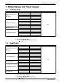
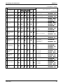
1. Model Names and Power Supply
1.1
Cooling Only
Indoor unit
FCQ18PAVJU
FCQ24PAVJU
Ceiling mounted cassette
type
FCQ30PAVJU
(Round flow)
FCQ36PAVJU
FCQ42PAVJU
FHQ18PVJU
FHQ24PVJU
Ceiling suspended type
FHQ30PVJU
FHQ36MVJU
FHQ42MVJU
FAQ18PVJU
Wall mounted type
FAQ24PVJU
FBQ18PVJU
FBQ24PVJU
Ceiling mounted duct type
FBQ30PVJU
FBQ36PVJU
FBQ42PVJU
Note:
1.2
Power supply, Compatibility symbol
VJU
1. : New model or changed model
2. Power supply intake: outdoor unit
3. VJ: 1 phase, 208/230V, 60Hz
U (VJU, TJU): Standard Compatibility Symbol
Heat Pump
Indoor unit
FCQ18PAVJU
FCQ24PAVJU
Ceiling mounted cassette
type
FCQ30PAVJU
(Round flow)
FCQ36PAVJU
FCQ42PAVJU
FHQ18PVJU
FHQ24PVJU
Ceiling suspended type
FHQ30PVJU
FHQ36MVJU
FHQ42MVJU
FAQ18PVJU
Wall mounted type
FAQ24PVJU
FBQ18PVJU
FBQ24PVJU
Ceiling mounted duct type
FBQ30PVJU
FBQ36PVJU
FBQ42PVJU
Air handling unit
Note:
2
Outdoor unit
RZR18PVJU
RZR24PVJU
RZR30PVJU
RZR36PVJU
RZR42PVJU
RZR18PVJU
RZR24PVJU
RZR30PVJU
RZR36PVJU
RZR42PVJU
RZR18PVJU
RZR24PVJU
RZR18PVJU
RZR24PVJU
RZR30PVJU
RZR36PVJU
RZR42PVJU
Outdoor unit
RZQ18PVJU9
RZQ24PVJU9
RZQ30PVJU
RZQ36PVJU9
RZQ42PVJU9
RZQ18PVJU9
RZQ24PVJU9
RZQ30PVJU
RZQ36PVJU9
RZQ42PVJU9
RZQ18PVJU9
RZQ24PVJU9
RZQ18PVJU9
RZQ24PVJU9
RZQ30PVJU
RZQ36PVJU9
RZQ42PVJU9
FTQ18PAVJU
RZQ18PVJU
FTQ24PAVJU
RZQ24PVJU
Power supply, Compatibility symbol
VJU
1. : New model or changed model
2. Power supply intake: outdoor unit
3. VJ: 1 phase, 208/230V, 60Hz
U (VJU, TJU): Standard Compatibility Symbol
General Information
External Appearance
SiUS281117
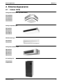
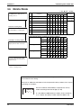
2. External Appearance
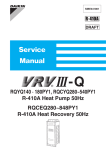
2.1
Indoor Units
Ceiling Mounted Cassette Type (Round Flow)
FCQ18PAVJU
FCQ24PAVJU
FCQ30PAVJU
FCQ36PAVJU
FCQ42PAVJU
Ceiling Suspended Type
FHQ18PVJU
FHQ24PVJU
FHQ30PVJU
FHQ36MVJU
FHQ42MVJU
Wall Mounted Type
FAQ18PVJU
FAQ24PVJU
Ceiling Mounted Duct Type
FBQ18PVJU
FBQ24PVJU
FBQ30PVJU
FBQ36PVJU
FBQ42PVJU
Air Handling Unit
FTQ18PAVJU
FTQ24PAVJU
General Information
3
SiUS281117
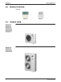
2.2
External Appearance
Remote Controller
Wired Type
77 F
69 F
77
F
BRC1D71
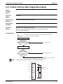
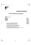
2.3
BRC1E71
Outdoor Units
RZR18PVJU
RZR24PVJU
RZR30PVJU
RZQ18PVJU9
RZQ24PVJU9
RZQ30PVJU
RZR36PVJU
RZR42PVJU
RZQ36PVJU9
RZQ42PVJU9
4
General Information
SiUS281117
Refrigerant Circuit
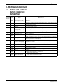
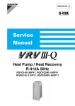
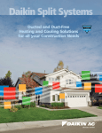
1. Refrigerant Circuit
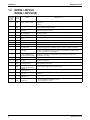
1.1
RZR18 / 24 / 30PVJU
RZQ18 / 24PVJU9
RZQ30PVJU
No. in
refrigerant Electric
system
Symbol
diagram
Major Function
A
M1C
Inverter compressor (INV.)
Inverter compressor is operated on frequencies between 52 Hz and 177 Hz by using
the inverter.
17 steps
D
M1F
Inverter fan
Because the system is an air heat exchange type, the fan is operated at 8-step rotation
speed by using the inverter.
E
Y1E
Electronic expansion valve
(Main: EV1)
While in heating operation, PI control is applied to keep the outlet superheated degree
of air heat exchanger constant.
G
Y2S
Solenoid valve (Hot gas: SVP) Prevents the low pressure from transient falling.
Y3S
Solenoid valve (Receiver gas
discharging: SVG)
Collects refrigerant to receiver.
Y1S
Four-way valve
Switches the operation mode between cooling and heating.
J
M
6
Name
N
S1NPH High pressure sensor
O
S1NPL Low pressure sensor
Detects high pressure.
Detects low pressure.
High pressure switch (For
INV. compressor)
In order to prevent the increase of high pressure when an error occurs, this switch is
activated at high pressure of 580 psi or more to stop the compressor operation.
P
S1PH
S
—
Fusible plug
In order to prevent the increase of pressure when abnormal heating is caused by fire
or others, the fusible part of the plug is molten at a temperature of 158 to 167°F to
release the pressure into the atmosphere.
T
—
Pressure regulating valve 1
(Receiver to discharge pipe)
This valve opens at a pressure of 580 psi for prevention of pressure increase, thus
resulting in no damage of functional parts due to the increase of pressure in
transportation or storage.
1
R1T
Thermistor (Outdoor air: Ta)
Detects outdoor air temperature, correct discharge pipe temperature, and others.
2
R2T
Thermistor (Discharge pipe:
Tdi)
Detects discharge pipe temperature, make the temperature protection control of
compressor, and others.
3
R3T
Thermistor (Suction pipe 1:
Ts1)
Detects suction pipe temperature, keep the suction superheated degree constant in
heating operation, and others.
4
R4T
Thermistor (Heat exchanger
deicer: Tb)
Detects liquid pipe temperature of air heat exchanger, determine defrosting operation,
and others.
5
R5T
Thermistor (Suction pipe 2:
Ts2)
Calculates internal temperature of compressor.
10
R10T
Thermistor (Radiation fin)
•
•
•
Outdoor unit fan speed control.
Inverter radiation fin temperature control.
Pressure difference control.
Refrigerant Circuit
Refrigerant Circuit
Indoor unit
Fan
Filter
Electronic
Indoor heat exchanger
Field piping f 5/8
Stop valve
(with service port 5/16" flare)
Filter
Field piping f 3/8
Filter
R3T
G
R5T
5
A
Solenoid
valve
SV
Compressor
accumulator
Accumulator
Capillary tube
3
Solenoid
valve
J
S
Pressure
regulating valve
Electronic
Fusible plug
T
E
1
N
P
High
pressure
switch
S1PH
High
pressure
sensor
S1NPH
Check valve
Muffler
M
4
R4T
* R10T
Fan
Service port
(5/16" flare)
M
D
Outdoor unit
heat exchanger
C: 3D062238C
* This thermistor is near the electrical components box.
Outdoor unit
2
R2T
O
Compressor
Low
pressure
sensor
S1NPL
Filter
Four way valve
Filter
R1T
Refrigerant Circuit
SiUS281117
7
SV
SiUS281117
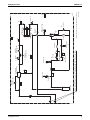
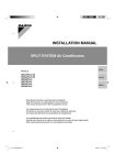
1.2
Refrigerant Circuit
RZR36 / 42PVJU
RZQ36 / 42PVJU(9)
No. in
refrigerant Electric
system
Symbol
diagram
Major Function
A
M1C
Inverter compressor (INV.)
Inverter compressor is operated on frequencies between 36 Hz and 195 Hz by using
the inverter.
31 steps
D
M1F
M2F
Inverter fan
Because the system is of an air heat exchange type, the fan is operated at 8-step
rotation speed by using the inverter.
E
Y1E
Electronic expansion valve
(Main: EV1)
While in heating operation, PI control is applied to keep the outlet superheated degree
of air heat exchanger constant.
F
Y3E
Electronic expansion valve
(Subcooling: EV3)
Pl control is applied to keep the outlet superheated degree of subcooling heat
exchanger constant.
G
Y2S
Solenoid valve (Hot gas: SVP) Prevents the low pressure from transient falling.
H
Y3S
Solenoid valve (Unload circuit:
Unloading operation of compressor.
SVUL)
Y1S
Four-way valve
M
8
Name
N
S1NPH High pressure sensor
O
S1NPL Low pressure sensor
es the operation mode between cooling and heating.
Detects high pressure.
Detects low pressure.
High pressure switch (For
INV. compressor)
In order to prevent the increase of high pressure when an error occurs, this switch is
activated at high pressure of 580 PSI or more to stop the compressor operation.
P
S1PH
S
—
Fusible plug
In order to prevent the increase of pressure when abnormal heating is caused by fire
or others, the fusible part of the plug is molten at a temperature of 158 to 167°F to
release the pressure into the atmosphere.
T
—
Pressure regulating valve 1
(Receiver to discharge pipe)
This valve opens at a pressure of 580 PSI for prevention of pressure increase, thus
resulting in no damage of functional parts due to the increase of pressure in
transportation or storage.
1
R1T
Thermistor (Outdoor air: Ta)
Detects outdoor air temperature, correct discharge pipe temperature, and others.
2
R2T
Thermistor (INV. discharge
pipe: Tdi)
Detects discharge pipe temperature, make the temperature protection control of
compressor, and others.
3
R3T
Thermistor
(Suction pipe1: Ts1)
Detects suction pipe temperature, keep the suction superheated degree constant in
heating operation, and others.
4
R4T
Thermistor (Subcooling heat
exchanger gas pipe: Tsh)
Controls of subcooling electronic expansion valve.
5
R5T
Thermistor
(Suction pipe2: Ts2)
Calculates internal temperature of compressor.
6
R6T
Thermistor (Heat exchanger
deicer: Tb)
Detects liquid pipe temperature of air heat exchanger, determine defrosting operation,
and others.
7
R7T
Thermistor
(Liquid pipe: Tl)
Detects refrigerant overcharge in check operation, and others.
8
FIN
TH
Thermistor
(Radiation fin)
•
•
•
Outdoor unit fan speed control.
Inverter radiation fin temperature control.
Pressure difference control.
Refrigerant Circuit
Capillary
5
R5T
Service port
R4T
4
T
R3T
O
A
Compressor
R2T
Filter
Solenoid
H
3
2
Pressure
regulating valve
Fusible
plug
Low pressure
S
Capillary
P
High pressure
E
Electronic
expansion valve
Stop valve (With service port on field piping side 5/16'' flare connection)
Accumulator
7
R7T
F
S1NPL
Double pipe
heat exchanger
S1PH
Refrigerant Circuit
D
Filter
G
Solenoid
N
Fan
High pressure
sensor
S1NPH
M
Four way
valve
D
Outdoor unit
Heat exchanger
6
Service port
R6T
8
*
FIN TH
3D065366A
* This thermistor is near the electrical components box.
Capillary
Fan
Filter
1
R1T
Oil
separator
Electronic
expansion valve
Refrigerant Circuit
SiUS281117
9
SiUS281117
Functional Parts Layout
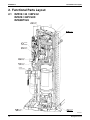
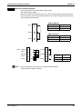
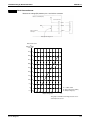
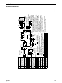
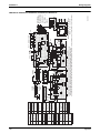
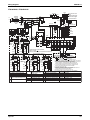
2. Functional Parts Layout
2.1
RZR18 / 24 / 30PVJU
RZQ18 / 24PVJU9
RZQ30PVJU
Y1S LEAD WIRE
(HIGH VOLTAGE)
R1T LEAD WIRE
(LOW VOLTAGE)
Y2S LEAD WIRE
(HIGH VOLTAGE)
R2T LEAD WIRE
(LOW VOLTAGE)
Y3S LEAD WIRE
(HIGH VOLTAGE)
R3T LEAD WIRE
(LOW VOLTAGE)
THERMAL
INSULATION TUBE
Y1E LEAD WIRE
(LOW VOLTAGE)
R4T LEAD WIRE
(LOW VOLTAGE)
1P241839F
10
Refrigerant Circuit
SiUS281117
Part 3
Remote Controller
1. Wired Remote Controller ......................................................................12
1.1
1.2
1.3
1.4
Applicable Models .................................................................................. 12
Names and Functions ............................................................................ 13
MAIN/SUB Setting when Using 2 Remote Controllers........................... 17
Centralized Control Group No. Setting .................................................. 19
2. Wireless Remote Controller ..................................................................22
2.1 Applicable Models .................................................................................. 22
2.2 Names and Functions ............................................................................ 22
2.3 Address and MAIN/SUB Setting ............................................................ 24
3. Service Mode ........................................................................................25
3.1 BRC1D71 ............................................................................................... 25
3.2 BRC1E71 ............................................................................................... 28
4. Inspection Mode....................................................................................30
Remote Controller
11
SiUS281117
Wired Remote Controller
1. Wired Remote Controller
1.1
Applicable Models
Model Series
Wired Remote Controller with Weekly
Schedule Timer
Navigation Remote Controller
12
FCQ-PA
FHQ-P
FAQ-P
BRC1D71
FBQ-P
FTQ—
BRC1E71
Remote Controller
Wired Remote Controller
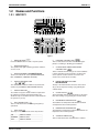
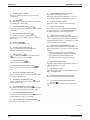
1.2
SiUS281117
Names and Functions
1.2.1 BRC1D71
6
3
23 7
8
9
2
1
10
4
11
12
14
22
17
25
16
13
15 18
19
20
21
29
5
24
33
26
35
27
36
37
28
30
31
34
32
Figure 1
1
ON/OFF BUTTON
Press the ON/OFF button to start or stop the system.
2
OPERATION LAMP
The operation lamp lights up during operation or blinks if
an error occurs.
8
EXTERNAL CONTROL ICON
This icon indicates that another controller with higher
priority is controlling or disabling your installation.
3
OPERATION MODE ICON
These icons indicate the current operation mode (FAN,
DRY, AUTOMATIC, COOLING, HEATING).
CHANGE-OVER UNDER CENTRALIZED
CONTROL ICON
This icon indicates that the change-over of the installation
is under centralized control assigned to another indoor
unit or optional cool/heat selector connected to the
outdoor unit (= main remote controller).
4
10
VENTILATION MODE ICON
9
DAY OF THE WEEK INDICATOR
MON TUE WED THU FRI SAT SUN
These icons indicate the current ventilation mode (Heat Reclaim
Ventilator only) (AUTOMATIC, HEAT EXCHANGE, BYPASS).
5
VENTILATION ICON
The ventilation icon appears when the ventilation is adjusted with
the ventilation amount button (Heat Reclaim Ventilator only).
Simultaneously, the ventilation amount is indicated by the
fan speed icon (see 22).
6
AIR CLEANING ICON
This icon indicates that the air cleaning unit (option) is
operational.
7
AWAY ICON
The away icon shows the status of the away function.
ON
AWAY is enabled
BLINKING
AWAY is active
OFF
AWAY is disabled
Remote Controller
The day of the week indicator shows the current week
day (or the set day when reading or programming the
schedule timer).
11 CLOCK DISPLAY
The clock display indicates the current time (or the action
time when reading or programming the schedule timer).
12 MAXIMUM SET TEMPERATURE
The maximum set temperature indicates the maximum
set temperature when in limit operation.
13 MINIMUM SET TEMPERATURE
The minimum set temperature indicates the minimum set
temperature when in limit operation.
14 SCHEDULE TIMER ICON
This icon indicates that the schedule timer is enabled.
13
SiUS281117
15 ACTION ICONS 1 2 3 4 5
These icons indicate the actions for each day of the
schedule timer.
16 OFF ICON
This icon indicates that the OFF action is selected when
programming the schedule timer.
17 INSPECTION REQUIRED
and
These icons indicate that inspection is required. Consult
your installer.
18 SET TEMPERATURE DISPLAY
This indicates the current set temperature of the
installation (not shown in LIMIT operation or in FAN or
DRY mode).
19 SETTING
Not used, for service purposes only.
20 AIRFLOW DIRECTION ICON
This icon indicates the airflow direction (only for
installations with motorized airflow flaps).
21
NOT AVAILABLE
is displayed whenever a non-installed option is
addressed or a function is not available.
22 FAN SPEED ICON
This icon indicates the set fan speed.
23 DEFROST/HOTSTART MODE ICON
This icon indicates that the defrost/hotstart mode is
active.
24 AIR FILTER CLEANING TIME ICON
This icon indicates the air filter must be cleaned. Refer to
the manual of the indoor unit.
25 ELEMENT CLEANING TIME ICON
This icon indicates the element must be cleaned (Heat
Reclaim Ventilator only).
26 VENTILATION MODE BUTTON
The ventilation mode button operates the Heat Reclaim Ventilator;
refer to the Heat Reclaim Ventilator manual for more details.
Wired Remote Controller
29 PROGRAMMING BUTTON FUNCTION
This button is a multi-purpose button.
Depending on the previous manipulations of the user,
the programming button can have various functions.
30 SCHEDULE TIMER BUTTON
This button enables or disables the schedule timer.
31 TIME ADJUST BUTTON
These buttons are used to adjust the clock or, when in
programming mode, to adjust the programmed action
time. Both buttons have an auto-repeat function.
32 TEMPERATURE ADJUST BUTTONS
These buttons are used to adjust the current setpoint or,
when in programming mode, to adjust the programmed
setpoint temperature (step = 1°F). Both buttons are also
used to adjust the day of the week.
33 OPERATION CHANGE/MIN-MAX BUTTON
This button is a multi-purpose button. Depending on the
previous manipulations of the user, it can have following
functions:
1 select the operation mode of the installation
(FAN, DRY, AUTOMATIC, COOLING, HEATING)
2 toggle between minimum temperature and
maximum temperature when in limit operation
34 SETPOINT/LIMIT BUTTON
This button toggles between setpoint, limit operation or
(programming mode only).
35 FAN SPEED BUTTON
This button toggles between L (Low), H (High), HH (very
High), AUTO (Automatic).
36 AIRFLOW DIRECTION ADJUST BUTTON
This button enables to adjust the airflow direction.
37
AIR FILTER CLEANING TIME ICON RESET
BUTTON
This button is used to reset the air filter cleaning time
icon.
27 VENTILATION AMOUNT BUTTON
This button sets the ventilation amount; refer to the Heat
Reclaim Ventilator manual for more details.
28 INSPECTION/TEST OPERATION BUTTON
Not used, for service purposes only.
3P166742-1
14
Remote Controller
Wired Remote Controller
SiUS281117
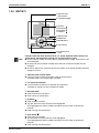
1.2.2 BRC1E71
1. Operation mode
selector button
11. LCD (with backlight)
4. Up button
5. Down button
6. Right button
7. Left button
9. Operation lamp
8. On/Off button
3. Menu/OK button
10. Cancel button
2. Fan speed control
button
Note:
Functions other than basic operation items (i.e., On/Off, Operation mode selector, Fan
speed control, and temperature settings) are set from the menu screen.
Do not install the remote controller in places exposed to direct sunlight, otherwise the LCD
will be damaged.
Do not pull or twist the remote controller cord, otherwise the remote controller may be
damaged.
Do not use objects with sharp ends to press the buttons on the remote controller otherwise
damage may result.
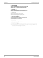
1. Operation mode selector button
Press this button to select the operation mode of your preference.
Available modes vary with the indoor unit model.
2. Fan speed control button
Press this button to select the fan speed of your preference.
Available fan speeds vary with the indoor unit model.
3. Menu/OK button
Used to indicate the main menu.
Used to enter the selected item.
4. Up button
Used to raise the setpoint.
The item above the current selection will be highlighted.
(The highlighted items will be scrolled continuously when the button is continuously
pressed.)
Used to change the selected item.
5. Down button
Used to lower the setpoint.
The item below the current selection will be highlighted.
(The highlighted items will be scrolled continuously when the button is continuously
pressed.)
Used to change the selected item.
Remote Controller
15
SiUS281117
Wired Remote Controller
6. Right button
Used to highlight the next items on the right-hand side.
Each screen is scrolled in the right-hand direction.
7. Left button
Used to highlight the next items on the left-hand side.
Each screen is scrolled in the left-hand direction.
8. On/Off button
Press this button and system will start.
Press this button again to stop the system.
9. Operation lamp (Green)
This lamp illuminates solid during normal operation.
This lamp blinks if an error occurs.
10. Cancel button
Used to return to the previous screen.
11. LCD (with backlight)
The backlight will be illuminated for approximately 30 seconds by pressing any button.
If 2 remote controllers are used to control a single indoor unit, only the controller to be
accessed first will have backlight functionality.
16
Remote Controller
Wired Remote Controller
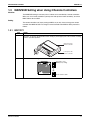
1.3
SiUS281117
MAIN/SUB Setting when Using 2 Remote Controllers
Situation
The MAIN/SUB setting is necessary when 1 indoor unit is controlled by 2 remote controllers.
When you use 2 remote controllers (control panel and separate remote controller), set one to
MAIN and the other to SUB.
Setting
The remote controllers are factory setting to MAIN, so you only have to change one remote
controller from MAIN to SUB. To change a remote controller from MAIN to SUB, proceed as
follows:
1.3.1 BRC1D71
Step
1
Action
Insert a flat-head screwdriver into the recess between the upper and lower part of the remote
controller, as shown in the illustration below. Gently pry off the upper part of the controller, working
from the 2 possible positions.
Upper part of the
remote controller
Lower part of the
remote controller
2
Turn the MAIN/SUB changeover switch on the PCB to “S”.
M
S
M
S
Remote Controller
The switch is set to
MAIN (factory setting)
Set the switch to SUB.
17
SiUS281117
Wired Remote Controller
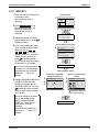
1.3.2 BRC1E71
The designation of the main and sub remote controllers can be swapped. Note that this change
requires turning the power OFF and then ON again.
Basic screen
is displayed.
Press and
hold Cancel
button for 4
seconds or
more.
Select "Switch Main Sub Controller"
and press Menu/OK button.
Service
Select "Main RC"
or "Sub RC" using
the / (Up/Down)
buttons, and then
press Menu/OK
button.
Press
Cancel
button
once.
settings menu
is displayed.
18
Press Cancel button.
Item 2 is
displayed.
Press Menu/OK
button.
Item 2 is
displayed.
Remote Controller
Wired Remote Controller
1.4
SiUS281117
Centralized Control Group No. Setting
1.4.1 BRC1D71
In order to conduct the centralized remote control using the centralized remote controller and
the unified ON/OFF controller, Group No. settings should be made by group using the operating
remote controller.
Make Group No. settings for centralized remote control using the operating remote controller.
1. While in normal mode, press and hold the “
” switch for a period of 4 seconds or more
to set the system to "Field Setting Mode".
2. Select the MODE No. “00” with the “
” button.
3. Use the “
” button to select the group No. for each group.
(Group numbers increase in the order of 1-00, 1-01, ... 1-15, 2-00, ... 4-15.)
4. Press “
” or “
” to set the selected group No.
5. Press “
” to return to the NORMAL MODE.
TEST
TEST
BRC1D71
Mode No.
Group No.
Field setting
mode
4
3
2
1,5
Note:
For setting group No. of Heat Reclaim Ventilator and wiring adaptor for other air
conditioners, etc., refer to the instruction manual attached.
NOTICE
Enter the group No. and installation place of the indoor unit into the attached installation table.
Be sure to keep the installation table with the operation manual for maintenance.
Remote Controller
19
SiUS281117
Wired Remote Controller
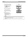
1.4.2 BRC1E71
In order to conduct the centralized remote control using the centralized remote controller and
the unified ON/OFF controller, Group No. settings should be made by group using the operating
remote controller.
Make Group No. settings for centralized remote control using the operating remote controller.
<Group Address (Unit)>
Basic screen
is displayed.
Press
Cancel
button
once.
Press and hold
Cancel button
for 4 seconds
or more.
Select "Group Address"
and then press Menu/OK
button.
Service
settings menu
is displayed.
Press Cancel
button once.
Item 2 is
displayed.
Press Cancel
button once.
Select "Group
Address (Unit)"
and then press
Menu/OK button.
Item 2 is
displayed.
Select the
desired Group
Address using
the /
(Up/Down)
buttons, and then
press Menu/OK
button.
Press Cancel
button once.
Service settings menu
Group Address
Note:
Item 2
Group Address (Group)
Group Address (Unit)
Select Group
Address using
the / buttons,
and then press
Menu/OK button.
Item 2 is
displayed.
Description
This menu is used to make group address setting for centralized
control.
It is also used to make group address setting by indoor unit.
For setting group No. of Heat Reclaim Ventilator and wiring adaptor for other air
conditioners, etc., refer to the installation manual attached.
NOTICE
Enter the group No. and installation place of the indoor unit into the attached installation table.
Be sure to keep the installation table with the operation manual for maintenance.
20
Remote Controller
Wired Remote Controller
SiUS281117
<Group Address (Group)>
Basic screen
is displayed.
Press
Cancel
button
once.
Press and hold
Cancel button
for 4 seconds
or more.
Select "Group Address"
and then press Menu/OK
button.
Service
settings menu
is displayed.
Press Cancel
button once.
Item 2 is
displayed.
Select "Group
Address (Group)"
and then press
Menu/OK button.
Press Cancel
button once.
Item 2 is
displayed.
Select the desired
Group Address
using the /
(Up/Down)
buttons, and then
press Menu/OK
button.
Press Cancel
button once.
Remote Controller
Press Menu/OK
button.
Item 2 is
displayed.
21
SiUS281117
Wireless Remote Controller
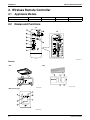
2. Wireless Remote Controller
2.1
Applicable Models
Model Series
Remote controller
2.2
FCQ-PA
—
FHQ-P
BRC7E83
FAQ-P
BRC7EA818
FBQ-P
BRC4C82
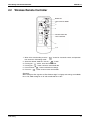
Names and Functions
1-1
1
8
1-2
3
10
6
11
4
9
2
13
5
12
15
7
14
16
17
3P107422-11J
Receiver
FHQ
FAQ
18
20
21
22 23
19
19
21 20
23
18
3P107422-8S
22
3P107422-17M
FBQ (separate type)
18
20
22
19
21
23
3P107422-21S
22
Remote Controller
Wireless Remote Controller
1
SiUS281117
14 AIRFLOW DIRECTION ADJUST BUTTON
DISPLAY “ ” (SIGNAL
TRANSMISSION)
OPERATION MODE SELECTOR BUTTON
15 Press this button to select OPERATION
MODE.
This lights up when a signal is being
transmitted.
DISPLAY “
“
”“
”“
”“
” (OPERATION MODE)
2 This display shows the current
OPERATION MODE. For Cooling Only
type, “
” (Auto) and “
” (Heating) are
not installed.
3
DISPLAY “
H
M
L
” (SET TEMPERATURE)
C
This display shows the set temperature.
hr.
DISPLAY “ hr.
”
(PROGRAMMED
TIME)
4
This display shows PROGRAMMED TIME
of the system start or stop.
5 DISPLAY “
6
DISPLAY “
” (AIRFLOW FLAP)
”“
FILTER SIGN RESET BUTTON
”
” (FAN SPEED)
The display shows the set fan speed.
16 Refer to the section of MAINTENANCE in
the operation manual attached to the
indoor unit.
INSPECTION/TEST OPERATION BUTTON
17 This button is used only by qualified service
persons for maintenance purposes.
EMERGENCY OPERATION SWITCH
18 This switch is readily used if the remote
controller does not work.
RECEIVER
19 This receives the signals from the remote
controller.
OPERATING INDICATOR LAMP (Red)
20 This lamp stays lit while the air
conditioner runs. It blinks when the unit is
in trouble.
TIMER INDICATOR LAMP (Green)
21
This lamp stays lit while the timer is set.
DISPLAY “
TEST ”
(INSPECTION/ TEST OPERATION)
7 When the INSPECTION/TEST
OPERATION BUTTON is pressed, the
display shows the system mode is in.
ON/OFF BUTTON
8 Press the button and the system will start.
Press the button again and the system will
stop.
FAN SPEED CONTROL BUTTON
9 Press this button to select the fan speed,
HIGH or LOW, of your choice.
TEMPERATURE SETTING BUTTON
10 Use this button for SETTING
TEMPERATURE (Operates with the front
cover of the remote controller closed.)
PROGRAMMING TIMER BUTTON
Use this button for programming “START
11 and/or STOP” time. (Operates with the
front cover of the remote controller
opened.)
12 TIMER MODE START/STOP BUTTON
13 TIMER RESERVE/CANCEL BUTTON
22
AIR FILTER CLEANING TIME
INDICATOR LAMP (Red)
Lights up when it is time to clean the air
filter.
DEFROST LAMP (Orange)
23 Lights up when the defrosting operation
has started. (For Cooling Only type this
lamp does not turn ON.)
NOTES
• For the sake of explanation, all indications are
shown on the display in Figure 1 contrary to
actual running situations.
• Fig. 1-2 shows the remote controller with the
front cover opened.
• If the air filter cleaning time indicator lamp
lights up, clean the air filter as explained in the
operation manual provided with the indoor
unit.
After cleaning and reinstalling the air filter,
press the filter sign reset button on the
remote controller. The air filter cleaning time
indicator lamp on the receiver will go out.
• The Defrost Lamp will blink when the power is
turned ON. This is not an error.
C: 3P107422-11J
Remote Controller
23
SiUS281117
2.3
Wireless Remote Controller
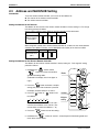
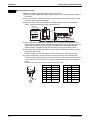
Address and MAIN/SUB Setting
Introduction
To set the wireless remote controller, you have to set the address for:
The receiver of the wireless remote controller
The wireless remote controller.
Setting the Address for the Receiver
The address for the receiver of the wireless remote controller is factory setting to 1. To change
this setting, proceed as follows:
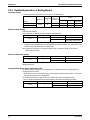
Set the wireless address switch (SS2) on the PCB according to the table below.
Unit No.
No. 1
No. 2
1
2
3
3
3
2
2
1
1
Wireless address
switch (SS2)
No. 3
When using both a wired and a wireless remote controller for 1 indoor unit, the wired controller
should be set to MAIN. Therefore, set the MAIN/SUB switch (SS1) of the receiver to SUB.
MAIN/SUB
MAIN
MAIN/SUB switch
(SS1)
SUB
S
S
M
M
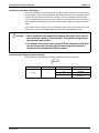
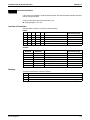
Setting the Address for the Wireless Remote Controller
The address for the wireless remote controller is factory setting to 1. To change this setting,
proceed as follows:
1. Hold down the “
“
/TEST
” button and the
” button for at least 4 seconds to
get the Field setting mode.
3
Mode
(Indicated in the display area in the figure at
right.)
FAN
2. Press the “
2
” button and select a multiple
setting (A/b). Each time the button is pressed
the display switches between “A” and “b”.
3. Press the “
” button or “
UP
” button to set
the address.
1
2
4
Address
DOWN
3
4
5
6
Multiple
setting
Address can be set from 1 to 6, but set it to 1 ~
3 and to same address as the receiver. (The
receiver does not work with address 4 ~ 6.)
1
5
RESERVE
4. Press the “
” button to enter the setting.
/TEST
5. Hold down the “
” button for at least 1 second to quit the Field setting mode and
return to the normal display.
24
Remote Controller
Service Mode
SiUS281117
3. Service Mode
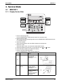
3.1
BRC1D71
3.1.1 Display Service Data
Unit No.
Mode No.
Second
Code No.
Field
Setting
Mode
First
Code No.
3
4
1 2 7
6
5
3
1. Enter the field setting mode.
Press the INSPECTION / TEST operation button for 4 seconds or more.
2. Enter the service mode.
After having entered the field setting mode, press the INSPECTION / TEST operation button
for 4 seconds or more.
3. Select the mode No.
Set the desired mode No. with the up/down temperature setting button.
4. Select the unit No.
Select the indoor unit No. set with the time mode ON/OFF button.
5. Select the desired error history No. or sensor data No. with “
” or “
” button.
6. Each data displays (Refer to the table below display)
7. Return to the normal operation mode.
Press the INSPECTION / TEST operation button once.
Mode
No.
Function
Error History
Content and Operation
Method
You can change the
history with the
programming time updown button.
Example of Remote Controller Display
Past error
code
UNIT No.
CODE
40
SETTING
Error history
1: Newest
3: Oldest
"00" displayed for 4 and subsequent.
Sensor Data
Display
41
Remote Controller
Select the display
thermistor with the
programming time updown button
Display thermistor
0: Remote controller
thermistor
1: Suction air thermistor
2: Heat exchanger
thermistor
Thermistor type
Temperature
UNIT No.
SETTING
25
SiUS281117
Service Mode
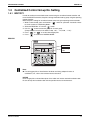
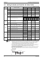
3.1.2 Service Setting
Mode No.
Unit No.
Mode No.
Second
Code No.
Field
Setting
Mode
First
Code No.
3
4
1 2 6
5
5
3
Field Setting Mode
Second Code No.
First Code No.
1. Enter the field setting mode.
Continue to press the INSPECTION / TEST operation button for a minimum of 4 seconds.
2. Enter the maintenance mode.
After having entered the field setting mode, continue to press the INSPECTION / TEST
operation button for a minimum of 4 seconds.
3. Select the mode No.
Set the desired mode No. with the up/down temperature setting button.
4. Select the unit No.
Select the indoor unit No. set with the time mode ON/OFF button.
5. Carry out the necessary settings for each mode. (Mode 43 only possible for wireless remote
controller)
• In case of Mode 43
Press timer ON/OFF button to decide the forced Fan ON.
• In case of Mode 44
Set “Fan speed” with fan speed control button and “Airflow direction” with airflow direction
adjusting button, then press timer ON/OFF button to decide.
• In case of Mode 45
Select the changed unit No. with “
” or “
” button, then press timer ON/OFF button to
decide.
6. Return to the normal operation mode.
Press the INSPECTION / TEST operation button 1 time.
26
Remote Controller
Service Mode
SiUS281117
Mode
No.
43
Function
Forced Fan
ON
Content and Operation
Example of Remote Controller Display
Method
Turns the fan ON for each unit
UNIT No.
individually.
SETTING
Individual
Setting
44
Sets fan speed and airflow
direction for each unit
individually when using group
control.
Settings are made using the
“airflow direction adjust” and
“fan speed adjust” buttons.
Fan
speed
45
0: Upper
Airflow direction
UNIT No.
CODE
Unit No.
Change
1 : Low
3 : High
Changes unit No.
Set the unit No. after changing
with the programming time updown button.
4: Lowest
SETTING
Field setting No.
No. after change
UNIT No.
CODE
Remote Controller
SETTING
27
SiUS281117
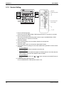
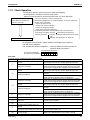
3.2
Service Mode
BRC1E71
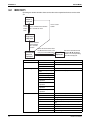
Operating the remote controller allows service data to be acquired and various services to be
set.
Basic
screen is
displayed.
Press
Cancel
button
once.
Press and hold Cancel button
for 4 seconds or more.
Press Cancel
button.
Service
settings menu
is displayed.
Press and hold
Cancel button
for 4 seconds
or more.
Select the desired item from
the Maintenance menu, and
then press Menu/OK button.
Maintenance
menu is
displayed.
Maintenance Menu
2.1. Model Name
2.2. Operating Hours
2.3. Indoor Unit Status
Press Cancel button.
Item 2
1. Unit No.
2. Indoor unit
3. Outdoor unit
1. Unit No.
2. Indoor unit operating
time
3. Indoor unit fan operation
4. Indoor unit energized time
5. Outdoor operating time
6. Outdoor unit fan 1
operation
7. Outdoor unit fan 2
operation
8. Outdoor comp. 1
operation
9. Outdoor comp. 2
operation
1. Unit No.
2. FAN
3. FLAP
4. Speed
5. EV
6. MP
7. EH
8. Hu
9. TBF
28
Item 2 is
displayed.
Select the desired Unit No.
using the / (Up/Down)
buttons. The corresponding
data will be displayed.
Remarks
Select the Unit No. you want to check.
Select the Unit No. you want to check.
All of these are displayed in hours.
Select the Unit No. you want to check.
Fan tap
Swing, fixed
Fan speed (rpm)
Degree that electronic expansion valve is open
(pls)
Drain pump ON/OFF
Electric heater ON/OFF
Humidifier ON/OFF
Anti-freezing control ON/OFF
Remote Controller
Service Mode
SiUS281117
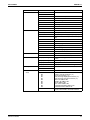
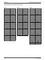
Maintenance Menu
2.3. Indoor Unit Status
Item 2
10.FLOAT
11.T1/T2
12.Unit No.
13.Th1
14.Th2
15.Th3
16.Th4
17.Th5
18.Th6
2.4. Outdoor Unit Status 1. Unit No.
2. FAN step
3. COMP
4. EV1
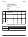
2.5. Forced Defrost
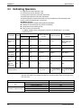
2.6. Error Display
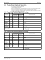
2.7. Swap Unit No.
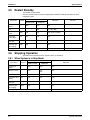
2.8. Addressed Sensor
Value
Remote Controller
5. SV1
6. Th1
7. Th2
8. Th3
9. Th4
10.Th5
11.Th6
1. Forced defrost ON
2. Forced defrost OFF
1. Display Warning ON
2. Display Warning OFF
3. Display Error ON
4. Display Error OFF
1. Current Unit No.
2. Transfer Unit No.
Unit No.: 0 - 15
Code
00:
01:
02:
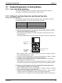
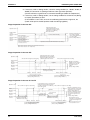
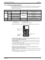
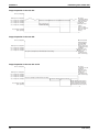
03:
04:
05:
06:
07:
08:
09:
Data
Remarks
Select the Unit No. you want to check.
Suction air thermistor
Heat exchanger thermistor
—
Discharge air thermistor
—
—
Select the Unit No. you want to check.
Fan tap
Compressor power supply frequency (Hz)
Degree that electronic expansion valve is open
(pls)
Solenoid valve ON/OFF
Outdoor air thermistor
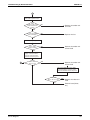
Heat exchanger thermistor
Discharge pipe thermistor
Heat exchanger deicer thermistor
Heat exchanger gas pipe thermistor
Liquid pipe thermistor
Enables the forced defrost operation.
Disables the forced defrost operation.
Displays a warning on the screen if an error
occurs.
No warning is displayed.
Displays the error on the screen.
Displays neither errors nor warnings.
A unit No. can be transferred to another.
Select the Unit No. you want to check.
Remote controller thermistor (°F)
Suction air thermistor (°F)
Heat exchanger liquid pipe thermistor (°F)
Heat exchanger gas pipe thermistor (°F)
Indoor unit address No.
Outdoor unit address No.
BS unit address No.
Zone control address No.
Cooling/Heating batch address No.
Demand/low-noise address No.
The corresponding data will be displayed,
based on the Unit No. and Code selected.
29
SiUS281117
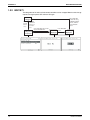
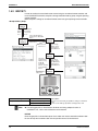
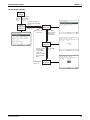
Inspection Mode
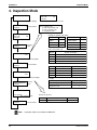
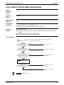
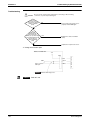
4. Inspection Mode
0
Unit
L0
Error code
Inspection
Error code blinks when an error occurs.
Normal display (No display)
INSPECTION/TEST Press the button.
operation
0 7 1...Capacity code
F...Indoor unit system code
C...Indoor unit type code
J...Progression code
0
L0
Unit
Error code
Inspection
Example of capacity code display
Inspection mode
INSPECTION/TEST Press the
button.
operation
Model
Display
FCQ18
056
FHQ18/FAQ18
Display
056
FCQ24
071
FHQ24/FAQ24
071
FHQ30
090
FHQ30
090
FBQ36
112
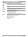
Model
Indoor unit system code
System classification
Display
071
FCJ
Indoor unit model code display
INSPECTION/TEST Press the button.
operation
1
(VAV indoor unit)
2
Outdoor air processing unit
F
Standard indoor unit
H
Ceiling suspended cassette
Indoor unit type code
Display
–––
AA1
Outdoor unit model code display
A
Wall mounted
FAQ
C
Multi flow
FCQ
H
Ceiling suspended
FHQ
J
Built-in
FBQ
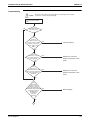
For FTQ
INSPECTION/TEST Press the
button.
operation
Test operation
Test operation mode
Indoor unit system code
E
Indoor unit type code
9
Progression code
1
Outdoor model code
Display
INSPECTION/TEST Press the button.
operation
Note:
30
Model
Type
A8F
Type
Split system
Model
RZQ-P, RZR-P
Inspection mode is not available for BRC1E71.
Remote Controller
SiUS281117
Part 4
Function and Control
1. Function General ..................................................................................32
1.1 Operation Mode ..................................................................................... 32
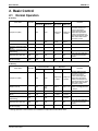
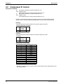
2. Basic Control.........................................................................................33
2.1
2.2
2.3
2.4
Normal Operation................................................................................... 33
Compressor PI Control .......................................................................... 34
Electronic Expansion Valve PI Control .................................................. 35
Cooling Operation Fan Control .............................................................. 36
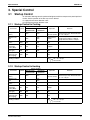
3. Special Control......................................................................................37
3.1
3.2
3.3
3.4
3.5
3.6
3.7
Startup Control ....................................................................................... 37
Oil Return Operation .............................................................................. 38
Defrosting Operation .............................................................................. 40
Pump Down Residual Operation............................................................ 41
Restart Standby ..................................................................................... 42
Stopping Operation ................................................................................ 42
Pressure Equalization Prior to Startup ................................................... 43
4. Protection Control .................................................................................44
4.1
4.2
4.3
4.4
High Pressure Protection Control .......................................................... 44
Low Pressure Protection Control ........................................................... 45
Discharge Pipe Protection Control ......................................................... 46
Inverter Protection Control ..................................................................... 47
5. Other Control ........................................................................................48
5.1 Heating Operation Prohibition ................................................................ 48
6. Outline of Control (Indoor Unit) .............................................................49
6.1
6.2
6.3
6.4
6.5
6.6
6.7
6.8
6.9
6.10
Function and Control
Drain Pump Control ............................................................................... 49
Louver Control for Preventing Ceiling Dirt ............................................. 51
Room Temperature Thermistor in Remote Controller............................ 52
Thermostat Control with Operation Mode Set to "AUTO" ...................... 54
Freeze-up Prevention ............................................................................ 55
View of Operations of Swing Flaps ........................................................ 56
Hot Start Control (In Heating Operation Only) ....................................... 57
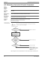
Heater Control (FTQ) ............................................................................. 59
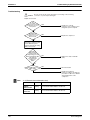
4 Step Thermostat Processing (FTQ) .................................................... 62
Interlocked with External Equipment (FTQ) ........................................... 63
31
SiUS281117
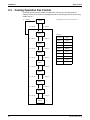
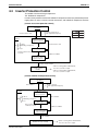
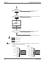
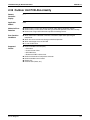
Function General
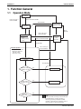
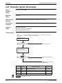
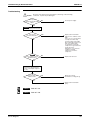
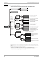
1. Function General
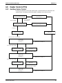
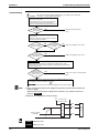
1.1
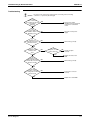
Operation Mode
Operation in
stop mode
Indoor unit stop or
thermostat OFF
Indoor unit thermostat ON
Error/Standby
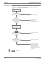
Restart standby
(Compressor stop)
Pressure
equalization
prior to startup
Error/
Standby
Indoor unit stop or
thermostat OFF
Startup control
• Cooling startup
control
• Heating startup
control
Indoor unit thermostat ON
Pump down
residual
operation
Error/Standby
Indoor unit stop or
thermostat OFF
Normal operation
• Compressor PI control
• Electronic expansion
valve PI control
• Protection control
Cooling or heating
operation
Error/Standby
Oil return starting
conditions are met.
Yes
Oil return operation
No
Defrost starting
conditions are met.
Yes
Defrosting operation
No
Operation
mode change
No
32
Yes
Note:
In the event indoor unit stops or the thermostat
turns OFF while in oil return operation or
defrosting operation, pump down residual
operation is performed on completion of the oil
return operation or defrosting operation.
Function and Control
Basic Control
SiUS281117
2. Basic Control
2.1
Normal Operation
Cooling
Parts Name
Symbol
Electric Symbol
Operation
RZR18/24/30P RZR36/42P
RZQ18/24/30P RZQ36/42P
RZR18/24/30P RZR36/42P
RZQ18/24/30P RZQ36/42P
Remarks
Compressor (INV.)
M1C
M1C
Outdoor unit fan
M1F
M1F
M2F
Used for high pressure
protection control, low
pressure protection
discharge pipe
Compressor Compressor control,
temperature
protection
PI control
PI control
control, and compressor
operating frequency upper
limit control with inverter
protection control.
Cooling fan Cooling fan
control
control
Four-way valve
20S1
Y1S
Y1S
OFF
OFF
Electronic expansion valve
(Main)
Electronic expansion valve
(Subcooling)
EV1
Y1E
Y1E
1400 pls
480 pls
EV3
Y3E
PI control
Solenoid valve (Hot gas)
SVP
Y2S
Y2S
OFF
OFF
This valve turns ON with
low pressure protection
control.
Solenoid valve (Receiver
gas discharging)
SVG
Y3S
OFF
Heating
Parts Name
Electric Symbol
Operation
RZQ18/24/30P RZQ36/42P
RZQ18/24/30P RZQ36/42P
Symbol
Remarks
Compressor (INV.)
M1C
M1C
Outdoor unit fan
M1F
M1F
M2F
Used for high pressure
protection control, low
pressure protection
discharge pipe
Compressor Compressor control,
temperature protection
PI control
PI control
control, and compressor
operating frequency upper
limit control with inverter
protection control.
The fan step changes to
STEP 8
Step 7 or 8 STEP 1 with high pressure
> 454 psi.
Four-way valve
20S1
Y1S
Y1S
ON
ON
Electronic expansion valve
(Main)
Electronic expansion valve
(Subcooling)
EV1
Y1E
Y1E
PI control
PI control
EV3
Y3E
PI control
Solenoid valve (Hot gas)
SVP
Y2S
Y2S
OFF
OFF
This valve turns ON with
low pressure protection
control.
Solenoid valve (Receiver
gas discharging)
SVG
Y3S
OFF
Heating operation is not functional at an outdoor air temperature of 82FDB or more.
Function and Control
33
SiUS281117
2.2
Basic Control
Compressor PI Control
Compressor PI Control
Te:
Low pressure equivalent saturation temperature (°F)
TeS: Target Te value
(Varies depending on Te setting, operating frequency, etc.)
Tc:
High pressure equivalent saturation temperature (°F)
TcS: Target Tc value
(Varies depending on Tc setting, operating frequency, etc.)
Carries out the compressor capacity PI control to maintain Te at constant during cooling
operation and Tc at constant during heating operation to ensure stable unit performance.
[Cooling]
Controls compressor capacity to adjust Te to achieve target value (TeS).
Te setting (Set in Set-up mode 2)
L
M (Normal)
H
(factory
setting)
37.5
43
48
[Heating]
Controls compressor capacity to adjust Tc to achieve target value (TcS).
Tc setting
L
M (Normal)
(factory
setting)
109.5
115
H
120
RZR18/24/30P, RZQ18/24/30P
STEP
Inverter
1
52Hz
2
57Hz
3
62Hz
4
68Hz
5
74Hz
6
81Hz
7
88Hz
8
96Hz
9
104Hz
10
110Hz
11
116Hz
12
124Hz
13
133Hz
14
143Hz
15
158Hz
16
165Hz
17
177Hz
Compressors may operate in a pattern other than those listed in above tables subject to the
operating conditions.
34
Function and Control
Basic Control
SiUS281117
RZR36/42P, RZQ36/42P
INV.
STn
(Full-load)
1
2
3
4
5
6
52.0Hz
7
57.0Hz
8
62.0Hz
9
68.0Hz
10
74.0Hz
INV.
(Unload)
36.0Hz
39.0Hz
43.0Hz
47.0Hz
52.0Hz
57.0Hz
64.0Hz
71.0Hz
78.0Hz
STn
11
12
13
14
15
16
17
18
19
20
INV.
(Full-load)
80.0Hz
86.0Hz
92.0Hz
98.0Hz
104.0Hz
110.0Hz
116.0Hz
122.0Hz
128.0Hz
134.0Hz
INV.
(Unload)
STn
21
22
23
24
25
26
27
28
29
30
31
INV.
(Full-load)
140.0Hz
146.0Hz
152.0Hz
158.0Hz
164.0Hz
170.0Hz
175.0Hz
180.0Hz
185.0Hz
190.0Hz
195.0Hz
INV.
(Unload)
Note:
Compressors may operate in a pattern other than those listed in above tables subject to the operating conditions.
Selection of full load operation to/from unload operation is made with the unload circuit solenoid valve (Y3S =
SVUL). The full load operation is performed with the SVUL set to OFF, while the unload operation is performed with
the SVUL set to ON.
2.3
Electronic Expansion Valve PI Control
Main Electronic Expansion Valve EV1 Control
Carries out the electronic expansion valve (Y1E) PI control to maintain the evaporator outlet
superheated degree (SH) at constant during heating operation to make maximum use of the
outdoor unit heat exchanger (evaporator).
SH = Ts1 - Te
SH: Evaporator outlet superheated degree
Ts1: Suction pipe temperature detected by
thermistor
Te: Low pressure equivalent saturation temperature
The optimum initial value of the evaporator outlet superheated degree is 9°F, but varies
depending on the discharge pipe superheated degree of inverter compressor.
Subcooling Electronic Expansion Valve EV3 Control
Makes PI control of the electronic expansion valve (Y3E) to keep the superheated degree (SH)
of the outlet gas pipe on the evaporator side for the full use of the subcooling heat exchanger.
SH = Tsh- Te
SH: Evaporator outlet superheated degree
Tsh: Suction pipe temperature detected by
thermistor
Te: Low pressure equivalent saturation
temperature
Function and Control
35
SiUS281117
2.4
Basic Control
Cooling Operation Fan Control
In cooling operation with low outdoor air temperature, this control is used to provide the
adequate amount of circulation air with liquid pressure secured by high pressure control using
outdoor unit fan.
Pc: High pressure sensor detection value
Pc > 450 psi
STEP 8
Pc < 261 psi
Pc > 348 psi
STEP 7
Pc < 261 psi
Fan Steps
Pc > 348 psi
STEP 6
Pc < 261 psi
Pc > 348 psi
STEP 5
Pc < 261 psi
Cooling
M1F
STEP 0
0 rpm
STEP 1
200 rpm
STEP 2
250 rpm
STEP 3
300 rpm
STEP 4
360 rpm
STEP 5
430 rpm
STEP 6
515 rpm
STEP 7
620 rpm
STEP 8
830 rpm
Pc > 348 psi
STEP 4
Pc < 261 psi
Pc > 348 psi
STEP 3
Pc < 261 psi
Pc > 334 psi
STEP 2
Pc < 261 psi
Pc > 305 psi
STEP 1
Pc < 261 psi
Pc > 276 psi
STEP 0
36
Function and Control
Special Control
SiUS281117
3. Special Control
3.1
Startup Control
On activation, following control is performed to lighten load of the compressor by back liquid and
the like. Also, the position of the four-way valve is defined.
Pc: High-pressure sensor detection value
Pe: Low-pressure sensor detection value
3.1.1 Startup Control in Cooling
Symbol
Electric Symbol
RZR18/24/32P
RZR36/42P
RZQ18/24/30P
RZQ36/42P
Compressor
(INV.)
M1C
Outdoor unit
fan
Four-way
valve
Electronic
expansion
valve (Main)
Solenoid valve
(Hot gas)
Solenoid valve
(Receiver gas
discharging)
Parts Name
Operation
Remarks
M1C
Differential
pressure control
M1F
M1F
M2F
High pressure
control
Compressor operating frequency
increases by 2 step / 20 seconds until
Pc – Pe > 58 psi.
Initial fan speed is set to STEP 0.
1-step increase with Pc > 305 psi
1-step decrease with Pc < 261 psi
20S1
Y1S
Y1S
OFF
EV1
Y1E
Y1E
1400 pls
SVP
Y2S
Y2S
ON
SVG
Y3S
OFF
OR
Ending conditions
230 seconds
Pc – Pe > 58 psi
& 45 seconds
3.1.2 Startup Control in Heating
Symbol
Electric Symbol
RZR18/24/32P
RZR36/42P
RZQ18/24/30P
RZQ36/42P
Compressor
(INV.)
M1C
Outdoor unit
fan
Four-way
valve
Electronic
expansion
valve (Main)
Solenoid valve
(Hot gas)
Solenoid valve
(Receiver gas
discharging)
Parts Name
Operation
Remarks
M1C
Differential
pressure control
Compressor operating frequency
increases by 2 step / 20 seconds until
Pc – Pe > 58 psi
M1F
M1F
M2F
STEP 8
20S1
Y1S
Y1S
ON
EV1
Y1E
Y1E
180 pls
SVP
Y2S
Y2S
ON
SVG
Y3S
OFF
Ending conditions
Function and Control
OR
145 seconds
Pc – Pe > 58 psi
& 15 seconds
37
SiUS281117
3.2
Special Control
Oil Return Operation
Oil flown from the compressor to the side of system is collected by oil return operation, in case
of that oil in the compressor runs down.
3.2.1 Oil Return Operation in Cooling
Tc: High pressure equivalent saturation temperature
Te: Low pressure equivalent saturation temperature
Ts: Suction pipe temperature detected by thermistor
[Conditions to start]
The cooling oil return operation is started referring following conditions.
Integrated amount of displaced oil
Timer
(After the power is turned ON, integrated operating-time is 2 hours and subsequently every 8
hours.)
In addition, integrated amount of displaced oil is derived from Tc, Te, and the compressor
load.
Parts Name
Compressor
(INV.)
Symbol
Electric Symbol
RZR18/24/32P
RZR36/42P
RZQ18/24/30P
RZQ36/42P
Oil return
preparation
operation
Oil return operation
Post-oil-return
operation
M1C
M1C
Upper limit
control
124 Hz
124 Hz
Outdoor unit fan
M1F
Fan control
Fan control
Fan control
Four-way valve
Electronic
expansion valve
(Main)
Solenoid valve
(Hot gas)
Solenoid valve
(Receiver gas
discharging)
20S1
Y1S
M1F
M2F
Y1S
OFF
OFF
OFF
EV1
Y1E
Y1E
1400 pls
1400 pls
1400 pls
SVP
Y2S
Y2S
OFF
ON
ON
SVG
Y3S
OFF
OFF
OFF
20 seconds
OR
Ending conditions
Indoor unit actuator
Thermostat ON unit
Fan
Stopping unit
Thermostat OFF unit
Thermostat ON unit
Electronic expansion valve
Stopping unit
Thermostat OFF unit
38
6 minutes
Ts – Te < 9°F
3 minutes
Cooling oil return operation
Set air volume
OFF
OFF
Normal opening
200 pls
200 pls
Function and Control
Special Control
SiUS281117
3.2.2 Oil Return Operation in Heating
Pc: High-pressure sensor detection value
Pe: Low-pressure sensor detection value
Tc: High-pressure equivalent saturation temperature
Te: Low-pressure equivalent saturation temperature
Ts: Suction pipe temperature detected by thermistor
[Conditions to start]
The heating oil return operation is started referring following conditions.
Integrated amount of displaced oil
Timer
(After the power is turned ON, integrated operating-time is 2 hours and subsequently every 8
hours.)
In addition, integrated amount of displaced oil is derived from Tc, Te, and the compressor
load.
Electric Symbol
Parts Name Symbol RZR18/24/32P
RZR36/42P
RZQ18/24/30P
RZQ36/42P
Oil return preparation
operation
Compressor
(INV.)
M1C
M1C
Upper limit control
124 Hz
2-step increase from
52 Hz to (Pc – Pe >
58 psi) time
Outdoor unit
fan
Four-way
valve
Electronic
expansion
valve (Main)
Solenoid
valve (Hot
gas)
Solenoid
valve
(Receiver
gas
discharging)
M1F
M1F
M2F
STEP 8
OFF
STEP 8
20S1
Y1S
Y1S
ON
OFF
ON
EV1
Y1E
Y1E
SH control
1400 pls
200~400 pls
SVP
Y2S
Y2S
OFF
ON
ON
SVG
Y3S
ON
ON
OFF
130 seconds
OR Ts – Te < 9°F OR Pc – Pe > 58 psi
Ending conditions
Post-oil-return
operation
Oil return operation
6 minutes
160 seconds
From the preparing oil return operation to the oil return operation, and from the oil return
operation to the operation after oil return, the compressor stops for 1 minute to reduce noise
on changing of the four-way valve.
Indoor unit actuator
Thermostat ON unit
Fan
Stopping unit
Thermostat OFF unit
Thermostat ON unit
Electronic expansion valve
Stopping unit
Thermostat OFF unit
Function and Control
Heating oil return operation
OFF
OFF
OFF
500 pls
500 pls
500 pls
39
SiUS281117
3.3
Special Control
Defrosting Operation
Pc: High-pressure sensor detection value
Pe: Low-pressure sensor detection value
Tc: High-pressure equivalent saturation temperature
Te: Suction pipe equivalent saturation temperature
The defrost operation is performed to solve frost on the outdoor unit heat exchanger when
heating, and the heating capacity is recovered.
[Conditions to start]
The defrost operation is started referring following conditions.
Outdoor unit heat exchanger heat transfer co-efficiency
Temperature of heat exchanger (Tb)
Timer (2 hours at the minimum)
In addition, outdoor unit heat exchanger co-efficiency is derived from Tc, Te, and the
compressor load.
Electric Symbol
Parts Name Symbol RZR18/24/32P
RZR36/42P
RZQ18/24/30P
RZQ36/42P
Defrost preparation
operation
Post Defrost
operation
Defrost operation
Compressor
(INV.)
M1C
M1C
52 Hz
177 Hz
2-step increase from
52 Hz to (Pc – Pe >
58 psi) every 20
seconds
Outdoor unit
fan
M1F
M1F
M2F
STEP 8
OFF
STEP 8
Four-way
valve
Y1S
Y1S
ON
OFF
ON
Electronic
expansion
EV1
valve (Main)
Y1E
Y1E
SH control
1400 pls
200~400 pls
Solenoid
valve (Hot
gas)
SVP
Y2S
Y2S
OFF
ON
ON
Solenoid
valve
(Receiver
SVG
gas
discharging)
Y3S
ON
ON
OFF
130 seconds
OR Tb > 51.8F
20S1
Ending conditions
15 minutes
160 seconds
OR Pc – Pe > 58 psi
From the preparing operation to the defrost operation, and from the defrost operation to the
operation after defrost, the compressor stops for 1 minute to reduce noise on changing of the
four-way valve.
Indoor unit actuator
Thermostat ON unit
Fan
Stopping unit
Thermostat OFF unit
Thermostat ON unit
Electronic expansion valve
Stopping unit
Thermostat OFF unit
40
During defrost
OFF
OFF
OFF
500 pls
500 pls
500 pls
Function and Control
Special Control
3.4
SiUS281117
Pump Down Residual Operation
Pe: Low pressure sensor detection value
Td: Discharge pipe temperature
When activating compressor, if the liquid refrigerant remains in the heat-exchanger, the liquid
enters into the compressor and dilutes oil therein resulting in decrease of lubricity.
Therefore, the pump down residual operation is performed to collect the refrigerant in the heatexchanger when the compressor is down.
3.4.1 Pump Down Residual Operation in Cooling
Electric Symbol
Parts Name
Symbol
RZR18/24/32P
RZQ18/24/30P
Master unit operation
Compressor
(INV.)
M1C
M1C
124 Hz
Outdoor unit
fan
M1F
M1F
M2F
Fan control
Four way
valve
20S1
Y1S
Y1S
OFF
Electronic
expansion
valve (Main)
EV1
Y1E
Y1E
2000 pls
Solenoid valve
(Hot gas)
SVP
Y2S
Y2S
OFF
Solenoid valve
(Receiver gas
discharging)
SVG
Y3S
ONOFF
RZR36/42P
RZQ36/42P
30 seconds
OR Pe < 73 psi
Ending conditions
Td > 230F
3.4.2 Pump Down Residual Operation in Heating
Electric Symbol
Parts Name
Symbol
RZR18/24/32P
RZQ18/24/30P
Master unit operation
Compressor
(INV.)
M1C
M1C
124 Hz
Outdoor unit
fan
M1F
M1F
M2F
STEP 8
Four way
valve
20S1
Y1S
Y1S
ON
Electronic
expansion
valve (Main)
EV1
Y1E
Y1E
0 pls
Solenoid valve
(Hot gas)
SVP
Y2S
Y2S
OFF
Solenoid valve
(Receiver gas
discharging)
SVG
Y3S
ONOFF
RZR36/42P
RZQ36/42P
3 minutes
Ending conditions
Function and Control
OR Pe < 36 psi
Td > 230F
41
SiUS281117
3.5
Special Control
Restart Standby
Ta: Outdoor air temperature
Restart is stood by force to prevent frequent power-ON/OFF and to equalize pressure in the
refrigerant system.
Electric Symbol
Parts Name
Symbol
RZR18/24/32P
RZQ18/24/30P
Compressor
(INV.)
M1C
M1C
OFF
Outdoor unit
fan
M1F
M1F
M2F
Ta > 86F: STEP 4
Ta 86F: OFF
Four-way
valve
20S1
Y1S
Y1S
Keep former condition.
Electronic
expansion
valve (Main)
EV1
Y1E
Y1E
0 pls
Solenoid valve
(Hot gas)
SVP
Y2S
Y2S
ON
Solenoid valve
(Receiver gas
discharging)
SVG
Y3S
OFF
5 minutes
Ending conditions
3.6
Operation
RZR36/42P
RZQ36/42P
Remarks
Stopping Operation
Operation of the actuator when the system is down, is cleared up.
3.6.1 When System is in Stop Mode
Electric Symbol
Parts Name
Symbol
RZR18/24/32P
RZQ18/24/30P
Operation
RZR36/42P
RZQ36/42P
Compressor
(INV.)
M1C
M1C
OFF
Outdoor unit fan
M1F
M1F
M2F
OFF
Four-way valve
20S1
Y1S
Y1S
Keep former condition.
Electronic
expansion valve
(Main)
EV1
Y1E
Y1E
0 pls
Solenoid valve
(Hot gas)
SVP
Y2S
Y2S
OFF
Solenoid valve
(Receiver gas
discharging)
SVG
Y3S
OFF
Ending conditions
42
Indoor unit thermostat is turned ON.
Function and Control
Special Control
3.7
SiUS281117
Pressure Equalization Prior to Startup
Ta: Outdoor air temperature
Pc: High-pressure sensor detection value
Pe: Low-pressure sensor detection value
Before activating the compressor, the activation load is lightened by equalization across the
compressor. In addition, inverters turn ON electricity and capacitors are charged.
Electric Symbol
Parts Name
Symbol
RZR18/24/32P
RZQ18/24/30P
Compressor
(INV.)
M1C
M1C
OFF
Outdoor unit
fan
M1F
M1F
M2F
Cooling: OFF
Heating: Ta > 78.8°F; STEP 8,
Ta 78.8°F; OFF
Four-way
valve
20S1
Y1S
Y1S
Keep former condition.
Electronic
expansion
valve (Main)
EV1
Y1E
Y1E
0 pls
Solenoid valve
(Hot gas)
SVP
Y2S
Y2S
ON
Solenoid valve
(Receiver gas
discharging)
SVG
Y3S
OFF
Ending conditions
Function and Control
Operation
RZR36/42P
RZQ36/42P
OR
3 minutes
Pc – Pe < 29 psi
Remarks
43
SiUS281117
Protection Control
4. Protection Control
4.1
High Pressure Protection Control
Pc: High-pressure sensor detection value
This high pressure protection control is used to prevent the activation of protection devices due
to abnormal increase of high pressure and to protect compressors against the transient
increase of high pressure.
[Cooling]
Pc > 505 psi
High pressure not limited
&
• Inverter upper limit frequency
• Pc ≤ 483 psi
• During oil return operation
• After oil return operation
• Stopping operation
• Heating operation
OR
High pressure limited
INV. upper limit frequency:
1-step down from current
compressor frequency
Every 10 sec.
Pc > 526 psi
Pc > 512 psi
57Hz
Keeping the current step
10 sec.
Pc < 490 psi
490 psi ≤ Pc ≤ 505 psi
Every 60 sec.
INV. upper limit frequency:
1-step up from current
compressor frequency
Every
5 min.
INV. upper limit frequency:
1-step up from current error
frequency
Pc > 547 psi
When occurring 3 times within 30
minutes, S1PH (High pressure switch) is
activated without high pressure standby,
thus outputting the error code "E3".
High pressure
standby
[Heating]
High pressure drop
High pressure not limited
Pc > 469 psi
Pc < 441 psi
High pressure
limited
57Hz
Pc > 527 psi
High pressure
standby
44
When S1PH (High pressure switch) is
activated, the error code "E3" is output.
Function and Control
Protection Control
4.2
SiUS281117
Low Pressure Protection Control
Pe: Low pressure sensor detection value
This low pressure protection control is used to protect compressors against the transient
decrease of low pressure.
[Cooling]
Low pressure not limited
Pe < 36 psi
Pe > 57 psi
Low pressure
limited
57Hz
Pe < 10 psi
Low pressure
standby
When occurring 3 times within 60 min.,
the error code "E4" is output.
[Heating]
• Pe > 36 psi
& • Inverter upper limit
frequency
SVP: Solenoid valve (Hot gas)
Low pressure not limited
Pe < 23 psi
Low pressure limited
&
Upper limit:
145.5Hz
More than 145.5Hz
Pe < 23 psi
Pe < 19 psi
Pe < 19 psi
Upper limit:
57Hz
Pe > 28 psi
Upper limit: 1-step up from
current compressor frequency
Pe > 28 psi (every 20 sec.)
Pe > 25 psi
SVP = OFF
SVP = ON
Pe < 15 psi
Pe < 10 psi
Low pressure
standby
Function and Control
When occurring 3 times within 60 min.,
the error code "E4" is output.
45
SiUS281117
4.3
Protection Control
Discharge Pipe Protection Control
HTdi: Value of INV. compressor discharge pipe temperature (Tdi) compensated with outdoor air
temperature
Tp: Value of compressor port temperature calculated by Tc and Te, and suction superheated
degree.
This discharge pipe protection control is used to protect the compressor internal temperature
against an error or transient increase of discharge pipe temperature.
[INV. compressor]
Discharge pipe protection control not limited
&
&
OR
• HTdi > 221˚F
• Tp > 266˚F
• Not during defrost operation
(preparation ~ post operation)
• Not during oil return operation in heating
(preparation ~ post operation)
• Not during oil return operation in cooling
(without preparation and post operation)
OR
• HTdi < 203˚F
• Tp < 212˚F
• Inverter upper limit Frequency.
• Defrost operation
(preparation ~ post operation)
• Oil return operation in heating
(preparation ~ post operation)
• Oil return operation in cooling
(without preparation and post operation)
In discharge pipe protection control
Inverter frequency 1-step down from
current compressor frequency
(lower limit: 57Hz)
30 sec.
OR
Inverter upper limit frequency:
1-step up from current compressor
frequency
Cooling: 20 sec.
Heating: 60 sec.
• HTdi > 230˚F
• Tp > 266˚F
&
• HTdi < 212˚F
• Tp < 239˚F
Keep the current step
Exclusion of
the right
conditions
OR
• HTdi > 266˚F
• HTdi > 239˚F for 90 sec. or more
• Tp > 284˚F
Fix Inverter frequency 57Hz
OR
• HTdi > 275˚F
• HTdi > 248˚F for 10 min. or more.
Discharge pipe
temp. control standby
46
When occurring 3 times within 100 min., the
error code "F3" is output.
Function and Control
Protection Control
4.4
SiUS281117
Inverter Protection Control
Tb: Outdoor unit heat exchanger temperature
Tfin: Radiation fin temperature
Inverter current protection control and radiation fin temperature control are performed to prevent
tripping due to an error, or transient inverter overcurrent, and radiation fin temperature increase.
[Inverter overcurrent protection control]
Not limited
&
Inverter current > X A
Limited
OR
• Inverter current ≤ X A
• INV. upper limit frequency
XA
Tb ≥ 77˚F
13.7
Tb < 77˚F
12.7
INV. upper limit frequency:
1-step down from current
compressor frequency
• 10 sec.
& • Matching of frequency
Inverter current > X A
• 15 sec.
Status quo
Inverter current ≤ X A continues
for 3 min.
Without conditions
INV. upper limit frequency:
1-step up from current
compressor frequency
Inverter current ≥ 24.9A
• When occurring 3 times within 60 min.,
the error code "L8" is output.
• When occurring 4 times within 60 min.,
the error code "L9" is output.
Inverter current
standby
[Inverter radiation fin temperature control]
Not limited
Tfin ≥ 179.6˚F
Limited
OR
&
&
• Tfin < 174.2˚F
• INV. upper limit frequency
INV. upper limit frequency:
1-step down from current
compressor frequency
Tfin ≥ 179.6˚F
• 10 sec.
• Matching of frequency
• 15 sec.
Status quo
Tfin ≤ 174.2˚F
continues for 3 min.
Without conditions
INV. upper limit frequency:
1-step up from current
compressor frequency
Tfin ≥ 180˚F
Radiation fin temp. standby
Function and Control
• When occurring 3 times within 60 min.,
the error code "L4" is output.
47
SiUS281117
Other Control
5. Other Control
5.1
Heating Operation Prohibition
Heating operation is prohibited above 82°FDB outdoor air temperature.
48
Function and Control
Outline of Control (Indoor Unit)
SiUS281117
6. Outline of Control (Indoor Unit)
6.1
Drain Pump Control
The drain pump is controlled by the ON/OFF buttons (4 button (1) - (4) given in the figure
below).
6.1.1 When the Float Switch is Tripped while the Cooling Thermostat is
ON:
Remote controller "A3" blinking abnormal
stop
ON
Thermostat
(running) OFF
OFF
Float switch
ON
ON
Drain pump
OFF
5 min.
5 min. 5 sec.
∗1) Normal operation
Note:
∗2) Error residual
1. (Normal operation):
The objective of residual operation is to completely drain any moisture adhering to the fin of
the indoor unit heat exchanger when the thermostat goes OFF during cooling operation.
2. (Error residual):
The remote controller will display "A3" and the air conditioner will come to an abnormal stop
in 5 minutes if the float switch is turned OFF while the cooling thermostat is ON.
6.1.2 When the Float Switch is Tripped while the Cooling Thermostat is
OFF:
Enters error treatment if the float switch is not reset within 5 minutes.
Thermostat
(running)
Remote controller "A3" blinking abnormal stop
ON
OFF
OFF
Float switch
ON
Drain pump
ON
OFF
5 min.
5 sec. 5 min.
5 sec.
∗3
Note:
3. (Error residual):
The remote controller will display "A3" and the air conditioner will come to an abnormal stop
if the float switch is turned OFF and not turned ON again within 5 minutes while the cooling
thermostat is OFF.
Function and Control
49
SiUS281117
Outline of Control (Indoor Unit)
6.1.3 When the Float Switch is Tripped during Heating Operation:
Remote controller "A3" blinking abnormal stop
Thermostat ON
(running)
OFF
ON
Humidifier
OFF
Reset
OFF
Float switch
ON
ON
Drain pump
OFF
5 min.
Note:
5 sec. 5 min.
During heating operation, if the float switch is not reset even after the 5 minutes operation, 5
seconds stop, 5 minutes operation cycle ends, operation continues until the switch is reset.
6.1.4 When the Float Switch is Tripped and “AF” is Displayed on the
Remote Controller:
Enters error treatment if the
float switch is not reset within
5 minutes.
ON
Remote controller
display
OFF
Float switch
Remote controller "A3" blinking
abnormal stop
OFF
ON
Drain pump
"AF" display (running)
1st time
2nd time
3rd time
∗4
∗4
4th time
5th time
ON
OFF
∗4: 5 min.
Note:
50
∗4
∗4
∗5
∗4
∗4
5 sec.
∗4
∗6
5. (Error residual):
If the float switch is tripped 5 times in succession, a drain error is determined to have
occurred. “AF” is then displayed as operation continues.
6. (Error residual):
The remote controller will display "A3" and the air conditioner will come to an abnormal stop
if the float switch is OFF for more than 5 minutes in the case of 5.
Function and Control
Outline of Control (Indoor Unit)
6.2
SiUS281117
Louver Control for Preventing Ceiling Dirt
We have added a control feature that allows you to select the range of in which air direction can
be adjusted in order to prevent the ceiling surrounding the air discharge outlet of ceiling
mounted cassette type units from being soiled.
Existing position
P0
P1
P2
P3
P4
Ceiling soiling prevention
position
Standard Setting
position
Draft prevention position
(Not for Multi flow type)
P0
P0
P1
P1
P3
P4
P4
P4'
P0
P1
P2
P2
P0'
P1'
P2'
P2
Draft
prevention
position
P0
P4
P3'
P3
P4
P0''
P1''
P2''
P3''
P4''
Same as existing position
Range of direction adjustment
Standard
position
Prohibited
P0'
P1'
P2'
P3'
P4'
Separated into 5 positions
(P1 - 4)
Range of direction adjustment
Dirt
prevention
position
Prohibited
P0''
P1''
P2''
P3''
P4''
Separated into 5 positions
(P2 - 4)
The factory setting position is standard position.
Function and Control
51
SiUS281117
6.3
Outline of Control (Indoor Unit)
Room Temperature Thermistor in Remote Controller
Temperature is controlled by both the room temperature thermistor in remote controller and
suction air thermistor () in the indoor unit. (This is however limited to when the field setting for
the room temperature thermistor in remote controller is set to “Use.”)
Note:
Cooling
When outdoor air is introduced to the air conditioner with mixed into indoor air, the room
temperature may fail to be set temperature, since TS and TH1 do not enter the area of “use
range of remote control thermistor.” In such a case, put the remote sensor (optional accessory)
in your room, and use it with setting “do not use remote control thermostat.”
For FTQ: Remote sensor (Optional accessory)
If there is a significant difference in the set temperature and the suction air temperature, fine
adjustment control is carried out using suction air thermistor () in the indoor unit, or using the
room temperature thermistor in the remote controller near the position of the user when the
suction air temperature is near the set temperature.
˚F
Set temperature
(Ts)
90
86
82
79
75
72
68
64
60
54
57
60
64
68
72
75
79
82
86
90
93
˚F
Suction air temperature (TH1)
Range in which room temperature
thermistor in remote controller can
be used
Range in which suction
air thermistor (∗) can be
used
Differential
Ex: When cooling
Assuming the set temperature in the figure above is 75°F, and the suction air
temperature has changed from 64°F to 86°F (A F):
(This example also assumes there are several other air conditioners, the system is OFF, and
that temperature changes even when the thermostat is OFF.)
Suction air thermistor () is used for temperatures from 64°F to 73°F (A C).
Room temperature thermistor in remote controller is used for temperatures from 73°F to 81°F
(C E).
Suction air thermistor () is used for temperatures from 81°F to 86°F (E F).
And, assuming suction air temperature has changed from 86°F to 64°F (F A):
Suction air thermistor () is used for temperatures from 86°F to 77°F (F D).
Room temperature thermistor in remote controller is used for temperatures from 77°F to 70°F
(D B).
Suction air thermistor () is used for temperatures from 70°F to 64°F (B A).
Note:
52
For FTQ: Remote sensor (Optional accessory)
Function and Control
Outline of Control (Indoor Unit)
Heating
SiUS281117
When heating, the hot air rises to the top of the room, resulting in the temperature being lower
near the floor where the occupants are. When controlling by suction air thermistor () only, the
unit may therefore be turned OFF by the thermostat before the lower part of the room reaches
the set temperature. The temperature can be controlled so the lower part of the room where the
occupants are does not become cold by widening the range in which room temperature
thermistor in remote controller can be used so that suction air temperature is higher than the set
temperature.
˚F
90
Set temperature
(Ts)
86
82
79
75
72
68
64
60
54
57
60
64
68
72
75
79
82
86
90
93
˚F
Suction air temperature (TH1)
Range in which room temperature
thermistor in remote controller can
be used
Range in which suction
air thermistor (∗) can be
used
Differential
Ex: When heating
Assuming the set temperature in the figure above is 75°F, and the suction air
temperature has changed from 64°F to 82°F (A D):
(This example also assumes there are several other air conditioners, the system is OFF, and
that temperature changes even when the thermostat is OFF.)
Suction air thermistor () is used for temperatures from 64°F to 77°F (A C).
Room temperature thermistor in remote controller is used for temperatures from 77°F to 82°F
(C D).
And, assuming suction air temperature has changed from 82°F to 64°F (D A):
Room temperature thermistor in remote controller is used for temperatures from 82°F to 73°F
(D B).
Suction air thermistor () is used for temperatures from 73°F to 64°F (B A).
Note:
Function and Control
For FTQ: Remote sensor (Optional accessory)
53
SiUS281117
6.4
Outline of Control (Indoor Unit)
Thermostat Control with Operation Mode Set to "AUTO"
When the operation mode is set to "AUTO" on the remote controller, the system will conduct the
temperature control shown below.
Furthermore, setting changes of the differential value (D°F) can be made according to
information in the "Field settings from remote controller (P.70 and later)" section.
Mode
No.
Second code No.
First code
No.
Contents of setting
4
Differential value while in "AUTO"
operation mode
12
01
02
03
04
05
06
07
08
0°F 1.8°F 3.6°F 5.4°F 7.2°F 9.0°F 10.8°F 12.6°F
: Factory setting
Set heating temperature
Set cooling temperature
A°F
D°F
Cooling thermostat ON
Cooling thermostat OFF
Display change
Cooling ® Heating
Display change
Heating ® Cooling
Heating thermostat OFF
Heating thermostat ON
5.4°F
(D
+ 3.6)°F
2
(Ex.) When automatic cooling temperature is set to 80.6°F:
Differential value :0°F
Differential value set to 7.2°F
Set heating temp.
Set cooling/
heating temp.
77°F
80.6°F
73.4°F
86°F
Cooling mode
Set cooling temp.
80.6°F
78.8°F
Control temp.
Heating mode
Control temp.
Heating mode
Differential value set to 1.8°F
Set heating temp.
78.8°F
76.1°F
Differential value set to 9°F
Set cooling temp.
80.6°F
84.2°F
Cooling mode
Set heating temp.
Set cooling temp.
71.6°F
80.6°F
72.5°F 77°F
Control temp.
Heating mode
Set heating temp.
77°F
75.2°F
Control temp.
Differential value set to 10.8°F
Set cooling temp.
80.6°F
82.4°F
Cooling mode
Set heating temp.
69.8°F
71.6°F 75.2°F
Set cooling temp.
80.6°F
Cooling mode
Control temp.
Heating mode
Set heating temp.
75.2°F
74.3°F
Control temp.
Heating mode
Differential value set to 5.4°F
Differential value set to 12.6°F
Set heating temp.
Set cooling temp.
80.6°F
Cooling mode
68°F
70.7°F 73.4°F
Control temp.
54
Cooling mode
Heating mode
Differential value set to 3.6°F
Heating mode
Cooling mode
Set cooling temp.
80.6°F
Cooling mode
Control temp.
Heating mode
Function and Control
Outline of Control (Indoor Unit)
6.5
SiUS281117
Freeze-up Prevention
Freeze-up
Prevention by Off
Cycle (Indoor
Unit)
When the temperature detected by liquid pipe temperature thermistor (R2T) of the indoor unit
heat exchanger drops too low, the unit enters freeze-up prevention operation in accordance with
the following conditions, and is also set in accordance with the conditions given below.
When freeze-up prevention is activated, the electronic expansion valve is closed, the drain
pump turns ON and the fan tap is fixed to L airflow. When the following conditions for stopping
are satisfied, it returns.
Conditions for starting freeze-up prevention: Temperature is 30.2°F or less for total of 40 min.,
or temperature is 23°F or less for total of 10 min.
Conditions for stopping freeze-up prevention: Temperature is 44.6°F or more for 10 min.
continuously
10 min.
44.6ºF
32ºF
23ºF
Freeze-up prevention operation
Forced OFF by thermostat
10 min.
OR
10 min.
44.6ºF
32ºF
30.2ºF
Freeze-up prevention operation
Forced OFF by thermostat
t1
t2
t3
t4
t > 40 min.
[Conditions for starting when airflow direction is 2-way or 3-way]
Conditions for starting: Temperature is 33.8ºF or less for a total of 15 minutes or 32ºF or less for
1 minute continuously.
10 min.
44.6ºF
32ºF
Freeze-up prevention operation
Forced OFF by thermostat
1 min.
OR
10 min.
44.6ºF
33.8ºF
Freeze-up prevention operation
Forced OFF by thermostat
t1
Function and Control
t2
t3
t4
t > 15 min.
55
SiUS281117
6.6
Outline of Control (Indoor Unit)
View of Operations of Swing Flaps
Swing flaps work as following.
Fan
OFF
OFF
OFF
OFF
Level
Level
Level
Level
Level
Level
LL
LL
Level
Level
Level
Level
Level
Level
LL
Level
Level
Level
LL
Level
Level
Level
Swinging
Setting the airflow
direction
Swinging
Thermostat of
Setting
the airflow
program dry is ON
direction
Swinging
Thermostat of
program dry is OFF Setting the airflow
direction
Swinging
Cooling thermostat
Setting the airflow
is OFF
direction
Swinging
Halt
Setting the airflow
direction
Swinging
Micro-computer is
controlled (including Setting the airflow
the cooling state)
direction
OFF
Level
Level
Level
OFF
Level
Level
Level
L1
Swinging
Swinging
Swinging
L1
Set up
Set up
Set up
OFF
or
L
Swinging
Swinging
Swinging
Set up
Set up
Set up
Set up
Swinging
Swinging
Swinging
Set up
Set up
Set up
Set up
OFF
Level
Level
Level
OFF
Set up
Level
Level
L
Swinging
Swinging
Swinging
L
Set up
Set up
Set up
Defrosting
Heating
FAQ
Level
Level
Swinging
Setting the airflow
direction
Swinging
Setting the airflow
direction
Swinging
Setting the airflow
direction
Swinging
Setting the airflow
direction
Hot-start from
defrosting
Thermostat is OFF
Hot-start from the
state that the
thermostat is OFF
Halt
Cooling
Flap Control
FHQ
Level
Level
FCQ
Level
Level
1. Only in FCQ case, L or LL.
56
Function and Control
Outline of Control (Indoor Unit)
6.7
SiUS281117
Hot Start Control (In Heating Operation Only)
At startup with thermostat ON or after the completion of defrosting in heating operation, the
indoor unit fan is controlled to prevent cold air from blasting out and ensure startup capacity.
[Detail of operation]
When either the start condition 1 or the start condition 2 is established, the operations shown
below will be conducted.
Defrost ending or oil return ending
or Thermostat ON
Hot start control
Hot start ending conditions
· lapse of 3 minutes
OR · [TH2] > 93.2˚F
· "Tc" > 125.6˚F
Hot start in progress
Normal control
Fan
H/L remote
controller setting
LL
Louver
OFF
Remote controller
setting
The fan is not OFF before initiating the hot start: LL
The fan is OFF before initiating the hot start: OFF
Normal control
Po (Horizontal)
TH2: Temperature detected with the gas thermistor
TC: High pressure equivalent saturated temperature
Function and Control
57
SiUS281117
Outline of Control (Indoor Unit)
FTQ
At startup with thermostat ON or after the completion of defrosting in heating operation, the
indoor unit fan is controlled to prevent cold air from blasting out and ensure startup capacity.
[Detail of operation]
When either the start condition 1 or the start condition 2 is established, the operations shown
below will be conducted.
Hot start start conditions
· Start condition 1: Defrost ending or
OR
oil return ending
· Start condition 2: Thermostat ON
Hot start control
Hot start ending conditions
• lapse of 3 minutes
OR • TH2 > 93˚F
• Tc > 126˚F
Hot start in progress
Hot start delay
30 sec.
Normal control
Fan
H/L remote
controller setting
LL
The fan is not OFF before initiating the hot start: LL
The fan is OFF before initiating the hot start: OFF
OFF
Humidifier
Heater
Normal control
ON
OFF
Normal control
ON
The fan is ON: ON
The fan is OFF: OFF
OFF
TH2: Temperature detected with the gas thermistor
TC: High pressure equivalent saturated temperature
58
Function and Control
Outline of Control (Indoor Unit)
6.8
SiUS281117
Heater Control (FTQ)
6.8.1 Auxiliary Heater Control
If heating is insufficient in heat pump system alone, an electrical heater is to be used as the
auxiliary heater. The following shows the ON/OFF conditions for the electric heater.
Fan H tap
120 seconds ∗2
Thermostat OFF/Stop operation
• Thermostat OFF
• Stop operation
Thermostat OFF
Thermostat step 1
Heat Pump: Fan normal operation
Fan H tap
120 seconds ∗2
Condition A
Timer clear
Continues for 5 minutes
Electrical heater step setting 01
Heater 1 ON
Heater 2 OFF
Fan H tap ∗1
Elimination of Condition A
Thermostat step 3 = "ON"
Continues for 5 minutes
Timer clear
Thermostat step 3 = "OFF"
Heater 1 ON
Heater 2 ON
Fan H tap ∗1
Elimination of Condition A
Thermostat step 4 = "ON"
Continues for 5 minutes
Timer clear
Thermostat step 4 = "OFF"
Heater 1 ON
Heater 2 ON
Fan H tap ∗1
Function and Control
Elimination of Condition A
59
SiUS281117
Outline of Control (Indoor Unit)
Condition A
&
Note:
• Thermostat step 2 = "ON"
• Heating mode
• Not during test operation
• Not during control operation
• High pressure condition = "ON" ∗3
• Liquid pipe temperature condition = "ON" ∗4
• Electrical heater setting = "3"
1: Fixing of the fan H tap
2: The operation should continue for a certain period of time after the heater turns OFF.
3: High pressure condition
ON
Thermostat
OFF
40
45
(˚F)
4: Liquid pipe temperature condition
ON
Thermostat
OFF
37
60
40
(˚F)
Function and Control
Outline of Control (Indoor Unit)
SiUS281117
6.8.2 Heat Pump Lockout Mode
During heating operation, users can select an electrical heater for heating. For this, signals are
sent using ABC terminal of outdoor unit PCB.
When the hot-water heating signal is received from the outdoor unit PCB, heating operation is
performed only with the heater as manual backup operation. The ON/OFF conditions for this
electrical heater are shown below.
Fan H tap
120 seconds ∗3
Thermostat OFF/Stop operation
• Thermostat OFF
• Stop operation
Thermostat ON
Fan H tap
120 seconds ∗3
Thermostat step 1 H/P
Fan: Normal operation
Condition A
Timer clear
Timer count: 5 minutes
Electrical heater step setting 01
Heater 1 ON
Heater 2 OFF
Fan H tap ∗1
Condition B
Thermostat step 2 = "ON"
Timer count: 5 minutes
Timer clear
Thermostat step 2 = "OFF"
Heater 1 ON
Heater 2 ON
Fan H tap ∗1
Condition B
Thermostat step 3 = "ON"
Timer count: 5 minutes
Timer clear
Thermostat step 3 = "OFF"
Heater 1 ON
Heater 2 ON
Fan H tap ∗1
Function and Control
Condition B
61
SiUS281117
Outline of Control (Indoor Unit)
Condition A
• Heating mode
• Thermostat step 1 = "ON"
• Not during fan residual operation
&
&
• [Electrical heater setting] = "01"
• [Electrical heater setting] = "03"
• Hot-water heater = "1" (ON)
OR
Condition B
OR
Note:
6.9
• Elimination of Condition A
• Indoor unit error [Stop due to error]
• Indoor unit error [Abnormal stop]
• Indoor unit error [Remote control thermistor error]
• Indoor unit error [Suction air thermistor error]
• During defrosting or oil return operation
Heater backup
prohibiting conditions ∗2
1: Fixing of the fan H tap.
2: The heater backup prohibiting conditions are prioritized. Even when the heater ON
conditions are met, the heater is turned OFF when the prohibiting conditions are met.
3: The operation must continue for a certain period of time after the heater turns OFF.
4: The thermostat steps for this control comply with the “6.9 4 Step Thermostat Processing
(FTQ)”.
4 Step Thermostat Processing (FTQ)
[Outline]
The thermostat ON/OFF for the indoor unit is controlled in accordance with [Thermostat Step 1].
The heater ON/OFF operation during heating is controlled in accordance with [Thermostat Step
2, 3, or 4] or [Thermostat Step 1, 2, or 3].
For more details of the heater, see 6.8 Heater control.
[Detail]
&
• [Thermostat step 1] = "OFF"
• [Thermostat step 2] = "OFF"
• [Thermostat step 3] = "OFF"
• [Thermostat step 4] = "OFF"
• Drain pump abnormal output = OFF
• Thermostat OFF error has not occurred.
• Forced thermostat OFF = "0" (OFF)
• Normal operation = ON
• Remote control operation mode = "Heating"
OR • Not during anti-freeze operation
Perform the processing
in the following chart.
Elimination conditions of the above
(1) Cooling
(2) Heating
∗1: This value varies according to the field setting
∗1: This value varies according to the field setting
ON
[Thermostat step 2]
OFF
3.6
7.2
ON
OFF
[Thermostat step 4]
ON
OFF
[Thermostat step 3]
ON
OFF
[Thermostat step 2]
ON
OFF
[Thermostat step 1]
2.7
1∗1
Set temperature
Controlled temperature (˚F)
2.7
2.7
2.7
<Ttsoff>
<Ttson>
[Thermostat step 1]
1∗1
62
ON
OFF
1∗1
1∗1
Controlled
temperature (˚F)
Set temperature
Function and Control
Outline of Control (Indoor Unit)
SiUS281117
6.10 Interlocked with External Equipment (FTQ)
6.10.1 Humidifier
When a humidifier is connected onsite, the fan operates with the airflow rate set of the remote
controller or with the H tap.
Note:
Function and Control
&
• Remote control operation = ON
(including thermostat OFF)
• External input = ON
&
• Remote control operation = ON
(including thermostat OFF)
• When the external input changes
from ON to OFF.
Fan X tap operation
(Same operation as with the airflow rate
selected with the remote controller)
Fan residual operation for Y seconds
(The fan airflow rate is set with the X tap.)
1. This control is different from connection of humidifier and it is used for humidifiers locally
connected in North America.
2. External input ON is an input signal to the “X12A” terminal on the PCB for additional I/O.
63
SiUS281117
Outline of Control (Indoor Unit)
6.10.2 Economizer
When indoor and outdoor air temperatures are reversed, the compressor is stopped to let in the
outdoor air to save energy.
This operation is called economizer operation, and the equipment to detect indoor and outdoor
air temperatures and open and close the damper to perform this operation is called an
economizer.
The economizer detects indoor and outdoor air temperatures, informs the air conditioner that
the economizer operation is ready, and opens and closes the damper.
The indoor unit stops the outdoor unit when it receives a signal from the economizer and
performs air supply operation.
When the indoor air temperature is cooled down sufficiently by the economizer operation, and it
is no longer necessary (thermostat OFF), the indoor unit outputs a signal to the economizer to
close the damper.
&
• Cooling mode
• When the thermostat is ON
Transfer Thermostat ON signal ∗1 to the
economizer.
Stop Thermostat ON
signal ∗1 to the economizer.
Elimination of others
&
• Cooling mode
• When the thermostat is ON
• External input = ON ∗2
Normal operation
Elimination of others
Remote control ON
Stop indoor unit ON
signal ∗4 to the economizer.
• Transfer the thermostat OFF state to the
outdoor unit. ∗3
• EV = 0 pls
• The remote controller indicates cooling
operation.
• The fan tap follows the remote controller.
Transfer indoor unit ON signal ∗4 to the
economizer.
Remote control OFF
Note:
1 Thermostat ON signal: A signal to turn ON the indoor unit thermostat and allow the
economizer to open the damper.
It turns ON the relay on the “X8A side of X23A” on the PCB for additional I/O.
2 External input ON is an input signal to the “X11A” terminal on the PCB for additional I/O.
3 To stop the compressor while the economizer is in operation to save energy.
4 Remote control ON signal: Contact output which shows the operating status of the indoor
unit. This signal turns on the relay “on the opposite side of X8A of X23A” on the PCB for
additional I/O.
6.10.3 Air Purifier
When an air purifier is connected onsite, the fan is operated with the airflow rate set of the
remote controller or with the H tap.
&
Note:
64
• Remote control operation
(including thermostat OFF)
• External input = ON ∗1
Fan x tap operation
(Same operation as with the airflow rate selected
with the remote controller)
1 External input ON is an input signal to the “X25A” terminal on the PCB for additional I/O.
Function and Control
SiUS281117
Part 5
Field Setting
1. Test Operation ......................................................................................66
1.1 Procedure and Outline ........................................................................... 66
1.2 Operation when Power is Turned ON .................................................... 69
2. Field Setting from Remote Controller....................................................70
2.1 Wired Remote Controller ....................................................................... 70
2.2 Wireless Remote Controller ................................................................... 73
2.3 Setting Contents and Code No. for Indoor Units.................................... 74
3. Field Setting from Outdoor Unit ............................................................80
3.1
3.2
3.3
3.4
3.5
3.6
3.7
Field Setting
Location of DIP Switch and BS Button................................................... 80
Setting by DIP Switches......................................................................... 81
Setting by BS Buttons ............................................................................ 81
Setting Mode 1 ....................................................................................... 83
Setting Mode 2 ....................................................................................... 84
Monitor Mode ......................................................................................... 86
Detailed Explanation of Setting Modes .................................................. 87
65
SiUS281117
Test Operation
1. Test Operation
1.1
Procedure and Outline
Follow the following procedure to conduct the initial test operation after installation.
1.1.1 Check Work Prior to Turn Power Supply ON
Check the below items.
• Power wiring
• Control transmission wiring
between units
• Ground wire
Check on refrigerant piping
Check on amount of refrigerant
charge
Is the power supply single-phase 208-230V / 60Hz?
Have you finished a ductwork to drain?
Have you detach transport fitting?
Is the wiring performed as specified?
Are the designated wires used?
Is the grounding work completed?
Use a 500V megger tester to measure the insulation.
• Do not use a megger tester for other circuits than 200-230V circuit.
Are the setscrews of wiring not loose?
Is the electrical component box covered with an insulation cover
completely?
Is pipe size proper? (The design pressure of this product is 478 psi.)
Are pipe insulation materials installed securely?
Liquid and gas pipes need to be insulated. (Otherwise causes
water leak.)
Are respective stop valves on liquid and gas line securely open?
Is refrigerant charged up to the specified amount?
If insufficient, charge the refrigerant from the service port of stop
valve on the liquid side with outdoor unit in stop mode after turning
power ON.
Has the amount of refrigerant charge been recorded on “Record
Chart of Additional Refrigerant Charge Amount”?
1.1.2 Turn Power ON
Turn outdoor unit power ON.
Be sure to turn the power ON 6 hours before starting operation to
protect compressors.
Close outside panels of the outdoor unit.
Turn indoor unit power ON.
Carry out field setting on
outdoor unit PCB
66
Field Setting
Test Operation
SiUS281117
1.1.3 Check Operation
During check operation, mount front panel to avoid the misjudging.
Check operation is mandatory for normal unit operation.
(When the check operation is not executed, alarm code "U3" will be displayed.)
Press and hold the TEST
button (BS4) on outdoor unit
PCB for 5 seconds.
Check on operation
⎧ The test operation is started automatically.
⎫
⎪ The following judgements are conducted within 15 minutes (about 30 ⎪
at the maximum).
⎪ minutes
⎪
• “Check for wrong wiring”
⎪ • “Check stop valve for not open”
⎪
⎪ • “Check for refrigerant charge”
⎪
⎪ • “Pipe length automatic judgement”
⎪
⎪ The following indications are conducted while in test operation.
⎪
⎪ • LED lamp on outdoor unit PCB H2P blinks (test operation)
⎪
Indicates “Under Centralized Control” on upper ⎪
⎪ • Remote controller
right.
⎪
⎪
Indicates “Test Operation” on lower left
⎩
⎭
On completion of test operation, LED on outdoor unit PCB displays the following.
H3P ON: Normal completion
H2P and H3P ON: Abnormal completion Check the indoor unit remote controller for
abnormal display and correct it.
H1PH2PH3PH4PH5PH6PH7P
(For normal completion)
h h k h h h h
(For abnormal completion) h k k h h h h
Error code
In case of an error code displayed on remote controller:
Error code
E3
Nonconformity during installation
The stop valve of outdoor unit is not
opened.
Recalculate the required amount of refrigerant from the piping
length and correct the refrigerant charge amount by recovering
any excessive refrigerant with a refrigerant recovery machine.
The stop valve of outdoor unit is not
opened.
Open the gas-side stop valve and the liquid-side stop valve.
Insufficient refrigerant.
Refrigerant overcharge.
The stop valve of outdoor unit is not
opened.
Insufficient refrigerant.
F6
Refrigerant overcharge
U2
Insufficient supply voltage
If a check operation has not been
performed.
No power is supplied to outdoor unit.
The stop valve of outdoor unit is not
opened.
If the right indoor unit piping and wiring are
not properly connected to the outdoor unit.
If the interunit wiring has not be connected
or it has shorted.
U3
U4
UF
UH
Field Setting
Open the gas-side stop valve and the liquid-side stop valve.
Refrigerant overcharge.
E4
F3
Remedial action
Check if the additional refrigerant charge has been finished
correctly.
Recalculate the required amount of refrigerant from the piping
length and add an adequate amount of refrigerant.
Recalculate the required amount of refrigerant from the piping
length and correct the refrigerant charge amount by recovering
any excessive refrigerant with a refrigerant recovery machine.
Open the gas-side stop valve and the liquid-side stop valve.
Check if the additional refrigerant charge has been finished
correctly.
Recalculate the required amount of refrigerant from the piping
length and add an adequate amount of refrigerant.
Recalculate the required amount of refrigerant from the piping
length and correct the refrigerant charge amount by recovering
any excessive refrigerant with a refrigerant recovery machine.
Check to see if the supply voltage is supplied properly.
Perform a check operation.
Turn the power ON for the outdoor unit.
Open the gas-side stop valve and the liquid-side stop valve.
Make sure that the right indoor unit piping and wiring are properly
connected to the outdoor unit.
Make sure the interunit wiring is correctly attached to terminals
(X2M) F1/F2 (TO IN/D UNIT) on the outdoor unit PCB.
67
SiUS281117
Test Operation
1.1.4 Confirmation on Normal Operation
68
Conduct normal unit operation after the check operation has been completed.
(When outdoor air temperature is 82°FDB or higher, the unit can not be operated with
heating mode. See the installation manual attached.)
Confirm that the indoor/outdoor units can be operated normally.
(When an abnormal noise due to liquid compression by the compressor can be heard, stop
the unit immediately, and then on the crankcase heater to heat up it sufficiently, then start
operation again.)
Operate indoor unit one by one to check that the corresponding outdoor unit operates.
Confirm that the indoor unit discharges cold air (or warm air).
Operate the air direction control button and airflow rate control button to check the function
of the devices.
Field Setting
Test Operation
1.2
SiUS281117
Operation when Power is Turned ON
1.2.1 When Turning ON Power First Time
The unit cannot be run for up to 12 minutes to automatically set the main power and address
(indoor-outdoor address, etc.).
Status
Outdoor unit
Test lamp H2P .... Blinks
Can also be set during operation described above.
Indoor unit
If ON button is pressed during operation described above, the “UH” error
indicator blinks.
(Returns to normal when automatic setting is complete.)
1.2.2 When Turning ON Power the Second Time and Subsequent
Tap the RESET(BS5) button on the outdoor unit PCB. Operation becomes possible for about 2
minutes. If you do not press the RESET button, the unit cannot be run for up to 10 minutes to
automatically set main power.
Status
Outdoor unit
Test lamp H2P .... Blinks
Can also be set during operation described above.
Indoor unit
If ON button is pressed during operation described above, the operation lamp
lights but the compressor does not operate. (Returns to normal when
automatic setting is complete.)
1.2.3 When an Indoor Unit or Outdoor Unit has been Added, or Indoor or
Outdoor Unit PCB has been Changed
Be sure to press and hold the RESET button for 5 seconds. If not, the addition cannot be
recognized. In this case, the unit cannot be run for up to 12 minutes to automatically set the
address (indoor-outdoor address, etc.)
Status
Field Setting
Outdoor unit
Test lamp H2P .... ON
Can also be set during operation described above.
Indoor unit
If ON button is pressed during operation described above, the “UH” or “U4”
error indicator blinks. (Returns to normal when automatic setting is complete.)
69
SiUS281117
Field Setting from Remote Controller
2. Field Setting from Remote Controller
Individual function of indoor unit can be changed from the remote controller. At the time of
installation or after service inspection / repair, make the local setting in accordance with the
following description.
Wrong setting may cause error.
(When optional accessory is mounted on the indoor unit, setting for the indoor unit may be
required to change. Refer to information in the option handbook.)
2.1
Wired Remote Controller
2.1.1 BRC1D71
Applicable Models
Model Series
Wired Remote Controller with
Weekly Schedule Timer
Navigation Remote Controller
FCQ
FHQ
FAQ
FBQ
BRC1D71
FTQ
—
BRC1E71
BRC1D71
If optional accessories are mounted on the indoor unit, the indoor unit setting may have to be
changed. Refer to the instruction manual for each optional accessory.
UNIT NO.
MODE NO.
SECOND
CODE NO.
FIELD
SETTING
MODE
FIRST
CODE NO.
3
4
1 7
5
6
1. When in the normal mode, press the “
TEST
2
” button (N) for 4 seconds or more, and the
FIELD SETTING MODE is entered.
2. Select the desired MODE NO. with the “
” button (O).
3. During group control, when setting by each indoor unit (mode No. 20, 22 and 23 have been
selected), press the “
” button (P) and select the INDOOR UNIT NO. to be set. (This
operation is unnecessary when setting by group.)
4. Press the “
” upper button (Q) and select FIRST CODE NO.
5. Press the “
” lower button (R) and select the SECOND CODE NO.
6. Press the “
” button (S) once and the present settings are SET.
7. Press the “
TEST
” button (T) to return to the NORMAL MODE.
Example
When setting the filter sign time to “Filter Contamination Heavy” in all group unit setting, set the
Mode No. to “10”, first code No. to “0” and second code No. to “02”.
70
Field Setting
Field Setting from Remote Controller
SiUS281117
2.1.2 BRC1E71
1 Press and hold Cancel button for
<Basic screen>
4 seconds or more.
Service settings menu is
displayed.
1
Fan
2 Select
Field Settings in the
Service Settings menu, and
press Menu/OK button.
Field settings screen is
displayed.
Press and hold Cancel
button for 4 seconds or
more during backlight lit.
3 Highlight the mode, and select
desired “Mode No.” by using
(Up/Down) button.
<Service Settings menu screen>
4 In the case of setting per indoor
2
unit during group control (When
Mode No. such as 20 , 21 ,
22 , 23 , 25 are selected),
highlight the unit No. and select
“Indoor unit No.” to be set by
using
(Up/Down) button.
(In the case of group total setting,
this operation is not needed.)
Test Operation
Maintenance Contact
Field Settings
Energy Saving Options
Prohibit Buttons
Min Setpoints Differential
Setting
Press Menu/OK button.
In the case of individual setting
per indoor unit, current settings
are displayed. And, SECOND
CODE NO. “ - ” means no
function.
5 Highlight SECOND CODE NO. of
the FIRST CODE NO. to be
changed, and select desired
“SECOND CODE NO.” by using
(Up/Down) button. Multiple
identical mode number settings
are available.
In case of setting for all indoor
units in the remote control
group, available SECOND
CODE NO. is displayed as “ ∗ ”
which means it can be
changed.
When SECOND CODE NO. is
displayed as “ - ”, there is no
function.
Field Setting
1/3
Service Settings
<Service Settings screen>
In the case of individual
setting per indoor unit
3
4
5
3
5
Field Settings
Unit No
0
0–01
4–––
8–––
Mode
20
1–01
2–02
5–––
6–––
9–––
a–––
In the case of group total
setting
3–01
7–––
b–––
Field Settings
0 – 01
4 –––
8 –––
Setting
Mode
10
1–
2–
5 –––
6 –––
9 –––
a –––
3–
7 –––
b –––
Setting
SECOND CODE NO.
FIRST CODE (SW) NO.
Press Menu/OK button.
71
SiUS281117
Field Setting from Remote Controller
6 Press Menu/OK button. Setting
confirmation screen is displayed.
7 Select
Yes and press Menu/OK
button. Setting details are
determined and field settings
screen returns.
8 In the case of multiple setting
changes, repeat “3” to “7”.
9 After all setting changes are
completed, press Cancel button
twice.
10 Backlight goes out, and
<Setting confirmation screen>
6
7
Field Settings
Save the settings?
Yes
No
Setting
Press Menu/OK button.
Setting confirmation
“Checking the connection.
Please standby.” is displayed for
initialization. After the
initialization, the basic screen
returns.
NOTE
Installation of optional accessories on the indoor unit may require changes to field settings.
See the manual of the optional accessory.
• For field setting details related to the indoor unit, see installation manual shipped with the
indoor unit.
•
72
Field Setting
Field Setting from Remote Controller
2.2
SiUS281117
Wireless Remote Controller
MODE NO.
FIELD SETTING MODE
3
4
5
SECOND CODE NO.
FIRST CODE NO.
2
1, 6
1. When in the normal mode, press the “
” button for 4 seconds or more, and operation
then enters the “field setting mode.”
2. Select the desired “mode No.” with the “
” button.
3. Pressing the “
” button, select the first code No.
4. Pressing the “
” button, select the second code No.
5. Press the timer “
” button and check the settings.
6. Press the “
” button to return to the normal mode.
(Example)
When setting the filter sign time to “Filter Dirtiness-High” in all group unit setting, set the Mode
No. to “10”, Mode setting No. to “0” and second code No. to “02”.
Field Setting
73
SiUS281117
2.3
Field Setting from Remote Controller
Setting Contents and Code No. for Indoor Units
: Factory setting
Mode No.
First Code
No.
0
0 5
1
1 5
2
10
(20)
11
(21)
12
(22)
13
(23)
14
(24)
Second Code No.
Description of Setting
01
02
03
04
Filter cleaning sign time
Light
Heavy
—
—
Filter dirt
Light
Heavy
—
—
Long life filter
Ultra long life
filter
—
—
2,500/1,250
10,000/5,000
—
—
Use
Not use
—
—
—
—
Filter type
Filter cleaning sign time (Light/Heavy)
Remote controller thermistor
Remote sensor and remote controller thermistor
Both
Remote
thermistor
Remote
controller
thermistor
3
Filter sign display
ON
OFF
—
7
4-step thermostat processing
Symbol 6
01
02
03
-7.2°F -6.3°F -5.4°F
Ttson
-3.6°F -2.7°F -1.8°F
Ttsoff
3 5
Electric heater setting
Heat Pump
lockout mode
—
Auxiliary
electric heater
+ Heat Pump
lockout mode
—
5 5
Electric heater step setting
With heater
—
Without
heater
—
Indoor Unit
turned ON by
thermostat
—
Operation
output
Error output
Forced Off
ON/OFF
control
External
protection
device input
—
2 °F
1 °F 7
—
—
2 5
0
Optional accessories output selection (Field
selection of output for adaptor for wiring)
1
ON/OFF Input from outside (Set when ON/OFF is
to be controlled from outside.)
2
Thermostat differential changeover (Set when
remote sensor is to be used.)
3
Set fan speed when thermostat OFF
5
Power failure automatic reset (Auto restart)
0
Airflow adjustment ceiling height
04
05
06
-4.5°F -3.6°F -2.7°F
-0.9°F
0°F
-0.9°F
LL
Set fan speed
—
—
No equipped
Equipped
—
—
N
H
S
—
F
(4 directions)
T
(3 directions)
W
(2 directions)
—
1
Airflow direction
4
Field setting airflow position setting
Draft
prevention
Standard
Ceiling soiling
prevention
—
5
Setting of static pressure selection
Standard
High static
pressure
—
—
4 5
Setting of humidifier / air purifier fan tap
Remote
controller
setting
H tap
—
—
5 5
Humidifier residual operation time
30 sec.
60 sec.
120 sec.
—
Note:
1. Settings are made simultaneously for the entire group, however, if you select the mode No.
inside parentheses, you can also set by each individual unit. Setting changes however
cannot be checked except in the individual mode for those in parentheses.
2. The mode numbers inside parentheses cannot be used by wireless remote controllers, so
they cannot be set individually. Setting changes also cannot be checked.
3. Do not make settings other than those described above. Nothing is displayed for functions
the indoor unit is not equipped with.
4. “88” may be displayed to indicate the remote controller is resetting when returning to the
normal mode.
5. Only for FTQ
6. Thermostat
ON
Set temperature
Thermostat
OFF
<Ttsoff>
<Ttsoff>
7. For FTQ: Factory setting is “02”.
74
Field Setting
Field Setting from Remote Controller
SiUS281117
2.3.1 Applicable Range of Field Setting
Mode
No.
First Code No.
Description of Setting
FCQ
FHQ
FAQ
FBQ
FTQ
0
Filter cleaning sign time
—
0
Filter dirt
—
—
—
—
1
Filter type
—
—
—
—
1
Filter cleaning sign time
—
—
—
—
2
Remote controller thermistor
—
2
Remote sensor and remote controller thermistor
—
—
—
—
3
Filter sign display
7
4-step thermostat processing
—
—
—
—
3
Electric heater setting
—
—
—
—
5
Electric heater step setting
—
—
—
—
0
Optional accessories output selection
1
ON/OFF Input from outside
2
Thermostat differential changeover
—
—
—
3
Set fan speed when thermostat OFF
5
Power failure automatic reset (Auto Restart)
0
Airflow adjustment ceiling height
—
—
1
Airflow direction
—
—
—
—
4
Field setting airflow position setting
—
—
—
—
4
Setting of humidifier / air purifier fan tap
—
—
—
—
5
Humidifier residual operation time
—
—
—
—
10
(20)
11
(21)
12
(22)
13
(23)
14
(24)
Field Setting
75
SiUS281117
Field Setting from Remote Controller
2.3.2 Detailed Explanation of Setting Modes
Filter Sign Setting
If switching the filter sign ON time, set as given in the table below.
Filter Specs.
Setting
Contamination Light
Contamination Heavy
Mode No.
First Code
No.
Second
Code No.
10(20)
0
01
02
Lighting interval of the filter sign
(hours)
Long
Standard
Long Life Ultra
Life Filter
200 hrs.
2,500 hrs. 10,000 hrs.
100 hrs.
1,250 hrs. 5,000 hrs.
Electrical Heater Setting
Selection of the heater
The capacity of the electrical heater should be selected locally.
Mode No.
First Code No.
11(21)
3
Second Code No.
01
03
Setting
Heat Pump lockout mode
Auxiliary electric heater +
Heat Pump lockout mode
01: When the heating capacity of the heat pump is insufficient during heating, the heat pump is
stopped and heating operation is performed with an electrical heater. (It is switched by a hotwater heating instruction from the outdoor unit.)
03: If heating is insufficient in heat pump system alone, an electrical heater is used as the
auxiliary electric heater.
Electrical Heater Step Setting
Mode No.
First Code No.
11(21)
5
Second Code No.
01
03
Setting
With heater
Without heater
01: Controls ON/OFF of the heater in accordance with the thermostat step.
03: Without heater
Fan Speed Changeover when Thermostat is OFF
By setting to “Set Fan Speed,” you can switch the fan speed to the set fan speed when the
heating thermostat is OFF.
Since there is concern about draft if using “fan speed up when thermostat is OFF,” you should
take the setup location into consideration.
On warming, the priority is given to this over "airflow OFF switch on thermostat OFF".
.This is used to correspond with the improvement of the electrical collection capability.
76
Mode No.
First Code No.
12(22)
3
Second Code No.
01
02
Setting
LL Fan Speed
Set Fan Speed
Field Setting
Field Setting from Remote Controller
SiUS281117
Auto Restart after Power Failure Reset
For the air conditioners with no setting for the function, the units will be left in the stop condition
when the power supply is reset automatically after power failure reset or the main power supply
is turned ON again after once turned OFF. However, for the air conditioners with the setting
(same as factory setting), the units may start automatically after power failure reset or the main
power supply turned ON again (return to the same operation condition as that of before power
failure).
For the above reasons, when the unit is set enabling to utilize “Auto restart function after power
failure reset”, utmost care should be paid for the occurrence of the following situation.
Caution 1. The air conditioner starts operation suddenly after power failure reset or
the main power supply is turned ON again. This could be unexpected to
the user and cause concern.
2. For example, during service work, turning OFF the main power switch while
the unit is operating, and turning ON the switch again after the work is
completed, starts unit operation (the fan rotates).
Setting of Airflow Direction Adjustment Range
Make the following airflow direction setting according to the respective purpose.
Mode No.
First Code No.
13 (23)
4
Second Code No.
01
02
03
Field Setting
Setting
Upward (Draft prevention)
Standard
Downward (Ceiling soiling
prevention)
77
SiUS281117
Field Setting from Remote Controller
2.3.3 Setting of Operation Control Mode from Remote Controller
(Local Setting)
The operation control mode is compatible with a variety of controls and operations by limiting
the functions of the operation remote controller. Furthermore, operations such as remote
controller ON/OFF can be limited in accordance with the combination conditions. (Refer to
information in the next page.)
The centralized controller is normally available for operations, except when the centralized
monitor is connected.
2.3.4 Contents of Control Modes
20 modes consisting of combinations of the following 5 operation modes with temperature and
operation mode setting by remote controller can be set and displayed by operation modes 0
through 19.
ON/OFF control impossible by remote controller
Used when you want to turn ON/OFF by centralized remote controller only.
(Cannot be turned ON/OFF by remote controller.)
OFF control only possible by remote controller
Used when you want to turn ON by centralized remote controller only, and OFF by remote
controller only.
Centralized
Used when you want to turn ON by centralized remote controller only, and turn ON/OFF
freely by remote controller during set time.
Individual
Used when you want to turn ON/OFF by both centralized remote controller and remote
controller.
Timer operation possible by remote controller
Used when you want to turn ON/OFF by remote controller during set time and you do not
want to start operation by centralized remote controller when time of system start is
programmed.
78
Field Setting
Field Setting from Remote Controller
SiUS281117
How to Select Operation Mode
Whether operation by remote controller will be possible or not for turning ON/OFF, controlling
temperature or setting operation mode is selected and decided by the operation mode given on
the right edge of the table below.
Example
ON by remote
controller
(Unified ON by
centralized remote
controller)
↓
Rejection
Control mode
OFF by remote
controller
(Unified OFF by
centralized remote
controller)
↓
Rejection
OFF by
remote
controller
↓
Rejection
Temperature
control by
remote controller
Operation mode
setting by
remote controller
↓
Acceptance
↓
Acceptance
Control by remote controller
Operation
Unified operation,
Unified OFF,
individual operation
Temperature
Operation Control mode
stop by
OFF
by centralized remote individual
control
mode setting
centralized
remote
controller, or
or timer
operation controlled controller,
stop
by timer
Rejection
ON/OFF control
impossible by
remote controller
Rejection
(Example)
Acceptance
(Example)
Rejection (Example)
Rejection
OFF control only
possible by
remote controller
Rejection (Example)
Acceptance
Rejection
Centralized
Acceptance
Acceptance
Acceptance
Rejection
Individual
Acceptance
Acceptance
Timer operation
possible by
remote controller
Control
mode is "1."
Acceptance
(During timer at ON
position only)
Rejection
(During timer at OFF
position)
Rejection
Acceptance
Acceptance
Rejection
Acceptance
(Example)
Rejection
Acceptance
Rejection
Acceptance
Rejection
Acceptance
Rejection
Acceptance
0
10
1(Example)
11
2
12
3
13
4
14
5
Rejection
Acceptance
Rejection
Acceptance
Rejection
15
6
16
7 1
17
Acceptance
Rejection
Acceptance
Rejection
8
18
9
19
Do not select “timer operation possible by remote controller” if not using a remote controller.
Operation by timer is impossible in this case.
1. Factory setting
Centralized remote controller
When ON/OFF, temperature setting
and operation mode setting by local
remote controller is forbidden,
"UNDER CENTRALIZED CONTROL"
is displayed on the remote
controller.
Field Setting
79
SiUS281117
Field Setting from Outdoor Unit
3. Field Setting from Outdoor Unit
3.1
Location of DIP Switch and BS Button
Outdoor Unit PCB
DEMAND
SLAVE
MASTER
IND
L.N.O.P
C/H
SELECTOR
TEST:l
HWL:k
(3) Mode setting switch
MODE
(2) Set mode display (LED)
(A2P)
DIP switches
(DS1-1 and DS1-2)
H1P H2P H3P H4P H5P H6P H7P
BS1
BS2
BS3
BS4
BS5
MODE
SET
RETURN
TEST
RESET
DS1
ON
OFF
1
2
(4) DIP switch
(1) Service monitor
(A1P)
HAP
Connection terminal for transmission use
F1 F2 F1 F2
TO IN / D
UNIT
TO OUT / D
UNIT
(1) Service monitor (LED Green)
This LED blinks while in normal operation, and turns ON or OFF when an error occurs.
(2) Set mode display (LED Orange)
LEDs display mode according to the setting.
(3) Mode setting switch
Used to change mode.
(4) DIP switch
Used to make field setting
80
Field Setting
Field Setting from Outdoor Unit
3.2
SiUS281117
Setting by DIP Switches
The following field settings are made by DIP switches on PCB.
DIP switch
No.
Setting
DS1-1
OFF (Factory
setting)
ON
Setting item
Description
Cool/Heat
changeover
setting
Used to set cool/heat changeover setting by remote
controller equipped with outdoor unit. (Note 1)
ON
DS1-2
Not used
OFF (Factory
setting)
Do not change the factory settings.
Cool/heat selector connection procedure
•
Set the remote controller only when changing over the operation mode between cooling and
heating using the remote controller installed in the outdoor.
N Connect the cool/heat selector (optional accessory) to the terminals (A, B and C) on the
outdoor X2M Terminal board (A, B and C).
O Set the cool/heat selector switch DS1-1 from “OFF” (which is selected at the factory before
shipment) to “ON”.
A2P
DS1 1 2
ON/OFF
DS1-1
switch knob
X2M
ABC
ABC
Cool/heat
selector
3.3
Setting by BS Buttons
The following settings are made by BS buttons on PCB.
LED display
H1P
H2P
H3P
H4P
H5P
H6P
H7P
h
h
k
h
h
h
h
(Factory setting)
BS1
BS2
BS3
BS4
BS5
MODE
SET
RETURN
TEST
RESET
There are the following 3 setting modes.
(1) Setting mode 1 (H1P OFF)
Initial status (when normal) : Also indicates during “abnormal”.
(2) Setting mode 2 (H1P ON)
Used to modify the operating status and to set program addresses, etc. Usually used in
servicing the system.
(3) Monitor mode (H1P blinks)
Used to check the program made in Setting mode 2.
Field Setting
81
SiUS281117
Field Setting from Outdoor Unit
Mode changing procedure
Using the MODE button, the modes can be changed as follows.
Press and hold the BS1
(MODE) for 5 seconds.
Setting mode 2
Press the BS1 (MODE)
once.
Monitor mode
Setting mode 1
Press the BS1 (MODE) once.
MODE
(Normal)
MODE
MODE
OFF
ON
H1P
Blinking
H1P
H1P
Mode changing procedure
(Set): Select mode with BS2 (SET) in each selection step.
Press BS1 (MODE) for more than 5 sec.
Setting mode 2
Setting item selection (Set)
Press BS3 (RETURN) once.
Setting condition
selection (Set)
Press BS3 (RETURN) once.
Setting mode 1
(Initial condition)
Press BS1 (MODE) once.
Monitor mode
Check item selection (Set)
Press BS3 (RETURN) once.
Contents display
Press BS3 (RETURN) once.
Setting condition
(Contents) display
Press BS3 (RETURN) once.
Press BS1 (MODE) once.
Press BS1 (MODE) once.
82
Field Setting
Field Setting from Outdoor Unit
3.4
SiUS281117
Setting Mode 1
This mode is used to set and check the current operating conditions (Normal / Abnormal / In check operation)
Normally, “Setting mode 1” is set. In
case of other status, press MODE
button (BS1) once and set to
“Setting mode 1”.
Display for error / preparing / test-run
Setting (displaying) item
∗ The current state is displayed.
Normal
Error
Preparing/Test-run
H1P
H2P
h
h
h
h
k
l
LED display example
H3P H4P H5P H6P
k
k
k
h
h
h
k: ON
H7P
h
h
h
h
h
h
h
h
h
h: OFF l: Blink
Current operating conditions
h Normal k Abnormal
l In preparation or in
check operation
Field Setting
83
SiUS281117
3.5
Field Setting from Outdoor Unit
Setting Mode 2
Press and hold the MODE button
(BS1) for 5 seconds and set to
“Setting mode 2”.
<Selection of setting items>
Press the SET button (BS2) and set
the LED display to a setting item
shown in the table on the right.
↓
Press the RETURN button (BS3)
and decide the item. (The present
setting condition is blinked.)
No.
Press the RETURN button (BS3)
and set to the initial status of
“Setting mode 2”.
Indoor unit forced
fan H
Allows forced operation of indoor unit fan while unit is
stopped. (H tap)
6
Indoor unit forced
operation
Allows forced operation of indoor unit.
8
Te setting
Target evaporation temperature for cooling
9
Tc setting
Target condensation temperature for heating
10
Defrost changeover Changes the temperature condition for defrost and sets to
setting
quick defrost or slow defrost.
12
External low noise
setting / Demand
setting
16
Setting of hot water Make this setting to conduct heating operation with hot
heater
water heater.
21
Refrigerant
recovery /
vacuuming mode
setting
Sets to refrigerant recovery / vacuuming mode.
22
Low night noise
operation setting
Sets automatic low night noise operation in a simple way.
The operating time is based on “Starting set” and “Ending
set”.
26
Low night noise
operation start
setting
Sets starting time of low night noise operation. (Low night
noise operation setting is also required.)
27
Low night noise
operation
end setting
Sets ending time of low night noise operation.
(Low night noise setting is also required.)
29
Capacity priority
setting
If the capacity control is required, the low noise control is
automatically released by this setting during carrying out
low noise operation and nighttime low noise operation.
30
Demand setting 1
Changes target value of power consumption when
demand control 1 is input.
32
Normal demand
setting
Normally enables demand control 1 without external
input. (Effective to prevent a problem that circuit breaker
of small capacity is shut down due to large load.
∗ If you become unsure of how to
proceed, press the MODE button
(BS1) and return to setting mode 1.
84
Description
5
<Selection of setting conditions>
Press the SET button (BS2) and set
to the setting condition you want.
↓
Press the RETURN button (BS3)
and decide the condition.
Setting item
Reception of external low noise or demand signal
Field Setting
Field Setting from Outdoor Unit
SiUS281117
k: ON h: OFF l: Blink
Setting item display
No.
5
6
Setting item
MODE
H1P
TEST
H2P
IND
H3P
C/H selection
Master Slave
H4P
H5P
Low
noise
H6P
Setting condition display
Demand
H7P
External low noise/demand:
NO
Factory setting
khhhhhk
khhhhkh
khhhhhk
khhhhkh
khhhkhh
khhhhkh
khhhhhk
khhhkhh
khhhhkh
khhhhhk
khhhkhh
khhhhkh
khhhhhk
khhhhhk
External low noise/demand:
YES
khhhhkh
Indoor unit forced
fan H
k
h
h
h
k
h
k
Normal operation
Indoor unit forced
operation
k
h
h
h
k
k
h
Normal operation
Te setting
k
h
h
k
h
h
h
Indoor forced fan H
Indoor forced operation
High
8
Normal
Low
High
9
Tc setting
k
h
h
k
h
h
k
Normal
Low
Quick defrost
10 Defrost changeover
setting
k
h
h
k
h
k
h
Normal
Slow defrost
External low noise
12 setting / Demand
setting
k
16 Setting of hot water
heater
k
h
k
h
h
h
h
Refrigerant recovery /
21 vacuuming mode
setting
k
h
k
h
k
h
k
h
h
k
k
h
h
Refrigerant recovery/
vacuuming: OFF
khhhhhk
khhhhkh
khhhhhk
Refrigerant recovery/
vacuuming: ON
khhhhkh
OFF
ON
OFF
Low night noise
22 operation setting
k
h
k
h
k
k
h
Level 1
Level 2
Level 3
About PM 8:00
Low night noise
26 operation start
setting
k
h
k
k
h
k
h
About PM 10:00
About PM 0:00
About AM 6:00
Low night noise
27 operation end
setting
k
h
k
k
h
k
k
About AM 7:00
About AM 8:00
Capacity priority
29 setting
k
h
k
k
k
h
k
OFF
ON
60 % demand
30 Demand setting 1
k
h
k
k
k
k
h
70 % demand
80 % demand
32 Normal demand
setting
Field Setting
k
k
h
h
h
h
h
OFF
ON
khhhhhh
khhhhhk
khhhhkh
khhhhkk
khhhhhk
khhhhkh
khhhkhh
khhhhhk
khhhhkh
khhhkhh
khhhhhk
khhhhkh
khhhhhk
khhhhkh
khhhkhh
khhhhhk
khhhhkh
85
SiUS281117
3.6
Field Setting from Outdoor Unit
Monitor Mode
k: ON h: OFF l: Blink
To enter the monitor mode, press
the MODE button (BS1) when in
“Setting mode 1”.
No.
Setting item
0
Various settings
5
Number of connected indoor units
14
Contents of error (the latest)
15
Contents of error (1 cycle before)
16
Contents of error (2 cycle before)
20
Contents of retry (the latest)
21
Contents of retry (1 cycle before)
22
Contents of retry (2 cycle before)
<Selection of setting item>
Press the SET button (BS2) and set
the LED display to a setting item.
LED display
H1P
H2P
H3P
H4P
H5P
H6P
H7P
l
l
l
k
k
k
k
k
h
h
h
h
h
h
h
h
h
h
h
h
k
k
k
k
h
h
k
k
h
h
h
h
h
k
k
k
h
k
k
k
h
h
k
k
h
h
h
k
h
k
h
k
h
h
k
h
h
h
h
k
l
h
h
h
h
h
h
h
h
h
h
k
l
h
Data display
See below
Lower 6 digits
Error code table
Setting item 0 Display contents of “Various settings”
Defrost select setting Short
<Confirmation on setting contents>
Medium
Press the RETURN button (BS3) to
display different data of set items.
Long
Te setting
H
M
L
Tc setting
H
M
L
l
l
l
l
l
l
l
l
l
h
h
h
h
h
h
h
h
h
h
h
h
h
h
h
h
h
h
h
h
h
h
h
h
h
h
h
k
l
h
h
h
h
h
h
h
Press the RETURN button (BS3)
and switches to the initial status of
“Monitor mode”.
∗ Press the MODE button (BS1) and
returns to “Setting mode 1”.
Press the SET button and match with the LEDs No. 1 - 15, press the RETURN button, and
enter the data for each setting.
Data such as addresses and number of units is expressed as binary numbers; the 2 ways of
expressing are as follows:
l hlhllh
16
32
86
4
8
The No. 5 cool/heat unified address is expressed as a binary
number consisting of the lower 6 digits. (0 - 63)
1
2
In the address is 000110 (binary number), which translates to
4 + 2 = 6 (base 10 number). In other words, the address is 6.
Field Setting
Field Setting from Outdoor Unit
3.7
SiUS281117
Detailed Explanation of Setting Modes
3.7.1 Cool / Heat Mode Switching
The Cool / Heat Mode switching is carried out by remote controller fitted to indoor unit.
This setting is not required for normal operation. (Factory setting)
3.7.2 Setting of Low Noise Operation and Demand Operation
Setting of Low Noise Operation
By connecting the external contact input to the low noise input of the outdoor unit external
control adaptor (optional), you can lower operating noise by 2-3 dB.
Setting
Mode 1
Mode 2
Mode 3
Content
Set the outdoor unit fan to Step 6 or lower.
Set the outdoor unit fan to Step 5 or lower.
Set the outdoor unit fan to Step 4 or lower.
A. When the low noise operation is carried out by external contact (with the use of the
external control adaptor for outdoor unit)
1. Connect external control adaptor for outdoor unit and short-circuit terminal of low noise
(Refer below figure).
If carrying out demand or low noise input, connect the adaptor’s terminals as shown below.
External control
adaptor for
outdoor unit
Host computer
monitor panel
or demand
controller
F1
X
F2
X
P3
X
P4
X
X
1
X
X
X
2 3 C
Demand
X
X
Low
noise
Outside wiring indicated
by dotted line
2. While in "Setting mode 2", set the setting condition for set item No. 12 (Setting of external
low noise/demand operation) to "YES".
3. If necessary, while in "Setting mode 2", select the setting condition (i.e., "Mode 1", "Mode 2",
or "Mode 3") for set item No. 25 (Setting of external low noise level).
4. If necessary, while in "Setting mode 2", set the setting condition for the set item No. 29
(Setting of capacity precedence) to "ON".
(If the condition is set to "ON", when the air conditioning load reaches a high level, the low
noise operation command will be ignored to put the system into normal operation mode.)
B. When the low noise operation is carried out automatically at night (The external
control adaptor for outdoor unit is not required)
1. While in "Setting mode 2", select the setting condition (i.e., "Mode 1", "Mode 2", or "Mode 3")
for set item No. 22 (Setting of low night noise level).
2. If necessary, while in "Setting mode 2", select the setting condition (i.e., "20:00", "22:00", or
"24:00") for set item No. 26 (Setting of start time of low night noise operation).
(Use the start time as a guide since it is estimated according to outdoor air temperatures.)
Field Setting
87
SiUS281117
Field Setting from Outdoor Unit
3. If necessary, while in "Setting mode 2", select the setting condition (i.e., "06:00", "07:00", or
"08:00") for set item No. 27 (Setting of end time of low night noise operation).
(Use the end time as a guide since it is estimated according to outdoor air temperatures.)
4. If necessary, while in "Setting mode 2", set the setting condition for set item No. 29 (Setting
of capacity precedence) to "ON".
(If the condition is set to "ON", when the air conditioning load reaches a high level, the
system will be put into normal operation mode even during nighttime.)
Image of operation in the case of A
If capacity priority is set in
"Capacity priority setting", the fan
speed will be increased according
to the load of air conditioning
when load is heavier.
Operation sound
Rated operation
sound
Operation sound of
level 1
Operation sound of
level 2
Operation sound of
level 3
Operation sound during low
noise mode is instructed
can be set with "External low
noise level setting"
(Factory setting is "Mode 2".)
Low noise mode instructing
Approx. 55 db (target)
(The power consumption may be
increased by about 10 %.)
Approx. 50 db (target)
(The power consumption may be
increased by about 20 %.)
Approx. 45 db (target)
(The power consumption may be
increased by about 30 %.)
Operation sound level set with "External low noise setting"
Note1: Above values are reference only (measured in silent room)
Note2: Above values are for 1 module only.
Image of operation in the case of B
If capacity priority is set in "Capacity
priority setting", the fan speed will be
increased according to the load of air
conditioning when load is heavier.
Operation sound
Time set with "Low night noise start setting"
Time set with "Low night noise end setting"
Rated operation
sound
Operation sound during
night-time low noise mode is
instructed can be set with
"Low night noise level
setting".
(Factory setting is "OFF".)
Night-time
Operation sound
of level 1
Operation sound
of level 2
Operation sound
of level 3
Operation sound level set with
"Low night noise setting"
PM 8:00
PM 10:00
PM 0:00
AM 6:00 AM 7:00 AM 8:00
Set with "Low night noise start setting".
(Factory setting is "PM 10:00".)
Set with "Low night noise end setting".
(Factory setting is "AM 8:00".)
Image of operation in the case of A and B
Operation sound
Time set with "Low night noise start setting"
If capacity priority is set in "Capacity priority
setting", the fan speed will be increased
according to the load of air conditioning
Time set with "Low night noise end setting"
when load is heavier.
Rated operation
sound
Night-time
Operation sound
of level 1
Operation sound
of level 2
Operation sound
of level 3
Operation sound
level set with "Low
night noise setting"
Low noise mode instructing
Operation sound set with
"External low noise setting"
PM 8:00
Operation sound set with
"External low noise setting"
PM 10:00
PM 0:00
Set with "Low night noise start setting".
(Factory setting is "PM 10:00".)
88
Low noise mode
instructing
AM 6:00 AM 7:00 AM 8:00
Set with "Low night noise end setting".
(Factory setting is "AM 8:00".)
Operation sound during low noise
mode is instructed can be set with
"External low noise level setting".
(Factory setting is "Mode 2".)
Operation sound during low night
noise mode is instructed can be
set with "Low night noise level
setting".
(Factory setting is "OFF".)
When external low noise
instruction is received during the
operation with low night noise
mode.
Mole 2 precedes Level 1 and
Level 3 precedes Level 2.
Field Setting
Field Setting from Outdoor Unit
SiUS281117
3.7.3 Setting of Demand Operation
By connecting the external contact input to the demand input of the outdoor unit external control
adaptor (optional), the power consumption of unit operation can be saved suppressing the
compressor operating condition.
Setting content
Set item
Condition
Mode 1
Demand 1 Mode 2
Mode 3
Demand 2
Demand 3
Setting method
External control
adaptor
Content
Outdoor unit PCB
The compressor operates at
Set item No. 32 to "Demand 1", and item No.
approx. 60% or less of rating.
30 to "Level 1".
Short circuit "1" and Set item No. 32 to "Demand 1", and item No.
The compressor operates at
"C" on the terminal
approx. 70% or less of rating.
30 to "Level 2".
strip (TeS1).
The compressor operates at
Set item No. 32 to "Demand 1", and item No.
approx. 80% or less of rating.
30 to "Level 3".
The compressor operates at Short circuit "2" and "C".
Set item No. 32 to "Demand 2".
approx. 40% or less of rating.
Forced thermostat OFF.
Short circuit "3" and "C".
: However the demand operation does not occur in the following operation modes.
N Startup control
O Oil return operation
P=Defrosting operation
Q Pump down residual operation
If carrying out demand or low noise input, connect the adaptor’s terminals as shown below.
External control
adaptor for
outdoor unit
Host computer
monitor panel
or demand
controller
F1
X
F2
X
P3
X
P4
X
X
1
X
X
X
2 3 C
Demand
X
X
Low
noise
Outside wiring indicated
by dotted line
A. When the demand operation is carried out by external contact (with the use of the
external control adaptor for outdoor unit).
1. Connect external control adaptor for outdoor unit and short-circuit terminals as required
(Refer above figure).
2. While in "Setting mode 2", set the setting condition for set item No. 12 (Setting of external
low noise/demand operation) to "YES".
3. If necessary, while in "Setting mode 2", select the set item No. 30 (Setting of Demand 1
level) and then set the setting condition to targeted mode.
B. When the normal demand operation is carried out. (Use of the external control
adaptor for outdoor unit is not required.)
1. While in "Setting mode 2", make setting of the set item No. 32 (Setting of alternate demand)
to "ON".
2. While in "Setting mode 2", select the set item No. 30 (Setting of Demand 1 level) and then
set the setting condition to targeted mode.
Field Setting
89
SiUS281117
Field Setting from Outdoor Unit
Image of operation in the case of A
Power consumption
Rated power consumption
80 % of rated power consumption
70 % of rated power consumption
60 % of rated power consumption
Demand level 1 instructing
Demand level 2 instructing
Demand level 3 instructing
Power consumption set by
"Demand 1 level setting".
40 % of rated power consumption
Forced thermostat OFF
(Fan operation)
The power
consumption during
the demand level 1
instructing can be
set with the
"Demand 1 level
setting".
("70 % of rated
power consumption"
has been set at
factory.)
Image of operation in the case of B
Power consumption
Rated power consumption
80 % of rated power consumption
70 % of rated power consumption
60 % of rated power consumption
The power consumption set with "Demand 1 level setting".
When the "Normal
demand setting" is
set to ON ("OFF"
has been set at
factory.) , the power
consumption can be
set with the
"Demand 1 level
setting". ("70 % of
rated power
consumption" has
been set at factory.)
Image of operation in the case of A and B
The power
consumption can be
set with the
"Demand 1 level
setting". ("70 % of
rated power
consumption" has
been set at factory.)
Power consumption
Rated power consumption
80 % of rated power consumption
70 % of rated power consumption
60 % of rated power consumption
The power consumption set with "Demand 1 level setting".
40 % of rated power consumption
Forced thermostat OFF
(Fan operation)
90
Demand level 2 instructing Demand level 3 instructing
During continuous demand operation,
when the external demand instruction is
received repeatedly, the instruction with
higher demand level has the precedence.
Field Setting
Field Setting from Outdoor Unit
SiUS281117
Detailed Setting Procedure of Low Night Noise Operation and Demand Control
1. Setting mode 1 (H1P OFF)
(1) In setting mode 2, press the BS1 (MODE button) once. Setting mode 1 is entered and
H1P OFF.
During the setting mode 1 is displayed, “In low night noise operation” and “In demand
control” are displayed.
2. Setting mode 2 (H1P ON)
(1) In setting 1, press and hold the BS1 (MODE button) for more than 5 seconds. Setting
mode 2 is entered and H1P lights.
(2) Press the BS2 (SET button) several times and match the LED display with the Setting No.
you want.
(3) Press the BS3 (RETURN button) once, and the present setting content is displayed.
Press the BS2 (SET button) several times and match the LED display with the setting
content (as shown on next page) you want.
(4) Press the BS3 (RETURN button) 2 times. Returns to .
(5) Press the BS1 (MODE button) once. Returns to the setting mode 1 and turns H1P OFF.
: ON
(1)
Setting
No.
(2)
Setting
contents
Setting No. indication
Setting No. indication
Setting
contents
H1P H2P H3P H4P H5P H6P H7P H1P H2P H3P H4P H5P H6P H7P
12
22
External
low noise /
Demand
setting
Low night
noise
operation
setting
Low night
noise
operation
start setting
Low night
noise
operation
end setting
Capacity
priority
setting
l
YES
l
OFF
AM 8:00
l
l
l
l
l
l
l
l
l
l
Low noise
precedence
l
Capacity
precedence
l
60 % of
rated power
consumption
l
70 % of
rated power
consumption
l
80 % of
rated power
consumption
l
l
l
Mode 2
27
29
30
32
PM 8:00
PM 10:00
PM 0:00
AM 6:00
AM 7:00
Demand
setting 1
Normal
demand
setting
OFF
ON
Setting mode indication section
Field Setting
Setting No. indication section
Setting contents indication (Initial setting)
H1P H2P H3P H4P H5P H6P H7P
Mode 1
l: Blink
: Factory setting
NO
Mode 3
26
: OFF
(3)
Set contents indication section
91
SiUS281117
Field Setting from Outdoor Unit
3.7.4 Setting of Refrigerant Recovery Mode
When carrying out the refrigerant collection on site, fully open the respective electronic
expansion valve of indoor and outdoor units.
Both the outdoor unit and the indoor unit are forbidden to operation.
[Operation procedure]
(1) In setting mode 2 with units in stop mode, set “Refrigerant Recovery / Vacuuming mode” to
ON. The respective electronic expansion valve of indoor and outdoor units are fully opened.
(H2P turns to display “TEST OPERATION” (blinks), “TEST OPERATION” and “UNDER
CENTRALIZED CONTROL” are displayed on the remote controller, and the operation is
prohibited.
(2) Collect the refrigerant using a refrigerant recovery unit. (See the instruction attached to the
refrigerant recovery unit for more detail.)
(3) Press Mode button “BS1” once and reset “Setting Mode 2”.
3.7.5 Setting of Vacuuming Mode
In order to perform vacuuming operation at site, fully open the electronic expansion valves of
indoor and outdoor units to turn on some solenoid valves.
Both the outdoor unit and the indoor unit are forbidden to operation.
[Operating procedure]
(1) With Setting Mode 2 while the unit stops, set “Refrigerant recovery / Vacuuming mode” to
ON. The electronic expansion valves of indoor and outdoor units fully open and some of
solenoid valves open.
(H2P blinks to indicate the test operation, and the remote controller displays “TEST
OPERATION” and “UNDER CENTRALIZED CONTROL”, thus prohibiting operation.)
After setting, do not cancel “Setting Mode 2” until completion of Vacuuming operation.
(2) Use the vacuum pump to perform vacuuming operation.
(3) Press Mode button “BS1” once and reset “Setting Mode 2”.
92
Field Setting
Field Setting from Outdoor Unit
SiUS281117
3.7.6 Check Operation
To prevent any trouble in the period of installation at site, the system is provided with a test
operation mode enabling check for incorrect wiring, stop valve left in closed, and judgement of
piping length.
CHECK OPERATION FUNCTION
LED display (H1P~H7P) (k: ON
Unit stopping
Step 1
Pressure equalizing
Press the TEST button (BS4)
for 5 seconds.
10 seconds to 10 minutes
Step 2
l: BLINK h: OFF)
hhkhhhh
Cooling start control
hlhhhhk
hlhhhkh
20 seconds to 2 minutes
Step 3
Stability waiting operation
hlhhhkk
10 minutes
Step 4~6
Step 7
Judgement function
• Stop valve close check
• Wrong wiring check
• Piping length check
3 minutes
Pump down residual operation
hlhhkhh
hlhhkhk
hlhhkkh
hlhhkkk
To 30 seconds
Step 8
Standby for restarting
hlhkhhh
5 minutes
Completion
Field Setting
hlkhhhh
93
SiUS281117
Part 6
Service Diagnosis
1. Symptom-based Troubleshooting .........................................................96
2. Troubleshooting by Remote Controller .................................................99
2.1
2.2
2.3
2.4
2.5
2.6
2.7
2.8
2.9
2.10
2.11
2.12
2.13
2.14
2.15
2.16
2.17
2.18
2.19
2.20
2.21
2.22
2.23
2.24
2.25
2.26
2.27
2.28
2.29
2.30
2.31
2.32
2.33
2.34
2.35
2.36
2.37
2.38
2.39
2.40
94
Mode ChangeOver................................................................................. 99
Procedure of Self-diagnosis by Remote Controller .............................. 100
Error Codes and Description................................................................ 103
Error Codes - Sub Codes..................................................................... 104
Error Code Indication by Outdoor Unit PCB ........................................ 107
Error of External Protection Device...................................................... 109
Indoor Unit PCB Abnormality ............................................................... 110
Drain Water Level System Abnormality ............................................... 111
Indoor Unit Fan Motor Abnormality ...................................................... 113
Swing Flap Motor Abnormality / Lock .................................................. 115
Abnormal Power Supply Voltage ......................................................... 117
Electronic Expansion Valve Coil Abnormality ...................................... 118
Drain System Abnormality ................................................................... 120
Capacity Setting Abnormality ............................................................... 121
Transmission Error between Indoor Unit PCB and Fan PCB............... 122
Heat Exchanger (Liquid pipe) Thermistor Abnormality ........................ 124
Heat Exchanger (Gas Pipe) Thermistor Abnormality ........................... 125
Combination Error between Indoor Unit PCB and Fan PCB................ 126
Suction Air Thermistor Abnormality ..................................................... 127
Humidity Sensor System Abnormality.................................................. 128
Room Temperature Thermistor in Remote Controller Abnormality...... 129
Outdoor Unit PCB Abnormality ............................................................ 130
High Pressure Abnormality .................................................................. 131
Actuation of Low Pressure Sensor....................................................... 133
Inverter Compressor Motor Lock ......................................................... 135
Outdoor Unit Fan Motor Abnormality ................................................... 137
Electronic Expansion Valve Coil Abnormality ...................................... 138
Discharge Pipe Temperature Control Error.......................................... 141
Refrigerant Overcharged ..................................................................... 143
High Pressure Switch System Abnormality.......................................... 144
Outdoor Unit Fan Motor Signal Abnormality ........................................ 145
Thermistor System Abnormality ........................................................... 146
High Pressure Sensor Abnormality ...................................................... 147
Low Pressure Sensor Abnormality....................................................... 149
Outdoor Unit PCB Abnormality ............................................................ 151
Radiation Fin Temperature Rise .......................................................... 153
Momentary Overcurrent of Inverter Compressor ................................. 154
Electronic Thermal (Time Lag)............................................................. 155
Inverter Startup Error ........................................................................... 157
Transmission Error (between Control and Inverter PCB)..................... 159
Service Diagnosis
SiUS281117
2.41
2.42
2.43
2.44
2.45
2.46
2.47
2.48
Radiation Fin Thermistor Abnormality.................................................. 160
Refrigerant Shortage............................................................................ 161
Power Supply Voltage Abnormality...................................................... 162
Check Operation not Executed ............................................................ 164
Transmission Error (between Indoor Units and Outdoor Units) ........... 165
Transmission Error (between Remote Controller and Indoor Unit) ...... 168
Transmission Error (between Main and Sub Remote Controllers)....... 169
Transmission Error
(between Centralized Remote Controller and Indoor Unit) .................. 170
2.49 System is not Set yet ........................................................................... 172
2.50 Check ................................................................................................... 173
Service Diagnosis
95
SiUS281117
Symptom-based Troubleshooting
1. Symptom-based Troubleshooting
1
Symptom
The system does not start operation at all.
Supposed Cause
Blowout of fuse(s)
Cutout of breaker(s)
Countermeasure
Turn OFF the power supply and
then replace the fuse(s).
• If the knob of any breaker is in
its OFF position, turn ON the
power supply.
• If the knob of any circuit
breaker is in its tripped position,
do not turn ON the power
supply.
ON
Knob
Tripped
OFF
Circuit breaker
2
The system starts operation but makes an
immediate stop.
Blocked air inlet or outlet of indoor Remove obstacle(s).
or outdoor unit
Clogged air filter(s)
Clean the air filter(s).
3
The system does not cool or heat air well.
Blocked air inlet or outlet of indoor
or outdoor unit
Clogged air filter(s)
Enclosed outdoor unit(s)
Improper set temperature
Remove obstacle(s).
The system is in preparation
mode of micro-computer
operation.
The system stops due to an
interruption in communication
between units caused by
electrical noises coming from
equipment other than air
conditioners.
Wait for a period of approximately
1 minute.
[In cooling]
[In cooling]
[In cooling]
4
5
96
The system does The system stops and
not operate.
immediately restarts operation.
Pressing the TEMP ADJUST
button immediately resets the
system.
The system
makes
intermittent
stops.
The remote controller displays
"UNDER CENTRALIZED
CONTROL", which blinks for a
period of several seconds
when the OPERATION button
is depressed.
The system stops immediately
after turning ON the power
supply.
The remote controller displays
error codes "U4" and "U5", and
the system stops but restarts
after a lapse of several
minutes.
Clean the air filter(s).
Remove the enclosure.
Set the temperature to a proper
degree.
Airflow rate set to "LOW"
Set it to a proper airflow rate.
Improper direction of air diffusion Set it to a proper direction.
Open window(s) or door(s)
Shut it tightly.
Direct sunlight received
Hang curtains or shades on
windows.
Too many persons staying in a
The model must be selected to
room
match the air conditioning load.
Too many heat sources (e.g. OA
equipment) located in a room
If the OPERATION lamp on the
Normal operation. The system will
remote controller turns ON, the
automatically start operation after
system will be normal. These
a lapse of 5 minutes.
symptoms indicate that the
system is controlled so as not to
put unreasonable loads on the
system.
The system is controlled with
Operate the system using the
centralized controller. Blinking
COOL/HEAT centralized remote
display indicates that the system controller.
cannot be operated using the
remote controller.
Remove causes of electrical
noises.
If these causes are removed, the
system will automatically restart
operation.
Service Diagnosis
Symptom-based Troubleshooting
6
7
8
Symptom
The remote controller displays
"UNDER CENTRALIZED
CONTROL".
The remote controller displays
"UNDER CENTRALIZED
CONTROL", and the COOLHEAT selection remote
controller is provided.
The system
This symptom occurs
conducts fan
immediately after turning ON
operation but not the power supply.
cooling or
heating
operation.
The airflow rate Even pressing the AIRFLOW
is not
RATE SET button makes no
reproduced
changes in the airflow rate.
according to the
setting.
COOL-HEAT
selection is
disabled.
9
The airflow
direction is not
reproduced
according to the
setting.
10 A white mist
comes out from
the system.
Service Diagnosis
The airflow direction is not
corresponding to that
displayed on the remote
controller.
The flap does not swing.
<Indoor unit>
In cooling operation, the
ambient humidity is high.
(This indoor unit is installed in
a place with much oil or dust.)
<Indoor unit>
Immediately after cooling
operation stopping, the
outdoor air temperature and
humidity are low.
<Indoor and outdoor units>
After the completion of
defrosting operation, the
system is switched to heating
operation.
SiUS281117
Supposed Cause
Countermeasure
This remote controller has no
Use a remote controller with
option to select cooling operation. option to select cooling operation.
COOL-HEAT selection is made
using the COOL-HEAT selection
remote controller.
Use the COOL-HEAT selection
remote controller to select cool or
heat.
The system is in preparation
mode of operation.
Wait for a period of approximately
10 minutes.
In heating operation, when the
Normal operation.
room temperature reaches the set
degree, the outdoor unit will stop
while the indoor unit is brought to
fan LL operation so that no one
gets cold air.
(The fan LL operation is also
enabled while in oil return mode in
cooling operation.)
Automatic control
Normal operation.
Uneven temperature distribution Clean the inside of the indoor unit.
due to heavy stain of the inside of
the indoor unit
Hot gas (refrigerant) flown in the
indoor unit results to be vapor
from the unit.
Normal operation.
Defrosted moisture turns to be
vapor and comes out from the
units.
Normal operation.
97
SiUS281117
Symptom-based Troubleshooting
Symptom
11 The system
produces
sounds.
<Indoor unit>
Immediately after turning ON
the power supply, indoor unit
produces "ringing" sounds.
<Indoor and outdoor units>
"Hissing" sounds are
continuously produced while in
cooling or defrosting operation.
<Indoor and outdoor units>
"Hissing" sounds are produced
immediately after the startup or
stop of the system, or the
startup or stop of defrosting
operation.
<Indoor unit>
Faint sounds are continuously
produced while in cooling
operation or after stopping the
operation.
<Indoor unit>
"Creaking" sounds are
produced while in heating
operation or after stopping the
operation.
<Outdoor unit>
Pitch of operating sounds
changes.
12 Dust comes out Dust comes out from the
from the system. system when it restarts after
the stop for an extended period
of time.
13 Odors come out In operation
from the system.
14 Outdoor unit fan
does not rotate.
In operation
15 LCD display "88"
appears on the
remote
controller.
16 The outdoor unit
compressor or
the outdoor unit
fan does not
stop.
17 The outdoor unit
gets hot.
Immediately after turning ON
the power supply
After stopping operation
Supposed Cause
Countermeasure
These are operating sounds of
Normal operation.
the electronic expansion valve of This sound becomes low after a
the indoor unit.
lapse of approximately 1 minute.
These sounds are produced from Normal operation.
gas (refrigerant) flowing
respectively through the indoor
and outdoor units.
These sounds are produced
Normal operation.
when the gas (refrigerant) stops
or changes flowing.
These sounds are produced from Normal operation.
the drain discharge device in
operation.
These sounds are produced from Normal operation.
resin parts expanding and
contracting with temperature
changes.
The reason is that the compressor Normal operation.
changes the operating frequency.
Dust, which has deposited on the Normal operation.
inside of indoor unit, is blown out
from the system.
Odors of room, cigarettes or else
adsorbed to the inside of indoor
unit are blown out.
The reason is that fan revolutions
are controlled to put the operation
to the optimum state.
The reason is that the system is
checking to be sure the remote
controller is normal.
It stops in order to prevent oil or
refrigerant from dwelling.
The inside of the indoor unit
should be cleaned.
Normal operation.
Normal operation.
This code is displayed for a period
of approximately 1 minute at
maximum.
Normal operation.
It stops after a lapse of
approximately 5 to 10 minutes.
The reason is that the compressor Normal operation.
is warmed up to provide smooth
startup of the system.
18 The system does The system is in dry operation. The reason is that the dry
Change the system to cooling
not cool air well.
operation serves not to reduce
operation.
the room temperature where
possible.
98
While stopping operation
Service Diagnosis
Troubleshooting by Remote Controller
SiUS281117
2. Troubleshooting by Remote Controller
2.1
Mode ChangeOver
The following modes can be selected by using the [Inspection/Test Operation] button on the
remote control.
Depress the Inspection/Test Operation button
for more than 4 seconds.
Indoor unit settings can be made
• Filter sign time
• Airflow direction
• Others
Field
setting
mode
Service
mode
Depress the Inspection/Test Operation button
for more than 4 seconds.
Service data can be obtained.
• Error code history
• Temperature data of various sections
Service settings can be made.
• Forced fan ON
• Airflow direction/volume setting
Press the Inspection/Test Operation button once.
Normal
mode
Press the Inspection/Test Operation button once.
Or after 30 minutes
Press the Inspection/Test Operation
button once.
After 10 seconds
Following codes can be checked.
• Error codes
Inspection
• Indoor model code
mode
• Outdoor model code
Test
operation
mode
Thermostat is forcibly turned ON.
Press the Inspection/Test Operation
button once.
Service Diagnosis
99
SiUS281117
2.2
Troubleshooting by Remote Controller
Procedure of Self-diagnosis by Remote Controller
2.2.1 Wired Remote Controller — BRC1D71
If operation stops due to error, the remote controller’s operation LED blinks, and error code is
displayed. (Even if stop operation is carried out, error contents are displayed when the
inspection mode is entered.) The error code enables you to tell what kind of error caused
operation to stop. Refer to P.103 for error code and error contents.
Operation LED
ON/OFF button
Display of indoor unit for
which an error has been
detected
UNIT No.
GROUP
SETTING
Inspection display
Error code
INSPECTION/TEST button
Note:
1. Pressing the INSPECTION/TEST button will blink the check indication.
2. While in check mode, pressing and holding the ON/OFF button for a period of 5 seconds or
more will clear the failure history indication shown above. In this case, on the codes display,
the error code will blink twice and then change to “00” (= Normal), the Unit No. will change to
“0”, and the operation mode will automatically switch from check mode to normal mode
(displaying the set temperature).
100
Service Diagnosis
Troubleshooting by Remote Controller
SiUS281117
2.2.2 Wired Remote Controller — BRC1E71
The following will be displayed on the screen when an error (or a warning) occurs during
operation.
Check the error code and take the corrective action specified for the particular model.
Screen
Operation lamp
(1) Checking an error or warning
Operation Status
Abnormal
stop
Warning
Display
The operation lamp
(green) starts to blink. The
The system stops message "Error: Push
operating.
Menu button" will appear
and blink at the bottom of
the screen.
The system
continues its
operation.
The operation lamp
(green) remains on. The
message "Warning: Push
Menu button" will appear
and blink at the bottom of
the screen.
(2) Taking corrective action
· Press the Menu/OK button to check the error
code.
· Take the corrective action specific to the model.
Service Diagnosis
Error code
Applicable
model names
101
SiUS281117
Troubleshooting by Remote Controller
2.2.3 Wireless Remote Controller
If unit stops due to an error, the operation indicating LED on the signal receiving part of indoor unit blinks.
The error code can be determined by following the procedure described below. (The error code is displayed
when an operation error has occurred. In normal condition, the error code of the last problem is displayed.)
1
2
3
4
Press the INSPECTION/TEST button to select “inspection”. The equipment enters
the inspection mode. The “Unit” indication is displayed and the Unit No. display
shows blinking “0” indication.
Set the Unit No.
Press the UP or DOWN button and change the Unit No. display until the buzzer
(1) is generated from the indoor unit.
1 Number of beeps
3 short beeps: Conduct all of the following operations.
1 short beep: Conduct steps 3 and 4.
Continue the operation in step 4 until a buzzer remains ON. The
continuous buzzer indicates that the error code is confirmed.
Continuous beep: No abnormality.
Press the MODE selector button.
The left “0” (upper digit) indication of the error code blinks.
Error code upper digit diagnosis
Press the UP or DOWN button and change the error code upper digit until the error
code matching buzzer (2) is generated.
The upper digit of the code changes as shown below when the UP and DOWN
buttons are pressed.
"UP" button
5
6
2 Number of beeps
Continuous beep: Both upper and lower digits matched. (Error code confirmed)
2 short beeps:
Upper digit matched.
1 short beep:
Lower digit matched.
Press the MODE selector button.
The right “0” (lower digit) indication of the error code blinks.
Error code lower digit diagnosis
Press the UP or DOWN button and change the error code lower digit until the
continuous error code matching buzzer (2) is generated.
The lower digit of the code changes as shown below when the UP and DOWN
buttons are pressed.
"UP" button
102
"DOWN" button
"DOWN" button
Service Diagnosis
Troubleshooting by Remote Controller
2.3
SiUS281117
Error Codes and Description
Error code
Indoor Unit
Outdoor Unit
System
A0
A1
A3
A6
A7
A8
A9
AF
AJ
C1
C4
C5
C6
C9
CC
CJ
E1
E3
E4
E5
E7
E9
F3
F6
H3
H7
H9
J3
J5
J6
JA
JC
L1
L4
L5
L8
L9
LC
P4
U0
U2
U3
U4
U5
U8
UE
UF
Contents of Error
Error of External Protection Device
Indoor Unit PCB Abnormality
Drain Water Level System Abnormality
Indoor Unit Fan Motor Abnormality
Swing Flap Motor Abnormality / Lock
Abnormal Power Supply Voltage
Electronic Expansion Valve Coil Abnormality
Drain System Abnormality
Capacity Setting Abnormality
Transmission Error between Indoor Unit PCB and Fan PCB
Heat Exchanger (Liquid pipe) Thermistor Abnormality
Heat Exchanger (Gas Pipe) Thermistor Abnormality
Combination Error between Indoor Unit PCB and Fan PCB
Suction Air Thermistor Abnormality
Humidity Sensor System Abnormality
Room Temperature Thermistor in Remote Controller Abnormality
Outdoor Unit PCB Abnormality
High Pressure Abnormality
Actuation of Low Pressure Sensor
Inverter Compressor Motor Lock
Outdoor Unit Fan Motor Abnormality
Electronic Expansion Valve Coil Abnormality
Discharge Pipe Temperature Control Error
Refrigerant Overcharged
High Pressure Switch Abnormality
Outdoor Unit Fan Motor Signal Abnormality
Outdoor Air Thermistor Abnormality
Discharge Pipe Thermistor Abnormality
Suction Pipe Thermistor Abnormality
Outdoor Unit Heat Exchanger Thermistor Abnormality
High Pressure Sensor Abnormality
Low Pressure Sensor Abnormality
Outdoor Unit PCB Abnormality
Radiation Fin Temperature Rise
Momentary Overcurrent of Inverter Compressor
Electronic Thermal (Time Lag)
Inverter Startup Error
Transmission Error (between Control and Inverter PCB)
Radiation Fin Thermistor Abnormality
Refrigerant Shortage
Power Supply Voltage Abnormality
Check Operation not Executed
Transmission Error (between Indoor Units and Outdoor Units)
Transmission Error (between Remote Controller and Indoor Unit)
Transmission Error (between Main and Sub Remote Controllers)
Transmission Error (between Centralized Remote Controller and Indoor Unit)
System is not Set yet
Page
Referred
109
110
111
113
115
117
118
120
121
122
124
125
126
127
128
129
130
131
133
135
137
138
141
143
144
145
146
146
146
146
147
149
151
153
154
155
157
159
160
161
162
164
165
168
169
170
172
The system operates for error codes indicated in black squares, however, be sure to check and repair.
Service Diagnosis
103
SiUS281117
2.4
Troubleshooting by Remote Controller
Error Codes - Sub Codes
If an error code like the one shown below is displayed when the navigation remote controller
(BRC1E71) is in use, make a detailed diagnosis or a diagnosis of the relevant unit referring to
the attached list of detailed error codes.
2.4.1 Indoor Unit
Error code
Troubleshooting
A6 - 01
Description of error
Fan motor locked
A6 - 10
Fan overcurrent error
A6 - 11
Fan position detection error
AH - 03
Transmission error (between the self-cleaning
decoration panel and the indoor unit)
[when the self-cleaning decoration panel is
mounted]
Dust detection sensor error
[when the self-cleaning decoration panel is
mounted]
Dust collection sign error
[when the self-cleaning decoration panel is
mounted]
AH - 04
AH - 05
AH - 06
AH - 07
AH - 08
C6 - 01
104
Air filter rotation error
[when the self-cleaning decoration panel is
mounted]
Damper rotation error
[when the self-cleaning decoration panel is
mounted]
Filter self-cleaning operation error
[when the self-cleaning decoration panel is
mounted]
Faulty combination of indoor unit PCB and fan
PCB
Description of diagnosis
A locked fan motor current has been detected.
Turn the fan by hand to check for the connection of
connectors.
A fan motor overcurrent has been detected.
Check for the connection of the connector between the fan
motor and the PCB for the fan. If the connection is normal,
replace the fan motor. If this still cannot solve the error,
replace the PCB for the fan.
An error in the detection of position of the fan motor. Check
for the connection of the connector between the fan motor
and the PCB for the fan. If the connection is normal, replace
the fan motor. If this still cannot solve the error, replace the
PCB for the fan.
Check for the connection of the harness connector between
the panel PCB and the indoor unit PCB.
Check for the connections of the connector X12A on the
panel PCB and the connectors X18A and X19A on the
sensor PCB.
Check for clogging with dust at the dust collection port as
well as in the brush unit, S-shaped pipe, and dust box.
Furthermore, check for any stains of the light receiving and
emitting parts of the infrared unit.
Check for anything getting in the way of rotating the filter
(e.g. the filter comes off or the drive gear is clogged with
foreign matters).
The damper does not rotate normally. Check for any foreign
matters around the damper and for the operation of the gear
and limit switch.
The unit has not yet completed the filter self-cleaning
operation even after the lapse of specified period of time.
Check for any external noise, etc.
A combination of indoor unit PCB and fan PCB is faulty.
Check whether the capacity setting adaptor is correct and
the type of the fan PCB is correct.
Service Diagnosis
Troubleshooting by Remote Controller
SiUS281117
2.4.2 Outdoor Unit
Error code
E7 - 01
L1 - 01
L1
L1
L1
L1
L1
L8
-
02
03
04
05
06
01
Troubleshooting
Description of error
Fan motor lock
Description of diagnosis
The fan motor has caused abnormal rotation. Check for the
connection of the connector between the fan motor and the
outdoor unit PCB. If the connection is normal, replace the fan
motor. If this still cannot solve the error, replace the outdoor
unit PCB.
Instantaneous overcurrent error (while in startup Refer to the “L1” flow chart of each manual and make a
operation)
diagnosis of the relevant unit based on the Error code shown
to the left.
Current sensor error in PCB
Current offset error
IGBT error
Jumper setting error
SP/MP-PAM overvoltage error
Electronic thermal 1 error
L8 - 02
Electronic thermal 2 error
L8 - 03
Drop in compressor revolutions
L8 - 04
L8 - 05
Thunder detection error
Inverter limiting current
L9 - 01
Stall prevention (current increase)
L9 - 02
Stall prevention (startup error)
LC - 01
Faulty wiring
LC - 02
Faulty transmission between compressor and
micro controller
PJ - 01
Capacity setting not made
PJ - 04
Faulty capacity setting
Service Diagnosis
Overload current continues for a period of 260 seconds or
more.
This error is supposed to have resulted from excessive
charging of refrigerant, damage caused to the compressor
bearing, too high-pressure, etc.. Check and probe the cause.
Overload current close to the locked current flowed in the
thermal for a period of five seconds. This error is supposed
to have resulted from closed stop valve, disconnected wire in
the compressor motor, etc. Check and probe the cause.
Compressor load has been increased after startup. This
error is supposed to have resulted from instantaneous power
failure, liquid back, etc. Check and probe the cause.
Surges caused by thunder
Excessive limiting current is flowing in the inverter. This error
is supposed to have resulted from failure to open the stop
valve, excessive charging of refrigerant, clogging in the
indoor unit filter stain in the indoor/outdoor unit heat
exchanger etc.. Check and probe the cause.
Overload current has been applied to start up the
compressor.
This error is supposed to have resulted from high startup
differential pressure, liquid back, excessive compressor oil,
abnormal compressor coil, seizure of the compressor shaft,
etc.
Check and probe the cause.
The compressor has not completed startup operation. This
error is supposed to have resulted from high startup
differential pressure, liquid back, excessive compressor oil,
abnormal compressor coil, seizure of the compressor shaft,
faulty position detection circuit, etc.. Check and probe the
cause.
Faulty transmission including that caused when the power
supply turns ON. This error is supposed to have resulted
from N Defective wire connections around the PCB, O faulty
outdoor unit PCB, or P faulty fan motor. Check and probe
the cause.
There is an error in transmission between the compressor
and the outdoor unit PCB. If the wire connections of the
compressor are normal, check for the same of the outdoor
unit PCB.
This is an outdoor unit PCB for repair, but has no capacity
setting adaptor connected. Connect a correct capacity
setting adaptor to the PCB.
This error results from a mismatch of signals between the
controller in the PCB and the inverter. Check whether the
type of the PCB is correct and correct capacity setting
adaptor is connected.
105
SiUS281117
Error code
Troubleshooting by Remote Controller
Troubleshooting
U0 - 02
Description of error
Gas shortage - Outdoor unit (Factor 0)
U0 - 03
Gas shortage - Outdoor unit (Factor 1)
U0 - 04
Gas shortage - Outdoor unit (Factor 2)
U2 - 01
Power supply voltage error
U2 - 02
U2 - 03
Open phase of power supply
Main circuit capacitor charge error
U2 - 04
SP/MP - PAM overvoltage error
UA - 01
Incorrect number of indoor units connected
UA - 02
Multiple master units detected
UA - 03
Excess indoor units connected
UA - 05
Indoor-Outdoor transmission error between
slave 1 and outdoor unit
UA - 07
Indoor-Outdoor transmission error between
slave 2 and outdoor unit
UA - 09
Indoor-Outdoor transmission error between
slave 3 and outdoor unit
UF - 01
Incorrect wiring
UF - 02
Piping connected the other way round
106
Description of diagnosis
This error results from a shortage of refrigerant. Refer to the
“U0” Troubleshooting flow chart and make a diagnosis, and
then take countermeasures.
This error results from a shortage of refrigerant cause by gas
leakage. Charge refrigerant up to the normal refrigerant
amount.
This error results from clogging caused somewhere in the
refrigerant piping system. Check for a failure to open the stop
valve and clogging in the refrigerant system.
This error is supposed to have resulted from under- or overvoltage of the power supply, or faulty voltage sensor in the
PCB.
Check for any open phase of the power supply.
There is abnormal circuit current flowing in the PCB. If wire
connections related to the PCB are normal, replace the
outdoor unit PCB.
There is overvoltage between SP/MP and PAM (Single
phase). If wire connections related to the PCB are normal,
replace the outdoor unit PCB.
This error will be displayed if the locally-set number of indoor
units is different from the detected number of indoor unit.
There are a number of indoor units with a remote controller
connected.
Connect the remote controller to only one indoor unit.
This error will be displayed if five or more indoor units are
connected.
There is an error in transmission between the outdoor unit
and slave indoor unit 1. Check for the connection of the
jumper between the slave indoor unit (with no remote
controller connected) and the outdoor unit.
There is an error in transmission between the outdoor unit
and slave indoor unit 2. Check for the connection of the
jumper between the slave indoor unit (with no remote
controller connected) and the outdoor unit.
There is an error in transmission between the outdoor unit
and slave indoor unit 3. Check for the connection of the
jumper between the slave indoor unit (with no remote
controller connected) and the outdoor unit.
There is an error in wire connections for transmission
between indoor and outdoor units (judged with the indoor
unit). Check for the connections of jumpers 1, 2, and 3
between the indoor and outdoor units.
There is an error in operation mode and refrigerant piping
detection temperature. Check for any refrigerant piping
connected the other way round, shortage of refrigerant, etc.
Service Diagnosis
Troubleshooting by Remote Controller
2.5
SiUS281117
Error Code Indication by Outdoor Unit PCB
<Monitor mode>
To enter the monitor mode, press the
MODE (BS1) button when in
“Setting mode 1”.
Contents of Error
<Selection of setting item>
Press the SET (BS2) button and set
the LED display to a setting item.
In-phase error of DIII-Net
Detection of DIII-Net
E1
Discharge pressure Abnormality
HPS activated
E3
Suction pressure Abnormality
Pe abnormality
E4
Compressor lock
Detection of INV. compressor lock
E5
Overload, overcurrent
Detection of DC fan 1 motor lock
E7
Electronic expansion valve abnormality EV1
E9
Defective sensor of outdoor air
temperature
H9
Defective Ta sensor (short)
Discharge pipe temperature abnormality Td abnormality
F3
Heat exchanger temperature abnormality Refrigerant overcharge
F6
Defective sensor of discharge pipe
temperature
Defective Tdi sensor (short)
J3
Defective sensor of suction pipe
temperature
Defective Ts1 sensor (short)
J5
Defective sensor of heat exchanger
temperature
Defective Tb sensor (short)
<Confirmation of error 1>
Press the RETURN (BS3) button
once to display "First digit" of error
code.
Error code
Defective Ts2 sensor (short)
J6
Defective sensor of discharge
Defective Pc sensor (short)
JA
Defective sensor of suction pressure
Defective Pe sensor (short)
JC
Defective IPM
L1
Defective Inverter PCB
Current sensor offset abnormality
IGBT abnormality
Defective Current sensor
<Confirmation of error 2>
Press the SET (BS2) button once to
display "Second digit" of error code.
SP-PAM overvoltage abnormality
Detail
description
on next
page.
Inverter radiation fin temperature rising Over heating of inverter radiation fin temperature
L4
DC output overcurrent
Inverter instantaneous overcurrent
L5
Electronic thermal
Electronic thermal switch 1
L8
Electronic thermal switch 2
Out-of-step
Speed down after startup
Lightening detection
<Confirmation of error 3>
Stall prevention (Limit time)
Stall prevention (Current increasing)
L9
Stall prevention (Start up error)
Press the SET (BS2) button once to
display "error location".
Wave form in startup abnormality
Out-of-step
<Confirmation of error 4>
Transmission error between inverter
and outdoor unit
Inverter transmission error
LC
Defective temperature sensor of
inverter radiation fin
Faulty radiation fin thermistor of
radiation fin
P4
Refrigerant shortage
Refrigerant shortage alarm
U0
Power supply voltage abnormality
Insufficient Inverter voltage
U2
Faulty charge of capacitor in main inverter circuit
Press the SET (BS2) button once to
display "master or slave 1 or slave 2"
and "error location".
Error due to SP-PAM overvoltage
Error due to P-N short circuit
No implementation of test-run
U3
Transmission error between indoor
and outdoor unit
I/O transmission error
Conflict in wiring and piping, no setting
for system
Conflict in wiring and piping
U4
I/O transmission error
UF
Press the RETURN (BS3) button
and switches to the initial status of
“Monitor mode”.
∗ Press the MODE (BS1) button and
returns to “Setting mode 1”.
Service Diagnosis
107
SiUS281117
Troubleshooting by Remote Controller
k: ON
h: OFF
l: Blink
Confirmation of Error 1
Confirmation of Error 2
Confirmation of Error 3
Confirmation of Error 4
Error
Code H1P H2P H3P H4P H5P H6P H7P H1P H2P H3P H4P H5P H6P H7P H1P H2P H3P H4P H5P H6P H7P H1P H2P H3P H4P H5P H6P H7P
l
l
l
l
l
l
l
h
h
h
h
h
h
h
k
k
k
k
k
k
k
h
h
h
h
h
l
l
h
h
l
l
l
h
h
h
l
h
h
l
h
h
l
l
h
l
l
l
l
l
l
l
l
l
l
l
k
k
k
k
k
k
k
h
h
h
h
h
h
h
h
h
h
h
h
h
h
h
h
h
h
h
h
h
h
h
h
h
h
h
h
h
h
h
h
h
h
h
l
l
l
l
l
l
l
k
k
k
k
k
k
k
k
k
k
k
k
k
k
h
h
h
h
h
h
h
h
h
h
h
l
h
h
l
l
l
h
h
h
k
k
k
h
h
h
h
l
h
l
l
l
l
h
l
l
l
l
k
k
k
h
h
h
h
h
h
h
h
h
h
h
h
h
h
h
l
l
l
k
k
k
k
k
k
h
h
h
h
h
h
J5
l
h
k
h
l
h
l
J6
l
h
k
h
l
l
h
l
l
l
k
k
k
h
h
h
h
h
h
h
h
h
h
h
h
h
h
h
l
l
l
k
k
k
k
k
k
h
h
h
h
l
h
JA
l
l
l
l
l
l
l
l
l
l
h
h
h
h
h
h
h
h
h
h
k
k
k
k
k
k
k
k
k
k
l
l
h
h
h
h
h
h
h
l
h
l
h
h
h
h
h
l
l
h
l
h
h
h
h
h
h
h
h
h
h
h
l
l
l
l
l
h
l
h
l
l
l
l
l
l
l
l
l
l
l
k
k
k
k
k
k
k
k
k
k
k
h
h
h
h
h
h
h
h
h
h
h
h
h
h
h
h
h
h
h
h
h
h
h
h
h
h
h
h
h
h
h
h
h
h
h
h
h
h
h
h
h
h
h
h
h
h
h
h
h
h
h
h
h
h
h
l
l
l
l
l
l
l
l
l
l
l
k
k
k
k
k
k
k
k
k
k
k
k
k
k
k
k
k
k
k
k
k
k
h
h
h
h
h
h
h
h
h
h
h
h
h
h
h
h
h
l
h
h
h
l
l
l
l
l
k
k
k
h
h
h
h
h
h
h
h
h
h
h
h
h
l
h
l
l
l
k
k
k
k
k
k
l
h
h
h
h
h
k
k
k
h
h
h
h
h
h
h
h
h
h
h
h
h
h
h
l
l
l
k
k
k
k
k
k
h
l
h
l
h
l
E1
l
l
h
h
h
l
l
E3
E4
E5
E7
E9
H9
l
l
h
h
l
h
h
F3
l
l
h
h
l
h
l
F6
J3
l
l
h
h
l
l
h
JC
L1
l
l
h
h
l
l
l
L4
L5
L8
l
L9
LC
h
k
l
h
h
l
h
k
l
l
h
h
l
l
l
P4
l
l
h
l
h
h
h
l
h
k
h
l
h
h
l
k
h
h
h
h
h
l
k
k
h
h
U0
l
l
h
l
h
h
l
l
l
h
h
k
k
h
h
h
h
h
l
h
h
l
l
l
l
l
l
l
l
l
l
k
k
k
k
k
k
k
k
k
k
h
h
h
h
h
h
h
h
h
h
h
h
h
h
h
h
h
h
h
h
h
h
h
h
h
h
h
h
h
h
h
h
h
h
h
h
h
h
h
h
h
h
h
h
h
h
h
h
h
h
l
l
k
k
k
k
k
k
k
k
k
k
k
k
k
k
k
k
k
k
k
k
h
h
h
h
h
h
h
h
h
h
h
h
l
h
h
h
l
h
l
h
U2
U3
l
h
k
h
h
l
l
U4
l
h
k
h
l
h
h
UF
l
h
k
l
l
l
l
Display of contents of
error (first digit)
Display of contents of
error (second digit)
l
l
l
l
l
l
l
Display 1 of
error in detail
l
1
1
1
l
l
1
h
h
l
l
h
h
l
h
l
h
1
1
l
l
1
l
h
l
l
l
l
l
h
l
l
l
l
l
l
Display 2 of
error in detail
*1
108
l
h
h
l
l
h
l
h
l
Master
Slave1
Slave2
System
Service Diagnosis
Troubleshooting by Remote Controller
2.6
SiUS281117
Error of External Protection Device
Remote
Controller
Display
A0
Applicable
Models
All indoor models
Method of Error
Detection
Detect open or short circuit between external input terminals in indoor unit.
Error Decision
Conditions
When an open circuit occurs between external input terminals with the remote controller set to
"external ON/OFF terminal".
Supposed
Causes
Actuation of external protection device
Improper field setting
Defective indoor unit PCB
Troubleshooting
Caution
Be sure to turn off the power switch before connecting or disconnecting
connectors, or parts may be damaged.
External
protection
device is connected to
terminals T1 and T2 of the
indoor unit terminal
block.
YES
Actuation of external
protection device.
NO
Check the setting state of the
ON/OFF input from outside by
remote controller.
External
ON/OFF input
(mode No. 12, first
code No. 1) has been
set to external protection
device input (second
code No. 03) by
remote
controller.
YES
Change the second code No.
to "01" or "02".
NO
Replace the indoor unit PCB.
Service Diagnosis
109
SiUS281117
2.7
Troubleshooting by Remote Controller
Indoor Unit PCB Abnormality
Remote
Controller
Display
A1
Applicable
Models
All indoor models
Method of Error
Detection
Check data from E²PROM.
Error Decision
Conditions
The error is generated when the data from the E²PROM is not received correctly.
E²PROM (Electrically Erasable Programmable Read Only Memory): A memory chip that holds
its content without power. It can be erased, either within the computer or externally and usually
requires more voltage for erasure than the common +5 volts used in logic circuits. It functions
like non-volatile RAM, but writing to E²PROM is slower than writing to RAM.
Supposed
Causes
Defective indoor unit PCB
External factor (Noise, etc.)
Troubleshooting
Caution
Be sure to turn off the power switch before connecting or disconnecting
connectors, or parts may be damaged.
Switch the power OFF and
ON again to restart.
Normal reset?
NO
Replace the indoor unit PCB.
YES
The error may be caused by
an external factor, rather
than damaged parts.
Locate the cause and correct
the situation.
110
Service Diagnosis
Troubleshooting by Remote Controller
2.8
SiUS281117
Drain Water Level System Abnormality
Remote
Controller
Display
A3
Applicable
Models
FCQ, FHQ (Option), FAQ (Option), FTQ
Method of Error
Detection
By float switch OFF detection
Error Decision
Conditions
The error is generated when the water level reaches its upper limit and when the float switch
turns OFF.
Supposed
Causes
Service Diagnosis
Defective drain pump
Improper drain piping work
Drain piping clogging
Defective float switch
Defective indoor unit PCB
Defective short circuit connector X15A on PCB
111
SiUS281117
Troubleshooting by Remote Controller
Troubleshooting
Caution
Be sure to turn off the power switch before connecting or disconnecting
connectors, or parts may be damaged.
Is the drain
pump mechanism
connected?
NO
Is the short circuit
connector connected to
the indoor unit
PCB?
NO
Short circuit connector
connection
YES
YES
Check
the continuity of
short circuit connector. Is
there continuity?
NO
Replace the short circuit
connector.
YES
Replace the indoor unit
PCB.
Is a drain pump
connected to the indoor
unit PCB?
NO
Connect the drain pump
YES
Does
the drain pump
work after restarting
operation?
YES
NO
Is the drain water
level abnormally
high?
YES
Drain system abnormality
NO
Connect the float switch.
NO
Replace the float switch.
NO
Is the float
switch connected to the
indoor unit PCB?
YES
Remove the float switch and
short circuit, then restart
operation.
Set to “emergency” and check
the voltage of the connector to
which the drain pump is
connected.
Error is
displayed again.
YES
Replace the indoor unit PCB.
220 (±10%) VAC?
YES
Replace the drain pump.
NO
Replace the indoor unit
PCB
Note:
112
If “A3” is detected by a PCB which is not mounted with X15A, the PCB is defective.
Service Diagnosis
Troubleshooting by Remote Controller
2.9
SiUS281117
Indoor Unit Fan Motor Abnormality
Remote
Controller
Display
A6
Applicable
Models
All indoor models
Method of Error
Detection
Detection of abnormal fan revolution by signal from the fan motor
Error Decision
Conditions
The error is generated when the fan revolution do not increase while the output voltage to the
fan is at its maximum.
Supposed
Causes
Service Diagnosis
Disconnection, short circuit or disengagement of connector in fan motor harness
Defective fan motor (disconnection, poor insulation)
Abnormal signal from fan motor (defective circuit)
Defective Indoor unit PCB
Instantaneous fluctuation of power supply voltage
Fan motor lock
(Caused by motor or other external factors)
Fan does not turn due to a tangle of foreign matters.
Disconnection of the connector between the high-power PCB and the low-power PCB.
113
SiUS281117
Troubleshooting by Remote Controller
Troubleshooting
Caution
Be sure to turn off the power switch before connecting or disconnecting
connectors, or parts may be damaged.
Turn OFF the power supply.
Wait for 10 min.
Is there any
foreign matter around
the fan?
YES
Remove the foreign matter.
NO
Is the fan
motor harness
connected to indoor
unit PCB
(*1)
YES
With
connector for fan
motor (*) disconnected,
can the fan be easily
turned by hands?
NO
Connect correctly.
NO
Replace the fan motor.
YES
CHECK 3
Check for the fan motor
connector.
Is the
resistance
between each pin above
judgement standard?
NO
Replace the fan motor.
YES
Replace the indoor unit PCB.
Note:
1. Connector and indoor unit PCB
FCQ
FHQ
FAQ
FBQ
FTQ
Connector for fan motor
X4A
X4A
X20A
X8A or X1A and X2A
X1A
PCB
A1P
A1P
A1P
A2P
A2P
CHECK 3 Refer to P.175.
114
Service Diagnosis
Troubleshooting by Remote Controller
SiUS281117
2.10 Swing Flap Motor Abnormality / Lock
Remote
Controller
Display
A7
Applicable
Models
FCQ, FHQ, FAQ
Method of Error
Detection
The error is detected by the limit switch when the motor turns.
Error Decision
Conditions
When ON/OFF of the micro-switch for position detection cannot be reversed even though the
swing flap motor is energized for a specified amount of time (about 30 seconds).
Error code is displayed but the system operates continuously.
Supposed
Causes
Service Diagnosis
Defective swing flap motor
Defective micro-switch
Defective connector connection
Defective indoor unit PCB
115
SiUS281117
Troubleshooting by Remote Controller
Troubleshooting
Caution
Be sure to turn off the power switch before connecting or disconnecting
connectors, or parts may be damaged.
Is the connector (∗1)
correctly connected?
NO
Connect correctly.
YES
Is
the limit
switch's transfer
connector correctly
connected?
NO
Connect correctly.
YES
Turn the power supply OFF
once and back ON, and check
whether the swing flap motor
swings when the power
supply is turned back ON.
Does the swing flap
motor swing?
YES
NO
Turn the power supply OFF
once and restart, and measure
the output voltage of connector
(∗3) when the power supply is
restarted.
220-240 VAC?
Disconnect the connector
(∗2), turn the power supply
OFF once and restart, and
check if the limit switch has
continuity when the power
supply is restarted.
Does
continuity/no continuity
reverse?
YES
Replace the indoor unit
PCB.
NO
NO
YES
Replace the indoor unit
PCB.
Replace the swing flap
motor.
Note:
1. Connector and indoor unit PCB
Model
FCQ
FHQ
FAQ
116
Connector for swing flap motor
1
2
3
X36A
X36A
X36A
X6A, X9A
X9A
X6A
X36A
X36A
X36A
PCB
A1P
A1P
A1P
Service Diagnosis
Troubleshooting by Remote Controller
SiUS281117
2.11 Abnormal Power Supply Voltage
Remote
Controller
Display
A8
Applicable
Models
FBQ
Method of Error
Detection
Detect error checking the input voltage of fan motor
Error Decision
Conditions
When the input voltage of fan motor is 150V and less, or 420V and more
Supposed
Causes
Power supply voltage error
Defective connection on signal line
Defective wiring
Instantaneous blackout, others
Troubleshooting
Caution
Be sure to turn off the power switch before connecting or disconnecting
connectors, or parts may be damaged.
Check the condition of the
power supply.
Check if power supply voltage
is 208V - 230V ± 10%.
Check if there is power open
phase or defective wiring.
Check if power supply voltage
side unbalance is within 6V.
There are
problems on the
condition of power supply
described above.
YES
Correct any fault.
NO
Error is
displayed again.
YES
Check and correct each
wiring.
NO
It is possible to have external
factor, such as brownout and
instantaneous blackout.
Service Diagnosis
117
SiUS281117
Troubleshooting by Remote Controller
2.12 Electronic Expansion Valve Coil Abnormality
Remote
Controller
Display
A9
Applicable
Models
All indoor models
Method of Error
Detection
Check the coil condition of electronic expansion valve by using micro-computer.
Error Decision
Conditions
Pin input for electronic expansion valve coil is abnormal when initializing micro-computer.
Supposed
Causes
Defective electronic expansion valve coil
Defective indoor unit PCB
Defective relay cable
Troubleshooting
Caution
Be sure to turn off the power switch before connecting or disconnecting
connectors, or parts may be damaged.
The
electronic
expansion valve is connected
to X7A of the indoor
unit PCB.
NO
After connecting, turn the power
supply OFF and then back ON.
YES
Normal when
coil check (∗1) of the
electronic expansion valve
coil is checked.
YES
The
relay cable is
short - circuited or
disconnected.
NO
YES
Replace the electronic expansion
valve coil.
Replace the relay cable.
NO
If you turn the power supply OFF
and turn ON again, and it still does
not help, replace the indoor unit
PCB.
118
Service Diagnosis
Troubleshooting by Remote Controller
SiUS281117
1: Coil check method for the electronic expansion valve coil
Discount the electronic expansion valve from the PCB and check the continuity between the
connector pins.
(Normal)
Pin No.
1. White
2. Yellow
3. Orange
4. Blue
5. Red
1. White
2. Yellow
×
3. Orange
Approx.
300
×
4. Blue
×
Approx.
300
×
5. Red
Approx.
150
×
Approx.
150
×
6. Brown
×
Approx.
150
×
Approx.
150
×
6. Brown
: Continuity
×: No continuity
Service Diagnosis
119
SiUS281117
Troubleshooting by Remote Controller
2.13 Drain System Abnormality
Remote
Controller
Display
AF
Applicable
Models
All indoor models
Method of Error
Detection
Water leakage is detected based on float switch ON/OFF operation while the compressor is in
non-operation.
Error Decision
Conditions
The float switch changes from ON to OFF while the compressor is OFF.
Error code is displayed but the system operates continuously.
Supposed
Causes
Error in the drain pipe installation
Defective float switch
Defective indoor unit PCB
Defective connector connection
Defective drain pump
Troubleshooting
Caution
Be sure to turn off the power switch before connecting or disconnecting
connectors, or parts may be damaged.
Are float
switch and drain pipe
normal?
NO
YES
Is the
water drainage system
normal?
YES
NO
Possible defective float
switch.
Check to see if drain-up
height and horizontal pipe
length exceed specifications.
Clogged drain water
discharge system
Clogged drain pump.
Defective float switch
Replace the indoor unit PCB.
Check to see if drain-up
height and horizontal pipe
length exceed specifications.
120
Service Diagnosis
Troubleshooting by Remote Controller
SiUS281117
2.14 Capacity Setting Abnormality
Remote
Controller
Display
AJ
Applicable
Models
All indoor models
Method of Error
Detection
Capacity is determined according to resistance of the capacity setting adaptor and the memory
inside the IC memory on the indoor unit PCB, and whether the value is normal or abnormal is
determined.
Error Decision
Conditions
Operation and:
When the capacity code is not contained in the PCB memory, and the capacity setting adaptor
is not connected.
Supposed
Causes
Defective capacity setting adaptor connection
Defective indoor unit PCB
Troubleshooting
Caution
Be sure to turn off the power switch before connecting or disconnecting
connectors, or parts may be damaged.
The
indoor unit PCB
was replaced with a
spare PCB.
NO
Replace the indoor unit PCB.
YES
The
capacity setting
adaptor need to be
installed when
replacing the
PCB.
NO
Replace the indoor unit PCB.
YES
Install a capacity setting
adaptor.
Service Diagnosis
121
SiUS281117
Troubleshooting by Remote Controller
2.15 Transmission Error between Indoor Unit PCB and Fan
PCB
Remote
Controller
Display
C1
Applicable
Models
FBQ
Method of Error
Detection
Check the condition of transmission between indoor unit PCB and fan PCB using computer.
Error Decision
Conditions
When normal transmission is not conducted for certain duration.
Supposed
Causes
122
Connection error of the connector between indoor unit PCB and fan PCB.
Defective indoor unit PCB
Defective fan PCB
External factor, such as instantaneous blackout.
Service Diagnosis
Troubleshooting by Remote Controller
SiUS281117
Troubleshooting
Caution
Be sure to turn off the power switch before connecting or disconnecting
connectors, or parts may be damaged.
Is the
connector between
indoor unit PCB (A1P)
and fan PCB (A2P)
accurately
connected?
(∗1)
NO
Connect the connector
accurately.
YES
Confirm the condition of
transmission on indoor unit
PCB using field setting mode.
(∗2)
Under above
field setting mode,
installation position
is "01".
NO
Replace the indoor unit PCB
(A1P).
YES
Connect the connector X70A
and turn ON the power again.
Error is
displayed again.
YES
Replace the fan PCB (A2P).
NO
Connect it and operate (It is
possible to have a cause,
such as instantaneous
blackout)
Note:
1. Pull out and insert the connector once and check it is absolutely connected.
2. Method to check transmission part of indoor unit PCB.
(1) Turn OFF the power and remove the connector X70A of indoor unit PCB (A1P).
(2) Short circuit X70A.
(3) After turning ON the power, check below numbers under field setting of remote controller.
(Confirmation: second code No. at the condition of first code No. 21 on mode No. 41)
Determination
01: Normal
Other than 01: Transmission defect on indoor unit PCB
After confirmation, turn OFF the power, take off the short circuit and connect X70A back
to original condition.
Service Diagnosis
123
SiUS281117
Troubleshooting by Remote Controller
2.16 Heat Exchanger (Liquid pipe) Thermistor Abnormality
C4
Remote
Controller
Display
Applicable
Models
All indoor models
Method of Error
Detection
The error is detected by temperature detected by heat exchanger thermistor.
Error Decision
Conditions
When the heat exchanger thermistor becomes disconnected or shorted while the unit is running
Supposed
Causes
Defective thermistor for heat exchanger (liquid pipe)
Defective indoor unit PCB
Troubleshooting
Caution
Be sure to turn off the power switch before connecting or disconnecting
connectors, or parts may be damaged.
Connector is
connected to the
connector (∗) of the
indoor unit
PCB.
NO
Connect the thermistor and turn
ON again.
YES
Resistance
is normal when
measured after
disconnecting the thermistor
from the indoor unit
PCB.
CHECK 5
NO
Replace the thermistor (∗).
YES
Replace the indoor unit PCB.
Note:
Connector and indoor unit PCB
Model
Connector for the heat exchanger (liquid pipe) thermistor
FCQ
FHQ
FAQ
FBQ
FTQ
X18A
X12A
X18A
X18A
X18A
Electric
Symbol
R2T
R2T
R2T
R2T
R1T
PCB
A1P
A1P
A1P
A1P
A1P
CHECK 5 Refer to P.177, 178.
124
Service Diagnosis
Troubleshooting by Remote Controller
SiUS281117
2.17 Heat Exchanger (Gas Pipe) Thermistor Abnormality
C5
Remote
Controller
Display
Applicable
Models
All indoor models
Method of Error
Detection
The error is detected by temperature detected by gas pipe thermistor.
Error Decision
Conditions
When the gas pipe thermistor becomes disconnected or shorted while the unit is running
Supposed
Causes
Defective indoor unit thermistor for heat exchanger (gas pipe)
Defective indoor unit PCB
Troubleshooting
Caution
Be sure to turn off the power switch before connecting or disconnecting
connectors, or parts may be damaged.
Connector is
connected to the
connector (∗) of the
indoor unit
PCB.
YES
Resistance
is normal when
measured after
disconnecting the thermistor
from the indoor unit
PCB.
CHECK 5
NO
Connect the thermistor and turn
ON again.
NO
Replace the thermistor (∗).
YES
Replace the indoor unit PCB.
Note:
Connector and indoor unit PCB
Model
Connector for the heat exchanger (gas pipe) thermistor
FCQ
FHQ
FAQ
FBQ
FTQ
X17A
X11A
X14A
X17A
X17A
Electric
Symbol
R3T
R3T
R3T
R3T
R2T
PCB
A1P
A1P
A1P
A1P
A1P
CHECK 5 Refer to P.177, 178.
Service Diagnosis
125
SiUS281117
Troubleshooting by Remote Controller
2.18 Combination Error between Indoor Unit PCB and Fan
PCB
C6
Remote
Controller
Display
Applicable
Models
FBQ
Method of Error
Detection
Conduct open line detection with fan PCB (A2P) using indoor unit PCB (A1P).
Error Decision
Conditions
When the communication data of fan PCB is determined as incorrect.
Supposed
Causes
Defective fan PCB
Defective connection of capacity setting adaptor.
Defective field setting
Troubleshooting
Caution
Be sure to turn off the power switch before connecting or disconnecting
connectors, or parts may be damaged.
Is
the type of
fan PCB (A2P) correct?
(∗1)
NO
Replace it with correct fan
PCB (A2P).
YES
NO
Was indoor unit
PCB (A1P) replaced with
a spare PCB?
YES
Was
correct capacity
setting adaptor installed
when replacing it with
a spare PCB?
NO
Install correct capacity
setting adaptor.
YES
After establishing
transmission for indoor and
outdoor, diagnose the
operation again.
Note:
1. Type of fan PCB
Applicable model
FBQ18/24/30
FBQ36/42
126
Type of fan PCB
PC0609-2
PC0609-3
Service Diagnosis
Troubleshooting by Remote Controller
SiUS281117
2.19 Suction Air Thermistor Abnormality
C9
Remote
Controller
Display
Applicable
Models
FCQ, FHQ, FAQ, FBQ
Method of Error
Detection
The error is detected by temperature detected by suction air thermistor.
Error Decision
Conditions
When the suction air thermistor becomes disconnected or shorted while the unit is running
Supposed
Causes
Defective indoor unit thermistor for suction air
Defective indoor unit PCB
Troubleshooting
Caution
Be sure to turn off the power switch before connecting or disconnecting
connectors, or parts may be damaged.
Connector is
connected to the
connector(∗) of the indoor
unit PCB.
NO
Connect the thermistor and turn
ON again.
YES
Resistance
is normal when
measured after
disconnecting the thermistor NO
from the indoor unit
PCB.
CHECK 5
Replace the thermistor (∗).
YES
Replace the indoor unit PCB.
Note:
Connector and indoor unit PCB
Model
FCQ
FHQ
FAQ
FBQ
Connector for the suction air thermistor
X16A
X13A
X19A
X16A
Symbol
R1T
R1T
R1T
R1T
PCB
A2P
A1P
A1P
A1P
CHECK 5 Refer to P.177, 178.
Service Diagnosis
127
SiUS281117
Troubleshooting by Remote Controller
2.20 Humidity Sensor System Abnormality
CC
Remote
Controller
Display
Applicable
Models
FCQ
Method of Error
Detection
The error is detected according to the humidity (output voltage) detected by humidity sensor.
Error Decision
Conditions
The error is generated when the humidity sensor becomes disconnected or shorted when the
unit is running.
Error code is displayed but the system operates continuously.
Defective sensor
Broken wire
External factor (Noise, etc.)
Supposed
Causes
Troubleshooting
Caution
Be sure to turn off the power switch before connecting or disconnecting
connectors, or parts may be damaged.
Remove the humidity sensor
from the indoor unit PCB and
insert it again.
Does it function
normally?
YES
It is normal.
(Poor connector contact)
NO
Delete the error code record
from the remote controller. (∗1)
Error is displayed again.
(∗2)
YES
Replace the humidity sensor PCB
(A2P).(∗3)
NO
It is believed that external factors
(noise or else) other than failure
caused the error.
Note:
128
1. To delete the record, the ON/OFF button of the remote controller must be pressed and held
for 5 seconds in the check mode.
2. To display the code, the Inspection/Test button of the remote controller must be pressed and
held in the normal mode.
3. If "CC" is displayed even after replacing the humidity sensor PCB (A2P) and taking the steps
1 and 2, replace the indoor unit PCB (A1P).
Service Diagnosis
Troubleshooting by Remote Controller
SiUS281117
2.21 Room Temperature Thermistor in Remote Controller
Abnormality
CJ
Remote
Controller
Display
Applicable
Models
All indoor models
Method of Error
Detection
Error detection is carried out by temperature detected by room temperature thermistor in remote
controller. (1)
Error Decision
Conditions
When the room temperature thermistor in remote controller becomes disconnected or shorted
while the unit is running.
Error code is displayed but the system operates continuously.
Supposed
Causes
Defective room temperature thermistor in remote controller
Defective remote controller PCB
External factor (Noise, etc.)
Troubleshooting
Caution
Be sure to turn off the power switch before connecting or disconnecting
connectors, or parts may be damaged.
Clear the error code history.
(While in inspection mode,
press and hold the “ON/OFF”
button for a period of 4
seconds or more.)
Error is displayed again.
YES
Replace the remote controller.
NO
External factor other than
equipment error.
(for example, noise etc.)
Note:
Service Diagnosis
1. How to delete “the history of error codes”.
Press the “ON/ OFF” button for 4 seconds and more while the error code is displayed in the
inspection mode.
129
SiUS281117
Troubleshooting by Remote Controller
2.22 Outdoor Unit PCB Abnormality
Remote
Controller
Display
E1
Applicable
Models
RZR, RZQ
Method of Error
Detection
Micro-computer checks whether E2PROM is normal.
Error Decision
Conditions
When E2PROM error when turning the power supply ON
Supposed
Causes
Defective outdoor unit PCB
Defective fan motor
External factor (Noise, etc.)
Troubleshooting
Caution
Be sure to turn off the power switch before connecting or disconnecting
connectors, or parts may be damaged.
Turn the power supply OFF
once and then back ON.
Does it return
normally?
YES
External factor (Noise, etc.)
NO
Turn OFF the power supply,
remove the fan motor
connector and then turn ON
the power supply again.
Error is displayed again.
YES
Replace the outdoor unit
control PCB (A1P).
NO
Check the fan motor.
130
Service Diagnosis
Troubleshooting by Remote Controller
SiUS281117
2.23 High Pressure Abnormality
Remote
Controller
Display
E3
Applicable
Models
RZR, RZQ
Method of Error
Detection
Abnormality is detected when the contact of the high pressure switch opens.
Error Decision
Conditions
Error is generated when the S1PH (High pressure switch) activation count reaches the number
specific to the operation mode.
(Reference) Operating pressure of high pressure switch
Operating pressure: 580 psi
Reset pressure:
435 psi
Supposed
Causes
Service Diagnosis
Actuation of outdoor unit high pressure switch
Defective high pressure switch
Defective outdoor unit PCB
Instantaneous power failure
Defective high pressure sensor
131
SiUS281117
Troubleshooting by Remote Controller
Troubleshooting
Caution
Be sure to turn off the power switch before connecting or disconnecting
connectors, or parts may be damaged.
Check for the points shown below.
Is the stop valve open?
Is the high pressure switch connector properly
connected to the outdoor unit main PCB?
Is these continuity with the high pressure switch?
Are the three points
above OK?
NO
Rectify the defective points,
if any.
YES
Mount a pressure gauge on the high pressure
service port.
Reset the operation using the remote controller,
and then restart the operation.
Does the abnormal
stop "E3" recur?
YES
NO
Is the high
pressure switch operating value normal
(i.e., 580 psi)?
NO
Replace the high pressure switch.
YES
Are the
characteristics of the high pressure
sensor normal? (∗1)
NO
Replace the high pressure sensor.
YES
Service Checker
Connect the service checker to compare the “high pressure” value
checked with the Service Checker and the actual measurement value by
pressure sensor (∗1).
Check if the
“high pressure” value and
the actual measurement value by
pressure sensor are the
same.
NO
Replace the outdoor unit main PCB
(A1P).
YES
· The high pressure sensor is normal, and the pressure detected with the PCB is also normal.
· The high pressure has really become high.
CHECK 1 Remove the causes by which the high pressure has become high.
Note:
1: Make a comparison between the voltage of the pressure sensor and that read by the
pressure gauge.
(Measure the pressure-sensor voltage at the connector (2), and then convert it to
pressure. CHECK 6 )
2: Measure the voltage of the pressure sensor.
+5V
Connector for high
pressure sensor (Red)
(4)
Red
(3)
Black
(2)
Micro-computer
A/D input
(1)
High
pressure
sensor
White
Measure the DC voltage between these wires.
CHECK1 Refer to P.173.
CHECK6 Refer to P.179.
132
Service Diagnosis
Troubleshooting by Remote Controller
SiUS281117
2.24 Actuation of Low Pressure Sensor
Remote
Controller
Display
E4
Applicable
Models
RZR, RZQ
Method of Error
Detection
Abnormality is detected by the pressure value with the low pressure sensor.
Error Decision
Conditions
Error is generated when the low pressure is dropped during compressor operating.
Operating pressure: 10 psi
Supposed
Causes
Service Diagnosis
Abnormal drop of low pressure (Lower than 10 psi)
Defective low pressure sensor
Defective outdoor unit PCB
Stop valve is not opened.
Clogged filter
133
SiUS281117
Troubleshooting by Remote Controller
Troubleshooting
Caution
Be sure to turn off the power switch before connecting or disconnecting
connectors, or parts may be damaged.
Is the stop
valve open?
NO
Open the stop valve.
YES
Mount a pressure gauge on the low pressure
service port.
Reset the operation using the remote controller,
and then restart the operation.
Are the
characteristics of the
low pressure
sensor normal?
(∗1)
NO
Replace the low pressure sensor.
YES
Service Checker
Connect the service checker to compare the “low pressure”
value checked with the Service Checker and the actual
measurement value by pressure sensor (∗1).
Check if the “low
pressure” value and the
actual measurement value
by pressure sensor are
the same.
NO
Replace the outdoor unit main
PCB (A1P).
YES
· The low pressure sensor is normal, and the pressure
detected with the PCB is also normal.
· The low pressure has really become low.
CHECK 2 Remove the causes by which the low pressure
has become low.
Note:
1: Make a comparison between the voltage of the pressure sensor and that read by the
pressure gauge.
(Measure the pressure-sensor voltage at the connector (2), and then convert it to
pressure. CHECK 6 )
2: Measure the voltage of the pressure sensor.
+5V
Connector for low pressure sensor
(Blue)
Micro-computer
A/D input
(4)
Red
(3)
Black
(2)
White
Low
pressure
sensor
(1)
Make measurement of DC voltage between these wires.
CHECK2 Refer to P.174
CHECK6 Refer to P.179.
134
Service Diagnosis
Troubleshooting by Remote Controller
SiUS281117
2.25 Inverter Compressor Motor Lock
Remote
Controller
Display
E5
Applicable
Models
RZR, RZQ
Method of Error
Detection
Detect the motor lock when the compressor is energized.
Error Decision
Conditions
If the motor rotor does not rotate when the compressor is energized.
Supposed
Causes
Service Diagnosis
Inverter Compressor lock
High differential pressure (377 psi or more) starting
Incorrect UVW wiring
Defective inverter PCB
Stop valve is not opened.
135
SiUS281117
Troubleshooting by Remote Controller
Troubleshooting
Caution
Be sure to turn off the power switch before connecting or disconnecting
connectors, or parts may be damaged.
Check the installation
conditions.
Is the stop valve open?
NO
Open the stop valve.
YES
Check
and see whether
compressor is shortcircuited or
ground.
YES
Replace the compressor.
NO
Is high
pressure higher than
2.6 MPa at
starting?
YES
Remedy the cause.
NO
Replace the compressor.
136
Service Diagnosis
Troubleshooting by Remote Controller
SiUS281117
2.26 Outdoor Unit Fan Motor Abnormality
Remote
Controller
Display
E7
Applicable
Models
RZR, RZQ
Method of Error
Detection
The error is detected according to the revolution speed detected by hall IC when the fan motor
runs.
Error Decision
Conditions
When the fan runs with revolution speed less than a specified one for 6 seconds or more
when the fan motor running conditions are met
When the error is generated 4 times, the system shuts down.
Supposed
Causes
Defective fan motor
The harness connector between fan motor and PCB is left in disconnected, or defective
connector.
Fan does not run due to foreign matters tangled.
Clearing condition: Operate for 5 minutes (normal)
Troubleshooting
Caution
Be sure to turn off the power switch before connecting or disconnecting
connectors, or parts may be damaged.
Connector
of fan motor is
disconnected.
NO
Is
there any
foreign matter the
fan?
NO
Is the
fan rotatable
easily by hand after
disconnect the connector
of fan motor?
YES
YES
NO
Connect the connector.
Remove the foreign matter.
Replace the fan motor of
outdoor unit.
YES
CHECK 3
Check on connector of fan
motor
Are the
resistances between pins
above judgement?
NO
Replace the fan motor of
outdoor unit.
YES
Replace the outdoor unit
PCB.
CHECK 3
Service Diagnosis
Refer to P.175.
137
SiUS281117
Troubleshooting by Remote Controller
2.27 Electronic Expansion Valve Coil Abnormality
Remote
Controller
Display
E9
Applicable
Models
RZR, RZQ
Method of Error
Detection
Detect errors based on check of continuity of the electronic expansion valve.
Detect errors by suction pipe superheated degree, discharge pipe superheated degree and
electronic expansion valve opening degree.
Error Decision
Conditions
No common power supply when the power is turned ON
When the following conditions are established
Suction pipe superheated degree 39.2°F
Discharge pipe superheated degree 41°F
Electronic expansion valve opening degree Minimum opening degree
Supposed
Causes
138
Defective electronic expansion valve
Disconnection of electronic expansion valve harness
Defective connection of electronic expansion valve connector
Defective each thermistor
Defective of each thermistor mounting
Defective pressure sensor
Defective outdoor unit control PCB
Wet operation
Service Diagnosis
Troubleshooting by Remote Controller
SiUS281117
Troubleshooting
Caution
Be sure to turn off the power switch before connecting or disconnecting
connectors, or parts may be damaged.
Turn OFF the power supply
once and then turn it ON
again.
NO
Does the error
code "E9" recur?
YES
Is
the
electronic
expansion valve
connector X21A or X22A
properly connected to
the outdoor unit
PCB?
NO
Connect properly.
YES
Is the coil
resistance of the
electronic expansion
valve normal?
∗1
NO
Replace the coil of the
electronic expansion valve
(Y1E).
YES
Is
there
difference in
temperature before and
after electronic expansion
valve (Y1E) during
operation?
NO
Replace the coil of the
electronic expansion valve
(Y1E).
YES
Is the
temperature
sensor of each
thermistor (suction
pipe, discharge pipe,
intermediate heat exchanger NO
and heat exchanger
distributor pipe
thermistors)
mounted
properly?
Mount properly.
YES
A
Service Diagnosis
139
SiUS281117
Troubleshooting by Remote Controller
A
Are the
characteristics of
each thermistor normal?
NO
Replace the defective
thermistor.
CHECK 5
YES
Are the
pressure sensor
characteristics normal?
CHECK 6
NO
Replace the pressure sensor.
YES
Actually, it is in wet operation.
Refer to CHECK 7 to
eliminate the causes of wet
operation.
Restart the operation.
Error is displayed
again.
YES
Replace the outdoor unit
PCB (A1P).
NO
External factor (Noise, etc.)
Note:
CHECK 5
Refer to P.177, 178.
CHECK 6
Refer to P.179.
CHECK 7
Refer to P.180.
1 Make measurement of resistance between the connector pins, and then make sure the
resistance falls in the range of 43 to 49.
RZR18~30
RZQ18~30
RZR36·42
RZQ36·42
(White) 1
(Orange) 1
(Yellow) 2
(Orange) 3
(Blue) 4
5
(Red) 6
140
(Red) 2
Measuring points
1-6
2-6
3-6
4-6
(Yellow) 3
(Black) 4
(Gray) 5
Measure points
1-5
3-5
2-6
4-6
(White) 6
Service Diagnosis
Troubleshooting by Remote Controller
SiUS281117
2.28 Discharge Pipe Temperature Control Error
Remote
Controller
Display
F3
Applicable
Models
RZR, RZQ
Method of Error
Detection
Abnormality is detected according to the temperature detected by the discharge pipe thermistor.
Error Decision
Conditions
When the discharge pipe temperature rises to an abnormally high level
When the discharge pipe temperature rises suddenly
When the discharge pipe temperature does not rise after operation start
Supposed
Causes
Service Diagnosis
Refrigerant shortage
Defective compressor
Defective discharge pipe thermistor
Defective connection of discharge pipe thermistor
Disconnection of discharge pipe thermistor
Defective outdoor unit PCB
141
SiUS281117
Troubleshooting by Remote Controller
Troubleshooting
Caution
Be sure to turn off the power switch before connecting or disconnecting
connectors, or parts may be damaged.
Is the
discharge pipe
temperature high?
(248°F)
YES
NO
Is the
discharge pipe
thermistor correctly
connected to PCB
(A1P)?
NO
Abnormality in refrigerant
system such as refrigerant
shortage, defective
compressor, etc.
Conduct inspection
Connect correctly, and
operate the unit again.
YES
Is the
discharge pipe
thermistor attached to
the discharge
pipe?
NO
Attach the thermistor, and
operate the unit again.
YES
CHECK 5
Is the discharge pipe
thermistor characteristic
normal?
NO
Replace the discharge pipe
thermistor.
YES
Replace the outdoor unit
control PCB (A1P).
CHECK 5
142
Refer to P.177, 178.
Service Diagnosis
Troubleshooting by Remote Controller
SiUS281117
2.29 Refrigerant Overcharged
Remote
Controller
Display
F6
Applicable
Models
RZR, RZQ
Method of Error
Detection
Excessive charging of refrigerant is detected by using the outdoor air temperature and heat
exchanger deicer temperature during check operation.
Error Decision
Conditions
When the amount of refrigerant, which is calculated by using the outdoor air temperature and
heat exchanging deicer temperature during check operation, exceeds the criteria.
Supposed
Causes
Refrigerant overcharge
Disconnection of outdoor air thermistor
Disconnection of heat exchanger deicer thermistor
Troubleshooting
Caution
Be sure to turn off the power switch before connecting or disconnecting
connectors, or parts may be damaged.
Check the mounting condition
of the outdoor air temperature
thermistor and heat exchanger
deicer thermistor in the piping.
Are the above
thermistor installed on
pipes correctly?
NO
Install the thermistor correctly.
YES
Remove the outdoor air
temperature thermistor and heat
exchanger deicer thermistor from
the outdoor unit PCB and
measure resistance with a tester.
Is the
characteristic of the
above thermistor
normal?
CHECK 5
NO
YES
CHECK 5
Service Diagnosis
Replace the thermistor.
Rectify the overcharge of
refrigerant.
Refer to P.177, 178.
143
SiUS281117
Troubleshooting by Remote Controller
2.30 High Pressure Switch System Abnormality
Remote
Controller
Display
H3
Applicable
Models
RZR, RZQ
Method of Error
Detection
The protection device circuit checks continuity in the high pressure switch.
Error Decision
Conditions
When there is no continuity in the high pressure switch during compressor stops operating
Supposed
Causes
Defective high pressure switch
Defective connection of high pressure switch connector
Defective outdoor unit PCB
Disconnected lead wire
Troubleshooting
Caution
Be sure to turn off the power switch before connecting or disconnecting
connectors, or parts may be damaged.
Is
protection
high pressure
switch connector X32A
correctly connected to
outdoor unit PCB
(A1P)?
NO
Connect correctly.
YES
Wait for 10 minutes after the
unit stops operating, then
check the following.
Is there continuity
in protection high
pressure switch?
NO
Replace the high pressure switch
with no continuity.
Resistance in normal operation:
10Ω or less
YES
Is there continuity in
lead wire?
YES
144
NO
Replace the lead wire.
Replace the outdoor unit PCB
(A1P).
Service Diagnosis
Troubleshooting by Remote Controller
SiUS281117
2.31 Outdoor Unit Fan Motor Signal Abnormality
H7
Remote
Controller
Display
Applicable
Models
RZR, RZQ
Method of Error
Detection
Detection of abnormal signal from fan motor
Error Decision
Conditions
In case of detection of abnormal signal at starting fan motor
Supposed
Causes
Defective fan motor signal (circuit error)
Broken, short or disconnection connector of fan motor connection cable
Inverter PCB abnormality
Troubleshooting
Caution
Be sure to turn off the power switch before connecting or disconnecting
connectors, or parts may be damaged.
Turn power OFF.
Is the fan
motor connector
X106A or X107A connected
to PCB correctly?
NO
Connect correctly.
YES
Check connector of fan motor.
(∗1)
The
resistance
of fan motor read
wire connector pins
between Vcc-UVW and
GND-UVW
balanced?
NO
Replace the fan motor.
YES
Note:
Replace the outdoor unit PCB
(A1P).
1: Disconnect connector and measure the following resistance.
X106A (or X107A)
Service Diagnosis
1 White
PG
2 Orange
Vsp
3 Brown
Vcc
4 Blue
GND
5 Red
Vm
Measure the
resistance
145
SiUS281117
Troubleshooting by Remote Controller
2.32 Thermistor System Abnormality
Remote
Controller
Display
H9, J3, J5, J6
Applicable
Models
RZR, RZQ
Method of Error
Detection
The error is detected from the temperature detected by each thermistor.
Error Decision
Conditions
When thermistor is disconnected or short-circuited during operation
Supposed
Causes
Defective thermistor
Defective connection of connector
Defective outdoor unit PCB
Troubleshooting
Be sure to turn off the power switch before connecting or disconnecting
connectors, or parts may be damaged.
Caution
Check connectors for
connection.
NO
Is it normal?
Connect correctly.
YES
Remove thermistor from
outdoor unit PCB, then
measure the resistance using
a tester.
CHECK 5
Is it normal?
NO
Replace the thermistor.
YES
Replace the outdoor unit
PCB (A1P).
Error Code
H9
J3
J5
J6
CHECK 5
146
Electric
symbol
Defective thermistor
Connector
R1T
Outdoor air thermistor
X11A
R2T
Discharge pipe thermistor
X12A
R3T, R5T
Suction pipe thermistor
X12A
R4T
Heat exchanger thermistor
X12A
Refer to P.177, 178.
Service Diagnosis
Troubleshooting by Remote Controller
SiUS281117
2.33 High Pressure Sensor Abnormality
Remote
Controller
Display
JA
Applicable
Models
RZR, RZQ
Method of Error
Detection
The error is detected from the pressure detected by the high pressure sensor.
Error Decision
Conditions
When the high pressure sensor is short-circuit or open circuit
Supposed
Causes
Defective high pressure sensor
Connection of low pressure sensor with wrong connection
Defective outdoor unit PCB
Service Diagnosis
147
SiUS281117
Troubleshooting by Remote Controller
Troubleshooting
Caution
Be sure to turn off the power switch before connecting or disconnecting
connectors, or parts may be damaged.
The
high pressure
sensor is connected to
X17A of outdoor unit
PCB (A1P).
NO
Connect the high pressure sensor
and turn ON again.
YES
The
relationship
between the VH
and high pressure is
normal (see ∗1) when
voltage is measured
between X17A pins (1)
and (3) of outdoor
unit PCB
(A1P).
YES
Replace the outdoor unit PCB
(A1P).
NO
Replace the high pressure sensor.
1: Voltage measurement point
Red
Black
GND
Micro-computer
A/D input
CHECK 6
CHECK 6
148
White
High pressure sensor
Outdoor unit PCB A1P
Measure DC voltage here.
Refer to P.179.
Service Diagnosis
Troubleshooting by Remote Controller
SiUS281117
2.34 Low Pressure Sensor Abnormality
Remote
Controller
Display
JC
Applicable
Models
RZR, RZQ
Method of Error
Detection
The error is detected from the pressure detected by the low pressure sensor.
Error Decision
Conditions
When the low pressure sensor is short circuit or open circuit
Supposed
Causes
Defective low pressure sensor
Connection of high pressure sensor with wrong connection.
Defective outdoor unit PCB
Service Diagnosis
149
SiUS281117
Troubleshooting by Remote Controller
Troubleshooting
Caution
Be sure to turn off the power switch before connecting or disconnecting
connectors, or parts may be damaged.
The low
pressure sensor
is connected to X18A of
outdoor unit PCB
(A1P).
NO
Connect the low pressure sensor
property and turn ON again.
YES
The
relationship
between the VL
and low pressure is
normal (see ∗1) when voltage
is measured between X18A
pins (2) and (3) of
outdoor unit PCB
(A1P)
YES
Replace the outdoor unit PCB
(A1P).
NO
Replace the low pressure sensor.
1: Voltage measurement point
Outdoor unit PCB A1P
+5V
Red
GND
Black
Micro-computer
A/D input
White
Low pressure sensor
X18A
CHECK 6 Measure DC voltage here.
CHECK 6
150
Refer to P.179.
Service Diagnosis
Troubleshooting by Remote Controller
SiUS281117
2.35 Outdoor Unit PCB Abnormality
Remote
Controller
Display
L1
Applicable
Models
RZQ
Method of Error
Detection
Detect error by current value during waveform output before compressor startup.
Detect error by current sensor value during synchronized operation at the time of startup.
Detect error using an SP-PAM series capacitor overvoltage sensor.
Error Decision
Conditions
When overcurrent is detected at the time of waveform output before operating the
compressor
When the current sensor error during synchronized operation
When overvoltage occurs in SP-PAM
In case of IGBT error
Supposed
Causes
Defective outdoor unit PCB (A1P)
IPM failure
Current sensor failure
SP-PAM failure
Defective of IGBT or drive circuit
Defective connection of compressor connector
Defective outdoor unit fan motor
Broken fuse
External factor (Noise, etc.)
Service Diagnosis
151
SiUS281117
Troubleshooting by Remote Controller
Troubleshooting
Caution
Be sure to turn off the power switch before connecting or disconnecting
connectors, or parts may be damaged.
Is the
power supply voltage
between 180 and
220 VAC?
NO
YES
Request an improvement to
make the power supply
voltage fall within the
standard range.
Turn OFF the power supply.
Is the
lead wire for
compressor
connected to PCB and
compressor without
becoming
loose?
NO
Connect tightly and correctly.
YES
Check the resistance value for
the fan motor.
Is the
resistance value of
the fan motor
normal?
NO
Replace the fan motor.
YES
Does the
fuse (F6U) have
continuity?
NO
Replace the fuse. Use only
specified fuses.
YES
Power ON again.
Error is displayed
again.
YES
Replace the outdoor unit
PCB.
NO
External factor (Noise, etc.)
152
Service Diagnosis
Troubleshooting by Remote Controller
SiUS281117
2.36 Radiation Fin Temperature Rise
Remote
Controller
Display
L4
Applicable
Models
RZR, RZQ
Method of Error
Detection
Radiation fin temperature is detected by radiation fin thermistor.
Error Decision
Conditions
When the temperature of the inverter radiation fin rises abnormally due to defective heat
dissipation.
Supposed
Causes
Defective radiation fin thermistor
High outdoor air temperature
Blocked suction opening
Dirty radiation fin
Defective outdoor unit inverter PCB
Activation of fin thermal switch
Insufficient cooling of inverter radiation fin
Defective connection of connector
Troubleshooting
Caution
Be sure to turn off the power switch before connecting or disconnecting
connectors, or parts may be damaged.
The
radiation fin
temperature is supposed to
have risen to 180°F
or more.
YES
NO
Is the
connector X111A of
the radiation fin thermistor properly
connected to the outdoor
unit PCB?
NO
Defective heat radiation of power
unit
• Air suction opening blocked
• Dirty radiation fin
• High outdoor air temperature
Connect properly.
YES
Turn ON the power supply,
and then press the remote
controller check button once.
Is the
error code "P4"
displayed on the remote
controller?
YES
To "P4" troubleshooting
NO
Does the
error code "L4"
recur when the unit starts
operation?
NO
Service Diagnosis
YES
Replace the outdoor unit PCB
(A1P) as well.
Continue the operation.
153
SiUS281117
Troubleshooting by Remote Controller
2.37 Momentary Overcurrent of Inverter Compressor
Remote
Controller
Display
L5
Applicable
Models
RZR, RZQ
Method of Error
Detection
The error is detected from current flowing in the power transistor.
Error Decision
Conditions
When overcurrent flows in the power transistor
(Instantaneous overcurrent also causes activation)
Supposed
Causes
Defective compressor coil (disconnected, defective insulation)
Compressor startup error (mechanical lock)
Defective inverter PCB
Troubleshooting
Caution
Be sure to turn off the power switch before connecting or disconnecting
connectors, or parts may be damaged.
Compressor inspection
The
compressor's coil
is disconnected or the
insulation is
defective.
YES
Replace the compressor.
NO
Disconnect the connection
between the compressor and
inverter. Make the power
transistor check mode setting
ON by service mode.
Inverter
output voltage
check Inverter
output voltage is not
balanced. (Normal if within
±5V) Must be
measured when
frequency is
stable.
YES
Replace the inverter unit.
NO
There is
instantaneous power
drop.
NO
YES
Correct power supply.
Compressor inspection
Inspect according to the diagnosis
procedure for odd noises, vibration
and operating status of the
compressor.
Higher voltage than actual is displayed when the inverter output voltage is checked by tester.
154
Service Diagnosis
Troubleshooting by Remote Controller
SiUS281117
2.38 Electronic Thermal (Time Lag)
Remote
Controller
Display
L8
Applicable
Models
RZR, RZQ
Method of Error
Detection
The error is detected from the current flowing to power transistor into voltage with CT1 (DC
current sensor).
Error Decision
Conditions
When compressor overload (except for when startup) is detected.
Supposed
Causes
Service Diagnosis
Compressor overload (during operation)
Disconnected compressor coil
Defective compressor (if bearing is scratched)
Defective outdoor unit PCB
155
SiUS281117
Troubleshooting by Remote Controller
Troubleshooting
Caution
Be sure to turn off the power switch before connecting or disconnecting
connectors, or parts may be damaged.
Output current check
The
secondary
current of the inverter
is higher than A (∗1) for
each phase.
YES
Compressor overload.
Inspection of the compressor and
refrigerant system is required.
NO
Compressor
inspection. The
compressor's coil is
disconnected.
YES
Replace the compressor.
NO
Disconnect the connection
between the compressor and
inverter. Make the power
transistor check mode setting
ON by service mode.
Inverter
output voltage
check. Inverter
output voltage is not
balanced (Normal if within
±5V). Must be
measured when
frequency is
stable.
NO
Replace the outdoor unit PCB
(A1P).
YES
After
turning ON again, "L8"
blinks again.
NO
Reset and restart.
YES
Note:
1: A (Electronic thermal detection value)
Model
RZQ18,24 P(9)
RZQ30P
RZR18,24,30P
RZQ36,42P9
RZR36,48P
156
Compressor inspection.
Inspect according to the diagnosis
procedure for odd noises, vibration
and operating status of the
compressor.
Mode
Detection value
Cooling
A × seconds 14.8A × 260s or 17.0A × 5s
Cooling
A × seconds 24.9A × 260s or 31.0A × 5s
Service Diagnosis
Troubleshooting by Remote Controller
SiUS281117
2.39 Inverter Startup Error
Remote
Controller
Display
L9
Applicable
Models
RZR, RZQ
Method of Error
Detection
The error is detected from the current flowing to power transistor into voltage with CT1 (DC
current sensor).
Inverter PCB detects the disorder of position signal.
Error Decision
Conditions
When compressor overload (when startup) is detected
Supposed
Causes
Service Diagnosis
The stop valve is not opened.
Pressure differential startup
Defective outdoor unit inverter PCB
Defective compressor (lock)
157
SiUS281117
Troubleshooting by Remote Controller
Troubleshooting
Caution
Be sure to turn off the power switch before connecting or disconnecting
connectors, or parts may be damaged.
Check the installation
conditions.
Is the stop valve open?
NO
Open the stop valve.
YES
Is the
difference
between high and low
pressure before startup
not more than
0.2 MPa?
NO
Insufficient pressure
equalization.
Check refrigerant system.
YES
Turn the main power supply
OFF, and then disconnect the
connection between the
compressor and inverter.
CHECK 4
Continuity check in
NO
the power transistor (IGBT).
Is the continuity
normal?
Replace the outdoor unit
PCB.
YES
The
compressor is
grounded and short
circuited.
YES
Replace the compressor.
NO
Compressor inspection.
Inspect according to the
diagnosis procedure for
abnormal noises, vibration,
operating status, etc. of the
compressor.
CHECK 4
158
Refer to P.176.
Service Diagnosis
Troubleshooting by Remote Controller
SiUS281117
2.40 Transmission Error (between Control and Inverter PCB)
Remote
Controller
Display
LC
Applicable
Models
RZR, RZQ
Method of Error
Detection
Check the communication state between inverter PCB and control PCB by micro-computer.
Error Decision
Conditions
When the correct communication is not carried out in certain period of time or longer
Supposed
Causes
Incorrect transmission wiring between control and inverter PCB/Insufficient contact in wiring
Defective outdoor unit PCB
Defective outdoor unit fan motor
External factor (Noise etc.)
Defective fan motor connector contact
Troubleshooting
Caution
Be sure to turn off the power switch before connecting or disconnecting
connectors, or parts may be damaged.
Is the
connector for
the fan motor properly
connected to the indoor
unit PCB?
NO
Connect correctly.
YES
Disconnect the connection for
the fan motor, and turn ON
again.
Is "E7"
displayed on the
remote controller? (not
"LC")
YES
Replace the fan motor.
Transmission error of the
inverter occurs due to the fan
motor error.
NO
Replace the outdoor unit PCB
(A1P).
Service Diagnosis
159
SiUS281117
Troubleshooting by Remote Controller
2.41 Radiation Fin Thermistor Abnormality
P4
Remote
Controller
Display
Applicable
Models
RZR, RZQ
Method of Error
Detection
Detection by open or short circuit of the radiation fin thermistor during the compressor stops
operating.
Error Decision
Conditions
When open or short circuit of the radiation fin thermistor is detected during the compressor
stops operating
Supposed
Causes
Defective radiation fin thermistor
Defective outdoor unit PCB (A1P)
External factor (Noise, etc.)
Troubleshooting
Caution
Be sure to turn off the power switch before connecting or disconnecting
connectors, or parts may be damaged.
Disconnect the connector (∗1)
on inverter PCB, then check
the thermistor resistance at
the ordinary temperature.
CHECK 5
Is it normal?
NO
Replace the outdoor unit
inverter PCB.
YES
Error is displayed again.
NO
Replace the outdoor unit
inverter PCB.
YES
Continue the operation.
Note:
1. Connector and indoor unit PCB
Connector for radiation fin thermistor
X111A
CHECK 5
160
PCB
A1P
Refer to P.177, 178.
Service Diagnosis
Troubleshooting by Remote Controller
SiUS281117
2.42 Refrigerant Shortage
U0
Remote
Controller
Display
Applicable
Models
RZR, RZQ
Method of Error
Detection
Refrigerant shortage is detected according to the electronic expansion valve opening degree
and measured temperatures and pressures.
Error Decision
Conditions
(In cooling operation)
When the electronic expansion valve opens fully and low pressure is below 14.5 psi
continuously for 30 minutes.
(In heating operation)
When the electronic expansion valve opens fully and the suction superheat is large (more than
68°F) continuously for 30 minutes.
Error code is displayed but the system operates continuously.
The stop valve is not opened.
Insufficient refrigerant amount
Clogged refrigerant piping system
Supposed
Causes
Troubleshooting
Caution
Be sure to turn off the power switch before connecting or disconnecting
connectors, or parts may be damaged.
Is the stop valve open?
NO
Open the stop valve.
YES
Is the refrigerant
amount appropriate?
NO
YES
Collect refrigerant. After
vacuum drying is complete,
charge an appropriate
amount of refrigerant.
CHECK 8
Check the refrigerant
piping system for
clogging.
Note:
Refrigerant shortage alarm is indicated but the operation continues.
CHECK 8
Service Diagnosis
Refer to P.181.
161
SiUS281117
Troubleshooting by Remote Controller
2.43 Power Supply Voltage Abnormality
Remote
Controller
Display
U2
Applicable
Models
RZR, RZQ
Method of Error
Detection
The error is detected according to the voltage of main circuit capacitor built in the inverter and
power supply voltage.
Error Decision
Conditions
When the abnormal voltage of main circuit capacitor built in the inverter and abnormal power
supply voltage are detected
Supposed
Causes
162
Drop in power supply voltage
Instantaneous power failure
Defective outdoor unit fan motor
Defective outdoor control PCB (A1P)
Defective main circuit wiring
Service Diagnosis
Troubleshooting by Remote Controller
SiUS281117
Troubleshooting
Caution
Be sure to turn off the power switch before connecting or disconnecting
connectors, or parts may be damaged.
Is the power
supply voltage 208~230V
±10%?
NO
Correct power supply.
YES
CHECK 4
Check the inverter power transistor.
YES
Is the power
transistor defective?
NO
CHECK 3
Is the resistance above
standard value?
NO
Replace the inverter PCB.
∗Observe the conditions of the
PCB.
In the case of a serious failure,
a compressor failure may
cause the failure of the PCB.
Even if the PCB is replaced, it
may cause failure again.
To avoid that, recheck the
compressor for ground and for
any broken wires.
Furthermore, even after the
completion of PCB
replacement, check the
compressor.
Replace the fan motor.
YES
When the compressor is running,
measure the voltage between
+ and - of electrolytic capacitor
(C+, C–).
Is the
measured voltage 220
VDC or more?
YES
Monitor the voltage.
(Instantaneous voltage drop)
NO
Replace the inverter PCB
(A1P).
Service Diagnosis
CHECK 3
Refer to P.175.
CHECK 4
Refer to P.176.
163
SiUS281117
Troubleshooting by Remote Controller
2.44 Check Operation not Executed
Remote
Controller
Display
U3
Applicable
Models
RZQ
Method of Error
Detection
Check operation is executed or not.
Error Decision
Conditions
The error is decided when the unit starts operation without check operation.
Supposed
Causes
Check operation is not executed.
Troubleshooting
Caution
Be sure to turn off the power switch before connecting or disconnecting
connectors, or parts may be damaged.
Has the
check operation
performed on Outdoor
unit PCB?
NO
Press the BS4 on the outdoor unit
PCB for 5 seconds or more to
execute check operation.
YES
Replace the outdoor unit PCB.
164
Service Diagnosis
Troubleshooting by Remote Controller
SiUS281117
2.45 Transmission Error (between Indoor Units and Outdoor
Units)
Remote
Controller
Display
U4
Applicable
Models
All indoor models
RZR, RZQ
Method of Error
Detection
Micro-computer checks if transmission between indoor and outdoor units is normal.
Error Decision
Conditions
When transmission is not carried out normally for a certain amount of time or longer
Supposed
Causes
Service Diagnosis
Wiring indoor-outdoor transmission wire is incorrect.
Defective power supply
Burning out fuse
Defective outdoor unit PCB
Defective indoor unit PCB
Defective outdoor unit fan motor
External factor (Noise, etc.)
165
SiUS281117
Troubleshooting by Remote Controller
Troubleshooting
Caution
Be sure to turn off the power switch before connecting or disconnecting
connectors, or parts may be damaged.
Is the power
supply voltage 208230V?
NO
YES
Is there
a wrong wiring
type, loose terminal or
contact failure in the transmission
wiring between the indoor
and outdoor
units?
NO
Request an
improvement to make
the power supply
voltage fall within the
standard range.
Wire correctly and
securely fasten the
terminal screws.
YES
NO
Is any
optional accessory (∗1)
connected?
YES
Is the
power for the
optional accessory supplied
from between 1 and 2 on
terminal block
X2M?
NO
Wire correctly.
YES
Is HAP on
the outdoor unit PCB
blinking?
YES
B
NO
Turn OFF the power supply
and disconnect the connector
of the outdoor unit fan motor.
Then power ON again.
Is HAP blinking?
YES
Replace the outdoor unit
fan motor.
NO
A
Note:
166
1 Optional accessories refer to adaptor for wiring, auto grill and other accessories.
Service Diagnosis
Troubleshooting by Remote Controller
SiUS281117
A
Check the resistance value
of the outdoor unit fan motor.
Is the
resistance value of the
outdoor unit fan motor
normal?
NO
Replace the outdoor unit
fan motor.
YES
Does the fuse (F6U)
have continuity?
NO
Replace the fuse.
YES
Check the fan speed pulse.
Is the output
voltage normal?
NO
Replace the outdoor unit
inverter PCB.
YES
After turning OFF the power
supply, correctly insert the
connector of the fan motor
and then restore the power.
B
Does "U4"
error reoccur?
YES
Replace the outdoor unit
inverter PCB.
NO
After turning OFF the power supply,
correctly insert the connector of the
fan motor and then restore the power.
Does error
"U4" or "UF" reoccur?
YES
Replace the indoor unit
PCB.
NO
External factor (Noise,
etc.)
Service Diagnosis
167
SiUS281117
Troubleshooting by Remote Controller
2.46 Transmission Error (between Remote Controller and
Indoor Unit)
Remote
Controller
Display
U5
Applicable
Models
All indoor models
Method of Error
Detection
Micro-computer checks if transmission between indoor unit and remote controller is normal.
Error Decision
Conditions
The error is generated when the micro-processor detects that the transmission between the
indoor unit and the remote controller is not normal over a certain amount of time.
Supposed
Causes
Connection of 2 main remote controllers (when using 2 remote controllers)
Defective indoor unit PCB
Defective remote controller PCB
External factor (Noise, etc.)
Troubleshooting
Caution
Be sure to turn off the power switch before connecting or disconnecting
connectors, or parts may be damaged.
Using 2-remote
controllers control.
YES
NO
All indoor
unit PCB micro-computer
monitors blink.
YES
Set one remote controller to
"SUB"; turn the power supply
OFF once and then back ON.
NO
NO
YES
Operation
returns to normal when
the power is turned OFF
momentarily.
YES
Replace the remote controller
Normal
SS1 of both remote
controllers is set to
"MAIN."
YES
NO
Replace the indoor unit
PCB.
There is possibility of error
caused by noise. Check the
surrounding area and turn ON
again.
Normal
NO
Replace the indoor unit PCB.
Normal
NO
168
YES
Normal
There is possibility of error
caused by noise. Check the
surrounding area and turn ON
again.
Service Diagnosis
Troubleshooting by Remote Controller
SiUS281117
2.47 Transmission Error (between Main and Sub Remote
Controllers)
Remote
Controller
Display
U8
Applicable
Models
All indoor models
Method of Error
Detection
In case of controlling with 2-remote controller, check the system using micro-computer if signal
transmission between indoor unit and remote controller (main and sub) is normal.
Error Decision
Conditions
The error is generated when, in case of controlling with 2 remote controllers, the microprocessor detects that the transmission between the indoor unit and the remote controllers
(MAIN and SUB) is not normal over a certain amount of time.
Supposed
Causes
Transmission error between main and sub remote controller
Connection between sub remote controllers
Defective remote controller PCB
Troubleshooting
Caution
Be sure to turn off the power switch before connecting or disconnecting
connectors, or parts may be damaged.
Controlling
with 2-remote controller
NO
YES
Both SS-1
switches on remote
controllers are turned
to SUB
YES
SS-1 switch
on remote controller PCB is
turned to MAIN
NO
YES
NO
Is there
continuity in remote
controller wiring?
NO
YES
Turn the SS-1 switch of
one remote controller to
MAIN.
Turn OFF the power
supply, and restart
operation.
Turn OFF the power once and
restart operation.
Replace the remote controller
PCB if any error is generated.
Replace the remote
controller wiring.
Turn the SS-1 switch of
one remote controller to
MAIN.
Turn OFF the power
supply, and restart
operation.
Service Diagnosis
169
SiUS281117
Troubleshooting by Remote Controller
2.48 Transmission Error (between Centralized Remote
Controller and Indoor Unit)
Remote
Controller
Display
UE
Applicable
Models
All indoor models
Centralized controller
Method of Error
Detection
Micro-computer checks if transmission between indoor unit and centralized remote controller is
normal.
Error Decision
Conditions
When transmission is not carried out normally for a certain amount of time
Supposed
Causes
170
Transmission error between optional controllers for centralized control and indoor unit
Connector for setting main controller is disconnected.
Defective PCB for centralized remote controller
Defective indoor unit PCB
Service Diagnosis
Troubleshooting by Remote Controller
SiUS281117
Troubleshooting
Caution
Be sure to turn off the power switch before connecting or disconnecting
connectors, or parts may be damaged.
Has an
indoor unit once
connected been removed
or its address
changed?
YES
Reset power supply
simultaneously for all optional
controllers for centralized
control.
NO
Is the
power supply
turned ON for indoor units
displaying error?
NO
Turn indoor unit's power
supply.
YES
Is
transmission
wiring disconnected or
wired incorrectly?
NO
Fix the wiring correctly.
YES
Is
transmission with
all indoor units
error?
NO
YES
YES
Is the
transmission
wiring with the main
controller disconnected or
wired incorrectly?
Is the
group No. of error
indoor units set?
NO
NO
Set the group No.
correctly.
Replace the indoor unit
PCB.
Fix the wiring correctly.
YES
Is the main
controller's connector
for setting main controller
disconnected?
YES
Service Diagnosis
NO
Connect the connector
correctly.
Replace the central PCB.
171
SiUS281117
Troubleshooting by Remote Controller
2.49 System is not Set yet
UF
Remote
Controller
Display
Applicable
Models
All indoor models
RZR, RZQ
Method of Error
Detection
On check operation, the capacity of indoor units in terms of transmission is not corresponding to
that of indoor units that have made changes in temperature.
Error Decision
Conditions
The error is determined as soon as the abnormality aforementioned is detected through
checking the system for any erroneous connection of units on the check operation.
Supposed
Causes
Improper connection of transmission wiring between indoor-outdoor units
Failure to execute check operation
Defective indoor unit PCB
Stop valve is not opened.
Troubleshooting
Caution
Be sure to turn off the power switch before connecting or disconnecting
connectors, or parts may be damaged.
Are the stop valves
opened?
NO
Open the stop valve.
YES
Is the check operation
carried out?
NO
YES
Is indoor - outdoor
unit transmission
wiring normal?
YES
Is indoor-outdoor unit
transmission wiring
normal?
YES
Replace the indoor unit PCB.
NO
NO
After fixing incorrect wiring,
press and hold the RESET
button on the master outdoor
unit PCB for 5 seconds.
∗ The unit will not run for up to
12 minutes.
Wiring check operation may
not have been carried out
successfully.
Note:
172
Wiring check operation may not be successful if carried out after the outdoor unit has been OFF
for more than 12 hours, or if it is not carried out after running all connected indoor units in the
fan mode for at least an hour.
Service Diagnosis
Troubleshooting by Remote Controller
SiUS281117
2.50 Check
CHECK 1 Check for causes of rise in high pressure
Referring to the Fault Tree Analysis (FTA) shown below, probe the error points.
Local
pressure
rise
[In cooling]
If the outdoor unit electronic
expansion valve is throttled:
(See ∗1.)
Rise in high
pressure
Defective high
pressure
control
High pipe
resistance
Stop valve closed
←Check to be sure the stop valve is open.
Bent or crashed pipe
←Conduct visual checks for pipe conditions.
Clogging of foreign
particles
←Is there any temperature difference caused before
and after the filter or branch pipe.
Defective outdoor
←Are the coil resistance and insulation normal?
Defective valve coil
unit electronic
expansion valve
Defective valve body
A temperature difference in excess of 50°F between
the inlet and the outlet is deemed to be abnormal.
Defective high pressure sensor ←Are the electrical characteristics normal?
Defective
control
←Is the pressure value checked with the Service Checker
Defective service monitor PCB
corresponding to the measurement of the pressure sensor?
←Are the coil resistance and insulation
Defective valve coil
Defective indoor
normal?
unit electronic
expansion valve
Defective valve body
Defective high pressure sensor ←Are the electrical characteristics normal?
[In heating]
If the indoor unit electronic
expansion valve excessively
throttled:
(See ∗2.)
[In cooling]
High suction
air
temperature
of the
condenser
Defective
control
Defective indoor unit
liquid pipe thermistor
←In the connector properly connected?
Are the thermistor resistance characteristics normal?
Defective service monitor PCB
←Is the pressure value checked with the Service
Checker corresponding to the measurement of the
pressure sensor?
Short circuit
High outdoor air temperature
←Is the outdoor air temperature not more than 115°F?
High suction
air temperature
of indoor unit
Short circuit
←Is the suction air temperature not more than 81°F?
High outdoor air temperature
Defective suction air thermistor of indoor unit
←Is the indoor air temperature not more than 81°F?
←Is the connector properly connected?
Are the thermistor resistance characteristics normal?
High suction air temperature of outdoor unit
←Is the outdoor air temperature not more than 61˚FWB?
Defective outdoor air temperature thermistor of outdoor unit
←Is the connector properly connected?
Are the thermistor resistance characteristics normal?
[In heating]
Degradation
in condensing
capacity
Dirty condenser
←Is the heat exchanger clogged? (In cooling)
Mixing of non-condensable gas
←Is air or else mixed in the refrigerant system?
Decreased
fan airflow
rate
Decreased
fan
output
High air
passage
resistance
Excessive refrigerant charging
Improper model selection [In heating]
Note:
Service Diagnosis
←Is the suction air temperature not more than 115°F?
High suction air
temperature of
outdoor unit
Defective fan
motor
Defective service
monitor PCB
(Including
capacity setting)
←Can the fan motor be rotated with hands?
Are the motor coil resistance and
insulation normal?
←If a spare PCB is mounted, is the capacity
setting properly made?
Dirty filter
←Is the air filter clogged?
Obstacle
←Is there any obstacle in the air passage?
←Refer to troubleshooting "F6".
←Is the indoor unit too small compared to
the large-sized outdoor unit?
1: In cooling, it is normal if the outdoor unit electronic expansion valve (EV1) is fully open.
2: In heating, the indoor unit electronic expansion valve is used for “subcooling degree control”.
173
SiUS281117
Troubleshooting by Remote Controller
CHECK 2 Check for causes of drop in low pressure
Referring to the Fault Tree Analysis (FTA) shown below, probe the error points.
[In cooling]
Defective
low pressure
control
[In both cooling
and heating]
(See ∗1.)
[In cooling]
If the indoor unit
electronic
expansion valve is
throttled too much:
(See ∗2.)
Abnormally low
low-pressure
(Low evaporating
temperature)
Defective electronic
expansion valve
control
Defective
compressor
capacity
control
Defective
low pressure
protection
control
Defective indoor
unit electronic
expansion valve
Low suction air
temperature of
the evaporator
←Are the electrical characteristics normal?
Defective service monitor PCB
←Is the pressure value checked with the Service Checker
corresponding to the measurement of the pressure sensor?
Defective low pressure sensor
←Are the electrical characteristics normal?
Defective hot gas solenoid valve
←Are the coil resistance and insulation normal?
Defective service monitor PCB
←Is the pressure value checked with the Service Checker
corresponding to the measurement of the pressure sensor?
Defective valve coil
←Are the coil resistance and insulation normal?
Defective valve body
Defective
control
Defective gas pipe
thermistor of indoor unit
←Check for the thermistor resistance and connection.
Defective liquid pipe
thermistor of indoor unit
←Check for the thermistor resistance and connection.
Defective service monitor PCB
Defective outdoor
unit electronic
expansion valve
[In heating]
If the outdoor unit
electronic
expansion valve
excessively
throttled:
(See ∗3.)
[In cooling]
Defective low pressure sensor
Defective valve coil
Defective valve body
Defective
control
Defective low pressure sensor
←Are the electrical characteristics normal?
Defective suction pipe thermistor
←Check for the thermistor resistance and
connection.
Defective service monitor PCB
Low suction air
temperature of
indoor unit
Short circuit
←Is the suction air temperature not less than 57˚F
Low outdoor air temperature
←Is the indoor air temperature not less than 57˚F
Defective suction air thermistor of indoor unit
←Is the connector properly connected?
Are the thermistor resistance characteristics normal?
Low suction air temperature of outdoor unit
←Is the outdoor air temperature not less than 5˚F?
Defective outdoor air temperature thermistor of outdoor unit
←Is the connector properly connected?
Are the thermistor resistance characteristics normal?
[In heating]
High pipe
resistance
Less
circulation
quantity of
refrigerant
Degradation
in condensing
capacity
174
Abnormal piping length
←Does the piping length fall in the permissible range?
Bent or crashed pipe
←Conduct visual checks for pipe conditions.
Clogging of foreign particles
←Is there any temperature difference caused before
and after the filter or branch pipe?
Stop valve closed
←Check to be sure the stop valve is open.
Inadequate refrigerant quantity
←Refer to troubleshooting "U0".
Moisture choke
←Eliminate moisture by vacuum operation.
Dirty
evaporator
←Is the heat exchanger clogged?
Decreased
fan airflow
rate
Note:
←Is the pressure value checked with the Service Checker
corresponding to the measurement of the pressure sensor?
←Are the coil resistance and insulation
normal?
Decreased
fan output
High air
passage
resistance
Defective fan motor
←Can the fan motor be rotated with hands?
Are the motor coil resistance and insulation normal?
Defective service monitor PCB
(Including capacity setting)
←If a spare PCB is mounted, is the capacity
setting properly made?
Dirty filter
←Is the air filter clogged?
Obstacle
←Is there any obstacle in the air passage?
1: The “low pressure protection control” includes low pressure protection control and hot gas
bypass control.
2: In cooling, the indoor unit electronic expansion valve is used for “superheated degree control”.
3: In heating, the outdoor unit electronic expansion valve (EV1) is used for “superheated
degree control of outdoor unit heat exchanger”.
Service Diagnosis
Troubleshooting by Remote Controller
SiUS281117
CHECK 3 Check for Fan Motor Connector
Check on connector of fan motor (Power supply cable)
Turn OFF the power supply.
Measure the resistance between phases of U, V, W at the motor side connectors (three-core
wire) to check that the values are balanced and there is no short circuiting, while connector or
relay connector is disconnected.
<FHQ18~42MVJU>
Measuring Points
Black - Red
Black - White
Red
Judgement
53.5 ± 10%
31.6 ± 10%
White
<FBQ18~42PVJU>
Measuring Points
Black - Red
Black - White
Black
FTQ 1 Yellow
Note:
Service Diagnosis
Hu
1 Black
2 Blue
Hv
2
3 Orange
Hw
3 White
4 Pink
Vcc
4
5 Gray
GND
5 Red
Judgement
3.5 ± 10%
3.5 ± 10%
Measuring
Points
Black - Red
Black - White
Judgement
6.1 ± 10%
6.1 ± 10%
Check on connector of fan motor is not available for below models.
FCQ18~42PAVJU, FAQ18 · 24PVJU
175
SiUS281117
Troubleshooting by Remote Controller
CHECK 4 Check for Power Transistor
Judgement is made through cable check with an analog tester.
(1) Do not touch the energized part (high voltage part) for at least 10 minutes after the power is
turned OFF.
(2) Be sure to touch the ground terminal with a hand to release static electricity from the body
(to prevent PCB from being damaged).
(3) Also with a tester, take measurements at the following spots and confirm that residual
electric charge of the power transistor is DC 50V or less.
Electrical
equipment box
Outdoor unit
fan connector
Front face Ground terminal
Residual voltage
measurement spot
(4) After checking the residual electric charge, remove the connector of the outdoor unit fan
motor. When the outdoor unit fan is rotated by strong headwind, remove the connector of the
outdoor unit fan motor after confirming that the outdoor unit fan has stopped because
electrical energy is stored in the capacitor and there may be a risk of electric shock.
(5) Remove the wire connecting the power transistor and the compressor. Remove it from the
compressor terminal side.
During this work, be careful not to deform Faston terminal at the end of the relay wire.
(6) Using an analog tester, measure resistance and fill in the blanks in the following table.
In case of unbalanced resistance for one of the 3 phases in each table (when the resistance
value is equal to 5 times or more than the other resistance values), the power transistor is
broken.
In normal cases, each phase shows a similar resistance value.
Outdoor Unit
PCB
C+
C-
U
V
W
Red White Blue
U
V
W
Comp.
M1C
176
Tester
(+)
(-)
C+
U
C+
V
C+
W
U
C+
V
C+
W
C+
Resistance
Tester
(+)
(-)
CU
CV
CW
U
CV
CW
C-
Resistance
Service Diagnosis
Troubleshooting by Remote Controller
SiUS281117
CHECK 5 Check the Thermistors
Thermistors
If the cause of the problem is related to the thermistors, then the thermistors should be checked
prior to changing the PCB.
For more information about these thermistors, see:
“Wiring Diagrams’’ on P.187
Overview of Thermistors
The table below contains an overview of the thermistors:
Indoor
FCQ
FHQ
FAQ
FBQ
FTQ
Thermistor
R1T
R2T
R3T
—
—
R1T
R2T
R3T
—
—
R1T
R2T
R3T
—
—
R1T
R2T
R3T
R4T
R5T
—
R1T
R2T
—
—
Suction air thermistor
Heat exchanger liquid pipe thermistor
Heat exchanger gas pipe thermistor
Discharge air thermistor
NTC thermistor
Table
(on following page)
2
2
2
3
2
Outdoor
RZR18-30
RZQ18-30
R1T
R2T
R3T, R5T
R4T
—
—
R10T
RZR36·42
RZQ36·42
R1T
R2T
R3T, R5T
R4T
R6T
R7T
FINTH
Thermistor
Outdoor air thermistor
Discharge pipe thermistor
Suction pipe thermistor
Heat exchanger thermistor
Subcooling heat exchanger thermistor
Liquid pipe thermistor
Radiation fin thermistor
Table
(on following page)
2
3
2
2
2
2
1
Checking
To check the thermistors, proceed as follows:
Step
1
2
3
Service Diagnosis
Action
Disconnect the thermistor from the PCB
Read the temperature and the resistor value.
Check if the measured values correspond with the values in the table on the next pages.
177
SiUS281117
Troubleshooting by Remote Controller
Thermistor Resistance / Temperature Characteristics
Table 1
Table 2
Table 3
T°F
k
T°F
k
T°F
k
-22
354.1
-22
361.7719
-22
3257.371
-13
259.7
-13
265.4704
-13
2429.222
-4
192.6
-4
196.9198
-4
1827.883
5
144.2
5
147.5687
5
1387.099
14
109.1
1061.098
14
111.6578
14
23
83.25
23
85.2610
23
817.9329
32
64.10
32
65.6705
32
635.0831
41
49.70
41
50.9947
41
496.5712
50
38.85
50
39.9149
50
391.0070
59
30.61
59
31.4796
59
309.9511
68
24.29
68
25.0060
68
247.2696
77
19.41
77
20.0000
77
198.4674
86
15.61
86
16.1008
86
160.2244
95
12.64
95
13.0426
95
130.0697
104
10.30
104
10.6281
104
106.1517
113
8.439
113
8.7097
113
87.0725
122
6.954
122
7.1764
122
71.7703
131
5.761
131
5.9407
131
59.4735
140
4.797
140
4.9439
140
49.5180
149
4.014
149
4.1352
149
41.4168
158
3.375
158
3.4757
158
34.7923
167
2.851
167
2.9349
167
29.3499
176
2.418
176
2.4894
176
24.8586
185
2.060
185
2.1205
185
21.1360
194
1.762
194
1.8138
194
18.0377
203
1.513
203
1.5575
203
15.4487
212
1.304
212
1.3425
212
13.2768
221
221
1.128
230
0.9790
239
221
11.4395
230
9.8902
0.8527
239
8.5788
248
0.7450
248
7.4650
257
0.6530
257
6.5156
266
0.5741
266
5.7038
275
5.0073
284
4.4080
293
3.8907
3PA61998L (AD92A057)
1.1614
3SA48001 (AD87A001J)
302
3.4429
3SA48006 (AD87A001J)
178
Service Diagnosis
Troubleshooting by Remote Controller
SiUS281117
CHECK 6 Check Pressure Sensor
Measure the voltage (DC) between pins 1 and 3 of the connector.
Outdoor unit PCB (A1P)
+5V
Red
Black
GND
White
Micro-computer
A/D input
Pressure sensor
Connector Red
Measure DC voltage here.
Detected Pressure
PH
(Kg/cm²) MPa
51.0 5.0
45.9 4.5
40.8 4.0
35.7 3.5
30.6 3.0
PH
25.5 2.5
20.4 2.0
15.3 1.5
10.2 1.0
5.1 0.5
0 0
-5.1 -0.5
-0.5
PH = 1.38VH – 0.69
PH : Detected pressure (MPa)
VH : Output voltage (V)
0
0.5
1
1.5
2
2.5
Output voltage (VH)
3
3.5
4
VDC
This graph is available for both high pressure sensor
and low pressure sensor.
Service Diagnosis
179
SiUS281117
CHECK 7
Troubleshooting by Remote Controller
Check for causes of wet operation.
Referring to the Fault Tree Analysis (FTA) shown below, identify defective points.
Defective crankcase heater
Refrigerant accumulation
Frequent ON/OFF of compressor
Overcharge of refrigerant
[Cooling]
Indoor unit
electronic
expansion
valve opens too
much. (∗1)
Defective
indoor unit
electronic
expansion
valve
Defective valve coil
Defective valve body
Defective
control
Defective control
of superheated
degree
[Heating]
Outdoor unit
electronic
expansion
valve opens too
much. (∗2)
Defective indoor unit
gas pipe thermistor
←Is the connector correctly connected?
Are the thermistor resistance
characteristics normal?
Defective indoor unit
liquid pipe thermistor
←Is the connector correctly connected?
Are the thermistor resistance
characteristics normal?
Defective service monitor PCB
Defective
outdoor unit
electronic
expansion
valve
Wet operation
←Does the valve coil have normal
resistance and insulation?
Defective valve coil
←Does the valve coil have normal
resistance and insulation?
Defective valve body
Defective
control
Defective power pressure sensor
←Are the voltage characteristics normal?
Defective suction pipe thermistor
←Is the connector correctly connected?
Does the thermistor have normal
resistance characteristics?
←Is the pressure reading of the service
checker corresponding to the actual
measurement of the sensor?
Defective service monitor PCB
←Does the heat exchanger get clogged?
Dirty evaporator
Defective fan motor ←Can the fan motor be rotated by
Degraded
evaporating
capacity
Reduced
fan output
Defective service monitor PCB
(including defective capacity
setting)
Reduced
air quantity
Increased
resistance
in air
passage
hand?
Does the fan motor coil have
normal resistance and
insulation?
Dirty filter
←Does the air filter get clogged?
Obstacles
←Are there any obstacles in the air
passage?
∗1: "Superheated degree control" in cooling operation is exercised with the indoor unit electronic expansion valve.
∗2: "Superheated degree control" in heating operation is exercised with the outdoor unit electronic expansion valve
(EV1).
∗3: Guideline of superheated degree to judge as wet operation
Suction gas superheated degree: Not more than 37.4°F; Discharge gas superheated degree: Not more
than 59°F, except immediately after compressor starts up or is running under drooping control.
(Use the values shown above as a guideline. Even if the superheated degree falls in the range, the
compressor may be normal depending on other conditions.)
180
Service Diagnosis
Troubleshooting by Remote Controller
CHECK 8
SiUS281117
Clogged Points
Temperature differences must occur before or after the clogged points!
1
3
3
4
5
2
ACC
Indoor Unit
Service Diagnosis
Check points
1
Around
expansion
mechanism
Check factor
Temperature
difference
2
Accumulator
Frosting
3
Distributor
Temperature
difference
4
Field piping
5
Stop valve
Temperature
difference
Temperature
difference
COMP
Outdoor Unit
Causes
Dust
Choked moisture
Reduced effective pipe
diameter due to adherent
contamination, etc.
Choked moisture
Remedies
Replace the electronic
expansion valve.
Blow a nitrogen gas,
and then replace the
refrigerant.
Replace the heat
exchanger or
distributor.
Dust
Choked moisture
Reduced effective pipe
diameter due to adherent
contamination, etc.
Collapsed pipe
Replace the pipe.
The stop valve is not fully
open.
Open the stop valve
fully.
181
SiUS281117
Part 7
Appendix
1. Piping Diagrams..................................................................................183
1.1 Indoor Unit + Outdoor Unit ................................................................... 183
1.2 Indoor Unit ........................................................................................... 185
2. Wiring Diagrams .................................................................................187
2.1 Outdoor Unit......................................................................................... 187
2.2 Indoor Unit ........................................................................................... 189
182
Appendix
Appendix
Indoor unit
Fan
Filter
Field piping φ 5/8
Stop valve
(with service port 5/16" flare)
Filter
Field piping φ 3/8
Solenoid
valve
SV
Compressor
accumulator
Accumulator
Capillary tube
Solenoid
valve
Fusible plug
Pressure
regulating valve
Compressor
Low
pressure
sensor
S1NPL
Filter
S1PH
High
pressure
switch
S1NPH
High
pressure
sensor
Check valve
Muffler
Outdoor unit
Four way valve
Filter
Fan
C: 3D062238C
Service port
(5/16" flare)
M
Outdoor unit
heat exchanger
1.1
Electronic
expansion valve
Indoor heat exchanger
Filter
Electronic
expansion valve
Piping Diagrams
SiUS281117
1. Piping Diagrams
Indoor Unit + Outdoor Unit
FCQ18PAVJU / FHQ18PVJU / FAQ18PVJU / FBQ18PVJU + RZR18PVJU / RZQ18PVJU9
FCQ24PAVJU / FHQ24PVJU / FAQ24PVJU / FBQ24PVJU + RZR24PVJU / RZQ24PVJU9
FCQ30PAVJU / FHQ30PVJU / FBQ30PVJU + RZR30PVJU / RZQ30PVJU
183
SV
SiUS281117
Piping Diagrams
RZQ36PVJU9 / RZR36PVJU
RZQ42PVJU9 / RZR42PVJU
Electronic
expansion valve
Double pipe
heat exchanger
Fusible
plug
Electronic
expansion valve
Filter
Heat exchanger
Pressure
regulating valve
Filter
Service port
Four way
valve
High pressure
sensor
S1NPH
Service port
Capillary
tube
Filter
Capillary
tube
SV
Compressor
Oil
separator
Solenoid
valve
SV
Filter
S1PH
Filter
Capillary
tube
S1NPL
Low pressure
sensor
Solenoid
valve
High pressure
switch
Accumulator
Stop valve (With service port on field piping side 5/16" flare connection)
3D065366A
184
Appendix
Piping Diagrams
1.2
SiUS281117
Indoor Unit
FCQ36PAVJU / FCQ42PAVJU
FHQ36MVJU / FHQ42MVJU
Gas pipe
connection port
Heat exchanger
M
Fan
Liquid pipe
connection port
Filter
Filter
Electronic
expansion valve
4D024460F
FBQ36PVJU / FBQ42PVJU
Gas pipe
connection port
Heat exchanger
M
Fan
Liquid pipe
connection port
Filter
Filter
Electronic
expansion valve
4D034245F
Appendix
185
SiUS281117
Piping Diagrams
FTQ18PAVJU
FTQ24PAVJU
M
Fan
Gas pipe
connection port
Heat exchanger
Field piping
Liquid pipe
connection port
Filter
Filter
Field piping
Electronic
expansion valve
C: 4D068194
186
Appendix
Appendix
3D062307C
2.1
W
PRINTED CIRCUIT BOARD
A1P
PRINTED CIRCUIT BOARD
A2P
BS BUTTON
BS1~5
POWER SUPPLY
INDOOR
CAPACITOR
C1~3
~ 208/230V 60Hz
(F1)(F2)
L1R
DIP SWITCH
DS1
X1M L1 L2
A2P
L2
NOTE)3
FUSE (T 6.3A/250V)
F1U
GRN/YLW
A2P
NOTE)4
FUSE (T 3.15A/250V)
F6U
L1
H1P~8P (A2P) PILOT LAMP (SERVICE MONITOR-ORANGE)
H2P H4P H6P
H8P
HAP
X1M X2M
HAP
OPERATION PILOT LAMP
RED
BLU
X2M
H1P H3P H5P H7P
(SERVICE MONITOR-GREEN)
DS1
LA
NA
TO IN/D UNIT TO OUT/D UNIT
GRN E
ON
INV. PILOT LAMP
HBP
Z1F
A1P
OFF
(FRONT) Z1C
(SERVICE MONITOR-GREEN)
F1 F2 F1 F2
BS1 BS2 BS3 BS4 BS5
1
2
(BACK)
Z
K11M
F1U
MAGNETIC CONTACT SWITCH
2
X205A
MAGNETIC RELAY (Y1S)
CONTROL BOX K1R
F
K2R
MAGNETIC RELAY (Y2S)
Z
K3R
MAGNETIC RELAY (Y3S)
3
K4R
MAGNETIC RELAY
F
L1R
REACTOR
X5A
X81A
Z4F
M1C
MOTOR (COMPRESSOR)
PS
M1F
MOTOR (FAN)
PS
SWITCHING POWER SUPPLY
R1
R1
RESISTOR
L1R
K11M
K1R
K2R
K3R
K4R
R2
RESISTOR
HAP
HBP
ORG LB
X25A
X26A
X27A
R1T
THERMISTOR (AIR)
R2T
THERMISTOR (DISCHARGE)
BRN LC
R3T
V2R
THERMISTOR (SUCTION 1)
S1PH
X503A
+
THERMISTOR (COIL)
S1NPL R4T
P<
V1T
X18A
R5T
THERMISTOR (SUCTION 2)
Y1S
Y2S
Y3S
+ C2 + C3
V3R
R10T
THERMISTOR (FIN)
X32A
X504A
S1NPH
PRESSURE SENSOR (HIGH)
+ C1
S1NPH S1NPL
X17A
R1T
R2T
R3T
R4T
R5T
PRESSURE SENSOR (LOW)
R10T
S1PH
HIGH PRESSURE SWITCH
t°
t°
t°
t°
t°
F6U
R2
V1R
POWER MODULE
t°
Y1E
+
V2R, V3R DIODE BRIDGE
M
V1R
X21A
X106A
V1T
IGBT
X111A
X11A
X12A
X1M
TERMINAL BLOCK (POWER SUPPLY)
U
V W
A1P
X2M
TERMINAL BLOCK (CONTROL)
Z1C
Y1E
ELECTRONIC EXPANSION VALVE
MS
NOTES 1.
: FIELD WIRING.
N=4 RED WHT BLU
Y1S
SOLENOID VALVE (FOUR WAY VALVE)
3
~
M1F
: TERMINAL STRIP
, : MOVABLE CONNECTOR : FIXED CONNECTOR
Y2S
SOLENOID VALVE (HOT GAS)
THE POSITION OF
: TERMINAL : PROTECTIVE GROUND (SCREW)
: NOISELESS GROUND
Y3S
SOLENOID VALVE (INJECTION)
COMPRESSOR TERMINAL
2. WHEN OPERATING, DO NOT SHORT CIRCUIT FOR PROTECTION DEVICE. (S1PH)
X502A
NOISE FILTER (FERRITE CORE)
3. REFER TO THE INSTALLATION MANUAL, FOR CONNECTION WIRING TO INDOOR-OUTDOOR TRANSMISSION F1 · F2. Z1C
U
V
W
Z1F~4F NOISE FILTER
4. THE POSITIONS OF THE SELECTOR SWITCHES (DS1) INDICATE FACTORY SETTING.
MS
U
REFER TO THE SERVICE MANUAL IN DETAIL.
3~
V
5. COLORS RED: RED BLU: BLUE WHT: WHITE YLW: YELLOW ORG: ORANGE GRN: GREEN BRN: BROWN
M1C
Wiring Diagrams
SiUS281117
2. Wiring Diagrams
Outdoor Unit
RZR18PVJU / RZR24PVJU / RZR30PVJU
RZQ18PVJU9 / RZQ24PVJU9 / RZQ30PVJU
187
ORG
YLW
RED
BRN
+
K3R
RED
-
-
188
3D071178
L1-RED
L2-BLU
SOLENOID VALVE (FOUR WAY VALVE)
Y1S
SOLENOID VALVE (HOT GAS)
PRINTED CIRCUIT BOARD (MAIN)
A1P
Y2S
SOLENOID VALVE (U/L CIRCUIT) A2P
PRINTED CIRCUIT BOARD (SERVICE)
L1R
GRN/YLW
Y3S
POWER SUPPLY
X1M L1 L2
PRINTED CIRCUIT BOARD (NOISE FILTER)
Z1C~7C NOISE FILTER (FERRITE CORE) A3P
~ 208/230V 60Hz
X37A
Z1C
N=1
NOISE
FILTER
PRINTED CIRCUIT BOARD (C/H SELECTOR)
A4P
Z1F~4F
A2P
A3P
L2
BS BUTTON
CONNECTOR
OF
OPTION
ADAPTOR
BS1~5
C4
RED
BLU
H8P
H6P
H4P
H2P
A4P
CONNECTOR
(MODE, SET, RETURN, TEST, RESET)
X37A
L1
(OPTION
ADAPTOR
POWER
SUPPLY)
LA F1U Z NA
CAPACITOR
HAP X2M
C1~4
H1P H3P H5P H7P
DS1
2
DIP SWITCH
DS1
ON
A1P
F
CRANKCASE HEATER
A3P
E1HC
E
GRN
OFF
(BACK)
BS1
BS2
BS3
BS4
BS5
(FRONT)
Z1F
F1U, F4U FUSE (T 6.3A/250V)
X1M
1 2
FUSE (T 5.0A/250V)
F6U
LB
NB
X205A
A2P
CONTROL BOX
H1P~8P PILOT LAMP (SERVICE MONITOR-ORANGE)
RED
BLU
[H2P] PREPARE, TEST ------ FLICKERING
MALFUNCTION DETECTION - LIGHT UP
F4U
X37A
NC
LC
OPERATION PILOT LAMP
HAP
NOTE)4
(SERVICE MONITOR - GREEN) (A1P)
X5A
Z4C
Z3F
INV. PILOT LAMP
HBP
N=1
(SERVICE MONITOR - GREEN) (A1P)
Z4F
PS
S1NPH
MAGNETIC CONTACT SWITCH
K1M
X17A
R1
L1R
MAGNETIC RELAY (Y1S)
K1R
K1M
WHT
BLU
K5R
MAGNETIC RELAY (Y2S)
LD
K2R
X25A
X26A
X27A
X28A
MAGNETIC RELAY (Y3S)
S1NPL K3R
MAGNETIC RELAY (E1HC)
X2A
K4R
LE
X18A
S1PH
WHT
MAGNETIC RELAY
K5R
Z3C
V2R
REACTOR
P<
HAP
HBP
L1R
E1HC
+
MOTOR (COMPRESSOR)
N=1 Y1S
Y1E M1C
X32A
Y2S
Y3S
V1T
MOTOR (FAN) (UPPER)
6 M M1F
+ C2 + C3
FIN
C4
X21A
V3R
MOTOR (FAN) (LOWER)
P ORG
R1T R2T R3T R4T R5T R6T R7T
TH
M2F
POWER SUPPLY
PS
+ C1
RESISTOR
t°
t°
t°
t°
t°
t°
t°
N GRY
Y3E R1
t°
RESISTOR
6 M
R2
THERMISTOR (AIR)
X22A
R2
F6U
+
R1T
THERMISTOR (M1C DISCHARGE)
Z7C
1 X13A
X11A 1 X12A
X111A
R2T
V1R
N=1
THERMISTOR (SUCTION1)
X81A
R3T
X106A
X107A
THERMISTOR (COIL)
X66A
R4T
U V W
THERMISTOR (SUCTION2)
A1P
R5T
THERMISTOR (SUBCOOLING)
Z6C
R6T
MS
MS
Z5C
THERMISTOR (LIQUID)
N=1
M1F 3~
3~
R7T
N=4
M2F
THERMISTOR (FIN)
X1A
Z2C
X2M
FINTH
PRESSURE SENSOR (HIGH)
N=6 RED WHT BLU
C/H SELECTOR
F2
F1
F1
F2
NOTES) 1. THIS WIRING DIAGRAM IS APPLIED ONLY TO THE OUTDOOR UNIT.
S1NPH
PRESSURE SENSOR (LOW)
A
B
C
X1M
U V W
2.
: FIELD WIRING.
S1NPL
PRESSURE SWITCH (HIGH)
TO IN/D UNIT TO OUT/D UNIT
A4P
MS
3.
: TERMINAL STRIP
,
: MOVABLE CONNECTOR
: FIXED CONNECTOR
S1PH
POWER MODULE
M1C 3~
: TERMINAL
: PROTECTIVE GROUND (SCREW)
: NOISELESS GROUND
V1R
DIODE MODULE
V2R, V3R IGBT
4. WHEN USING THE OPTION ADAPTOR, REFER TO THE INSTALLATION MANUAL.
V1T
TERMINAL STRIP (POWER SUPPLY)
5. REFER TO LABEL "CAUTIONS ON SERVICE" (ON BACK OF FRONT PANEL)
THE POSITION OF
W
X1M
TERMINAL STRIP (CONTROL)
NOTE)8
HOW TO USE BS1~ BS5 AND DS1 SWITCH.
COMPRESSOR U
TERMINAL STRIP (C/H SELECTOR) (A4P)
X2M
NOTE)9
6. WHEN OPERATING, DON'T SHORT CIRCUIT FOR PROTECTION DEVICE. (S1PH)
TERMINAL
ELECTRONIC EXPANSION VALVE (MAIN)
X1M
INDOOR
OUTDOOR
7. COLORS BLU: BLUE BRN: BROWN GRN: GREEN RED: RED WHT: WHITE YLW: YELLOW ORG: ORANGE.
V
THE ENTRANCE
(F1)(F2)
ELECTRONIC EXPANSION VALVE (SUBCOOLING)
(F1)(F2)
8. REFER TO THE INSTALLATION MANUAL, FOR CONNECTION WIRING TO
OF WIRE
INDOOR-OUTDOOR TRANSMISSION F1·F2.
9. WHEN USING THE CENTRAL CONTROL SYSTEM, CONNECT OUTDOOR-OUTDOOR TRANSMISSION F1·F2.
HBP
SiUS281117
Wiring Diagrams
RZR36PVJU / RZR42PVJU
RZQ36PVJU9 / RZQ42PVJU9
Appendix
YLW
K4R
ORG
BRN
K2R
K1R
+
+
CONTROL BOX
X35A X33A
A1P
A2P
X2M
A2P
CN1
R1T
X16A
X27A
KPR
F1U
A1P
YLW
YLW
Y1E
M
X7A
X25A
Z1F
NE
t°
R3T
X30A
X15A
S1L
N=1
M1S
MSW
X36A
X35A
X33A
NOTE)3 NOTE)3
36~48-CLASS
M1F MS
Z1C
X20A
M
1~
M1P
HAP
V1R+ C105 X18A X17A
+
PS
–
t°
: TERMINAL,
·
: CONNECTOR,
: FIELD WIRING,
: PROTECTIVE GROUND (SCREW),
: NOISELESS GROUND
2. IN CASE USING CENTRALIZED REMOTE CONTROLLER,
CONNECT IT TO THE UNIT IN ACCORDANCE WITH THE
ATTACHED INSTALLATION MANUAL.
3. X33A AND X35A ARE CONNECTED WHEN THE OPTIONAL
ACCESSORIES ARE USED.
NOTES)
1.
POWER SUPPLY X2M
1~
RED
L1
208/230V
60Hz
WHT
L2
GRN/YLW
R2T
WHT
ORG
BRN
BLU
GRN
RED
Appendix
T2
T1
F2
F1
P2
P1
X1M
RED
N=1
NOTE)4
CONTROLLER
P2
P1 R1T WIRED REMOTE
NOTE)2
TRANSMISSION WIRING CENTRALIZED
REMOTE CONTROLLER
INPUT FROM
OUTSIDE
3D070301F
4. WHEN CONNECTING THE INPUT WIRES FROM OUTSIDE, FORCED OFF
OR ON/OFF CONTROL OPERATION CAN BE SELECTED BY THE REMOTE
CONTROLLER. SEE INSTALLATION MANUAL FOR MORE DETAILS.
5. SYMBOLS SHOW AS FOLLOWS:
RED: RED BLK: BLACK WHT: WHITE YLW: YELLOW GRN: GREEN
ORG: ORANGE BRN: BROWN PNK: PINK GRY: GRAY BLU: BLUE
09~30-CLASS
M1F MS
Z1C
X20A
PNK
WHT
YLW
ORG
BLU
BLK
WHT
ORG
BRN
BLU
2.2
X1M
INDOOR UNIT
PRINTED CIRCUIT BOARD
PRINTED CIRCUIT BOARD
CAPACITOR
FUSE ( B , 5A, 250V)
LIGHT EMITTING DIODE
(SERVICE MONITOR GREEN)
KPR MAGNETIC RELAY (M1P)
M1F MOTOR (INDOOR FAN)
M1P MOTOR (DRAIN PUMP)
M1S MOTOR (SWING FLAP)
R1T THERMISTOR (AIR)
R2T THERMISTOR (COIL LIQUID)
R3T THERMISTOR (COIL GAS)
S1L FLOAT SWITCH
V1R DIODE BRIDGE
X1M TERMINAL STRIP
X2M TERMINAL STRIP
Y1E ELECTRONIC EXPANSION VALVE
Z1C FERRITE CORE
Z1F NOISE FILTER
PS POWER SUPPLY CIRCUIT
CONNECTOR FOR OPTIONAL ACCESSORIES
X33A CONNECTOR
(ADAPTOR FOR WIRING)
X35A CONNECTOR (GROUP
CONTROL ADAPTOR)
WIRED REMOTE CONTROLLER
R1T THERMISTOR (AIR)
A1P
A2P
C105
F1U
HAP
Wiring Diagrams
SiUS281117
Indoor Unit
FCQ18PAVJU / FCQ24PAVJU / FCQ30PAVJU
FCQ36PAVJU / FCQ42PAVJU
189
190
3D048116A
INDOOR UNIT
H4P LIGHT EMITTING DIODE
A1P PRINTED CIRCUIT BOARD
(DEFROST-ORANGE)
NOTE-4
(
)
C1 CAPACITOR M1F
SS1 SELECTOR SWITCH (MAIN/SUB)
RECEIVER/DISPLAY UNIT
POWER SUPPLY
F1U FUSE ( B 5A, 250V)
SS2 SELECTOR SWITCH
(WIRELESS REMOTE CONTROLLER)
~ 208-230V
HAP LIGHT EMITTING DIODE
(WIRELESS ADDRESS SET)
(SERVICE MONITOR-GREEN) CONNECTOR FOR OPTIONAL PARTS
A3P
A2P
60Hz
A1P X2A
(
)
KAR MAGNETIC RELAY M1S
X18A CONNECTOR (WIRING ADAPTOR FOR
H1P
SS1
KPR MAGNETIC RELAY
ELECTRICAL APPENDICES)
H2P BS1
M1F MOTOR (INDOOR UNIT FAN)
X23A CONNECTOR (WIRELESS
H3P
SS2
X23A
M1S MOTOR (SWING FLAP)
REMOTE CONTROLLER)
X1M
X1A X1A H4P
R1TR2T R3T
Q1M THERMO. SWITCH (M1F EMBEDDED)
L1 L2
R1T THERMISTOR (AIR)
t˚ t˚ t˚
A1P RED WHT
R2T THERMISTOR (COIL LIQUID)
R3T THERMISTOR (COIL GAS)
X13A X12A X11A
X8A
X31A
S1Q LIMIT SWITCH (SWING FLAP)
F1U
NOTE-5
T1R TRANSFORMER (208-230V/25V) NOTES)
HAP X18A
INPUT FROM
X3A
V1TR TRIAC
T2 PNK T2
1.
:
TERMINAL
BLOCK
,
:CONNECTOR
WHT
OUTSIDE
T1
X1M TERMINAL BLOCK (POWER)
T1
YLW
:
SHORT
CIRCUIT
CONNECTOR
(
)
F2
X2M TERMINAL BLOCK CONTROL
F2
NOTE-3
X30A
ORG
F1
t˚
Y1E ELECTRONIC EXPANSION VALVE 2.
: FIELD WIRING
V1TR
X1A
F1
TRANSMISSION WIRING
3. IN CASE USING CENTRALIZED REMOTE CONTROLLER,
WIRED REMOTE CONTROLLER
P2 BLU P2
CENTRALIZED REMOTE
R1T THERMISTOR (AIR)
P1 BLK P1
CONNECT IT TO THE UNIT IN ACCORDANCE WITH THE T1R
CONTROLLER
X2M
KAR
KPR
SS1 SELECTOR SWITCH (MAIN/SUB)
X27A
ATTACHED INSTRUCTION MANUAL.
X23A
RECEIVER/DISPLAY UNIT (ATTACHED 4. X23A IS CONNECTED WHEN THE WIRELESS REMOTE
X9A X6A X25A X7A
X4A
R1T
TO WIRELESS REMOTE CONTROLLER)
CONTROLLER KIT IS BEING USED.
P1P2
A2P PRINTED CIRCUIT BOARD
SS1
BLK
RED
WHT
YLW
5. WHEN CONNECTING THE INPUT WIRES FROM
WHT
A3P PRINTED CIRCUIT BOARD
OUTSIDE, FORCED OFF OR ON/OFF CONTROL
WIRED REMOTE CONTROLLER
WHT C1
MSW
BS1 PUSH BUTTON (ON/OFF)
M
~
(OPTIONAL ACCESSORY)
OPERATION CAN BE SELECTED BY REMOTE
H1P LIGHT EMITTING DIODE (ON-RED)
S1Q M1S
CONTROLLER. IN DETAILS, REFER TO THE
H2P LIGHT EMITTING DIODE
BLK
Y1E
X18A
INSTALLATION MANUAL ATTACHED THE UNIT.
M
(TIMER-GREEN)
~ Q1M
X23A A1P C1 T1R
6. SYMBOLS SHOW AS FOLLOWS.
H3P LIGHT EMITTING DIODE
M1F
X2M X1M
BLU:BLUE BLK:BLACK ORG:ORANGE PNK:PINK
(FILTER SIGN-RED)
CONTROL BOX X8A
RED:RED WHT:WHITE YLW:YELLOW
7. USE COPPER CONDUCTORS ONLY.
SiUS281117
Wiring Diagrams
FHQ18PVJU / FHQ24PVJU / FHQ30PVJU
FHQ36MVJU / FHQ42MVJU
Appendix
MOTOR (INDOOR UNIT FAN)
MOTOR (SWING FLAP)
THERMISTOR (AIR)
THERMISTOR (COIL LIQUID PIPE)
THERMISTOR (COIL GAS PIPE)
TERMINAL BLOCK (CONTROL)
TERMINAL BLOCK (POWER)
ELECTRONIC EXPANSION VALVE
SWITCHING POWER SUPPLY
X2M
HAP X1M
A1P
X1M
X2M
A1P
HAP
L2 WHT
L1 RED
X20A
X27A
F1U
A1P
X2M GRN/YLW
PS
R2T
t˚
R3T
t˚
t˚
R1T
HAP X35A
X30A
X7A X15A
X24A
NOTE)8
X14A X18A X19A
X36A
GRN
X2A
A2P
SS2
SS1
A3P
H1P
H2P BS1
H3P
H4P
X24A
X1A
X1A
NOTE)8
RECEIVER/DISPLAY UNIT
(WIRELESS REMOTE CONTROLLER)
NOTE)5
PNK T2
INPUT FROM OUTSIDE
WHT T1
TRANSMISSION WIRING
YLW F2
ORG F1
CENTRALIZED REMOTE CONTROLLER
BLU P2
NOTE)2
SS1
BLK P1
P2
WIRED
REMOTE
X1M
P1 R1T CONTROLLER
A1P
WHT
5. WHEN CONNECTING THE INPUT WIRES FROM
RECEIVER/DISPLAY UNIT (ATTACHED
SIDE
OUTSIDE, FORCED OFF OR ON/OFF CONTROL
FRONT
TO WIRELESS REMOTE CONTROLLER)
M
MS
MSW
3~
CONTROL BOX
OPERATION CAN BE SELECTED BY REMOTE
A2P PRINTED CIRCUIT BOARD
Y1E
(INDOOR UNIT)
CONTROLLER. IN DETAILS, REFER TO THE
M1S
A3P PRINTED CIRCUIT BOARD NOTES)
M1F
INSTALLATION MANUAL ATTACHED TO THE UNIT.
BS1 PUSH BUTTON (ON/OFF)
1.
: TERMINAL
: CONNECTOR
6. REMOTE CONTROLLER MODEL VARIES
: FIELD WIRING
: CONNECTOR
H1P LIGHT EMITTING DIODE (ON-RED)
ACCORDING TO THE COMBINATION SYSTEM,
H2P LIGHT EMITTING DIODE
CONFIRM ENGINEERING DATA AND CATALOGS,
2. IN CASE USING CENTRALIZED REMOTE CONTROLLER, CONNECT IT
(TIMER-GREEN)
ETC. BEFORE CONNECTING.
TO THE UNIT IN ACCORDANCE WITH THE ATTACHED
7. CONFIRM THE METHOD OF SETTING THE SELECTOR
H3P LIGHT EMITTING DIODE
INSTALLATION MANUAL.
SWITCH (SS1,SS2) OF WIRED REMOTE CONTROLLER
(FILTER SIGN-RED)
3. SYMBOLS SHOWS AS FOLLOWS: RED:RED WHT:WHITE GRN:GREEN
AND WIRELESS REMOTE CONTROLLER BY
H4P LIGHT EMITTING DIODE
PNK:PINK YLW:YELLOW BLK:BLACK ORG:ORANGE BRN:BROWN BLU:BLUE
INSTALLATION MANUAL AND ENGINEERING DATA,
(DEFROST-ORANGE)
4.
SHOWS SHORT CIRCUIT CONNECTOR.
ETC.
SS1 SELECTOR SWITCH (MAIN/SUB) WIRED REMOTE CONTROLLER CONNECTOR FOR OPTIONAL PARTS 8. X24A IS CONNECTED WHEN THE WIRELESS
REMOTE CONTROLLER KIT IS USED.
SS2 SELECTOR SWITCH
R1T THERMISTOR (AIR)
X15A CONNECTOR (FLOAT SWITCH)
(WIRELESS ADDRESS SET) SS1 SELECTOR SWITCH (MAIN/SUB) X35A CONNECTOR (GROUP CONTROL ADAPTOR)
M1F
M1S
R1T
R2T
R3T
X1M
X2M
Y1E
PS
POWER SUPPLY
~
208-230V
60Hz
WHT
ORG
BRN
BLU
Appendix
RED
INDOOR UNIT
A1P PRINTED CIRCUIT BOARD
F1U FUSE (T 3.15AH 250V)
HAP LIGHT EMITTING DIODE
(SERVICE MONITOR GREEN)
3D046039D
Wiring Diagrams
SiUS281117
FAQ18PVJU / FAQ24PVJU
191
V1R
L2
DIODE BRIDGE
(A1P, A2P)
Z1F
NOISE FILTER (A1P, A2P)
R1T THERMISTOR (SUCTION AIR)
THERMISTOR (AIR)
X35A CONNECTOR (ADAPTOR)
CURRENT
SENSING DEVICE WIRED REMOTE CONTROLLER
X33A CONNECTOR
RESISTOR
(FOR WIRING)
(CURRENT LIMITING)
R1T
R3, R4 RESISTOR
(ELECTRIC DISCHARGE)
R2
R1
CONNECTOR OPTIONAL
ACCESSORY
M1P MOTOR (DRAIN PUMP)
PS SWITCHING POWER X28A CONNECTOR
(POWER SUPPLY FOR WIRING)
SUPPLY (A1P, A2P)
L1R REACTOR
M1F MOTOR (FAN)
KPR MAGNETIC RELAY Z1C, NOISE FILTER
(FERRITE CORE)
K1R MAGNETIC RELAY Z2C
1~
208/230V
60Hz
POWER
SUPPLY
X10A
F3U
HAP
–t°
Z1F K1R
V1R
–
+
PS
+C1
Z1C
NOTE)5
N=1
X2A
V2R
–
+
RED
YLW
BLU
ORG
PNK
GRY
WHT
X1A BLK
5
M1F
MS
3~
+ C2 + C3 R3 R4
X9A
R2
X1M
L2
L1
GRN
/YLW
RED
BLU
F1U
X70A
X27A
X10A
F4U
TO X1M
A2P
BLU
RED
A1P
KPR
X25A
R1
HAP
Z1F K1R
X3A
V1R
–
+
X8A
R2
+ C1 F2U
PS
–
+
X6A
X35A
t°
t°
t°
R2T R3T R4T
BLU
BRN
ORG
WHT
M1F
MS
M Y1E
X7A
PS
C5
RED
+
A2P
L1R
A
3
P*
Z2C
A
1
P
X35A
X28A
WIRED REMOTE CONTROLLER
(OPTIONAL ACCESSORY)
P2
P1 R1T
NOTE)2
( OPTIONAL )
CENTRALIZED REMOTE
INPUT FROM
OUTSIDE NOTE)3
TRANSMISSION
Z
X33A
1
X1M X2M
C
CONTROL BOX (INDOOR)
*ONLY FXMQ18 · 24 · 30 · 36 · 48PVJU
FBQ18 · 24 · 30 · 36 · 42PVJU
X33A
HAP
X30A
PNK
T2
WHT
T1
YLW
F2
ORG
F1
P2
P1
BLK X2M
S1L
X16A X18A X17A X13A X15A
t°
R1T
V1R
FOR FXMQ07 · 09 · 12PVJU L1R
X28A
Z1F
Z2C
M
GRN M1P 1~
3D065984D
: TERMINAL,
: CONNECTOR,
: FIELD WIRING, : PROTECTIVE GROUND (SCREW), : NOISELESS GROUND
NOTES) 1.
2. IN CASE USING CENTRALIZED REMOTE CONTROLLER, CONNECT IT TO THE UNIT IN ACCORDANCE WITH THE ATTACHED INSTALLATION MANUAL.
3. WHEN CONNECTING THE INPUT WIRES FROM OUTSIDE, FORCED OFF OR ON/OFF CONTROL OPERATION CAN BE
SELECTED BY REMOTE CONTROLLER. IN DETAILS, REFER TO THE INSTALLATION MANUAL ATTACHED THE UNIT.
4. COLORS BLK: BLACK RED: RED BLU: BLUE WHT: WHITE PNK: PINK YLW: YELLOW BRN: BROWN GRY: GRAY GRN: GREEN ORG: ORANGE. NOTES) 5. FOR FXMQ18 · 24 · 30 · 36 · 48PVJU, FBQ18 · 24 · 30 · 36 · 42PVJU ARE N=2
RED
BLU
R5T
FOR FXMQ18 · 24 · 30 · 36 · 48PVJU
FBQ18 · 24 · 30 · 36 · 42PVJU
TO X70A (A1P)
A3P
L1R
TO X1M
A2P
X3A
X6A
L1
FLOAT SWITCH
THERMISTOR NTC
(CURRENT LIMITING)
THERMISTOR
(DISCHARGE AIR)
F1U FUSE (T, 3.15A, 250V) V2R POWER MODULE
F2U FUSE (T, 5A, 250V) X1M TERMINAL STRIP
(POWER SUPPLY)
F3U FUSE (T, 6.3A, 250V)
F4U FUSE (T, 6.3A, 250V) X2M TERMINAL STRIP
(CONTROL)
HAP LIGHT EMITTING DIODE
(SERVICE MONITOR-GREEN) Y1E ELECTRONIC
(A1P, A2P)
EXPANSION VALVE
C1, C2, CAPACITOR
C3, C5
A3P PRINTED CIRCUIT
BOARD (CAPACITOR) S1L
A2P PRINTED CIRCUIT
R5T
BOARD (FAN)
GRN
BLK
THERMISTOR (LIQUID)
THERMISTOR (GAS)
GRN
BLK
YLW
YLW
192
BLU
R2T
INDOOR UNIT
R3T
A1P PRINTED
CIRCUIT BOARD R4T
SiUS281117
Wiring Diagrams
FBQ18PVJU / FBQ24PVJU / FBQ30PVJU / FBQ36PVJU / FBQ42PVJU
Appendix
Wiring Diagrams
SiUS281117
FTQ18PAVJU / FTQ24PAVJU
X2M
T2
T1
F2
F1
P2
P1
R1T R2T
GRN
F1UT t° F2UT t°
YLW
Q3
E3H
F3UT
BLK
WHT
BRN
ORG
GRY
YLW
3
2
4
X7A
X8A
X23A
1
1
1
2
2
3
K8R
K7R
K6R
K5R
K4R
K3R
1
2
BLK
BLU
PNK
8
12
K3M
WHT
K2R
X5A
1
2
4
BRN
WHT
BLK
WHT
2
4
OUTPUT
t°
INDOOR UNIT
K2R
~
A1P PRINTED CIRCUIT BOARD (MAIN)
K8R
A2P PRINTED CIRCUIT BOARD (SUB)
M1F
F1U FUSE (T, 3.15A, 250V) FOR (A1P, A2P) PS
LIGHT EMITTING DIODE
HAP (SERVICE MONITOR-GREEN) (A1P, A2P) R1T
R2T
K1M
T1R
~ MAGNETIC RELAY
K3M
X1A~X3A
Q1
Q2
E1H
E2H
WHT
BLU
WHT
BRN
13 14 13 14 13 14
K1M
K2M
K3M
AFTER INSTALLING OPTIONAL HEATER KIT,
MARK A "X" IN THE .
6
5
MARK ACCORDING TO ELECTRIC HEATER KIT MODEL INSTALLED.
X2A 4
NOTE) 6
NOTE) 6
ELECTRIC HEATER (HKR-20C)
K1T
K1T
K2T
ELECTRIC HEATER
ELECTRIC HEATER
L1
L1
(3 AND 4 ROW ELEMENT)
(1 AND 2 ROW ELEMENT)
NOTES) 1.
L2
L2
:FIELD WIRING,:
TERMINAL
, : CONNECTOR, :
TERMINAL BLOCK
POWER SUPPLY Q1L
POWER SUPPLY Q2L
: PROTECTIVE GROUND(SCREW), : NOISELESS GROUND
~
~
2. IN CASE USING CENTRALIZED REMOTE CONTROLLER, CONNECT IT TO THE UNIT
208/230V BLK
208/230V YLW
IN ACCORDANCE WITH THE ATTACHED INSTALLATION MANUAL.
60Hz M2
60Hz M2
M4
M4
3. WHEN CONNECTING THE INPUT WIRES FROM OUTSIDE, FORCED OFF OR ON/OFF
K1T M1
K2T M1
M3
CONTROL OPERATION CAN BE SELECTED BY REMOTE CONTROLLER.
M3
YLW
RED
RED
E2H
POWER SUPPLY Q2L
~
208/230V
YLW
60Hz M2
K2T
M1
BLK
E1H
Q2
RED
BLK
Q1
X4A
3
RED
BLU
INPUT
OUTPUT
HAP
BLU
L1
L2
POWER SUPPLY Q1L
~
208/230V
BLK
M2
M4
K1T M1
M3
GRY
K3M
9 5
YLW
K2M
9 5
ORG
K1M
9 5
INPUT
X11A X12A X25A
X10A X15A X16A
F1U
ORG X1A
BLK 1
INPUT
BLU
ELECTRIC HEATER (HKR-15C)
L1
L2
RED
BLK
F1UT t° F2UT t°
WHT
A2P
Q3
Q4
E3H
E4H
F1UT t° F2UT t°
F3UT t° F4UT t°
YLW
E2H
Y1E
BLU
Q2
E1H
BLU
BLU
t°
F1UT
Q1
M
RED
PNK
WHT 10
9
YLW 8
ORG 7
BLU 6
BLK
RED 54
BRN 3
GRY 2
WHT 1
X3A
R1T
WIRED REMOTE
CONTROLLER
(OPTIONAL ACCESSORY)
X3M
YLW
BLK
BLK
BLK
Q1
E1H
BLK
)
POWER SUPPLY NOTE 8
Q1L
~
208/230V BLK
60Hz M2
M4
K1T M1
M3
)
NOTE 8
POWER SUPPLY Q1L
~
208/230V
BLK
60Hz M2 K1T
M1
RED
L1
L2
RED RED
L1
L2
MS
~
M1F X1A
SS1
P2
P1
RED
ELECTRIC HEATER
(HKR-06, HKR-08C, HKR-10C)
PNK
WHT
YLW
ORG
INPUT FROM OUTSIDE
NOTE)3
TRANSMISSION WIRING
CENTRALIZED REMOTE
CONTROLLER NOTE)2
BLU
BLK
HAP
X7A
X35A X70A
BLK
ELECTRIC HEATER
X30A
PS
RED
VIEW A
X27A
BLU
RED RED
K3M K2M K1M
BLU
X4 ORG
X5 BLK
~
24V
BLK
X3M
X2M
X1M
X4M
Q1 E1H F1UT
Q2 E2H F2UT
A Q3 E3H F3UT
Q4 E4H F4UT
Q1L Q2L
K1T K2T
FRONT
A2P
T1R
NOTE) 7 T1R
RED X1 (240V)
X2 (208V)
BLU X3 (COM)
1
2
X4M
BLU
RED
Z1C
N=5
GRN
/YLW
A1P
X18A X17A X15A
F1U
L2
~
208/230V
60Hz
t°
RED
GRN
L1
L2
t°
A1P
X1M
L1
POWER
SUPPLY
WHT
IN DETAILS, REFER TO THE INSTALLATION MANUAL ATTACHED THE UNIT.
4. COLORS PNK: PINK WHT: WHITE YLW: YELLOW ORG: ORANGE BLU: BLUE
BLK: BLACK RED: RED BRN: BROWN GRY: GRAY GRN: GREEN
5. USE COPPER CONDUCTORS ONLY.
6. WHEN INSTALL AN ELECTRIC HEATER. DON'T SHARE THE POWER SUPPLY OF
THE ELECTRIC HEATER WITH THAT OF THE INDOOR UNIT.
USE THE STANDARD OPTIONAL ELECTRIC HEATER.
7. RED WIRE TO BE ON X1 FOR 230V AND ON X2 FOR 208V.
8. IN CASE INSTALL HKR-03 OR HKR-06, THERE IS NO CIRCUIT BREAKER.
X1M TERMINAL STRIP (POWER SUPPLY)
X2M TERMINAL STRIP (CONTROL)
MOTOR (FAN)
X3M TERMINAL STRIP (CONTROL)
SWITCHING POWER SUPPLY (A1P) X4M TERMINAL STRIP (POWER SUPPLY)
THERMISTOR (LIQUID) Y1E ELECTRONIC EXPANSION VALVE
THERMISTOR (GAS)
Z1C NOISE FILTER (FERRITE CORE)
TRANSFORMER 208V/24V, 240V/24V WIRED REMOTE CONTROLLER
R1T THERMISTOR (AIR)
CONNECTOR
MAGNETIC RELAY (A2P)
SS1
SELECTOR SWITCH (MAIN/SUB)
ELECTRIC HEATER
E1H~E4H ELECTRIC HEATER
F1UT~F4UT TEMPERATURE FUSE (199.4°F)
K1T, K2T TIME DELAY RELAY
THERMAL LIMIT
Q1~Q4
Q1L, Q2L CIRCUIT BREAKERS
3D065036F
Appendix
193
SiUS281117
194
Wiring Diagrams
Appendix
Daikin products are manufactured for export to numerous countries throughout the world. Prior to
purchase, please confirm with your local authorized importer, distributor and/or retailer whether this
product conforms to the applicable standards, and is suitable for use, in the region where the product
will be used. This statement does not purport to exclude, restrict or modify the application of any local
legislation.
Ask a qualified installer or contractor to install this product. Do not try to install the product yourself.
Improper installation can result in water or refrigerant leakage, electrical shock, fire or explosion.
Use only those parts and accessories supplied or specified by Daikin. Ask a qualified installer or
contractor to install those parts and accessories. Use of unauthorized parts and accessories or
improper installation of parts and accessories can result in water or refrigerant leakage, electrical
shock, fire or explosion.
Read the User's Manual carefully before using this product. The User's Manual provides important
safety instructions and warnings. Be sure to follow these instructions and warnings.
If you have any inquiries, please contact your local importer, distributor and/or retailer.
Daikin, Daikin AC Absolute Comfort, and its design, VRV, REFNET, and Quaternity are trademarks of Daikin Industries, LTD. All rights reserved.
Cautions on product corrosion
1. Air conditioners should not be installed in areas where corrosive gases, such as acid gas or alkaline gas, are produced.
2. If the outdoor unit is to be installed close to the sea shore, direct exposure to the sea breeze should be avoided. If you need to install
the outdoor unit close to the sea shore, contact your local distributor.
Organization:
DAIKIN INDUSTRIES, LTD.
AIR CONDITIONING MANUFACTURING DIVISION
Scope of Registration:
THE DESIGN/DEVELOPMENT AND MANUFACTURE OF
COMMERCIAL AIR CONDITIONING, HEATING, COOLING,
REFRIGERATING EQUIPMENT, HEATING EQUIPMENT,
RESIDENTIAL AIR CONDITIONING EQUIPMENT, HEAT
RECLAIM VENTILATION, AIR CLEANING EQUIPMENT,
COMPRESSORS AND VALVES.
Organization:
DAIKIN INDUSTRIES
(THAILAND) LTD.
Scope of Registration:
THE DESIGN/DEVELOPMENT
AND MANUFACTURE OF AIR
CONDITIONERS AND THE
COMPONENTS INCLUDING
COMPRESSORS USED FOR THEM
All of the Daikin Group’s business
facilities and subsidiaries in Japan
are certified under the ISO 14001
international standard for
environment management.
Dealer
1645 Wallace Drive, Suite 110
Carrollton, TX75006
[email protected]
www.daikinac.com
c 2012 Daikin Industries, LTD.
Specifications, designs and other content appearing in this brochure are current as of February 2012 but subject to change without notice.
SiUS281117
02/2012 AK