1
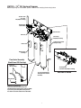
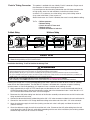
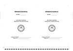
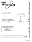
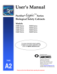
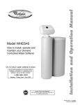
™
™
Owner's Manual
This Manual is for the Installation, Operation,
and Maintenance of the
WATER FACTORY SYSTEMS
™
CoolerMATE ™
Reverse Osmosis Systems
Model CMTRO-75
System tested and certified by NSF International against
NSF/ANSI Standard 42 and Standard 58 for the claims
specified on the Performance Data Sheet.
Installer: Please leave this manual with owner/operator.
End User: Please retain for operation and future maintenance instructions.
INSTR6064 1209
.
.
SAFETY INFORMATION
Read, understand, and follow all safety information contained in these instructions prior to installation and use of the CMTRO-75™
Reverse Osmosis (RO) Drinking Water System. Retain these instructions for future reference.
Intended use:
The CMTRO-75 Reverse Osmosis (RO) Drinking Water System is intended for use in filtering potable water in the home or office and has not
been evaluated for other uses. The system is typically installed in a cooler, under a sink or in a basement, and must be installed as specified in the installation instructions.
EXPLANATION OF SIGNAL WORD CONSEQUENCES
WARNING
CAUTION
CAUTION
Indicates a potentially hazardous situation, which, if not avoided, could result in death or serious injury
and/or property damage.
Indicates a potentially hazardous situation, which, if not avoided, may result in minor or moderate injury
and/or property damage.
Indicates a potentially hazardous situation, which, if not avoided, may result in property damage.
WARNING
To reduce the risk associated with choking:
• Do not allow children under 3 years of age to have access to small parts during the installation of this product.
To reduce the risk associated with ingestion of contaminants:
• Do not use with water that is microbiologically unsafe or of unknown quality without adequate disinfection before or after the system. Systems certified for cyst reduction may be used on disinfected water that may contain filterable cysts. EPA Establishment Number 070595-CT-001
To reduce the risk associated with hazardous voltage due to an installer drilling through existing electric wiring or water pipes in the area of
installation:
• Do not install near electric wiring or piping which may be in path of a drilling tool when selecting the position to mount the filter bracket.
To reduce the risk of physical injury:
• Shut off inlet water supply and depressurize system as shown in manual prior to cartridge removal.
• All hydropneumatic pressurized tanks must have an appropriate pressure relief valve installed.
To reduce the risk with back strain:
• Follow safe lifting procedures.
To reduce the risk associated with eye, skin and respiratory and digestive tract burns from Calcium Hypochlorite during installation:
• Calcium Hypochlorite (CAS 7778-54-3) granules are used for tank sanitization in this product.
• During installation, do not get in eyes or on skin or clothing. Do not ingest. Wear eye and face protection. Keep out of reach of children.
• To request an MSDS relating to this product, call 203-238-8965 or visit the web at http://solutions.3m.com/wps/portal/3m/en_us/MSDS (click
MSDS search). For emergencies, call 800-364-3577 or 651-737-6501 (24 hours).
To reduce the risk associated with ingestion of water contaminated with sanitizer:
• After installation, sanitizer MUST be flushed from the system before first use as directed within the installation instructions.
To reduce the risk of injury associated with household bleach:
• Read and follow manufacturers directions and cautions. Keep out of reach of children.
• DO NOT intermix with other chemicals.
CAUTION
To reduce the risk associated with property damage due to water leakage:
• Read and follow Use Instructions before installation and use of this system.
• Installation and Use MUST comply with all state and local plumbing codes.
• Protect from freezing, remove filter cartridge when temperatures are expected to drop below 40°F (4.4°C).
• Do not install on hot water supply lines. The maximum operating water temperature of this filter system is 100°F (37.8°C).
• Do not install if water pressure exceeds 100 psi (689 kPa). If your water pressure exceeds 80 psi (552 kPa), you must install a pressure limiting
valve. Contact a plumbing professional if you are uncertain how to check your water pressure.
• Do not install where water hammer conditions may occur. If water hammer conditions exist you must install a water hammer arrester. Contact
a plumbing professional if you are uncertain how to check for this condition.
• Do not use a torch or other high temperature sources near filter system, cartridges, plastic fittings or plastic plumbing.
• Where a backflow prevention device is installed on a water system, a device for controlling pressure due to themal expansion must be installed.
• All hydropneumatic pressurized tanks must have an appropriate pressure relief valve installed.
• On plastic fittings, never use pipe sealant or pipe dope. Use PTFE thread tape only. Pipe dope properties may deteriorate plastic.
• Take care when using pliers or pipe wrenches to tighten plastic fittings, as damage may occur if overtightening occurs.
• Do not install in direct sunlight or outdoors.
• Do not install near water pipes which will be in path of a drilling tool when selecting the position to mount the bracket.
• Mount filter in such a position as to prevent it from being struck by other items used in the area of installation.
• Ensure that the location and fasteners will support the weight of the system when installed and full of water.
• Do not install unit if collet is missing. Contact CUNO Tech Services (203-238-8847) if collets are missing from any fittings.
• Ensure all tubing and fittings are secure and free of leaks.
• The disposable filter cartridge MUST be replaced every 18 months, at the rated capacity or if a noticeable reduction in flow rate occurs.
IMPORTANT NOTES
• Failure to follow instructions will void warranty.
• Allow a minimum of 2” (5.1 cm) clear space under filter to facilitate cartridge change.
• Install with the inlet and outlet ports as labeled. Make sure not to reverse connections.
CMTRO - 75™ RO System Diagram
Before beginning the installation, spend a few minutes studying the drawing below.
To Cooler Tank
(3/8” Blue
Polyethylene Tubing)
Product Water
Outlet Fitting
Feedwater Inlet
Filter Icon
1/4" Orange
Polyethylene Tubing
Ty-Rap (Used to fasten
tubing to cooler)
Filter Icon
Bayonet Filter
Cartridge
Flow Control Assembly
(Back View of RO Cartridge)
Drain Line
(Green Tubing)
1
To StorageTank
(3/8 Yellow Polyethylene Tubing)
2
1/4” Green Polyethylene
Tubing with Flow Control
Assembly
Flow Control
RO Drain Line Construction:
1) Insert the thin flow control tubing with
attached bushing and stop into the 1/4 green tubing.
2) Insert the green tubing with bushing end into
the elbow located at the bottom of the RO module.
2
Back View of Bracket
I. Installation Requirements
CMTRO-75™ RO system, Model CMTRO-75 can be used with most coolers that include a storage tank. Check the
guidelines below to confirm that the CMTRO-75 system you have selected is the correct system for your water
conditions and water quality requirements.
Feedwater Criteria
Model
Total Dissolved
Solids
Hardness
pH
Temperature
Free Chlorine
Iron
Manganese
Hydrogen
Sulfide
Water
Pressure
Daily
Production*
CMTRO-75
< 2000 ppm
< 350 mg/l
4 - 11
40 - 100°F
(4.4 - 37.8°C)
< 1 mg/l
< 0.1 mg/l
< 0.05 mg/l
none
allowable
40 - 100 psi
(276 - 689 kPa)
23.59 gpd
(89.3 lpd)
per cartridge
* Systems are rated at 77°F (25°C), 60 psi (414 kPa), 500 ppm TDS. Actual production rate will depend on local
temperature, pressure, TDS level and membrane variation. Membrane output is affected by 1.5% for each degree
above or below 77°F (25°C). Lower temperature means less output, higher temperature means more output.
(However, systems must not be installed or operated on hot water lines. Observe temperature limits above).
Membrane output is also affected by water pressure.
II. Installation Procedure
Installing the filters.
Remove the CMTRO-75 filter cartridges from their sealed sanitary packages. Note that the “ears” on each cartridge fit
into slots on the receptacles. Moisten the o-rings with water and twist each cartridge slightly while inserting them into
the receptacle. The filters lock into place when pressed completely into the receptacle, and turned 1/4 turn to the right.
Be sure to match icons on the cartridges with the icons on the receptacles. This will ensure that you put the filters in
the correct position. Installation must comply with state and local plumbing codes.
Mounting the system.
CAUTION
To reduce the risk associated with property damage due to water leakage:
• Do not install near water pipes which will be in path of a drilling tool when selecting the position to mount the bracket.
• Mount filter in such a position as to prevent it from being struck by other items used in the area of installation.
• Ensure that the location and fasteners will support the weight of the system.
Mounting with bolts, screws, or studs (recommended).
1. There are two slots with keyholes to provide a variety of options for bolting or hanging the CMTRO-75 system on
the cooler. In some cases existing screws can be used. Further, there are keyholes for those who desire to install studs,
bolts, or screws at the required spacing to allow easy removal of the entire system.
Make tubing connections
With the CMTRO-75 system fastened to the cooler, the tubing connections can be made. All connections are made
with “Push-In” connectors. Refer to the diagram below and instructions on use of the “Push-In” plastic fittings. Use
care in routing the tubing to ensure that there are no sharp bends or kinks in the tubing.
1. Connect 3/8" yellow tubing from bracket (labeled tank) to storage tank.
2. Take 1/4" green tubing & RO Brine Flow control and insert the RO Brine Flow Control in one end of the 1/4"
green tubing (as shown in Figure). Insert the end of the tubing with the flow control into the drain connection.
3. Install other end of the long green tubing to drain. Be sure there is a proper air gap between the system & drain
lines and that local & State plumbing codes are followed.
4. Connect orange tubing from water supply to inlet port on bracket head.
5. Connect 3/8" blue tubing from outlet port on head assembly to cooler float/solenoid/reservoir fill connection.
We recommend the use of high quality tubing. The dimensional inconsistency of low quality tubing can cause leaks at
the“Push-In” fittings. We also recommend the installation of a ball valve at the point where you tap into the main water
line.
3
‘Push-In’ Tubing Connector
This product is outfitted with user friendly ‘Push-In’ connectors. Proper use of
the connectors is shown in the diagrams below.
It is most important that the tubing selected for use with these connectors be
of high quality, exact size and roundness, and with no surface nicks or
scratches. If it is necessary to cut the tubing, use a plastic tubing cutter or
sharp razor knife. Make a clean square cut.
Should a leak occur at a ‘Push-In’ connector, the cause is usually defective tubing.
To Fix: •
•
•
•
•
Relieve pressure
Release tubing
Cut off at least 1/4” from end
Reattach tubing
Confirm connection is leak free
To Attach Tubing
1
Tube
O-Ring
To Release Tubing
2
1
2
Grey Collet
Push tubing straight in as far as it will go.
Tubing is secured in.
Push in grey collet to release tubing.
Pull tubing straight out.
CAUTION
To reduce the risk associated with property damage due to water leakage:
• Ensure all tubing and fittings are secure and free of leaks.
Installation Sanitizing - Prefill & Sanitize the Storage Tank
WARNING
To reduce the risk associated with eye, skin and respiratory and digestive tract burns from Calcium Hypochlorite during installation:
• Calcium Hypochlorite (CAS 7778-54-3) granules are used for tank sanitization in this product.
• During installation, do not get in eyes or on skin or clothing. Do not ingest. Wear eye and face protection. Keep out of reach of children.
• To request an MSDS relating to this product, call 203-238-8965 or visit the web at http://solutions.3m.com/wps/portal/3m/en_us/MSDS (click
MSDS search). For emergencies, call 800-364-3577 or 651-737-6501 (24 hours).
To reduce the risk associated with ingestion of water contaminated with Calcium Hypochlorite sanitizer:
• After installation, sanitizer MUST be flushed from the system before first use as directed within the installation instructions.
Prefilling the storage tank is always recommended so that there is pressure to check for leaks as well as sufficient
water to flush the carbon postfilter. The CMTRO-75™ System is furnished with a container of special sanitizing
granules known as Calcium Hypochlorite. It is important to use a sanitizer when prefilling the tank.
1. Apply approximately 3 wraps of PTFE thread tape onto threaded tank stem. Locate the enclosed container of
sanitizing granules, open it and pour the contents into the end of the threaded tank stem. Install the 3/8" x 1/4"
tank valve onto the threaded tank stem. Do not overtighten.
2. Disconnect the 3/8” yellow tubing from the back of the filtration assembly and connect one end of it into the tube
fitting located on the tank valve.
3. Connect the other end of the 3/8” yellow tubing to the 3/8” x 1/4” union connector included in the tank sanitization kit.
4. Connect the free end of the 1/4” orange feed water tubing to the other end of the 3/8” x 1/4” union connector.
5. Open the cold water supply shut off valve (making sure the tank valve is still open) and allow the tank to fill
(about 3 minutes).
6. Close the cold water supply shut off valve and the tank valve. Disconnect the 3/8” yellow tubing from the tank
valve elbow fitting and set the tank aside while proceeding with the rest of the installation (the sanitizing solution
should be kept in the tank for at least 15 minutes).
4
7. Reconnect the 3/8” yellow tubing to the back of the filtration assembly. Reconnect the 1/4” orange tubing to the
feed water fitting on the filtration assembly.
IMPORTANT NOTES
• If you encounter difficulty in removing the tubing from the tank, make sure the tank valve is closed and then cut the yellow tubing approximately 1” away from the tank valve fitting to relieve the pressure. Remove the 1” piece from the tank fitting.
• If an alternate storage tank is used, it should be sanitized with household bleach (5-1/4%). Use 3 ml. (1/2 teaspoon) of bleach for a 2.5
gallon tank.
• After the installation is complete, it is recommended that the 3/8” x 1/4” union connector be saved for future use in tank sanitization.
III. Flush Instructions
1. With the tank valve closed (the tank should still contain the sanitizing solution at this point) disconnect the 3/8"
blue product line tubing from the cooler and run to drain. Open the feed line water valve. Water should begin to
drip from the line within several minutes. Continue to flush the system for 1 hour. Water will steadily drip from the
line at this time. During this procedure, the tank is being intentionally bypassed in order to thoroughly sanitize the
tank and also flush the membrane. Open the feed line water valve.
2. After flushing for 1 hour, open the tank valve and allow the tank to completely empty. When the tank is empty, the
blue tubing will drip steadily.
3. Allow the system to operate in this condition for 24 hours.
4. Close the ball valve and reinspect the appliance for leaks. Allow the tank to fill completely (it will take
approximately 1-2 hours), then drain the tank again. The water should be discarded because it may contain
some preservative / sanitizing solution.
5. The cooler should be ready to use as soon as the tank refills. If any objectionable taste is noticed after the
second tankful is drained, instruct the customer to wait and drain the tank the following day.
IV. Operation and Maintenance Instructions
CAUTION
To reduce the risk associated with property damage due to water leakage:
• The disposable filter cartridge MUST be replaced every 18 months, at the rated capacity or if a noticeable reduction in flow rate occurs.
Replacing the Filter Cartridges
The life of the prefilter cartridge generally depends on the local water conditions (i.e., sediment, rust and/or
chlorine levels) while the life of the postfilter cartridge(s) is generally determined by the length of service. It is
recommended that the cartridges be replaced as noted below.
When to Replace the Sediment/Carbon Prefilter Cartridge
•
Every 18 months or based upon your dealer's recommendation and knowledge of the local water conditions.
•
A noticeable decrease in water production may be an indication that the prefilter requires more frequent changing.
•
Recommended maximum sediment/carbon prefilter service life is 18 months.
When to Replace the Carbon Postfilter Cartridge
•
If the filter is being used to control tastes and odors, replace it every 18 months.
5
How to Replace the Prefilter and Postfilter Cartridges
1. Close the feed water valve and tank valve, then partially drain the cooler reservoir. Wait five (5) minutes for the
assembly to completely depressurize.
2. Twist the filter cartridge 1/4 turn to the left so that the ears on the cartridge are able to disengage from the head.
Firmly pull the cartridge from the head. It may be necessary to twist the cartridge slightly from side to side to help
free it. (See Illustration A, below.)
3. Remove the new filter cartridge from its sanitary sealed wrapper. (Double check to see that it is the correct
replacement by comparing the icon labels.)
4. Using tap water, food grade silicone lubricant or glycerin, wet the o-ring seals to make cartridge insertion easier.
5. Line up the cartridge ears, insert the cartridge and push it into the head until it is fully seated. Twist the cartridge 1/4
turn to the right to lock it into place.
Illustration A
6. Open the feed water valve and carefully check for leaks.
7. Prefilters: Disconnect blue 3/8" tubing from cooler & run to drain line. Flush
at least 2 gallons of water through filter before use.
Postfilters: Run blue 3/8" tubing to drain line. Flush at least 2 gallons of
water through postfilter before use.
Replacing The RO Membrane Cartridge
The life of the RO membrane cartridge depends on the local water conditions
and proper maintenance, e.g., regular filter changes. Under typical
conditions, the RO membrane life ranges from 18-36 months. Unlike the filter
cartridges, the RO membrane cartridge life is not determined by the amount
of water used because of its self-cleaning feature.
3
2
How to Replace the RO Membrane Cartridge
1. Close the feed water valve. Partially drain the cooler reservoir. Wait five (5)
minutes for the assembly to completely depressurize.
1
2. Make sure that there is some slack in the green tubing connected to the
fitting at the bottom of the RO membrane cartridge. Twist the cartridge 1/4
turn to the left so that the tubing connection is accessible. (See illustration
on the right.)
ON
3. Remove the green tubing by depressing the small white collet and pulling
the tubing away from the fitting.
Note: It is advisable to check the end of the green tubing for nicks or
scratches. If any are observed, cut off 1/4" from the end of the tubing with a
sharp razor knife.
4. Firmly pull the cartridge away from the head. (It may be necessary to twist
the cartridge slightly from side to side.)
5. Remove the new RO membrane cartridge from its sanitary sealed wrapper.
(Double check to see that it is the correct replacement by comparing the
icon labels.) Rinse it with tap water and dry it off.
6. Remove the white plug from the fitting at the bottom of the cartridge by
pushing in the small white collet and pulling out the plug.
Remove the green tubing
from the fitting before
completely removing the
RO membrane cartridge.
1
Prefilter Sediment/Carbon
2
Membrane
3
Postfilter/Carbon
OFF
7. Remove the red plastic cap from the top of the cartridge.
8. Using tap water, food grade silicone lubricant or glycerin, wet the O-ring
seals to make cartridge insertion easier.
9. Reconnect the green reject tubing by inserting it into the fitting at the bottom of the new RO membrane cartridge as
far as it will go. Ensure that the RO Brine Flow Control is correctly installed in the end of the tubing before
inserting the tube. Line up the cartridge ears, insert the cartridge and push it into the head until it is fully seated.
Twist the cartridge 1/4 turn to the right to lock it into place.
10. Open the feedwater valve and carefully check for leaks. Carefully inspect the fitting at the bottom of the new RO
membrane cartridge.
11. Flush RO product water to drain for 24 hours.
6
a 3M company
CUNO, CMTRO-75 and Water Factory Systems are
trademarks of 3M Company used under license.
NSF is a trademark of NSF International.
© 2009 3M Company. All rights reserved.
CUNO Incorporated
400 Research Parkway
Meriden, CT 06450 USA
Toll Free 1-800-733-1199
Worldwide 1-203-237-5541
Fax 1-203-238-8701
www.waterfactorysystems.com • www.cuno.com