1
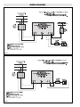
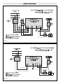
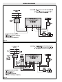
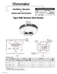
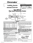
Installation, Operation
4
and
UB
(Supersedes PF424-3)
RENEWAL PARTS IDENTIFICATION
PF424-4
161-027049-001
JULY, 2002
Type UB-3502A, UB-4002A, UB-4502A, UB-5002A
Forced-Air Heater
Figure 1
(Wall Mounted)
Figure 2
(Ceiling Mounted)
Specifications – Table A
Model
Volts and Phase
kW
Horizontal
Air
Discharge
Wt.
(Lbs.)
UB-3502A
240V, 550V, 575V, 600V (3ø)
480V (1ø or 3ø)
35
54’
210
UB-4002A
480V (1ø or 3ø)
550V, 575V, 600V (3ø)
40
54’
210
UB-4502A
480V (1ø or 3ø)
550V, 575V, 600V (3ø)
45
54’
210
UB-5002A
480V, 550V, 575V, 600V (3ø)
50
54’
210
IMPORTANT
WARNING: Hazard of Electric Shock. Disconnect
all power before installing heater.
WARNING: This heater is not intended for use in
hazardous atmospheres where flammable vapors,
gases, liquids or other combustible atmospheres
are present as defined in the National Electrical
Code. Failure to comply can result in explosion or
fire. For these applications see PDS CXH-EP
(PF305).
© 2010 Chromalox, Inc.
WARNING: Users should install adequate back-up
controls and safety devices with their electric
heating equipment. Where the consequences of
failure may be severe, back-up controls are essential. Although the safety of installation is the
responsibility of the user, Chromalox will be glad to
make equipment recommendations.
IMPORTANT
The wall or ceiling mounting structure and the anchoring provision
must be of sufficient strength to support the combined weight of
the heater and mounting bracket. (Refer to Table A for weights of
heater and bracket).
Do not mount mercury type thermostat directly on unit. Vibration
could cause heater to malfunction.
The heater must be mounted at least 7’ above the floor to prevent
accidental contact with the heating elements or fan blade which
could cause injury.
Fan blade rotation must be checked. If airflow is not moving out
through the louvers, interchange any two of the three customer
power leads on three-phase units only.
Keep at least 5’ clearance in front of the heater. Refer to Figures 1
and 2 for side, top, and back clearance requirements.
MOUNTING
offered with these heaters. Minimum spacing to ceiling is
14-1/4”.
C. In either case the minimum mounting height is 7 feet from
floor to bottom of heater. (See Figures 1 and 2.)
2. Spacing to adjacent walls
A. Rear of case to back wall 11” minimum.
B. Side of case to side wall 12” minimum.
3. If two or more units are operated in the same enclosed space,
their discharges should be directed to aid in development of
mass air movement for uniform heat dispersal.
4. Controlling thermostats to individual heaters should be mounted at shoulder height on inside walls or columns.
WARNING: Hazard of Electric Shock. Disconnect all
power before installing heater.
WARNING: These heaters are designed for wall or ceiling mounting only. Other modes of mounting voids factory warranty.
1. Height above floor
A. In areas where ceiling height is more than 12 feet, recommended mounting height is approximately 10 feet to underside of heater.
B. For ceiling heights of 12 feet or less, maximum mounting
height is determined by use of ceiling mounting brackets
WIRING
2. If an external transformer is used to step down the voltage for
operating the fan motor, use appropriate wiring diagram (Figures
7 thru 14).
3. Heaters are not provided with a control switch and should be
controlled by externally mounted disconnect switches and/or
separately mounted thermostat and control switch as recommended in appropriate wiring diagrams (Figures 3 thru 14).
Key to proper wiring diagram is the part number (P/N) of internal wiring diagram located on inside of the hinged cover of the
terminal box.
4. Protection against overheating is provided by an internal automatic thermal cutout which opens the electric circuit if the normal air-flow is restricted or stopped. Cutout automatically
energizes heater on removal of the obstruction.
Note: All wiring should be done in accordance with local codes
and the National Electrical Code by a qualified person.
WARNING: Hazard of Electric Shock. Any installation involving electric heaters must be effectively
grounded in accordance with the National
Electrical Code to eliminate shock hazard.
1. Connect heater according to the voltage and frequency specified on the nameplate and using the appropriate wiring diagram
(Figures 3 thru 14).
Note: Be sure to check the voltage rating of the fan motor since
it is not necessarily the same as the heater circuit.
2
WIRING DIAGRAMS
Figure 3
Figure 4
3
WIRING DIAGRAMS
Figure 5
Figure 6
4
WIRING DIAGRAMS
Figure 7
Figure 8
5
WIRING DIAGRAMS
Figure 9
Figure 10
6
WIRING DIAGRAMS
Figure 11
Figure 12
7
WIRING DIAGRAMS
Figure 13
Figure 14
8
OPERATION
2. Do not operate heater in corrosive atmosphere conditions to
avoid destructive damage to heater.
3. Avoid operating heater in dusty environment which can foul
heater fins to dissipate heat or impair motor ventilation leading
to excessive operating temperatures.
4. Do not operate heater in ambient temperatures exceeding 90OF.
1. DANGER: Hazard of Fire.
A. Do not restrict air flow through heater by placing fabric or
other obstructions in front of or behind the heater. Increased
discharge temperatures can discolor or ignite some heat
sensitive combustible materials.
B. Do not operate heater in areas where combustible lint, dust
or flammable vapors, gases or liquids are present.
MAINTENANCE
2. Vacuum heater before activating heater for next heating season
to remove accumulated dust or lint which otherwise may
smoke or incinerate on initial heat up.
WARNING: Turn off all power to service heater. Do
not attempt to service heater while unit is operating as there is hazard of electric shock, injury from
operating fan, and burns from hot heating elements.
3. Periodically inspect all electrical connections and terminals to
avoid electrical wiring difficulties. Inspect all wiring for frayed
or worn insulation.
1. Fan motors in these heaters are provided with sealed ball bearings, factory lubricated, requiring no further lubrication under
normal service conditions.
9
RENEWAL PARTS IDENTIFICATION
1
HEATING ELEMENTS
1
1
Model
UB-3502A
UB-4002A
Voltage
Phase
Heating Element
240
3
118-117481-001 (6)
480
1 or 3
118-117481-002 (6)
550
3
118-117481-003 (6)
575
3
600
Model
Voltage
Phase
Heating Element
480
1 or 3
118-117481-010 (6)
550
3
118-117481-011 (6)
575
3
118-117481-012 (6)
118-117481-004 (6)
600
3
118-117481-013 (6)
3
118-117481-005 (6)
480
3
118-117481-014 (6)
480
1 or 3
118-117481-006 (6)
550
3
118-117481-015 (6)
550
3
118-117481-007 (6)
575
3
118-117481-016 (6)
575
3
118-117481-008 (6)
600
3
118-117481-017(6)
600
3
118-117481-009 (6)
UB-4502A
UB-5002A
10
RENEWAL PARTS IDENTIFICATION
2
MOTORS AND CAPACITORS
3
2 Motors
Part No.
3 Capacitors
Specifications
Manufacturer’s
Cat. No.
Volts Amps Phase Cycles RPM HP
Manufacturer’s Specifications
Cat. No.
Type Vac Cap.
Part No.
193-025776-001
HF2K007N
115
5.4
1
60
1625 1/3
040-025779-001
1270
Oil
370 5 MFD
193-025776-002
HF2K006N
230
2.54
1
60
1625 1/3
040-025779-002
1271
Oil
370 6 MFD
193-302120-011
P55YYBYV-887 460
0.9
3
60
1725 1/3
—
—
—
—
4
5
TRANSFORMERS
Voltages
Size
4 Large
Part Number
V.A. Rating
315-052169-011
Primary
970
315-052169-012
5 Small
315-304252-001
40
315-304252-003
6
Part Number
Fuses — 600 Volt
Manufacturer’s
Amps
Cat. No.
128-026510-003
30
JKS 30
128-026510-001
35
JKS 35
128-026510-004
40
JKS 40
128-026510-006
50
JKS 50
128-026510-007
60
JKS 60
128-027590-001
1
KTK-R-1
128-027590-008
8
KTK-R-8
128-027590-010
15
KTK-R-15
Secondary
220, 230, 240, 440, 460, 480
110, 115, 120
550, 575, 600
110, 115, 120
240 & 480
120
575
120
FUSES
Fuseholders
Use
Part Number
Power
129-025643-002
600 Volt, 30 Amp, 3 Pole
Power
129-025643-001
600 Volt, 60 Amp, 3 Pole
129-048473-001
2, 3, 4, 5 poles contact section
129-048475-001
End barrier section for use
with 129-048473-001
Control/
Motor
Description
PARTS COMMON TO ALL HEATERS
7
Fan . . . . . . . . . . . . . . . . . . . . . . . . . . . . . . . 112-027568-001
8
Fan Delay . . . . . . . . . . . . . . . . . . . . . . . . . . 300-048038-001
9
Cutout . . . . . . . . . . . . . . . . . . . . . . . . . . . . 300-049602-008
10
Manual Reset Cutout (Optional) . . . . . . . . . 300-117647-006
11
Grille . . . . . . . . . . . . . . . . . . . . . . . . . . . . . . 134-119147-004
12
Louver Assembly . . . . . . . . . . . . . . . . . . . . 182-047073-009
13
Mounting Bracket - (Right Hand) . . . . . . . . 027-025836-001
(Left Hand) . . . . . . . . . 027-025836-002
14
Thermostat (Optional) . . . . . . . . . . . . . . . . 300-026604-001
15
Contactor . . . . . . . . . . . . . . . . . . . . . . . . . . 072-304551-008
16
Auxiliary Contact . . . . . . . . . . . . . . . . . . . . 072-304551-101
11
—
Limited Warranty:
Please refer to the Chromalox limited warranty applicable to this product at
http://www.chromalox.com/customer-service/policies/termsofsale.aspx.
2150 N. RULON WHITE BLVD., OGDEN, UT 84404
Phone: 1-800-368-2493
www.chromalox.com